
Practical Action, The Schumacher Centre for Technology and Development, Bourton on Dunsmore, Rugby,
Warwickshire, CV23 9QZ, UK
T +44 (0)1926 634400 | F +44 (0)1926 634401 | E infoserv@practicalaction.org.uk | W
www.practicalaction.org
______________________________________________________________________________________________
Practical Action is a registered charity and company limited by guarantee.
Company Reg. No. 871954, England | Reg. Charity No.247257 | VAT No. 880 9924 76 |
Patron HRH The Prince of Wales, KG, KT, GCB
HYDRAULIC
RAM PUMPS
Introduction
The hydraulic ram pump, or hydram, concept was first developed by the Mongolfier brothers in
France in 1796 (they are better remembered for their pioneering work with hot-air balloons).
Essentially, a hydram is an automatic pumping device which utilises a small fall of water to lift
a fraction of the supply flow to a much greater height; ie it uses a larger flow of water falling
through a small head to lift a small flow of water through a higher head. The main virtue of
the hydram is that its only moving parts are two valves, and it is therefore mechanically very
simple. This gives it very high reliability, minimal maintenance requirements and a long
operation life.
How a hydram works
Its mode of operation depends on the use of the
phenomenon called water hammer and the overall
efficiency can be quite good under favourable
circumstances. More than 50% of the energy of the
driving flow can be transferred to the delivery flow.
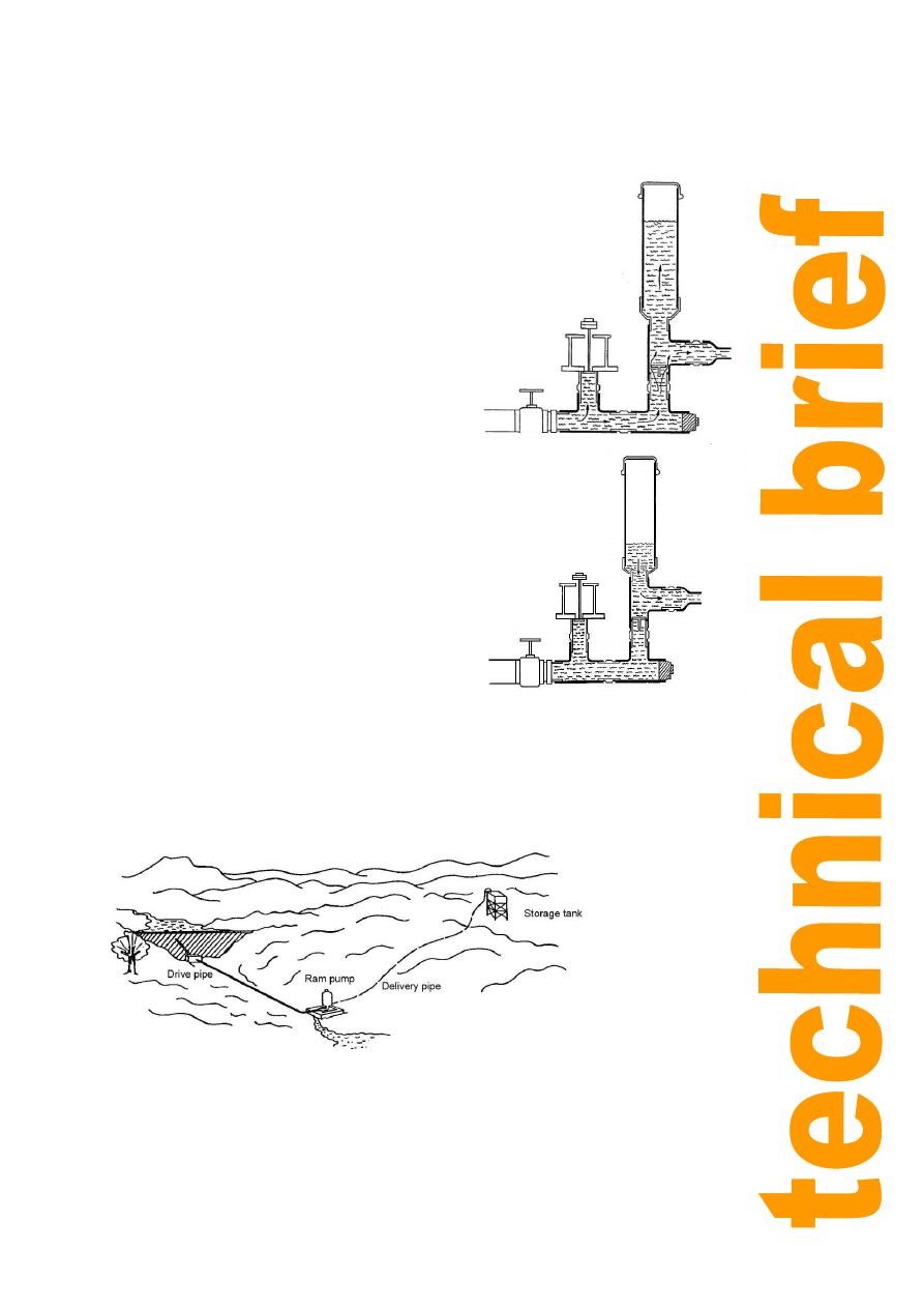
Figure 1 illustrates the principle; initially the
impulse valve (or waste valve since it is the non-
pumped water exit) will be open under gravity (or in
some designs it is held open by a light spring) and
water will therefore flow down the drive pipe (through
a strainer) from the water source. As the flow
accelerates, the hydraulic pressure under the
impulse valve and the static pressure in the body of
the hydram will increase until the resulting forces
overcome the weight of the impulse valve and start to
close it. As soon as the valve aperture decreases,
the water pressure in the hydram body builds up
rapidly and slams the impulse valve shut. The
moving column of water in the drive pipe is no
longer able to exit via the impulse valve so its
velocity must suddenly decrease; this continues to
cause a considerable rise of pressure which forces
open the delivery valve to the air-chamber.
Once the pressure exceeds the static delivery head,
water will be forced up the delivery pipe. Air
trapped in the air chamber is simultaneously
compressed to a pressure exceeding the delivery
pressure. Eventually the column of water in the
drive pipe comes to a halt and the static pressure
in the casing then falls to near the supply head
pressure. The delivery valve will then close, when
the pressure in the air chamber exceeds that in
the casing.
Stage 1: Water
flows through the
impulse valve.
Stage 2: Water
pressure increases
opening the
delivery valve
Figure 1: The hydraulic ram pump
Hydraulic ram pumps
Practical Action
2
Water will continue to be delivered after the delivery
valve has closed until the compressed air in the air
chamber has expanded to a pressure equal to the
delivery head. A check valve is included in the delivery
pipe to prevent return flow. When the delivery valve
closes, the reduced pressure in the hydram body will
allow the impulse valve to drop under its own weight,
thereby letting the cycle start all over again. Most
hydrams operate at 30-100 cycles a minute.
The air chamber is a vital component, as apart from
improving the efficiency of the process by allowing
delivery to continue after the delivery valve has closed, it
is also essential to cushion the shocks that would
otherwise occur due to the incompressible nature
of water. If the air chamber fills with water
completely, not only does performance suffer, but
the hydram body, the drive pipe or the air
chamber itself can be fractured by the resulting
water hammer. Since water can dissolve air,
especially under pressure, there is a tendency for
the air in the chamber to be depleted by being
carried away with the delivery flow. Different
hydram designs overcome this problem in
different ways. The simplest solution requires
the user to stop the hydram occasionally and
drain the air chamber by opening two taps, one to
admit air and the other to release water. Another
method on more sophisticated hydrams is to
include a so-called snifting valve which
automatically allows air to be drawn into the base
of the air chamber when the water pressure
momentarily drops below atmospheric pressure.
It is important with such units to make an
occasional check to see that the snifting valve has not become clogged with dirt and is working
properly.
This cycling of the hydram is timed by the characteristic of the waste valve. Normally it can be
Figure 2: The hydraulic ram pump system
Stage 3: air
chamber fills with
water compressing
the air
Stage 4: the
compressed air
forces the water
through the
delivery pipe
Figure 1: The hydraulic ram pump

Hydraulic ram pumps
Practical Action
3
weighted or pre-tensioned by an adjustable spring, and an adjustable screwed stop is generally
provided which will allow the maximum opening to be varied. The efficiency, which dictates
how much water will be delivered from a given drive flow, is critically influenced by the valve
setting.
This is because if the waste valve stays open too long, a smaller proportion of the throughput
water is pumped, so the efficiency is reduced, but if it closes too readily, then the pressure
will not build up for long enough in the hydram body, so again less water will be delivered.
There is often an adjustable bolt which limits the opening of the valve to a predetermined
amount which allows the device to be turned to optimise its performance. A skilled installer
should be able to adjust the waste valve on site to obtain optimum performance. Therefore, it
can be seen that the output of a hydram will be constant and is non-adjustable. A storage
tank is usually included at the top of the delivery pipe to allow water to be drawn in variable
amounts as needed.
Installation requirements
Figure 2 illustrates a typical hydram installation, pumping water to a small storage tank on a
plateau. It can be seen that the supply head is created in this case by creating a weir. In some
cases a small stream is diverted to provide the water supply. If the storage tank is for drinking
water, the volume of the tank can be half the volume of water delivered by the ram pump in
one day as the water is removed form the tank in the day time by people. Oversized tanks can
add unnecessary cost to the installation.
Where greater capacity is needed, it is common practice to install several hydrams in parallel.
This allows a choice of how many to operate at any one time so it can cater for variable supply
flows or variable demand. The size and length of the drive pipe must be in proportion to the
working head from which the ram operates. Also, the drive pipe carries severe internal shock
loads due to water hammer, and therefore normally should be constructed from good quality
steel water pipe. Normally the length of the drive pipe should be around three to seven times
the supply head. Ideally the drive pipe should have a length of at least 100 times its own
diameter. The drive pipe must generally be straight; any bends will not only cause losses of
efficiency, but will result in strong fluctuating sideways forces on the pipe which can cause it
to break loose.
The hydram body requires to be firmly bolted to a concrete foundation, as the beats of its
action apply a significant shock load. Some ram pumps should be located so that the waste
valve is located above flood water level, as the device will cease to function if the waste valve
becomes submerged. However, with the AID Foundation design of flap type waste valve the
vale should be submerged to ensure that during the recoil air will not enter through the waste
valve. Air already enters through the snifter. In this way the impact of the waste valve hitting
the waste valve stopper is also cushioned, so less wear and tear and less sound.
The delivery pipe can be made from any material capable of carrying the pressure of water
leading to the delivery tank. In all except very high head applications, plastic pipe can be
considered; with high heads, the lower end of the delivery line might be better as steel pipe.
The diameter of the delivery line needs to allow for avoiding excessive pipe friction in relation
to the flow rates envisaged and the distance the water is to be conveyed. It is recommended
that a hand-valve or check-valve (non-return valve) should be fitted in the delivery line near
the outlet from the hydram, so that the delivery line does not have to be drained if the hydram
is stopped for adjustment or any other reason. This will also minimise any back flow past the
delivery valve in the air chamber and improve efficiency.
However, if the pump is known to be
reliable the working performance can be improved by removing the gate valve and non return
valves in the delivery line. The diameters of the valves are much smaller than the pipe lines
and create additional friction.
Hydraulic ram pumps
Practical Action
4
Choice of hydram design
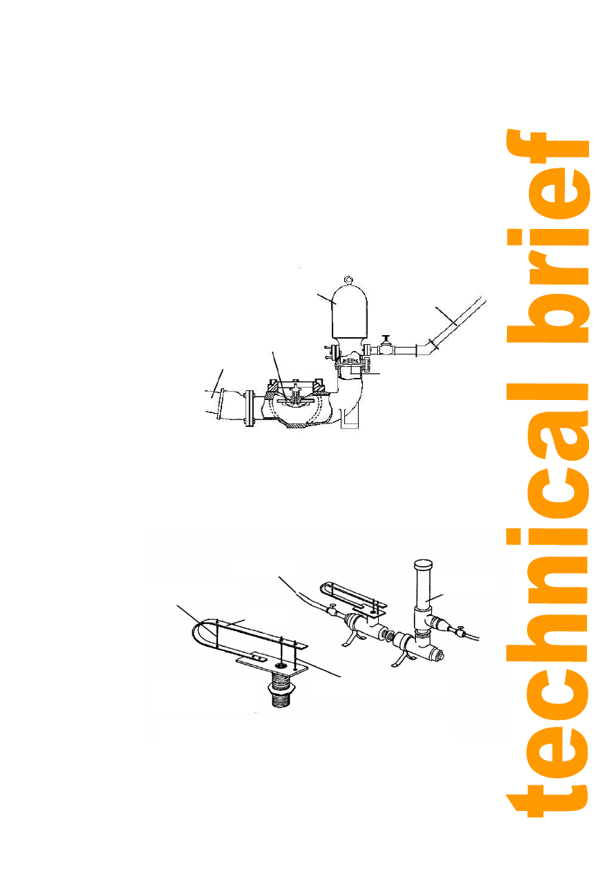
Traditional hydram designs, such as in Figure 3, developed a century ago in Europe, are
extremely robust. They tend to be made from heavy castings and have been known to function
reliably for 50 years or more. However, although a number of such designs are still
manufactured in Europe and the USA in small numbers, they are relatively expensive,
although generally speaking the drive-pipe, delivery pipe and civil workings will be significantly
more expensive than even the heaviest types of hydram.
Lighter designs, fabricated using a welded sheet steel construction, were developed first in
Japan and are now in production in other parts of South East Asia including Taiwan and
Thailand. These are cheaper, but only likely to last a decade or so as they are made from
thinner material which will
eventually corrode.
Nevertheless they offer good
value for money and are likely
to perform reliably.
Hydrams are mostly intended
for water supply duties, in hilly
or mountainous areas,
requiring small flow rates
delivered to high heads. They
are less commonly used for
irrigation purposes, where the
higher flow rates required will
usually demand the use of
larger sizes of hydram having
6-inch or 4-inch drive pipes.
Manufacturers usually describe
the size of a hydram by the
supply and delivery pipe
diameters (generally given in
inches even in metric countries because of the common use of inch sizes for pipe diameters);
e.g. a 6 x 3 hydram has a 6-inch diameter drive pipe and a 3-inch diameter delivery pipe.
Some simple
designs that can be
improvised from
pipe fittings have
also been
developed by aid
agencies (Figure
4), and some
interesting versions
have also been
quite crudely
improvised using
scrap materials,
such as a unit
which is being
produced in some
numbers in
southern Laos from
materials salvaged
from bombed
bridges and using
Figure 4: A ram pump made from standard pipe fittings
Figure 3: Traditional hydram
design
Delivery
valve
Air
chamber
Delivery
pipe
Impulse
valve
Drive
pipe
Drive pipe
Air
chamber
Stroke adjustment bolt
Spring
Impulse valve
assembly
Spring tension bolt

Hydraulic ram pumps
Practical Action
5
old propane cylinders for the air chamber. Needless to say, such devices are very low in cost
but the pipes in the end cost considerably more than the hydram. They are not always as
reliable as traditional designs, but are usually acceptably reliable with failures separated by
many months rather than days, and are easy to repair when they fail.
Performance characteristics
Table 1 indicates estimated performance for typical 4-inch x 2-inch and 6-inch x 3-inch
commercial hydrams.
Hydram size in
inches
4" X 2"
6" X 3"
Head Ratio
5 10
15
20
5 10 15 20
Driven flow
(litres/sec)
8.96
9.7
10 9.02
20.2 17.2 17.1
19.3
Delivery (m³/day)
94
51
35
23
216 101 69 50
Table 1: Estimated performance of hydrams
Costs
The costs of commercial hydrams are typically in the range from about £1500 for small 2-inch
drive pipe sizes up to as much as £5000 for 4-inch or 6-inch sizes. The cost of the drive pipe
can also be quite high for the larger sizes. Therefore hydrams are best suited to relatively low
flow rates and high head applications. Of course there are no fuel costs and negligible
maintenance costs associated with hydrams.
Further information
References
Hydraulic Ram Pumps: A Guide to Ram Pumps Water Supply Systems
Jeffery, T D,
Thomas T H, Smith A V, Glover, P B, Fountain P D. Practical Action Publications, 1992
A Manual on the Hydraulic Ram for Pumping Water
Publishing, 1975.
Renewable Energy Sources for Rural Water Supply in Developing Countries
Hofkes and
Visscher - International Reference Centre for Community Water Supply and Sanitation,
The Hague, The Netherlands - 1986.
Home Made Hydraulic Ram Pumps
Clemson University
http://www.clemson.edu/irrig/Equip/ram.htm
Suppliers
Note: This is a selective list of supplies and does not imply endorsement by Practical Action.
Green and Carter Rams
Vulcan Works
Ashbrittle
Wellington
Somerset
TA21 0LQ.
United Kingdom
Tel: +44 (0)1823 672365
E-mail:
John Blake, a division of Allspeeds Ltd.
Royal Works
Atlas Street
Clayton Le Moors
Lancashire, BB5 5LP
United Kingdom
Tel: +44 (0)1254 615100
Fax: +44 (0)1254 615199
E-mail:

Hydraulic ram pumps
Practical Action
6
Useful Addresses
AID Foundation (Alternative Indigenous Development Foundation, Inc.)
AIDFI Bldg., Murcia Road, Mansilingan,
6100 Bacolod City
Philippines
Tel: (+ 63) 034 - 4463629
Fax: (+ 63) 034 - 4462330
E-mail:
Website:
AID Foundation has worked on various technologies including ram pumps, handpumps,
footpumps, biogas, rice hull stoves, ferro-cement reservoir, biogas and essential oil distiller.
The rampump body is made from welded steel plates and the air chamber of galvanized iron
pipes. Most important parts like checkvalve plate, waste valve and waste valve stopper are
from stainless steel. The design uses flap valves rather piston type which improve reliability.
Water can be pumped to a height of 220 meters. AID Foundation wants to share the
technology with others internationally and is prepared to develop a technology transfer plan
with suitable groups and small enterprises.
http://www.youtube.com/watch?v=0ovPSSOs76U
YouTube video
http://www.youtube.com/watch?v=zIJoowE2tz0
Afghanistan.
Development Technology Unit (DTU)
School of Engineering
University of Warwick
Coventry CV4 7AL
United Kingdom
Tel: +44 (0)1203 522339
Fax: +44 (0)1203 418922
E-mail:
http://www.eng.warwick.ac.uk/DTU
http://www.eng.warwick.ac.uk/DTU/pubs/lift.html
Development Technology Unit who has carried out a lot of research into simplifying the
construction of hydraulic ram pumps. The DTU is a research unit within the School of
Engineering at the University of Warwick in the UK. The aim of the DTU is to research and
promote appropriate technologies for application in Developing Countries.
WOT - Werkgroep Ontwikkelingstechnieken - Working Group on Development Techniques
Vrijhof 205/206
P.O. Box 217
7500 AE Enschede
Netherlands
Tel: +31 53 489 3845
Fax: +31 53 489 2671
E-mail:
WOT is a non-profit organisation working in the field of small-scale sustainable energy, based
at the University of Twente, Netherlands. The WOT ram pump design is for very small-scale
applications and uses standard components. The design is available online
http://www.wot.utwente.nl/knowledgecenter/publications/breurram.html
Demotech
Biesenwal 3

Hydraulic ram pumps
Practical Action
7
6211 AD Maastricht
Netherlands
Tel: +31 (0)6 174 771 77
E-mail:
Website:
Experimental concrete ram pump design, still in the research stage.
YouTube video.
http://www.youtube.com/watch?v=sPylLw_R94k
http://www.youtube.com/watch?v=f4ngVxNF7Uw&feature=related
Practical Action
The Schumacher Centre for Technology and Development
Bourton-on-Dunsmore
Rugby, Warwickshire, CV23 9QZ
United Kingdom
Tel: +44 (0)1926 634400
Fax: +44 (0)1926 634401
E-mail:
inforserv@practicalaction.org.uk
http://practicalaction.org/practicalanswers/
Practical Action is a development charity with a difference. We know the simplest ideas can have the
most profound, life-changing effect on poor people across the world. For over 40 years, we have been
working closely with some of the world’s poorest people - using simple technology to fight poverty and
transform their lives for the better. We currently work in 15 countries in Africa, South Asia and Latin
America.
Wyszukiwarka
Podobne podstrony:
Hydraulic ram pumps
38 Zawory hydrauliczne
Właściwości hydrauliczne
hydraulika oprcowanie pytania 2013 (chyba)
AVB hydrauliczne naprążanie paska rozrządu
45 06 BW Hydraulika stosowana
Instrukcja 16 Rozpoznawanie elementow hydraul
Hydraulika02
INSTRUKCJA OBSŁUGI HYDRAULICZNEJ NADZIEWARKI DO KIEŁBAS(1), GOTOWANIE I ŻYWIENIE, GASTRONOMIA
Cwiczenie zabawowe, STUDIA, Polibuda - semestr II, Hydraulika i hydrologia, laborki z hydro
Lab. N1 (5 semestr), BUDOWNICTWO ZUT, SEMESTR V, Hydraulika i Hydrologia
linia cisnien, STUDIA, Polibuda - semestr II, Hydraulika i hydrologia, laborki z hydro, laborki
Jak mieć wolną pamięć RAM, A TO POTRZEBNE
OBLICZANIE HYDRAULICZNE PRZEWODÓW, Inżynieria Środowiska, Różne
straty lokalne, STUDIA BUDOWNICTWO WBLIW, hydraulika i hydrologia
więcej podobnych podstron