level of difficulty
beginner
intermediate
advanced
Celestial Navigation Fundamentals
Note: This is the first chapter of the manual of Navigator Light, a DOS program I developed in 1993 (yes,
my Navigator is older than Netscape's). The original Portuguese full text is available in this site.
This text is available in English, French and Portuguese
Angles, angles, angles...
Angles are the most common type of number used by the celestial navigator. The position of the celestial bodies
and points on the surface of the earth may be described by angles. The sextant is an instrument that measures
angles. Angles are usually measured in degrees, minutes and seconds. The complete circumference has 360
degrees (360°). One degree is equivalent to 60 minutes. The seconds of arc are not used in the celestial navigation,
since the angle measurement instrument - the sextant - is not precise enough to measure them. The smallest unit of
angle used by navigators is the tenth of minute. Recently, the popularization of GPS devices added the 1/100 of
minute.
The nautical mile (=1852 m) is a unit conveniently selected to simplify the conversions between angles and
distances. One nautical mile corresponds to an arc of one minute on the surface of earth. Angles and distances on
the surface of earth are, therefore, equivalent. One exception is the minute of longitude, equivalent to one mile only
near the Earth Equator. Another important equivalence is between time and degrees of longitude. Since the earth
goes one complete turn (360°) in 24 hours, each hour corresponds to 15° of longitude. Or 900 Nautical miles (NM).
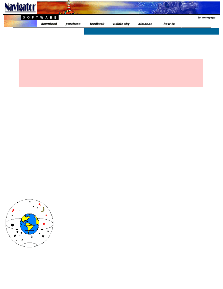
The Earth and the Celestial Sphere.
Fig. 1 - The Earth and the
Celestial Sphere
Imagine that the Earth is the center of the universe and that around the Earth there is a
larger sphere, centered in the same point, in which the stars are fixed, as if they were
painted in its internal surface. This other ball we call the
Celestial Sphere.
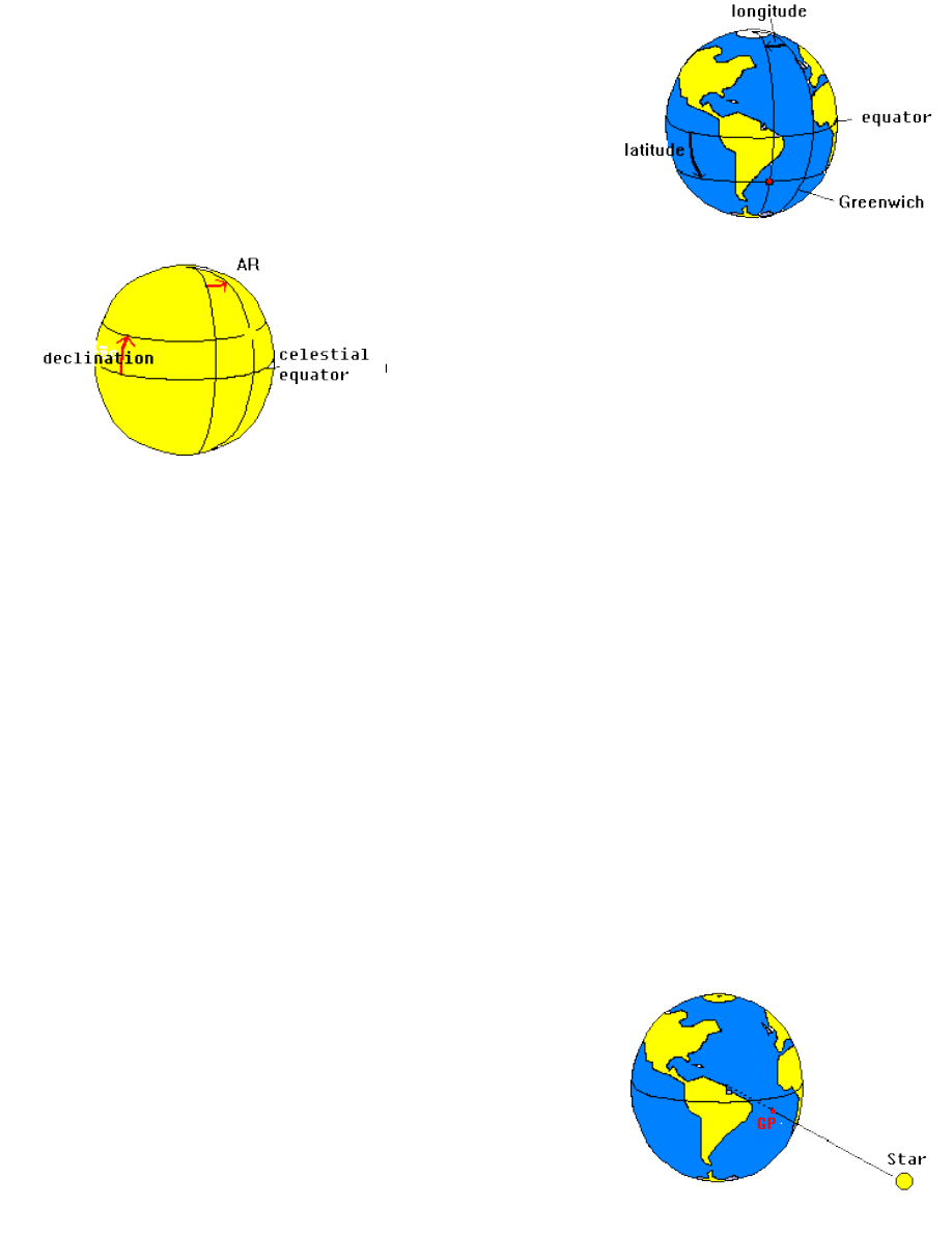
To specify a position on the surface of Earth we use a system of
coordinates that consists of two angles: latitude and longitude.
Latitude is
the angle measured from the Equator in direction North-South.
Longitude
is the angle in the Pole between the Meridian of Greenwich and that of the
considered position (fig. 2).
fig. 2 - Earth coordinate system
fig. 3- Celestial Coordinate System
A similar system is used for the Celestial Sphere. The angle
analogous to the latitude in the celestial sphere we call
declination. The declination is measured in the plane North-South,
from the Celestial Equator. The analog to the longitude is named
Right Ascension or RA. Like the longitude, the Right Ascension is
measured from an arbitrary Meridian: the Vernal Equinox Point (a.k.
a. first point of Aries).
Apparent movement of the stars
The stars have nearly fixed positions in the Celestial Sphere. The Sun, Moon and planets move around during the
year, but their movement is slow when compared to the apparent movement due to the rotation of the Earth. So let's
consider for now that the celestial objects ( stars, planets, Sun and Moon) are fixed in the Celestial Sphere.
Using the Earth-at-the-center-of-the-universe model, imagine that the Earth is stopped and the celestial sphere is
turning around it, completing a turn every 24 hours. You should not be confused by this idea: it's exactly what you
observe if you seat and watch the night sky long enough.
The Earth's and Celestial Sphere's axes of rotation are in the same line. Both equators are, therefore, in the same
plane (see fig. 1).
The stars, fixed to the celestial sphere, turn around the earth. The celestial sphere poles, being in the axis of
rotation, remain fixed in the sky. So, a star located near a celestial pole will appear to be stationary in the sky. That's
the case of
Polaris, a star that is near the North Celestial Pole (its declination is 89°05' N). It's always in the north
direction, a wonderful fact known by every navigator. Unfortunately there's no corresponding bright star near the
South Celestial Pole.
Finding the Earth position by observing the stars
Now consider a line connecting the center of a star and the center of the
Earth. The point where this line crosses the surface of the Earth we call
Geographical Position of this star (or GP). An observer positioned in the
GP of a star will see it directly in the vertical, above the head.
Since stars move with the celestial sphere, their GPs also move on the
surface of the Earth. And they are fast. The Sun's GP, for example, travels
a mile every four seconds. The GPs of other stars, closer to the celestial
poles, move more slowly. The GP of Polaris moves very slowly, since it's
very close to the North Pole.
Fig. 4- Geographical Position of a Star
Because both Earth and Celestial equators are in the same plane, the latitude of the GP is equal to the declination
of the star. The longitude of the GP is known as
Greenwich Hour Angle - or GHA - in a reference to the
correspondence between hours and longitude.
We can determine, using a Nautical Almanac, the GP of a star (it's GHA and declination) in any moment of time. But
we must know the exact time of the observation. As we have seen, 4 seconds may correspond to one mile in the GP
of a star. This shows the importance of having a watch with the correct time for the celestial navigation. The Beagle
- ship of Charles Darwin's travel in 1830 - carried 22 chronometers on board when she went around the globe in a
geographic survey.
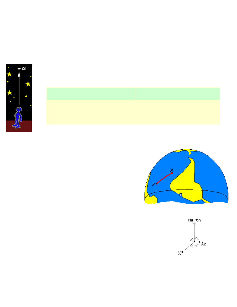
Zenith
Another important point is the
Zenith. The Zenith is the point in the celestial sphere located in the
vertical, over the head of the navigator. The line that connects the Zenith and the center of the Earth
crosses the surface in the position of the navigator, the one we want to find. So, we have the
following correspondence between points:
Surface of Earth
Celestial Sphere
Geographical Position of a star
Center of the star
Position of the navigator
Zenith
In the figure 5, the GP of the star is represented by X and the Zenith
by Z. The distance XZ, from the GP of the star to the point Z of the
navigator is called
Zenith Distance. This distance, as we have
seen, can be expressed in miles or degrees, since it's an arc on the
surface of the Earth.
fig. 5 - GP of a star and the Zenith
The angle that XZ makes with the True North (i.e. the "bearing" of the star)
is called
Azimuth ( Az ) (fig. 6).
fig. 6 - Azimuth of a star
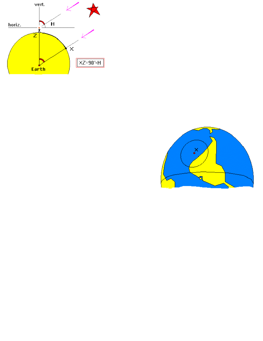
fig.7 - Altitude and Zenith distance of a star
The stars are at a great distance from the earth and so the light rays
coming from them that reach the Earth are parallel.
Therefore, as illustrated in the figure 7, we may say that the distance
XZ (as an angle) is equal to the angle that the navigator observes
between the star and the vertical. This is important.
The distance
XZ, measured as an angle, is equal to the angle that the
navigator observes between the star and the vertical.
However, it's difficult to determine the Zenith distance with precision, since it's difficult to find the vertical direction in
a rocking boat. It's a lot easier to measure the angle between the star and the horizon. This important angle for the
celestial navigator is called
altitude (H) of the star. The altitude of a star is taken with the sextant held in the vertical
plane, measuring the angle between the horizon and the star. In the fig. 7, we can see that the zenith distance
equals 90° less the altitude of the star.
We have seen how to determine the zenith distance of a star using
the sextant. The Zenith Distance and the GP of a star, however, are
not enough to determine our position. With this data we can only say
that our position is in a big circle, with the center in the GP of the
star and radius equal to the Zenith Distance. This is known as the
Circle of Position. Figure 8 shows a Circle of Position. Point X is
the GP of the star.
fig.8 - Circle of Position
Any observer located on this circle will see the star at the same altitude, but with different Azimuths. In the example
of the figure, suppose the navigator observes the star with an altitude of 65°. As we have seen, the Zenith Distance
is 90°-H, or 25°. To determine this distance in miles, we multiply by 60, since one degree is equal to 60 nautical
miles (NM). So, the Zenith Distance in the example - the radius of our circle - is 1500 NM.
If we just could determinate the exact direction where the GP of the star is - it's Azimuth - that would establish where
in the circle we are. How about using a compass? Unfortunately, the compass is not precise enough for celestial
navigation. One error of just 3°, common when reading a compass, corresponds to 78 miles of error in our example!
Not an acceptable error.
The way to find our position is to draw two or more circles - for two or more celestial bodies - and see where they
intercept each other. But drawing these big circles would require really big charts! We work around this problem by
making a guess at our
position. No matter how lost we are, we can always make a guess. Using this assumed
position we can calculate expected altitude for the star at a given time (using the Nautical Almanac).
This
Calculated Altitude can then be compared with the Observed Altitude (the actual altitude, measured with the
sextant). The difference is the error of our assumed position ( also known as
Delta ) in the direction of the star. The
Delta can be towards the star or away from it.
>> Click here for the next page
>> Homepage

level of difficulty
beginner
intermediate
advanced
Celestial Navigation Fundamentals - Continued
This text is available in English, French and Portuguese
<< click here to go to previous page
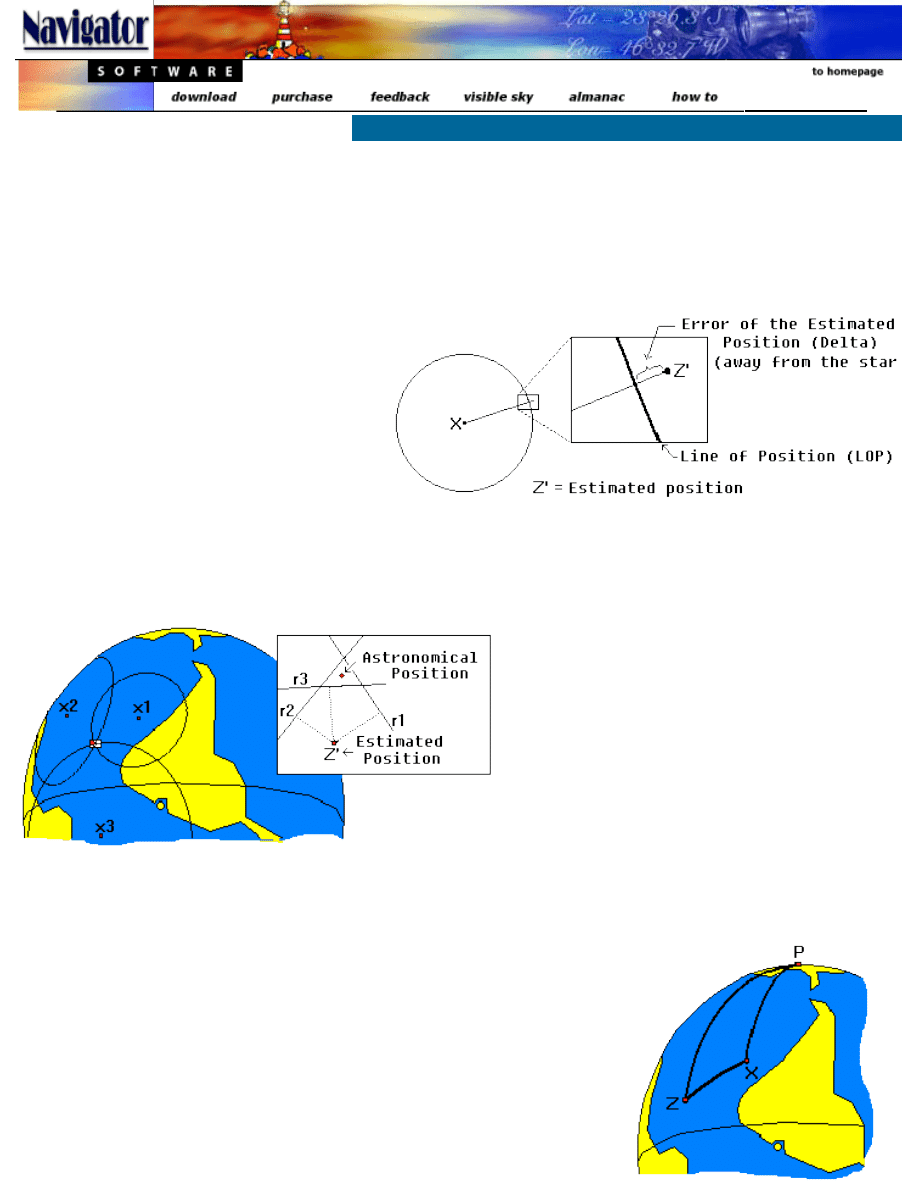
Because a Geographical Position of a star is
normally thousands of miles from our position,
the circle of position is very large and the small
piece that interests us - the one near our
position - may be considered a straight line,
orthogonal to the Azimuth of the star. This line
is called the
Line of Position or LOP (fig. 9).
fig. 9 - Line of Position
We managed, from the measured altitude of a star at a certain time and our assumed position, to draw a line of
position. We know that our actual position is somewhere along this line. To determine this point we can draw another
line, for another star. The point were they intercept each other is our position - or our
Astronomical Position.
fig. 10 - Triangle formed by the intersection of three lines of Altitude
Normally, the navigator should repeat this
procedure for yet another star, just to be sure.
Since measurements are affected by minor
imprecisions, the three lines will probably not
intercept in a single point, resulting in a small
triangle. Our position is probably in some point of
this triangle (fig. 10). The smaller the triangle, the
better. We usually assume that our Astronomical
Position is in the center of the triangle.
In figure 10 above, we can see how three circles of position determine 3 Lines of Position r1, r2 and r3.
In traditional celestial navigation the determination of a Line of Position
involves the computation of the GP of the star (GHA and declination) using
the Nautical Almanac and the solution of the
Position Triangle PXZ, formed
by the terrestrial pole (P), the GP of the star (X) and the assumed position of
the navigator (Z) (see fig.11).
This solution, using tables, yields the Calculated Altitude and the Azimuth of
the star. The difference, in minutes of degree, between the calculated altitude
and the altitude of the star measured with the sextant is the distance
between the line of position and our assumed position - the error
Delta of our
estimate. This can be away or towards the star.
fig. 11 - Triangle of Position PXZ
Using Navigator software, the GP of a star and the triangle of Position are solved by the computer using formulas. All
you will have to do is enter the sextant reading (date, time and altitude), name of the star and the assumed position
(latitude and Longitude).
Determination of the Astronomical Position
It's not necessary to draw the lines of position when using Navigator software. But let's see how this is done using
pencil and paper:
1. Plot your assumed position.
2. Using a parallel ruler, draw a line passing on the assumed position, in the direction of the Azimuth of the star.
3. Over this line, measure the error Delta of the estimate - in the direction of the star or contrary to it - according
to the sign of the Delta.
4. Draw the line of position, orthogonal to the Azimuth, at this point.
Detailed Nautical Charts are usually only available for places near the shore. When in high seas, we normally don't
have charts with the adequate scale to plot our position. Special plotting paper is used instead.
When navigating using Navigator software, the computer determines the altitude lines interceptions and calculates
the astronomical position. A simplified map is drawn, showing the parallels, meridians, lines of altitude and the
astronomical position.
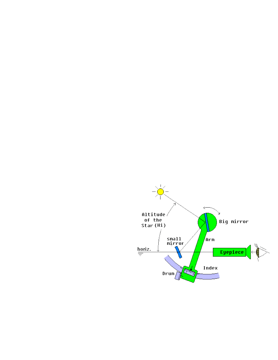
The sextant
The sextant is an instrument that measures angles. Fig
12 shows a schematic sextant. The
eyepiece is aligned
to the
small mirror, which is fixed in the frame of the
instrument. This mirror is half transparent. By the
transparent part, the navigator can see the horizon
directly. The small mirror also partially reflects the
image from the big mirror, where you see the star. The
big mirror is mobile and turns with the arm of the
sextant. Doing that, we change the angle between the
two mirrors. The altitude of the star is measured in the
scale. There is a drum to make the fine adjustments.
Whole degrees are read in the scale and the minutes in
the drum.
fig. 12 - The Sextant
sextant working model (requires Flash 5.0 plug-in)
The sextant has two sets of filters (or shades) to eliminate the excess of light, especially when observing the Sun.
The use of two or more filters in front of the big mirror is necessary when observing the Sun.
Serious eye injuries
will result from observing the Sun without filters, even for a brief period.
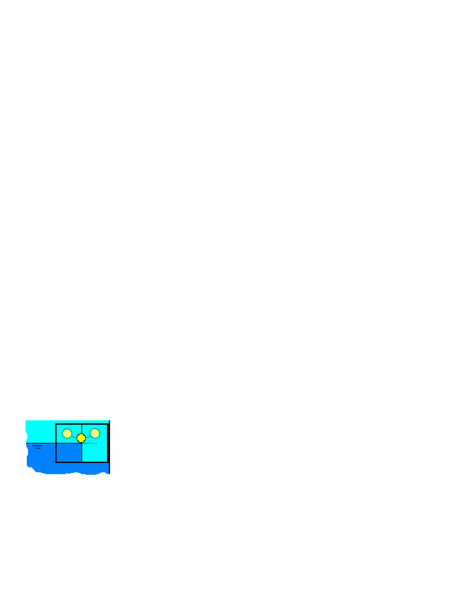
fig. 13 - Image of the Sun in the
sextant
When looking through the eyepiece and adjusting the sextant, you will see
something like figure 13, to the left. Sextant readings must be made with the sextant
in the vertical position.
Inclining (rocking about the axis of the eyepiece) the adjusted instrument slightly, the
image of the celestial body describes a small arc that touches the horizon in a point
near the center of the mirror. In this situation, the angle is ready to be read in the
instrument scale.
Altitude corrections
But before we can use this apparent reading in our calculations, some corrections must be made, in order to obtain
the true observed altitude. These corrections are: 1) the height of the eye, 2) semi diameter of the body (only for Sun
and Moon), 3) instrumental error, 4) atmospheric refraction and 5) parallax (only for the Moon).
Since most of these corrections depend only on the selected celestial object and altitude, they are performed
automatically by Navigator software. The only information you will have to provide to the program are the height of
the eye (a.k.a. Dip) and the instrumental error. The application of these corrections to the instrumental altitude
gives the corrected altitude, the one used in calculations.
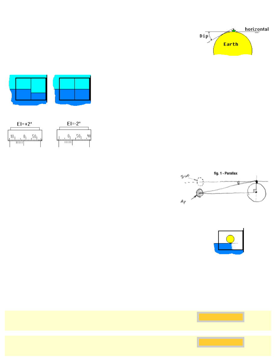
An observer located in a high place will see a star with an altitude bigger than other
at sea level, in the same location. This error is called height of the eye (Dip).
fig. 14 - Error due to the height of
the eye (Dip)
fig. 15 - eyepiece image of the sextant
index error
The sextant index error (IE) is due to a small misalignment of the scale of
the sextant (the "zero" of the instrument). To read the index error, adjust the
scale to 0°00.0' and point towards the horizon. In fig. 15 left we can see this
error. Turn the drum until the horizon forms a single line (fig. 15 right). Then
you can read the index error.
fig. 16 - Sign of the instrumental error
The index error can be positive or negative, as shown in fig. 16. The index
correction has opposite signal (i.e. must be subtracted from altitude if
positive and vice-versa)
Parallax error is illustrated in fig.17. Since the navigator is not in the
Earth's center, but in its surface, the apparent object position is below the
true geocentric position.
Parallax is only meaningful for the Moon. Other objects are so far, their
parallax is very small.
fig. 17 - Parallax in altitude error
Nautical Almanac data is tabulated for the centers of the celestial objects. For
the Sun and Moon, however, it's easier to measure the altitude of the lower
part of the body, as illustrated in fig. 18. This is known as the lower limb. Of
course a correction must be applied in order to obtain the altitude of the center
of the body. This correction is called semi diameter. Sometimes, the upper
limb is also used.
fig. 18 - Semi diameter correction
Now that you know how celestial navigation works, take a look in the
---xxx---
Bibliography
>> "Celestial Navigation for the Yachtsmen " by Mary Blewitt
ISBN 0070059284 - 112 pages
Good and small book, with easy methods. A classic.
>> "Ocean Yachtmaster" by Pat Langley-Price, Philip Ouvry
ISBN 0713645539- 215 pages
Heavier book, with complete theory and practice of celestial navigation, with examples.

>> "The American Practical Navigator " by Nathaniel Bowditch
ISBN 0781220211 - 1200 pages
A must in every advanced navigator library. The first edition of this book was published in 1802. It has been said to be one of
the few things a sailor absolutely needs before going to the sea, the other things being a "Bible and the mother's blessing".
Overtime, some of the original Bowditch's celestial navigation text was replaced by more modern subjects, like radar and radio
communications. Unfortunately, the Lunar calculation section is one thing that was removed, apparently in 1914. If you have a
copy of this text, I would like to read it <please!>.
Bowditch Online, where the full current edition text is available (PDF format).
For those who don't know Bowditch, I recommend the book "
Carry on, Mr.
Bowditch" by Jean Lee Latham, a somewhat romanced biography of this
great navigator.
Another interesting site is the
>> "Memento Vagnon de la Navegacion Astronomique" by François Meyrier
Good celestial navigation course in French, with step-by-step approach.
>> "Navegação astronômica" por Geraldo Luiz Miranda de Barros
Edições Marítimas - 250 páginas
Bom livro de navegação astronômica em Português.
Omar F. Reis - All rights reserved
Document Outline
- www.tecepe.com.br
Wyszukiwarka
Podobne podstrony:
Celestial Navigation
Celestial Navigation Basics(1)
Short Guide to Celestial Navigation 2001 Umland
(Ebooks) Seamanship The Elements Of Celestial Navigation
Basic Principles Of Celestial Navigation James Allen
Short Guide to Celestial Navigation 2003 Umland
A Short Guide to Celestial Navigation (2001)
TAB 1 Fundamentals Chapter 1 Introduction to Marine Navigation
p 43 ZASADY PROJEKTOWANIA I KSZTAŁTOWANIA FUNDAMENTÓW POD MASZYNY
Rodzaje fundamentów
Fundamentals
RF04 T07 Analiza fundamentalna
21 Fundamnety przyklady z praktyki
Fundamenty bezpośrednie
więcej podobnych podstron