
EMISSION
CONTROL
S Y S T E M
Return To Main Table of Contents
[MPI SYSTEM]
GENERAL . . . . . . . . . . . . . . . . . . . . . . . . . . . . . . . . . . . . . . . . . . . . . .
CRANKCASE EMISSION CONTROL SYSTEM . . . . . . . . . . 8
EVAPORATIVE EMISSION CONTROL SYSTEM . . . . . . . . 9
EXHAUST EMISSION CONTROL SYSTEM . . . . . . . . . . . . 13
[FBC SYSTEM]
GENERAL . . . . . . . . . . . . . . . . . . . . . . . . . . . . . . . . . . . . . . . . . . . . .
CRANKCASE EMISSION CONTROL SYSTEM . . . . . . . . . 2 5
GENERAL (MPI)
GENERAL
SPECIFICATIONS
Components
Function
Crankcase Emission Control System
Positive crankcase ventilation (PCV) valve
HC reduction
Evaporative Emission Control System
Canister
Purge control solenoid valve
Exhaust Emission Control System
MPI system (air-fuel mixture control device)
3-way catalytic converter
Exhaust gas recirculation system
EGR valve
Thermo valve
HC reduction
CO, HC, NOx reduction
CO, HC, NOx reduction
NOx reduction
Remarks
Variable flow rate type
ON/OFF solenoid valve
Oxygen sensor feedback type
Monolith type
Single type
Bimetal type
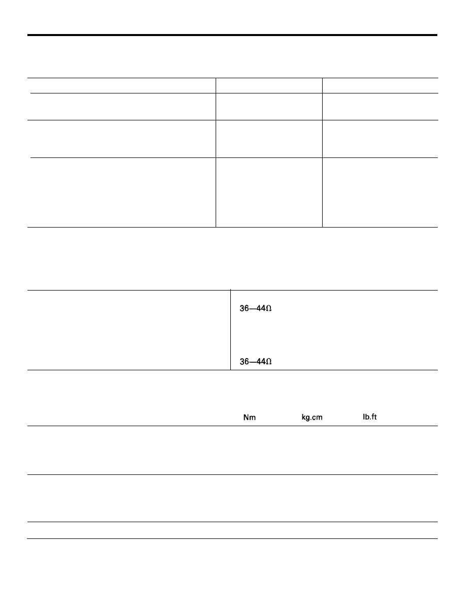
SERVICE STANDARD
Purge control solenoid valve
Coil resistance
Thermo valve temperature
Opening temperature
Closing temperature
EGR control solenoid valve
Coil resistance
TIGHTENING TORQUE
[at 20°C (68°F)]
MIN. 50°C (122°F)
6 1 - 6 9 ° C ( 1 4 2 - 1 5 6 ° F )
[at 20°C (68°F)]
Positive crankcase ventilation valve
87-12
8 0 - 1 2 0
5 . 8 - 8 . 7
EGR valve installation bolt
1 0 - 1 5
1 0 0 - 1 5 0
7 - 1 1
Thermo valve
2 0 - 3 9
2 0 0 - 4 0 0
1 4 - 2 9
EGR temperature sensor
1 0 - 1 2
1 0 0 - 1 2 0
7 . 3 - 8 . 6
SEALANT
Thermo valve thread portion
LOCTITE 962T or equivalent
2 9 - 2

GENERAL (MPI)
TROUBLESHOOTING
Symptom
Engine will not start or hard
to start
Rough idle or engine stalls
Engine hesitates or poor
acceleration
Excessive oil consumption
Poor fuel mileage
Probable cause
Vacuum hose disconnected or damaged
The EGR valve is not closed
Malfunction of the purge control
solenoid valve
The EGR valve is not closed
Vacuum hose disconnected or damaged
Malfunction of the PCV valve
Malfunction of the purge control system
Malfunction of the exhaust gas recircula-
tion system
Positive crankcase ventilation line
Check positive crankcase ventila-
clogged
tion system
Malfunction of the exhaust gas recircula-
tion system
Check system; if a problem exists,
check component parts
Remedy
Repair or replace
Repair or replace
Repair or replace
Repair or replace
Repair or replace
Replace
Check the system; if there is a pro-
blem, check its component parts
Check system; if a problem exists,
check component parts
2 9 - 3
GENERAL (MPI)
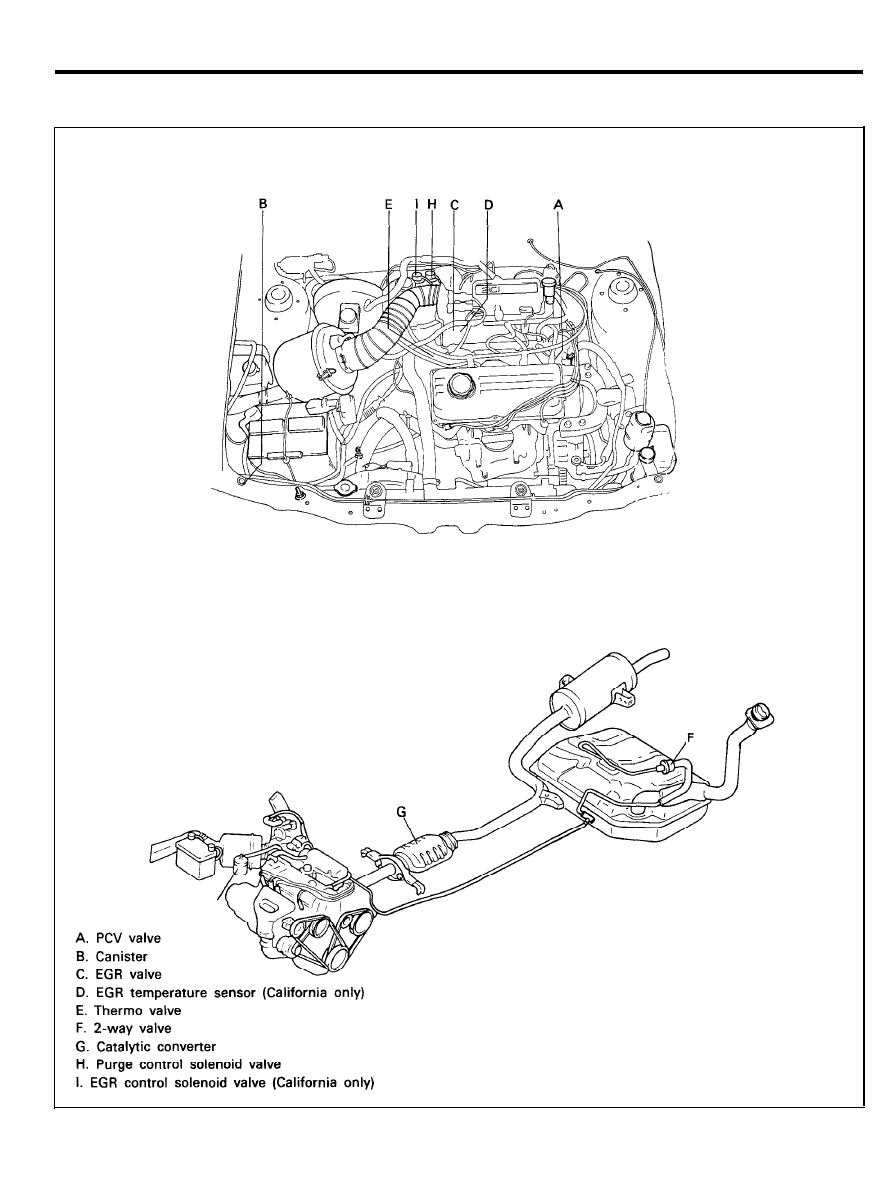
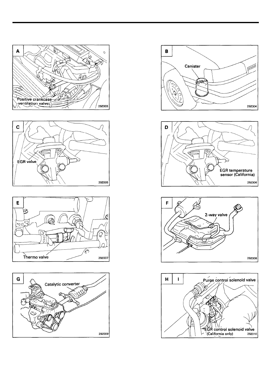
LOCATION OF EMISSION CONTROLS
2 9 - 4
GENERAL (MPI)
EMISSION CONTROL SYSTEMS
2 9 - 5
GENERAL (MPI)
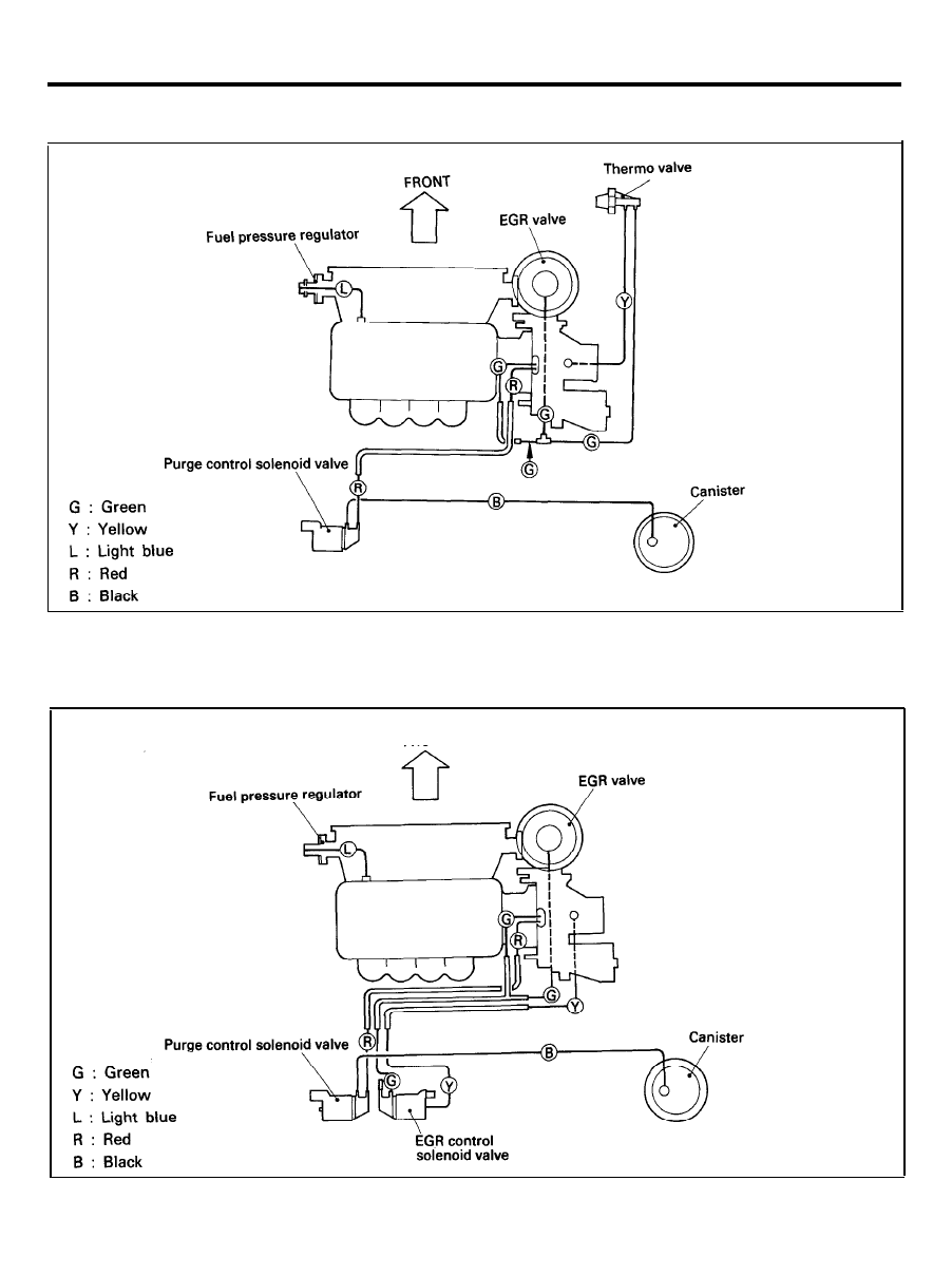
VACUUM HOSE LAYOUT (FEDERAL AND CANADA)
VACUUM HOSE LAYOUT (CALIFORNIA)
2 9 - 6
GENERAL (MPI)
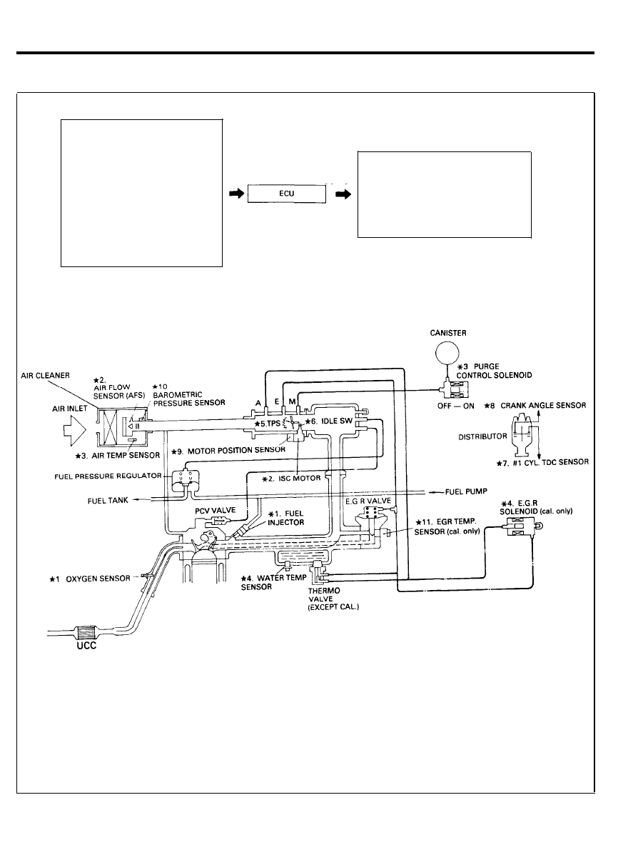
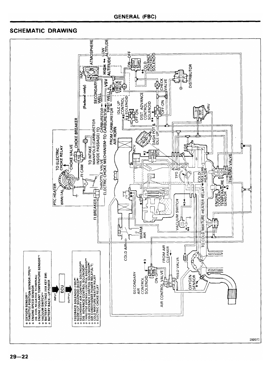
SCHEMATIC DRAWING
*1. Oxygen sensor
*2. Air-flow sensor
*3. Intake air temperature sensor
*4. Water temperature sensor
*5. Throttle position sensor
*6. Idle switch
*7. No. 1 cylinder TDC sensor
*8. Crankshaft angle sensor
*9. Motor position sensor
*10. Barometric pressure sensor
Battery voltage
Vehicle speed sensor
Cooler load signal
Starter “S” terminal
Power steering sw
*11. EGR temperature sensor (Cal. only)
INPUT
OUTPUT
*1. Injector
*2. ISC motor
*3. Purge control solenoid valve
*4. EGR solenoid valve (Cal. only)
Fuel pump control (control relay)
Air conditioner power relay
Ignition timing control
D i a g n o s i s
Emission lamp (Except Canada)
TDC : Top Dead Center
A/T : Vehicles witch automatic transaxle
PCV : Positive Crankcase Ventilation
UCC : Underfloor Catalytic Converter
CAL : California
2 9 - 7
CRANKCASE EMISSION CONTROL SYSTEM
1.
2.
3.
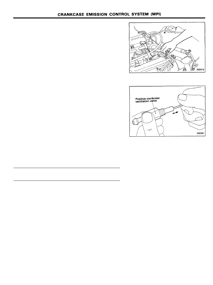
Disconnect the ventilation hose from the positive crankcase
ventilation (PCV) valve. Remove the PCV valve from the
rocker cover and reconnect it to the ventilation hose.
Run the engine at idle and put a finger on the open end of
the PCV valve and make sure that intake manifold vacuum
is
felt.
NOTE
The plunger inside the PCV valve will move back and forth.
If vacuum is not felt, clean the PCV valve and ventilation
hose in cleaning solvent or replace if necessary.
INSPECTION
1. Remove the positive crankcase ventilation valve.
2. Insert a thin stick into the positive crankcase ventilation
valve from the threaded side to check that the plunger
moves.
3. If the plunger does not move, the positive crankcase
ventilation valve is clogged. Clean it or replace.
INSTALLATION
Install the positive crankcase ventilation valve and tighten to
specified torque.
PCV valve tightening torque . . . . . . . . . . . . . . . . . . . .
8-12 Nm (80-120 kg.cm, 5.8-8.7 lb.ft)
2 9 - 8
EVAPORATIVE EMISSION CONTROL SYSTEM (MPI)
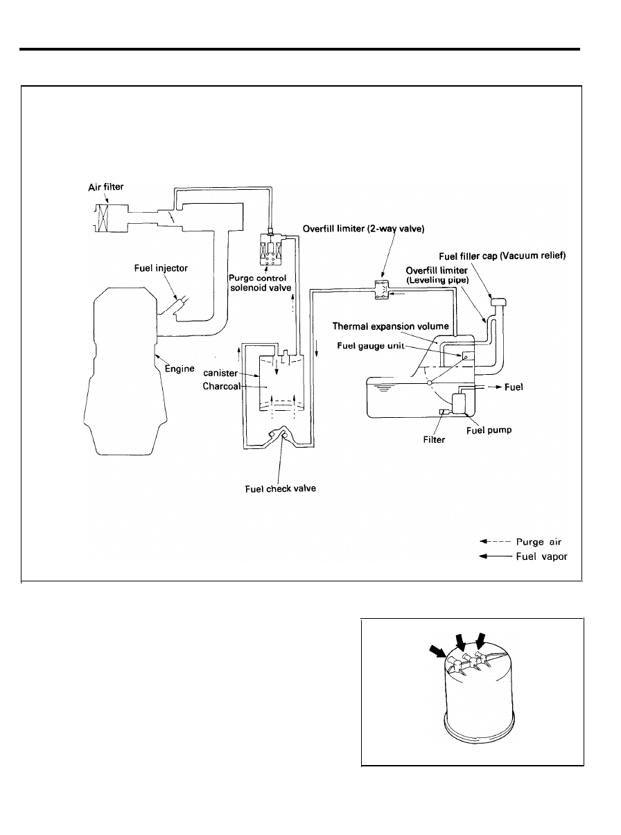
EVAPORATIVE EMISSION CONTROL SYSTEM
COMPONENTS
CANISTER
Inspection
1. Look for loose connections, sharp bends or damage to the
fuel vapor lines.
2. Look for distortion, cracks or fuel leakage.
3. After removing the charcoal canister, inspect for cracks or
damage.
2 9 - 9
EVAPORATIVE EMISSION CONTROL SYSTEM (MPI)
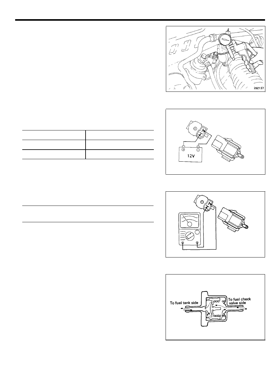
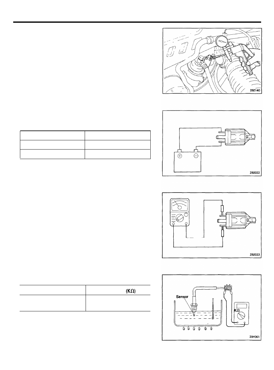
PURGE CONTROL SOLENOID VALVE
Inspection
NOTE
When disconnecting the vacuum hose, make an identification
mark on it so that it can be reconnected to its original position.
1.
Disconnect the vacuum hose (black with red stripe) from the
solenoid valve.
2. Detach the harness connector.
3. Connect a vacuum pump to the nipple to which the
red-striped vacuum hose was connected.
4. Apply vacuum and check when voltage is applied to the
purge-control solenoid valve and when the voltage is
discontinued.
Battery voltage
Normal condition
When applied
Vacuum is released.
When discontinued
Vacuum is maintained.
5. Measure the resistance between the terminals of the
solenoid valve.
Purge control solenoid valve
Coil resistance . . . . . . . . . . . . . . 36-44fl [at 20°C (68°F)]
OVERFILL LIMITER (TWO-WAY VALVE)
To inspect the overfill limiter (Two-way valve), refer to Group
31-Fuel tank.
2 9 - 1 0
EVAPORATIVE EMISSION CONTROL SYSTEM (MPI)
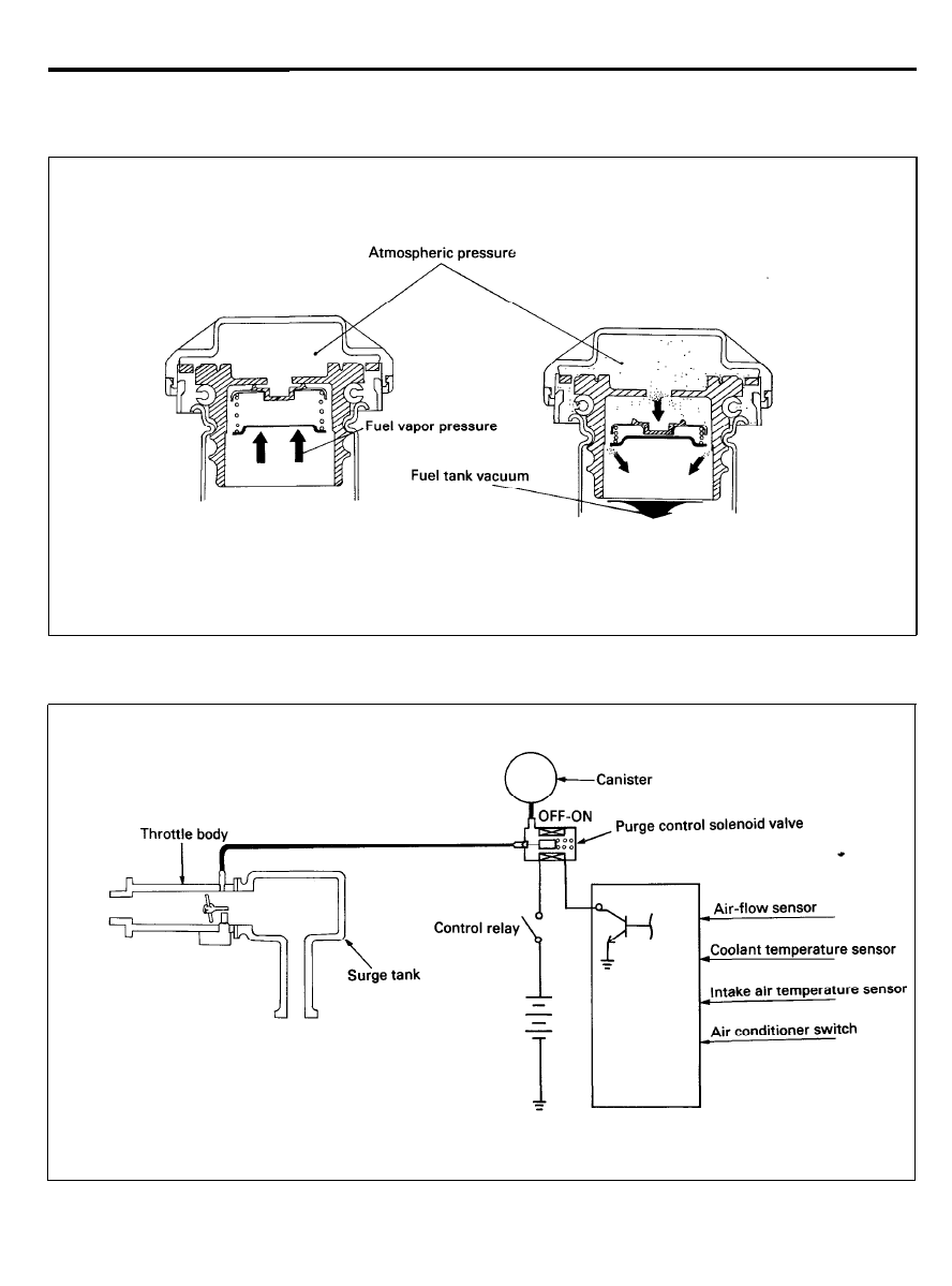
FUEL FILLER CAP
The fuel filler cap is equipped with a vacuum relief valve to prevent the escape of fuel vapor into the atmosphere.
When pressure is in fuel tank
When vacuum is in fuel tank
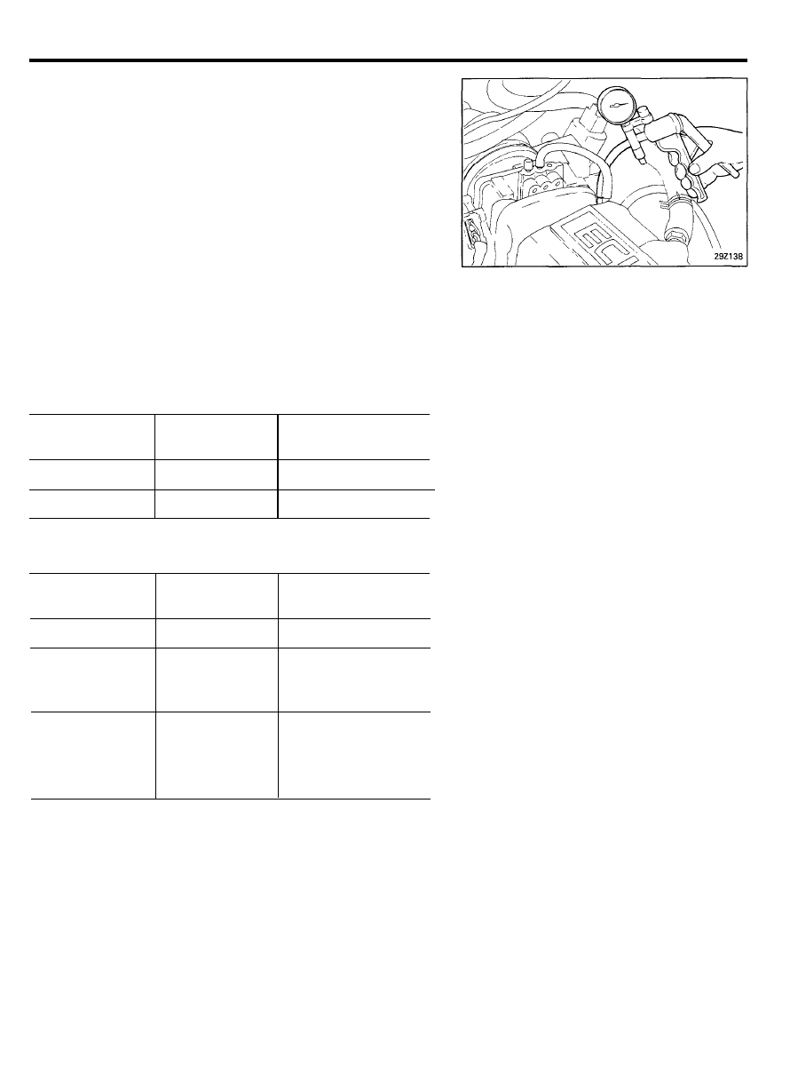
CHECKING PURGE CONTROL SYSTEM
2 9 - 1 1
EVAPORATIVE EMISSION CONTROL SYSTEM (MPI)
Checking
1. Disconnect the vacuum hose (red stripe) from the throttle
body, and connect a vacuum pump to the vacuum hose.
2.
Check the following points when the engine is cold [coolant
temperature 60°C (140°F) or below] and when it is warm
[coolant temperature 70°C (158°F) or higher].
When engine is cold
Engine operating
condition
Applying vacuum Result
Idling
3,000 rpm
50 kPa (7.3 psi)
Vacuum is held
When engine is warm
Engine operating
condition
Apply vacuum
Result
Idling
50 kPa (7.3 psi)
Vacuum is held
Within 3 minutes Try to apply
Vacuum is released
after engine start vacuum
3,000 rpm
After 3 minutes
50 kPa (7.3 psi)
Vacuum will be held
have passed after
momentarily, after
engine start
which, it will be
3,000 rpm
released.
2 9 - 1 2

EXHAUST EMISSION CONTROL SYSTEM (MPI)
EXHAUST EMISSION CONTROL SYSTEM
Exhaust emissions (CO, HC, NOx) are controlled by a combination
of engine modifications and the addition of special control
components.
Modifications to the combustion chamber, intake manifold,
camshaft and ignition system form the basic control system.
Additional control devices include an exhaust gas recirculation
(EGR) system and catalytic converters.
These systems have been integrated into a highly effective
system which controls exhaust emissions while maintaining
good driveability and fuel economy.
AIR/FUEL MIXTURE RATIO CONTROL SYSTEM
[Multi Point Injection (MPI) System]
The MPI system is a system which employs the signals from the
oxygen sensor to activate and control the injector installed in the
manifold for each cylinder, thus precisely regulating the air/fuel
mixture ratio and reducing emissions.
This in turn allows the engine to produce exhaust gases of the
proper composition to permit the use of a three-way catalyst. The
three-way catalyst is designed to convert the three pollutants (1)
hydrocarbons (HC), (2) carbon monoxide (CO), and (3) oxides of
nitrogen (NOx) into harmless substances. There are two
operating modes in the MPI system.
1. Open-Loop air/fuel ratio is controlled by information
programmed into the ECU.
2. Closed-Loop air/fuel ratio is varied by the ECU based on
information supplied by the oxygen sensor.
2 9 - 1 3
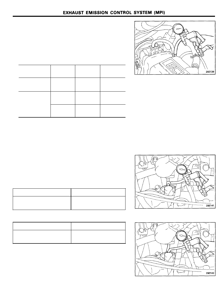
EXHAUST GAS RECIRCULATION SYSTEM
Inspection (Federal, Canada)
1.
Disconnect the vacuum hose (green stripe) from the throttle
body, and connect a vacuum pump to the vacuum hose.
2. Check the following points when the engine is both cold
[coolant temperature 50°C (122°F) or below] and hot
[Coolant temperature 80-95°C (176-205°F) or higher].
Engine coolant
Vacuum
Engine
Normal
temperature
condition
condition
Cold
Apply
Idling
Vacuum is
released
6 kPa
Idling
Vacuum is
Hot
(1.7 in.Hg)
held
26 kPa
Idle is
Vacuum is
(7.5 in.Hg)
unstable
held
Inspection (California Only)
1. Disconnect the vacuum hose (green stripe) from the EGR
valve body, and connect a vacuum pump via the three way
terminal.
2. Check the following points when the engine is both cold
[coolant temperature 20°C (68°F) or below] and warm
[Coolant temperature 70°C (158°F) or higher].
[When the engine is cold]
Engine condition
Normal condition
Rev engine
No change in vacuum
(atmospheric pressure)
[When the engine is warm]
Engine condition
Normal condition
Rev engine
Vacuum rises temporarily to
14 kPa (3.9 in.Hg) or more.
3. Disconnect the three-way terminal and connect the hand
vacuum pump directly to the Exhaust Gas Recirculation
(EGR) valve.
4. Check whether the engine stalls or the idling is unstable
when a vacuum of 26 kPa (7.5 in.Hg) or higher is applied
during idling.
2 9 - 1 4
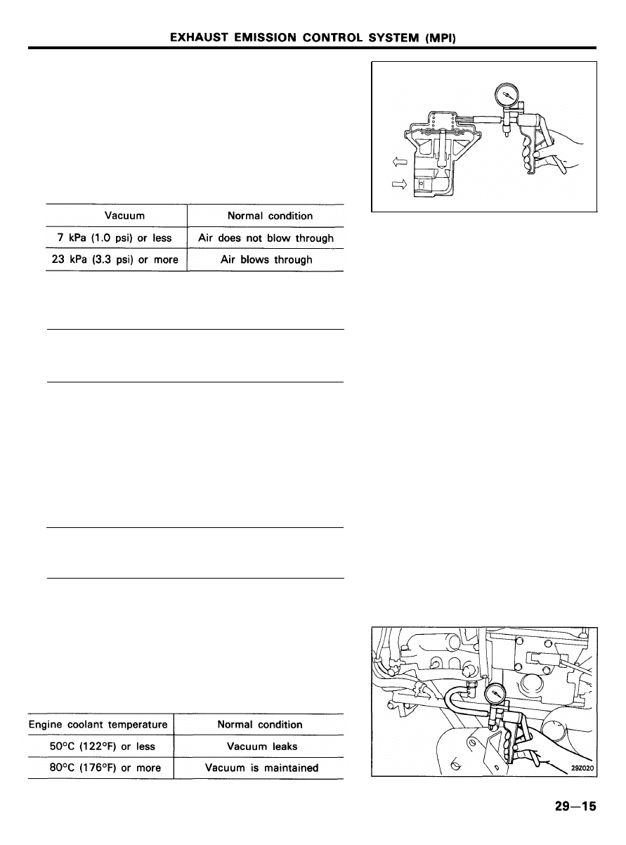
EGR Valve
1. Remove the EGR valve and check for sticking, carbon
deposits, etc.
If such conditions exist, clean with solvent to ensure tight
valve seat contact.
2. Connect a manual vacuum pump to the EGR valve.
3.
Apply a vacuum of 67 kPa (9.7 psi) and check air tightness.
4.
Blow in air from one passage of the EGR to check condition
as follows.
CAUTION
When installing the EGR valve, use a new gasket and
tighten to the specified torque.
Tightening torque
E G R v a l v e . . . . . . . . . . . . . . . . . . . . . .
1 9 - 2 7 N m ( 1 9 0 - 2 8 0 k g . c m , 1 4 - 2 0 l b . f t )
Thermo Valve (Federal and Canada Vehicles Only)
CAUTION
1. Do not use a wrench on the plastic section when
removing or installing the thermo valve.
2. When installing, apply a coat of sealant to the threads,
and tighten to the specified torque.
Tightening torque
Thermo valve . . . . . . . . . . . . . . . . . . . . . . .
2 0 - 3 9 N m ( 2 0 0 - 4 0 0 k g . c m , 1 4 - 2 9 l b . f t )
3. When disconnecting the vacuum hose, make an
identification mark on it so that it can be reconnected
to the original position.
1. Disconnect the vacuum hoses (yellow stripe and green
stripe) from the thermo valve, and connect a manual vacuum
pump to the thermo valve.
2. Apply a vacuum and check the air passage through the
thermo valve.
EXHAUST EMISSION CONTROL SYSTEM (MPI)
EGR Control Solenoid Valve (California only)
NOTE
When disconnecting the vacuum hose, make an identification
mark on it so that it can be reconnected to its original position.
1.
Disconnect the vacuum hose (green stripe) from the solenoid
valve.
2. Disconnect the harness connector.
3. Connect a hand vacuum pump to the nipple to which the
green-striped vacuum hose was connected.
4.
5.
Apply a vacuum to check for a maintained vacuum when
voltage applied directly to the EGR control solenoid valve.
When the voltage is discontinued, the vacuum is released.
Battery voltage
Result
When applied
Vacuum is held.
When discontinued
Vacuum is released.
Measure the resistance between the terminals of the
solenoid valve
Standard value: 36-44fl [at 20°C (68°F)]
EGR Temperature Sensor (California Vehicles Only)
1. Place the EGR temperature sensor in water, and then
measure the resistance value between terminals 1 and 2
while increasing the water temperature.
If out of specification, replace the EGR temperature sensor.
Temperature °C (°F)
Resistance
50 (122)
6 0 - 8 3
100 (212)
1 1 - 1 4
CATALYTIC CONVERTER
Refer to the page 00-9.
2 9 - 1 6

GENERAL (FBC)
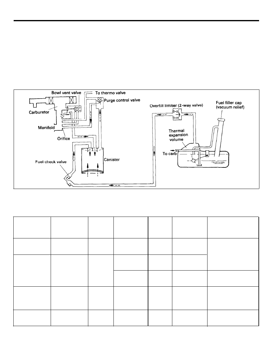
GENERAL
The emission control system has the following three major systems.
1. Crankcase emission control system.
The crankcase emission control system is a system adopting a closed-type crankcase ventilation to prevent
blow-by gases from escaping into the atmosphere. The blow-by gases in the crankcase are routed back to the
intake manifold for combustion.
2. Evaporative emission control system.
The evaporative emission control system prevents the emission of fuel vapour from the fuel tank, carburetor
into the atmosphere. It consists of various components (a canister, purge control valve, 2-way valve and so
no) which collect and lead fuel vapour to the combustion chamber for combustion.
3. Exhaust emission control system.
The exhaust emission control system consists of an air-fuel ratio control unit (FBC system), three way catalytic
converter, exhaust gas recirculation (EGR) system, secondary air supply system to reduce emission of CO, HC
and NOx.
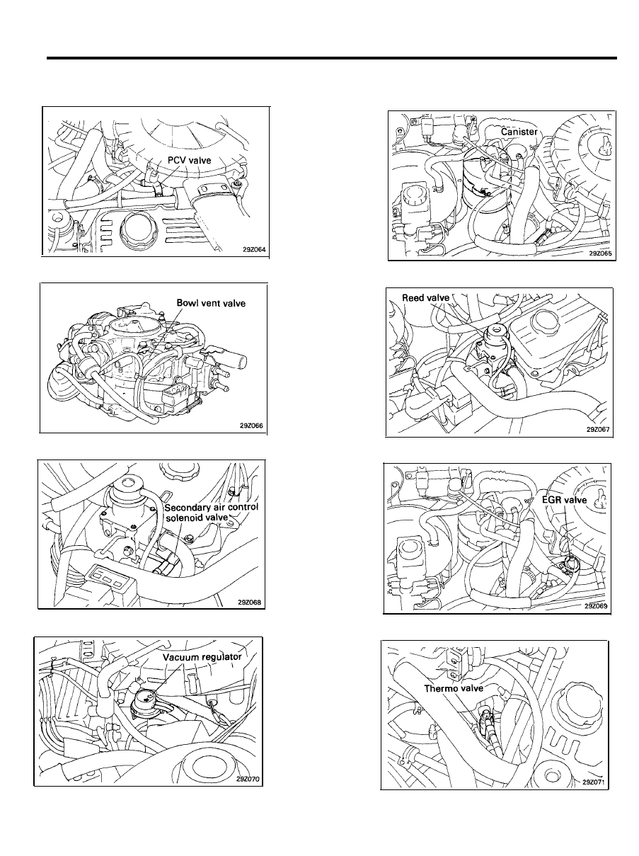
EMISSION CONTROL COMPONENTS
Components
Function
Crankcase Emission Control System
Positive crankcase ventilation (PCV) valve HC emission control
Evaporative Emission Control System
Canister
2-way valve (Overfill limiter)
Purge control valve (PCV)
HC emission control
Bowl vent valve (BW)
Fuel filler cap
Fuel check valve
Remarks
Variable flow rate type
Single diaphragm type
vacuum type
With relief valve
Exhaust Emission Control System
Jet air system
CO emission control
jet swirl type
FBC system (Air-fuel ratio control system) CO, HC, NOx emission control Oxygen sensor feedback type
Catalytic converter
CO, HC, NOx emission control Three-way type
Secondary air supply system
CO, HC emission control
Reed valve
With air control valve
Secondary air control solenoid valve
On-off solenoid valve
Exhaust gas recirculation system
NOx emission control
EGR valve
Single type
Vacuum regulator valve (VRV)
With vacuum control
Thermo valve
Wax pellet type
High altitude compensation system
CO, HC emission control
For Federal
High altitude compensator (HAC)
Bellows type
Heated air intake system
CO, HC emission control
Vacuum control type
Mixture control valve (MCV)
CO, HC emission control
Differential pressure type valve
FBC : Feedback Carburetor
2 9 - 1 7

GENERAL (FBC)
TROUBLESHOOTING
Symptom
Engine will not start
or is hard to start
(Cranking possible)
Rough idle or engine
stalls
Engine hesitates or
poor acceleration
Excessive oil
consumption
Poor fuel mileage
Probable cause
Mixture control valve kept open
Vacuum hose disconnected or damaged
EGR valve kept open
EGR valve kept open
High altitude compensation system faulty
Vacuum hose disconnected or damaged
Faulty purge control system
Faulty bowl vent valve
Mixture control valve kept open
Faulty PCV valve
Exhaust gas recirculation system faulty
High altitude compensation system faulty
Thermo valve faulty-cold engine
Intake air temperature control system faulty
Positive crankcase ventilation line clogged
Intake air temperature control system faulty
Exhaust gas recirculation system faulty
High altitude compensation system faulty
Remedy
Replace
Repair or replace
Repair or replace
Repair or replace
Troubleshoot the system and check
components under suspicion
Repair or replace
Troubleshoot the system and check
components under suspicion
Replace
Replace
Replace
Troubleshoot the system and check
each component under suspicion
Troubleshoot the system and check
components under suspicion
Replace
Troubleshoot the system and check
components under suspicion
Check positive crankcase ventilation
system
Troubleshoot the system and check
components under suspicion
Troubleshoot the system and check
components under suspicion
Troubleshoot the system and check
components under suspicion
2 9 - 1 8
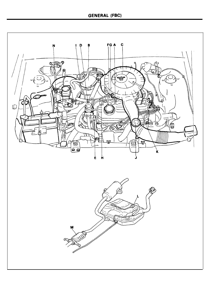
LOCATION OF EMISSION COMPONENTS
2 9 - 1 9
GENERAL (FBC)
EMISSION CONTROL SYSTEMS
A. PCV valve
B. Canister
C. Bowl vent valve (BVV)
E. Secondary air control solenoid valve
F. EGR valve
G. Vacuum regulator valve (VRV)
2 9 - 2 0
D. Reed valve
H. Thermo valve
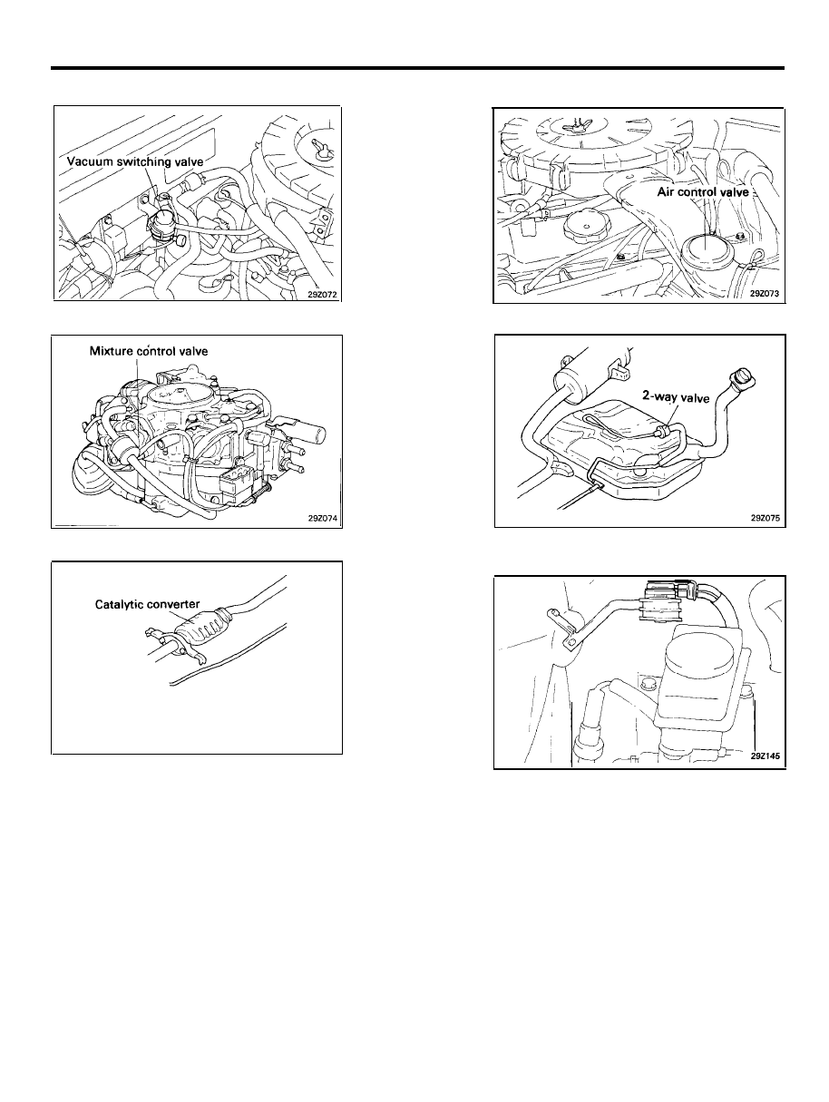
GENERAL (FBC)
I. Vacuum switching valve
K. Mixture control valve (MCV)
M. Catalytic converter
J. Air control valve
L. 2-way valve
N. High altitude compensator (HAC)
2 9 - 2 1
GENERAL (FBC)
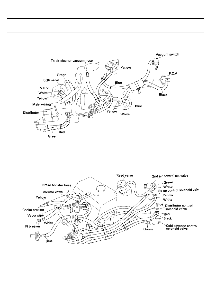
VACUUM HOSE INSTALLING (FOR CANADA)
2 9 - 2 3
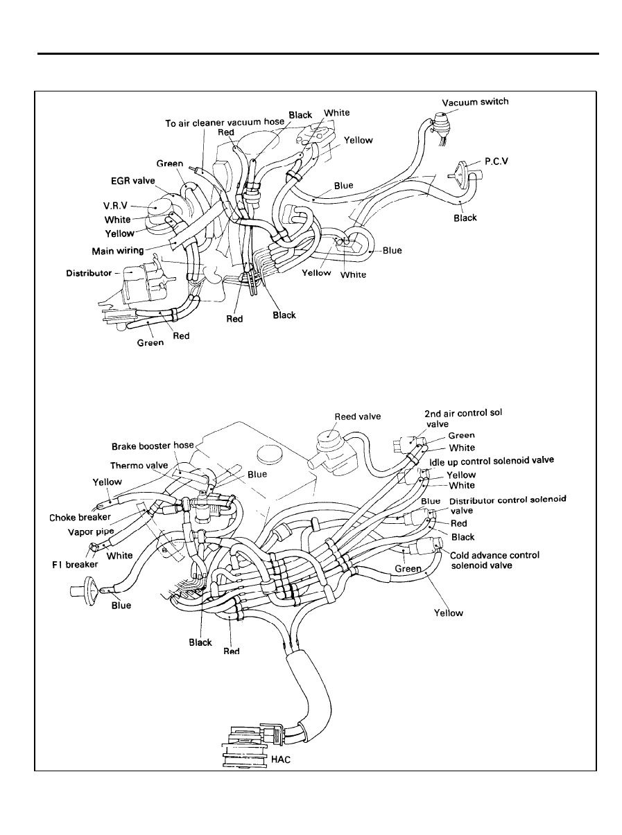
GENERAL (FBC)
VACUUM HOSE INSTALLING (FOR FEDERAL)
2 9 - 2 4
CRANKCASE EMISSION CONTROL SYSTEM (FBC)
CRANKCASE EMISSION CONTROL
SYSTEM
GENERAL DESCRIPTION
This closed-type crankcase emission control system is composed
of a positive crankcase ventilation (PCV) valve and related hoses.
This system prevents the blow-by gases from escaping into the
atmosphere. The blow-by gases, which are burned gases past
the piston rings during combustion. The exhaust gases include
HC, CO and NOx.
The system supplies fresh air to the crankcase through the air
cleaner. Inside the crankcase, the fresh air is mixed with blow-by
gases, which pass through the PCV valve into the induction
system.
The PCV valve has a metered orifice through which the mixture
of fresh air and blow-by gases are drawn into the intake manifold
in response to the intake manifold vacuum. The valve capacity
is adequate for normal driving conditions.
Under heavy acceleration of high-speed driving, there is less
intake manifold vacuum available, and the blow-by gases are
back up into the air cleaner through the breather hose.
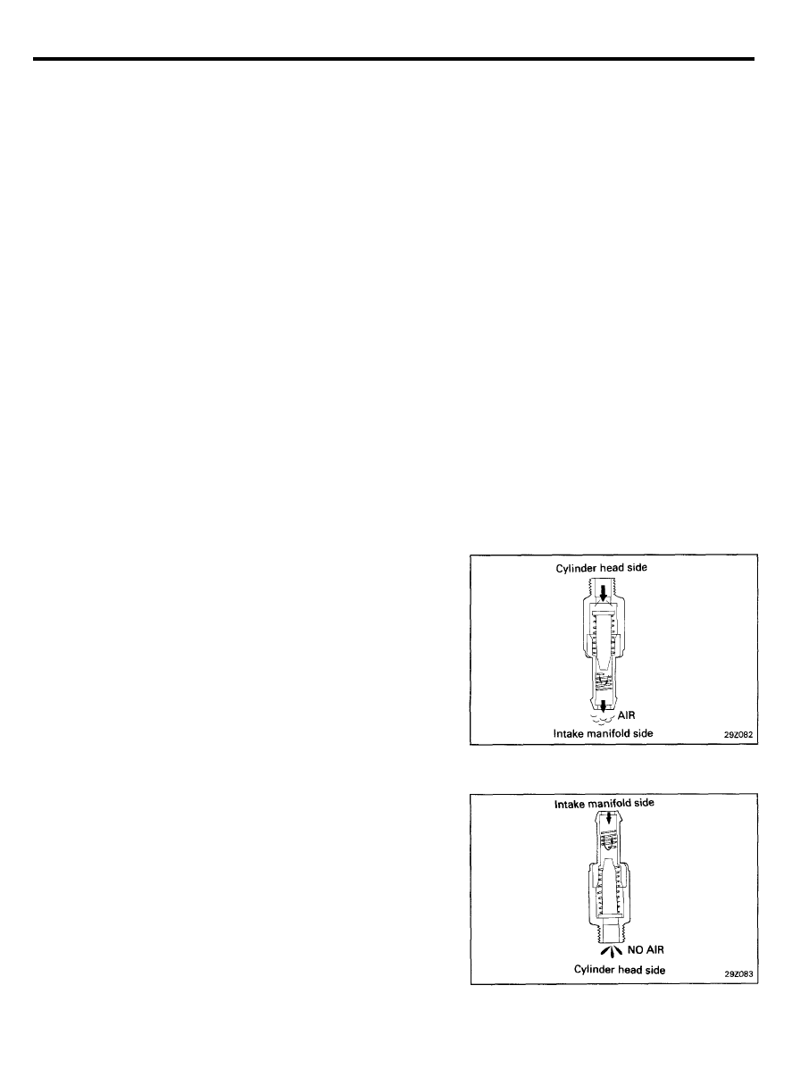
INSPECTION
1. Remove PCV valve from the rocker cover.
2. Attach a clean hose to the PCV valve cylinder head side.
3.
Check that the air passes through easily when you blow on
the PCV valve cylinder head side.
CAUTION
Do not suck air through the valve. Petroleum substances
inside the valve are harmful.
4.
Next, attach a clean hose to the PCV valve intake manifold
side.
5.
Check that air passes through with difficulty when you blow.
6. If the PCV valve fails either of the checks, replace it.
2 9 - 2 5
EVAPORATIVE EMISSION CONTROL SYSTEM (FBC)
EVAPORATIVE EMISSION CONTROL
SYSTEM
GENERAL DESCRIPTION
This evaporative emission control system is employed to prevent
the emission of fuel vapours from the fuel tank and the
carburetor, from being discharged into the atmosphere. And this
system consists of charcoal canister, a bowl vent valve, a purge
control valve.
Condition
Idle and
Below
low speed
63±3 (145±5)
High speed
driving
Above
65±2 (149±4)
High pressure
in fuel tank
High vacuum
in fuel tank
Coolant
temperature
°C (°F)
Thermo
valve
Open
Closed
Engine
rpm
Purge
control
valve
Check valve
in fuel filler
cap
Evaporated fuel
(HC)
-
Closed -
HC from fuel tank
is absorbed into the
Below 1450
rpm
Closed -
canister
Above 1450
Open
HC from canister is
-
rpm
led into carburetor
HC from fuel tank is
-
-
Closed
absorbed in the
canister
-
-
Open
Air is vented into the
fuel tank
2 9 - 2 6
EVAPORATIVE EMISSION CONTROL SYSTEM (FBC)
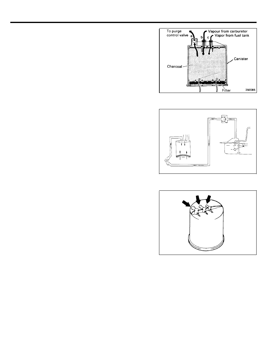
CANISTER
While the engine is inoperative, fuel vapours generated inside
the fuel tank and the carburetor float chamber are absorbed and
stored in canister.
When the engine is running, the fuel vapours absorbed in
canister are drawn into the intake manifold through the purge
control valve, and an orifice.
and the carburetor bowl vapours flow into the carburetor through
the bowl vent valve.
Inspection
1. Look for loose connections, sharp bends or damage in the
fuel vapour lines.
2. Look for deformation, cracks or fuel leakage.
3. After removing charcoal canister, inspect for cracks or
d a m a g e .
2 9 - 2 7
EVAPORATIVE EMISSION CONTROL SYSTEM (FBC)
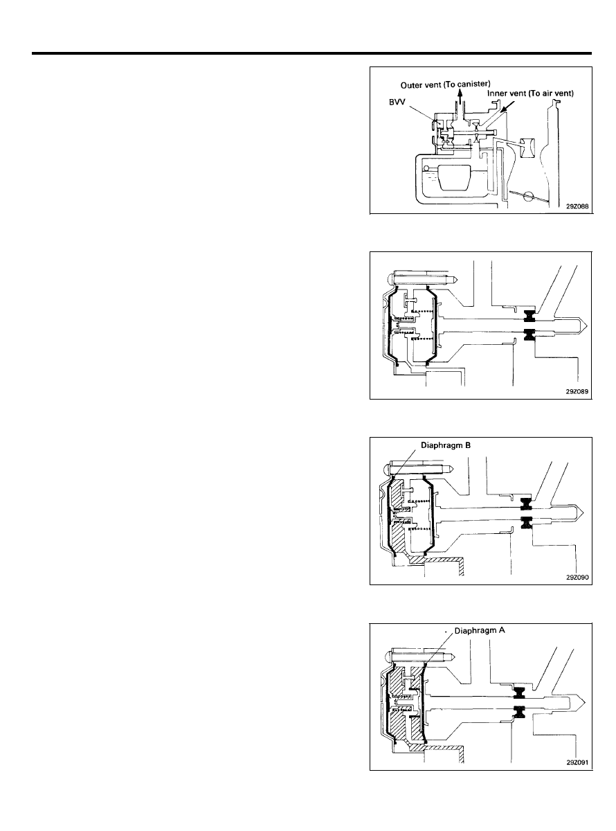
BOWL VENT VALVE
The bowl vent valve controls vapour in the carburetor bowl.
While the engine is running; the intake manifold vacuum acts
on the diaphragm to close the bowl vent valve so that the
carburetor bowl connects to the air vent.
When the engine stops, the bowl vent valve opens to connect
the carburetor bowl to the canister, causing fuel vapour to be
absorbed by the canister.
Operating Principle
1. When the engine is not running, fuel vapour flow to the
canister through outer vent passage (To canister). In this
condition, the valve closes to disconnect inner vent passage
(To air vent) by spring force.
2. When the intake manifold vacuum reaches more than 1.2
in.Hg (4 kPa, 0.6 psi) after the engine operating, diaphragm
B is pulled to right side and seat the valve as shown in
illustration.
3. In case of more than 50 mmHg, Diaphragm A is pulled to
left side and inner vent passage is opened.
NOTE
Even if the intake manifold vacuum decreases when the
engine is operating,
the check valve
always remains more
than 2.0 in.Hg (6.7 kPa, 1.0 psi) vacuum to maintain
atmospheric pressure at float chamber.
2 9 - 2 8
EVAPORATIVE EMISSION CONTROL SYSTEM (FBC)
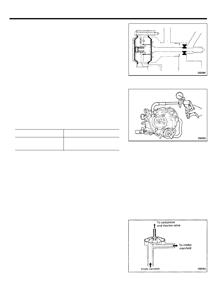
4. If intake manifold vacuum is less than 0.4 in.Hg (1.3 kPa,
0.2 psi) because of stopping the engine, diaphragm B gets
out of seat and diaphragm A is concurrently shifted to right
side causing inner vent passage to be disconnected.
Inspection
1. Remove the air cleaner.
2. Disconnect the bowl vapor hose from the bowl vent valve
(BVV) nipple and connect a hand vacuum pump to the BVV
to check the condition as follows.
3.
Apply a vacuum of 20 kPa (3.0 psi) to the BVV to check the
condition as follows.
Engine condition
Normal condition
Operating
Non-operating
CAUTION
Vacuum holding
Vacuum leaking
Check after the engine is cool. If the engine is not cold,
fuel may gush out from the BVV nipple.
PURGE CONTROL VALVE
The purge control valve is closed during idle to prevent vaporized
fuel from entering into the intake manifold. This is a particular
problem under high ambient temperatures condition. Once
ported vacuum exceeds the pre-set value, the purge control valve
is opened.
2 9 - 2 9
EVAPORATIVE EMISSION CONTROL SYSTEM (FBC)
Inspection
1. Remove the purge control valve.
2.
Connect a hand vacuum pump to the vacuum nipple of the
PCV.
3. Blow in air lightly from the canister side nipple to check
conditions as follows.
PCV operating vacuum . . . . . . . . . . . . . More than 1.4 in.Hg
Flow quantity . . . . . . . . . . . . . . . . . . . . . More than 35 lit/min
(At 3.3 in.Hg vacuum)
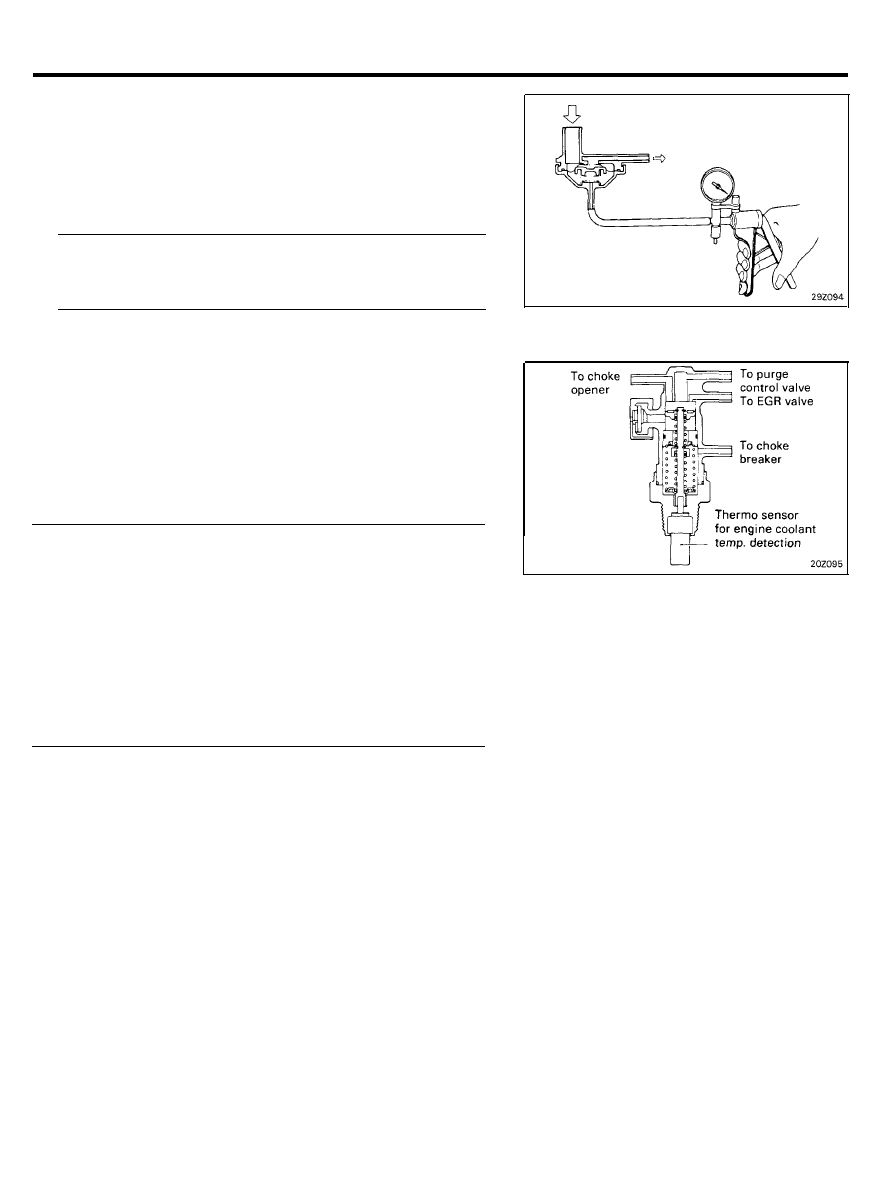
THERMO VALVE
The thermo valve, for sensing the engine coolant temperature
at the intake manifold, closes the purge control valve when the
engine coolant temperature is lower than the pre-set value.
This reduces CO and HC emissions under engine warm-up
conditions, and opens the purge control valve when the engine
coolant temperature is above the pre-set temperature.
Thermo valve opening temperature (To atmosphere)
Nipple to purge control valve . . . . . Below 63±3°C (145±5°F)
Nipple to EGR control valve . . . . . . Below 63±3°C (145±5°F)
Nipple to choke opener . . . . . . . . . . Below 63±3°C (145±5°F)
Nipple to choke breaker . . . . . . . . . . . Below 16±3°C (61±5°F)
Thermo valve closing temperature (To atmosphere)
Nipple to purge control valve . . . . . Above 65±2°C (149±4°F)
Nipple to EGR control valve . . . . . . Above 65±2°C (149±4°F)
Nipple to choke opener . . . . . . . . . . Above 65±2°C (149±4°F)
Nipple to choke breaker . . . . . . . . . . . Above 18±2°C (64±4°F)
Inspection
NOTE
This thermo valve also controls the choke breaker, EGR and
choke opener.
CAUTION
1) When removing or installing the thermo valve, do not use
wrenches or other tools on the resin part.
2) When installing, apply sealant to the threads and tighten
to 20 to 39 Nm (14 to 29 lb.ft)
3) When disconnecting the vacuum hose, put a mark on the
hose so that it may be reconnected at original position.
2 9 - 3 0
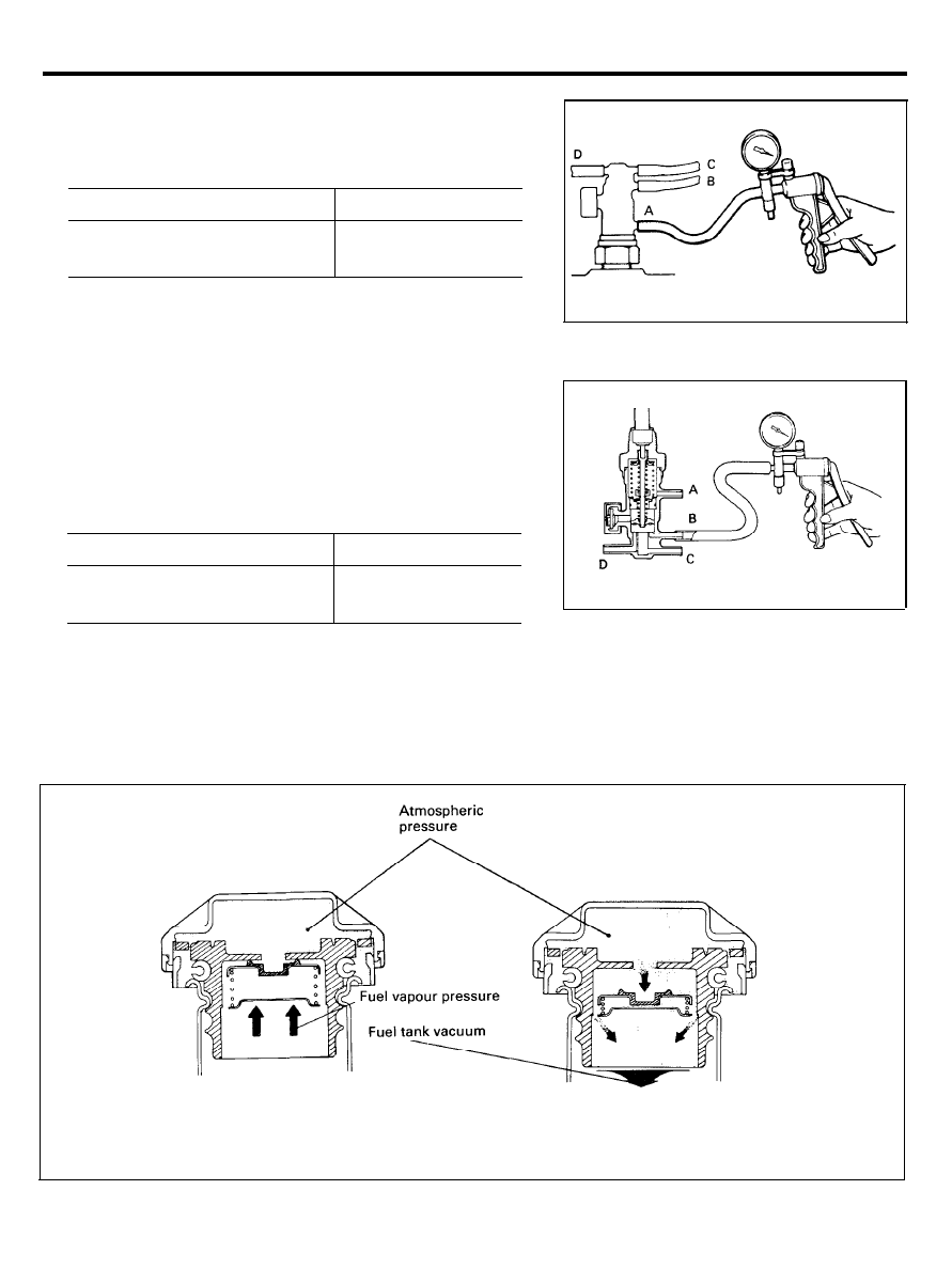
EVAPORATIVE EMISSION CONTROL SYSTEM (FBC)
1. Disconnect the vacuum hose connected to nipple (A) from
the thermo valve and connect a hand vacuum pump to the
nipple (A).
2.
Apply vacuum to check thermo valve conditions as follows.
Engine coolant temperature
Below 16±3°C (61±5°F)
Above 18±2°C (64±4°F)
Normal condition
Vacuum leaks
Vacuum holds
3.
4.
Disconnect all vacuum hoses from the thermo valve.
Connect a hand vacuum pump to nipple (B) to (C) or (D) and
apply vacuum to check thermo valve condition as follows.
NOTE
Plug nipples other than one to which the hand vacuum
pump is connected.
Engine coolant temperature
Normal condition
Below 63±3°C (145±5°F)
Above 65±2°C (149±4°F)
Vacuum leaks
Vacuum holds
FUEL FILLER CAP
The fuel filler cap is equipped with a vacuum relief valve to
prevent the escape of fuel vapour into the atmosphere.
When pressure is in fuel
tank
When vacuum is in fuel
tank
2 9 - 3 1
EVAPORATIVE EMISSION CONTROL SYSTEM (FBC)
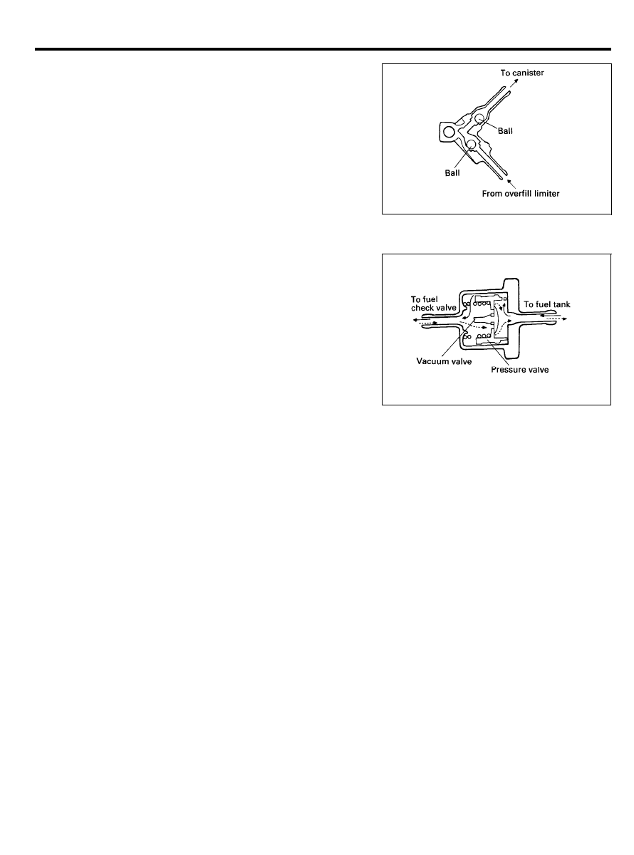
FUEL
CHECK VALVE
The fuel check valve is used to prevent fuel leaks, when the car
suddenly roll over. This valve is connected in the fuel vapor line
(between canister and overfill limiter) and is mounted on the
firewall.
The fuel check valve contains two balls as shown in the
illustration. Under normal conditions, the gasoline vapour
passage in the valve is opened, but if roll-over occurs one of the
balls closes the fuel passage, thus preventing fuel leakage.
OVERFILL LIMITER (TWO-WAY VALVE)
The overfill limiter consists of a pressure valve and a vacuum
valve. The pressure valve is designed to open when the fuel tank
internal pressure has increased over the normal pressure and
the vacuum valve opens when a lower pressure exit in the tank.
2 9 - 3 2

EXHAUST EMISSION CONTROL SYSTEM (FBC)
EXHAUST EMISSION CONTROL SYSTEM
GENERAL DESCRIPTION
Exhaust emission (CO, HC, NO) are controlled by a combination
of engine modifications and the addition of special control
components.
Modifications to the combustion chamber, intake manifold,
carburetor and ignition system form the basic control system.
Additional control devices include a jet air system, an exhaust
gas recirculation (EGR) system, catalytic converters, a secondary
air supply system, a dash pot, a heated air intake system. These
systems have been integrated into a highly effective system
which controls exhaust emissions while maintaining good
driveability and fuel economy.
2 9 - 3 3
EXHAUST EMISSION CONTROL SYSTEM (FBC)
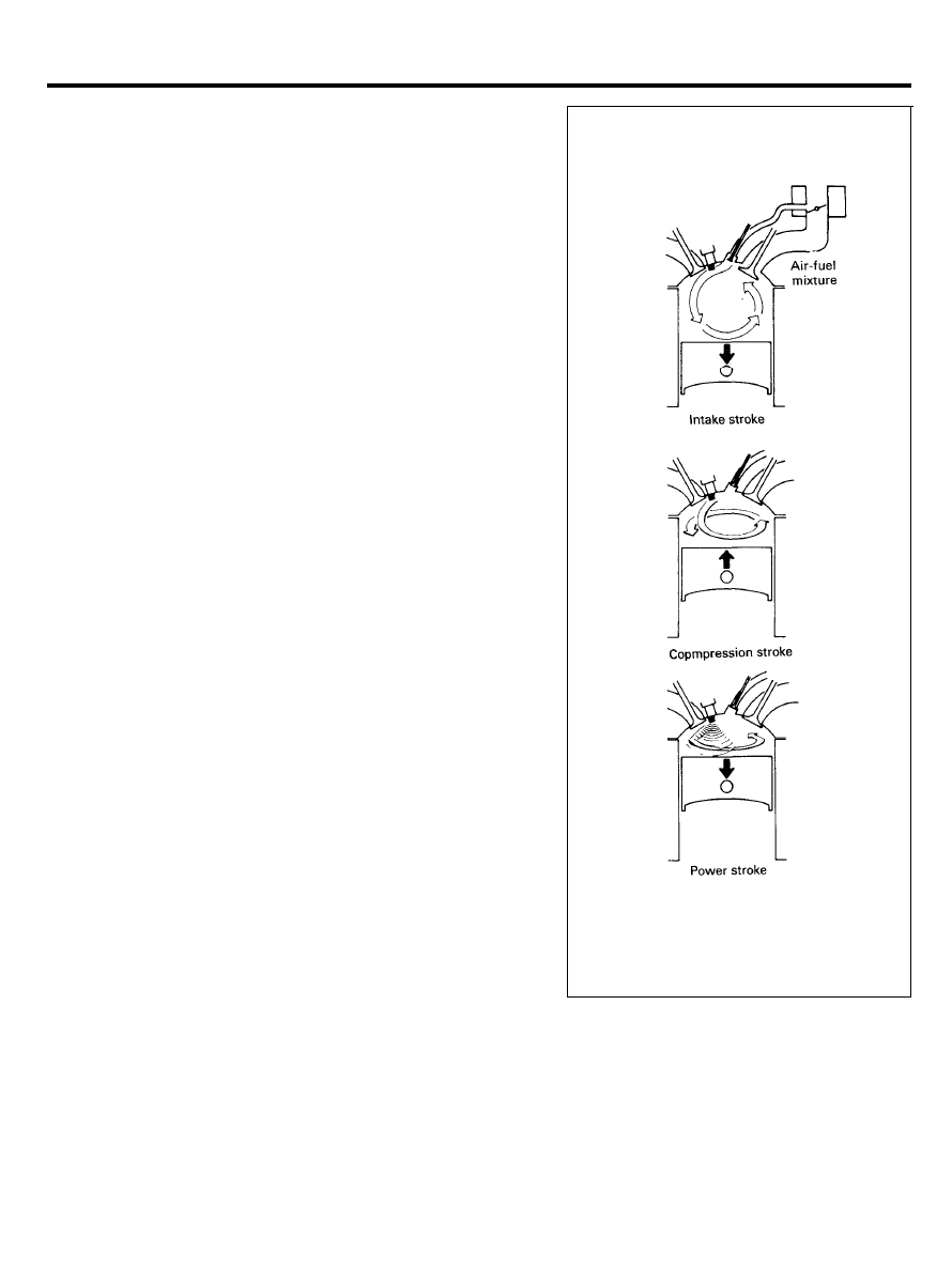
JET AIR SYSTEM
The combustion chamber is a cross-flow type hemispherical
combustion chamber. In addition to the intake valve and exhaust
valve, a jet valve which provides a super lean mixture or air into
the combustion chamber. The jet valve assembly consists of the
jet valve, jet body and spring and is screwed into the jet piece
which is press-fitted in the cylinder head with its jet opening
toward the spark plug.
A jet air passage is provided in the carburetor, intake manifold
and cylinder head. Air flows through the intake openings
provided near the primary throttle valve of the carburetor then
through the passage in the intake manifold and cylinder head,
and finally through the jet valve and the jet opening into the
combustion chamber.
The jet valve is actuated by the same cam as the intake valve
and by a common rocker arm so that the jet valve and intake
valve open and close almost simultaneously.
On the intake stroke, the air-fuel mixture flows through the
intake valve port into the combustion chamber. At the same time,
jet air flows into the combustion chamber because of the
pressure difference produced between the two ends of the jet
air passage (between the jet air intake openings in the carburetor
throttle bore and the jet opening of the jet piece) as the piston
moves down.
When the throttle valve opening is small during idle or light load,
a large pressure difference is produced as the piston goes down,
causing jet air to flow into the combustion chamber rapidly. The
jet air flowing out of the jet opening scavenges the residual
gases around the spark plug and promotes a good ignition. This
strong swirl in the combustion chamber continues throughout
the compression stroke and improves flame propagation after
ignition, assuring high combustion efficiency.
When the throttle valve opening increases, more air-fuel mixture
is drawn in from the intake valve port so that the pressure
difference is reduced and less jet air is drawn in.
The jet air swirl dwindles with increased throttle valve opening.
2 9 - 3 4
EXHAUST EMISSION CONTROL SYSTEM (FBC)
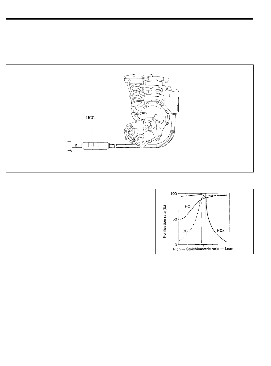
CATALYTIC CONVERTERS
A monolithic type three way catalytic converter is used to reduce
vehicle emission. The converter working in combination with the
air-fuel ratio feedback control oxidizes CO and HC and reduces
NOx.
UCC : Underfloor Catalytic Converter
Function
The three way catalytic converter removes CO, HC and NOx most
effectively in the vicinity of the stoichiometric ratio.
The air-fuel ration feedback from in the oxygen sensor, controls
the air-fuel mixture to the stoichiometric ratio. The catalytic
converter promotes both oxidation and reduction of resultant
exhaust gas to make it clean before it is released to atmosphere.
CAUTION
The catalytic converters require the use of unleaded gasoline
only. Leaded gasoline will destroy the effectiveness of the
catalysts as an emission control device.
Under normal operating conditions, the catalytic converters
will not require maintenance. However, it is important to keep
the engine properly tuned. If the engine is not kept properly
tuned, the catalytic converter may overheat. This situation can
also occur during diagnostic testing if any spark plug cables
are removed and the engine is allowed to run for a prolonged
period of time.
2 9 - 3 5
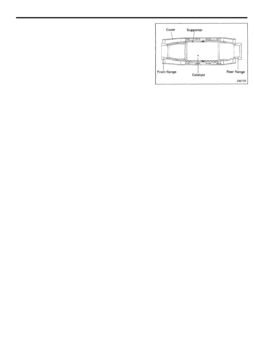
EXHAUST EMISSION CONTROL SYSTEM (FBC)
Underfloor Catalytic Converter (UCC)
This type catalytic converter looks like a muffler. It mainly
promotes the oxidation of HC, CO.
FEEDBACK CARBURETOR (FBC) SYSTEM
(AIR-FUEL RATIO CONTROL SYSTEM)
The FBC system is essentially an emission control system which
utilizes an electronic signal, generated by an exhaust gas oxygen
sensor to precisely control the air-fuel mixture ratio in the
carburetor. This in turn allows the engine to produce exhaust
gases of the proper composition to permit the use of a
three-way catalyst.
The three-way catalyst is designed to convert the three
pollutants (HC, CO and NOx) into harmless substances.
There are two operating modes in the FBC system:
1. Open Loop
Air fuel ratio is controlled by information programmed into
the ECU.
2. Closed Loop
Air fuel ration is varied by the ECU based on information
supplied by the oxygen sensor.
2 9 - 3 6
EXHAUST EMISSION CONTROL SYSTEM (FBC)
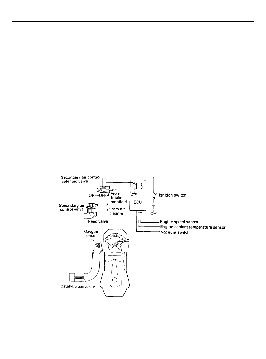
SECONDARY AIR SUPPLY SYSTEM
The secondary air supply system consists of a reed valve, a
secondary air control valve, a secondary air control solenoid
valve, an ECU
and
sensors.
The reed valve supplies secondary air into the exhaust manifold
for the purpose of promoting oxidation of exhaust emissions
during the engine warm-up, deceleration and hot start operation.
The reed valve is actuated by exhaust vacuum from pulsations
in the exhaust manifold. Additional air is supplied into the
exhaust manifold through the secondary air control valve.
The secondary air control valve is opened by the intake manifold
vacuum when the solenoid valve is energized by the ECU based
on information on coolant temperature, engine speed, time and
idle position.
2 9 - 3 7
EXHAUST EMISSION CONTROL SYSTEM (FBC)
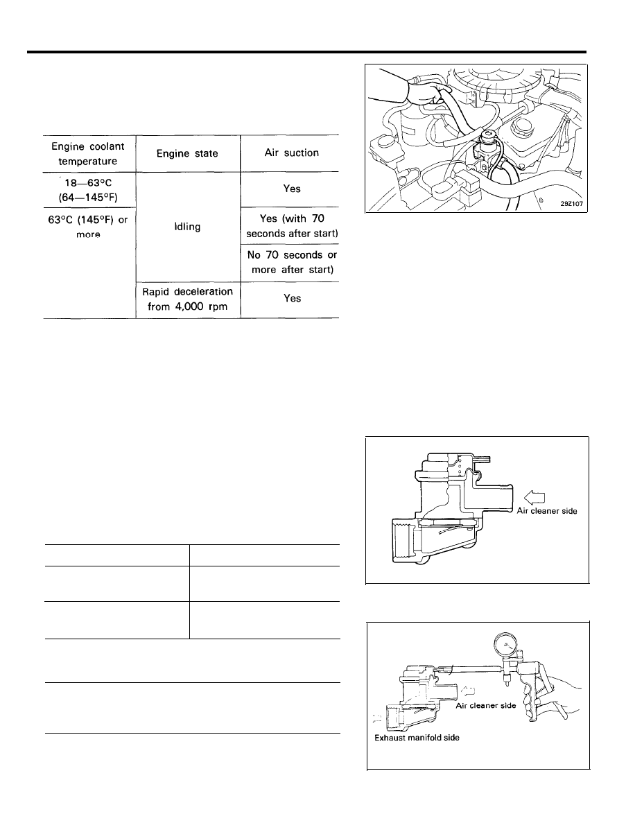
Inspection
air supply hose.
1. Disconnect the air supply hose from the air cleaner and
check for vacuum by placing your thumb over the end of the
CAUTION
Note that if secondary air control valve is broken, emission
may blow back.
2. Remove the secondary air control valve.
3.
Blow in air from the air cleaner side of the valve to check
that air does not flow.
4.
Connect a hand vacuum pump to the secondary air control
valve nipple.
5. Apply a vacuum of 5.9 in.Hg (20 kPa, 3.0 psi) and blow in
air to check condition as follows.
Air blow direction
Normal condition
Air cleaner side to
exhaust manifold side
Air blows through
Exhaust manifold side to
air cleaner side
Air does not blow through
6.
If any fault is found in above checks, replace the secondary
air control valve.
Tightening torque
Secondary air control valve . . . . . . . . . . . . . . . . . . . . . . . . . . .
50-60 Nm (510-610 kg.cm, 37-44 ft.lbs.)
2 9 - 3 8
EXHAUST EMISSION CONTROL SYSTEM (FBC)
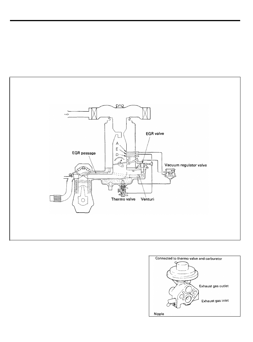
EXHAUST GAS RECIRCULATION SYSTEM
Exhaust Gas Recirculation (EGR) system is designed to reduce
oxides of nitrogen in the vehicle exhaust.
In this system, the exhaust gas is partially recirculated from an
exhaust port in the cylinder head into a port located at the intake
manifold. The EGR flow is controlled by an EGR control valve,
a vacuum regulator vale (VRV), and a thermo valve.
EGR Valve
EGR valve is a venturi pressure type. It is controlled by a ported
vacuum signal from the carburetor by way of vacuum regulator
valve (VRV) in response to the throttle valve openings. The EGR
flow is suspended at idle and wide open throttle operations due
to a low ported vacuum.
2 9 - 3 9
EXHAUST EMISSION CONTROL SYSTEM (FBC)
EGR Valve Inspection
1. Remove the EGR vale and check if for sticking, deposit of
carbon, etc.
If such condition exists, clean with adequate solvent to
ensure tight valve seat contact.
2. Connect a hand vacuum pump to the EGR valve.
3. Apply a vacuum of 19.8 in.Hg (67 kPa, 10 psi) and check
air tightness.
4.
Blow in air from one passage of the EGR to check condition.
CAUTION
When installing the EGR valve, use a new gasket and
tighten to 19-27 Nm (190-280 kg.cm, 14-20 lb.ft.)
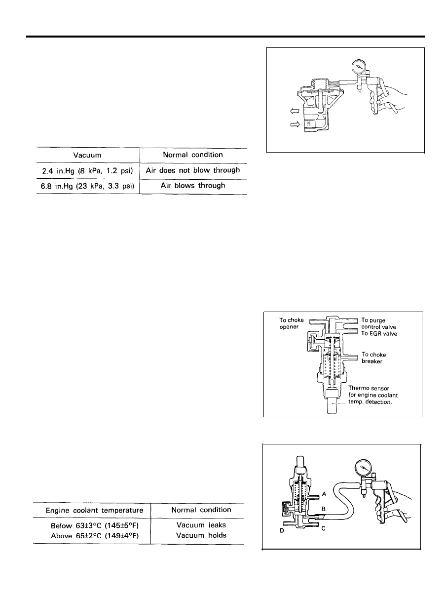
Thermo Valve
Thermo valve in the EGR vacuum supply line is a switch
sensitive to engine temperature. Thermo valve eliminates the
vacuum signal to the EGR valve during warm-up when less NOx
is generated.
Thermo Valve Inspection
1. Disconnect all vacuum hoses from the thermo valve.
2. Connect a hand vacuum pump to nipple (B) and apply
vacuum to check thermo valve condition as follows.
NOTE
Plug nipples other than one to which the hand vacuum
pump is connected.
2 9 - 4 0
EXHAUST EMISSION CONTROL SYSTEM (FBC)
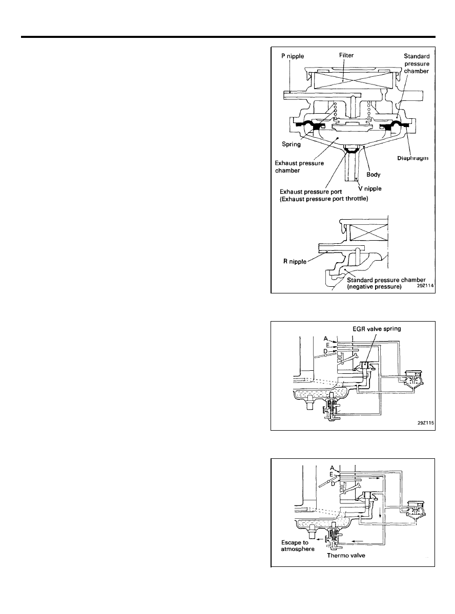
Vacuum Regulator Valve (VRV)
The vacuum signal to the EGR valve is modulated by a vacuum
regulator valve. The vacuum regulator valve reduces the EGR
vacuum signal by air bleed within the vacuum regulator valve
when the pressure applied to the regulator valve is lower than
the pre-set value (i.e. low engine load operation).
The pressure applied to the regulator valve is the total pressure
of exhaust pressure and venturi vacuum.
The air bleed is closed when the pressure applied to the vacuum
regulator valve is higher than the per-set value (i.e. high engine
load operation) and the EGR valve motion responds to an
unmodified vacuum signal.
Operating Principle
1. During Idle or Throttle Wide Open Operation
In this case, the E port vacuum is low and the EGR valve
is closed by spring force. As a result, EGR gas does not flow.
NOTE
The EGR is closed to ensure stable idle operation.
2. When Engine Coolant is Cold
In this case, the thermo valve opens to allow the E port
vacuum to escape to atmosphere. As a result, the EGR valve
does not operate.
NOTE
The EGR is shut off to secure driveability when the engine
is cold.
2 9 - 4 1
EXHAUST EMISSION CONTROL SYSTEM (FBC)
3. During Light to Moderate Load Operation
1) As the throttle valve is opened, the E port vacuum
increases to overcome the spring force of the EGR valve.
as a result, the EGR valve opens allowing exhaust gas
to recirculate to the intake manifold, causing a drop in
venturi vacuum.
2) When the venturi pressure drops to near the atmos-
pheric pressure, the VRV opens to allow the E port
vacuum to escape to atmosphere allowing the EGR valve
closes.
By repeating this cycle (closed loop control), EGR flow
rate proportional to the intake air volume can be
obtained.
NOTE
By controlling the EGR rate to optimum level, exhaust
emission (NOx) is minimized without loss of drivea-
bility.
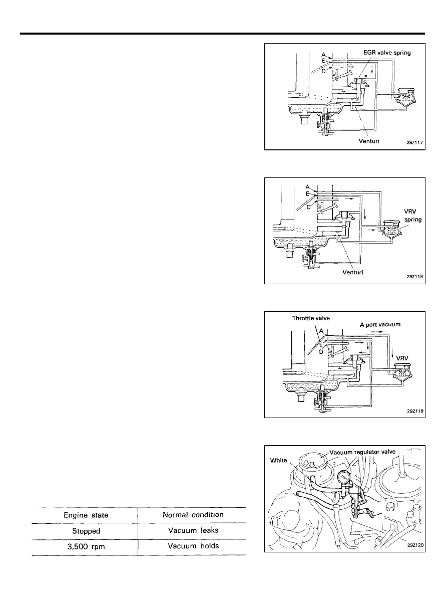
4. During Heavy Load Operation
During heavy load acceleration or other conditions in which
much NOx is produced. Ported vacuum acts on the VRV to
shut off E vacuum’s escape passage to atmosphere and to
stop EGR exhaust pressure control action.
As a result, the EGR valve is controlled by E vacuum and
the EGR flow rate increases.
Vacuum Regulator Valve (VRV) Inspection
1.
Disconnect the vacuum hose (white stripe) from the VRV and
connect a hand vacuum pump to the VRV.
2.
Apply a vacuum of 53 kPa (7.7 psi) and check VRV condition
as follows.
2 9 - 4 2
EXHAUST EMISSION CONTROL SYSTEM (FBC)
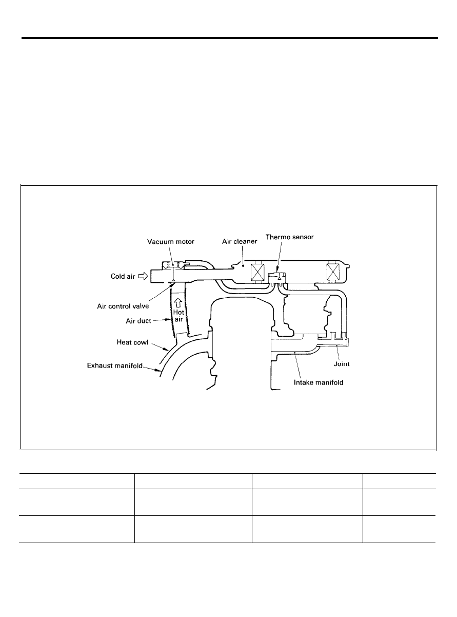
HEATED AIR INTAKE (HAI) SYSTEM
All vehicles are equipped with a temperature regulated air
cleaner, as shown in illustration. This allows the carburetor to
be calibrated leaner to reduce CO and HC emissions and
improved
engine
warm-up characteristics and minimized
carburetor icing. The air cleaner is provided with an air control
valve, inside the snorkel, to modulate temperature of carburetor
intake air which flows through two routes. The air control valve
is operated by a bimetal which responds to the temperature valve
combination system which responds to the intake manifold
vacuum and temperature inside the air cleaner.
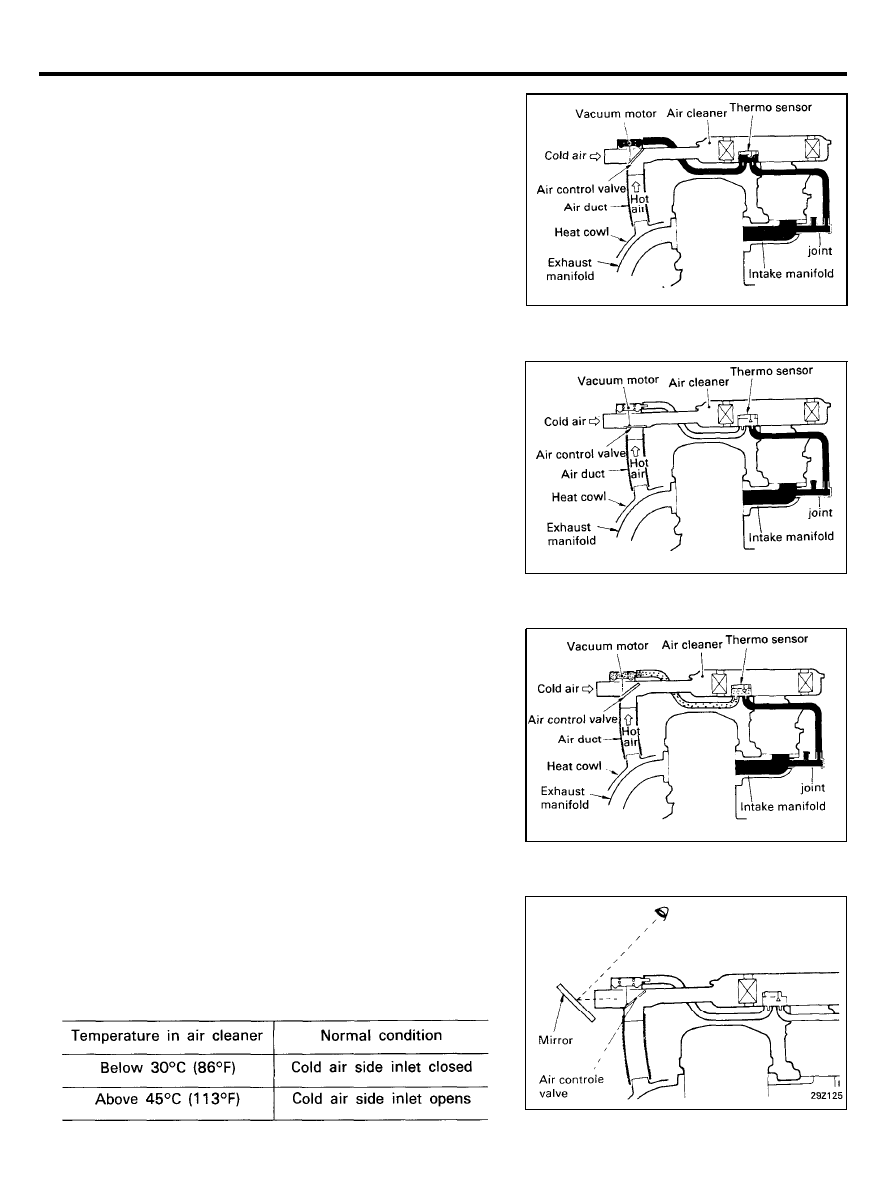
Temperature in air cleaner
Thermo valve
Air control valve
intake air
Atmospheric port is CLOSED
Heated air passage OPEN
HOT
Cold
Below 30°C (80°F)
Hot
Above 45°C (113°F)
Atmospheric port is OPEN
Cooled air passage OPEN
COOL
2 9 - 4 3
EXHAUST EMISSION CONTROL SYSTEM (FBC)
Operating Principle
1.
When the bimetal senses the temperature inside air cleaner
of below about 30°C (86°F) the air bleed valve of
temperature sensor remains closed.
Then, the intake manifold vacuum is applied to the
diaphragm of vacuum motor, which in turn, opens the air
control valve so as to let the pre-heated intake air flow
through the heat cowl and air duct into the air cleaner.
2.
When the bimetal senses the temperature inside air cleaner
of above 45°C (113°F) the air bleed valve is fully opened.
As a result, the intake air to the carburetor comes directly
through the fresh air duct, since the air control valve is
positioned as shown in illustration regardless of the intake
manifold vacuum.
3.
At intermediate temperatures, the air entering the carburetor
is a blend of fresh air and pre-heated air as regulated by the
thermostatically actuated air control valve.
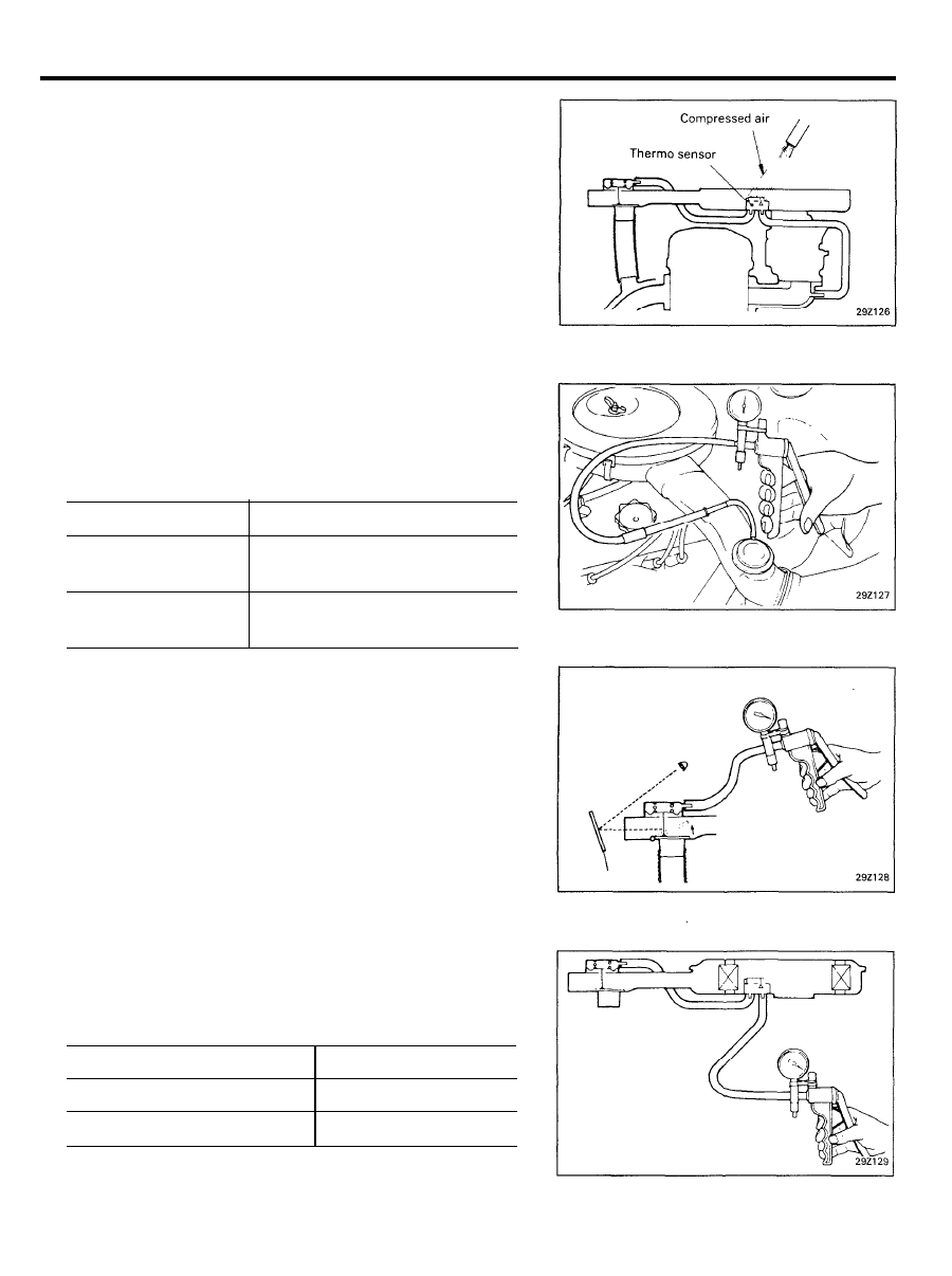
Inspection
1. HAI system
1) Remove the air cleaner cover and air duct.
2) Run the engine at idle and check air control valve
condition.
2 9 - 4 4
EXHAUST EMISSION CONTROL SYSTEM (FBC)
NOTE
If necessary, apply compressed air to cool or apply hot air
using a hair dryer, etc. to heat.
2. Air Control Valve
1) Remove the air cleaner.
2) Disconnect the vacuum hose from the air control valve
and connect a hand vacuum pump to the valve nipple.
3) Apply a vacuum and check air control valve operation.
Applied vacuum
Normal condition
Under 90 mmHg
(9.3 kPa, 1.4 psi)
Cold air side inlet fully opens
Over 190 mmHg
(25 kPa. 3.7 psi)
Cold air side inlet fully closed
4) Connect the disconnected vacuum hose to the original
position.
3. Thermo Valve
1)
Connect a hand vacuum pump to the thermo valve nipple
and apply vacuum.
2) Check the thermo valve operation.
Temperature in air cleaner
Normal condition
Below 30°C (86°F)
Vacuum holds
Above 45°C (113°F)
Vacuum leaks
2 9 - 4 5
EXHAUST EMISSION CONTROL SYSTEM (FBC)
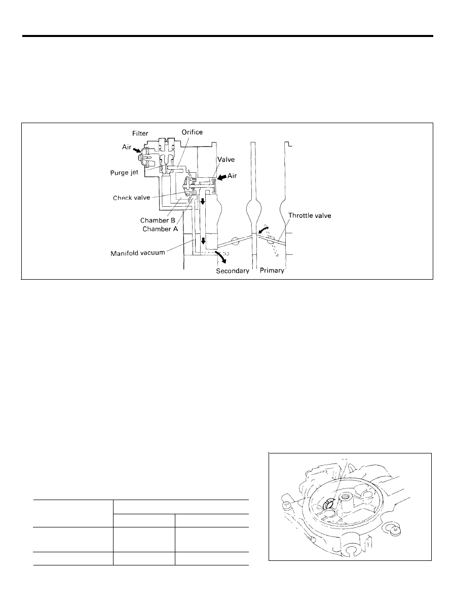
MIXTURE CONTROL VALVE (MCV)
When the throttle is closed suddenly during deceleration of
shifting, the fuel remaining in the intake manifold causes an
over-rich mixture temporarily.
In order to prevent this, air is supplied temporarily from another
passage to correct air-fuel ratio and reduce HC emission.
Operating Principle
When the throttle is closed suddenly, the manifold vacuum
increases sharply. This increased manifold vacuum acts on the
chamber A of the MCV to open the valve so that air is supplied
to the intake manifold. The vacuum is also supplied to chamber
B but with some delay due to an orifice. when the vacuum is
supplied to both chambers B and A, the spring causes the valve
to close, stopping supply of air. The check valve located at the
diaphragm prevents high vacuum from remaining the chamber
B during acceleration or deceleration. (If a high vacuum remains
in chamber B, the valve may fail to operate when vacuum acts
on chamber A).
Inspection
1. Remove the air cleaner.
2. After warming up the engine, open and close the throttle
valve quickly to check MCV valve operation and air suction
noise.
Engine condition
Normal condition
MCV valve
Air suction noise
Throttle lever
open and close
Open
Heard
Idling condition
Closed
Not heard
2 9 - 4 6
EXHAUST EMISSION CONTROL SYSTEM (FBC)
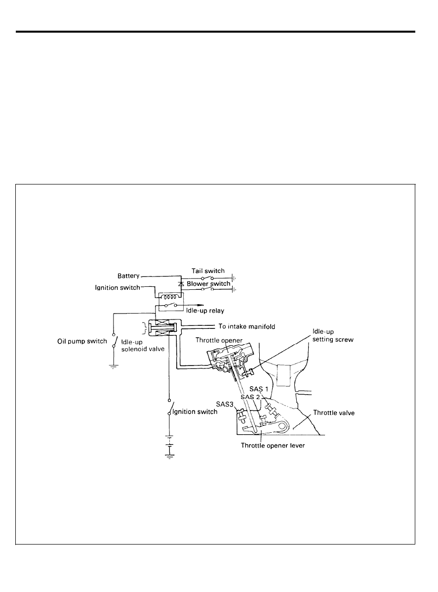
IDLE-UP SYSTEM
This system consists of a dash pot assembly, a solenoid valve,
a blower motor, a tail switch and the oil pump switch of the
power steering.
When the blower motor or the tail switch or oil pump switch
is turned on at the idle speed, the solenoid valve is opened. the
intake manifold vacuum acting on the dash pot opens the throttle
valve via the idle up lever which is freely movable on the throttle
valve shaft. Consequently, engine speed is increased whenever
power steering or electrical loads are high. when the above load
is turned off, the idle-up system stops working, and the engine
return to the original idle speed.
2 9 - 4 7
EXHAUST EMISSION CONTROL SYSTEM (FBC)
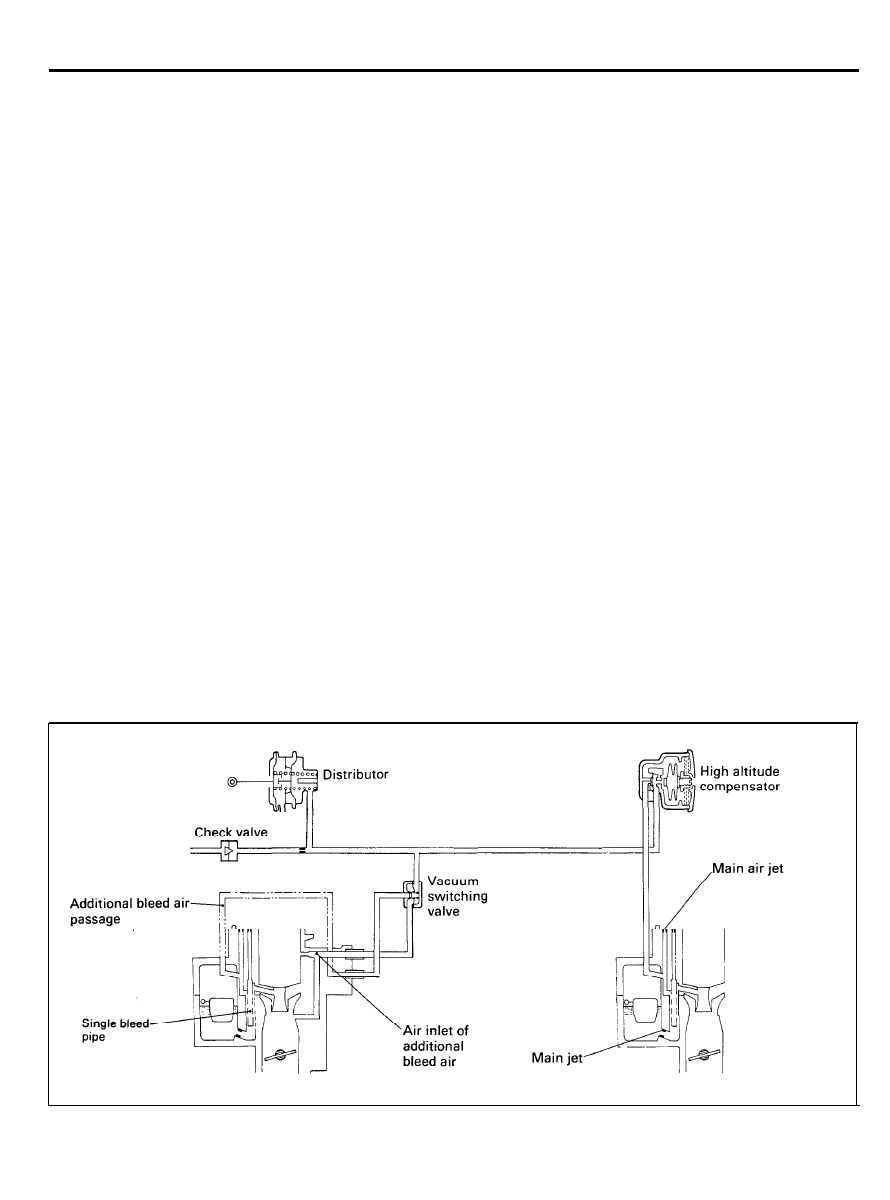
HIGH-ALTITUDE COMPENSATION SYSTEM
(FOR FEDERAL VEHICLES)
In order to meet the Federal requirements at all altitudes, all
carburetor vehicles are equipped with high altitude compen-
sation system in addition to feedback carburetor system. High
altitude compensation system consists of a high altitude
compensator (HAC), a vacuum switching valve and a distributor
equipped with high altitude advance system.
Air/fuel ratio at high altitude is controlled by the HAC to
approximately the same value as the one at sea level, by
supplying additional bleed air into the primary and secondary
main wells through HAC and vacuum switching valve controlled
by the HAC.
At low altitude, vacuum signal to a vacuum switching valve is
relieved to atmosphere via the HAC.
At high altitude, the HAC closes the air-leak line and a vacuum
signal is sent to the vacuum switching valve. The vacuum
switching valve opens and additional bleed air supplied to the
primary emission well.
At high altitude, the HAC also opens the additional air bleed
passage in the emission well.
The air/fuel ratio is’ precisely controlled by feedback carburetor
system to comply with the applicable emission standards at all
altitudes.
In order to reduce HC and CO emissions and to get better
driveability at high altitude ignition timing is advanced by
specified degrees at high altitude.
Spark advance vacuum signal is sent to the sub-diaphragm
chamber of the distributor via the HAC.
2 9 - 4 8
EXHAUST EMISSION CONTROL SYSTEM (FBC)
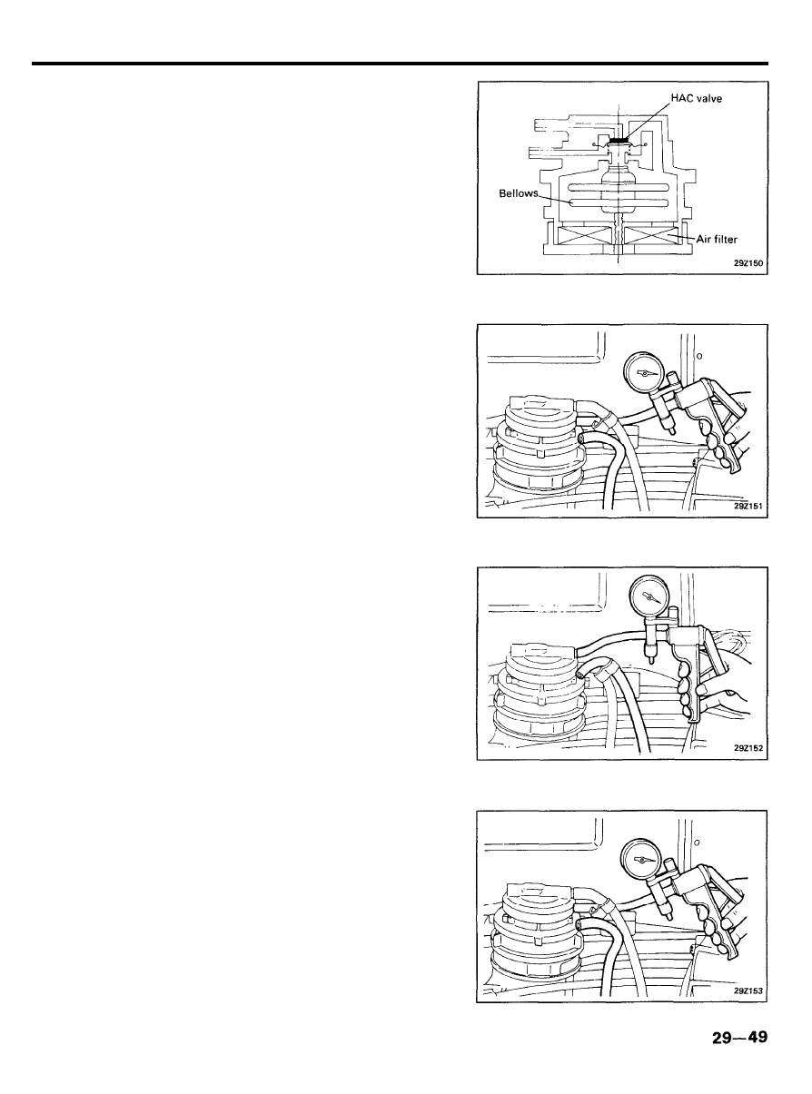
Inspection
1. HAC Valve (For Federal Vehicles)
(a) Remove the HAC and look for deformation or cracks.
(b) Clean the air filter in the HAC valve.
(c) At altitude below 1,200 m (3,900 ft)
o Disconnect the vacuum hose from the HAC and
connect a hand vacuum pump to the HAC lower
nipple.
o Apply vacuum and check that it leaks and does not
hold.
o Disconnect the vacuum hose from the HAC lower
nipple and connect a hand vacuum pump to the HAC
upper nipple.
o Check that vacuum holds when applied.
(d) At altitude above 1,200 m (3,900 ft)
o Disconnect the vacuum hose from the HAC and
connect a hand vacuum pump to the HAC lower or
upper nipple.
o Check that vacuum holds when applied.
Wyszukiwarka
Podobne podstrony:
10 Emission control system
10 Emission control system
96ZJ 25 EMISSION CONTROL SYSTEMS
10 Emission control system
Group 025 Emission Control Systems
93ZJ Secc 25 Emission Control Systems
Control System Toolbox
10 Engine Control System
6J Emissions Controls
wykład 07 zeszły rok systemy szkolne - Malta, studia, andragogika
ENGINE CONTROL SYSTEM
10 Engine Control System
Core Wall Survey Control System for High Rise Buildings
Air Control System
80 Vehicle Control System
Microprocessor Control System for PWM IGBT Inverter Feeding Three Phase Induction Motor
12 Emission Control
więcej podobnych podstron