
page -1-
© MCS Electronics, 1995-2006
© MCS Electronics , 1995-2006

page -2-
© MCS Electronics, 1995-2006

page -3-
© MCS Electronics, 1995-2006
Dear reader.
Thank you for your interest in BASCOM.
BASCOM was "invented" in 1995. It was intended for personal usage only. I
decided to make it public as I found no other tool that was so simple to use.
Since that time, a lot of options and extensions were added. Without the help
and patience of the many users, BASCOM would not be what it is today : "the
best and most affordable tool for fast proto typing".
We hope that BASCOM will contribute in making your work with
microprocessors Easy and enjoyable.
The MCS Electronics Team

page -4-
© MCS Electronics, 1995-2006
Table of Contents
INDEX
11
Keyword Reference
11
Installing BASCOM-8051
13
BASCOM IDE
19
RUNNING BASCOM-8051
19
BASCOM IDE
20
File New
21
File Open
21
File Close
22
File Save
22
File Save As...
22
File Print Preview
22
File Print
23
File Exit
23
Edit Undo
24
Edit Redo
24
Edit Copy
24
Edit Cut
24
Edit Paste
25
Edit Find
25
Edit Find Next
25
Edit Replace
26
Edit Goto
26
Edit Indent Block
27
Edit Unindent Block
27
Editor Keys
28
Program Compile
29
Program Syntax check
30
Program Show Result
30
Program Simulate
31
Program Send to chip
34
Tools Terminal Emulator
35
Tools LCD designer
36
Tools Graphic Converter
36
Tools LIB Manager
37
Tools Triscent Converter
39
Tools Export to RTF
39
Options Compiler Output
39
Options Compiler Communication
40
Options Compiler I2C
41
Options Compiler LCD
42
Options Compiler Misc
42
Options Communication
43
Options Environment
44
Options hardware simulator
47
Options Programmer
47

page -5-
© MCS Electronics, 1995-2006
Options Monitor
47
Options Printer
48
Window cascade
49
Window Tile
49
Window arrange icons
49
Window minimize all
49
Help About
49
Help Index
50
Help on help
50
Help Shop
50
Help Forum
51
Help Support
51
Help Credits
51
Language fundamentals
52
Language fundamentals
52
BASCOM Language Reference
59
BASCOM Statements
59
#IF
62
#ELSE
63
#ENDIF
64
1WIRE
65
1WIRECOUNT
66
1WSEARCHFIRST
68
1WSEARCHNEXT
69
$ASM - $END ASM
71
$BAUD
72
$BGF
72
$CRYSTAL
74
$DEFAULT XRAM
75
$EXTERNAL
75
$INCLUDE
76
$IRAMSTART
77
$LARGE
77
$LIB
78
$LCD
78
$LCDRS
79
$MAP
79
$NOBREAK
80
$NOINIT
81
$NONAN
81
$NONULL
82
$NORAMCLEAR
82
$NOSP
83
$OBJ
83
$RAMSIZE
84
$RAMTRON
84
$RAMSTART
86
$REGFILE
87
$ROMSTART
87

page -6-
© MCS Electronics, 1995-2006
$SERIALINPUT
88
$SERIALINPUT2LCD
89
$SERIALOUTPUT
89
$SIM
90
$TIMEOUT
90
$WAIT
91
ALIAS
91
ABS
92
ASC
93
AVG
94
BAUD
94
BCD
95
BITWAIT
95
BREAK
96
CALL
97
CHR
98
CLS
98
CONST
99
CONFIG
100
CONFIG 1WIRE
100
CONFIG ADUC812
101
CONFIG BAUD
102
CONFIG BAUD1
102
CONFIG DEBOUNCE
103
CONFIG I2CDELAY
103
CONFIG GETRC
104
CONFIG GRAPHLCD
104
CONFIG LCDPIN
108
CONFIG LCD
108
CONFIG LCDBUS
109
CONFIG MICROWIRE
110
CONFIG PRINT
111
CONFIG SCL
111
CONFIG SDA
112
CONFIG SERVOS
112
CONFIG SPI
113
CONFIG TIMER0, TIMER1
114
CONFIG WATCHDOG
115
COUNTER
116
CPEEK
117
CURSOR
118
DATA
118
DEBOUNCE
120
DECR
121
DECLARE
122
DEF
123
DEFLCDCHAR
123
DELAY
124
DIM
124

page -7-
© MCS Electronics, 1995-2006
DISABLE
125
DISPLAY
126
DO
127
ELSE
127
ENABLE
128
END
128
END IF
129
ERASE
130
EXIT
131
FOR
131
FOURTHLINE
132
FUSING
133
GET
134
GETAD
135
GETAD2051
136
GETRC
141
GETRC5
142
GOSUB
144
GOTO
144
HEX
145
HEXVAL
145
HIGH
146
HIGHW
147
HOME
147
I2CRECEIVE
148
I2CSEND
149
I2C
150
IDLE
151
IF
151
INCR
152
INKEY
153
INP
154
INPUT
155
INPUTBIN
156
INPUTHEX
157
INSTR
158
LCASE
159
LCD
160
LCDINIT
161
LCDHEX
163
LEFT
163
LEN
164
LOAD
164
LOCATE
165
LOOKUP
166
LOOKUPSTR
167
LOW
168
LOWW
168
LOWERLINE
169

page -8-
© MCS Electronics, 1995-2006
MAKEBCD
169
MAKEDEC
170
MAKEINT
170
MAX
171
MID
172
MIN
172
MOD
173
MWINIT
173
MWREAD
174
MWWOPCODE
175
MWWRITE
176
NEXT
176
ON interrupt
177
ON value
178
OPEN
179
OUT
181
PORT
182
PEEK
182
POKE
183
POWERDOWN
183
184
PRINTBIN
185
PRINTHEX
186
PRIORITY
186
PSET
187
PUT
188
READ
189
READMAGCARD
190
REM
191
REPLACE
192
RESET
192
RESTORE
193
RETURN
194
RIGHT
194
RND
195
ROTATE
196
SELECT
196
SET
197
SHIFTCURSOR
198
SHIFT
198
SHIFTIN
199
SHIFTLCD
200
SHOWPIC
201
SOUND
201
SPACE
202
SPC
203
SPIIN
203
SPIINIT
204
SPIOUT
205

page -9-
© MCS Electronics, 1995-2006
START
205
STOP
206
STOP Timer
206
STR
208
STRING
208
SUB
209
SWAP
210
THIRDLINE
210
UCASE
211
UPPERLINE
212
VAL
212
VARPTR
213
WAIT
213
WAITKEY
214
WAITMS
214
WATCHDOG
215
WHILE .. WEND
216
Using assembly
217
Using assemly
217
Internal registers
224
Initialization
226
Additional Hardware
227
Additional Hardware
227
Alternative port-pin functions
232
Hardware - LCD display
233
Hardware - I2C
234
1WIRE INFO
234
Supported Programmers
238
MCS Flash programmer
238
MCS SPI programmer
240
Blow IT Flashprogrammer
241
PG2051 flash programmer
241
PG302 programmer
242
SE512 or SE514 programmer
243
SE-812
243
Sample Electronics ISP programmer
244
CYGNAL JTAG Programmer
246
Futurelec
246
JPK Systems X-programmer
246
Peter Averill's TAFE programmer
247
STK200/300 ISP Programmer
248
Rhombus SCE-51
250
SE511-SE516 programmer
251
BASCOM Misc
253
Error messages
253
Compiler Limits
256
Reserved Words
257
Microprocessor support
261
Microprocessor support
261

page -10-
© MCS Electronics, 1995-2006
TIMER2
262
DATA EEPROM
265
AT898252 WATCHDOG
265
WATCHDOG 80515
266
INTERRUPTS and PRIORITY 80515
266
INTERRUPTS and PRIORITY 80537
267
ADUC 812
268
89C51
270
International Resellers
272
International Resellers
272
Third party hardware
273
Third party Hardware
273
Grifo
273
Rhombus
281

page -11-
© MCS Electronics, 1995-2006
BASCOM-8051
© 1995-2006 MCS Electronics
Help Version 2.0.13.0
See
for the installation procedure
MCS Electronics may update this documentation without notice.
Products specification and usage may change accordingly.
MCS Electronics will not be liable for any miss-information or errors found in this document.
All software provided with this product package is provided 'AS IS' without any warranty
expressed or implied.
MCS Electronics will not be liable for any damages, costs or loss of profits arising from the
usage of this product package.
No part of this document may be reproduced or transmitted in any form or by any means,
electronic or mechanical, including photocopying and recording, for any purpose, without
written permission of MCS Electronics.
Copyright MCS Electronics. All rights reserved.
Keyword Reference
1WIRE
1Wire routines allow you to communicate with Dallas 1wire chips.
1WRESET, 1WREAD, 1WWRITE
,
1WSEARCHFIRST
,
1WSEARCHNEXT
,
1WIRECOUNT

page -12-
© MCS Electronics, 1995-2006
Conditions
Conditions execute a part of the program depending on the condition
Configuration
Configuration command initialize the hardware to the desired state.
Conversion
A conversion routine is a function that converts a number or string.
,
Delay
Delay routines delay the program for the specified time.
Directives
Directives are special instructions for the compiler. They can override a setting from the IDE.
Graphical LCD
Graphical LCD commands extend the normal text LCD commands.
I2C
I2C commands allow you to communicate with I2C chips with the TWI hardware or with
emulated I2C hardware.
I2CRECEIVE
,
I2CSEND
,
I2CSTART
,
I2CSTOP
,
I2CRBYTE
,
I2CWBYTE
Interrups
Interrupt related routines.
ON Interrupt
,
ENABLE
,
DISABLE
,
PRIORITY
IO
I/O commands are related to the I/O pins of the processor.
ALIAS
,
BITWAIT
,
DEBOUNCE
,
SET
,
RESET
Math
Math functions
ABS
,
AVG
,
MAX
,
MIN
,
MOD

page -13-
© MCS Electronics, 1995-2006
Micro
Micro statements are highly related to the micro processor.
Memory
Memory functions set or read RAM , EEPROM or flash memory.
Remote control
Remote control statements send or receive IR commands for remote control.
RS-232
RS-232 are serial routines that use the UART or emulate a UART.
SPI
SPI routines communicate according to the SPI protocol with either hardware SPI or software
emulated SPI.
String
String routines are used to manipulate strings.
Text LCD
Text LCD routines work with the normal text based LCD displays.
CLS
,
CURSOR
,
FOURTHLINE
,
HOME
,
LCD
,
LCDINIT
,
LCDHEX
,
LOCATE
,
SHIFTLCD
,
Various
This section contains all statements that were hard to put into another group
CALL
,
CONST
,
COUNTER
,
DECR
,
DECLARE
,
DEFINT
,
DEFBIT
,
DEFBYTE
,
DEFLCDCHAR
,
,
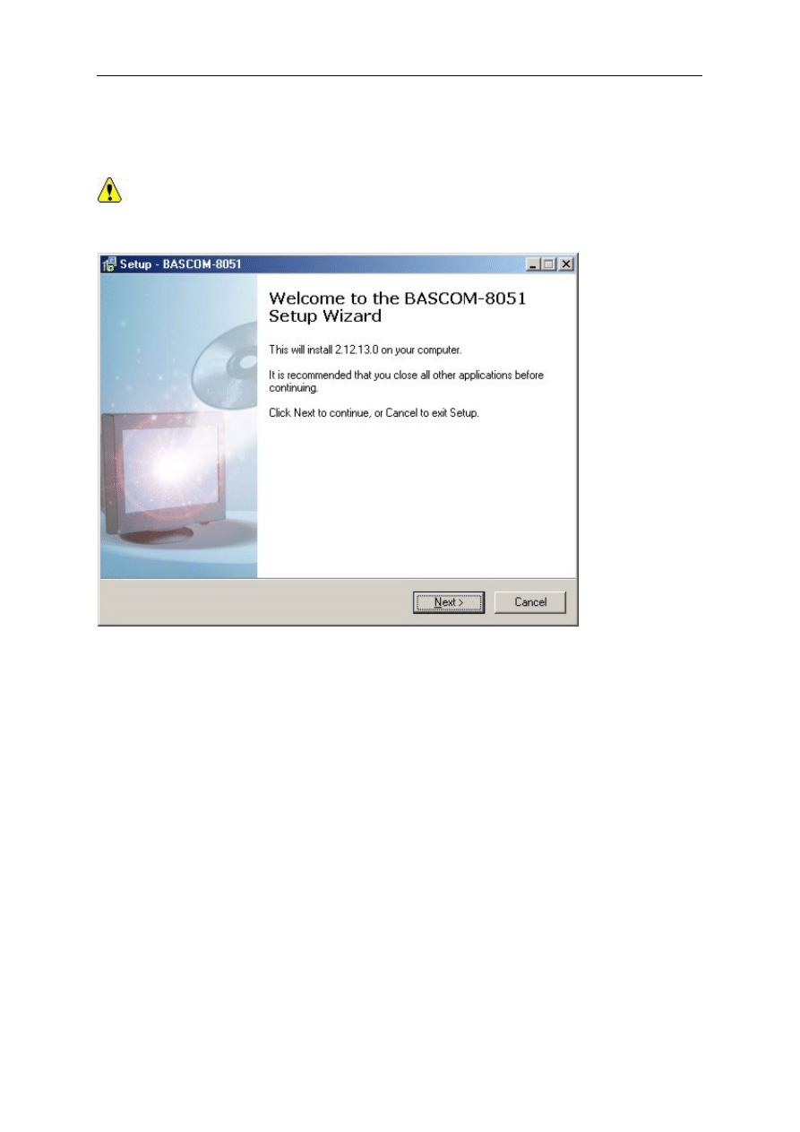
Installing BASCOM-8051
After you have downloaded the software you need to UNZIP the downloaded file.
page -14-
© MCS Electronics, 1995-2006
There is only one file named setup.exe
You may run this setup.exe from within the Windows Shell but it is important to notice that
when you use the commercial version, you MUST UNZIP the setup.exe since you need to copy
the license file to the same directory as setup.exe.
You must have Administrator rights in order to be able to run setup.
The opening screen looks like :
You need to click the Next-button to continue.
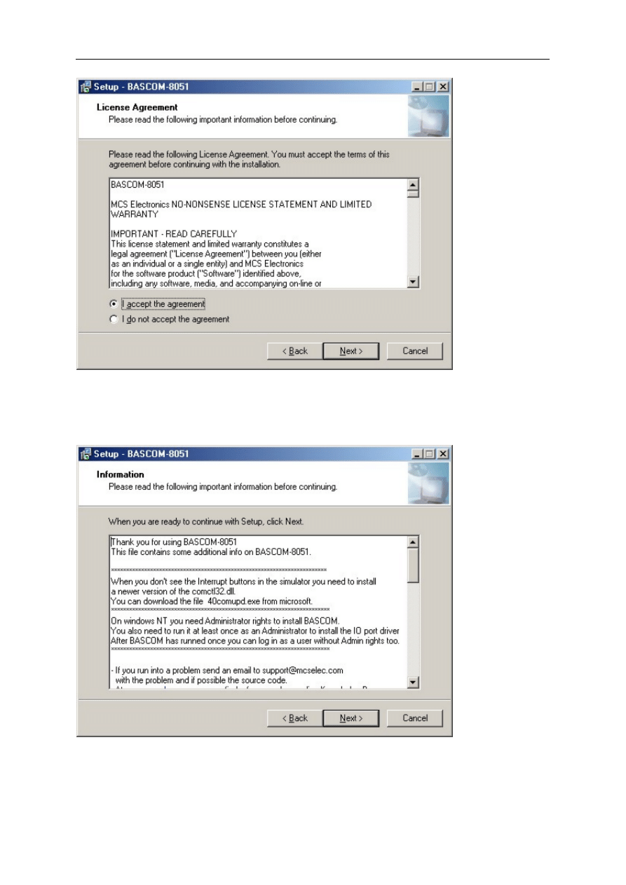
A license agreement will be shown. You need to read it and accept the agreement.
This is a no-nonsense agreement where you are allowed to install/copy on as many
computers as you want, providing that you use only one computer at the same time.
page -15-
© MCS Electronics, 1995-2006
After clicking the 'I accept the agreeement' option, you need to click the Next-button again to
continue.
The readme.txt file is shown. Basicly it tells you to contact support@mcselec.com in case of a
problem.
Click the Next-button again to continue with the setup.
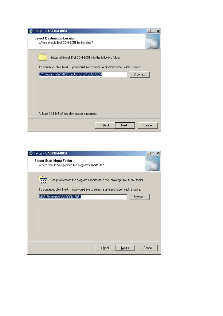
You can now select where you want to Install BASCOM-8051.
The default is shown below.
page -16-
© MCS Electronics, 1995-2006
Click the Next-button again to continue.
You can now select/enter the Program Group name. The default is shown below.
Click the Next-button again to continue.
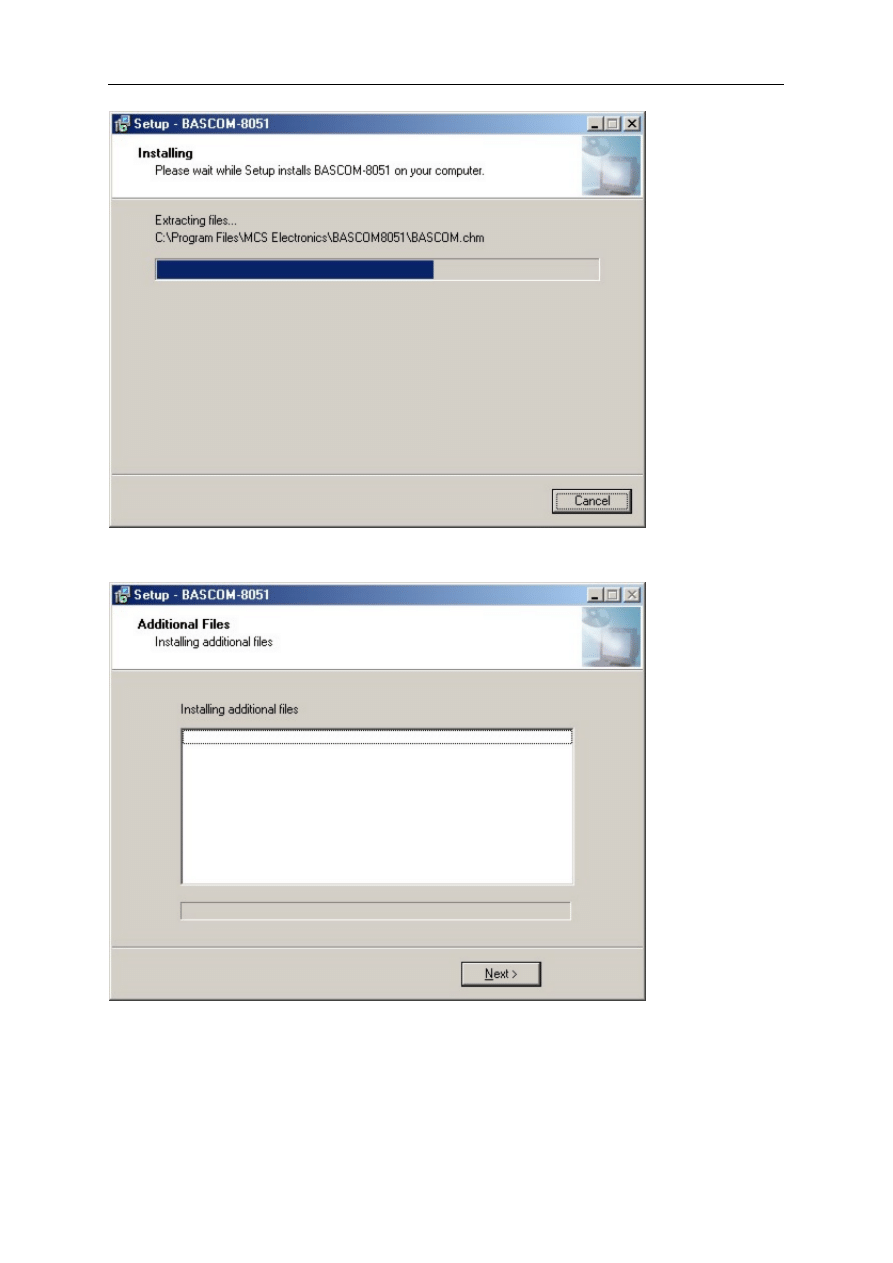
The files will now be installed.
A screenshot is shown below :
page -17-
© MCS Electronics, 1995-2006
When the files are installed, the installer will install some addiitonal files :
Press the Next-Button to install the additional files. This will go quick in most cases. When
you install from CD-ROM the setup will also copy PDF datasheets. The installation will take
longer then.
When setup is completely finished it will show the last screen :
page -18-
© MCS Electronics, 1995-2006
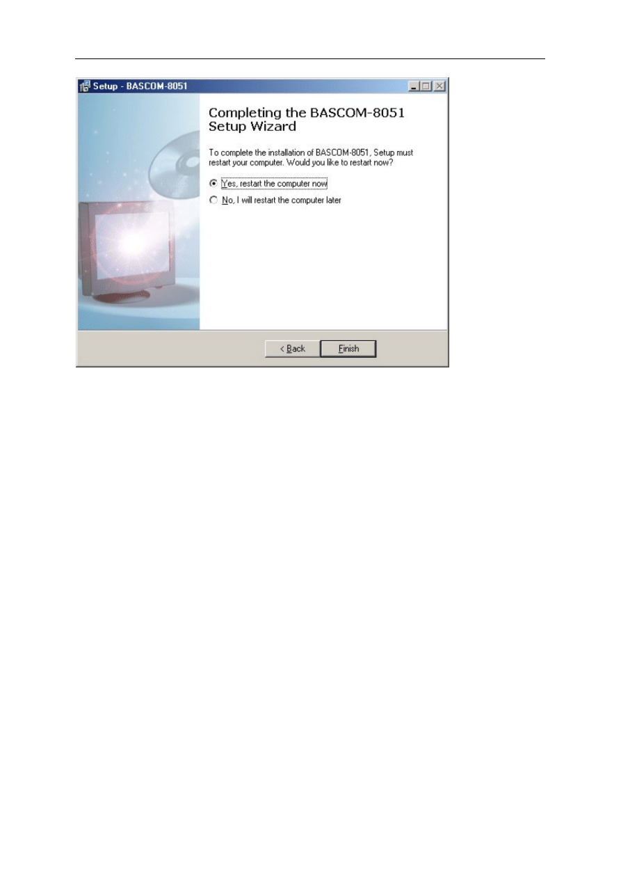
You MUST reboot your PC since it will install a driver needed for the programming.
page -19-
© MCS Electronics, 1995-2006
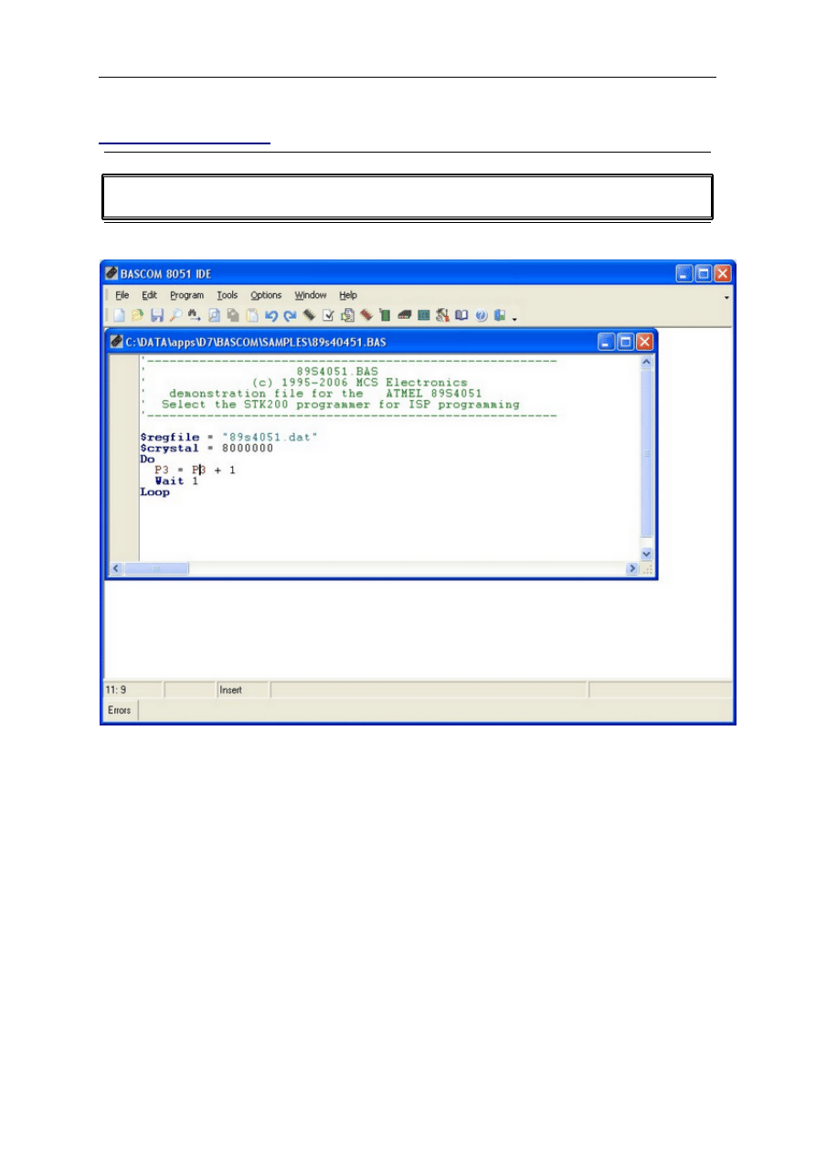
BASCOM IDE
RUNNING BASCOM-8051
When you run BASCOM-8051 the following window will appear.
The last saved/closed program will be loaded automatic.
When reformatting is enabled, the loaded program will be reformatted too.
This is only meaningful for programs written with another editor.
The BASCOM IDE is a so-called multi document application. This means that you can open
more than one source file. The operations that you perform are always done on the current
document, that is, the window with the focus.
The filename is shown in the caption of the window.
The status bar is separated in four panels.
o
line, character position indicator
o
modified indicator, to indicate that text has changed
o
insert/overwrite indicator
o
message panel
Some actions will make a progress indicator visible.

page -20-
© MCS Electronics, 1995-2006
BASCOM-8051 IDE
File
Edit
Edit Paste
Edit Find Next
Program
Compile
Syntax check
Simulate
Send to chip
Tools
Terminal Emulator
Options

page -21-
© MCS Electronics, 1995-2006
Window
Help
Shop
File New
Action
This option creates a new window in which you can write your program.
The focus is set to the new window. Depending on the environment settings, the window is
normal sized or maximized.
Note that you must save your program before you can compile it. Newly created files will
have the name [nonameX] in the window caption. Where X is a number starting with 1 for
the first editor window.
Before you can compile your program, you must give it a valid name.
File Open
Action
With this option, you can load an existing program from disk.
BASCOM saves files in ASCII format. Therefore, if you want to load a file, which is made with
another editor, be sure that it is saved as an ASCII file.

page -22-
© MCS Electronics, 1995-2006
You can specify that BASCOM must reformat the file when it opens the file.
See
This should only be necessary when loading files made with another editor.
Since saved/closed files are put in a so called 'recent file list' , you can also open a file by
selecting it from the File menu.
File Close
Action
Close current editor window. When changes are made, and they are not saved yet, you will
be asked to save your program.
File Save
Action
With this option, you can quick save your current program to disk.
If the program was created with the
option, you will be asked for a filename first.
Use the
option to save the file with another name.
Note that the file is saved as an ASCII file.
File Save As...
Action
With this option, you can save your current program to disk.
You can enter a filename before your program is saved.
Note that the file is saved as an ASCII file.
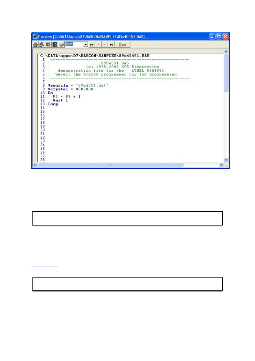
File Print Preview
Action
This will display the print preview window.
page -23-
© MCS Electronics, 1995-2006
By clicking the Setup-button, you can change some printer properties. For margin settings,
you must use the
. For a hardcopy, click the Print-button.
See also
File Print
Action
With this option, you can print the current program.
Note that the current program is the editor window, which has the focus.
See also
Print preview
File Exit
Action
With this option, you can leave BASCOM.
If you have made changes to your program, you can save them upon leaving BASCOM.

page -24-
© MCS Electronics, 1995-2006
Edit Undo
Action
With this option you can undo the last change you made to your program.
By selecting this option again, you can undo the previous change to your program.
See also
Edit Redo
Action
With this option you can redo the last undo action.
See also
Edit Copy
Action
With this option, you can copy selected text into the clipboard. You can select text by
dragging the mouse cursor over the text or by Double clicking on a word.
Another possibility is to hold the shift key down and pressing the cursor keys. Selected text is
shown inverted.
Shortcut
CTRL+C and CTRL+INS
Edit Cut
Action
With this option, you c an cut selected text into the clipboard.
The selected text is copied into the c lipboard, and deleted from your program.
Shortcut
CTRL+T
Edit Paste
page -25-
© MCS Electronics, 1995-2006
Action
With this option, you can paste text from the clipboard into the current cursor position.
Shortcut
CTRL+ V and SHIFT + INS
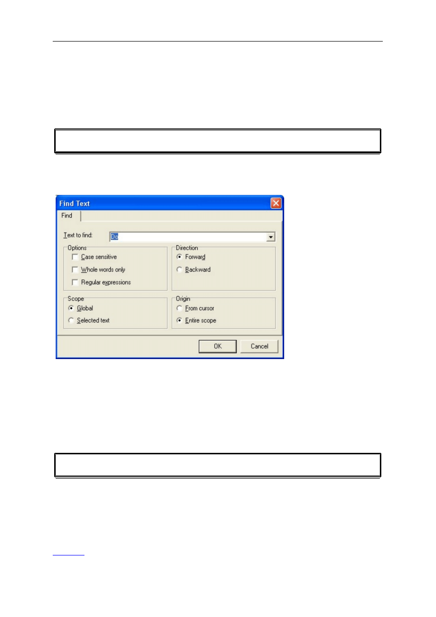
Edit Find
Action
With this option, you c an search for text in your program. The following dialog window will
appear:
You can choose to seach forward or backward. Optional you can seach case sensitive and for
whole words.
Regular expressions are also supported.
Shortcut
CTRL+F
Edit Find Next
Action
With this option you can search for the next occurrence of the specified text.
When you didn't specify a search text, you will be asked for the text to find, with the windows
find-dialog.
See Also
Edit Find
page -26-
© MCS Electronics, 1995-2006
Shortcut
F3
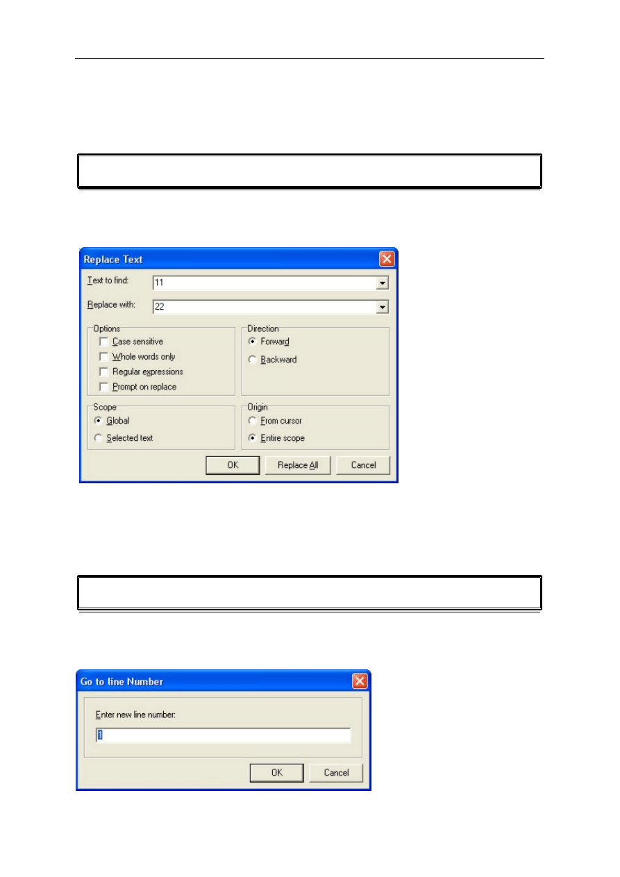
Edit Replace
Action
With this option, you can replace text in your program.
The following replace dialog will appear:
Enter the text to search for and the text to replace with, and press return.
Shortcut
CTRL+R
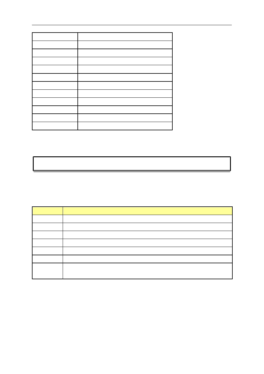
Edit Goto
Action
With this option you can type the line number of the line you want to go to.
The following screen will be shown :

page -27-
© MCS Electronics, 1995-2006
The current line number will be shown. You can edit this and press RETURN to jump to the
line number of your choice.
Edit Ident Block
Action
Indents a block of selected text.
You need to select at least one line in order to use this option.
When you have a structure like :
Do
a=a+1
b=b+1
Loop
It is hard to see the structure. You can best indent your code.
Do
a=a+1
b=b+1
Loop
When you have code that is not indented you can indent it by selecting the two line within
the structure and choose 'Edit Indent Block'.
Edit Unindent Block
Action
UnIndents a block of selected text.
You need to select at least one line in order to use this option.
When you have a structure like :
Do
a=a+1
b=b+1
Loop
It is hard to see the structure. You can best indent your code.
Do
a=a+1
b=b+1
Loop
When you have code that is not indented you can indent it by selecting the two line within
the structure and choose 'Edit Indent Block'. The Unindent option can be used when the code
is too much indented :

page -28-
© MCS Electronics, 1995-2006
Do
a=a+1
b=b+1
Loop
The sample above show that too much idention does not make the program readable.
Editor Keys
The following table lists all editor shortcuts.
Key
Action
LEFT ARROW
One character to the left
RIGHT ARROW
One character to the right
UP ARROW
One line up
DOWN ARROW
One line down
HOME
To the beginning of the line
END
To the end of the line
PAGE UP
Up one window
PAGE DOWN
Down one window
CTRL+LEFT
One word to the left
CTRL+RIGHT
One word to the right
CTRL+HOME
To the start of the text
CTRL+END
To the end of the text
CTRL+ Y
Delete current line
INS
Toggles insert/overstrike mode
F1
Help (context sensitive)
F2
File Simulation
F3
Find next text
F4
Send program to chip or run programmer
F5
Run program (simulator)
F7
Compile File
CTRL+F7
Syntax check
F8
Step through program (simulator)
SHIFT + F8
Step over code (simulator)
F9
Toggle breakpoint (simulator)
F10
Run to cursor (simulator)
CTRL+J
Pop up code template
CTRL+G
Goto line
CTRL+O
Load File
CTRL+S
Save File
page -29-
© MCS Electronics, 1995-2006
CTRL+P
Print File
CTRL+T
Terminal emulator
CTRL+F
Find text
CTRL+W
Show result of compilation
CTRL+L
LCD designer
CTRL+X
Cut selected text into clipboard
CTRL+C
Copy selected text into clipboard
CTRL+V
Copy text from clipboard into editor
CTRL+Z
Undo
CTRL+SHIFT+Z
Redo
CTRL+SHIFT+I
Indent block
CTRL+SHIFT+U
Unindent block
To select text: Hold the SHIFT key down and use the cursor keys to select text. or keep the
left mouse key pressed and tag the cursor over the text to select.
To select a word, double click on it.
Program Compile
Action
With this option you c an compile your current program. Your program will be saved
automatically before it will be c ompiled.
So if you didn't give it a nam e, you will be asked for it.
The following files will be created depending on the
Option Compiler Settings.
File
Description
xxx.BIN
Binary file which can be burned into EPROM.
xxx.DBG
Debug file which is needed by the simulator.
xxx.HEX
Intel hexadecimal file.
xxx.ERR
Error file. (only when errors are found)
xxx.RPT
Report file.
xxx.SIM
xxx.PRJ
Generated by the simulator to store the variable names of the watch window
and the breakpoints.
If an error occurs, you will receive an error message and the compilation will end.
The cursor will be set to the line in which the error occurred. The line will be marked with a
red color too. The red marking color will disappear when you compile the program again.
Shortcut
F7
page -30-
© MCS Electronics, 1995-2006
Program Syntax check
Action
With this option you can check the syntax of your program.
No files are generated with this option.
Shortcut
CTRL+F7
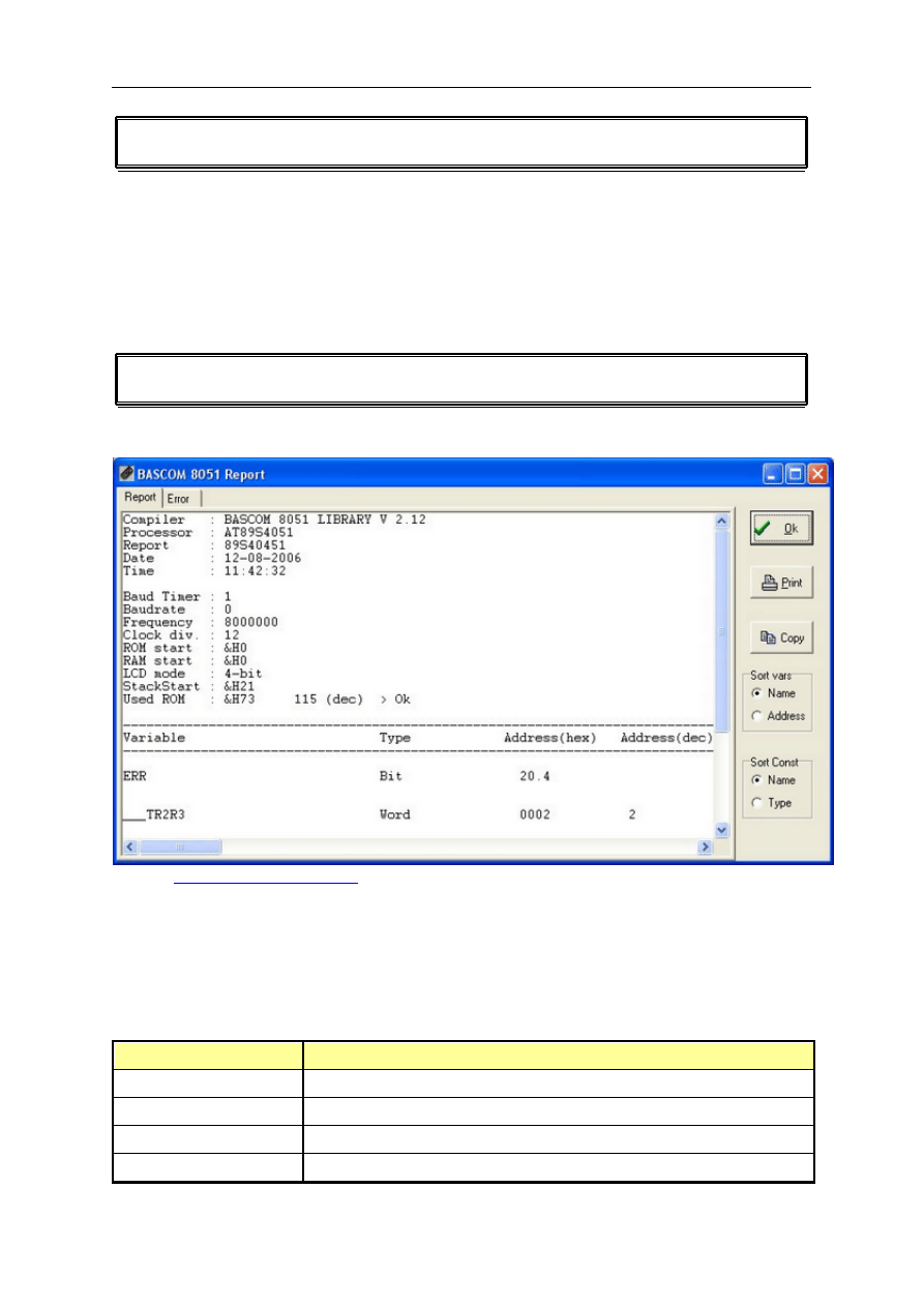
Program Show Result
Action
Use this option to view the result of the compilation.
See the
Options Compiler Output
for specifying which files must be created.
The files that can be viewed are report and error.
Click the Print button to print the selected file.
Click the Ok button to return to the editor.
Shortcut
or CTRL+W
Information provided in the report:
Info
Description
Compiler
Shows the version of the library (the compiler).
Processor
The type of microprocessor the file is compiled for.
Report
The name of the source file.
Date and time
The compilation date and time.
page -31-
© MCS Electronics, 1995-2006
Comp.time
The start and end time needed for compilation.
Baud timer
The timer used for the generation of the baud rate.
Baudrate and frequency The baud rate selected for the uP and the used crystal. This info is
used for RS232 related statements such as PRINT and INPUT. Note
that when you use the $crystal and $baud statements the exact
baud rate is shown.
ROM start
The starting location of ROM memory.
RAM start
The starting location of RAM memory.
LCD mode
4 bit or 8 bit LCD mode.
Stack start
The starting location of the stack. The space below the stack is used
for internal variables. The stack grows when calls are made by the
machine language routines.
Used ROM
Displays the length of the binary file.
Variable
The name, type and the location in memory of the used variables
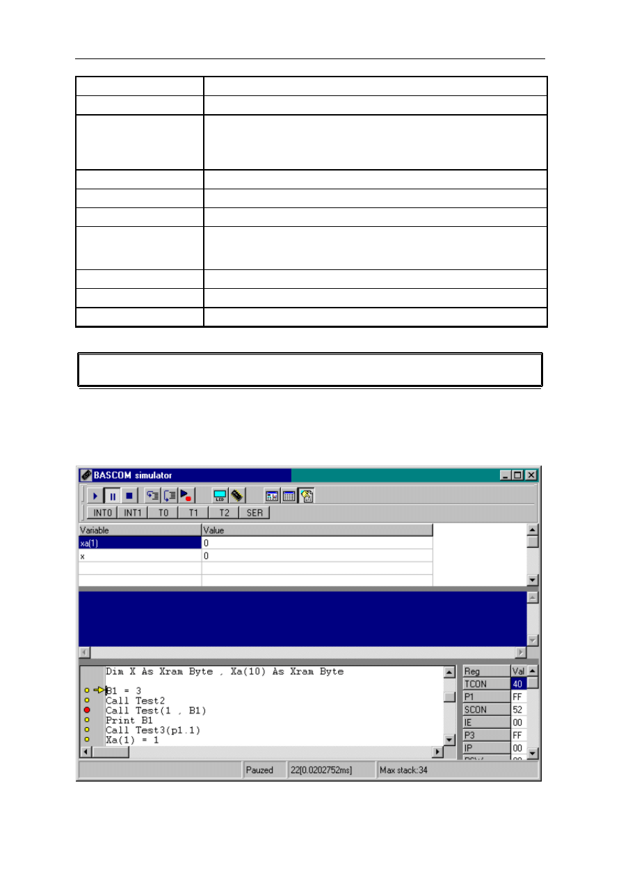
File Simulate
This option displays the Simulator window in which you can simulate a c ompiled program.
When the source c ode is saved without c ompiling, you will be warned that the debug file
differs from the source code. You have the option to com pile it before you simulate or
c ontinue without rec ompiling.
The simulator window is divided in a few sections.

page -32-
© MCS Electronics, 1995-2006
Toolbar with speed buttons
Variable watch/modify window
Source code window
Terminal (input/output) window
Register window
Status bar
The margin
On the left side a margin is visible. This margin can display the following ic ons:
a yellow dot, indic ating that the line holds exec utable code
a read dot, indic ating that a break line is set. You c an only set a breakpoint on a line
that has a
yellow dot.
a yellow arrow. This arrow shows the line currently exec uting.
The register window
On the right side the register window is visible. You can change the value of a register by
entering a new value.
The variable watch section
The sec tion below the toolbar is the variable watc h section.
You can add a variable by entering one in an em pty c ell. You can also add a new variable by
selecting it from the source window, and pressing return.
You can insert a new variable watch line by pressing the INS-key.
You can delete a variable watc h line by pressing the CTRL+DEL keys.
You can c hange the value of a variable by setting the foc us to the c ell with the variables
value and then by entering the new value.
The variable names are saved and loaded after each sim ulation session.
The terminal section
The blue window emulates the serial port. So serial output (the PRINT statement for
example), is displayed in this window.
When serial input is required, you must set the focus to the serial window, before you enter
text. The INPUT statement for example, requires serial input.
The source code window
The source code windows shows the sourc e file being simulated.
You can start a sim ulation by pressing F5 or by c licking the run button .
When your program runs, you can pause it by clicking the pause button .
You can stop the sim ulation by clicking the stop button.
You can also step through the code line by line, by pressing F8, or by clicking the step
button
.
By pressing SHIFT+F8
, you can step over code, like GOSUB and CALL.
To pause execution at a certain line, you can set a breakpoint. Just set the cursor on that line
and press F9. By pressing F9 again, you can remove the breakpoint.
Note that a breakpoint can only be set on a line that contains executable code.
This is visible by the yellow dot. Statements like $romstart don't contain executable code and
won't have a corresponding yellow dot.
You can also run to a specified line by clicking the run to button
.
The statusbar
The status bar is also divided into a few sections. These sections from left to right display the
following information:
page -33-
© MCS Electronics, 1995-2006
The value of a variable in the sourc e code window. You c an select a variable by moving
the mouse cursor over the variable name.
The status of the sim ulator (stopped, running or paused)
The number of clock cyc les and the exec ution time of the exec uted code. You c an
reset the value by c licking on this section.
The stack depth of the program . The stack depth is the deepest level the stac k has
reached during execution. If it exc eeds the available internal memory (128 or 256 bytes),
the program will not run correctly in the chip.
The interrupt buttons
The INT0, INT1, T0, T1 and SER buttons can be clicked to generate an interrupt.
Because this is a software emulator, no hardware interrupts can be generated. You have to
do this yourself by clicking these buttons. TIMER 0 and TIMER 1 are simulated by software.
Therefore, they will generate an interrupt automatically if the software enables this. The
external gate however isn't simulated so for this occasion you must click the corresponding
button.
Depending on the chip used, other interrupt buttons can be visible. They have the same
purpose as the default interrupt buttons.
Hardware simulator button
By clicking the hardware simulator button
a special window will become visible. This
window has a LCD simulator, which can simulate custom characters, LED simulation for port
0-3, and a 7-digit LED display simulation.
The LCD type can be selected from the menu. Note that the display isn't as fast as it could
be, but to assign/display all the dots costs a lot of processor time. The advantage however is
that custom characters can be displayed too.
The LED's can be switched on or off by clicking on it.
The LED type can be set with the CG checkboxes. To select common ground you must set the
marker. This will have the effect that all common cathodes are connected to ground and so
the LED will be on when the port value will be high.
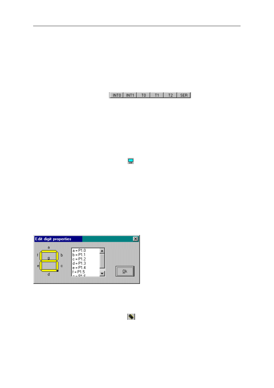
The 7-digit display can be connected to individual port pins.
To change the setting you must press the right mouse button to bring up the digit properties
window.
Each segment is named with a letter. To change a port pin, select the segment from the list
and press the spacebar. Now you can enter the desired port pin.
After you are done with assigning/changing, press the Ok button.
Real hardware simulation
Press the real hardware simulation button
to enable the hardware simulation.
You need additional hardware to use this feature. You c an use the MCS flash programmer to
simulate one port.
An application note can be downloaded that desc ribes the needed hardware.
The hardware simulator can simulate port 1 and 3.
This way you c an test your program in circuit without programming the device.
Now only the status reading and setting of the ports is supported.
© MCS Electronics, 1995-2006
This means that interrupts are not yet supported in hardware sim ulation.
Update source
The displaying of the variables and the arrow c osts a lot of proc essor time. To simulate faster,
you can disable the update of these item s. Click the button to enable/disable the update.
Display memory window
To display the memory of the internal RAM, you can click the button. By clic king again,
you can hide the window.
Refresh variables
Normally, variables are only refreshed in step m ode (F8), bec ause depending on the used
statements, the value would be hard to watch. You can also choose to display the value
during program execution. The default is on.
The sec tions can be made larger or smaller by using the splitters.
When you press the right mouse button, a popup m enu will be visible.
Depending on the place the m ouse cursor was at the tim e you pressed the right- mouse
button, different options will be showed.
Extra options that will be c ome available are:
Clear breakpoints
Hide register window
Hide watch window
To end a session c lose the windows or just set the foc us to an editor window.
Send to chip
After you have tested your program you can run one of the supported program mers. You c an
also press F4 or click on the
button.
Some programmers support the auto flash option from the programmers options.
When you select this option, the program mer window will not be visible, but the c hip will be
erased, programmed and verified automatically. The progress will be visible in the IDE-menu
bar.
Different serial comport and parallel printer port based programmers are supported. You
must select one first with the
Options Programmers
menu.
MCS Flashprogrammer
Blow IT Flashprogrammer
PG2051
MCS SPI programmer
PG302
JPK Systems X-programmer
Peter Averill's TAFE programmer
SE512 or SE514
SE-812
STK200/STK300 ISP programmer
Sample Electronics simple cable ISP programmer
page -35-
© MCS Electronics, 1995-2006
RHOMBUS SCE-51 Emulator
CYGNAL JTAG programmer
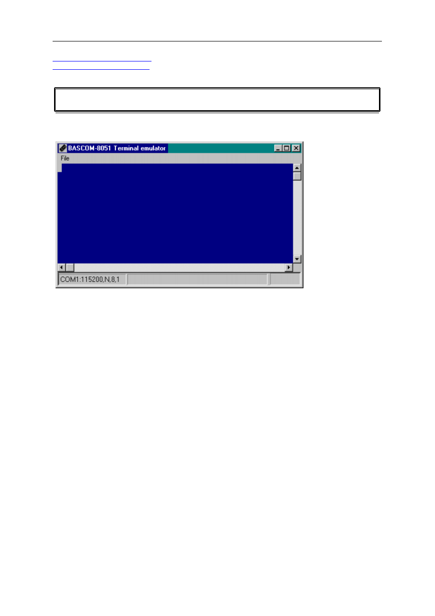
Tools Terminal Emulator
With this option you can start the built in terminal emulator.
The following window will appear:
The terminal emulator supports ANSI, TTY, VT100 and VT220 terminal emulation.
Information you type and information that the computer board sends,
are displayed in the same window.
You must use the same baud rate for the terminal emulator and the program you compile. If
you compiled your program with the Compiler Settings at 4800 baud, you must set the
Communication Settings also to 4800 baud. The setting for the baud rate is reported in the
report file.
The terminal menu has a few options.
File upload
This will upload the current program in HEX format to a monitor program.
With the Options Monitor settings, you can specify an optional header to be sent before the
actual hex file is sent to the monitor.
Also a delay in mS can be specified for a optional delays after each line sent.
When an ALTAIR ROM is selected from the Monitor Options, a binary file will be sent to the
monitor. The baud rate of the terminal emulator will be used.
For an 552 ALTAIR ROM, the terminal baud rate must be set to 115200 baud.
While sending the hex file to the monitor, an extra menu option will be available:
File Escape
This will abort the upload to the monitor program.
File Exit
This will close the terminal emulator window.
page -36-
© MCS Electronics, 1995-2006
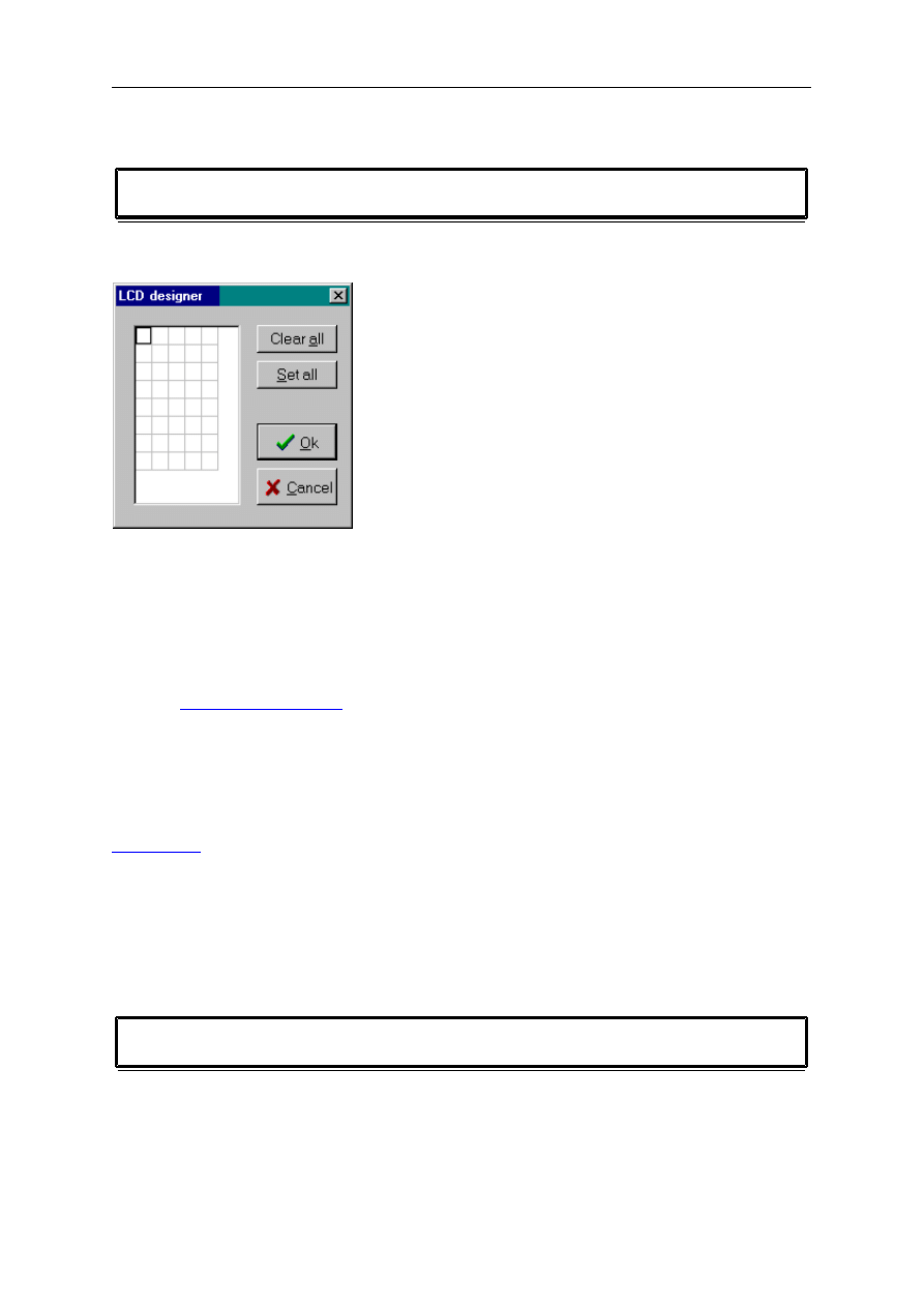
Tools LCD designer
With this option, you can design special characters for LCD displays.
The following window will appear:
The LCD matrix has 7x5 points.
The bottom row is reserved for the cursor but can be used.
You can select a point by clicking the left mouse button.
If a cell was selected it will be deselected.
By clicking, the Clear All button you can clear all points.
By clicking the Set All button you can set all points.
With the
settings you can choose if the 3 most significant bits must be
set high. Some LCD displays require this.
When you are finished you can press the Ok button:
a statement will be inserted in your active program editor window at the current cursor
position.
The statement looks like this :
You must replace the ?-sign with a number ranging from 0 to7.
When you want to display the custom character you can use the chr() function.
LCD chr(0) 'will display custom character 0.
The numbers after the custom character are representing the row values.
An empty row is converted to 32 (space) since a zero is used to terminate the bytes.
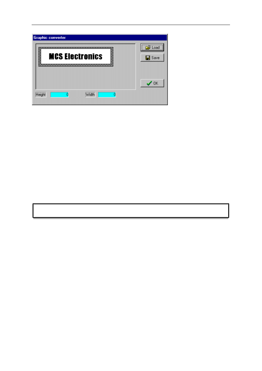
Tools Graphic Converter
The Graphic converter is intended to convert BMP files into BASCOM Graphic Files (BGF) that
can be used with Graphic LCD displays.
The following dialog box will be shown :
page -37-
© MCS Electronics, 1995-2006
To load a picture c lick the Load button.
The picture may be 64 pixels high and 240 pixels width.
When the picture is larger it will be adjusted.
You can use your favorite graphic tool to create the bitmaps and use the Graphic converter to
convert them into black and white images.
When you click the Save- button the pic ture will be converted into blac k and white.
Any non-white color will be c onverted into black.
The resulting file will have the BGF extension.
Press the Ok-button to return to the editor.
The picture can be shown with the ShowPic statement.
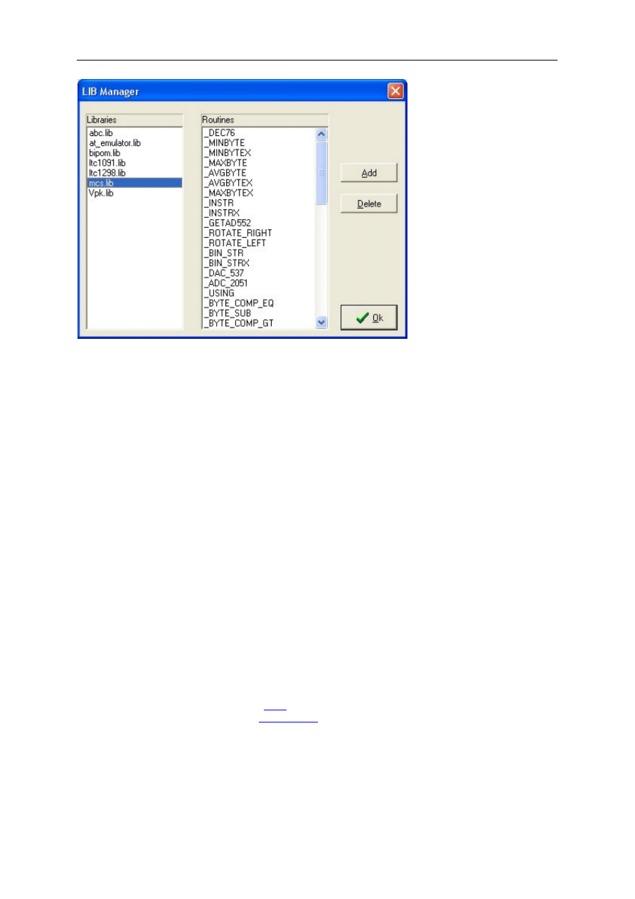
Tool LIB Manager
With this option you can add and remove ASM routines to the libraries.
The following windows will be displayed:
page -38-
© MCS Electronics, 1995-2006
Select a library first by clicking on it.
The Routines list will be refreshed with the contents of the selected library.
By clicking the Add button a dialog box will be shown to select the ASM file that contains the
ASM routine(s).
By clicking on the Delete button the selected Routine will be removed from the selected
library.
A library is an ASCII file that contains ASM routines.
Each routine must be preceded by the name of the routine between brackets.
Each routine must be ended with the [END] line.
A sample routine is shown here :
[_DEC76]
;decrease the register pair r6 and r7 with one
; return zero in ACC when r6r7 is zero
_Dec76:
Dec r6 ; dec LSB
Cjne r6,#255,*+4 ; if it was zero
Dec r7 ; we need to decrease r7 to
Mov a,r7 ; result into a
Orl a,r6 ; OR with r6 to see if it is zero
Ret
[END]
The library can be included with the
$LIB
directive.
A routine can be imported with the
directive.
$lib "mylib.lib"
$external _dec76

page -39-
© MCS Electronics, 1995-2006
Tools Triscent Converter
The Triscent Converter will convert a .H file generated by the Triscend program into a
triscend.DAT file that can be used by BASCOM.
The triscend.DAT file has an additional section named XBYTE.
[XBYTE]
CMAP0_TAR = ff00
CMAP0_ALT = ff01
The 3 lines above show the section and 2 entries. The triscend chips are configured by writing
to locations where normally XRAM is located.
BASCOM handles this automatic for you. So when you assign a value to CMAP0_TAR, the
value is written to location &HFF00 where the CMAP0_TAR register is located.
Reading this XRAM SFR will do the reverse.
At
www.triscend.com
you can find all info you need. Look for the E5 line of chips. These are
8051 compatible chips which can be configured with the Triscend software. You can for
example create 3 UARTS, add I2C, SPI, TIMERS etc.
So the E5 chip is hardware configurable by software!
After you created your
‘
chip
’
, you create the .H file and this file must be imported with the
Tools Triscend Convert option.
There is an evaluation KIT available from triscend. Another pro is that the chips have many
pins. So when your design needs a lot of I/O pins, I advise to look at these chips.
Tools Export to RTF
Action
Exports the current file to an RTF file.
Remarks
RTF files can be used in documents such as Word files. RTF files can also be used to show
code with colors on a web page. When your file has the name test.bas , a file with the name
test.rtf will be created in the same directory.
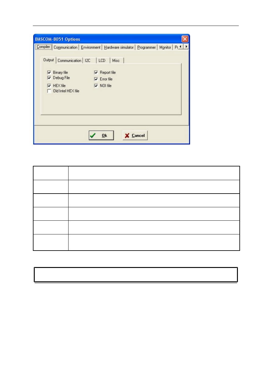
Options Compiler Output
page -40-
© MCS Electronics, 1995-2006
With this option you can specify which files must be created.
Binary file
This will generate a ROM-image of the program. Of course you can also store
it in a flashrom.
Debug file
This option will generate a DBG-file. It is used by the simulator. When you
don't use the simulator, you don't need to generate it.
Hex file
This is an Intel hex-file that is used by most programmers and monitor
programs.
Old Intel hex
file
This option will generate an old style Intel hex file and is used by the Elektor
monitor. If you choose this option, you must unselect the Hex File option.
Report file
This file contains info about the program, such as the baudrate, used
variables etc.
Error file
This file is generated when an error occurs. It holds the error descriptions.
When there is no error, the file will not be created.
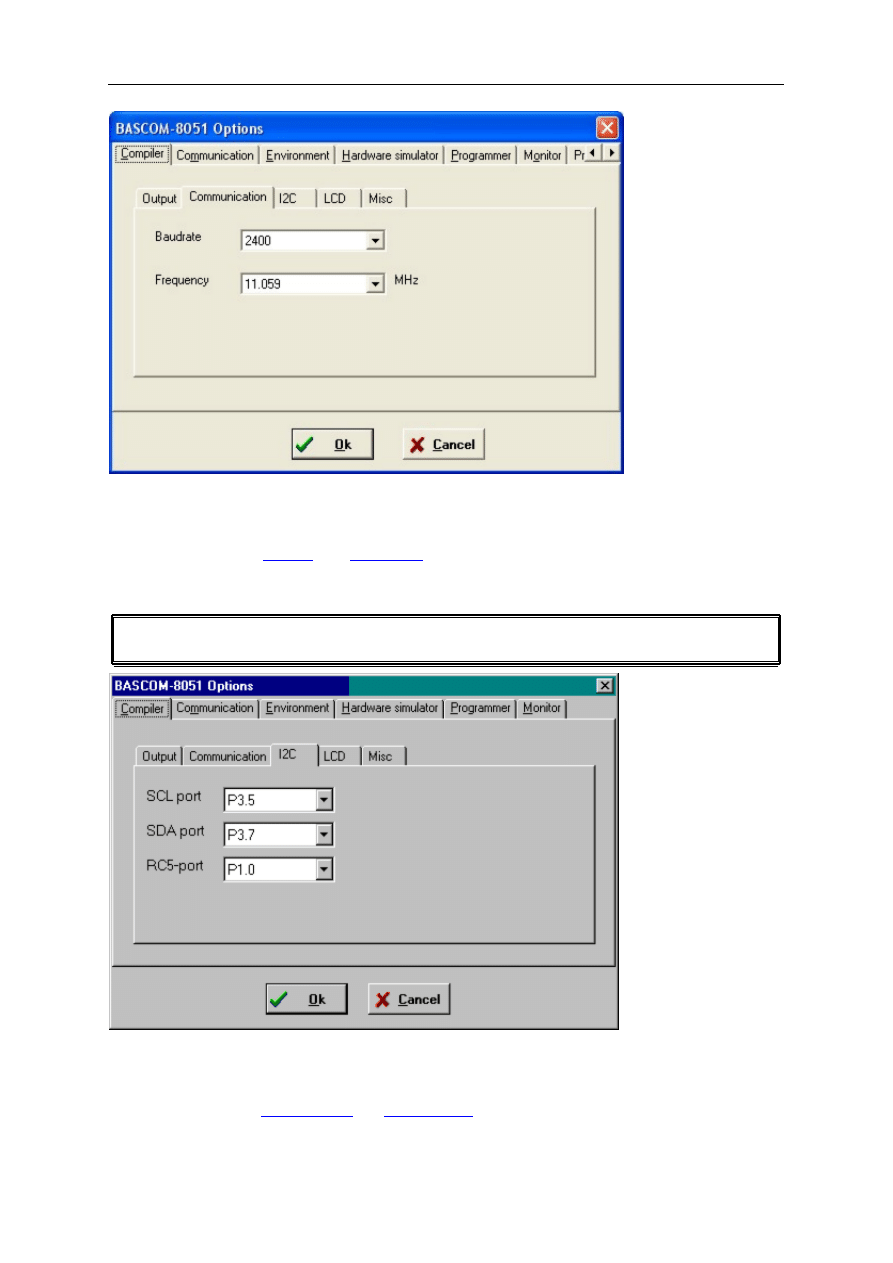
Options Compiler Communication
page -41-
© MCS Electronics, 1995-2006
With this options you can select the used crystal and the baud rate that must be used with
serial communications.
We advise to use the
compiler directives in your program.
This way the settings are stored in your sourcecode.
Options Compiler I2C
With this option you can select the port pins that serve as the SDA and SCL line for the I2C
statements.
You can also use the
CONFIG SDA
and
CONFIG SCL
statements.
page -42-
© MCS Electronics, 1995-2006
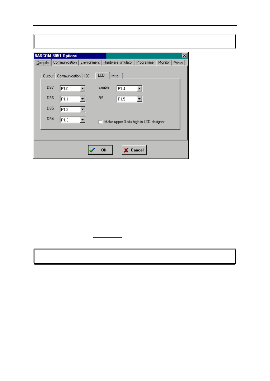
Options Compiler LCD
With this option you can select the port pins for the LCD display.
This only applies to the LCD statements when used in 4-bit mode and if the LCD display is
connected to the port pins.
You can also choose the port pins with the
statement.
In the 4-bit mode, only the highest nibble of the datalines is used.
To spare a pin for the R/W pin, reading from the LCD is not supported and you must connect
the R/W line to ground. See
for more info.
You can also use the LCD statements in the data bus mode.
Some LCD displays needs the upper 3 bits to be set high. So when you have this kind of
display you must select this option. When you select this option the LCD designer will set the
upper 3 bits high when the
DEFLCDCHAR
statement is generated.
Options Compiler Misc
With the miscellaneous options you can change the following
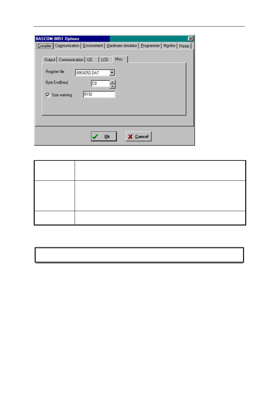
page -43-
© MCS Electronics, 1995-2006
Remarks
register file
Select the register file which is suitable for your target uP. The reg51.DAT
file is the common file that works for every uP, but doesn
’
t
’
have hardware
specific registers. You can use this file as a base for your own DAT file.
byte end
Specifies the last location of internal memory that can be used by the
compiler for storing variables. For uP's with 128 bytes of RAM set it to 70
for example. All space after this value is used for the stack. With the
simulator you can test if you run out of stack space. For uP's with 256 bytes
of internal RAM, you can use a higher value, F0 for example.
size warning
Select this option to enable the compiler to give a warning message when
the codesize exceeds the specified size.(decimal)
Options Communication
With this option you can modify the communication settings for the BASCOM terminal
emulator.
The following window will appear:
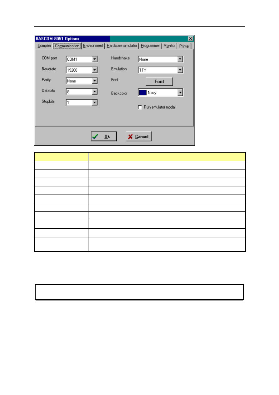
page -44-
© MCS Electronics, 1995-2006
Option
Remark
Comport
The comport of you computer to use.
Baud rate
The baud rate to use.
Parity
The parity to use.
Data bits
The number of data bits to use.
Stop bits
The number of stop bits to use.
Handshake
The handshake to use.
Emulation
The terminal emulation to use.
Font
Click the button to select the font and font color to use.
Backcolor
The background color to use (default blue)
Run emulator modal
Runs the terminal emulator in modal mode so you can use all key
combinations that are normally reserved to the IDE.
Note that the baud rate of the terminal emulator and the baudrate setting of the compiler
options, must be the same in order to work correctly.
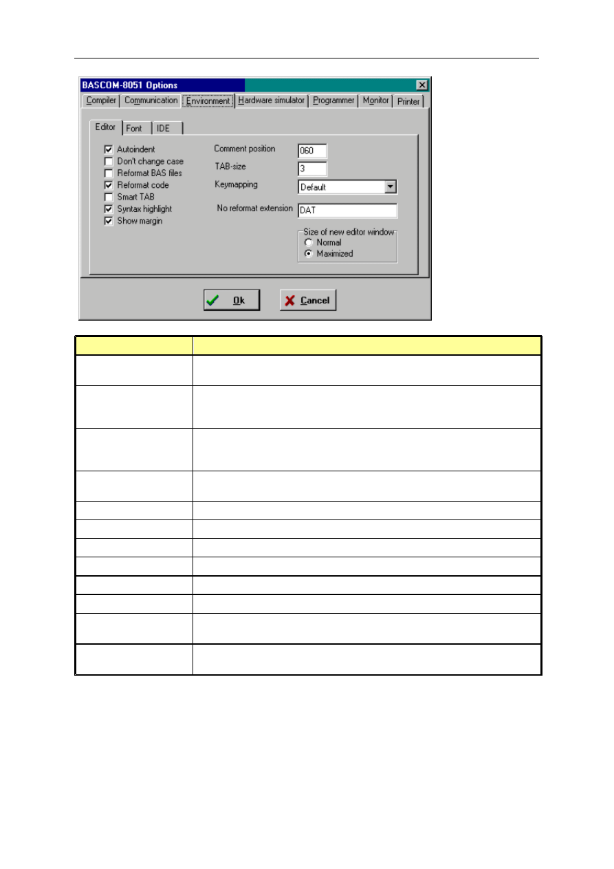
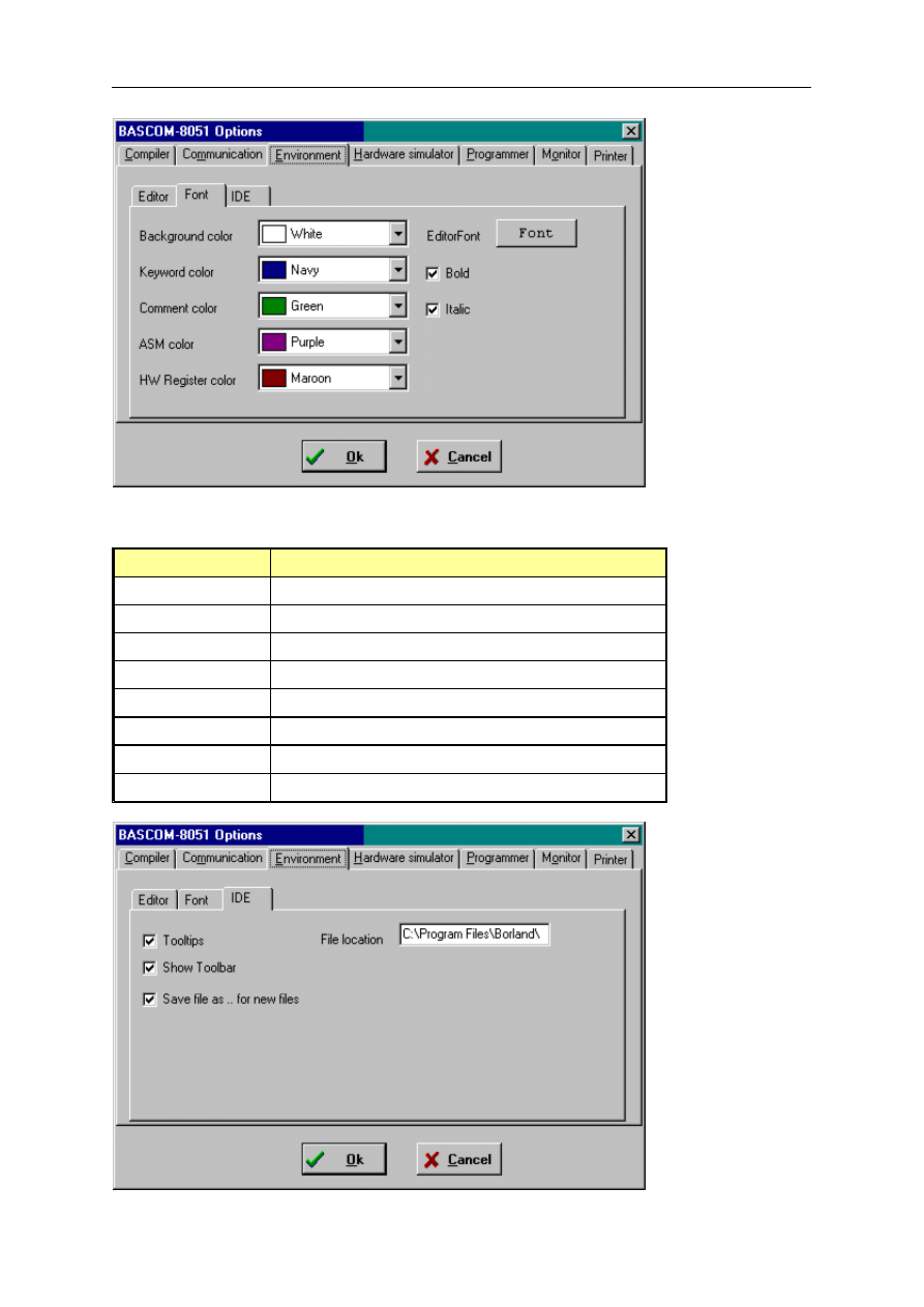
Options Environment
With this option you can modify the environment options.
page -45-
© MCS Electronics, 1995-2006
OPTION
DESCRIPTION
Auto indent
With auto indent, the cursor will be set to the same left margin as the
current line when you press return.
Don't change case
This option will not change the case of your line when you enabled
'Reformat code'. By default each first characters case is set to
uppercase.
Reformat BAS files
Reformat files when loading them into the editor. This is only
necessary when you are loading files that were created with another
editor. Normally you don't need to set this option.
Reformat code
Reformat code when entered in the editor. This will reformat the line
after you have set focus to a new line.
Smart tabs
Will look at the previous line for non spaces to position the cursor.
Syntax highlight
Enables/disables syntax highlighting
Show margin
Shows a margin at position 80.
Comment position
The right position of the comment.
Tabsize
The number of spaces equivalent to one tab.
Key mapping
Selects the behavior of the editor. Default behaves like Delphi.
No reformat extension Specifies file extensions separated by a space where the reformatting
is disabled. (for text files or dat files)
Size of new edit
window
Selects the size of the edit window when a file is opened.
page -46-
© MCS Electronics, 1995-2006
OPTION
DESCRIPTION
Background color
Background color of the editor
Keyword color
Color used to highlight keywords(statements)
Comment color
Color used to highlight comment
ASM color
Color used to highlight assembly
HW register color
Color used to highlight special function registers
Editor font
Font name of the editor
Bold
Check to display keywords in bold
Italic
Check to display comment in Italic

page -47-
© MCS Electronics, 1995-2006
OPTION
DESCRIPTION
Tool tips
Will enable/disable tool tips.
Show Toolbar
Will display/hide the toolbar of the IDE.
Save File As… for new
files
When you enable this option you will be prompted to give new files a
name before they will be saved with their default name.
File location
The path to the location of your BAS files. Normally Windows will use
My documents as a default.
Options hardware simulator
This option let you select the address of the LPT connected to the optional hardware
simulator.
Options Programmer
This option let you select the target programmer.
The supported programmers are :
PG2051
JPK Systems X-programmer
Peter Averill's TAFE programmer
SE-812
The auto flash options will automatic program a chip without displaying the programmer
window.
The auto verify option will verify automatically after each programming.
Options Monitor
With the monitor options you can select the monitor you use.
There are only a few monitor programs supported.
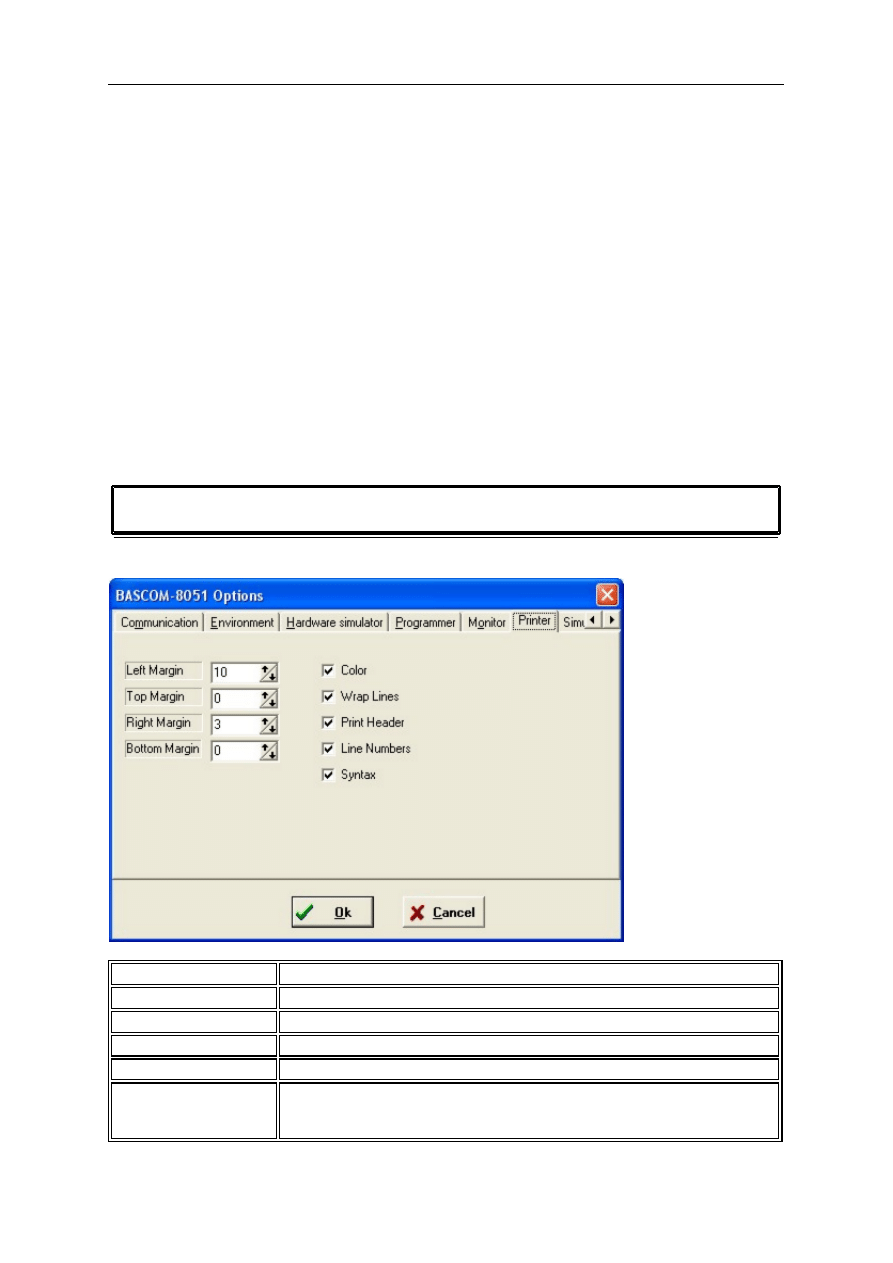
page -48-
© MCS Electronics, 1995-2006
o
Altair 535/537
o
Altair 552
o
Monitor hex upload
The Altair monitor needs special instructions and uses binary files.
The hex upload feature is ment for monitor programs that work with hex files.
You can upload a file to the target uP from the terminal emulator with the Upload file option.
For hex file based monitors there are 3 additional options:
o
monitor prefix, is sent before the hex file
o
monitor suffix, is sent after the hex file upload is completed
The prefix and suffix can contain returns or any ASCII character.
Use {asc} , to imbed an ASCII character. asc=0-255.
For example @{13} for the prefix, will send @ followed by a return.
o
monitor delay, must be specified in mSecs, and is the delaytime for each line sent.
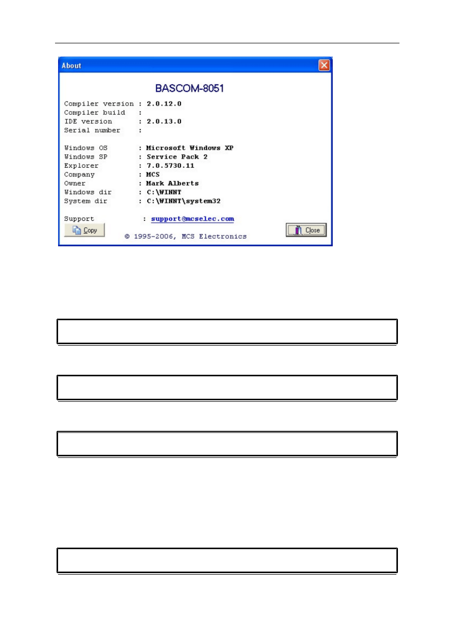
Options Printer
These options let you select the printer margins.
Left Margin
The left printer margin in mm
Top Margin
The top printer margin in mm
Right Margin
The right printer margin in mm
Bottom Margin
The bottom printer margin in mm
Color
Check to print in color.
Wrap Lines
Check when you want long lines to be wrapped. This is convenient
when you have long lines of source code that would otherwise would
not fit on the paper.

page -49-
© MCS Electronics, 1995-2006
Print Header
Check to print a header with file name and page number
Line Numbers
Check to print line numbers
Syntax
Check to use syntaxt highlighting options and colors
Window Cascade
Will cascade all editor windows so they will all be visible.
Window Tile
Window Tile will tile all editor windows.
Window arrange icons
Will arrange all iconized windows.
Window minimize all
Will minimize all editor windows.
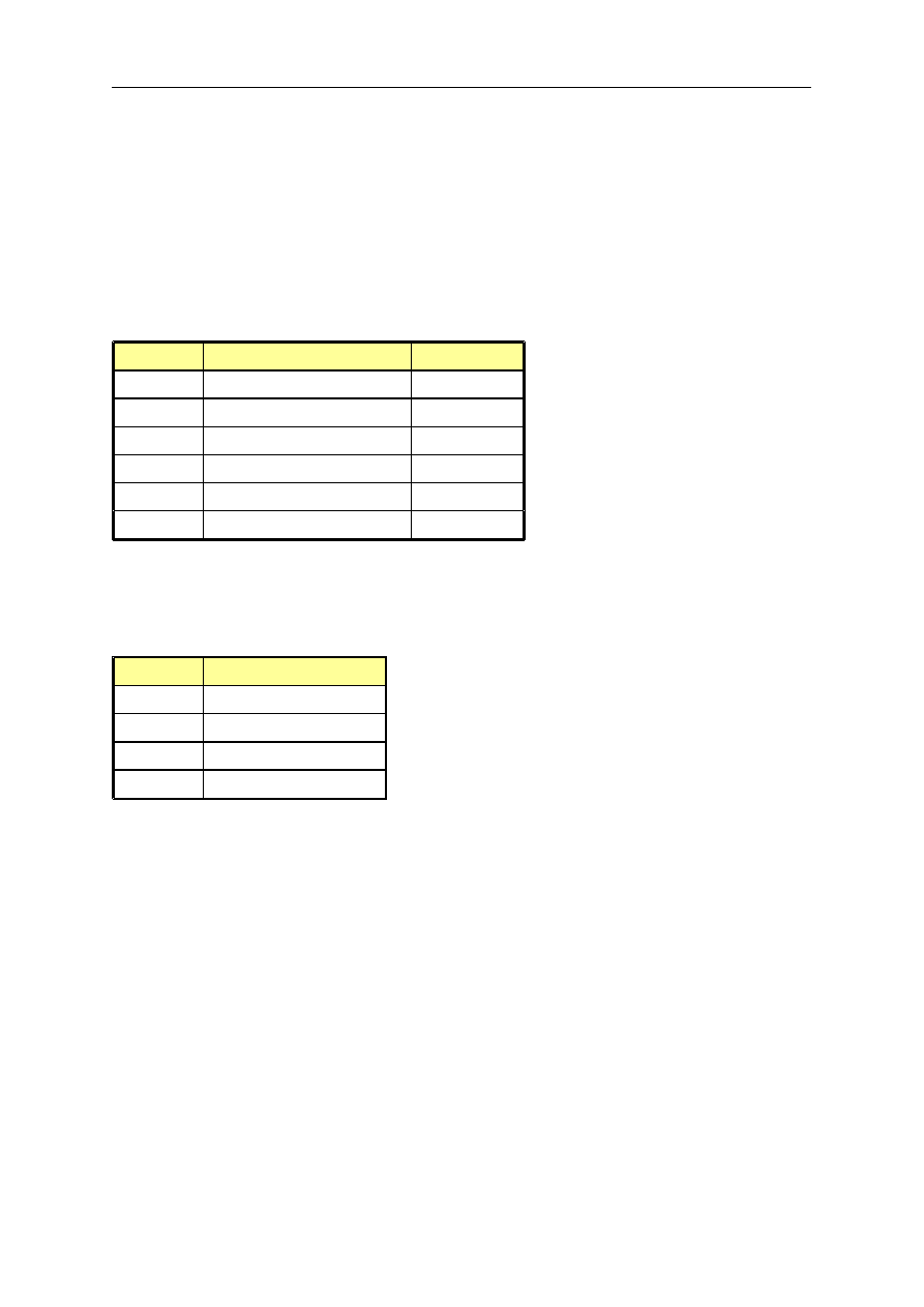
Help About
This option shows an about box as displayed below.
page -50-
© MCS Electronics, 1995-2006
Your serial number is shown in the about box.
You will need this when you have questions about the product.
The library version is also shown.
You can compare it with the one from our web site in case you need an update.
Click on the Ok-button to return to the editor.
Help Index
Will show the help index of BASCOM.
Help on help
Will bring up help about the Windows help system.
Help Shop
Action
This option will launch your default webbrowser and will open the MCS Electronics Shop.
We have a number of BASCOM-8051 KIT's and affordable 89Cx051 programmers from
Sample Electronics
Help Forum

page -51-
© MCS Electronics, 1995-2006
Action
This option will launch your default webbrowser and will open the MCS Forum.
The forum can be used to talk to other BASCOM users. You can get idea's there, discuss your
problems ans questions, and you can help other members.
Help Support
Action
This option will launch your default webbrowser and will open the MCS Support system.
The support system can be used to search the knowledge base.
Help Credits
Will launch this help file and show this topic.
MCS would like to thank the following people who have contributed to BASCOM development
:
Peter Averill from the Victoria University TAFE. Peter designed both the TAFE AT89C2051
programmer and the software to support it.
Antti from Silicon Studio Ltd. Antti designed the BlowIT ATA89C2051 programmer and
software to support it.
Jakub Jiricek, he designed the SPI-programmer and software to support it.
Francois du Plessis, he wrote a Windows version of Jacub's SPI-programmer software.
Henry Arndt (DL2TM) , he provided me with the source for his popular Atmel Programmer.

page -52-
© MCS Electronics, 1995-2006
Language fundamentals
Language Fundamentals
Characters from the BASCOM character set are put together to form labels, keywords,
variables and operators.
These in turn combine to form statements that make up a program.
This chapter describes the character set and the format of BASCOM program lines. In
particular, it discusses:
The specific characters in the character set and the special meanings of some characters.
The format of a line in a BASCOM program.
Line labels.
Program line length.
Character Set
The BASCOM BASIC character set consists of alphabetic characters, numeric characters, and
special characters.
The alphabetic characters in BASCOM are the uppercase letters (A-Z) and lowercase letters
(az) of the alphabet.
The BASCOM numeric characters are the digits 0-9.
The letters can be used as parts of hexadecimal numbers.
The following characters have special meanings in BASCOM statements and expressions:
Character
Description
ENTER
Terminates input of a line
Blank ( or space)
'
Single quotation mark (apostrophe)
*
Asterisks (multiplication symbol)
+
Plus sign
,
Comma
-
Minus sign
.
Period (decimal point)
/
Slash (division symbol) will be handled as \
:
Colon
"
Double quotation mark
;
Semicolon
<
Less than
=
Equal sign (assignment symbol or relational operator)
>
Greater than
\
Backslash (integer/word division symbol)

page -53-
© MCS Electronics, 1995-2006
The BASCOM program line
BASCOM program lines have the following syntax:
[[line-identifier]] [[statement]] [[:statement]] ... [[comment]]
Using Line Identifiers
BASCOM support one type of line-identifier; alphanumeric line labels:
An alphanumeric line label may be any combination of from 1 to 32 letters and digits,
starting with a letter and ending with a colon.
BASCOM keywords are not permitted. The following are valid alphanumeric line labels:
Alpha:
ScreenSUB:
Test3A:
Case is not significant. The following line labels are equivalent:
alpha:
Alpha:
ALPHA:
Line labels may begin in any column, as long as they are the first characters other than
blanks on the line.
Blanks are not allowed between an alphabetic label and the colon following it.
A line can have only one label.
BASCOM Statements
A BASCOM statement is either " executable" or " nonexecutable" .
An executable statement advances the flow of a programs logic by telling the program what
tot do next.
Non executable statement perform tasks such as allocating storage for variables, declaring
and defining variable types.
The following BASCOM statements are examples of nonexecutable statements:
o
REM or (starts a comment)
o
DIM
A " comment" is a nonexecutable statement used to clarify a programs operation and
purpose.
A comment is introduced by the REM statement or a single quote character(').
The following lines are equivalent:
PRINT " Quantity remaining" : REM Print report label.
PRINT " Quantity remaining" ' Print report label.
More than one BASCOM statement can be placed on a line, but colons(:) must separate
statements, as illustrated below.
FOR I = 1 TO 5 : PRINT " Gday, mate." : NEXT I
BASCOM LineLength
If you enter your programs using the built-in editor, you are not limited to any line length,
although it is advised to shorten your lines to 80 characters for clarity.

page -54-
© MCS Electronics, 1995-2006
Data Types
Every variable in BASCOM has a data type that determines what can be stored in the
variable. The next section summarizes the elementary data types.
Elementary Data Types
Bit (1/8 byte)
Byte (1 byte)
Bytes are stores as unsigned 8-bit binary numbers ranging in value from 0 to 255.
Integer (two bytes).
Integers are stored as signed sixteen-bit binary numbers ranging in value from -32,768
to +32,767.
Word (two bytes).
Words are stored as unsigned sixteen-bit binary numbers ranging in value from 0 to
65535.
Long (four bytes).
Longs are stored as signed 32-bit binary numbers ranging in value from -2147483648 to
2147483647.
Single
Singles are stored as signed 32 bit binary numbers.
String (up to 254 bytes).
Strings are stored as bytes and are terminated with a 0-byte.
A string dimensioned with a length of 10 bytes will occupy 11 bytes.
Variables can be stored internal (default) or external.
Variables
A variable is a name that refers to an object--a particular number.
A numeric variable can be assigned only a numeric value (either integer, word, byte long,
single or bit).
The following list shows some examples of variable assignments:
A constant value:
A = 5
C = 1.1
The value of another numeric variable:
abc = def
k = g
The value obtained by combining other variables, constants, and operators:
Temp = a + 5
Temp = C + 5
Variable Names
A BASCOM variable name may contain up to 32 characters.
The characters allowed in a variable name are letters and numbers.
The first character in a variable name must be a letter.
A variable name cannot be a reserved word, but embedded reserved words are allowed.
For example, the following statement is illegal because AND is a reserved word.

page -55-
© MCS Electronics, 1995-2006
AND = 8
However, the following statement is legal:
ToAND = 8
Reserved words include all BASCOM commands, statements, function names, internal
registers and operator names.
(see
, for a complete list of reserved words).
You can specify a hexadecimal or binary number with the prefix &H or &B.
a = &HA , a = &B1010 and a = 10 are all the same.
Before assigning a variable you must tell the compiler about it with the DIM statement.
Dim b1 As Bit, I as Integer, k as Byte , s As String * 10
You can also use
For example DEFINT c tells the compiler that all variables that are not dimensioned and that
are beginning with the character c are of the Integer type.
Expressions and Operators
This chapter discusses how to combine, modify, compare, or get information about
expressions by using the operators available in BASCOM.
Anytime you do a calculation you are using expressions and operators.
This chapter describes how expressions are formed and concludes by describing the following
kind of operators:
Arithmetic operators, used to perform calculations.
Relational operators, used to compare numeric values.
Logical operators, used to test conditions or manipulate individual bits.
Functional operators, used to supplement simple operators.
Expressions and Operators
An expression can be a numeric constant, a variable, or a single value obtained by combining
constants, variables, and other expressions with operators.
Operators perform mathematical or logical operations on values. The operators provides by
BASCOM can be divided into four categories, as follows:
1. Arithmetic
2. Relational
3. Logical
4. Functional
Arithmetic
Arithmetic operators are +, - , * and \.
Integer
Integer division is denoted by the backslash (\).
Example: Z = X \ Y
Modulo Arithmetic
Modulo arithmetic is denoted by the modulus operator MOD.
page -56-
© MCS Electronics, 1995-2006
Modulo arithmetic provides the remainder, rather than the quotient, of an integer division.
Example: X = 10 \ 4 : remainder = 10 MOD 4
Overflow and division by zero
Division by zero, produces an error.
At this moment there is no message, so you have to insure yourself that such wont
happen.
Relational Operators
Relational operators are used to compare two values as shown in the table below.
The result can be used to make a decision regarding program flow.
Operator
Relation Tested
Expression
=
Equality
X = Y
<>
Inequality
X <> Y
<
Less than
X < Y
>
Greater than
X > Y
<=
Less than or equal to
X <= Y
>=
Greater than or equal to
X >= Y
Logical Operators
Logical operators perform tests on relations, bit manipulations, or Boolean operators.
There are four operators in BASCOM, they are :
Operator
Meaning
NOT
Logical complement
AND
Conjunction
OR
Disjunction
XOR
Exclusive or
It is possible to use logical operators to test bytes for a particular bit pattern.
For example the AND operator can be used to mask all but one of the bits
of a status byte, while OR can be used to merge two bytes to create a particular binary
value.
Example
A = 63 And 19
PRINT A
A = 10 Or 9
PRINT A
Output
16
11
Floating point
Single numbers conform to the IEEE binary floating point standard.
An eight-bit exponent and 24 bit mantissa are supported.
Using four bytes, the format is shown below:

page -57-
© MCS Electronics, 1995-2006
31 30________23 22______________________________0
s exponent mantissa
The exponent is biased by 128. Above 128 are positive exponents and below are negative.
The sign bit is 0 for positive numbers and 1 for negative. The mantissa is stored in hidden bit
normalized format so that 24 bits of precision can be obtained.
All mathematical operations are supported by the single.
You can also convert a single to an integer or word or vise versa:
Dim I as Integer, S as Single
S = 100.1 'assign the single
I = S 'will convert the single to an integer
Take a look at the single.bas example for more information.
Arrays
An array is a set of sequentially indexed elements having the same type. Each element of an
array has a unique index number that identifies it. Changes made to an element of an array
do not affect the other elements.
The index must be a numeric constant, a byte, an integer or a word. This means that an
array can hold 65535 elements as a maximum. The minimum value is 1 and not zero as in
QB.
Arrays can be used on each place where a 'normal' variable is expected but there are a few
exceptions.
These exceptions are shown in the help topics.
Note that there are no BIT arrays in BASCOM-8051.
Example:
Dim a(10) as byte 'make an array named a, with 10 elements (1 to 10)
Dim c as Integer
For C = 1 To 10
a(c) = c 'assign array element
Print a(c) 'print it
Next
Strings
Strings can be up to 254 characters long in BASCOM.
To save memory you must specify how long each string must be with the DIM statement.
Dim S As String * 10
This will reserve space for the string S with a length of 10 bytes. The actual length is 11
bytes because a nul(0) is used to terminate the string.
You can concatenate string with the + sign.
Dim S As String * 10 , Z As String * 10
S = "test"
Z = S + "abc" + var
In QB you can assign a string with a value and add the original string (or a part of it) too :
S = "test"
S = "a" + s
This will result in the string "atest"
In BASCOM-8051 this is NOT possible because this would require a copy of the string.
In BASCOM the string S is assigned with "a" and on that moment the original string S is
destroyed. So you must make a copy of the string yourself in the event you need this
functionality.

page -58-
© MCS Electronics, 1995-2006

page -59-
© MCS Electronics, 1995-2006
BASCOM Language Reference
BASCOM STATEMENTS
-1-
1WRESET, 1WREAD, 1WWRITE
1WSEARCHFIRST
-COMPILER DIRECTIVES-
#IF
#ELSE
#ENDIF
$ASM - $END ASM
$INCLUDE
-A-
-B-
BITWAIT
BCD
BREAK

page -60-
© MCS Electronics, 1995-2006
-C-
CALL
CLOSE
CLS
CHR
CONFIG
CONST
COUNTER
CPEEK
CURSOR
-D-
DATA
DEBOUNCE
DECR
DECLARE
DEFINT
DEFBIT
DEFBYTE
DEFLCDCHAR
DEFWORD
DELAY
DIM
DISABLE
DISPLAY
DO
-E-
-F-
-G-
GET
GETAD
GETAD2051
GETRC
GETRC5
GOSUB
GOTO
-H-
-I-
I2CRECEIVE

page -61-
© MCS Electronics, 1995-2006
I2CSTART
I2CSTOP
I2CRBYTE
I2CWBYTE
IDLE
IF
INCR
INKEY
INP
INPUT
INPUTBIN
INPUTHEX
INSTR
-L-
LCDHEX
LEFT
LEN
LOAD
LOCATE
LOOKUP
LOOKUPSTR
LOOP
LOW
LOWW
LOWERLINE
-M-
MAKEDEC
MAKEBCD
MAKEINT
MAX
MID
MIN
MOD
-N-
NEXT
-O-
-P-
P1,P3
PEEK
POKE
PSET
POWERDOWN
PRINT
PRINTBIN
PRINTHEX
PRIORITY
PUT
-R-

page -62-
© MCS Electronics, 1995-2006
READ
READMAGCARD
REM
REPLACE
RESET
RESTORE
RETURN
RIGHT
RND
ROTATE
-S-
SELECT
SET
SHIFT
SHIFTCURSOR
SHIFTIN
SHIFTOUT
SHIFTLCD
SHOWPIC
SOUND
SPACE
SPC
SPIIN
SPIOUT
START
STOP
STOP TIMER
STR
STRING
SUB
SWAP
-T-
-U-
UCASE
-V-
VAL
VARPTR
-W-
WAIT
WAITKEY
WAITMS
WHILE .. WEND
#IF
Action
Conditional compilation directive that tests for a condition.

page -63-
© MCS Electronics, 1995-2006
Syntax
#IF
test
[
#ELSE
]
#ENDIF
Remarks
test
An expression to test for. The expression may contain defined constants.
Conditional compilation is used to include parts of your program. This is a convenient way to
build different files depending on some constant values.
Note that unlike the IF statement, the #IF directive does not expect a THEN.
You may nest conditions to 25 levels.
The use of #ELSE is optional.
See Also
Example
CONST DEMO = 1 ' 0 = normal , 1= demo
#IF Demo
Print "Demo program"
#ELSE
Print "Full version"
#ENDIF
Since the constant DEMO is assigned with the value 1, the compiler will compile only the line
: Print "Demo program" . Code between #else and #endif is not compiled!
When you change the constant DEMO to 0, the other line will be compiled.
#ELSE
Action
Conditional compilation directive that tests for a NOT condition.
Syntax
#IF
test
#ELSE
#ENDIF
Remarks
test
An expression to test for. The expression may contain defined constants.
Conditional compilation is used to include parts of your program. This is a convenient way to
build different files depending on some constant values.
Note that unlike the IF statement, the #IF directive does not expect a THEN.
You may nest conditions to 25 levels.

page -64-
© MCS Electronics, 1995-2006
The use of #ELSE is optional. The code between #ELSE and #ENDIF will be compiled when
the expression is not true.
See Also
Example
CONST DEMO = 1 ' 0 = normal , 1= demo
#IF Demo
Print "Demo program"
#ELSE
Print "Full version"
#ENDIF
Since the constant DEMO is assigned with the value 1, the compiler will compile only the line
: Print "Demo program" . Code between #else and #endif is not compiled!
When you change the constant DEMO to 0, the other line will be compiled.
#ENDIF
Action
Conditional compilation directive that ends a test.
Syntax
#IF
test
[
#ELSE
]
#ENDIF
Remarks
Test
An expression to test for. The expression may contain defined constants.
Conditional compilation is used to include parts of your program. This is a convenient way to
build different files depending on some constant values.
Note that unlike the IF statement, the #IF directive does not expect a THEN.
You may nest conditions to 25 levels.
The use of #ELSE is optional.
Note that #ENDIF must be written as #ENDIF, not as #END IF
See Also
Example
CONST DEMO = 1 ' 0 = normal , 1= demo
#IF Demo
Print "Demo program"
#ELSE
Print "Full version"
#ENDIF

page -65-
© MCS Electronics, 1995-2006
Since the constant DEMO is assigned with the value 1, the compiler will compile only the line
: Print "Demo program" . Code between #else and #endif is not compiled!
When you change the constant DEMO to 0, the other line will be compiled.
1WRESET,1WREAD,1WWRITE
Action
These routines can be used to communicate with Dallas Semiconductors 1Wire-devices.
Syntax 1 for use with the CONFIG 1WIRE statement
1WRESET
1WWRITE
var1 [ , bytes]
var2 =
1WREAD
( [ bytes])
Syntax 2 for use with multiple devices/pins
1WRESET
pin
1WWRITE
var1 [ , bytes] pin
var2 =
1WREAD
( [ bytes] [, pin])
var2 =
1WREAD
( [pin])
Pin is the port pin to use with the device such as P1.1
Remarks
1WRESET
Reset the 1WIRE bus. The error variable ERR will return 1 if an error
occurred.
1WWRITE var1
Sends the value of var1 to the bus.
Optional is the number of bytes that mist be sent. var1 is a numeric
variable or constant.
var2 = 1WREAD() Reads a byte from the bus and places it into var2.
Optional is the number of bytes that must be read. var2 is a number
variable.
Example
'--------------------------------------------------------------
' 1WIRE.BAS
' demonstrates 1wreset, 1wwrite and 1wread()
' pull-up of 4K7 required to VCC from P.1
' DS2401 serial button connected to P1.1
'--------------------------------------------------------------
Config
1wire =
P1
.1
'use this pin
Dim
Ar(8)
As
Byte
, A
As
Byte
, I
As
Byte
1wreset
'reset the device
Err
'print error 1 if error
1wwrite &H33
'read ROM command
For
I = 1
To
8

page -66-
© MCS Electronics, 1995-2006
Ar(i) = 1wread()
'place into array
Next
For
I = 1
To
8
Printhex
Ar(i);
'print output
Next
'linefeed
'You can also use multiple pins
'alias the pin first
Tsensor
Alias
P1
.2
'the optional argument specifies the pin to use
1wreset Tsensor
'reset
1wwrite &H33 Tsensor
'write value to
Tsensor
1wwrite Ar(1) , 2 Tsensor
'write 2 bytes
to Tsensor
A = 1wread(tsensor)
'return byte
from Tsensor
Ar(1) = 1wread(2 ,
P1
.2)
'read 2 bytes
from Tsensor
End
1WIRECOUNT
Action
This statement returns the number of 1wire devices found on the bus.
Syntax
var2
=
1WIRECOUNT
(array
)
Remarks
var2
A word variable that is assigned with the number if found 1wire devices on the
bus.
Array
A variable or array that should be at least 8 bytes long. It is used to store the
1wire ID
’
s while counting.
The 1wireCount function uses the 1wSearchFirst() and 1wSearchNexy functions internally.
See also
1WIRE
,
1WSEARCHFIRST
,
1WSEARCHNEXT
Example
'---------------------------------------------------------------------------
' 1wirecount.bas

page -67-
© MCS Electronics, 1995-2006
' (c)1995-2006 MCS Electronics
' demonstration of using multiple devices
'--------------------------------------------------------------------------
'chip we use
$regfile
=
"89s8252.dat"
'crystal attached
$crystal
= 12000000
'baud rate
$baud
= 4800
'wait for 500 mili secs
Waitms
500
'the pins we use
'connect a 4K7 resistor from the data pin to VCC
Config
1wire =
P1
.0
'we need an array of 8 bytes to hold the result
Dim
Ar(8)
As
Byte
'we also need a counter variable and a word variable
Dim
I
As
Byte
, W
As
Word
'some ids of 1wire chips I tested
' 01 51 B5 8D 01 00 00 56
' 01 84 B3 8D 01 00 00 E5
"start"
'get the number of connected 1wire device
W = 1wirecount(ar(1))
'print if there was an error and how many sensors are available
"ERR "
;
Err
;
" count "
; W
'now get the data from the first 1wire device on the bus
Ar(1) = 1wsearchfirst()
'print the ID
For
I = 1
To
8
Printhex
Ar(i);
Next
'I assume that there are more than 1 1wire devices
Do
'get the next device
Ar(1) = 1wsearchnext()
For
I = 1
To
8
Printhex
Ar(i);
Next
Loop
Until
Err
= 1
'when ERR is 1 it means there are no more devices

page -68-
© MCS Electronics, 1995-2006
' IMPORTANT : 1wsearchfirst and next functions do require that you use the
SAME array
'In this example this is ar(1)
'once you know the ID, you can address a specific device
End
1WSEARCHFIRST
Action
This statement reads the first ID from the 1wire bus into a variable array.
Syntax
var2
=
1WSEARCHFIRST
(
)
Remarks
var2
A variable or array that should be at least 8 bytes long and that will be
assigned with the 8 byte ID from the first 1wire devic e on the bus.
The 1wireSearchFirst() func tion must be c alled once to initiate the ID retrieval process. After
the 1wireSearchFirst() func tion is used you should use succ essive function calls to the
1wireSearchNext function to retrieve other ID's on the bus.
A string can not be assigned to get the values from the bus. This bec ause a nul may be
returned as a value and the nul is also used as a string term inator.
We advice to use a byte array as shown in the exam ple.
The ERR bit is set when there are no 1wire devices found.
See also
Example
'----------------------------------------------------------------------
' 1wirecount.bas
' (c) 1995-2006 MCS Electronics
' demonstration of using multiple devices
'--------------------------------------------------------------------------
'chip we use
$ r e g f i l e
=
"89s8252.dat"
'crystal attached
$ c r y s t a l
= 12000000
'baud rate
$ b a u d
= 4800
'wait for 500 mili secs
W a i t m s
500
'the pins we use
'connect a 4K7 resistor from the data pin to VCC
C o n f i g
1wire =
P1
.0

page -69-
© MCS Electronics, 1995-2006
'we need an array of 8 bytes to hold the result
D i m
Ar(8)
A s
B y t e
'we also need a counter variable and a word variable
D i m
I
A s
B y t e
, W
A s
W o r d
'some ids of 1wire chips I tested
' 01 51 B5 8D 01 00 00 56
' 01 84 B3 8D 01 00 00 E5
P r i n t
"start"
'get the number of connected 1wire device
W = 1wirecount(ar(1))
'print if there was an error and how many sensors are available
P r i n t
"ERR "
;
E r r
;
" count "
; W
'now get the data from the first 1wire device on the bus
Ar(1) = 1wsearchfirst()
'print the ID
F o r
I = 1
T o
8
P r i n t h e x
Ar(i);
N e x t
P r i n t
'I assume that there are more than 1 1wire devices
D o
'get the next device
Ar(1) = 1wsearchnext()
F o r
I = 1
T o
8
P r i n t h e x
Ar(i);
N e x t
P r i n t
L o o p
U n t i l
E r r
= 1
'when ERR is 1 it means there are no more devices
' IMPORTANT : 1wsearchfirst and next functions do require that you use the SAME
array
'In this example this is ar(1)
'once you know the ID, you can address a specific device
E n d
1WSEARCHNEXT
Action
This statement reads the next ID from the 1wire bus into a variable array.
Syntax
var2
=
1WSEARCHNEXT
(
)
Remarks
var2
A variable or array that should be at least 8 bytes long that will be
assigned with the 8 byte ID from the next 1wire devic e on the bus.
The 1wireSearchFirst() func tion must be c alled once to initiate the ID retrieval process. After
the 1wireSearchFirst() func tion is used you should use succ essive function calls to the
1wireSearchNext function to retrieve other ID's on the bus.

page -70-
© MCS Electronics, 1995-2006
A string can not be assigned to get the values from the bus. This bec ause a nul may be
returned as a value and the nul is also used as a string term inator.
I would advice to use a byte array as shown in the exam ple.
The ERR variable is set when there are no m ore devices found.
See also
Example
'---------------------------------------------------------------------------
' 1wirecount.bas
' (c) 1995-2006 MCS Electronics
' demonstration of using multiple devices
'--------------------------------------------------------------------------
'chip we use
$regfile
=
"89s8252.dat"
'crystal attached
$crystal
= 12000000
'baud rate
$baud
= 4800
'wait for 500 mili secs
Waitms
500
'the pins we use
'connect a 4K7 resistor from the data pin to VCC
Config
1wire =
P1
.0
'we need an array of 8 bytes to hold the result
Dim
Ar(8)
As
Byte
'we also need a counter variable and a word variable
Dim
I
As
Byte
, W
As
Word
'some ids of 1wire chips I tested
' 01 51 B5 8D 01 00 00 56
' 01 84 B3 8D 01 00 00 E5
"start"
'get the number of connected 1wire device
W = 1wirecount(ar(1))
'print if there was an error and how many sensors are available
"ERR "
;
Err
;
" count "
; W
'now get the data from the first 1wire device on the bus
Ar(1) = 1wsearchfirst()
'print the ID
For
I = 1
To
8
Printhex
Ar(i);
Next

page -71-
© MCS Electronics, 1995-2006
'I assume that there are more than 1 1wire devices
Do
'get the next device
Ar(1) = 1wsearchnext()
For
I = 1
To
8
Printhex
Ar(i);
Next
Loop
Until
Err
= 1
'when ERR is 1 it means there are no more devices
' IMPORTANT : 1wsearchfirst and next functions do require that you use the
SAME array
'In this example this is ar(1)
'once you know the ID, you can address a specific device
End
$ASM - $END ASM
Action
Start of inline assembly code block.
Syntax
$ASM
Remarks
Use $ASM together with $END ASM to insert a block of assembler code in your BASIC code.
You can also insert ASM code by preceding the line with the ! sign.
See also
Example
Dim c as Byte
$ASM
Mov r0,#{C} ;address of c
Mov a,#1
Mov @r0,a ;store 1 into var c
$END ASM
Print c
End

page -72-
© MCS Electronics, 1995-2006
$BAUD
Action
Instruct the compiler to override the baud rate setting from the options menu.
Syntax
$BAUD
= var
Remarks
Var
The baud rate that you want to use. Var must be a numeric
constant.
When you want to use a crystal/baud rate that can't be selected from the options, you can
use this compiler directive.
You must also use the
These statements always work together.
In the generated report you can view which baud rate is actually generated.
But the baud rate is only shown when RS-232 statements are used like PRINT, INPUT etc.
See also
Example
$baud
= 2400
$crystal
= 14000000
' 14 MHz crystal
"Hello"
End
$BGF
Action
Binds a BASCOM Graphic File into the program for use with Graphic LCD displays.
Syntax
$BGF
"file"
Remarks
"file" is the name of the BGF file that is included in the program,
BMP files can be converted with the
Tools Graphic Converter
.
See also
SHOWPIC

page -73-
© MCS Electronics, 1995-2006
Example
'-----------------------------------------------------------------------------
-
' (c) 1995-2006 MCS Electronics
' GLCD.BAS
' Sample to show support for T6963C based graphic display
' Only 240*64 display is supported with 30 columns(yet)
' At the moment the display can only be used in PORT mode
' Connection :
' P1.0 - P1.7 to DB0-DB7 of LCD
' P3.2 to FS, font select of LCD can be hard wired too
' P3.5 to CE, chip enable of LCD
' P3.4 to CD, code/data select of LCD
' P3.6 to WR of LCD
' P3.7 to RD of LCD
'A future version will allow external data access too which also uses RD and
WR
'The display from www.conrad.com needs a negative voltage for the contrast.
'I used two 9 V batteries
'-----------------------------------------------------------------------------
-
'configure the LCD display
Config
Graphlcd = 240 * 64 , Port =
P1
, Ce =
P3
.5 , Cd =
P3
.4 , Cols = 30
'dimension some variables used by the DEMO
Dim
X
As
Byte
, Y
As
Byte
'
Reset
P3
.2
'8 bit wide char
is 30 columns
'The following statements are supported:
Cls
'will clear
graphic and text
'cls TEXT will clear only the text
'cls GRAPH will clear only the graphic part
'To init the display manual you can use:
'Lcdinit
'But this should not be needed as it is initilised at start up.
'Locate is supported and you can use 1-8 for the row and 1-30 for the column
Locate
1 , 1
'cursor control is the same as for normal LCD
Cursor
On
Blink
'And to show some text you can use LCD
Lcd
"Hello world"
'Note that the cursor position is not adjusted. You can set it with locate
'Now comes the fun part for using a graphic LCD

page -74-
© MCS Electronics, 1995-2006
'We can display a BMP file. You may use MSPAINT or any other tool that can
create
'a BMP file. With the Graphic converter from the Tools Menu you can convert
the file
'into a BGF file. (BASCOM GRAPHICS FILE). The conversion will convert all non
white
'pixels to BLACK.
'To display the BGF file you use the SHOWPIC statement that needs an X and Y
parameter
'the third param is the label where the data is stored.
'The position must be divideble by 8 because this is the way the display
handles the data
Showpic
0 , 0 , Picture1
'And we use the PSET known from QB to set or reset a single pixel
'A value of 0 means clear the pixel and 1 means set the pixel
'create a block
For
X = 0
To
10
For
Y = 0
To
10
Pset
X , Y , 1
Next
Next
'You could remove it too
For
X = 0
To
10
For
Y = 0
To
10
Step
2
Pset
X , Y , 0
Next
Next
'A simple scope or data logger could be made with PSET !
'We hope to get an AN from an inspired user :-)
End
'label for the picture
Picture1:
'$BGF includes the data from the specified file
$bgf
"samples\mcs.bgf"
$CRYSTAL
Action
Instruct the compiler to override the crystal frequency options setting.
Syntax

page -75-
© MCS Electronics, 1995-2006
$CRYSTAL
= var
Remarks
var
Frequency of the crystal.
var : Constant.
When you want to use an unsupported crystal/baud rate you can use this compiler directive.
When you do, you must also use the corresponding
These statements always work together.
See also
Example
$baud
= 2400
$crystal
= 14000000
' 14 MHz crystal
"Hello"
End
$DEFAULT XRAM
Action
Compiler directive to handle each dimensioned variable as XRAM variable.
Syntax
$DEFAULT XRAM
Remarks
When you are using many XRAM variables it make sense to set this option, so you don't have
to type XRAM each time.
To dimension a variable to be stored into IRAM, specify IRAM in that case.
See Also
Example
$default
Xram
Dim
X
As
Integer
'will go to XRAM
Dim
Z
As
Iram
Integer
'will be stored in IRAM
$EXTERNAL
Action
Compiler directive that instructs the compiler to include the specified assembler routines.

page -76-
© MCS Electronics, 1995-2006
Syntax
$EXTERNAL
myrout [, other]
Remarks
The $EXTERNAL directive is used internally by the compiler in order to enable the customizing
of the assembler routines by the user.
You can use it to include your own assem bler routines. At the moment using $EXTERNAL will
always include the routine no matter if it is used or not.
See also
Example
$LIB "mylib.lib"
$EXTERNAL _dec76
$INCLUDE
Action
Includes an ASCII file in the program at the current position.
Syntax
$INCLUDE
"file"
Remarks
file
Name of the ASCII file which must contain valid BASCOM statements.
This option can be used if you make use of the same routines in
many programs. You can write modules and include them into your program.
If there are changes to make you only have to change the module file, not all
your BASCOM programs.
You can only include ASCII files!
Example
'--------------------------------------------------------------
' (c) 1995-2006 MCS Electronics
'--------------------------------------------------------------
' file: INCLUDE.BAS
' demo: $INCLUDE
'--------------------------------------------------------------
"INCLUDE.BAS"
$include
"123.bas"
'include file that prints Hello
"Back in INCLUDE.BAS"
End

page -77-
© MCS Electronics, 1995-2006
$IRAMSTART
Action
Compiler directive to specify starting internal memory location.
Syntax
$IRAMSTART
= constant
Remarks
Constant
A constant with the starting value (0-255)
See also
Example
$NOINIT
$NOSP
$IRAMSTART = &H60 'first usable memory location
SP = 80
DIM I As Integer
$LARGE
Action
Instructs the compiler that LCALL statements must be used.
Syntax
$LARGE
Remarks
Internally when a subroutine is called the ACALL statement is used.
The ACALL instruction needs only 2 bytes (the LCALL needs 3 bytes)
The ACALL statement however can only address routines with a maximal offset of 2048
within the page. AT89C2051 chips will have no problems with that.
When code is generated for another uP, the subroutine being called can be further away and
you will receive an error. With the $LARGE statement you instruct the compiler to use the
LCALL statement which can address the full 64K address space.
Example
$LARGE 'I received an error 148 so I need this option

page -78-
© MCS Electronics, 1995-2006
$LIB
Action
Compiler directive that instruc ts the c ompiler to look for assembler routines in the specified
LIB file.
Syntax
$LIB
"myrout.LIB"
Remarks
The $LIB directive is used internally by the compiler in order to enable the customizing of the
assembler routines by the user.
You can use it to specify your own libraries. You can for example copy the mcs.lib file to a
new file named mylib.lib and delete the content of the mcs.lib file. This way the compiler will
use your routines. The mcs.lib file must exist in the \LIB subdirectory and that is why you
may not delete it.
Always make a backup of the mcs.lib file before you change it.
It is not encouraged to change the mcs.lib file itself other than making a dummy because
updates will contain more asm routines and you have to change everything for each update.
See also
Example
$LIB "mylib.lib"
$EXTERNAL _dec76
$LCD
Action
Instruct the compiler to generate code for 8-bit LCD displays attached to the data bus.
Syntax
$LCD
= [&H]address
Remarks
address
The address where must be written to, to enable the LCD display.
The db0-db7 lines of the LCD must be connected to the datalines D0-D7.
The RS line of the LCD must be connected to the address line A0.
On systems with external RAM/ROM it makes more sense to attach the LCD
to the data bus. With an address decoder you can select the LCD display.

page -79-
© MCS Electronics, 1995-2006
See Also
Example
$lcd
= &HA000
'writing to this address will make the E line of the LCD high.
Cls
Lcd
"Hello world"
End
$LCDRS
Action
Instruct the compiler to generate code for 8-bit LCD displays attached to the data bus.
Syntax
$LCDRS
= [&H]address
Remarks
Address
The address where must be written to, to enable the LCD display and the RS
of the LCD.
The db0-db7 lines of the LCD must be connected to the data lines D0-D7.
The RS line of the LCD must be connected to the address line A0 by default.
When it is connected to another address line you can specify $LCDRS
On systems with external RAM/ROM it makes more sense to attach the LCD
to the data bus. With an address decoder you can select the LCD display.
See Also
$LCD
Example
$lcd
= &H8000
'writing to this address will make the E line of the LCD high.
$lcdrs
= &H8002
'writing to this address will make the RS line of the LCD high.
Cls
Lcd
"Elektor"
End
$MAP
Action
Generates info in the report file with hexadecimal address of each source line.

page -80-
© MCS Electronics, 1995-2006
Syntax
$MAP
Remarks
For debugging it can be useful to know at which address a source line begins.
See also
NONE
Example
$MAP
Print "Hello"
Print "Test"
Will generate the following section in the report file :
Code map
-----------------------------------------------------------
Line Address(hex)
-----------------------------------------------------------
2 52
3 69
5 80
$NOBREAK
Action
Instruct the compiler that BREAK statements must not be compiled.
Syntax
$NOBREAK
Remarks
With the BREAK statement, you can generate a reserved opcode that is used by the simulator
to pause the simulation.
When you want to compile without these opcodes you don't have to remove the BREAK
statement: you can use the $NOBREAK statement to achieve the same.
See also
BREAK
Example
$nobreak
Break
' this isn't compiled into code so the simulator will not pause

page -81-
© MCS Electronics, 1995-2006
End
$NOINIT
Action
Instruct the compiler that no initialization must be performed.
Syntax
$NOINIT
Remarks
BASCOM initializes the processor depending on the used statements.
When you want to handle this by yourself you can specify this with the compiler directive
$NOINIT.
The only initialization that is always done is the setting of the stack pointer and the
initialization of the LCD display (if LCD statements are used).
When you have selected the Altair as a monitor in the Monitor options, the following code will
be generated:
Mov IE,#255
Mov scon,#82
This because the Altair monitor needs this code despite of the $NOINIT.
See also
Example
$NONIT
'your program goes here
End
$NONAN
Action
Compiler directive for changing nan (not a number) into 0.0
Syntax
$NONAN
Remarks
A single can return a NAN when it is not considered to be a number.
With the $NONAN directive 0.0 will be returned.

page -82-
© MCS Electronics, 1995-2006
See also
NONE
Example
NONE
$NONULL
Action
Compiler directive for changing the behavior of the DATA statements.
Syntax
$NONULL
= value
Remarks
value
0 for default behavior. And -1 for special behavior
When a string is stored with a DATA statement, a null is added to indicate the string end. In
some situations you might not want this. When you write a custom routine to work with a
long string for example. With $NONULL = -1 , the additional null byte is not added. To switch
back to normal mode use a value of 0.
See also
NONE
Example
$nonull = -1
Lbl:
Data
"test"
,
"this"
Lbl2:
$nonull = 0
'normal mode
Data
"test"
,
"this"
$NORAMCLEAR
Action
Instruct the compiler that the internal RAM should not be cleared at start up.
Syntax
$NORAMCLEAR
Remarks
BASCOM clears the internal memory after a reset. When you don
’
t want this behavior you
can use the $NORAMCLEAR compiler directive.

page -83-
© MCS Electronics, 1995-2006
See also
NONE
Example
$NORAMCLEAR
‘your code goes here
End
$NOSP
Action
Instruct the compiler that the stack pointer must not be set.
Syntax
$NOSP
Remarks
BASCOM initializes the processor depending on the used statements.
When you want to handle this by yourself you can specify this with the compiler directive
$NOINIT.
The only initialization that is always done is the setting of the stack pointer and the
initialization of the LCD display (if LCD statements are used).
With the $NOSP directive the stack will not be initialized either.
See also
$NOINIT
Example
$NOSP
$NOINIT
End
$OBJ
Action
Includes Intel object code.

page -84-
© MCS Electronics, 1995-2006
Syntax
$OBJ
obj
Remarks
obj is the objectcode to include.
In some cases it can be useful to include object code. This object code can be generated with
other tools.
Example
$OBJ D291 'this is equivalent to SET P1.1
$RAMSIZE
Action
Specifies the size of the external RAM memory.
Syntax
$RAMSIZE
= [&H] size
Remarks
Size
Size of external RAM memory chip.
size : Constant.
See also
Example
$ROMSTART = &H4000
$RAMSTART = 0
$RAMSIZE = &H1000
DIM x AS XRAM Byte 'specify XRAM to store variable in XRAM
$RAMTRON
Action
Tell the compiler to use SPI memory as XRAM.
Syntax
$RAMTRON

page -85-
© MCS Electronics, 1995-2006
Remarks
address
The (hex)-address where the data is stored.
Or the lowest address which enables the RAM chip.
You can use this option when you want to run your code in systems
with external RAM memory.
Ramtron (www.ramtron.com) sell EEPROM's that are as fast as normal RAM chips.
They can be written billions of times. The $ramtron directive will use such as ramtron device
as xram device. This only works for the AT89S8252. You only add a ramtron EEPROM to the
hardware SPI lines and when you dim a variable as XRAM, the EEPROM will be used to store
and retrieve the data.
This is a convenient way to add more memory without adding an address decoder and a RAM
chip. Since the EEPROM is housed in a 8 pins chip it will make your design simple.
Note however that it is best practice that writing to such a XRAM variable must not be
excessive. The datasheet of the Ramtron chips show that you can write it many times and in
effect it will take years until you reach the limit.
Note that $RAMTRON does not need a parameter.
ASM
When XRAM is written with Movx @dptr,a , a call will be made to _WriteRamtron. Nothing is
destroyed or returned.
When XRAM is read with Movx a,@dptr , a call will be made to _ReadRamtron. Value is
returned in ACC as movx a,@dptr would do too.
Both routines are in the mcs.lib file. Both routines call _Wait_Spif to wait for the SPI, SPIF
bit.
Example
'-------------------------------------------------------
' (c) 1995-2006 MCS Electronics
' RAMTRON.BAS
' This example shos how to use the www.ramtron.com eeprom
' to be used a XRAM
'-------------------------------------------------------
'it works only for the 8252
$regfile = "89s8252.dat"
'tell the compiler about ramtron
'THIS SAMPLE WILL NOT SIMULATE beause of the $RAMTON directive
'Suggestion is to add the directive when you simulated your program
$ramtron
'dim some variables
Dim X As Byte , X1 As Byte
'Now dim XRAM. This will be stored in the Ramtron devic
Dim Z(10) As Xram Byte

page -86-
© MCS Electronics, 1995-2006
Wait 1
'I used P1.3 for the CS so the mcs.lib also uses this pin
'P1.4 could be used too but it needs a change in the mcs.lib
'This sample works actually!
'But since I also have code like *+4 it will not work always
'I need to rewrite that code. Let me know when some routines dont work
'with the $ramtron directive
'fill the data
For X = 1 To 10
Z(x) = X
Next
'print the data
For X = 1 To 10
Print Z(x)
Next
End
$RAMSTART
Action
Specifies the location of the external RAM memory.
Syntax
$RAMSTART
= [&H]address
Remarks
address
The (hex)-address where the data is stored.
Or the lowest address which enables the RAM chip.
You can use this option when you want to run your code in systems
with external RAM memory.
Address must be a numeric constant.
See also
$RAMSIZE
Example
$ROMSTART = &H4000
$RAMSTART = 0

page -87-
© MCS Electronics, 1995-2006
$RAMSIZE = &H1000
$REGFILE
Action
Instructs the compiler to use the specified register file.
Syntax
$REGFILE
= "file"
Remarks
File
The name of the register file to use.
The $REGFILE statement must be placed before any other executable statements or compiler
directives.
See also
NONE
Example
'comment is no problem before the $REGFILE statement
$REGFILE = "8052.DAT" 'use the 8052.DAT file
$ROMSTART
Action
Specifies the location of the ROM memory.
Syntax
$ROMSTART
= [&H] address
Remarks

page -88-
© MCS Electronics, 1995-2006
address
The (hex)-address where the code must start.
Default is 0. This value will be used when $ROMSTART is not specified.
You can use this option when you want to test the code in RAM.
The code must be uploaded and placed into the specified address and can
be called from a monitor program.
The monitor program must relocate the interrupts to the correct address!
When $ROMSTART = &H4000 is specified the monitor program must
perform a LJMP instruction. For address 3 this must be &H4003. Otherwise
interrupts can not be handled correctly. But that is up to the monitor
program.
See also
Example
$ROMSTART = &H4000 'ROM enabled at 4000 hex
$SERIALINPUT
Action
Specifies that serial input must be redirected.
Syntax
$SERIALINPUT = label
Remarks
Label
The name of the assembler routine that must be called when an character is
needed from the INPUT routine. The character must be returned in ACC.
With the redirection of the INPUT command, you can use your own routines.
This way you can use other devices as input devices.
Note that the INPUT statement is terminated when a RETURN code (13) is received.
See also
$SERIALOUTPUT
Example
$SERIALINPUT = Myinput
'here goes your program
END
!myinput:
;perform the needed actions here
mov a, sbuf ;serial input buffer to acc
ret

page -89-
© MCS Electronics, 1995-2006
$SERIALINPUT2LCD
Action
This compiler directive will redirect all serial input to the LCD display instead of echoing to
the serial port.
Syntax
$SERIALINPUT2LCD
Remarks
You can also write your own custom input or output driver with the $SERIALINPUT and
$SERIALOUTPUT statements, but the $SERIALINPUT2LCD is handy when you use a LCD
display.
See also
Example
$serialinput2lcd
Dim
V
As
Byte
Cls
Input
"Number "
, V
'this will go to the LCD display
$SERIALOUTPUT
Action
Specifies that serial output must be redirected.
Syntax
$SERIALOUTPUT
= label
Remarks
label
The name of the assembler routine that must be called when a character is
sent to the serial buffer (SBUF).
The character is placed into ACC.
With the redirection of the PRINT and other serial output related commands, you can use
your own routines.
This way you can use other devices as output devices.
See Also

page -90-
© MCS Electronics, 1995-2006
Example
$SERIALOUTPUT = MyOutput
'here goes your program
END
!myoutput:
;perform the needed actions here
mov sbuf, a ;serial output buffer (default)
ret
$SIM
Action
Generates code without the actual waiting loops in order to speed up the simulator.
Syntax
$SIM
Remarks
When simulating the WAIT statement, you will experience that it takes a long time to
execute. You can also switch off the updating of variables/source which costs time, but an
alternative is the $SIM directive.
You must remove the $SIM statement when you want to place your program into a
chip/EPROM.
See also
Example
$SIM 'don't make code for WAIT and WAITMS
WAIT 2 'the simulator is faster now
$TIMEOUT
Action
Compiler directive to specify that the TIMEOUT option is used with serial input.
Syntax
$TIMEOUT

page -91-
© MCS Electronics, 1995-2006
Remarks
$TIMEOUT will modify the serial input routine so that it enables you to use the TIMEOUT with
the INPUT, INPUTBIN, INPUTHEX etc. statements.
See also
Example
$TIMEOUT
DIM Name as string * 10
REM Now we can use theTIMEOUT option
INPUT "Name " , name TIMEOUT = 100000 'enable time out
INPUT "Name ", name 'wait until <13> pressed.
$WAIT
Action
Will insert a one second delay in the startup code.
Syntax
$WAIT
Remarks
When using the AT89C8252 ISP facility it is needed that the chip waits 1 second after reset.
Otherwise it can occur that the chip can not be programmed serial anymore.
Do not confuse $WAIT with the WAIT statement.
$WAIT is only needed for the AT89C8252 !
See also
NONE
Example
$WAIT 'for at89c8252 only
ALIAS
Action
Indicates that the variable can be referenced with another name.

page -92-
© MCS Electronics, 1995-2006
Syntax
newvar
ALIAS
oldvar
Remarks
Oldvar
Name of the variable such as P1.1
Newvar
New name of the variable such as direction
Aliasing port pins can give the pin names a more meaningful name.
You can also ALIAS a variable: M ALIAS var.0 for example.
See also
Example
Direction
Alias
P1
.1
'now you can refer to P1.1 with the variable direction
Set
Direction
'has the same effect as SET P1.1
Dim
A
As
Byte
M
Alias
A.0
N
Alias
A.1
Set
M
Set
N
If
M = N
Then
"Both bits are set"
End
If
End
ABS
Action
Returns the absolute value of a numeric variable.
Syntax
var =
ABS
(var2)
Remarks
var
Variable that is assigned the absolute value of var2. Var must be a
numeric variable.
Var2
The source variable to retrieve the absolute value from. Var2 must be an
integer or long.
The absolute value of a number is always positive.
See also
NONE

page -93-
© MCS Electronics, 1995-2006
Example
Dim a as Integer, c as Integer
a = -1000
c = Abs(a)
Print c
End
Output
1000
ASC
Action
Convert a string into its ASCII value.
Syntax
var =
ASC
(string)
Remarks
var
Target variable that is assigned.
String
String variable or constant to retrieve the ASCII value from.
var : Byte, Integer, Word, Long.
string : String, Constant.
Note that only the first character of the string will be used.
When the string is empty, a zero will be returned.
See also
Example
Dim
A
As
Byte
, S
As
String
* 10
S =
"Abc"
A =
Asc
(s)
A
End
Output
65
AVG

page -94-
© MCS Electronics, 1995-2006
Action
Returns the average value of a byte array.
Syntax
var =
AVG
( ar(1) )
Remarks
Var
Numeric variable that will be assigned with the lowest value of the array.
ar()
The first array element of the array to return the lowest value of.
At the moment AVG() works only with BYTE arrays.
Support for other data types will be added too.
See also
Example
Dim ar(10) As Byte
Dim bP as Byte
For bP = 1 to 10
ar(bP) = bP
Next
bP = Avg(ar(1))
Print bP
End
BAUD
Action
Instruct the compiler to set a new baud rate at run time.
Syntax
BAUD
= var
Remarks
Var
The baud rate that you want to use.
var : Constant.
When you want to use a crystal/baud rate that can't be selected from the options, you can
assign this special variable.
Do not confuse it with the
$BAUD
directive!
See also

page -95-
© MCS Electronics, 1995-2006
Example
$BAUD = 2400
$CRYSTAL = 14000000 ' 14 MHz crystal
PRINT "Hello"
BAUD = 9600
Print "Hello"
END
BCD
Action
Converts a variable into its BCD value.
Syntax
BCD
( var )
LCD
BCD
( var )
Remarks
Var
Variable to convert. This must be a numeric variable or constant.
When you want to use a I2C clock device which stores its values as BCD values you can use
this function to print the value correctly.
BCD() will displays values with a trailing zero.
The BCD() function is intended for the PRINT/LCD statements.
Use the MAKEBCD function to convert variables.
See also
MAKEBCD
,
MAKEDEC
Example
Dim
A
As
Byte
A = 65
Lcd
A
Lowerline
Lcd
Bcd
(a)
End
BITWAIT
Action
Wait until a bit is set or reset.

page -96-
© MCS Electronics, 1995-2006
Syntax
BITWAIT
x SET | RESET
Remarks
x
Bit variable or internal register like P1.x , where x ranges form 0-7.
When using bit variables be sure that they are set/reset by software.
When you use internal registers that can be set/reset by hardware such as P1.0 this doesn't
apply.
See also
NONE
Example
Dim
A
As
Bit
Bitwait
A ,
Set
'wait until bit a is set
Bitwait
P1
.7 ,
Reset
'wait until bit 7 of Port 1 is 0.
End
ASM
BITWAIT P1.0 , SET will generate :
Jnb h'91,*+0
BITWAIT P1.0 , RESET will generate :
Jb h'91,*+0
BREAK
Action
Generates a reserved opcode to pause the simulator.
Syntax
BREAK
Remarks
You can set a breakpoint in the simulator but you can also set a breakpoint from code using
the BREAK statement.
Be sure to remove the BREAK statements when you debugged your program or use the
$NOBREAK directive.
The reserved opcode used is A5.
See also
$NOBREAK

page -97-
© MCS Electronics, 1995-2006
Example
PRINT "Hello"
BREAK 'the simulator will pause now
End
CALL
Action
Call and execute a subroutine.
Syntax
CALL
Test [(var1, var-n)]
Remarks
var1
Any BASCOM variable or constant.
var-n
Any BASCOM variable or constant.
Test
Name of the subroutine. In this case Test
With the CALL statement you can call a procedure or subroutine.
As much as 10 parameters can be passed but you can also call a subroutine without
parameters.
For example : Call Test2
The call statement enables you to implement your own statements.
You don't have to use the CALL statement:
Test2 will also call subroutine test2
When you don't supply the CALL statement, you must leave out the parenthesis.
So Call Routine(x,y,z) must be written as Routine x,y,z
See also
DECLARE
,
SUB
Example
Dim
A
As
Byte
, Bb
As
Byte
Declare
Sub
Test(bb
As
Byte
)
A = 65
Call
Test(a)
'call test with parameter A
Test A
'alternative call
End
Sub
Test(bb
As
Byte
)
'use the same variable as the declared one
Lcd
Bb
'put it on the LCD
Lowerline
Lcd
Bcd
(bb)
End
Sub

page -98-
© MCS Electronics, 1995-2006
CHR
Action
Convert a byte, Integer/Word variable or a constant to a character.
Syntax
CHR
(var)
s =
CHR
(var)
Remarks
Var
Byte, Integer/Word variable or numeric constant.
S
A string variable.
When you want to print a character to the screen or the LCD display,
you must convert it with the CHR() function.
See also
Example
Dim
A
As
Byte
A = 65
Lcd
A
Lowerline
Lcdhex
A
Lcd
Chr
(a)
End
CLS
Action
Clear the LCD display and set the cursor home.
Syntax
CLS
Syntax for graphic LCD
CLS
TEXT
CLS
GRAPH
CLS
BOTH
Remarks
Clearing the LCD display does not clear the CG-RAM in which the custom characters are
stored.

page -99-
© MCS Electronics, 1995-2006
See also
Example
Cls
Lcd
"Hello"
Wait
5
Cls
End
CONST
Action
Declares a symbolic constant.
Syntax
CONST
symbol = value
Remarks
symbol
The name of the symbol.
Value
The value to assign to the symbol.
Assigned constants consume no program memory.
The compiler will replace all occurrences of the symbol with the assigned value.
Value may also be an expression that uses other defined constants.
The functions that may be used for the expressions are : ASC , ABS, ATN, COS , EXP , FIX,
INT , LOG, RND , SGN , SIN ,SQR , TAN.
Operators are : AND, OR ,XOR +, - , / , \ , ^ , * , NOT , > , < , = , >= , <=,<> , (, )
See also
Example
'----------------------------------------------------
' (c) 1995-2006 MCS Electronics
' CONST.BAS
'----------------------------------------------------
Dim
A
As
Const
5
'declare a as a constant
Dim
B1
As
Const
&B1001
Dim
S
As
Single
'Or use the new preferred syntax
Const
Cbyte = &HF
Const
Cint = -1000
Const
Csingle = 1.1
Const
Cstring =
"test"
S = Csingle
S ;
" "
; Cstring
Waitms
A
'wait for 5 milliseconds
A
B1
End

page -100-
© MCS Electronics, 1995-2006
CONFIG
The config statement configures all kind of hardware related statements.
Select one of the following topics to learn more about a specific config statement.
CONFIG TIMER0, TIMER1
CONFIG TIMER2
(for 8052 compatible chips)
CONFIG LCD
CONFIG LCDBUS
CONFIG LCDPIN
CONFIG BAUD
CONFIG 1WIRE
CONFIG SDA
CONFIG SCL
CONFIG DEBOUNCE
CONFIG WATCHDOG
CONFIG SPI
CONFIG I2CDELAY
CONFIG MICROWIRE
CONFIG SERVOS
CONFIG ADUC812
CONFIG GETRC
CONFIG PRINT
CONFIG GRAPHLCD
CONFIG 1WIRE
Action
Configure the pin to use for 1WIRE statements.
Syntax
CONFIG 1WIRE
= pin
Remarks
pin
The port pin to use such as P1.0
See also
1WRESET
,
1WREAD
,
1WWRITE
Example
Config 1WIRE = P1.0 'P1.0 is used for the 1-wire bus
1WRESET
'reset the bus
CONFIG ADUC812

page -101-
© MCS Electronics, 1995-2006
Action
Configures the ADUC812 microprocessor.
Syntax for ADC
Config ADUC812
= ADCON , MODE = mode, CLOCK = clock , AQUISITION = aq ,
TIMER2 = tm , EXTRIG = value
Syntax for DAC
Config ADUC812
= DAC , MODE = mode, RANGE0 = r0 , RANGE1 = r1 , CLEAR0 = clr0 ,
CLEAR1 = clr1 , SYNC = sync, POWER0 = pwr0, POWER1 = pwr1
Remarks ADC
mode
POWERDOWN, NORMAL, PDNE, STANDBY.
PDNE means POWERDOWN if not executing a conversion cycle.
clock
This is a constant that specifies the clock division of the master
clock. It may be 1,2,4 or 8.
An ADC conversion will require 16 ADC clocks in addition to the
selected number of aquisition clocks.
aq
This is a constant that specifies the time available for the input/track
hold amplifier to acquire the input signal.
It may be in range from 1-4. 1 Acquisition clock is enough for an
impedance up to 8K
tm2
The TIMER2 can be ENABLED or DISABLED. When enabled the
timer2 overflow serves as a trigger for the AD conversion.
value
The external trigger may be ENABLED or DISABLED. When enabled
the external pin 23 (CONVST) can start the conversion while it is
low.
Remarks DAC
Mode
The DAC can be in 8 bit mode or 12 bit mode. So the parameter may
be 8 or 12. Both DACS are set with this parameter.
r0
The DAC0 range can be set to VDD or VREF. With VDD the range is
from 0-VDD. For VREF it is 0-VREF.
r1
The DAC1 range can be set to VDD or VREF. With VDD the range is
from 0-VDD. For VREF it is 0-VREF
c lr0
This parameter when TRUE will clear the DAC0. This will set the
output voltage to 0 V.
c lr1
This parameter when TRUE will clear the DAC1. This will set the
output voltage to 0 V
Sync
May be ENABLED or DISABLED. While enabled the DAC outputs as
soon as the DACxL SFR's are written. The user can simutaneously
update both DAC's by first updating the DACxL/H SFR's while SYNC
is disabled. Both DACs will then update when the SYNC is enabled.
pwr0
This parameter when ON will power ON the DAC0. When OFF the
DAC0 is powered OFF.

page -102-
© MCS Electronics, 1995-2006
pwr1
This parameter when ON will power ON the DAC1. When OFF the
DAC1 is powered OFF
CONFIG BAUD
Action
Configure the uP to select the intern baud rate generator.
This baud rate generator is only available in the 80515, 80517, 80535, 80537 and compatible
chips.
Syntax
CONFIG BAUD
= baud rate
Remarks
Baud rate
Baud rate to use : 4800 or 9600
Example
CONFIG BAUD = 9600 'use internal baud generator
Print "Hello"
End
CONFIG BAUD1
Action
Configure the uP to select the internal baud rate generator for serial channel 1.
This baud rate generator is only available in the 80517 and 80537.
Syntax
CONFIG BAUD1
= baudrate
Remarks
Baudrate
Baud rate to use : 2048 - 37500
The 80517 and 80537 have 2 serial ports on board.
See also
CONFIG BAUD
Example

page -103-
© MCS Electronics, 1995-2006
CONFIG BAUD1 = 9600 'use internal baud generator
OPEN "Com2:" for Binary as #1
Print #1, "Hello"
Close #1
End
CONFIG DEBOUNCE
Action
Configures the delay time for the DEBOUNCE statement.
Syntax
CONFIG DEBOUNCE
= time
Remarks
time
A numeric constant which specifies the delay time in mS.
When the debounce time is not configured, 25 mS will be used as a default.
Note that the delay time is based on a 12 MHz clock frequency.
See also
Example
Config Debounce = 25 mS '25 mS is the default
CONFIG I2CDELAY
Action
Configures the delay for the I2C clock.
Syntax
CONFIG I2CDELAY
= value
Remarks
Value
A numeric constant.
1 will generate the default clock.
0 will generate a higher clock and >=2 will generate a lower clock
frequency.

page -104-
© MCS Electronics, 1995-2006
By default the following delay routine is called with an ACALL :
Delay5:
Nop
Ret
For 12 MHz, there is a 1 MHz system clock. So not counting the other statement, the minimal
delay is 4 * 2 = 8 cycles.
The I2Cdelay value will insert the number of specified NOP instructions.
By default the settings are right for all I2C devices and when working with a 12 MHz crystal.
See also
Example
CONFIG I2CDELAY = 0 'we need a higher clock
CONFIG GETRC
Action
Configures the GETRC() charge time.
Syntax
Config GETRC
= time
Remarks
Time
The time in milli seconds to charge the capacitor
See also
CONFIG GRAPHLCD
Action
Configures the Graphical LCD display.
Syntax
Config GRAPHLCD
= type , PORT = mode, CE = pin , CD = cd , COLS = 30
Remarks

page -105-
© MCS Electronics, 1995-2006
Type
This must be one of the following :
240 * 64
240 * 128
mode
This is the name of the port that is used to put the data on the LCD data pins
db0-db7.
P1 for example.
Ce
The name of the pin that is used to enable the chip on the LCD.
Cd
The name of the pin that is used to control the CD pin of the display.
Cols
The number of columns for use as text display. The current code is written for
30 columns only.
This is a first implementation for Graphic support. It is based on the T6963C chip
that is used in many displays. At the moment there is only support for pin mode.
That is, the LCD is controlled by changing logic levels on the pins.
Memory mapped or bus mode will be added later. But pin mode can be used with any
micro so that is why this is first implemented.
I used the following connections:
P1.0 to P1.7 to DB0-DB7 of the LCD
P3.2 to FS, font select of LCD can be hard wired too
P3.5 to CE, chip enable of LCD
P3.4 to CD, code/data select of LCD
P3.6 to WR of LCD, write
P3.7 to RD of LCD, read
The LCD used from www.conrad.de needs a negative voltage for the contrast.
Two 9V batteries were used with a pot meter.
The FS (font select) must be set low to use 30 columns and 8x8 fonts.
It may be connected to ground. This pin is not used by the software routines.
The current asm code only support 30 columns. You can change it however to use 40
c olumns.
The T6963C displays have both a graphical area and a text area. They can be used
together. The routines use the XOR mode to display both text and graphics layered
over each other.
The statements that can be used with the graphical LCD are :
CLS
, will clear the graphic display and the text display
CLS GRAPH will clear only the graphic part of the display
CLS TEXT will only clear the text part of the display
CLS BOTH is the same as CLS and will clear both text and graphics.
LOCATE
row,column Will place the cursor at the specified row and column
The row may vary from 1 to 8 and the column from 1 to 30.
CURSOR
ON/OFF BLINK/NOBLINK can be used the same way as for text

page -106-
© MCS Electronics, 1995-2006
displays.
can also be the same way as for text displays.
can also be used the same way as for text display
New are:
X, Y , Label where X and Y are the column and row and Label is the label
where the picture info is placed.
X, Y , color Will set or reset a pixel. X can range from 0-239 and Y from 9-63.
When color is 0 the pixel will turned off. When it is 1 the pixel will be set on.
"file.bgf" 'inserts a BGF file at the current location
$TIFF is removed from the Help but it still supported this version. $BGF should be
used however.
Example
'------------------------------------------------------------------------------
' (c) 1995-2006 MCS Electronics
' GLCD.BAS
' Sample to show support for T6963C based graphic display
' Only 240*64 display is supported with 30 columns(yet)
' At the moment the display can only be used in PORT mode
' Connection :
' P1.0 - P1.7 to DB0-DB7 of LCD
' P3.2 to FS, font select of LCD can be hard wired too
' P3.5 to CE, chip enable of LCD
' P3.4 to CD, code/data select of LCD
' P3.6 to WR of LCD
' P3.7 to RD of LCD
'A future version will allow external data access too which also uses RD and WR
'The display from www.conrad.com needs a negative voltage for the contrast.
'I used two 9 V batteries
'------------------------------------------------------------------------------
'configure the LCD display
Config Graphlcd = 240 * 64 , Port = P1 , Ce = P3.5 , Cd = P3.4 , Cols = 30
'dimension some variables used by the DEMO
Dim X As Byte , Y As Byte
'
Reset P3.2 '8 bit wide char is 30 columns
'The following statements are supported:
Cls 'will clear graphic and text
'cls TEXT will clear only the text

page -107-
© MCS Electronics, 1995-2006
'cls GRAPH will clear only the graphic part
'To init the display manual you can use:
'Lcdinit
'But this should not be needed as it is initilised at start up.
'Locate is supported and you can use 1-8 for the row and 1-30 for the column
Locate 1 , 1
'cursor control is the same as for normal LCD
Cursor On Blink
'And to show some text you can use LCD
Lcd "Hello world"
'Note that the cursor position is not adjusted. You can set it with locate
'Now comes the fun part for using a graphic LCD
'We can display a BMP file. You may use MSPAINT or any other tool that can create
'a BMP file. With the Graphic converter from the Tools Menu you can convert the file
'into a BGF file. (BASCOM GRAPHICS FILE). The conversion will convert all non white
'pixels to BLACK.
'To display the BGF file you use the SHOWPIC statement that needs an X and Y parameter
'the third param is the label where the data is stored.
'The position must be divideble by 8 because this is the way the display handles the data
Showpic 0 , 0 , Picture1
'And we use the PSET known from QB to set or reset a single pixel
'A value of 0 means clear the pixel and 1 means set the pixel
'create a block
For X = 0 To 10
For Y = 0 To 10
Pset X , Y , 1
Next
Next
'You could remove it too
For X = 0 To 10
For Y = 0 To 10 Step 2
Pset X , Y , 0
Next
Next
page -108-
© MCS Electronics, 1995-2006
'A simple scope or data logger could be made with PSET !
'We hope to get an AN from an inspired user :-)
End
'label for the picture
Picture1:
'$BGF includes the data from the specified file
$bgf "samples\mcs.bgf"
CONFIG LCDPIN
Action
Override the LCD-options to store the settings in your program.
Syntax
CONFIG LCDPIN = PIN, DB4= P1.1,DB5=P1.2,DB6=P1.3,DB7=P1.4,E=P1.5,RS=P1.6
Remarks
P1.1 etc. are just an example in the syntax. The pins of the LCD display that must be
connected in PIN mode are :
Name
LCD Display
DB4
DB4
DB5
DB5
DB6
DB6
DB7
DB7
E
E
RS
RS
The WR line of the display must be connected to GND.
See also
CONFIG LCD
Example
CONFIG LCDPIN = PIN ,DB4= P1.1,DB5=P1.2,DB6=P1.3,DB7=P1.4,E=P1.5,RS=P1.6
CONFIG LCD
Action
Configure the LCD display.

page -109-
© MCS Electronics, 1995-2006
Syntax
CONFIG LCD
= LCDtype
Remarks
LCDtype
The type of LCD display used. This can be :
40 * 4, 40 * 2, 16 * 1, 16 * 1a, 16 * 2, 16 * 4, 16 * 4, 20 * 2 or 20 * 4
or 40 * 4a
Default 16 * 2 is assumed.
The 16 * 1a LCD display is a special one. It is intended for the display that has the memory
organized as 2 lines of 8 characters.
The 40 * 4a LCD display is also a special one. It has two ENABLE lines.
The CONFIG LCDPIN directive must be used to configure the second E line:
CONFIG LCDPIN = PIN , E1 = Pin, E2 = pin, etc.
To select between E1 and E2 you need to set the B register.
Mov b,#0 'selects E1
Mov b,#1 'selects E2
LCD with a constant will work and also with strings.
To call the low level routines :
Mov a,#2 ; code into acc
Mov B,#0 ; or use Mov b,#1
Acall LCD_CONTROL ; call routine
To send data use the low level routine WRITE_LCD instead of LCD_CONTROL
Most LCD routines will work with the 40*4a display but some will fail. In that case you need
to use the low level ASM routines as shown above.
Example
REM Sample for normal displays
CONFIG LCD = 40 * 4
LCD "Hello" 'display on LCD
FOURTHLINE 'select line 4
LCD "4" 'display 4
END
CONFIG LCDBUS
Action
Configures the LCD databus.
Syntax
CONFIG LCDBUS
= constant

page -110-
© MCS Electronics, 1995-2006
Remarks
constant
4 for 4-bit operation, 8 for 8-bit mode (default)
Use this statement together with the $LCD = address statement.
When you use the LCD display in the bus mode the default is to connect all the data lines.
With the 4-bit mode you only have to connect data lines d7-d4.
See also
Example
$LCD = &H8000 'address of enable signal
Config LCDBUS = 4 '4 bit mode
LCD "hello"
CONFIG MICROWIRE
Action
Configures the micro wire pins.
Syntax
Config Microwire
= Pin , Cs = P1.1 , Din = P1.2 , Dout = P1.4 , Clock = P1.5 , Al = 7
Remarks
CS
Chip select
DIN
Data input
DOUT
Data output
CLOCK
Pin that generates the Clock
AL
Address lines. See table below.
It depends if you work with bytes or words. In our example we will
use the 93C46 and work with bytes. AL will be 7 in this case.
Chip
93C46
93C56
93C57
93C66
Data bits
8
16
8
16
8
16
8
16
AL
7
6
9
8
8
7
9
8
See also
MWINIT
,
MWWOPCODE
,
MWWRITE
,
MWREAD

page -111-
© MCS Electronics, 1995-2006
Example
CONFIG PRINT
Action
Configures the PRINT statement.
Syntax
Config PRINT
= pin
Config PRINTMODE
= mode
Remarks
Pin
The pin to use for the output control such as P3.0
Mode
The mode of the control pin. SET or RESET.
When you want to control a RS-485 device you need an additional pin to control the buffer
direction. When the pin must be high during printing use SET. When it must be low during
print use RESET.
Example
Config Print = P3.0 'this pin controls the buffer
Config mode = SET 'during PRINT this pin goes high.
Print "Hello"
CONFIG SCL
Action
Overrides the SCL pin assignment from the
Option Settings
.
Syntax
CONFIG SCL
= pin
Remarks
Pin
The port pin to which the I2C-SCL line is connected.
When you use different pins in different projects, you can use this statement to override the
Options Compiler setting for the SCL pin. This way you will remember which pin you used
because it is in your code and you do not have to change the settings from the options.
This statement can not be used to change the pin dynamically during runtime.
See also

page -112-
© MCS Electronics, 1995-2006
Example
CONFIG SCL = P3.5 'P3.5 is the SCL line
CONFIG SDA
Action
Overrides the SDA pin assignment from the
Syntax
CONFIG SDA
= pin
Remarks
pin
The port pin to which the I2C-SDA line is connected.
When you use different pins in different projects, you can use this statement to override the
Options Compiler setting for the SDA pin. This way you will remember which pin you used
because it is in your code and you do not have to change the settings from the options.
See also
Example
CONFIG SDA = P3.7 'P3.7 is the SDA line
CONFIG SERVOS
Action
Configures the number of servos and their pins.
Syntax
Config SERVOS
= number , SERVO1 = P1.1 , SERVO2 = P1.2 , SERVO3 = P1.4 , SERVO4
= P1.5 , RELOAD = value
Remarks
number
The number of servos you want to use.
When you specify 2, you must also add the SERVO1 and SERVO2
parameters.
servo1
The pin that is attached to servo 1.

page -113-
© MCS Electronics, 1995-2006
servo2
The pin that is attached to servo 2.
servo3
The pin that is attached to servo 3.
servo4
The pin that is attached to servo 4.
RELOAD
The reload value in uS. Default 100 uS
The CONFIG SERVOS compiler directive will include an interrupt that will execute every 100
uS. The TIMER0 interrupt is enabled and the TIMER0 is started.
The number of bytes used by the use of SERVO's is 1 + number of servos.
When you use 2 servo's , it will take 3 bytes of internal memory.
TIMER0 can not be used by your program anymore.
To change the pulse duration you assign the special reserved variables the number of 100 uS
steps:
SERVO1 = 8 '800 uS pulse
SERVO2 = 12 '1200 uS duration
After 20 mS the pulses will be sent again to the port pins.
The maximum number of servo's is 14. The example shows how to set it up for 4 servo's
only.
When you specify RELOAD = 50 , 50 uS steps will be used!
When you have a lot of servo's the RELOAD must be higher than when you have less servos.
When you have a reload of 10 uS for example it will be impossible for the 8051 to handle
more than 1 servo without losing time.
For 2 servo's 20 or 25 should be used for best results.
CONFIG SPI
Action
Configures the SPI related statements.
Syntax
CONFIG SPI
= SOFT, DIN = PIN, DOUT = PIN , CS = PIN, CLK = PIN ,DATA ORDER = DO,
NOCS =
CONFIG SPI
= ON
CONFIG SPI
= OFF
CONFIG SPI
= HARD, INTERRUPT = ON|OFF, DATA ORDER = LSB|MSB,
MASTER=YES|NO,POLARITY=HIGH|LOW,PHASE=0|1,CLOCKRATE=4|16|64|128
Remarks
When you use the software SPI mode you must specify the following information:
DIN
Data input. Pin is the pin number to use such as p1.0
DOUT
Data output. Pin is the pin number to use such as p1.1
CS
Chip select. Pin is the pin number to use such as p1.2
CLK
Clock. Pin is the pin number to use such as p1.3
NOCS
Option without parameter. Use it to disable the resetting and
setting of the CS pin.

page -114-
© MCS Electronics, 1995-2006
DATA ORDER Use MSB or LSB. With MSB, MS bit will be sent first. LSB option
will send the LS bit first.
SPIOUTEDGE Falling or Rising. Falling is the default. The edge specifies if the
the data will be clocked with a low to high or a high to low edge.
When the NOCS option is used you must reset and set the CS pin yourself.
The option is intended when you want to do large transfers between the micro and the SPI
device. With the little internal memory you can do that in steps but of course you don't want
the CS pin to change after each use of the SPIIN or SPIOUT routine.
When you want to use the hardware SPI that is available in the 89S8252, you must specify
the following information:
INTERRUPT
ON or OFF to enable or disable that the SPI interrupt is set.
DATA ORDER
LSB or MSB. Determines which bit is sent first.
MASTER
Yes or No. Set it to Yes for usage with the BASCOM SPI routines.
POLARITY
High or Low. See the Atmel datasheet
PHASE
0 or 1.
CLOCKRATE
4, 16, 64 or 128. This is a division that determines the clock rate. The
oscillator clock is divided by the number you specify.
ON
You can turn on/enable SPI by using this option. It sets the enable bit.
OFF
You an turn off the SPI by using this option. It resets the enable bit.
See also
Example
Config SPI = SOFT, DIN = P1.0 , DOUT = P1.1, CS = P1.2, CLK = P1.3
SPIINIT ‘ init pins
SPIOUT var , 1 'send 1 byte
CONFIG TIMER0, TIMER1
Action
Configure TIMER0 or TIMER1.
Syntax
CONFIG TIMERx
= COUNTER/TIMER , GATE=INTERNAL/EXTERNAL , MODE=0/3
Remarks
TIMERx
TIMER0 or TIMER1.
COUNTER will configure TIMERx as a COUNTER and TIMER will
configure TIMERx as a TIMER.
A TIMER has built in clock input and a COUNTER has external clock
input.
GATE
INTERNAL or EXTERNAL. Specify EXTERNAL to enable gate control
with the INT input.

page -115-
© MCS Electronics, 1995-2006
MODE
Time/counter mode 0-3. See Hardware for more details.
So CONFIG TIMER0 = COUNTER, GATE = INTERNAL, MODE=2 will configure TIMER0 as a
COUNTER with no external gate control , in mode 2 (auto reload)
When the timer/counter is configured the timer/counter is stopped so you must start it
afterwards with the START TIMERx statement.
See the additional statements for other microprocessors that use the CONFIG statement.
Example
CONFIG TIMER0=COUNTER, MODE=1, GATE=INTERNAL
COUNTER0 = 0 'reset counter 0
START COUNTER0 'enable the counter to run
DELAY 'wait a while
PRINT COUNTER0 'print it
END
CONFIG WATCHDOG
Action
Configures the watchdog timer from the
AT89C8252
Syntax
CONFIG WATCHDOG
= time
Remarks
Time
The interval constant in mS the watchdog timer will count to.
Possible settings:
16 , 32, 64 , 128 , 256 , 512 , 1024 and 2048.
When the WD is started, a reset will occur after the specified number of mS.
With 2048, a reset will occur after 2 seconds, so you need to reset the WD in your programs
periodically.
See also
START WATCHDOG
,
STOP WATCHDOG
,
RESET WATCHDOG
Example
'-----------------------------------------------------
' (c) 1995-2006 MCS Electronics
' WATCHD.BAS demonstrates the AT89S8252 watchdog timer
' select 89s8252.dat !!!
'-----------------------------------------------------
Config
Watchdog
= 2048
'reset after 2048 mSec
Start
Watchdog
'start the watchdog timer
Dim
I
As
Word
For
I = 1
To
10000
I
'print value
' Reset Watchdog

page -116-
© MCS Electronics, 1995-2006
'you will notice that the for next doesnt finish because of the reset
'when you unmark the RESET WATCHDOG statement it will finish because the
'wd-timer is reset before it reaches 2048 msec
Next
End
COUNTERx
Action
Set or retrieve the COUNTER0 or COUNTER1 variable.
For 8052 TIMER2 compatible chips, COUNTER2 can be used too.
Syntax
COUNTER
X = var
var =
COUNTER
X
Remarks
Var
A byte, Integer/Word variable or constant that is assigned to the counter.
counterX
COUNTER0 , COUNTER1 or COUNTER2.
Use counterX = 0 to reset the counter.
The counter can count from 0 to 255 in mode 2 (8-bit auto reload).
And to 65535 in mode 1(16-bit).
In mode 0 the counter can count to 8192. The MSB and 5 bits of the LSB are used in that
case. When you assign a constant to a TIMER/COUNTER in mode 0, the bits will be placed in
the right place :
COUNTER0 = &B1_1111_1111_1111_1111 '13 bits
Will be translated for mode 0 into 1111_1111_0001_1111
The counterx variables are intended to set/retrieve the TIMER/COUNTER registers from
BASCOM. COUNTER0 = TL0 and TH0.
So the COUNTERx reserved variable is a 16 bit variable.
To set TLx or THx, you can use : TL0 = 5 for example.
Note that the COUNTERx variable operates on both the TIMERS and COUNTER because the
TIMERS and COUNTERS are the same thing except for the mode they are working in. To load
a reload value, use the
LOAD
statement.
After access to the counter, the timer/counter is stopped. So when it was running, start
it with the statement START COUNTERx
Example
'--------------------------------------------------------------
' (c) 1995-2006 MCS Electronics
'--------------------------------------------------------------
' file: COUNTER.BAS
' demo: COUNTER
'--------------------------------------------------------------
' Connect the timer input P3.4 to a frequency generator
' *TIMER/COUNTER 1 is used for RS-232 baud rate generator
'--------------------------------------------------------------
Dim
A
As
Byte
, C
As
Integer
Config
Timer0
=
Counter
,
Gate
=
Internal
,
Mode
= 1
'Timer0 = counter : timer0 operates as a counter

page -117-
© MCS Electronics, 1995-2006
'Gate = Internal : no external gate control
'Mode = 1 : 16-bit counter
Counter0
= 0
'clear counter
Start
Counter0
'enable the counter to count
Do
'set up a loop
A =
Inkey
'check for input
C =
Counter0
'get counter value
C
'print it
Start
Counter0
're-start it because it was stopped by accessing the COUNTER
Loop
Until
A = 27
'until escape is pressed
End
For the next example the ASM code is shown:
COUNTER0 = 1000
Generated code :
Clr TCON.4
Mov tl0,#232
Mov th0,#3
CPEEK
Action
Returns a byte stored in code memory.
Syntax
var =
CPEEK
( address )
Remarks
var
Numeric variable that is assigned with the content of the program
memory at address
address
Numeric variable or constant with the address location
There is no CPOKE statement because you cannot write into program memory.
See also
Example
'-----------------------------------------------------
' (c) 1995-2006 MCS Electronics
' PEEK.BAS
' demonstrates PEEk, POKE, CPEEK, INP and OUT
'
'-----------------------------------------------------
Dim
I
As
Integer
, B1
As
Byte
'dump internal memory
For
I = 0
To
127
'for a 8052 225 could be used
' Break
B1 =
Peek
(i)
'get byte from internal memory

page -118-
© MCS Electronics, 1995-2006
Printhex
B1 ;
" "
;
'Poke I , 1 'write a value into memory
Next
'new line
'be careful when writing into internal memory !!
'now dump a part ofthe code-memory(program)
For
I = 0
To
255
B1 =
Cpeek
(i)
'get byte from internal memory
Printhex
B1 ;
" "
;
Next
'note that you can not write into codememory!!
Out
&H8000 , 1
'write 1 into XRAM at address 8000
B1 =
INP
(&H8000)
'return value from XRAM
B1
End
CURSOR
Action
Set the LCD cursor state.
Syntax
CURSOR
ON / OFF BLINK / NOBLINK
Remarks
You can use both the ON or OFF and BLINK or NOBLINK parameters.
At power up the cursor state is ON and NOBLINK.
For
displays the state is ON BLINK
See also
DISPLAY
Example
Dim
a
as
byte
A = 255
LCD
a
Cursor
Off
'hide cursor
Wait
1
'wait 1 second
Cursor
Blink
'blink cursor
End
DATA
Action
Specifies values to be read by subsequent READ statements.

page -119-
© MCS Electronics, 1995-2006
Syntax
DATA
var [, varn]
Remarks
Var
Numeric or string constant.
To specify a character that cannot be written in the editor such as " you can use $34. The
number is the ASCII value of the string. A null will be added so it will be a string of one
character!
When you want to store the string data without the ending null you can use the
$NONULL directive as shown below:
DATA "abcd" 'stored with and ending 0
$NONULL = -1 'from now on store the data without the extra 0
DATA "abcd" , "edgh"
$NONULL = 0 'and go back to the normal default operation
Version 2.09 supports expressions. You must use either expressions or normal constant data
on the DATA lines. You may not mix them.
DATA INTEGER(15 * constval + x)
Where constval is a declare constant (CONST) and x is a CONST too.
The INTEGER() funtion must be used to indicate that the resulting constant is of the integer
type.
Use WORD(), INTEGER(), LONG() or SINGLE() to specify the resulting constant.
Difference with QB
Integer and Word constants must end with the % -sign.
Long constants must end with the &-sign.
Single constants must end with the !-sign.
See also
READ
,
RESTORE
Example
Dim
A
As
Byte
, I
As
Byte
, L
As
Long
, S
As
Xram
String
* 15
Restore
Dta1
'point to data
For
A = 1
To
3
Read
I :
I
'read data and print it
Next
Restore
Dta2
'point to data
Read
I :
I
' integer data
Read
I :
I
Restore
Dta3
Read
L :
L
' long data
Restore
Dta4
Read
S :
S
' string data
END

page -120-
© MCS Electronics, 1995-2006
DTA1:
Data
5 , 10 , 100
DTA2:
Data
-1% , 1000%
'Integer and Word constants must end with the %-sign.
' (Integer : <0 or >255)
DTA3:
Data
1235678&
'long constants must end with the &-sign
DTA4:
Data
"Hello world"
, $34
REM You can also mix different constant types on one line
Data
"TEST"
, 5 , 1000% , -1& , 1.1!
DEBOUNCE
Action
Debounces a port pin connected to a switch.
Syntax
DEBOUNCE
Px.y , state , label [ , SUB]
Remarks
Px.y
A port pin like P1.0 , to examine.
State
0 for jumping when Px.y is low , 1 for jumping when Px.y is high
Label
The label to GOTO when the specified state is detected
SUB
The label to GOSUB when the specified state is detected
When you specify the optional parameter SUB, a GOSUB to label is performed instead of a
GOTO.
The DEBOUNCE statements wait for a port pin to get high(1) or low(0).
When it does it will wait 25 mS and checks again (eliminating bounce of a switch)
When the condition is still true and there was no branch before, it branches to the label.
When DEBOUNCE is executed again, the state of the switch must have gone back in the
original position before it can perform another branch.
Each DEBOUNCE statement which uses a different port uses 1 BIT of the internal memory to
hold it's state.
What also should be mentioned is that P2.2-P2.7 and P3 have internal pull up resistors. This
can affect the debounce statement. With these port pins, debounce is best to be used as:
Debounce P1.1, 0, Pr [, sub ] , as it will not require an external pull up resistor.
See also
CONFIG DEBOUNCE

page -121-
© MCS Electronics, 1995-2006
Example
'-----------------------------------------------------
' DEBOUN.BAS
' Demonstrates DEBOUNCE
'-----------------------------------------------------
Config
Debounce
= 30
'when the config statement is not used a default of
25mS will be used
'Debounce P1.1 , 1 , Pr 'try this for branching when high(1)
Debounce
P1
.0 , 0 , Pr ,
Sub
Debounce
P1
.0 , 0 , Pr ,
Sub
' ^----- label to branch to
' ^---------- Branch when P1.0 goes low(0)
' ^---------------- Examine P1.0
'When P1.0 goes low jump to subroutine Pr
'P1.0 must go high again before it jumps again
'to the label Pr when P1.0 is low
Debounce
P1
.0 , 1
'no branch
Debounce
P1
.0 , 1 , Pr
'will result in a return without gosub
End
Pr:
"P1.0 was/is low"
Return
DECR
Action
Decrements a variable by one.
Syntax
DECR
var
Remarks
Var
Variable to be decremented.
var : Byte, Integer, Word, Long, Single.
There are often situations where you want a number to be decreased by 1.
The DECR statement is faster then var = var - 1.
See also
INCR
Example
'--------------------------------------------------------------
' (c) 1995-2006 MCS Electronics
'--------------------------------------------------------------

page -122-
© MCS Electronics, 1995-2006
' file: DECR.BAS
' Demo: DECR
'--------------------------------------------------------------
Dim
A
As
Byte
A = 5
'assign value to a
Decr
A
'decrease (by one)
A
'print it
End
DECLARE SUB
Action
Declares a subroutine.
Syntax
DECLARE SUB
TEST[(var as type)]
Remarks
test
Name of the procedure.
Var
Name of the variable(s). Maximum 10 allowed.
Type
Type of the variable(s). Bit, Byte,Word, Integer, Long or String.
You must declare each sub before writing or using the sub procedure.
See also
Example
Dim
A
As
Byte
, B1
As
Byte
, C
As
Byte
Declare
Sub
Test(a
As
Byte
)
A = 1 : B1 = 2 : C = 3
A ; B1 ; C
Call
Test(b1)
A ; B1 ; C
End
Sub
Test(a
As
Byte
)
A ; B1 ; C
End
Sub

page -123-
© MCS Electronics, 1995-2006
Defint, DefBit, DefByte, DefWord
Action
Declares all variables that are not dimensioned of the DefXXX type.
Syntax
DEFBIT
b
DEFBYTE
c
DEFINT
I
DEFWORD
x
Difference with QB
QB allows you to specify a range like DEFINT A - D. BASCOM doesn't support this.
Example
Defbit b : DefInt c 'default type for bit and integers
Set b1 'set bit to 1
c = 10 'let c = 10
DEFLCDCHAR
Action
Define a custom LCD character.
Syntax
DEFLCDCHAR char,r1,r2,r3,r4,r5,r6,r7,r8
Remarks
char
Variable representing the character (0-7).
r1-r8
The row values for the character.
char : Byte, Integer, Word, Long, Constant.
r1-r8 : Constant.
You can use the LCD designer to build the characters.
It is important that after the DEFLCDCHAR statement(s), a CLS follows.
The special characters can be printed with the Chr() function.
See also
Edit LCD designer
,
LCD
Example
DefLCDchar 0,1,2,3,4,5,6,7,8 'define special character
Cls 'select LCD DATA RAM

page -124-
© MCS Electronics, 1995-2006
LCD Chr(0) 'show the character
End
DELAY
Action
Delay program execution for a short time.
Syntax
DELAY
Remarks
Use DELAY to wait for a short time.
The delay time is 100 microseconds based on a system frequency of 12 MHz.
See also
Example
P1 = 5 'write 5 to port 1
DELAY 'wait for hardware to be ready
DIM
Action
Dimension a variable.
Syntax
DIM var AS [
XRAM/IRAM
] type
Remarks
Var
Any valid variable name such as b1, i or longname. var can also be an
array : ar(10) for example.
Type
Bit/Boolean, Byte, Word, Integer, Long, Single or String
XRAM
Specify XRAM to store variable in external memory
IRAM
Specify IRAM to store variable in internal memory (default)
A string variable needs an additional parameter that specifies the length of the string:
Dim s As XRAM String * 10

page -125-
© MCS Electronics, 1995-2006
In this case, the string can have a length of 10 characters.
Note that BITS can only be stored in internal memory.
Difference with QB
In QB you don't need to dimension each variable before you use it. In BASCOM you must
dimension each variable before you use it.
Also the XRAM/IRAM options are not available in QB.
See Also
Example
'--------------------------------------------------------------
' (c) 1995-2006 MCS Electronics
'--------------------------------------------------------------
' file: DIM.BAS
' demo: DIM
'--------------------------------------------------------------
Dim
B1
As
Bit
'bit can be 0 or 1
Dim
A
As
Byte
'byte range from 0-255
Dim
C
As
Integer
'integer range from -32767 - +32768
Dim
L
As
Long
Dim
S
As
Single
'Assign bits
B1 = 1
'or
Set
B1
'use set
'Assign bytes
A = 12
A = A + 1
'Assign integer
C = -12
C = C + 100
C
'Assign long
L = 12345678
L
'Assign single
S = 1234.567
S
End
DISABLE
Action
Disable specified interrupt.
Syntax
DISABLE
interrupt

page -126-
© MCS Electronics, 1995-2006
Remarks
Interrupt
INT0, INT1, SERIAL, TIMER0, TIMER1 or TIMER2.
For other chips : INT2, INT3, INT4, INT5, INT6, INT7 , INT8, CAN
By default all interrupts are disabled.
To disable all interrupts specify INTERRUPTS.
To enable the enabling and disabling of individual interrupts use ENABLE INTERRUPTS.
Depending on the chip used, there can be more interrupts.
Look at
for more details.
See also
Example
Enable
Interrupts
'enable the setting of interrupts
Enable
Timer0
'enable TIMER0
Disable
Serial
'disables the serial interrupt.
Disable
Interrupts
'disable all interrupts
DISPLAY
Action
Turn LCD display on or off.
Syntax
DISPLAY
ON / OFF
Remarks
The display is turned on at power up.
See also
Example
Dim a as byte
a = 255
LCD a
DISPLAY OFF
Wait 1
DISPLAY ON
End

page -127-
© MCS Electronics, 1995-2006
DO .. LOOP
Action
Repeat a block of statements until condition is true.
Syntax
DO
statements
LOOP
[
UNTIL
expression ]
Remarks
You can exit a DO..LOOP with the
EXIT DO
statement.
See also
Example
Dim
A
As
Byte
Do
'start the loop
A = A + 1
'increment A
A
'print it
Loop
Until
A = 10
'Repeat loop until A = 10
A
'A is still 10 here
ELSE
Action
Executed if the IF-THEN expression is false.
Syntax
ELSE
Remarks
You don't have to use the ELSE statement in an IF THEN .. END IF structure.
You can use the ELSEIF statement to test for another condition.
IF a = 1 THEN
...
ELSEIF a = 2 THEN
..
ELSEIF b1 > a THEN
...
ELSE
...
END IF

page -128-
© MCS Electronics, 1995-2006
See also
Example
Dim
A
As
Byte
A = 10
'let a = 10
If
A > 10
Then
'make a decision
"A >10"
'this will not be printed
Else
'alternative
"A not greater than 10"
'this will be printed
END
IF
ENABLE
Action
Enable specified interrupt.
Syntax
ENABLE
interrupt
Remarks
Interrupt
INT0, INT1, SERIAL, TIMER0, TIMER1 or TIMER2
For other chips also : INT2, INT3, INT4, INT5, INT6, INT7, INT8 , CAN
By default all interrupts are disabled.
To enable the enabling and disabling of interrupts use ENABLE INTERRUPTS.
Other microprocessors can have more interrupts than the 8051/8052.
Look at specific
for more details.
See also
DISABLE
Example
ENABLE INTERRUPTS 'allow interrupts to be set
ENABLE TIMER1 'enables the TIMER1 interrupt
END
Action
Terminate program execution.

page -129-
© MCS Electronics, 1995-2006
Syntax
END
Remarks
STOP can also be used to terminate a program.
When an END or STOP statement is encountered, a never ending loop is generated.
See also
Example
PRINT " Hello" 'print this
END 'end program execution
END IF
Action
End an IF .. THEN structure.
Syntax
END IF
Remarks
You must always end an IF .. THEN structure with an END IF statement.
You can nest IF ..THEN statements.
The use of ELSE is optional.
The editor converts ENDIF to End If when the reformat option is switched on.
See also
Example
Dim
Nmb
As
Byte
Again:
'label
Input
" Number "
, Nmb
'ask for number
If
Nmb = 10
Then
'compare
" Number is 10"
'yes
Else
'no
If
Nmb > 10
Then
'is it greater
" Number > 10"
'yes
Else
'no
" Number < 10"
'print this
End
If
'end structure

page -130-
© MCS Electronics, 1995-2006
End
If
'end structure
End
'end program
ERASE
Action
Erases a variable so memory will be released.
Syntax
ERASE
var
Remarks
var
The name of the variable to erase.
The variable must be dimensioned before you can erase it.
When you need temporary variables you can erase them after you used them. This way your
program uses less memory.
You can only ERASE the last dimensioned variables. So when you DIM 2 variables for local
purposes, you must ERASE these variables. The order in which you ERASE them doesn't
matter.
For example :
Dim a1 as byte , a2 as byte , a3 as byte , a4 as byte
'use the vars
ERASE a3 : ERASE a4 'erase the last 2 vars because they were temp vars
Dim a5 as Byte 'Dim new var
Now you can't erase the vars a1 and a2 anymore !
Note that ERASED variables don't show up in the report file nor in the simulator.
Example
Dim
A
As
Byte
'DIM variable
A = 255
'assign value
A
'PRINT variable
Erase
A
'ERASE
Dim
A
As
Integer
'DIM again but now as INT
A
'PRINT again
REM Note that A uses the same space a the previous ERASED var A so
REM it still holds the value of the previous assigned variable

page -131-
© MCS Electronics, 1995-2006
EXIT
Action
Exit a FOR..NEXT, DO..LOOP , WHILE ..WEND or SUB..END SUB.
Syntax
EXIT
[
FOR
] [
DO
] [
WHILE
] [
SUB
]
Remarks
With the EXIT ... statement you can exit a structure at any time.
Example
Dim
A
As
Byte
, B1
As
Byte
'DIM variable
A = 2 : B1 = 1
If
A >= B1
Then
'some silly code
Do
'begin a DO..LOOP
A = A + 1
'inc a
If
A = 100
Then
'test for a = 100
Exit
Do
'exit the DO..LOOP
End
If
'end the IF..THEN
Loop
'end the DO
End
If
'end the IF..THEN
FOR
Action
Execute a block of statements a number of times.
Syntax
FOR var = start TO/DOWNTO end [STEP value]
Remarks
Var
The variable counter to use
Start
The starting value of the variable var
End
The ending value of the variable var
Value
The value var is increased/decreased with each time NEXT is encountered.
var : Byte, Integer, Word, Long, Single.
start: Byte, Integer, Word, Long, Single, Constant.
end : Byte, Integer, Word, Long, Single, Constant.
step : Byte, Integer, Word, Long, Single, Constant.
For incremental loops you must use TO.
For decremental loops you must use DOWNTO.
You may use TO for a decremental loop but in that case you must use a negative STEP : For a
= 10 To 1 STEP -1
You must end a FOR structure with the NEXT statement.
The use of STEP is optional. By default a value of 1 is used.

page -132-
© MCS Electronics, 1995-2006
See also
Example
Dim
Y
As
Byte
, A
As
Byte
,x
as
byte
y = 10
'make y 10
For
A = 1
To
10
'do this 10 times
For
X = Y
To
1
'this one also
X ; A
'print the values
Next
'next x (count down)
Next
'next a (count up)
Dim
S
As
Single
For
S = 1
To
2
Step
0.1
S
Next
End
FOURTHLINE
Action
Reset LCD cursor to the fourth line.
Syntax
FOURTHLINE
Remarks
Only valid for LCD displays with 4 lines.
See also
Example
Dim a as byte
a = 255
LCD a
Fourthline
LCD a
Upperline
END

page -133-
© MCS Electronics, 1995-2006
FUSING
Action
Formats a floating point value.
Syntax
var = Fusing( source, mask)
Remarks
Var
The string that is assigned with the result.
Source
A variable of the type single that must be formatted.
Mask
The formatting mask . ###.##
The # sign is used to indicate the number of digits before and
after the decimal point. Normal rounding is used.
When you don't need rouding the result, use the & sign instead of
the # sign after the point.
When you want leading zero's use the 0 character before the
point.
See also
Example
Dim
S
As
Single
, Targ
As
String
* 16
'The FUSING() function formats a single into a string in order to 'represent it better without
all the digits after the point
'assign single
S = 99.4999
Targ =
Fusing
(s , ##.#)
Targ
'with the # mask, you can provide the number of digits before and after 'the point
'the result should be 99.5
'with a 0 before the point, you can indicate how many digits you want to 'have filled with zeros
Targ =
Fusing
(s , 000.#)
'the result should be 099.5
'When you dont want that the result is rounded, you can use the & indicator
Targ =
Fusing
(s , 000.&&)
'result should be 099.49
'note that if the number of digits you provide is not enough to store the 'result result is
extended automaticly

page -134-
© MCS Electronics, 1995-2006
'Also note that the - sign will use one digit of the mask too
S = -99.12
Targ =
Fusing
(s , 00.&&)
'result is -99.12
End
GET
Action
Retrieves a byte from the software UART.
Syntax
GET
#channel , var
Remarks
Channel
Positive numeric constant that refers to the opened channel.
Var
A variable that receives the value from the software UART.
Note that the channel must be opened with the OPEN statement.
Also, note that the CLOSE statement, must be the last in your program. Please see comment
on
statement
An optional TIMEOUT can be specified so that the routine will return when no character is
received.
See also
Example
Dim
S
As
String
* 12 , I
As
Byte
, A
As
Byte
, Dum
As
Byte
Open
"com3.1:9600"
For
Output
As
#1
'p3.1 is normally used for tx so testing is easy
Open
"com3.0:9600"
For
Input
As
#2
'p3.0 is normally used for RX so testing is easy
S =
"test this"
'assign string
Dum =
Len
(s)
'get length of string
For
I = 1
To
Dum
'for all characters from left to right
A =
Mid
(s , I , 1)
'get character
Put
#1 , A
'write it to comport
Next
Do
Get
#2 , A
'get character from comport
Put
#1 , A
'write it back
A
'use normal channel
Loop

page -135-
© MCS Electronics, 1995-2006
Printbin
#1, a
'Printbin is also supported
Inputbin
#2, a
'Inputbin is also supported
Close
#1
' finally close device
Close
#2
End
'To use the TIMEOUT option include (without the remarks):
'$TIMEOUT
' Get #2 , A TIMEOUT = 10000 'get character from comport
GETAD
Action
Retrieves the analog value from channel 0-7.
Channel ranges from 0-11 on a 80517 or 80537.
Syntax
var =
GETAD
(channel, range)
Remarks
Var
The variable that is assigned with the A/D value
Channel
The channel to measure
Range
The internal range selection.
0 = 0-5 Volt
192 = 0 - 3.75 Volt
128 = 0 - 2.5 Volt
64 = 0 - 1.25 Volt
12 = 3.75 - 5 Volt
200 = 2.5 - 3.75 Volt
132 = 1.25 - 2.5 Volt
The GETAD() function is only intended for the 80515, 80535,80517, 80535 and 80552. For
the 89Cc051 use GETAD2051().
It is a microprocessor dependend
See also
GETAD2051
Example
Dim b1 as Byte, Channel as byte,ref as byte
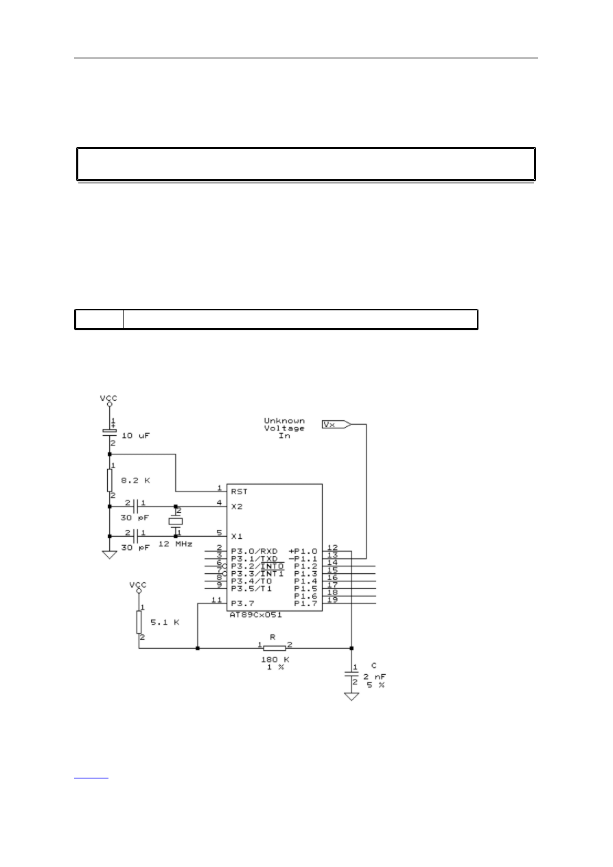
page -136-
© MCS Electronics, 1995-2006
channel=0 'input at P6.0
ref=0 'range from 0 to 5 Volt
b1=getad(channel,ref) 'place A/D into b1
GETAD2051
Action
Retrieves the analog value from a 89C2051 or 89C4051.
Syntax
var =
GETAD2051
()
Remarks
var
The variable that is assigned with the A/D value
The GETAD2051() function is only intended for the 89C2051 and 89C4051. It uses the analog
comparator of the chip.
Connect the hardware as following :
See also
GETAD

page -137-
© MCS Electronics, 1995-2006
Example
$regfile = "89c2051.dat"
Dim A As Byte
Do
A = Getad2051()
A = Lookup(a , Dta)
Print A
Loop
End
'this table converts the value into a packed BCD value
'this value can be used to diaplay the value on 2 7-segment displays
Dta:
Data 0 ' 0 0.000
Data 1 ' 1 0.047
Data 1 ' 2 0.093
Data 2 ' 3 0.138
Data 2 ' 4 0.184
Data 3 ' 5 0.229
Data 3 ' 6 0.273
Data 3 ' 7 0.317
Data 4 ' 8 0.361
Data 4 ' 9 0.404
Data 5 ' 10 0.447
Data 5 ' 11 0.489
Data 6 ' 12 0.531
Data 6 ' 13 0.573
Data 6 ' 14 0.614
Data 7 ' 15 0.655
Data 7 ' 16 0.696
Data 8 ' 17 0.736
Data 8 ' 18 0.776
Data 8 ' 19 0.815
Data 9 ' 20 0.854
Data 9 ' 21 0.893
Data &H10 ' 22 0.931
Data &H10 ' 23 0.969
Data &H10 ' 24 1.006
Data &H11 ' 25 1.044
Data &H11 ' 26 1.080
Data &H11 ' 27 1.117
Data &H12 ' 28 1.153
Data &H12 ' 29 1.189
Data &H12 ' 30 1.224

page -138-
© MCS Electronics, 1995-2006
Data &H13 ' 31 1.260
Data &H13 ' 32 1.295
Data &H13 ' 33 1.329
Data &H14 ' 34 1.363
Data &H14 ' 35 1.397
Data &H14 ' 36 1.431
Data &H15 ' 37 1.464
Data &H15 ' 38 1.497
Data &H15 ' 39 1.530
Data &H16 ' 40 1.562
Data &H16 ' 41 1.594
Data &H16 ' 42 1.626
Data &H17 ' 43 1.657
Data &H17 ' 44 1.688
Data &H17 ' 45 1.719
Data &H18 ' 46 1.750
Data &H18 ' 47 1.780
Data &H18 ' 48 1.810
Data &H19 ' 49 1.840
Data &H19 ' 50 1.869
Data &H19 ' 51 1.898
Data &H19 ' 52 1.927
Data &H20 ' 53 1.956
Data &H20 ' 54 1.984
Data &H20 ' 55 2.012
Data &H21 ' 56 2.040
Data &H21 ' 57 2.068
Data &H21 ' 58 2.095
Data &H21 ' 59 2.122
Data &H22 ' 60 2.149
Data &H22 ' 61 2.176
Data &H22 ' 62 2.202
Data &H22 ' 63 2.228
Data &H23 ' 64 2.254
Data &H23 ' 65 2.279
Data &H23 ' 66 2.305
Data &H23 ' 67 2.330
Data &H24 ' 68 2.355
Data &H24 ' 69 2.379
Data &H24 ' 70 2.404
Data &H24 ' 71 2.428
Data &H25 ' 72 2.452
Data &H25 ' 73 2.476
Data &H25 ' 74 2.499
Data &H25 ' 75 2.523

page -139-
© MCS Electronics, 1995-2006
Data &H26 ' 76 2.546
Data &H26 ' 77 2.569
Data &H26 ' 78 2.591
Data &H50 ' 79 5.000
Data &H49 ' 80 4.953
Data &H49 ' 81 4.907
Data &H48 ' 82 4.862
Data &H48 ' 83 4.816
Data &H47 ' 84 4.771
Data &H47 ' 85 4.727
Data &H47 ' 86 4.683
Data &H46 ' 87 4.639
Data &H46 ' 88 4.596
Data &H45 ' 89 4.553
Data &H45 ' 90 4.511
Data &H44 ' 91 4.469
Data &H44 ' 92 4.427
Data &H44 ' 93 4.386
Data &H43 ' 94 4.345
Data &H43 ' 95 4.304
Data &H42 ' 96 4.264
Data &H42 ' 97 4.224
Data &H42 ' 98 4.185
Data &H41 ' 99 4.146
Data &H41 ' 100 4.107
Data &H40 ' 101 4.069
Data &H40 ' 102 4.031
Data &H40 ' 103 3.994
Data &H39 ' 104 3.956
Data &H39 ' 105 3.920
Data &H39 ' 106 3.883
Data &H38 ' 107 3.847
Data &H38 ' 108 3.811
Data &H38 ' 109 3.776
Data &H37 ' 110 3.740
Data &H37 ' 111 3.705
Data &H37 ' 112 3.671
Data &H36 ' 113 3.637
Data &H36 ' 114 3.603
Data &H36 ' 115 3.569
Data &H35 ' 116 3.536
Data &H35 ' 117 3.503
Data &H35 ' 118 3.470
Data &H34 ' 119 3.438

page -140-
© MCS Electronics, 1995-2006
Data &H34 ' 120 3.406
Data &H34 ' 121 3.374
Data &H33 ' 122 3.343
Data &H33 ' 123 3.312
Data &H33 ' 124 3.281
Data &H32 ' 125 3.250
Data &H32 ' 126 3.220
Data &H32 ' 127 3.190
Data &H31 ' 128 3.160
Data &H31 ' 129 3.131
Data &H31 ' 130 3.102
Data &H31 ' 131 3.073
Data &H30 ' 132 3.044
Data &H30 ' 133 3.016
Data &H30 ' 134 2.988
Data &H29 ' 135 2.960
Data &H29 ' 136 2.932
Data &H29 ' 137 2.905
Data &H29 ' 138 2.878
Data &H28 ' 139 2.851
Data &H28 ' 140 2.824
Data &H28 ' 141 2.798
Data &H28 ' 142 2.772
Data &H27 ' 143 2.746
Data &H27 ' 144 2.721
Data &H27 ' 145 2.695
Data &H27 ' 146 2.670
Data &H26 ' 147 2.645
Data &H26 ' 148 2.621
Data &H26 ' 149 2.596
Data &H26 ' 150 2.572
Data &H25 ' 151 2.548
Data &H25 ' 152 2.524
Data &H25 ' 153 2.501
Data &H25 ' 154 2.477
Data &H24 ' 155 2.454
Data &H24 ' 156 2.431
Data &H24 ' 157 2.409
GETRC
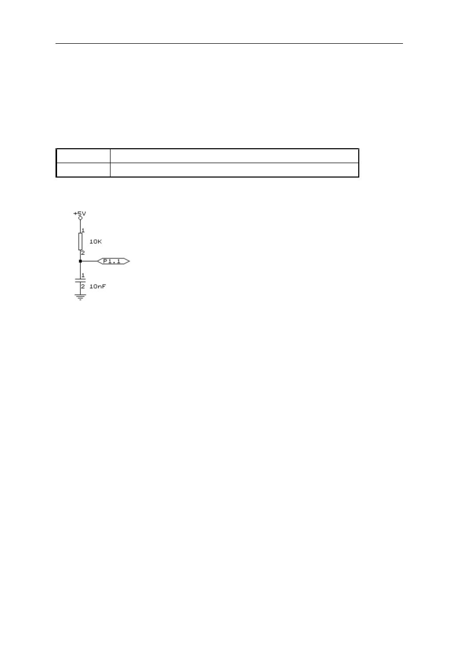
page -141-
© MCS Electronics, 1995-2006
Action
Retrieves the value of a resistor or a capacitor.
Syntax
var =
GETRC
( pin )
Remarks
var
The variable that receives the value.
pin
The port pin the R/C is connect to.
GETRC needs a resistor and capacitor in order to work. The capacitor is discharged and the
charging time will vary depending on the user resistor/capacitor value.
Uses
This function uses TIMER0.
See also
NONE
Example
'-----------------------------------------------------------------------
' GETRC.BAS
' Retrieve resistor value
' Connect 10KOhm variable resistor from +5V to P1.7 for this example
' Connect 10nF capacitor from P1.7 to ground
' The GETRC(pin) function measures the time needed to discharge the capacitor
'-----------------------------------------------------------------------
Config
Timer0
=
Timer
,
Gate
=
Internal
,
Mode
= 1
'the GETRC() functions needs timer 0
Config
Getrc = 10
'10mS wait for charging the
capacitor. This is the default so for 10 the CONFIG is not needed
$baud
= 9600
'just my settings
$crystal
= 11059200
Dim
W
As
Word
'allocate space for variable
Do
'forever
W = Getrc(
p1
.7)
'get RC value
W
'print it
Wait
1
'wait a moment
Loop

page -142-
© MCS Electronics, 1995-2006
'return values for cap=10nF .The resistor values where measured with a DVM
' 250 for 10K9
' 198 for 9K02
' 182 for 8K04
' 166 for 7K
' 154 for 6K02
' 138 for 5K04
' 122 for 4K04
' 106 for 3K06
' 86 for 2K16
' 54 for 1K00
' 22 for 198 ohm
' 18 for 150 ohm
' 10 for 104 ohm
' 6 for 1 ohm (minimum)
'As you can see there is a reasonable linearity
'So you can do some math to get the resistor value
'But the function is intended to serve as a rough indication for resistor values
'You can also change the capacitor to get larger values.
'With 10nF, the return value fits into a byte
GETRC5
Action
Retrieves a RC5 infrared code and sub address.
Syntax
GETRC5
(address , command)
Remarks
Address
The RC5 sub address received.
Command
The RC5 command received.
Use a Siemens infrared receiver SFH506-36 and connect it to port pin 3.2 to use this
c ommand.
This statement works together with the INT0 interrupt. See the example below on how to use
it.
In version 2.09 the command returns the toggle bit in bit position 5 of the address.
You can clear it like : address = address AND &B0001_1111
The toggle bit will toggle after each key press of the remote control.
page -143-
© MCS Electronics, 1995-2006
Example
'----------------------------------------------------------------------------
' RC5.BAS (c) 1995-2006 MCS Electronics
' connect SFH506-36 IR-receiver to PORT 3.2 (INT0)
' choose the correct port from the Compiler I2C TAB. Int0 should have P3.2 pin
' On other chips it may be another pin!
'----------------------------------------------------------------------------
Dim
New
As
Bit
Dim
Command
As
Byte
, Subaddress
As
Byte
Reset
Tcon
.0
'triggered by rising edge
On
Int0
Receiverc5
Enable
Int0
Enable
Interrupts
Do
If
New = 1
Then
'received new code
Disable
Int0
Command ;
" "
; Subaddress
New = 0
'reset new bit
Enable
Int0
End
If
Loop
Receiverc5:
'interrupt routine
'the getrc5 routine uses 30 bytes ! of the stack for measuring
'the interval between the bits
Getrc5
(Subaddress,command)
New = 1
'set flag
Return
GOSUB

page -144-
© MCS Electronics, 1995-2006
Action
Branch to and execute subroutine.
Syntax
GOSUB
label
Remarks
label
The name of the label where to branch to.
With GOSUB, your program jumps to the specified label, and continues execution at that
label.
When it encounters a RETURN statement, program execution will continue after the GOSUB
statement.
See also
Example
GOSUB Routine 'branch to routine
Print "Hello" 'after being at 'routine' print this
END 'terminate program
Routine: 'this is a subroutine
x = x + 2 'perform some math
PRINT X 'print result
RETURN 'return
GOTO
Action
Jump to the specified label.
Syntax
GOTO
label
Remarks
Labels can be up to 32 characters long.
When you use duplicate labels, the compiler will give you a warning.
See also
GOSUB

page -145-
© MCS Electronics, 1995-2006
Example
Dim
A
As
Byte
Start
:
'a label must end with a colon
A = A + 1
'increment a
If
A < 10
Then
'is it less than 10?
Goto
Start
'do it again
End
If
'close IF
" Ready"
'that is it
HEX
Action
Returns a string representation of a hexadecimal number.
Syntax
var =
HEX
( x )
Remarks
Var
A string variable.
X
A numeric variable such as Byte, Integer or Word.
See also
Example
Dim
A
As
Byte
, S
As
String
* 10
A = 123
S =
Hex
(a)
S
End
HEXVAL
Action
Convert string representing a hexadecimal number into a numeric variable.
Syntax
var =
HEXVAL
( x )

page -146-
© MCS Electronics, 1995-2006
Remarks
var
The numeric variable that must be assigned.
X
The hexadecimal string that must be converted.
var : Byte, Integer, Word, Long.
x : String.
The string that must be converted must have a length of 2 bytes ,4 bytes or 8 bytes, for
bytes, integers/words and longs respectively.
Difference with QB
In QB you can use the VAL() function to convert hexadecimal strings.
But since that would require an extra test for the leading &H signs, that are required in QB, a
separate function was designed.
See also
Example
Dim
A
As
Integer
, S
As
String
* 15
S =
"000A"
A =
Hexval
(s) :
A
'10
End
HIGH
Action
Retrieves the most significant byte of a variable.
Syntax
var =
HIGH
( s )
‘
high function gets the upper byte of a word
HIGH
(word) = byte
‘
high statement set the upper byte of a word
Remarks
Var
The variable that is assigned with the MSB of var S.
S
The source variable to get the MSB from.
Word
A word or integer variable that is assigned
Byte
The value to set to the MSB of the Word/Integer variable
The HIGH() function returns the MSB of a variable while the HIGH() statement sets the MSB
of a word variable.

page -147-
© MCS Electronics, 1995-2006
See also
Example
Dim I As Integer , Z As Byte
I = &H1001
Z = High(I) ' is 16
HIGHW
Action
Retrieves the two most significant bytes of a long.
Syntax
var =
HIGHW
( s )
Remarks
Var
The variable that is assigned with the two MSB of var S. It must
be an Integer or Word
S
The source variable to get the MSB from. Must be a long
See also
Example
Dim I As Long , Z As Word
I = &H10011001
Z = High(I)
HOME
Action
Place the cursor at the specified line at location 1.
Syntax
HOME
UPPER | LOWER | THIRD | FOURTH

page -148-
© MCS Electronics, 1995-2006
Remarks
If only HOME is used than, the cursor will be set to the upperline.
You can also specify the first letter of the line like: HOME U
See also
Example
Lowerline
LCD " Hello"
Home Upper
LCD " Upper"
I2CRECEIVE
Action
Receives data from an I2C serial device.
Syntax
I2CRECEIVE
slave, var
I2CRECEIVE
slave, var ,b2W, b2R
Remarks
slave
A byte, Word/Integer variable or constant with the slave address from the
I2C-device.
Var
A byte or integer/word variable that will receive the information from the
I2C-device.
b2W
The number of bytes to write.
Be cautious not to specify too many bytes!
b2R
The number of bytes to receive.
Be cautious not to specify too many bytes!
In BASCOM LT you could specify DATA for var, but since arrays are supported now you can
specify and array instead of DATA.
This command works only with some additional hardware. See appendix D.
See also
I2CSEND
Example
x = 0 'reset variable

page -149-
© MCS Electronics, 1995-2006
slave = &H40 'slave address of a PCF 8574 I/O IC
I2CRECEIVE slave, x 'get the value
PRINT x 'print it
Dim buf(10) as String
buf(1) = 1 : buf(2) = 2
I2CRECEIVE slave, buf(), 2, 1'send two bytes and receive one byte
Print buf(1) 'print the received byte
I2CSEND
Action
Send data to an I2C-device.
Syntax
I2CSEND
slave, var
I2CSEND
slave, var , bytes
Remarks
slave
The slave address off the I2C-device.
var
A byte, integer/word or number that holds the value which will be sent to
the I2C-device.
bytes
The number of bytes to send.
This command works only with additional hardware. See appendix D.
See also
I2CRECEIVE
Example
x = 5 'assign variable to 5
Dim ax(10) As Byte
slave = &H40 'slave address of a PCF 8574 I/O IC
bytes = 1 'send 1 byte
I2CSEND slave, x 'send the value or
For a = 1 to 10
ax(a) = a 'Fill dataspace
Next
bytes = 10
I2CSEND slave,ax(),bytes
END

page -150-
© MCS Electronics, 1995-2006
I2START,I2CSTOP, I2CRBYTE, I2CWBYTE
Action
I2CSTART generates an I2C start condition.
I2CSTOP generates an I2C stop condition.
I2CRBYTE receives one byte from an I2C-device.
I2CWBYTE sends one byte to an I2C-device.
Syntax
I2CSTART
I2CSTOP
I2CRBYTE
var, 8|9
I2CWBYTE
val
Remarks
var
A variable that receives the value from the I2C-device.
8/9
Specify 8 or ACK if there are more bytes to read. (ACK)
Specify 9 or NACK if it is the last byte to read. (NACK)
val
A variable or constant to write to the I2C-device.
This command works only with additional hardware. See
These functions are provided as an addition to the
See also
I2CRECEIVE
,
I2CSEND
Example
'----- Writing and reading a byte to an EEPROM 2404 -----------------
Dim
A
As
Byte
Const
Adresw = 174
'write of 2404
Const
Adresr = 175
'read adres of 2404
I2cstart
'generate start
I2cwbyte
Adresw
'send slaveadres
I2cwbyte
1
'send adres of EEPROM
I2cwbyte
3
'send a value
I2cstop
'generate stop
Waitms
10
'wait 10 mS because that is the time that the chip
needs to write the data
'----------now read the value back into the var a -------------------
I2cstart
'generate start
I2cwbyte
Adresw
'write slaveadres
I2cwbyte
1
'write adres of EEPROM to read
I2cstart
'generate repeated start
I2cwbyte
Adresr
'write slaveadres of EEPROM
I2crbyte
A , 9
'receive value into a. 9 means last byte to receive
I2cstop
'generate stop
A
'print received value

page -151-
© MCS Electronics, 1995-2006
End
IDLE
Action
Put the processor into the idle mode.
Syntax
IDLE
Remarks
In the idle mode, the system clock is removed from the CPU but not from the interrupt logic,
the serial port or the timers/counters.
The idle mode is terminated either when an interrupt is received or upon system reset
through the RESET pin.
See also
Example
IDLE
IF
Action
Allows conditional execution or branching, based on the evaluation of a Boolean expression.
Syntax
IF expression THEN
[ ELSEIF expression THEN ]
[ ELSE ]
END IF
Remarks
expression
Any expression that evaluates to true or false.
New is the ability to use the one line version of IF :
IF expression THEN statement [ ELSE statement ]

page -152-
© MCS Electronics, 1995-2006
The use of [ELSE] is optional.
Also new is the ability to test on bits :
IF var.bit = 1 THEN
In V 2.00 support for variable bit index is added:
Dim Idx as Byte
For IDX = 0 To 7
If P3.IDX = 1 Then
Print "1" ;
Else
Print "0" ;
End if
Next
A new feature in V2 is the ability to use multiple tests:
If a > 10 AND A < 10 OR A = 15 Then
NOP
End if
It does not work with strings but only numeric conditions.
When you want to test on bytes you can also use the string representation:
Dim X As Byte
If X = "A" then ' normally you need to write :
If X = 65 Then 'so these two lines do the same thing
See also
Example
Dim
A
As
Integer
A = 10
If
A = 10
Then
'test expression
" This part is executed."
'this will be printed
Else
" This will never be executed."
'this not
End
If
If
A = 10
Then
"New in BASCOM"
If
A = 10
Then
Goto
Label1
Else
"A<>10"
Label1:
Rem The following example shows enhanced use of IF THEN
If
A.15 = 1
Then
'test for bit
"BIT 15 IS SET"
End
If
REM the following example shows the 1 line use of IF THEN [ELSE]
If
A.15 = 0
Then
"BIT 15 is cleared"
Else
"BIT 15 is set"
INCR
Action

page -153-
© MCS Electronics, 1995-2006
Increments a variable by one.
Syntax
INCR
var
Remarks
Var
Any numeric variable.
There are often situations where you want a number to be increased by 1.
The INCR statement is faster then var = var + 1.
See also
DECR
Example
Dim
A
As
Integer
Do
'start loop
Incr
A
'increment a by 1
A
'print a
Loop
Until
A > 10
'repeat until a is greater than 10
INKEY
Action
Returns the ASCII value of the first character in the serial input buffer.
Syntax
var =
INKEY
()
var =
INKEY
(#channel)
Remarks
Var
Byte, Integer, Word, Long or String variable.
Channel
The channel number of device
If there is no character waiting, a zero will be returned.
The INKEY routine can be used when you have a RS-232 interface on your uP.
See the manual for a design of an RS-232 interface.
The RS-232 interface can be connected to a comport of your computer.
The INKEY() function only works with the hardware UART, not the software UART.

page -154-
© MCS Electronics, 1995-2006
See also
Example
Dim
A
As
Byte
Do
'start loop
A =
Inkey
()
'look for character
If
A > 0
Then
'is variable > 0?
A
'yes , there was a character in the buffer
'so print it
End
If
Loop
'loop forever
Example
$regfile
=
"80517.dat"
Open
"COM2:"
For
Binary
As
#1
'open serial channel 1 on 80537
Dim
St
As
Byte
St =
Inkey
(#1)
'get key from com2
If
St > 0
Then
Printbin
#1 , St
'send to com 2
End
If
Close
#1
INP
Action
Returns a byte read from a hardware port or external memory location.
Syntax
var =
INP
(address)
Remarks
var
Numeric variable that receives the value.
address
The address where to read the value from.
The INP statement only works on systems with an uP that can address external
memory.
See also
OUT
,
PEEK
,
POKE
Example

page -155-
© MCS Electronics, 1995-2006
Dim a As Byte
a = INP(&H8000) 'read value that is placed on databus(d0-d7) at
'hex address 8000
PRINT a
END
INPUT
Action
Allows input from the keyboard during program execution.
Syntax
INPUT
[" prompt" ] , var [ , varn ] [ NOECHO ] [ TIMEOUT = xx]
Remarks
Prompt
An optional string constant printed before the prompt character.
Var,varn
A variable to accept the input value or a string.
NOECHO
Disables input echoed back to the Comport.
TIMEOUT
Optional delay time. When you specify the delay time, the routine will
return when no input data is available after the specified time. No timer is
used but a long is used to count down.
The INPUT routine can be used when you have a RS-232 interface on your uP.
See the manual for a design of a RS-232 interface.
The RS-232 interface can be connected to a serial communication port of your computer.
This way you can use a terminal emulator and the keyboard as an input device.
You can also use the built in terminal emulator. A backspace will remove the last entered
character.
Difference with QB
In QB you can specify &H with INPUT so QB will recognize that a hexadecimal string is used.
BASCOM implements a new statement: INPUTHEX.
See also
Example
'--------------------------------------------------------------
' (c) 1995-2006 MCS Electronics
'--------------------------------------------------------------
' file: INPUT.BAS
' demo: INPUT, INPUTHEX
'--------------------------------------------------------------
'To use another baudrate and crystalfrequency use the
'metastatements $BAUD = and $CRYSTAL =
$baud
= 1200
'try 1200 baud for example
$crystal
= 12000000
'12 MHz

page -156-
© MCS Electronics, 1995-2006
'---------------------------------------------------------------
' When you need that the program times out on waiting for a character
' you need to use the TIMEOUT option.
' When the charcter is not received within the specified time ERR will be set to 1
' otherwise ERR will be 0.
' IMPORTANT : the TIMEOUT variable will use 4 bytes of internal memory
'---------------------------------------------------------------
Dim
V
As
Byte
, B1
As
Byte
Dim
C
As
Integer
, D
As
Byte
Dim
S
As
String
* 15
'only for uP with XRAM support
Input
"Use this to ask a question "
, V
Input
B1
'leave out for no question
Input
"Enter integer "
, C
C
Inputhex
"Enter hex number (4 bytes) "
, C
C
Inputhex
"Enter hex byte (2 bytes) "
, D
D
Input
"More variables "
, C , D
C ;
" "
; D
Input
C
Noecho
'supress echo
Input
"Enter your name "
, S
"Hello "
; S
Input
S
Noecho
'without echo
S
'unremark next line and remark all lines above for the TIMEOUT option
'this because when you use TIMEOUT once, you need to use it for all INPUT statements
'Input "Name " , S Timeout = 0
'Print Err ; " " ; s
End
INPUTBIN
Action
Read binary values from the serial port.
Syntax
INPUTBIN
var1 [,var2]
INPUTBIN
#dev, var1 [,var2]
Remarks

page -157-
© MCS Electronics, 1995-2006
var1
The variable that is assigned with the characters from the serial port.
var2
An optional second (or more) variable that is assigned with the characters from
the serial.
#dev
Device number. For use with OPEN and CLOSE. Dev is the device number.
The number of bytes to read is depending from the variable you use.
When you use a byte variable, 1 character is read from the serial port.
An integer will wait for 2 characters and an array will wait wait until the whole array is filled.
Note that the INPUTBIN statement doesn't wait for a <RETURN> but just for the number of
bytes.
See also
Example
Dim a as Byte, C as Integer
INPUTBIN a, c 'wait for 3 characters
End
'This code only for 80517 and 80537 with dual serial port
Open "COM2:" For Binary As #1 'open serial channel 1
INPUTBIN #1, a
Close #1
INPUTHEX
Action
Allows input from the keyboard during program execution.
Syntax
INPUTHEX
[" prompt" ] , var [ , varn ] [ NOECHO ] [TIMEOUT=xx]
Remarks
prompt
An optional string constant printed before the prompt character.
Var,varn
A numeric variable to accept the input value.
NOECHO
Disables input echoed back to the Comport.
TIMEOUT
Optional delay time. When you specify the delay time, the routine will
return when no input data is available after the specified time. No timer is
used but 4 bytes are taken from the internal memory to provide a count
down timer.
When you use the TIMEOUT option once, you must use it for all INPUT/INPUTHEX statements.
Providing zero as the timeout parameter will wait for the longest possible time.
The INPUTHEX routine can be used when you have a RS-232 interface on your uP.

page -158-
© MCS Electronics, 1995-2006
See the manual for a design of a RS-232 interface.
The RS-232 interface can be connected to a serial communication port of your computer.
This way you can use a terminal emulator and the keyboard as input device.
You can also use the build in terminal emulator.
If var is a byte then the input must be 2 characters long.
If var is an integer/word then the input must be 4 characters long.
If var is a long then the input must be 8 characters long.
Difference with QB
In QB you can specify &H with INPUT so QB will recognize that a hexadecimal string is used.
BASCOM implement a new statement : INPUTHEX.
See also
Example
Dim x As Byte
INPUTHEX " Enter a number " , x 'ask for input
INSTR
Action
Returns the position of a sub string in a string.
Syntax
var =
INSTR
( start , string , substr )
var =
INSTR
( string , substr )
Remarks
Var
Numeric variable that will be assigned with the position of the
sub string in the string. Returns 0 when the sub string is not
found.
Start
An optional numeric parameter that can be assigned with the first
position where must be searched in the string. By default (when
not used) the whole string is searched starting from position 1.
String
The string to search.
Substr
The search string.
At the moment INSTR() works only with internal strings.
Support for external strings will be added too.
Difference with QB
No constants can be used for the string and sub string.

page -159-
© MCS Electronics, 1995-2006
See also
None
Example
Dim
S
As
String
* 10 , Z
As
String
* 5
Dim
Bp
As
Byte
S =
"This is a test"
Z =
"is"
Bp =
Instr
(s , Z) :
Bp
'should print 3
Bp =
Instr
(4 , S , Z) :
Bp
'should print 6
End
LCASE
Action
Converts a string into lower or upper case.
Syntax
dest =
LCASE
( source )
Remarks
dest
The string variable that will be assigned with the lower case of string
SOURCE.
source
The source string. The original string will be unchanged.
See also
Example
Dim
S
As
String
* 12 , Z
As
String
* 12
Input
"Hello "
, S
'assign string
S =
Lcase
(s)
'convert to lowercase
S
'print string
S =
Ucase
(s)
'convert to upper case
S
'print string
LCD

page -160-
© MCS Electronics, 1995-2006
Action
Send constant or variable to LCD display.
Syntax
LCD
x
Remarks
X
Variable or constant to display.
More variables can be displayed separated by the ; -sign
LCD a ; b1 ; " constant"
The LCD statement behaves just like the PRINT statement.
See also
Example
'--------------------------------------------------------------
' (c) 1995-2006 MCS Electronics
'--------------------------------------------------------------
' file: LCD.BAS
' demo: LCD, CLS, LOWERLINE, SHIFTLCD, SHIFTCURSOR, HOME
' CURSOR, DISPLAY
'--------------------------------------------------------------
$sim
Rem The $sim statement will remove long delays for the simulator
Rem It is important to remove this statement when compiling the final file
'Config Lcdpin = Pin , Db4 = P3.1 , Db5 = P3.2 , Db6 = P3.3 , Db7 = P3.4 , E = P3.5 , Rs = P3.6
Rem with the config lcdpin statement you can override the compiler settings
Dim
A
As
Byte
Config
Lcd
= 16 * 2
'configure lcd screen
'other options are 16 * 4 and 20 * 4, 20 * 2 , 16 * 1a
'When you dont include this option 16 * 2 is assumed
'16 * 1a is intended for 16 character displays with split addresses over 2 lines
'$LCD = address will turn LCD into 8-bit databus mode
' use this with uP with external RAM and/or ROM
' because it doesnt need the port pins !
Cls
'clear the LCD display
Lcd
"Hello world."
'display this at the top line
Wait
1
Lowerline
'select the lower line
Wait
1
Lcd
"Shift this."
'display this at the lower line
Wait
1
For
A = 1
To
10
Shiftlcd
Right
'shift the text to the right
Wait
1
'wait a moment
Next

page -161-
© MCS Electronics, 1995-2006
For
A = 1
To
10
Shiftlcd
Left
'shift the text to the left
Wait
1
'wait a moment
Next
Locate
2 , 1
'set cursor position
Lcd
"*"
'display this
Wait
1
'wait a moment
Shiftcursor
Right
'shift the cursor
Lcd
"@"
'display this
Wait
1
'wait a moment
Home
Upper
'select line 1 and return home
Lcd
"Replaced."
'replace the text
Wait
1
'wait a moment
Cursor
Off
Noblink
'hide cursor
Wait
1
'wait a moment
Cursor
On
Blink
'show cursor
Wait
1
'wait a moment
Display
Off
'turn display off
Wait
1
'wait a moment
Display
On
'turn display on
'-----------------NEW support for 4-line LCD------
Thirdline
Lcd
"Line 3"
Fourthline
Lcd
"Line 4"
Home
Third
'goto home on line three
Home
Fourth
Home
F
'first letteer also works
Locate
4 , 1 :
Lcd
"Line 4"
Wait
1
'Now lets build a special character
'the first number is the characternumber (0-7)
'The other numbers are the rowvalues
'Use the LCD tool to insert this line
Deflcdchar
0 , 31 , 17 , 17 , 17 , 17 , 17 , 31 , 0
' replace ? with number (0-7)
Deflcdchar
1 , 16 , 16 , 16 , 16 , 16 , 16 , 16 , 31
' replace ? with number (0-7)
Cls
'select data RAM
Rem it is important that a CLS is following the deflcdchar statements because it will set the
controller back in datamode
Lcd
Chr
(0) ;
Chr
(1)
'print the special character
'----------------- Now use an internal routine ------------
Acc
= 1
'value into ACC
Call
Write_lcd
'put it on LCD
End
LCDINIT
Action
Reinitialize the LCD display.

page -162-
© MCS Electronics, 1995-2006
Syntax
LCDINIT
Remarks
When you use any of the LCD display routines the LCD display will be initialized
automatic at startup of your program.
The LCD routines demand that the WR of the LCD display is connected to GND.
When in your design the WR pin of the LCD is connected to a PIN of the micro
processor, it will be high during the initialization and so the display will not be
initialized properly.
The LCDINIT routine allows you to perform initialization after you have set the
pin that controls WR of the LCD to 0V.
See also
Example
'--------------------------------------------------------------
' (c) 1995-2006 MCS Electronics
'--------------------------------------------------------------
' file: LCD.BAS
' demo: LCD, CLS, LOWERLINE, SHIFTLCD, SHIFTCURSOR, HOME
' CURSOR, DISPLAY
'--------------------------------------------------------------
$sim
Rem The $sim statement will remove long delays for the simulator
Rem It is important to remove this statement when compiling the final file
'Config Lcdpin = Pin , Db4 = P3.1 , Db5 = P3.2 , Db6 = P3.3 , Db7 = P3.4 , E = P3.5 , Rs = P3.6
Rem with the config lcdpin statement you can override the compiler settings
Dim
A
As
Byte
Config
Lcd
= 16 * 2
'configure lcd screen
'other options are 16 * 4 and 20 * 4, 20 * 2 , 16 * 1a
'When you dont include this option 16 * 2 is assumed
'16 * 1a is intended for 16 character displays with split addresses over 2 lines
'$LCD = address will turn LCD into 8-bit databus mode
' use this with uP with external RAM and/or ROM
' because it doesnt need the port pins !
'----------------- these 2 lines can be used when WR is connected to P1.0 for example ---
P1.0 = 0
INITLCD
'-----------------------------------------------------------------------------------------
Cls
'clear the LCD display
Lcd
"Hello world."
'display this at the top line
Wait
1
Lowerline
'select the lower line
Wait
1
Lcd
"Shift this."
'display this at the lower line

page -163-
© MCS Electronics, 1995-2006
LCDHEX
Action
Send variable in hexadecimal format to the LCD display.
Syntax
LCDHEX
var
Remarks
var
Variable to display.
var1 : Byte, Integer, Word, Long, Single, Constant.
The same rules apply as for
See also
Example
Dim a as byte
a = 255
LCD a
Lowerline
LCDHEX a
End
LEFT
Action
Return the specified number of leftmost characters in a string.
Syntax
var =
LEFT
(var1 , n )
Remarks
var
The string that is assigned.
Var1
The sourcestring.
n
The number of characters to get from the sourcestring.

page -164-
© MCS Electronics, 1995-2006
n : Byte, Integer, Word, Long, Constant.
For string operations, all the strings must be of the same type : internal or external.
See Also
Example
Dim
S
As
Xram
String
* 15 , Z
As
Xram
String
* 15
S =
"ABCDEFG"
Z =
Left
(s , 5)
Z
'ABCDE
End
LEN
Action
Returns the length of a string.
Syntax
var =
LEN
( string )
Remarks
var
A numeric variable that is assigned with the length of string.
string
The string to calculate the length of.
Example
Dim S As String * 12
Dim A As Byte
S = "test"
A = Len(s)
Print A ' prints 4
LOAD
Action
Load specified TIMER with a value for auto reload mode.
Syntax
LOAD
TIMER , value

page -165-
© MCS Electronics, 1995-2006
Remarks
TIMER
TIMER0, TIMER1 or TIMER2.
Value
The variable or value to load.
When you use the ON TIMERx statement with the TIMER/COUNTER in mode 2,
you can specify on which interval the interrupt must occur.
The value can range from 1 to 255 for TIMER0 and TIMER1.
For TIMER2 the range is 1-65535.
The LOAD statement calculates the correct reload value out of the parameter.
The formula : TLx = THx = (256-value)
For TIMER2 : RCAP2L = RCAP2H = (65536 - value)
The load statement is not intended to assign/read a value to/from the timers/counters. Use
See
for more details
Example
LOAD TIMER0, 100 'load TIMER0 with 100
Will generate :
Mov tl0,#h'9C
Mov th0,#h'9C
LOAD TIMER2, 1000
Will generate:
Mov RCAP2L,#24
Mov RCAP2H,#252
LOCATE
Action
Moves the LCD cursor to the specified position.
Syntax
LOCATE
y , x
Remarks
X
Constant or variable with the position. (1-64*)
Y
Constant or variable with the line (1 - 4*)
* depending on the used display
For Graphical displays X can be in the range from 1-30 and y in the range from 1-8.

page -166-
© MCS Electronics, 1995-2006
See also
Example
LCD "Hello"
Locate 1,10
LCD "*"
LOOKUP
Action
Returns a value from a table.
Syntax
var
=
LOOKUP
(
value
, label )
Remarks
var
The returned value
value
A value with the index of the table
label
The label where the data starts
var : Byte, Integer, Word, Long, Single.
value : Byte, Integer, Word, Long, Constant.
See also
Example
Dim
B1
As
Byte
, I
As
Integer
B1 =
Lookup
(1 , Dta)
B1
' Prints 2 (zero based)
I =
Lookup
(0 , Dta2)
End
Dta:
Data
1 , 2 , 3 , 4 , 5
Dta2:
'integer data
Data
1000% , 2000%
page -167-
© MCS Electronics, 1995-2006
LOOKUPSTR
Action
Returns a string from a table.
Syntax
var
=LOOKUPSTR(
value
, label [, language , length])
Remarks
var
The string returned
value
A value with the index of the table. The index is zero-based. That is, 0 will
return the first element of the table.
label
The label where the data starts
language
An optional variable that holds a number to identify the language. The first
language starts with the number 0.
length
The length of the data for each language.
value : Byte, Integer, Word, Long, Constant. Range(0-255)
See also
Example
Dim
S
As
String
* 8 , Idx
As
Byte
Idx = 0 : S =
Lookupstr
(idx , Sdata)
S
'will print 'This'
End
Sdata:
Data
"This"
,
"is"
,
"a test"
Example 2
Dim
S
As
String
* 8 , Idx
As
Byte
, Language
As
Byte
Idx = 0 : Language = 1
S =
Lookupstr
(idx , Sdata , Language , 17)
S
' will print 'Dit '
End
Sdata:
Data
"This"
,
"is"
,
"a test "
'
each language data must have the same length
Data
"Dit "
,
"is"
,
"een test"
'the length is 17 because strings include a 0 byte
LOW

page -168-
© MCS Electronics, 1995-2006
Action
Retrieves the least significant byte of a variable.
Syntax
var =
LOW
( s )
Remarks
Var
The variable that is assigned with the LSB of var S.
S
The source variable to get the LSB from.
See also
Example
Dim I As Integer , Z As Byte
I = &H1001
Z = Low(I) ' is 1
LOWW
Action
Retrieves the two least significant bytes of a long.
Syntax
var =
LOWW
( s )
Remarks
var
The variable that is assigned with the two LSB of var S.
s
The source variable to get the LSB's from.
See also
HIGHW
,
HIGH
,
LOW
Example
Dim L As Integer , Z As Long
L = &H1001
Z = LowW(L)
LOWERLINE

page -169-
© MCS Electronics, 1995-2006
Action
Reset the LCD cursor to the lowerline.
Syntax
LOWERLINE
Remarks
None
See also
Example
LCD "Test"
LOWERLINE
LCD "Hello"
End
MAKEBCD
Action
Convert a variable into its BCD value.
Syntax
var1 =
MAKEBCD
(var2)
Remarks
var1
Variable that will be assigned with the converted value.
Var2
Variable that holds the decimal value.
When you want to use an I2C clock device, which stores its values as BCD values you can use
this function to convert variables from decimal to BCD.
For printing the bcd value of a variable, you can use the BCD() function.
See also
MAKEDEC
,
BCD()
Example
Dim a As Byte
a = 65
LCD a
Lowerline

page -170-
© MCS Electronics, 1995-2006
LCD BCD(a)
a = MakeBCD(a)
LCD " " ; a
End
MAKEDEC
Action
Convert a BCD byte or Integer/Word variable to its DECIMAL value.
Syntax
var1 =
MAKEDEC
(var2)
Remarks
var1
Variable that will be assigned with the converted value.
var2
Variable that holds the BCD value.
When you want to use an I2C clock device which stores its values as BCD values you can use
this function to convert variables from BCD to decimal.
See also
Example
Dim a As Byte
a = 65
LCD a
Lowerline
LCD BCD(a)
a = MakeDEC(a)
LCD " " ; a
End
MAKEINT
Action
Compacts 2 bytes into a word or integer.
Syntax
varn =
MAKEINT
(LSB , MSB)

page -171-
© MCS Electronics, 1995-2006
Remarks
Varn
Variable that will be assigned with the converted value.
LSB
Variable or constant with the Least Significant Byte.
MSB
Variable or constant with the Most Significant Byte.
The equivalent code is :
varn = (256 * MSB) + LSB
See also
Example
Dim a As Integer , I As Integer
a = 2
I = MakeINT(a , 1) 'I = (1 * 256) + 2 = 258
End
MAX
Action
Returns the highest value of an array.
Syntax
var =
MAX
( ar(1) )
Remarks
Var
Numeric variable that will be assigned with the highest value of the
array.
ar()
The first array element of the array to return the highest value of.
At the moment MAX() works only with BYTE arrays.
Support for other data types will be added too.
See also
MIN
,
AVG
Example
Dim ar(10) As Byte
Dim bP as Byte
For bP = 1 to 10
ar(bP) = bP
Next
bP = Max(ar(1))
Print bP 'should print 10

page -172-
© MCS Electronics, 1995-2006
End
MID
Action
The MID function returns part of a string (a sub string).
The MID statement replaces part of a string variable with another string.
Syntax
var =
MID
(var1 ,st [, l] )
MID
(var ,st [, l] ) = var1
Remarks
Var
The string that is assigned.
Var1
The source string.
St
The starting position.
L
The number of characters to get/set.
Operations on strings require that all strings are of the same type(internal or external)
See also
Example
Dim
S
As
Xram
String
* 15 , Z
As
Xram
String
* 15
S =
"ABCDEFG"
Z =
Mid
(s , 2 , 3)
Z
'BCD
Z =
"12345"
Mid
(s , 2 , 2) = Z
S
'A12DEFG
End
MIN
Action
Returns the lowest value of an array.
Syntax
var =
MIN
( ar(1) )

page -173-
© MCS Electronics, 1995-2006
Remarks
Var
Numeric variable that will be assigned with the lowest value of the
array.
ar()
The first array element of the array to return the lowest value of.
At the moment MIN() works only with BYTE arrays.
Support for other data types will be added too.
See also
Example
Dim ar(10) As Byte
Dim bP as Byte
For bP = 1 to 10
ar(bP) = bP
Next
bP = Min(ar(1))
Print bP 'should print 1
End
MOD
Action
Returns the remainder of a division.
Syntax
ret = var1
MOD
var2
Remarks
Ret
The variable that receives the remainder.
var1
The variable to divide.
var2
The divisor.
Example
a = 10 MOD 3 'divide 10 through 3
PRINT a 'print remainder (1)
MWINIT
Action
Initializes the pins in order to use them with the micro wire statements.

page -174-
© MCS Electronics, 1995-2006
Syntax
MWINIT
See also
MWREAD
Action
Read a value from the micro wire bus.
Syntax
MWREAD
variable , opcode , address, bytes
Remarks
Variable
The variable that is assigned with the value retrieved from the
micro wire bus.
Opcode
The opcode to use.
Address
The address of the device.
Bytes
Number of bytes to send.
See also
Example
'-----------------------------------------------------------------
' MicroWire test file
' please read microwire specs for understanding microwire
'-----------------------------------------------------------------
'CS - chip select
'DIN - data in
'DOUT - data Out
'CLOCK- Clock
'AL - address lines
' 93C46 93C56 93C57 93C66
'----------------------------------------------------------------------------
' Data bits: 8 16 8 16 8 16 8 16
' AL : 7 6 9 8 8 7 9 8
'you could use the same pin for DIN and DOUT
'we use a 93C46 and send bytes not words so AL is 7
Config Microwire = Pin , Cs = P1.1 , Din = P1.2 , Dout = P1.4 , Clock = P1.5 , Al = 7

page -175-
© MCS Electronics, 1995-2006
'init pins
Mwinit
'dimension variable used
Dim X As Byte
'enable write to eeprom
'send startbit, opcode (00) and 11 + address
'Mwwopcode opcode, numberOfBits
Mwwopcode &B1001100000 , 10
'the mwwopcode can send a command(opcode) to a device
X = 10
'write value of X to address 0
'opcode is 01
'we write 1 byte
'Mwwrite var,opcode,address,numberOfBytes
Mwwrite X , &B101 , 0 , 1
Waitms 10
X = 0
'read back
' mwread var,opcode,address,numberofbytes
Mwread X , &B110 , 0 , 1
'disable write
'send startbit, opcode (00) and 00 + address
Mwwopcode &B1000000000 , 10
End
MWWOPCODE
Action
Write an opcode to a micro wire device.
Syntax
MWWOPCODE
opcode , bits
Remarks
Opcode
The opcode that needs to be send to the micrwire device.
See the microwire docs for the right values.
Bits
The number of bits to send.
Before you can work with microwire you must send an opcode to enable writing an EEPROM
for example.
See also
MWINIT
,
MWWRITE
,
MWREAD

page -176-
© MCS Electronics, 1995-2006
Example
'enable write to EEPROM
'Needed bits : startbit (1), opcode (00) and (11) + address
'Mwwopcode opcode, numberOfBits
Mwwopcode &B1001100000 , 10 'send the code
MWWRITE
Action
Writes a value to the micro wire bus.
Syntax
MWWRITE
variable , opcode , address, bytes
Remarks
Variable
The variable whos content must be send to the micro wires device.
Opcode
The opcode to use.
Address
The address of the device.
Bytes
Number of bytes to send.
See also
MWINIT
,
MWREAD
,
MWWOPCODE
Example
'write value of X to address 0
'opcode is 01 and we write one byte
Mwwrite X , &B101 , 0 , 1
NEXT
Action
Ends a FOR..NEXT structure.
Syntax
NEXT
[var]
Remarks
Var
The index variable that is used as a counter when you form the
structure with FOR var. Var is optional and not needed.

page -177-
© MCS Electronics, 1995-2006
You must end each FOR statement with a NEXT statement.
See also
Example
Dim
X
As
Byte
, Y
As
Byte
, A
As
Byte
Y = 10
'make y 10
For
A = 1
To
10
'do this 10 times
For
X = Y
To
1
'this one also
X ; A
'print the values
Next
'next x (count down)
Next
A
'next a (count up) END
ON Interrupt
Action
Execute subroutine when specified interrupt occurs.
Syntax
ON
interrupt label [NOSAVE]
Remarks
interrupt
INT0, INT1, SERIAL, TIMER0 ,TIMER1 or TIMER2.
Chip specific interrupts can be found under microprocessor support.
Label
The label to jump to if the interrupt occurs.
NOSAVE
When you specify NOSAVE, no registers are saved and restored in the
interrupt routine. So when you use this option be sure to save and
restore used registers.
You must return from the interrupt routine with the RETURN statement.
You may have only one RETURN statement in your interrupt routine because the compiler
restores the registers and generates a RETI instruction when it encounters a RETURN
statement in the ISR.
You can't use TIMER1 when you are using SERIAL routines such as PRINT
because TIMER1 is used as a BAUDRATE generator.
When you use the INT0 or INT1 interrupt you can specify on which condition the interrupt
must be triggered.
You can use the Set/Reset statement in combination with the TCON-register for this purpose.
SET TCON.0 : trigger INT0 by falling edge.
RESET TCON.0 : trigger INT0 by low level.
SET TCON.2 : trigger INT1 by falling edge.

page -178-
© MCS Electronics, 1995-2006
RESET TCON.2 : trigger INT1 by low level.
See
for more details
See Also
Example
ENABLE INTERRUPTS
ENABLE INT0 'enable the interrupt
ON INT0 Label2 nosave 'jump to label2 on INT0
DO 'endless loop
LOOP
END
Label2:
PRINT " A hardware interrupt occurred!" 'print message
RETURN
ON Value
Action
Branch to one of several specified labels, depending on the value of a variable.
Syntax
ON
var [GOTO] [GOSUB] label1 [, label2 ]
Remarks
Var
The numeric variable to test.
This can also be a SFR such as P1.
label1, label2
The labels to jump to depending on the value of var.
Note that the value is zero based. So when var = 0, the first specified label is
jumped/branched.
See Also
ON interrupt
Example
Dim
X
As
Byte
X = 2
'assign a variable interrupt
On
X
Gosub
Lbl1 , Lbl2 , Lbl3
'jump to label lbl3
X = 0
On
X
Goto
Lbl1 , Lbl2 , Lbl3
End

page -179-
© MCS Electronics, 1995-2006
Lbl3:
"lbl3"
Return
Lbl1:
nop
Lbl2:
nop
'nop is an ASM statement that does nothing
OPEN - CLOSE
Action
Opens and closes a device.
Syntax
OPEN
"device" for MODE As #channel
CLOSE
#channel
Remarks
Device
There are 2 hardware devices supported: COM1 and COM2.
With the software UART, you must specify the port pin and the baud rate.
COM3.0:9600 will use PORT 3.0 at 9600 baud.
Optional is ,INVERTED this will use inverted logic so you don't need MAX232
inverters.
MODE
You can use BINARY, INPUT or OUTPUT for COM1 and COM2, but for the
software UART pins, you must specify INPUT or OUTPUT.
Channel
The number of the channel to open. Must be a positive constant.
Since there are uP's such as the 80537 with 2 serial channels on board, the compiler must
know which serial port you want to use. That is why the OPEN statement is implemented.
With only 1 serial port on board, you don't need this statement.
The statements that support the device are
,
PRINTHEX
,
INPUT
and
INPUTHEX
.
Every opened device must be closed using the CLOSE #channel statement. Of course you
must use the same channel number.
The software UART, only supports the
GET
and
PUT
statements to retrieve and send data and
the
PRINTBIN
and
INPUTBIN
statement.
The SW UART uses timed loops and interrupts can slow down these loops. So turn interrupts
off before you use the SW UART.
COM1: and COM2: are hardware ports, and can be used with PRINT etc.
For the software UART it is important that the pin you use is bit addressable. In most cases a
PORT is bit addressable but some chips have ports that are not bit addressable. When you
use such a port you will get errors like : Error 208, bit variable not found.

page -180-
© MCS Electronics, 1995-2006
Since the OPEN statement doesn't use real file handles like DOS but only serves as a compiler
directive, it is important that you must use the CLOSE statement as the last statement in
your program.
The following example shows when it will NOT WORK :
OPEN "COM2:" FOR BINARY AS #1 'open the port
PRINT #1, "Hello" 'print to serial 1
Gosub Test
PRINT "Hello" 'print to serial 0
CLOSE #1
Test:
Print #1, "test"
Return
Since the compiler frees the handle when it encounters the CLOSE statement, the PRINT #1,
"test" code is never executed. To solve this you should put the CLOSE #1 statement under
the Return statement.
OPEN "COM2:" FOR BINARY AS #1 'open the port
PRINT #1, "Hello" 'print to serial 1
Gosub Test
PRINT "Hello" 'print to serial 0
Test:
Print #1, "test"
Return
Close #1
See also
GET
,
PUT
Example 1
'only works with a 80517 or 80537
CONFIG BAUD1 = 9600 'serial 1 baudrate
OPEN "COM2:" FOR BINARY AS #1 'open the port
PRINT #1, "Hello" 'print to serial 1
PRINT "Hello" 'print to serial 0
CLOSE #1 'close the channel
Example 2
'works with every port pin
Dim A As Byte , S As String * 16 , I As Byte , Dum As Byte
'a software comport is named after the pin you use
'for example P3.0 will be "COM3.0:" (so there is no P)
'for software comports, you must provide the baudrate
'So for 9600 baud, the devicename is "COM3.0:9600"
'When you want to use the pin for sending, you must open the device for OUTPUT
'When you want to use the pin for receiving, you must open the device for INPUT
'At this time only variables can be sent and received with the PUT and GET statements.
'In the feature PRINT etc. will support these software comports.

page -181-
© MCS Electronics, 1995-2006
Open "com3.1:9600" For Output As #1 'p3.1 is normally used for tx so testing is easy
Open "com3.0:9600,INVERTED" For Input As #2 'p3.0 is normally used for RX so testing
is easy
S = "test this" 'assign string
Dum = Len(s) 'get length of string
For I = 1 To Dum 'for all characters from left to right
A = Mid(s , I , 1) 'get character
Put #1 , A 'write it to comport
Next
Do
Get #2 , A 'get character from comport
Put #1 , A 'write it back
Print A 'use normal channel
Loop
Close #1 ' finally close device
Close #2
End
OUT
Action
Sends a byte to a hardware port or external memory address.
Syntax
OUT
address, value
Remarks
address
The address where to send the byte to.
value
The variable or value to send.
The OUT statement only works on systems with a uP that can address external
memory.
See also
INP
,
PEEK
,
POKE
Example
Dim a as byte
OUT &H8000,1 'send 1 to the databus(d0-d7) at hex address 8000
END
Will generate :
Mov A,#1
Mov dptr,#h'8000

page -182-
© MCS Electronics, 1995-2006
Movx @dptr,a
P1,P3
Action
P1 and P3 are special function registers that are treated as variables.
Syntax
Px = var
var = Px
Remarks
X
The number of the port. (1 or 3). P3.6 can't be used with an
AT89C2051!
Var
The variable to retrieve or to set.
Note that other processors can have more ports such as P0, P2, P4 etc.
When you select the proper .DAT file you can also use these ports as variables.
In fact you can use any SFR as a byte variable in BASCOM.
ACC = 0 'will reset the accumulator for example
See
hardware
for a more detailed description of the ports.
Example
Dim
A
As
Byte
, B1
As
Bit
A =
P1
'get value from port 1
A = A
Or
2
'manipulate it
P1
= A
'set port 1 with new value
P1
= &B10010101
'use binary notation
P1
= &HAF
'use hex notation
B1 =
P1
.1
'read pin 1.1
P1
.1 = 0
'set it to 0
PEEK
Action
Returns a byte stored in internal memory.
Syntax
var =
PEEK
( address )

page -183-
© MCS Electronics, 1995-2006
Remarks
var
Numeric variable that is assigned with the content of the memory location
address
address
Numeric variable or constant with the address location.(0-255)
See also
Example
DIM a As Byte
a = Peek( 0 ) 'return the first byte of the internal memory (r0)
End
POKE
Action
Write a byte to an internal memory location.
Syntax
POKE
address , value
Remarks
address
Numeric variable with the address of the memory location to set. (0-255)
value
Value to assign. (0-255)
Be careful with the POKE statement because you can change variables with it, which can
cause your program to function incorrect.
See also
Example
POKE 127, 1 'write 1 to address 127
End
POWERDOWN
Action

page -184-
© MCS Electronics, 1995-2006
Put processor into power down mode.
Syntax
POWERDOWN
Remarks
The power down mode stops the system clock completely.
The only way to reactivate the micro controller is by system reset.
See also
Example
POWERDOWN
Action
Send output to the RS-232 port.
Syntax
var ; " constant"
Remarks
var
The variable or constant to print.
You can use a semicolon (;) to print more than one variable at one line.
When you end a line with a semicolon, no linefeed will be added.
The PRINT routine can be used when you have a RS-232 interface on your uP.
See the manual for a design of an RS-232 interface.
The RS-232 interface can be connected to a serial communication port of your computer.
This way you can use a terminal emulator as an output device.
You can also use the build in terminal emulator.
See also
PRINTHEX
,
INPUT
,
OPEN
,
CLOSE
,
SPC
Example
'--------------------------------------------------------------
' (c) 1995-2006 MCS Electronics
'--------------------------------------------------------------
' file: PRINT.BAS

page -185-
© MCS Electronics, 1995-2006
' demo: PRINT, PRINTHEX
'--------------------------------------------------------------
Dim
A
As
Byte
, B1
As
Byte
, C
As
Integer
A = 1
"print variable a "
; A
'new line
"Text to print."
'constant to print
B1 = 10
Printhex
B1
'print in hexa notation
C = &HA000
'assign value to c%
Printhex
C
'print in hex notation
C
'print in decimal notation
C = -32000
C
Printhex
C
Rem Note That Integers Range From -32767 To 32768
End
PRINTBIN
Action
Print binary content of a variable to the serial port.
Syntax
PRINTBIN
var [ ; varn]
PRINTBIN
#dev, var ; [,varn]
Remarks
var
The variable which value is sent to the serial port.
varn
Optional variables to send separated by a ;.
#dev
Device number for use with OPEN and CLOSE
PRINTBIN is equivalent to PRINT CHR(var); but whole arrays can be printed this way.
When you use a Long for example, 4 bytes are printed.
See also
INPUTBIN
,
,
PRINTHEX
,
INPUTHEX
Example
Dim a(10) as Byte, c as Byte
For c = 1 To 10
a(c) = a 'fill array
Next

page -186-
© MCS Electronics, 1995-2006
PRINTBIN a(1) 'print content
'This code only for 80517/80537 with dual serial port
Open "COM2:" For Binary As #1 'open serial channel 1
PRINTBIN #1 , a(1) ; a(2) ; a(3) 'note that the channel is separated by a , and the vars
by ;
Close #1
PRINTHEX
Action
Sends a variable in hexadecimal format to the serial port.
Syntax
PRINTHEX
var
Remarks
var
The variable to print.
The same rules apply to PRINTHEX as PRINT.
The PRINTHEX routine can be used when you have a RS-232 interface on your uP.
See the manual for a design of an RS-232 interface.
The RS-232 interface can be connected to a serial communication port of your computer.
This way you can use a terminal emulator as an output device.
You can also use the build in terminal emulator.
See also
Example
Dim x As Byte
INPUT x 'ask for var
PRINT x 'print it in decimal format
PRINTHEX "Hex " ; x 'print it in hex format
PRIORITY
Action
Sets the priority level of the interrupts.
Syntax
PRIORITY
SET / RESET interrupt
page -187-
© MCS Electronics, 1995-2006
Remarks
SET
Bring the priority level of the interrupt to a higher level.
RESET
Bring the priority level of the interrupt to a lower level.
Interrupt
The interrupt to set or reset.
The interrupts are: INT0, INT1, SERIAL, TIMER0, TIMER1 and TIMER2.
Interrupt INT0 always has the highest priority.
When more interrupts occur at the same time the following order is used to handle the
interrupts.
Note that other microprocessors can have additional/other interrupt setting.
Read
Interrupt
Priority
INT0
1 (highest)
TIMER0
2
INT1
3
TIMER1
4
SERIAL
5 (lowest)
Example
PRIORITY SET SERIAL 'serial int highest level
ENABLE SERIAL 'enable serial int
ENABLE TIMER0 'enable timer0 int
ENABLE INTERRUPTS 'activate interrupt handler
ON SERIAL label 'branch to label if serial int occur
DO 'loop for ever
LOOP
Label: 'start label
PRINT " Serial int occurred." 'print message
RETURN 'return from interrupt
PSET
Action
Sets or resets a single pixel.
Syntax
PSET
X , Y, value
Remarks

page -188-
© MCS Electronics, 1995-2006
X
The X location of the pixel. In range from 0-239.
Y
The Y location of the pixel. In range from 0-63.
value
The value for the pixel. 0 will clear the pixel. 1 Will set the pixel.
The PSET is handy to create a simple data logger or oscilloscope.
See also
Example
Dim X as Byte, Y as Byte
For X = 0 To 10
For Y = 0 To 10
Pset X , Y , 1 'make a nice block
Next
Next
End
PUT
Action
Sends a byte to the software UART.
Syntax
PUT
#channel , var
Remarks
channel
Positive numeric constant that refers to the opened channel.
var
A variable or constant who's value is sent to the the software
UART.
See also
GET
,
,
INPUT
,
OPEN
Example
Open "com3.1:9600" For Output As #1 'p3.1 is normally used for tx so
testing is easy
Open "com3.0:9600" For Input As #2 'p3.0 is normally used for RX so
testing is easy
S = "test this" 'assign string

page -189-
© MCS Electronics, 1995-2006
Dum = Len(s) 'get length of string
For I = 1 To Dum 'for all characters from left to right
A = Mid(s , I , 1) 'get character
Put #1 , A 'write it to comport
Next
Do
Get #2 , A 'get character from comport
Put #1 , A 'write it back
Print A 'use normal channel
Loop
Close #1 ' finally close device
Close #2
End
READ
Action
Reads those values and assigns them to variables.
Syntax
READ
var
Remarks
var
Variable that is assigned data value.
Difference with QB
It is important that the variable is of the same type as the stored data.
See also
DATA
,
RESTORE
Example
Dim A As Byte, I As Byte, C As Integer, S As XRAM String * 10
RESTORE dta
FOR a = 1 TO 3
READ i : PRINT i
NEXT
RESTORE DTA2
READ C : PRINT C
READ C : PRINT C
Restore dta3 : Read s : Print s
END
dta:
Data 5,10,15
page -190-
© MCS Electronics, 1995-2006
dta2:
Data 1000%, -2000%
dta3:
Data " hello"
READMAGCARD
Action
Reads data from a magnetic card reader.
Syntax
READMAGCARD
var , bytes , code, timeout
Remarks
Var
A byte array large enough to store the data from the magnetic
card reader.
bytes
The number of bytes read from the card.
Shifts
The coding used. Must be 5 or 7. In version 2.03 only 5 is
supported.
Timeout
A LONG variable or constant that the routine will wait for a card.
Err will be set when no card is detected within Timeout.
There can be 3 tracks on a magnetic card.
Track 1 strores the data in 7 bit including the parity bit. This is handy to store alpha numeric
data.
On track 2 and 3 the data is stored with 5 bit coding.
The ReadMagCard routine works with ISO7811-2 5 and 7 bit decoding.
The returned numbers for 5 bit coding are:
Returned number
ISO characterT
0
0
1
1
2
2
3
3
4
4
5
5
6
6
7
7
8
8
9
9
10
hardware control

page -191-
© MCS Electronics, 1995-2006
11
start byte
12
hardware control
13
separator
14
hardware control
15
stop byte
See also
None
Calls
_Read_Magcard_Code5
Example
'[DIM used variables]
Dim X(40) As Byte , I As Byte , Bts As Byte
'[ALIAS the pins used]
_mcs Alias P1.1
_mclock Alias P1.2
_mdata Alias P1.0
Do
Print "Slide magcard through reader"
Readmagcard X(1) , Bts , 5, 10000 'call routine
' ^ may be 5 or 7. 7 bit coding not implemented yet
Print "Error " ; Err '1 if error occured
Print ; " " ; Bts ; " bytes read" 'show number of bytes read
Print Err
For I = 1 To Bts
Print X(i) ; " "; 'show number
Next
Loop
End
REM
Action
Instruct the compiler that comment will follow.
Syntax
REM
or
'

page -192-
© MCS Electronics, 1995-2006
Remarks
You can comment your program for clarity.
You can use REM or ' followed by your comment.
All statements after REM or ' are treated as comment so you cannot
use statements after a REM statement.
It is also possible to use block comments:
'( start block comment
print "This will not be compiled
') end block comment
Note that the starting
'
sign will ensure compatibility with QB
Each block must be closed with a ')
Example
REM TEST.BAS version 1.00
PRINT a ' " this is comment : PRINT " hello"
^--- this will not be executed!
REPLACE
Action
Replace all occurences of a single character in a string.
Syntax
REPLACE
string , old , new
Remarks
string
The source string to change.
old
A string constant or byte that specifies the character to replace.
new
The new character. Also a string constant or a byte.
Example
Dim S as String * 12
s = "Hello"
REPLACE s , "e" , "a" ' now we got some dutch :-)
Print s ' should print Hallo
RESET
Action
Reset a bit of a PORT (P1.x, P3.x) or an internal bit/byte/integer/word/long variable.

page -193-
© MCS Electronics, 1995-2006
Syntax
RESET
bit
RESET
var.x
Remarks
bit
Can be a P1.x, P3.x or any bitvariable where x=0-7.
var
Can be a byte, integer or word variable.
x
Constant of variable to reset.(0-7) for bytes and (0-15) for Integer/Word.
0-31 for a LONG.
See also
SET
Example
Dim b1 as bit, b2 as byte, I as Integer
RESET P1.3 'reset bit 3 of port 1
RESET b1 'bitvariable
RESET b2.0 'reset bit 0 of bytevariable b2
RESET I.15 'reset MS bit from I
RESTORE
Action
Allows READ to reread values in specified DATA statements.
Syntax
RESTORE
label
Remarks
Label
The label of a DATA statement.
See also
DATA
,
READ
Example
DIM a AS BYTE, I AS BYTE
RESTORE dta
FOR a = 1 TO 3
READ a : PRINT a
NEXT
RESTORE DTA2
READ I : PRINT I

page -194-
© MCS Electronics, 1995-2006
READ I : PRINT I
END
DTA1:
Data 5, 10, 100
DTA2:
Data -1%, 1000%
Integers must end with the %-sign. (Integer : <0 or >255)
RETURN
Action
Return from a subroutine.
Syntax
RETURN
Remarks
Subroutines must be ended with a related RETURN statement.
Interrupt subroutines must also be terminated with the Return statement.
See also
Example
Dim
Result
As
Byte
, Y
As
Byte
Gosub
Pr
'jump to subroutine
Result
'print result
End
'program ends
Pr:
'start subroutine with label
Result = 5 * Y
'do something stupid
Result = Result + 100
'add something to it
Return
'return
RIGHT()
Action
Return a specified number of rightmost characters in a string.

page -195-
© MCS Electronics, 1995-2006
Syntax
var =
RIGHT
(var1 ,st )
Remarks
var
The string that is assigned.
Var1
The sourcestring.
st
The starting position.
All strings must be of the same datatype, internal or external.
See also
Example
Dim s As XRAM String * 15, z As XRAM String * 15
s = "ABCDEFG"
z = Right(s,2)
Print z 'FG
End
RND
Action
Returns a random number.
Syntax
var =
RND
(limit)
Remarks
Limit
The maximum number that will be assigned to the random
number.
The RND() function uses 2 internal bytes to store the value of the random seed.
It is important to understand that the RND() function is a math function. Every time you
reset the micro, it will produce the same sequence. Only when you vary the variables with for
example a timer, temperature reading, or a clock, you can make a more random value.
See also
NONE
Example
'---------------------------------------------------------
' (c) 1995-2006 MCS Electronics

page -196-
© MCS Electronics, 1995-2006
' RND.BAS
'---------------------------------------------------------
Dim W As Word
Do
'get a random number and limit it to be maximum 100
W = Rnd(100)
Print W
Loop
End
ROTATE
Action
Shifts all bits one place to the left or right.
Syntax
ROTATE
var , LEFT/RIGHT [ , shifts]
Remarks
Var
Byte, Integer/Word or Long variable.
Shifts
The number of shifts to perform.
Note that the behavior of ROTATE is just like the ASM RL or RR mnemonic. It works for
integer, words, single and longs also. All bits in the variable are preserved so for a byte after
8 rotations, the value will be the same.
See also
Calls
_ROTATE_LEFT or _ROTATE_RIGHT
Example
Dim a as Byte
a = 128
ROTATE a, LEFT , 2
Print a '1
SELECT
Action
Executes one of several statement blocks depending on the value of a variable.

page -197-
© MCS Electronics, 1995-2006
Syntax
SELECT CASE
var
CASE
test1 : statements
[CASE test2 : statements ]
CASE ELSE
: statements
END SELECT
Remarks
var
Variable. to test
Test1
Value to test for.
Test2
Value to test for.
See also
Example
Dim b2 as byte
SELECT CASE b2 'set bit 1 of port 1
CASE 2 : PRINT "2"
CASE 4 : PRINT "4"
CASE IS >5 : PRINT ">5" 'a test requires the IS keyword
CASE 10 TO 20 'test the range from 10 to 20
CASE ELSE
END SELECT
END
SET
Action
Set a bit of a PORT(P1.x,P3.x) or a bit/byte/integer/word/long variable.
Syntax
SET
bit
SET
var.x
Remarks
Bit
P1.x, P3.x or a Bit variable.
Var
A byte, integerm word or long variable.
X
Bit of variable (0-7) to set. (0-15 for Integer/Word) and 0-31 for a
LONG.
See also

page -198-
© MCS Electronics, 1995-2006
Example
Dim b1 as Bit, b2 as byte, c as Word
SET P1.1 'set bit 1 of port 1
SET b1 'bitvariable
SET b2.1 'set bit 1 of var b2
SET C.15 'set highest bit of Word
SHIFTCURSOR
Action
Shift the cursor of the LCD display left or right by one position.
Syntax
SHIFTCURSOR
LEFT | RIGHT
See also
Example
LCD "Hello"
SHIFTCURSOR LEFT
End
SHIFT
Action
Shifts all bits one place to the left or right.
Syntax
SHIFT
var , LEFT/RIGHT [ , shifts]
Remarks
Var
Byte, Integer/Word or Long variable.
Shifts
The number of shifts to perform.
The SHIFT statements shifts all bits to the left or right and so for a byte after 8 shifts, the
byte will be zero.
See also

page -199-
© MCS Electronics, 1995-2006
Example
Dim a as Word
a = 128
SHIFT a, LEFT , 1
Print a '256
SHIFTIN and SHIFTOUT
Action
Shifts a bit stream in or out a variable.
Syntax
SHIFTIN
pin , pclock , var , option [PRE]
SHIFTOUT
pin , pclock , var , option
Remarks
pin
The portpin which serves as as input/output.
pclock
The portpin which generates the clock.
var
The variable that is assigned.
option
Option can be :
0 - MSB shifted in/out first when clock goes low
1 - MSB shifted in/out first when clock goes high
2 - LSB shifted in/out first when clock goes low
3 - LSB shifted in/out first when clock goes high
For the SHIFTIN statement you can add 4 to the parameter to use
the external clock signal for shifting.
PRE
Add this additional parameter (no comma) to sample the input pin
before the clock signal is generated.
It depends on the type of the variable, how many shifts will occur.
When you use a byte, 8 shifts will occur and for an integer, 16 shifts will occur.
See also
NONE
Example
Dim a as byte
SHIFTIN P1.0 , P1.1 , a , 0
SHIFTOUT P1.2 , P1.1 , a , 0
For the SHIFTIN example the following code is generated:

page -200-
© MCS Electronics, 1995-2006
Setb P1.1
Mov R0,#h'21
Mov r2,#h'01
__UNQLBL1:
Mov r3,#8
__UNQLBL2:
Clr P1.1
Nop
Nop
Mov c,P1.0
Rlc a
Setb P1.1
Nop
Nop
Djnz r3,__UNQLBL2
Mov @r0,a
Dec r0
Djnz r2,__UNQLBL1
Of course, it depends on the parameter, which code will be generated.
To shift with an external clock signal:
SHIFTIN P1.0, P1.1 , a , 4 'add 4 for external clock
Generated code:
Mov R0,#h'21
Mov r2,#h'01
__UNQLBL1:
Mov r3,#8
__UNQLBL2:
Jnb P1.1,*+0
Mov c,P1.0
Rlc a
Jb P1.1,*+0
Djnz r3,__UNQLBL2
Mov @r0,a
Dec r0
Djnz r2,__UNQLBL1
SHIFTLCD
Action
Shift the LCD display left or right by one position.
Syntax
SHIFTLCD
LEFT / RIGHT
Remarks
NONE
See also

page -201-
© MCS Electronics, 1995-2006
Example
LCD "Very long text"
SHIFTLCD LEFT
Wait 1
SHIFTLCD RIGHT
End
SHOWPIC
Action
Shows a BGF file on the graphic display
Syntax
SHOWPIC
x, y , label
Remarks
Showpic can display a converted BMP file. The BMP must be converted into a BGF file with
the
The X and Y parameters specify where the picture must be displayed. X and Y must be 0 or a
multiple of 8. The picture height and width must also be an multiple of 8.
The label tells the compiler where the graphic data is located. It points to a label where you
put the graphic data with the $BGF directive.
See also
Example
CLS GRAPH 'clear graphic part of display
ShowPic 0,0, label 'show picture
End
Label:
$BGF "mypic.bgf" 'data will be inserted here
SOUND
Action
Sends pulses to a port pin.
Syntax
SOUND
pin, duration, frequency [,NOINT]

page -202-
© MCS Electronics, 1995-2006
Remarks
Pin
Any I/O pin such as P1.0 etc.
duration
The number of pulses to send. Byte, integer/word or constant.
(1- 32768).
Frequency
The time the pin is pulled low and high.
NOINT
An option to disable interrupts during the sound statement.
When you connect a speaker or a buzzer to a port pin (see hardware) , you can use the
SOUND statement to generate some tones.
The NOINT will clear the global interrupts so no interrupts can occur during the sound
statement. When the sound statement has completed the interrupt register is restored.
The port pin is switched high and low for frequency uS. The pin will be in the low state when
the sound statement ends.
This loop is executed duration times.
See also
None
Example
SOUND P1.1 , 10000, 10 'BEEP
End
SPACE
Action
Returns a string of spaces.
Syntax
var = SPACE(x )
Remarks
X
The number of spaces.
Var
The string that is assigned.
Using 0 for x, will result in a string of 255 bytes because there is no check for a zero length
assign.
See also
STRING
,
SPC
Example
Dim s as XRAM String * 15, z as XRAM String * 15
s = Space(5)

page -203-
© MCS Electronics, 1995-2006
Print " {" ;s ; " }" '{ }
Dim A as Byte
A = 3
S = Space(a)
Genereated code for last 2 lines :
; ---------- library routine -----------
_sStr_String:
Mov @r1,a
Inc r1
Djnz r2,_sStr_String
Clr a
Mov @r1,a
Ret
;---------------------------------------
Mov R1,#h'22 ; location of string
Mov R2,h'21 ; number of spaces
Mov a,#32
Acall _sStr_String
SPC
Action
Prints spaces to the serial port or LCD display.
Syntax
SPC
(x )
Remarks
x
The number of spaces to print. Range from 1 - 255.
Use SPACE() function to assign spaces to a string.
SPC() can only be used in combination with PRINT and LCD.
See Also
Example
Dim s as XRAM String * 15, z as XRAM String * 15
s = "Hello"
Print " {" ;s ; SPC(3) ; "}"
SPIIN
Action

page -204-
© MCS Electronics, 1995-2006
Reads a value from the SPI-bus.
Syntax
SPIIN
var, bytes
Remarks
Var
The variable that is assigned with the value read from the SPI-bus.
Bytes
The number of bytes to read.
See also
Example
Dim a(10) as byte
CONFIG SPI = SOFT, DIN = P1.0, DOUT = P1.1, CS=P1.2, CLK = P1.3
SPIINIT
SPIIN a(1) , 4 'read 4 bytes
SPIINIT
Action
Initializes the pins of the SPI-bus.
Syntax
SPIINIT
Remarks
The pins used for the SPI bus must be set to the proper logical level before you can use the
SPI commands.
See also
SPIOUT
,
CONFIG SPI
,
SPIIN
Example
Dim a(10) as byte
CONFIG SPI = SOFT, DIN = P1.0, DOUT = P1.1, CS=P1.2, CLK = P1.3
SPIINIT
SPIIN a(1) , 4 'read 4 bytes

page -205-
© MCS Electronics, 1995-2006
SPIOUT
Action
Sends a value of a variable to the SPI-bus.
Syntax
SPIOUT
var , bytes
Remarks
var
The variable woes content must be send to the SPI-bus.
bytes
The number of bytes to send.
See also
Example
CONFIG SPI = SOFT, DIN = P1.0, DOUT = P1.1, CS=P1.2, CLK = P1.3
SPIINIT ‘ init SPI pins
Dim a(10) as Byte , X As Byte
SPIOUT a(1) , 5 'send 5 bytes
SPIOUT X , 1 'send 1 byte
START
Action
Start the specified timer/counter.
Syntax
START
timer
Remarks
timer
TIMER0, TIMER1, TIMER2, COUNTER0 or COUNTER1.
You must start a timer/counter in order for an interrupt to occur (when the external gate is
disabled).
TIMER0 and COUNTER0 are the same device.
See also
STOP TIMERx

page -206-
© MCS Electronics, 1995-2006
Example
ON TIMER0 label2
LOAD TIMER0, 100
START TIMER0
DO 'start loop
LOOP 'loop forever
label2: 'perform an action here
RETURN
STOP
Action
Stop program execution.
Syntax
STOP
Remarks
END can also be used to terminate a program.
When an END or STOP statement is encountered a never ending loop is generated.
See Also
STOP TIMER
,
START
Example
PRINT var 'print something
STOP 'thats it
STOP Timerx
Action
Stop the specified timer/counter.
Syntax
STOP
timer
Remarks
timer
TIMER0, TIMER1, TIMER2, COUNTER0 or COUNTER1.

page -207-
© MCS Electronics, 1995-2006
You can stop a timer when you don't want an interrupt to occur.
TIMER0 and COUNTER0 are the same.
See also
Example
'--------------------------------------------------------------
' (c) 1995-2006 MCS Electronics
'--------------------------------------------------------------
' file: TIMER0.BAS
' demo: ON TIMER0
' *TIMER1 is used for RS-232 baudrate generator
'--------------------------------------------------------------
Dim
Count
As
Byte
, Gt
As
Byte
Config
Timer0
=
Timer
,
Gate
=
Internal
,
Mode
= 2
'Timer0 = counter : timer0 operates as a counter
'Gate = Internal : no external gate control
'Mode = 2 : 8-bit auto reload (default)
On
Timer0
Timer_0_int
Load
Timer0
, 100
'when the timer reaches 100 an interrupt will occur
Enable
Interrupts
'enable the use of interrupts
Enable
Timer0
'enable the timer
Rem Setting Of Priority
Priority
Set
Timer0
'highest priority
Start
Timer0
'start the timer
Count = 0
'reset counter
Do
Input
"Number "
, Gt
"You entered : "
; Gt
Loop
Until
Gt = 1
'loop until users enters 1
Stop
Timer0
End
Rem The Interrupt Handler For The Timer0 Interrupt
Timer_0_int:
Inc
Count
If
Count = 250
Then
"Timer0 Interrupt occured"
Count = 0
End
If
Return
STR

page -208-
© MCS Electronics, 1995-2006
Action
Returns a string representation of a number.
Syntax
var =
STR
( x )
Remarks
Var
A string variable.
X
A numeric variable.
The string must be big enough to store the string.
See also
Difference with QB
In QB STR() returns a string with a leading space. This behaviour is not in BASCOM.
Example
Dim a as Byte, S as XRAM String * 10
a = 123
s = Str(a)
Print s
End
STRING
Action
Returns a string consisting of m repetitions of the character with ASCII
code n.
Syntax
var = STRING(m ,n )
Remarks
Var
The string that is assigned.
N
The ASCII-code that is assigned to the string.
M
The number of characters to assign.
Since a string is terminated by a 0 byte, you can't use 0 for n.
Using 0 for m will result in a string of 255 bytes, because there is no check on a length assign

page -209-
© MCS Electronics, 1995-2006
of 0. When you need this let me know.
See also
Example
Dim s as XRAM String * 15
s = String(5,65)
Print s 'AAAAA
End
SUB
Action
Defines a Sub procedure.
Syntax
SUB
Name[(var1)]
Remarks
name
Name of the sub procedure, can be any non reserved word.
var1
The name of the parameter.
You must end each subroutine with the END SUB statement.
You must Declare Sub procedures before the SUB statement.
The parameter names and types must be the same in both the declaration and the Sub
procedure.
Parameters are global to the application.
That is the used parameters must be dimensioned with the DIM statement.
Therefore, the variables can be used by the program and sub procedures.
The following examples will illustrate this :
Dim a as byte, b1 as byte, c as byte 'dim used variables
Declare Sub Test(a as byte) 'declare subroutine
a = 1 : b1 = 2: c = 3 'assign variables
Print a ; b1 ; c 'print them
Call Test(b1) 'call subroutine
Print a ;b1 ; c 'print variables again
End
Sub Test(a as byte) 'begin procedure/subroutine
print a ; b1 ; c 'print variables
End Sub

page -210-
© MCS Electronics, 1995-2006
See also
Example
NONE
SWAP
Action
Exchange two variables of the same type.
Syntax
SWAP
var1, var2
Remarks
var1
A variable of type bit, byte, integer or word.
var2
A variable of the same type as var1.
After the swap, var1 will hold the value of var2 and var2 will hold the value of var1.
Example
Dim a as integer,b1 as integer
a = 1 : b1 = 2 'assign two integers
SWAP a, b1 'swap them
PRINT a ; b1
THIRDLINE
Action
Reset LCD cursor to the third line.
Syntax
THIRDLINE
Remarks
NONE
See also

page -211-
© MCS Electronics, 1995-2006
Example
Dim a as byte
a = 255
LCD a
Thirdline
LCD a
Upperline
End
UCASE
Action
Converts a string into upper case.
Syntax
dest =
UCASE
( source )
Remarks
dest
The string variable that will be assigned with the upper case of string
SOURCE.
source
The source string. The original string will be unchanged.
See also
Example
Dim
S
As
String
* 12 , Z
As
String
* 12
Input
"Hello "
, S
'assign string
S =
Lcase
(s)
'convert to lowercase
S
'print string
S =
Ucase
(s)
'convert to upper case
S
'print string
UPPERLINE

page -212-
© MCS Electronics, 1995-2006
Action
Reset LCD cursor to the upperline.
Syntax
UPPERLINE
Remarks
NONE
See also
Example
Dim a as byte
a = 255
LCD a
Lowerline
LCD a
Upperline
End
VAL
Action
Converts a string representation of a number into a number.
Syntax
var =
Val
( s )
Remarks
Var
A numeric variable that is assigned with the value of s.
S
Variable of the string type.
var : Byte, Integer, Word, Long, Single.
See also
STR
Example
Dim a as byte, s As XRAM string * 10
s = "123"
a = Val(s) 'convert string
Print a
End

page -213-
© MCS Electronics, 1995-2006
VARPTR
Action
Retrieves the memory-address of a variable.
Syntax
var =
VARPTR
( var2 )
Remarks
Var
The variable that is assigned with the address of var2.
var2
A variable to retrieve the address from.
See also
Example
Dim I As Integer , B1 As Byte
B1 = Varptr(I)
Generated code:
Mov h'23,#h'21
WAIT
Action
Suspends program execution for a given time.
Syntax
WAIT
seconds
Remarks
seconds
The number of seconds to wait.
The delay time is based on the used X-tal (frequency).
When you use interrupts the delay can be extended.
See also
DELAY
,
WAITMS

page -214-
© MCS Electronics, 1995-2006
Example
WAIT 3 'wait for three seconds
Print "*"
WAITKEY
Action
Wait until a character is received in the serial buffer.
Syntax
var =
WAITKEY
()
var =
WAITKEY
(#channel)
Remarks
Var
Variable that is assigned with the ASCII value of the serial
buffer.
channel
The channel number of the device
var : Byte, Integer, Word, Long, String.
See also
Example
Dim A As Byte
A = Waitkey 'wait for character
Print A
Example
Dim A As Byte
Open "COM2:" For Binary As #1 'open serial chan.1 COM2 of 80517/80537
Dim St As Byte
St = Inkey(#1) 'get key
St = Inkey() 'get key from COM1 (the default)
WAITMS
Action
Suspends program execution for a given time in mS.
Syntax
WAITMS
mS

page -215-
© MCS Electronics, 1995-2006
Remarks
mS
The number of milliseconds to wait. (1-255)
The delay time is based on the used X-tal (frequency).
The use of interrupts can slow down this routine.
This statement is provided for the I2C statements.
When you write to an EEPROM you must wait for 10 mS after the write instruction.
See also
Example
WAITMS 10 'wait for 10 mS
Print "*"
WATCHDOG
Action
Start and stop the watchdog timer.
Syntax
START
WATCHDOG 'will start the watchdog timer.
STOP
WATCHDOG 'will stop the watchdog timer.
RESET
WATCHDOG 'will reset the watchdog timer.
Remarks
The AT89S8252 has a built in watchdog timer.
A watchdog timer is a timer that will reset the uP when it reaches a certain value.
So during program execution this WD-timer must be reset before it exceeds its maximum
value. This is used to be sure a program is running correct.
When a program crashes or sits in an endless loop it will not reset the WD-timer so an
automatic reset will occur resulting in a restart.
You need to configure the reset time with CONFIG WATCHDOG.
CONFIG WATCHDOG = value
value
The time in mS it takes the WD will overflow, causing a reset.
Possible values are :
16,32,64,128,256,512,1024 or 2048
See Also
CONFIG WATCHDOG
Example
DIM A AS INTEGER

page -216-
© MCS Electronics, 1995-2006
CONFIG WATCHDOG = 2048 'after 2 seconds a reset will occur
START WATCHDOG 'start the WD
DO
PRINT a
a = a + 1 'notice the reset
REM RESET WATCHDOG 'delete the REM to run properly
LOOP
END
WHILE .. WEND
Action
Executes a series of statements in a loop, as long as a given condition is true.
Syntax
WHILE
condition
statements
WEND
Remarks
If the condition is true then any intervening statements are executed until the WEND
statement is encountered.
BASCOM then returns to the WHILE statement and checks condition.
If it is still true, the process is repeated.
If it is not true, execution resumes with the statement following the WEND statement.
See also
DO .. LOOP
,
FOR .. NEXT
Example
Dim
A
As
Byte
While
A <= 10
A
Incr
A
Wend

page -217-
© MCS Electronics, 1995-2006
Using assembly
Using assembly
In line assembly
Assembler statements are recognized by the compiler.
The only exception is SWAP because this is a valid BASIC statement.
You must precede this ASM-statement with the !-sign so the compiler knows that you mean
the ASM SWAP statement.
Note that for the ACC register, A is used in mnemonics.( Except for bit operations )
Example:
Mov a, #10 'ok
Mov acc,#10 'also ok but generates 1 more byte
Setb acc.0 'ok
Setb a.0 'NOT OK
You can also include an assembler file with the $INCLUDE FILE.ASM statement.
The assembler is based on the standard Intel mnemonics.
The following codes are used to describe the mnemonics:
Rn
working register R0-R7
Direct
128 internal RAM locations, any IO port, control or status register.
For example : P1, P3, ACC
@Ri
indirect internal RAM location addressed by register R0 or R1
#data
8-bit constant included in instruction
#data16
16-bit constant included in instruction
Bit
128 software flags, any IO pin, control or status bit
For example : ACC.0, P1.0, P1.1
Boolean variable
maniulation
CLR C
clear carry flag
CLR bit
clear direct bit
SETB C
set carry flag
SETB bit
set direct bit
CPL C
complement carry flag
CPL bit
complement direct bit
ANL C, bit
AND direct bit to carry flag
ORL C,bit
OR direct bit to carry flag
MOV C,bit
Move direct bit to carry flag

page -218-
© MCS Electronics, 1995-2006
Program and machine control
LCALL addr16
long subroutine call
RET
return from subroutine
RETI
return from interrupt
LJMP addr16
long jump
SJMP rel
short jump (relative address)
JMP @A+DPTR
jump indirect relative to the DPTR
JZ rel
jump if accu is zero
JNZ rel
jump if accu is not zero
JC rel
jump if carry flag is set
JNC rel
jump if carry flag is not set
JB bit,rel
jump if direct bit is set
JNB bit,rel
jump if direct bit is not set
JBC bit,rel
jump if direct bit is set & clear bit
CJNE A,direct,rel
compare direct to A & jump of not equal
CJNE A,#data,rel
c omp. I'mmed. to A & jump if not equal
CJNE Rn,#data,rel
c omp. I'mmed. to reg. & jump if not equal
CJNE @Ri,#data,rel
c omp. I'mmed. to ind. & jump if not equal
DJNZ Rn,rel
decrement register & jump if not zero
DJNZ direct,rel
decrement direct & jump if not zero
NOP
No operation
Arithmetic operations
ADD A,Rn
add register to accu
ADD A,direct
add register byte to accu
ADD A,@Ri
add indirect RAM to accu
ADD A,#data
add immediate data to accu
ADDC A,Rn
add register to accu with carry
ADDC A,direct
add direct byte to accu with carry flag
ADDC A,@Ri
add indirect RAM to accu with carry flag
ADDC A,#data
add immediate data to accu with carry flag
SUBB A,Rn
subtract register from A with borrow
SUBB A,direct
subtract direct byte from A with borrow
SUBB A,@Ri
subtract indirect RAM from A with borrow
SUBB A,#data
subtract immediate data from A with borrow
INC A
increment accumulator
INC Rn
increment register

page -219-
© MCS Electronics, 1995-2006
INC direct
increment direct byte
INC@Ri
increment indirect RAM
DEC A
decrement accumulator
DEC Rn
decrement register
DEC direct
decrement direct byte
DEC@Ri
decrement indirect RAM
INC DPTR
increment datapointer
MUL AB
multiply A & B
DIV AB
divide A by B
DA A
decimal adjust accu
Logical operations
ANL A,Rn
AND register to accu
ANL A,direct
AND direct byte to accu
ANL A,@Ri
AND indirect RAM to accu
ANL A,#data
AND immediate data to accu
ANL direct,A
AND accu to direct byte
ANL direct,#data
AND immediate data to direct byte
ORL A,Rn
OR register to accu
ORL A,direct
OR direct byte to accu
ORL A,@Ri
OR indirect RAM to accu
ORL A,#data
OR immediate data to accu
ORL direct,A
ORL accu to direct byte
ORL direct,#data
ORL immediate data to direct byte
XRL A,Rn
exclusive OR register to accu
XRL A,direct
exclusive OR direct byte to accu
XRL A,@Ri
exclusive OR indirect RAM to accu
XRL A,#data
exclusive OR immediate data to accu
XRL direct,A
exclusive OR accu to direct byte
XRL direct,#data
exclusive OR immediate data to direct byte
CLR A
clear accu
CPL A
complement accu
RL A
rotate accu left
RLC A
rotate A left through the carry flag
RR A
rotate accu right
RRC A
rotate accu right through the carry flag
SWAP A
swap nibbles within the accu
Data transfer

page -220-
© MCS Electronics, 1995-2006
MOV A,Rn
move register to accu
MOV A,direct
move direct byte to accu
MOV A,@Ri
move indirect RAM to accu
MOV A,#data
move immediate data to accu
MOV Rn,A
move accu to register
MOV Rn,direct
move direct byte to register
MOV Rn,#data
move immediate data to register
MOV direct,A
move accu to direct byte
MOV direct,Rn
move register to direct byte
MOV direct,direct
move direct byte to direct
MOV direct,@Ri
move indirect RAM to direct byte
MOV direct,#data
move immediate data to direct byte
MOV@Ri,A
move accu to indirect RAM
MOV@Ri,direct
move direct byte to indirect RAM
MOV@Ri,#data
move immediate to indirect RAM
MOV DPTR,#data16
load datapointer with a 16-bit constant
MOVC A,@A+DPTR
move code byte relative to DPTR to A
MOVC A,@A+PC
move code byte relative to PC to A
MOVX A,@Ri
move external RAM (8-bit) to A
MOVX A,@DPTR
move external RAM (16 bit) to A
MOVX@Ri,A
move A to external RAM (8-bit)
MOVX@DPTR,A
move A to external RAM (16-bit)
PUSH direct
push direct byte onto stack
POP direct
pop direct byte from stack
XCH A,Rn
exchange register with accu
XCH A,direct
exchange direct byte with accu
XCH A,@Ri
exchange indirect RAM with A
XCHD A,@Ri
exchange low-order digit ind. RAM w. A
How to access labels from ASM.
Each label in BASCOM is changed into a period followed by the label name.
Example :
GOTO Test
Test:
generated ASM code:
LJMP .Test
.Test:
When you are using ASM-labels you can also precede them with the !-Sign so the label won't
be converted.

page -221-
© MCS Electronics, 1995-2006
Jb P1.0, Test ; no period
!test : ; indicate ASM label
Or you can include the period in the labelname.
Another good alternative is to use the $ASM $END ASM directives.
Example:
$Asm
mov a,#1
test:
sjmp test
$End Asm
How variables are stored.
BIT variables are stored in bytes.
These bytes are stored from 20hex -2Fhex thus allowing 16 * 8 = 128 bit variables.
You can access a bit variable as follows:
Dim var As Bit 'dim variable
SETB {var} ; set bit
CLR {var} ; clear bit
Print var ; print value
End
Or you can use the BASIC statement SET and RESET which do the same thing.
BYTE variables are stored after the BIT variables.
Starting at address 20 hex + (used bytes for bit vars).
INTEGER/WORD variables are stored with the LSB at the lowest memory position.
LONG variables are stored with the LSB at the lowest memory position too.
You can access variables by surrounding the variable with {}.
To refer to the MSB of an Integer/Word use var+1.
To refer to the MSB of a Long use var+3.
The following example shows how to access the variables from ASM
Dim t as Byte, c as Integer
CLR a ; clear register a
MOV {t} , a ; clear variable t
INC {t} ; t=t + 1
MOV {c} , {t} ; c = t
MOV {c+0}, {t} ; LSB of C = t (you don't have to enter the +0)
MOV {lain+1}, {t} ; MSB of C = t
MOV {c},#10 ; assign value
You can also change SFRs from BASIC.
P1 = 12 'this is obvious
ACC = 5 'this is ok too
B = 3 'B is a SFR too
MUL AB 'acc = acc * b
Print acc
EXTERNAL variables are stored similar.
Strings are stored with a terminating zero.
Example :

page -222-
© MCS Electronics, 1995-2006
$RAMSTART = 0
Dim s As String * 10 'reserve 10 bytes + 1 for string terminator
s = "abcde" 'assign string constant to string
ram location 0 = a 'first memory location
ram location 1 = b
ram location 2 = c
ram location 3 = d
ram location 4 = e
ram location 5 = #0
External variables must be accessed somewhat different.
Dim T as XRAM Byte
mov dptr,#{T} ; address of T to datapointer
mov a,#65 ; place A into acc
movx @dptr,a ; move to external memory
Print T ; print it from basic
Dim T1 as XRAM Integer
mov dptr,#{T1} ; set datapointer
mov a,#65 ; place A into acc (LSB)
movx @dptr,a ; move to external memory
inc dptr ; move datapointer
mov a,#1 ; 1 to MSB
movx @dptr,a ; move to external memory
Print T1 ; print it from basic
Helper routines
There are two ASM helper routines that can make it a bit easier:
PLACEVALUE var , SFR
PLACEADRES var, SFR
PLACEVALUE assigns the variable, var, to the specified register, SFR.
Placevalue 1, A will generate :
Mov a,#1
Dim x as Byte
Placevalue x ,R0 will generate:
Mov a, h'3A ; in this example only of course
Where it is becoming handy is with arrays :
Placevalue a(x), RO will generate :
Mov r0,#h'3A
Mov a,@r0
Rl a
Add a,#h'1F
Mov R0,a
Mov a,@r0
These are all examples, the generated code will differ with the type of variables used.
You can only assign 1 SFR with the PLACEVALUE statement.
This is where PLACEADRES comes around the corner.
Placeadres , places a variables address into a register.

page -223-
© MCS Electronics, 1995-2006
Placeadres ar(x),A
Placeadres z , R0
When external variables are used, you don't need to specify a register because DPTR is
always assigned.
Dim X as xram Integer
PLACEADRES x , dptr or PLACEADRES x
Will generate :
Mov dptr,#2
Or with arrays :
PLACEADRES ar(x)
Mov dptr,#2
Mov r0,#h'37
Mov a,@r0
Mov r2,a
Inc r0
Mov a,@r0
Mov r3,a
Mov r1,#1
Acall _AddIndex
Of course these are also examples, the generated code depends on the types and if they are
internal or external variables.
Hexdecimal notation
You can also use hexadecimal notation.
Example : Mov a,#h'AA
Or use the BASIC notation :
Mov a,#&HAA
Binary notation
You can also use binary notation.
Example : Mov a,#&B10001000
Jumping with offset
You can specify an offset instead of a labelname when jumping.
Jb P1.0 , *+12 ;jump forward
Jb P1.0 , *-12 ;jump back
Jnb P1.0 , *+0 ;loop until P1.0 becomes high
This also applies to the other instructions where can be jumped to a label like SJMP, LJMP
DJNZ etc.
Internal buffer for string conversion
The string conversion routines used for PRINT num , STR() and VAL(), use an internal buffer
of 16 bytes. This has the advantage that no stack handling is needed but the disadvantage
that a fixed space is used.
Of course you can use this buffer. It can be referenced with ___TMP_S1
So when you need a temp string, you can use this buffer.
Note that this buffer is only available with the mentioned statements!
Example :
Dim s as single

page -224-
© MCS Electronics, 1995-2006
s = 1.1
Print s 'now the buffer is needed
___TMP_S1 = "Use this space"
Print ___TMP_S1
Comment
The ; sign can be used or the BASIC comment sign '
Mov a,#1 ; comment
Mov a,#2 'comment
Internal registers
You can manipulate the register values directly from BASIC.
They are also reserved words. The internal registers are :
BIT addressable registers
TCON
Timer/counter control
P1
Port 0 latch
SCON
Serial port control
IE
Interrupt enable
P3
Port 3 latch
IP
Interrupt priority control
PSW
Program status word
ACC
Accumulator
B
B register
BYTE addressable register
SP
Stack pointer
DPL
Data pointer low word
DPH
Data pointer high word
PCON
Power control
TMOD
Timer/counter mode control
TL0
Timer/counter 0 low byte
TL1
Timer/counter 1 low byte
TH0
Timer/counter 0 high byte
TH1
Timer/counter 1 high byte
SBUF
Serial data port
P1
Port 1 latch
P3
Port 3 latch
The registers and their addresses are defined in the REG51.DAT file which
is placed in the BASCOM application directory.
You can use an other file for other uPs.

page -225-
© MCS Electronics, 1995-2006
You can select the appropriate register file with the
Take care when you are directly manipulating registers!
The ACC and B register are frequently used by BASCOM.
Also the SP register is better to be left alone.
Altering SP will certainly crash your application!
Bit addressable registers can be used with the
statements and as bit-variables.
Byte addressable registers can be used as byte variables.
P1 = 40 will place a value of 40 into port 40.
Please note that internal registers are reserved words.
This means that they can't be dimensioned as BASCOM variables!
So you can't use the statement DIM B as Byte because B is an internal register.
You can however manipulate the register with the B = value statement.
Making your own register file is very simple:
copy the 8052.DAT file to a new DAT file for example myproc.DAT
DOS c:\bascom copy 8052.dat myproc.dat
edit the registerfile with BASCOM
A register file has a few sections. The following example shows only a few items under each
section.
The [BIT] section contains all SFR's which are bit addressable. A bit addressable SFR ends
with 0 or 8.
After the SFR name you can write the hexadecimal address.
An optional initial value for the simulator can also be specified. Separate the values by a
c omma.
Acc = E0 , 00
The [BYTE] section contains all the other SFR's.
The [MISC] section has a few items:
up : here you can enter a short name for the uP.
IRAM : the amount of available internal memory (128 or 256 bytes)
org : the hexadecimal address where the code can start. This is 3 bytes after the last
interrupt entry address, because the last interrupt will have a LJMP to an ISR and a LJMP
needs 3 bytes.
I_xxx : where xxx is the name of the additional interrupt. The name must be no longer
than 6 characters. As you can see in the example below the last interrupt T2 has an entry
address of 73 (hex). So the org is set to 73+3 = 76 (hex).
You only need to specify the additional interrupts. The interrupts for INT0,INT1, TIMER0,
TIMER1 and SERIAL are already handled by the compiler.
CLOCKDIV : The division factor of the oscillator. By default this is 12 and when you don't
specify it, 12 will be used. Some micro processors have a division factor of 6 or 4.
EXAMPLE
[BIT]
ACC = E0
B = F0
[BYTE]
ADCH = C6
ADCON = C5

page -226-
© MCS Electronics, 1995-2006
CTCON = EB
[MISC]
up = 80552
I_TIMER2 = 2B
I_CT0 = 33
I_CT1 = 3B
I_CT2 = 43
I_CT3 = 4B
I_ADC = 53
I_CM0 = 5B
I_CM1 = 63
I_CM2 = 6B
I_T2 = 73
org = 76
IRAM = 256
CLOCKDIV = 12
Initialization
BASCOM initializes the processor depending on the used statements.
When you want to handle this by yourself you can specify this by the meta command
The only initialization that is always done is the setting of the stack pointer and the
initialization of the LCD display (if LCD related statements are used).
You can use the
$NOSP
statement when you don't want the stack pointer to be set.
All data used for variables like the internal RAM or external RAM, is in an unknown condition
at startup. This means that you can not assume that a variables is 0.
For example:
Dim a as byte
Print a
End
When you run the code, 'a' can contain any value. When you want to be sure the variable is
0, assign it with 0. During a reset, the memory content might be the same as before the
reset, but again, there is no guarantee.

page -227-
© MCS Electronics, 1995-2006
Additional Hardware
Additional hardware
You can attach additional hardware to the ports of the microprocessor.
The following statements will become available :
I2CSEND and I2CRECEIVE and other I2C related statements.
LCD, LCDHEX, DISPLAY and other related LCD statements.
More about
More about the
Hardware related commands
The uP must be connected to a crystal. The frequency of the crystal can range from 0 to 24
Mhz for most chips. The frequency is divided by 12 internally.
So with a 12 Mhz crystal the processor is clocked with 1 Mhz.
Because almost each instruction takes, 1 clock cycle to execute the processor can handle 1
MIPS.
When RS-232 statements such as INKEY, PRINT and INPUT are used, TIMER1 is connected to
the system clock.
So TIMER1 cant be used for other purposes such as ON TIMER1 anymore.
When no RS-232 related statements are used you can use TIMER1.
The Baud rate is generated by dividing the system clock.
When a crystal of 11.0592 Mhz is used, the Baud rate can be generated very accurately.
Other crystals can be used too but the generated baud rate will never be exactly
2400 or 4800 baud and higher baud rates are almost impossible.
The exact baud rate is shown in the report file.
Clock
The clock frequency is the system frequency divided by 12.
With a 12 Mhz crystal this means that every microsecond the register is incremented.
Timers and Counters
The 8051 has two 16-bit timers named TIMER0 and TIMER1.
Below the internal representation of timer0 is shown.
TIMER0 and TIMER1 are almost identical so you can read TIMER1 for TIMER0.
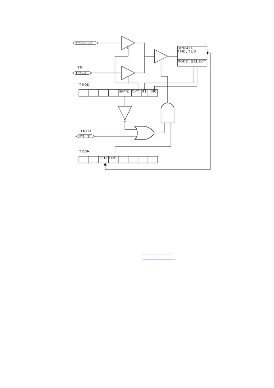
page -228-
© MCS Electronics, 1995-2006
Each counter register has two SFRs associated with it.
For TIMER0 the SFRs are TL0 and TH0.
TL0 is the lowest byte of TIMER0 and TH0 is the highest byte of TIMER0.
These two registers make the timers 16-bit wide.
The timer can operate as a timer or as a counter.
A timer uses the systemclock divided by 12 as the source of its input pulses.
So it increments periodical.
A counter uses external pulses to increment its count.
The external pulses are received at alternative pin P3.4 for TIMER0 and P3.5 for TIMER1.
The timer/counter can be controlled by the run-bit TR0.
You can stop a timer/counter with the statement
You can start a timer/counter with the statement
The timer/counter can also be controlled with the alternative pin P3.2.
This pin is labeled for its alternative INT0-input but it can be used to control the timer.
When GATE is reset the timer/counter is enabled.
When GATE is set the timer/counter is enabled if INT0 is active(low). (provided that the timer
is started)
The timer/counter can operate in four modes:
mode 0 : 13-bit counter.
An interrupt is generated when the counter overflows. So it takes 8192 pulses to
generate the next interrupt.
mode 1 : 16-bit counter.
Mode 1 is similar to mode 0. It implements a 16-bit counter.
It takes 65536 input pulses to generate the next interrupt.
mode 2 : 8-bit auto reload.
TL0 serves as an 8-bit timer/counter.
When the timer/counter overflows the number stored in TH0 is copied into TL0 and the

page -229-
© MCS Electronics, 1995-2006
count continues.
An interrupt is generated each time the counter overflows and a reload is performed.
mode 3 : TIMER1 is inactive and holds its count. (TIMER1).
For TIMER0 in timer mode two 8-bit timers are available and in counter mode one 8-bit
timer is available.
See a datasheet for more details.
The timer/counter can be configured with the CONFIG statement.
CONFIG TIMER0= COUNTER/TIMER, GATE=INTERNAL/EXTERNAL, MODE=0-3
The first argument is the timer/counter you want to configure, TIMER0 in this case.
GATE specifies if external timer control with the INT0 pin is enabled.
MODE specifies the timer/counter mode (0-3).
So CONFIG TIMER0 = COUNTER, GATE = INTERNAL, MODE=2 will configure TIMER0 as a
COUNTER with no external gatecontrol , in mode 2 (auto reload)
When the timer/counter is configured the timer/counter is stopped so you must start it
afterwards with the START TIMER0 statement.
The ON TIMERx statement can be used to respond to a timer/counter interrupt when the
timer overflows.
When the timer/counter is used in mode 2 (auto reload) the reload value can be specified
with the LOAD TIMERx, value statement.
Because it is an 8-bit register a maximum time of 255 uS can be achieved.
So for a period of 10 uS you must supply a value of (256-10) is 246. To make things easier
you can assign the value directly : LOAD TIMERx , 250 will internally be transformed into
256-250=6.
This saves you the trouble of calculating the correct value.
The COUNTER0 and COUNTER1 variables hold the values of timer/counter 0 and 1.
You can also set the timer/counter contents with the COUNTER0 = value statement.
Please note that with the LOAD statement, you can only load a byte value into the
timer/counter.
Because the statement is meant for timer/counter mode 2.
Also note that you can assign a value to the timer/counter with the COUNTER0/COUNTER1
variables. You can not use the TIMER0/TIMER1 in it's place but it does the same thing :
assigning/retrieving the timer/counter.
Port 3 is a unique port because it has alternative functions.
That is you can use it as a port like P3.1 = 1 or SET P3.1 or you can make use of the double
function of this port.
Port
Alternative function
P3.0
RxD receive data for RS-232
P3.1
TxD transmit data for RS-232
P3.2
INT0 interrupt 0 input/timer 0 gate control
P3.3
INT1 interrupt 1 input/timer 1 gate control
P3.4
T0 timer 0 input or counter input
P3.5
T1 timer 1 input or counter input
P3.5
-
page -230-
© MCS Electronics, 1995-2006
P3.7
-
When you make use of the PRINT, INPUT and other RS-232 related statements
P3.0 and P3.1 are used for the RS-232 interface.
When you make use of the INT0/INT1 interrupts, you must connect an interrupt source to the
corresponding pins. A switch for example.
The INTx interrupt can occur on the falling edge of a signal or when the signal is low.
Use the following statements to specify the trigger:
SET TCON.0
Falling edge generates interrupt for INT0.
RESET TCON.0
Low signal generates interrupt for INT0.
SET TCON.2
Falling edge generates interrupt for INT1.
RESET TCON.2
Low signal generates interrupt for INT1.
When TCON.x is RESET the interrupts keep on occurring while the input is low.r When
TCON.x is SET the interrupt only occurs on the falling edge.
To test if a hardware interrupt is generated you can test the TCON.1 and TCON.3 flags.
These flags are set by hardware when an external interrupt edge is detected.
They are reset by the RETURN statement of the interrupt service routine or subroutine.
TCON.1 must be tested for INT0 and TCON.3 must be tested for INT1.
Some uPs have an additional timer named
. It depends on the used chip which
features TIMER2 has.
Ports and Power Up
Port 1 is an 8-bit bi-directional I/O port. Port pins P1.2 to P1.7 provide internal pull-ups.
P1.0 and P1.1 requires external pull-ups. P1.0 and P1.1 also serve as the positive
input(AIN0) and the negative input(AIN1), respectively, of the on-chip precision
analog comparator.
The port 1 output buffers can sink 20 mA and can drive LED displays directly.
When 1s are written to Port 1 pins, they can be used as inputs.
When pins P1.2 to P1.7 are used as inputs and are externally pulled low,
they will source current because of the internal pullups.
Port 3 pins P3.0 to P3.5, P3.7 are seven bi-directional I/O pins with internal pull-ups.
P3.6 is hard wired as an input to the output of the on-chip comparator and is not
accessible as a general purpose I/O pin.
The port3 output buffers can sink 20 mA.
When 1's are written to Port 3 pins they are pulled high by the internal pullups and can be
used as inputs.
Port 3 pins that are externally being pulled low will source current because of the pullups.
Port 3 also serves the functions of various special features of the AT89C2051 as listed below.
Port
Alternative function
P3.0
RxD receive data for RS-232
P3.1
TxD transmit data for RS-232
P3.2
INT0 interrupt 0 input/timer 0 gate control
P3.3
INT1 interrupt 1 input/timer 1 gate control

page -231-
© MCS Electronics, 1995-2006
P3.4
T0 timer 0 input or counter input
P3.5
T1 timer 1 input or counter input
P3.5
-
P3.7
-
Writing to a Port
P1 = 255 will write the value 255 to the port 1, setting all the pins to 1
so all pins can be used as inputs.
P1 = 0 will write the value 0 to port 1, setting al pins to zero.
Reading from a Port
byte = P1 will read the value from port 1 and will assign the value to variable byte.
Setting individual pins of a Port
You can also set individual pins of the ports in BASCOM.
SET P1.0 will set pin P1.0 high.
P1.0 = 1 will also set pin P1.0 high.
RESET P1.0 will set pin P1.0 low.
P1.0 = 0 will also set pin P1.0 low.
At power up both ports are high and can be used an inputs.
Individual bits can be set to use a port both as input/output.
For example : P1 = &B00001111 , will set a value of 15 to port 1.
P1.0 to P1.3 can be used as inputs because they are set high.
How to interface the port pins
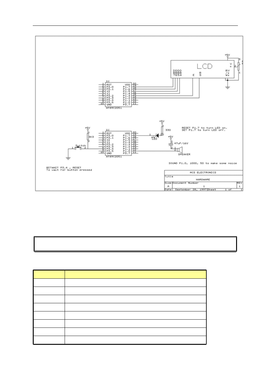
page -232-
© MCS Electronics, 1995-2006
The schematic above shows how to connect a LED as an output, a speaker as an output and
a switch as an input device.
Alternative port-pin functions
The AT89S8252 ports have alternative functions.
The following table shows the alternative functions.
Port pin
Alternate function
P1.0
T2 external count input to timer.counter 2, clock out
P1.1
T2EX timer/counter 2 capture/reload trigger and direction flag
P1.4
/SS Slave port select input
P1.5
MOSI Master data output, slave data input pin for SPI channel
P1.6
MISO Master data input, slave data output pin for SPI channel
P1.7
SCK Master clock output, slave clock input pin for SPI channel
P3.0
RxD serial input port
P3.1
TxD serial output port
page -233-
© MCS Electronics, 1995-2006
P3.2
/INT0 external interrupt 0
P3.3
/INT1 external interrupt 1
P3.4
T0 timer 0 external input
P3.5
T1 timer 1 external input
P3.6
/WR external data memory write strobe
P3.7
/RD external data memory read strobe
/ means active low
Hardware - LCD display
The LCD display can be connected as follows:
LCD-DISPLAY
PORT
PIN
DB7
P1.7
14
DB6
P1.6
13
DB5
P1.5
12
DB4
P1.4
11
E
P1.3
6
RS
P1.2
4
RW
Ground
5
Vss
Ground
1
Vdd
+5 Volt
2
Vo
0-5 Volt
3
This leaves P1.1 and P1.0 and P3 for other purposes.
You can change the LCD pin layout from the Options LCD menu.
You can select the display used with the
CONFIG LCD
statement.
The LCD display operates in 4-bit mode.
See the
statement for operation in 8-bit mode.
BASCOM supports a lot of statements to control the LCD display.
For those who want to have more control the example below shows how to do so.
Acc = 5 'load register A with value
Call Lcd_control 'it is a control value to control the display
Acc = 65 'load with new value (letter A)
Call Write_lcd 'write it to the LCD display
Note that lcd_control and write_lcd are assembler subroutines which can be called from
BASCOM.
See manufacture details from your LCD display for the correct assignment.
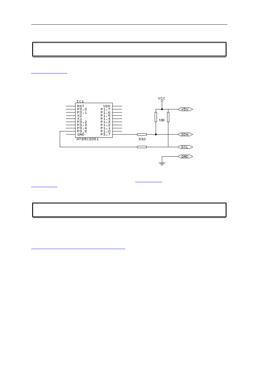
page -234-
© MCS Electronics, 1995-2006
Hardware - I2C
The design below shows how to implement an I2C-bus.
Note that you can select which port pins you want to use for the I2C interface with the
You can also select the SDA and SCL pin with the
statement.
1WIRE
The following information is written by Göte Haluza, thanks!
Dallas Semiconductor (DS) 1wire. This is a brief description of DS 1wirebus when used in
combination with BASCOM. For more detailed explanations about the 1w-bus, please go to
http://www.dalsemi.com/techbriefs/tb1.html
. Using BASCOM, makes the world a lot easier.
This paper will approach the subject from a "BASCOM-user-point-of-view".
1wire-net is a serial communication protocol, used by DS devices. The bus could be
implemented in two basic ways :
With 2 wires, then DQ and ground is used on the device. Power is supplied on the DQ line,
which is +5V, and used to charge a capacitor in the DS device. This power is used by the
device for its internal needs during communication, which makes DQ go low for periods of
time. This bus is called the 1wirebus.
With 3 wires, when +5V is supplied to the VDD line of the device, and DQ + ground as
above. This bus is called the 2wirebus.
So, the ground line is "not counted" by DS. But hereafter we use DS naming conventions.

page -235-
© MCS Electronics, 1995-2006
How it works. (1wire)
The normal state of the bus is DQ=high. Through DQ the device gets its power, and performs
the tasks it is designed for.
When the host (your micro controller (uC)) wants something to happen with the 1w-bus, it
issues a reset-command. That is a very simple electric function that happens then; the DQ
goes active low for a time (480uS on original DS 1w-bus). This put the DS-devices in reset
mode; then (they) send a presence pulse, and then (they) listen to the host.
The presence pulse is simply an active low, this time issued by the device(s).
Now, the host cannot know what is on the bus, it is only aware of that at least 1 DS device is
attached on the bus.
All communication on the 1w-bus is initialised by the host, and issued by time-slots of
active-low on a normally high line (DQ), issued by the device, which is sending at the
moment. The devices(s) internal capacitor supplies its power needs during the low-time.
How you work with 1w-bus
Thereafter, you can read a device, and write to it. If you know you only have 1 sensor
attached, or if you want to address all sensors, you can start with a "Skip Rom" - command.
This means; take no notice about the Ids of the sensors - skip that part of the
c ommunication.
When you made a 1w-reset, all devices of the bus are listening. If you chose to address only
one of them, the rest of them will not listen again before you have made a new 1w-reset on
the bus.
I do not describe BASCOM commands in this text - they are pretty much self-explaining. But
the uC has to write the commands to the bus - and thereafter read the answer. What you
have to write as a command depends on devices you are using - and what you want to do
with it. Every DS chip has a datasheet, which you can find at
http://www.dalsemi.com/datasheets/pdfindex.html
. There you can find out all about the
actual devices command structure.
There are some things to have in mind when deciding which of the bus-types to use.
The commands, from BASCOM, are the same in both cases. So this is not a problem.
The +5V power-supply on the VDD when using a 2wire-bus has to be from separate power
supply, according to DS. But it still works with taking the power from the same source as for
the processor, directly on the stabilising transistor. I have not got it to work taking power
directly from the processor pin.
Some devices consume some more power during special operations. The DS1820 consumes a
lot of power during the operation "Convert Temperature". Because the sensors knows how
they are powered (it is also possible to get this information from the devices) some
operations, as "Convert T" takes different amount of time for the sensor to execute. The
command "Convert T" as example, takes ~200mS on 2wire, but ~700mS on 1wire. This has
to be c onsidered during programming.

page -236-
© MCS Electronics, 1995-2006
And that power also has to be supplied somehow.
If you use 2wire, you don't have to read further in this part. You can simultaneously "Convert
T" on all the devices you attach on the bus. And save time. This command is the most
power-consuming command, possible to execute on several devices, I am aware of.
If you use 1wire, there are things to think about. It is about not consuming more power than
you feed. And how to feed power? That depends on the devices (their consumption) and
what you are doing with them (their consumption in a specific operation).
Short, not-so-accurate description of power needs, not reflecting on cable lengths
Only the processor pin as power supplier, will work < 5 sensors. (AVR, 1w-functions use an
internal pull-up. 8051 not yet tested). Don't even think of simultaneous commands on
multiple sensors.
With +5V through a 4K7 resistor, to the DQ-line, 70 sensors are tested. But, take care, cause
issuing "Convert T" simultaneously, would cause that to give false readings. About ~15
sensors is the maximum amount of usable devices, which simultaneously performs some
action. This approach DS refers to as "pull-up resistor".
With this in mind, bus up to 70 devices has been successfully powered this way.
The resistor mentioned, 4K7, could be of smaller value. DS says minimum 1K5, I have tested
down to 500 ohm - below that the bus is not usable any more. (AVR). Lowering the resistor
feeds more power - and makes the bus more noise -resistant. But, the resistor minimum
value is naturally also depending on the uC-pin electric capabilities. Stay at 4K7 - which is
standard recommendation.
DS recommends yet another approach, called "strong pull-up" which (short) works via a
MOS-FET transistor, feeding the DQ lines with enough power, still on 1wire, during
power-consuming tasks. This is not tested, but should naturally work. Cause this functionality
is really a limited one; BASCOM has no special support for that. But anyway, we tell you
about it, just in case you wonder. Strong pull-up has to use one uC pin extra - to drive the
MOS-FET.
Cable lengths (this section is only for some limited understanding)
For short runs up to 30 meters, cable selection for use on the 1W bus is less critical. Even flat
modular phone cable works with limited numbers of 1-Wire devices. However, the longer the
1W bus, the more pronounced cable effects become, and therefore the greater importance
placed on cable selection.
For longer distances, DS recommends twisted-pair-cable (CAT5).
DS standard examples show 100 meters cable lengths, so they say, that's no problem. They
also show examples with 300m cabling, and I think I have seen something with 600-meter
bus (but I cant find it again).
Noise and CRC
The longer cable and the noisier environment, the more false readings will be made. The
devices are equipped with a CRC-generator - the LSByte of the sending is always a
checksum. Look in program examples to learn how to re-calculate this checksum in your uC.
AND, if you notice that there are false readings - do something about your cables. (Shield,
lower resistor)

page -237-
© MCS Electronics, 1995-2006
Transfer speed
On the original 1w-bus, DS says the transfer speed is about 14Kbits /second. And, if that was
not enough, some devices has an overdrive option. That multiplies the speed by 10. This is
issued by making the communication-time-slots smaller (from 60 uS to 6uS ) which naturally
will make the devices more sensitive, and CRC-error will probably occur more often. But, if
that is not an issue, ~140Kbit is a reachable speed to the devices. So, whatever you thought
before, it is FAST.
The BASCOM scanning of the bus is finds about 50 devices / second , and reading a specific
sensors value to a uC should be about 13 devices / second.
Topology
Of the 1w-net - that is an issue we will not cover so much. Star-net, bus-net? It seems like
you can mix that. It is a bus-net, but not so sensitive about that.
The benefit of the 1w-bus
Each device is individual - and you can communicate with it over the media of 2 wires. Still,
you can address one individual device, if you like. Get its value. There are 64 ^ 2 unique
identifications-numbers.
Naturally, if lot of cables are unwanted, this is a big benefit. And you only occupy 1 processor
pin.
DS supplies with different types of devices, which all are made for interfacing an uC -
directly. No extra hardware. There are sensors, so you can get knowledge about the real
world, and there are also potentiometers and relays, so you can do something about it. On
the very same bus.
And the Ibutton approach from DS (ever heard of it?) is based on 1wire technology. Maybe
something to pick up.
BASCOM let you use an uC with 1wire-devices so easy, that (since now) also has to count as
a benefit - maybe one of the largest. ;-)
The disadvantages of the 1w-bus
So far as I know, DS is the only manufacturer of sensors for the bus. Some people think their
devices are expensive. And, until now, it was really difficult to communicate with the
devices. Particularly when using the benefit of several devices on one bus. Still some people
say that the 1w-bus is slow - but I don't think so.
Göte Haluza
System engineer
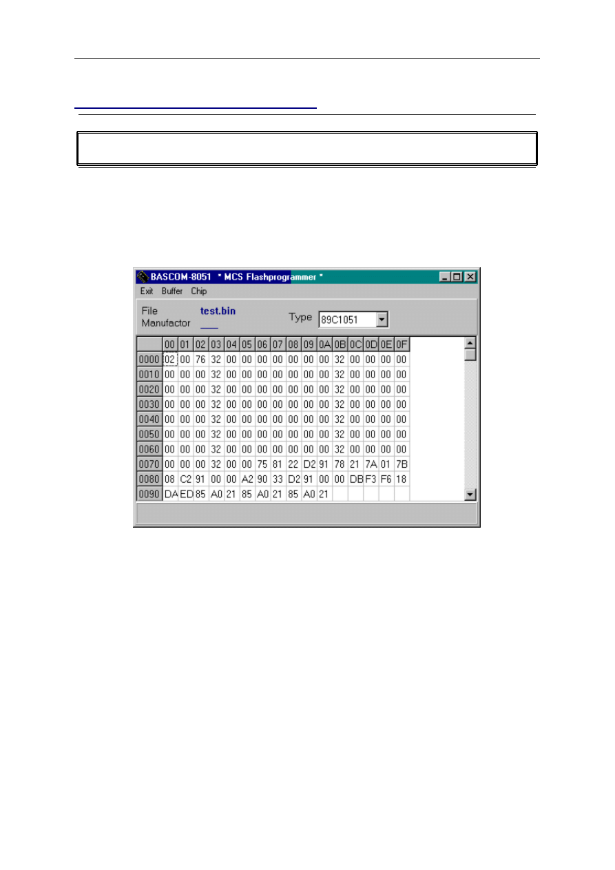
page -238-
© MCS Electronics, 1995-2006
Supported Programmers
MCS FLASH PROGRAMMER
There are different models of the MCS Flash programmer, but all of them are compatible with
the driver software.
The MCS Flash programmer is a parallel printer port based programmer.
It can only program the ATMEL 89C1051 , AT89C2051 and AT89C4051.
Select the correct printer port address before you run the programmer.
Be sure to switch on the power supply before running BASCOM.
When you run the programmer, the buffer will be filled automatically with your program data.
The programmer works with binary files. The following menu options are available.
Exit
Exit the programmer.
Buffer clear
Clear the buffer. Thats is, fill it with zero bytes.
Buffer Read from disk
Load a file into the buffer. By default the current program.BIN file is selected.
Select a file with the file selection dialogbox and press the Ok-button.
Buffer Write to disk
Write the content of the buffer to a file.

page -239-
© MCS Electronics, 1995-2006
Note that the filesize is 1024 ,2048 or 4096 bytes depending on the chip type.
Buffer read from chip
Read the content of the FLASGROM into the buffer.
If the lockbits are set all bytes will return FF.
Buffer Write to chip
Program the chip with the content of the buffer.
The chip is erased before the buffer is written to the chip.
Buffer Verify
Compares the content of the buffer with the content of the chip.
Buffer program chip
Erases the chip, writes the buffer to the chip and finally verifies the buffer with the chip.
Chip get type
Retrieves the chip type. AT89C1051 , AT89C2051 or AT89C4051.
Chip Erase
Erases the chip. Lock bits are also erased.
Chip Set lockbit 1
When LB1 is set the chip can not be programmed anymore.
Chip Set lockbit 2
When LB2 is set the chip can not be programmed nor can it be verified (read)
Use LB1 and LB2 together for securing your program.
Options LPT1 .. LPT3
Select the printer port the programmer is connected to.
Option Port delay
Because computers become faster every day and the hardware is run by software a delay can
be specified for very fast computers.
A value of 5 is used on a 486DX266. You must increase the value on faster computers if
problems occur.
The default is 0, and for best results, 0 should be used.

page -240-
© MCS Electronics, 1995-2006
MCS SPI programmer
The MCS SPI programmer is a parallel printer port based SPI-programmer.
It is a modified design of Jakub Jiricek's SPI-programmer. (two LED's were added)
The programmer can program the AT89S52 which has an extra 2048 bytes built in EEPROM
for storing data and the AT89S53.
The nice thing about SPI-programmable chips is that the chip can be programmed in circuit.
You only must design your application so that the SPI-port pins will not be pulled low.
The following menu options are available:
File exit
Will exit the programmer.
Write code
Will program the chip with the current programs binary image.
Write data
Will ask for a file and will write the data to the EEPROM.
Verify code
Will verify the programs binary image with the chip content.
Verify data
Will verify a file with the chips EEPROM content.
Read code
Will ask for a filename and will write the chip content to the file.
Read data
Will ask for a filename and will write the EEPROM content to the file.
Chip reset
Will reset the chip.
Chip erase
Will erase the chip.
Chip set lockbits
Will set the selected lock bits.
The following use feedback was received:
I have at last found my problem with the SPI flash programmer designed by
Jakub Jiricek.
My PC's LPT port was set to NORMAL mode in the BIOS. Symptoms include
normal reset pulse but very slow progress bar with eventual failure to verify.
Correct programmer operation was achieved by changing to EPP (enhanced
parallel port) mode in BIOS. I can only assume that the s/w must be using

page -241-
© MCS Electronics, 1995-2006
one line in bi-directional mode. Of course, this "fix" may only apply to my PC.
Blow IT Flashprogrammer
The Blow IT flashprogrammer is a parallel printer port based programmer and can only erase,
and program a chip. The programmer works only with the AT89C1051 to AT89C4051 chips.
The programmer uses the same interface as the MCS Flashprogrammer, but doesn't support
all the features due it's design. So for a description read the
PG2051 flash programmer
The PG2051 is a serial comport based programmer and can program AT89C1051 and
ATC2051 chips only. A nice feature is that the programmer can serve as an simulator too.
The programmer works with Intel HEX files only.
The following menuoptions are available:
File Exit
This will exit the programmer.
Buffer read from disk
This allows you to load a binary file from disk.
The current projects binary file is always loaded automatic.
Buffer write to disk
This option can be used to save the buffer to disk.
Buffer download
With this option you send the programs' hex file to the programmer/simulator.
After it is sent, you can program the chip or simulate the program.
Buffer retrieve
Use this option to load the chipcontent into the buffer.
Buffer verify
This option will verify the buffer with the chip content.
Buffer autoprogram
This option will erase the chip, download the buffer, program the chip and finally verifies the
chip.
Chip get type
To identify the chip you can select this option.
The radio-button 89C1051 or 89C2051 will be set.
Chip set lockbit 1

page -242-
© MCS Electronics, 1995-2006
Set lockbit 1 so the chip can not be programmed anymore.
Chip set lockbit 2
Set lockbit 2 so the chip can not be programmed or verified/read anymore .
Chip erase
Erases the chip.
Chip program
Will program the chip with the downloaded buffer.
Chip simulate
Will simulate the programmed program. This saves swapping the chip in and out of the target
application.
PG302 programmer
The PG302 is a serial comport based programmer.
The programmer can program a wide variety of chips with additional adapters.
The BASCOM interface is designed to look similar with the original PG302 driver software.
You must select the target chip from the device list.
Some chips will enable the memory radio buttons. For example the AT89S8252.
You can select the memory-area with the radio buttons in these cases.
Blank check
Will perform a blank check on the chip. That is, every memory location will be checked if it is
equal to 255 (hex FF), indicating an un-programmed byte.
Erase
Will erase the chip. All memory locations will be set to 255.
Program
Will program the chip with the current program.
If EEPROM-memory is selected, you will be asked for a filename.
Verify
Will verify the current program with the target chip.
Read
Will read the target chip and saves the result to a file.
Set lockbit
Will set the selected lock bits.
You must select the lock bits first. The lock bits to set depend on the selected target chip.
Auto erase
When this checkbox is selected, the target chip will be erased before it will be programmed.

page -243-
© MCS Electronics, 1995-2006
Auto verify
When this checkbox is selected, the result will be verified after each programming.
SE512 or SE514 programmer
The SE512 and SE514 are parallel printer port based programmers.
The nice thing about these programmers is that they can simulate the application too. This
has the advantage that no device swapping is needed until your application works like you
want. The SE512 can program the AT89C1051 to AT89C4051. The SE514 can program larger
chips too.
Buffer clear
Will clear the buffer.
Buffer load from file
With this option you can load a file into the buffer. By default the current program is loaded
into the buffer.
Buffer save to file
With this option you can save the buffer to a binary file.
Chip Write buffer into chip
With this option you program the chip.
Chip Read chipcode into buffer
This option will read the target device its memory into the buffer.
Chip Blank check
Performs a blank check on the target device. A chip is considered blank if every memoryl
ocation contains 255 (FF hex)
Chip Erase
Will erase the target chip.
Chip verify
Will verify the buffer with the chipcontent.
Chip autoprogram
Will erase, program and verify the chip.
Note that the targetchip will be detected automatic. When the targetchip can't be detected,
the menu options will not work.
SE-812
The SE-812 from Sample Electronics is a programmer for the aduc812.
page -244-
© MCS Electronics, 1995-2006
The programmer is well suited for in circuit programming.
Since it is a serial programmer that operates via the COM port, the programming is done with
the terminal emulator. When you select the SE812 from the programmer options there will be
an additional menu in the terminal emulator.
- Erase chip. This option will erase both the code flash and the EEPROM.
- Erase code flash. This option will erase only the code flash memory.
- Program chip. This will program the chip with the current program.
- Auto program. This will erase the chip and program the chip.
The programmer works only with version 2.00 of the boot loader.
Sample Electronics ISP programmer
The simple cable programmer was submitted by Sample Electronics.
They produce professional programmers too. This simple programmer you can make yourself
within a 10 minutes. And only a few resistors are needed.
The operation is the same a for the
What you need is a DB25 centronics male connector, a flatcable and a connector that can be
connected to the target MCU board.
The connections to make are as following:
DB25 pin
Target MCU pin(AT89S8252)
DT104
2, D0
MOSI, pin 6
J5, pin 4
4, D2
RESET, pin 9
J5, pin 8
5, D3
CLOCK, pin 8
J5, pin 6
11, BUSY
MISO, pin 7
J5, pin 5
18-25,GND
GROUND
J5, pin 1
The MCU pin numbers are shown for an 8252!
Note that 18-25 means pins 18,19,20,21,22,23,24 and 25
You can use a small resistor of 100 ohm in series with the D0, D2 and D3 line in order not to
short circuit your LPT port in the event the MCU pins are high.
But it was tested without these resistors and my PC still works :-)
Tip : when testing programmers etc. on the LPT it is best to buy an I/O card for your PC that
has a LPT port. This way you dont destroy your LPT port that is on the motherboard in the
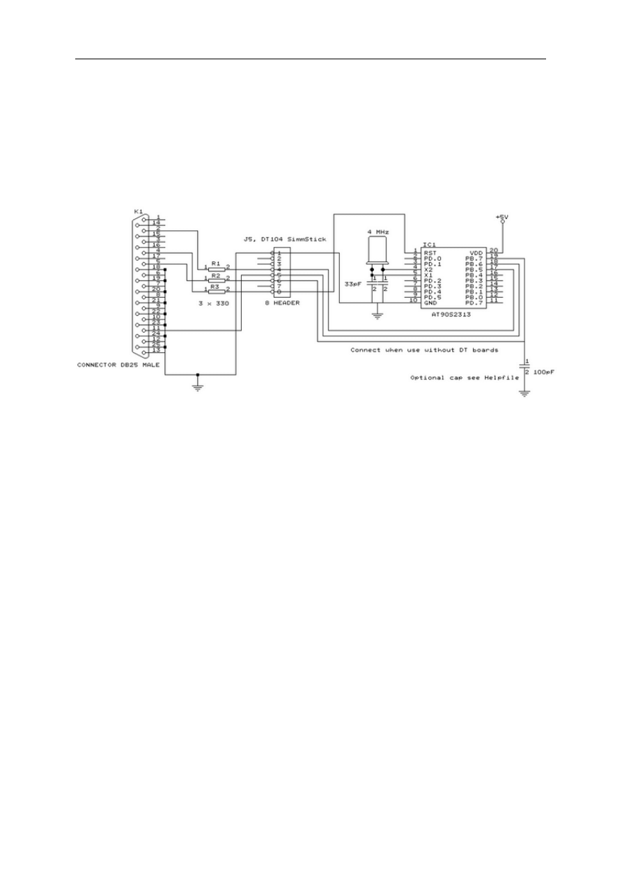
page -245-
© MCS Electronics, 1995-2006
event you make a mistake!
The following picture shows the connections to make. Both a setup for the DT104 and stand
alone PCB are shown.
I received the following useful information :
Hi Mark,
I have been having spurious success with the simple cable programmer from
Sample Electronics for the AVR series.
After resorting to hooking up the CRO I have figured it out (I think). When
trying to identify the chip, no response on the MISO pin indicates that the
Programming Enable command has not been correctly received by the target.
The SCK line Mark/Space times were okay but it looked a bit sad with a slow
rise time but a rapid fall time. So I initially tried to improve the rise
time with a pullup. No change ie still could not identify chip. I was about
to add some buffers when I came across an Atmel app note for their serial
programmer
"During this first phase of the programming cycle, keeping the SCK line
free from pulses is critical, as pulses will cause the target AVR to loose
syncronisation with the programmer. When syncronisation is lost, the only
means of regaining syncronisation is to release the RESET line for more
than 100ms."
I have added a 100pF cap from SCK to GND and works first time every time
now. The SCK rise time is still sad but there must have been enough noise

page -246-
© MCS Electronics, 1995-2006
to corrupt the initial command despite using a 600mm shielded cable.
This may be useful to your users.
Regards,
Mark Hayne
CYGNAL JTAG Programmer
The CYGNAL JTAG programmer comes with the CYGNAL development kit and is also available
from
www.sample.co.kr
All tests were performed with the programmer/evaluation board from Sample Electronics.
The Cygnal JTAG programmer is controlled by a COM port.
You need to select a free COM port of your PC that is connected to the programmer.
When you program the cygnal chip BASCOM will erase and program the chip.
Futurelec
The Futurelec programmer from
www.futurlec.com
is an ISP programmer for the 89S8252.
All tests are performed with the AT89S8252 board from Futurelec Electronics.
JPK Systems X-programmer
The JPK Systems X-programmer is a serial comport based SPI-programmer.
It is fully optical isolated and so an ideal device for industrial equipment.
It supports AVR chips too, but these aren't supported in BASCOM of course so there is only
support for the 89S8252 and the 89S53.
Since it is serial based, the support is placed in the terminal emulator.
After selecting the JPK programmer, there will be additional menu options available in the
terminal emulator. All these options can be found under the JPK menu.
The transfer between the PC and the programmer is implemented with the X-modem CRC
protocol.
Select device

page -247-
© MCS Electronics, 1995-2006
Use this option to select the targetdevice. You can choose between the 89S8252 and the
89S53.
Erase
Erase the target chip.
Read code
Will read the codememory from the chip. You will be asked for a filename first.
Program chip
Will program the targetchip with the current program.
Set lockbits
Will set the lockbits of the targetchip. All lockbits will be set.
Read EEPROM
Will save the EEPROM data into a file. This only applies to the AT89S8252.
Write EEPROM
Will program the EEPROM with a file. This only applies to the AT89S8252.
Of course all commands can be typed manually too, but you must set the terminal emulator
communication settings to 2400N82 in that case.
Peter Averill's TAFE programmer
The TAFE flashprogrammer is a parallel printer port based programmer and can be build with
the DT004 and DT206 SimmSticks from Dontronics. The programmer can program only
AT89C1051 to AT89C4051 chips.
Peter also has schematics available on the web so you can build your own PCB.
The programmer supports all the usual features except the 'read signature' feature.
Thats is why you have to select the used chip yourself from the mnu.
The programmer uses the same interface as the MCS Flashprogrammer, so for a description
read the
MCS Flashprogrammer
help.
I got some feedback from a user that had problems with his programmer.
he added 5K1 pullup resistors to +5V. This is shown in the picture below. The dots (11) must
each have a resistor of 5K1 to +5V.
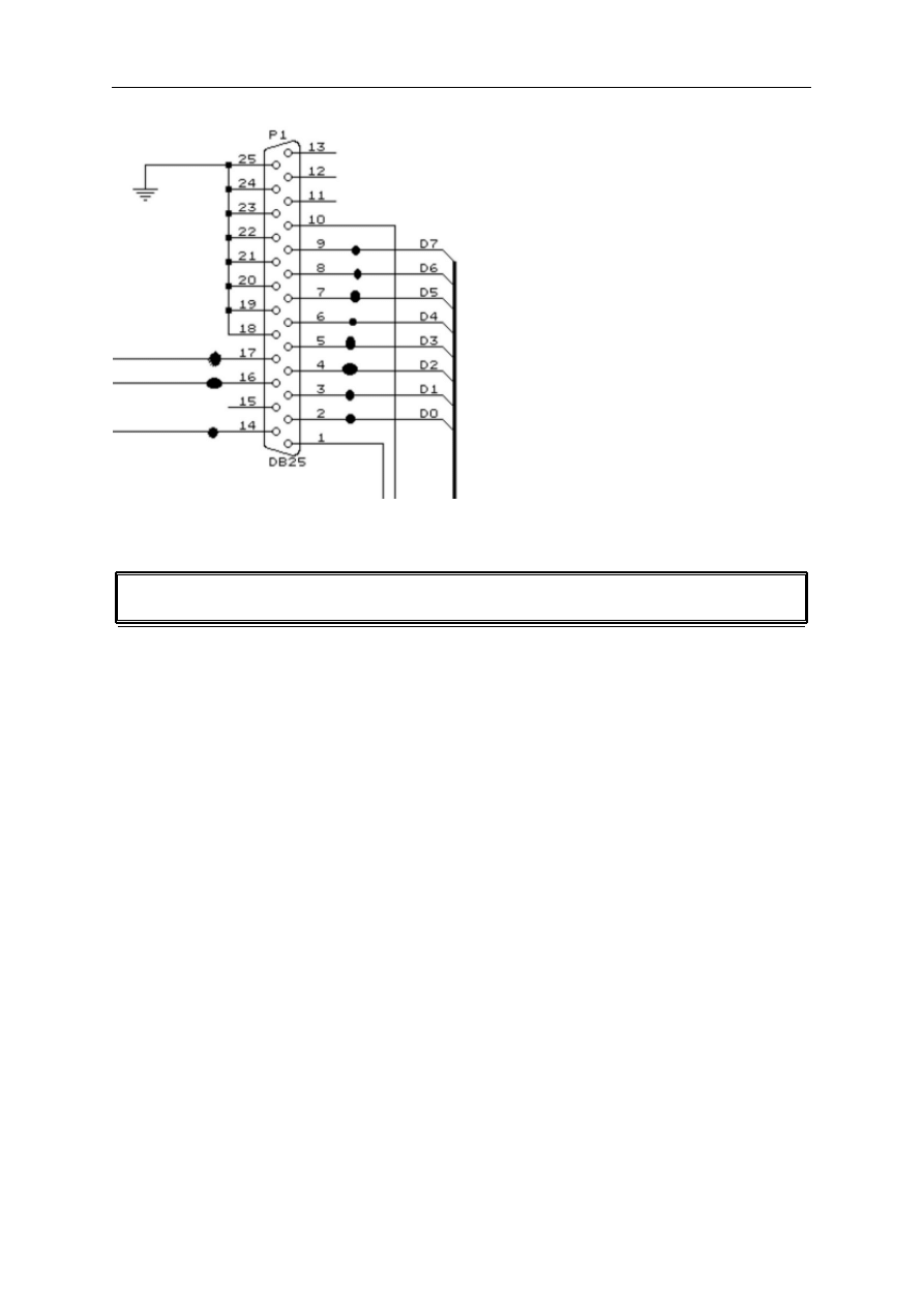
page -248-
© MCS Electronics, 1995-2006
STK200/300 ISP Programmer
The STK200 and STK300 are AR starter kits from Atmel.
They come with a parallel printer port programmer dongle for in system programming of the
chips.
This dongle can be used to program the 89S8252 or 89S53.
For those who don't have this kit and the programmer the following schematic shows how to
make your own programmer:
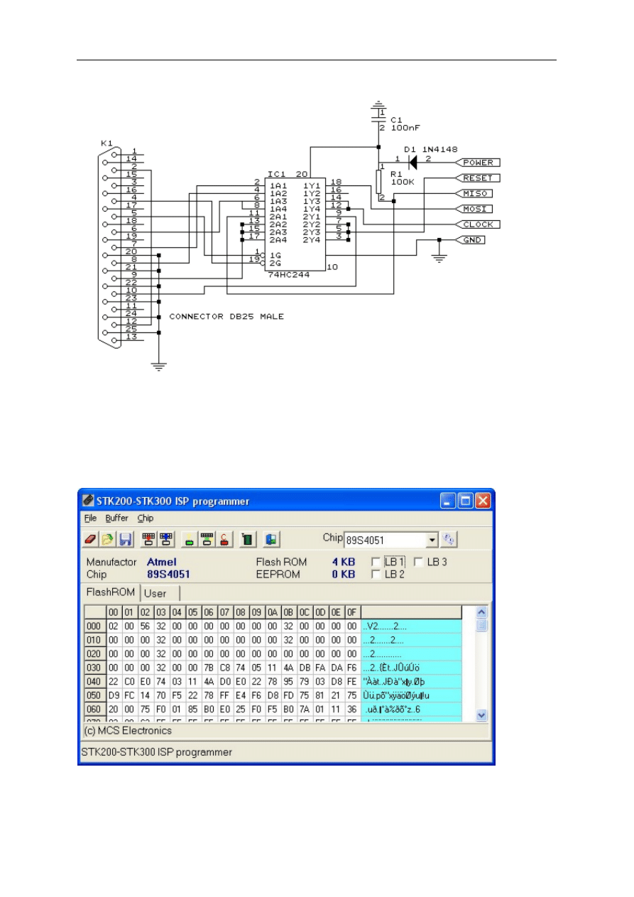
page -249-
© MCS Electronics, 1995-2006
The dongle has a chip with no identification but since the schematic is all over the web, I
have included it. Kanda also sells a very cheap separate programmer dongle. So I suggest
you buy this one!
MCS also sells a compatible dongle.
The following screen will pop up when you have selected this programmer:
You must select the chip you use. By selecting the FlashROM TAB or the EEPROM TAB you can
write that info to the chip. When the chip does not have EEPROM memory, the EEPROM TAB
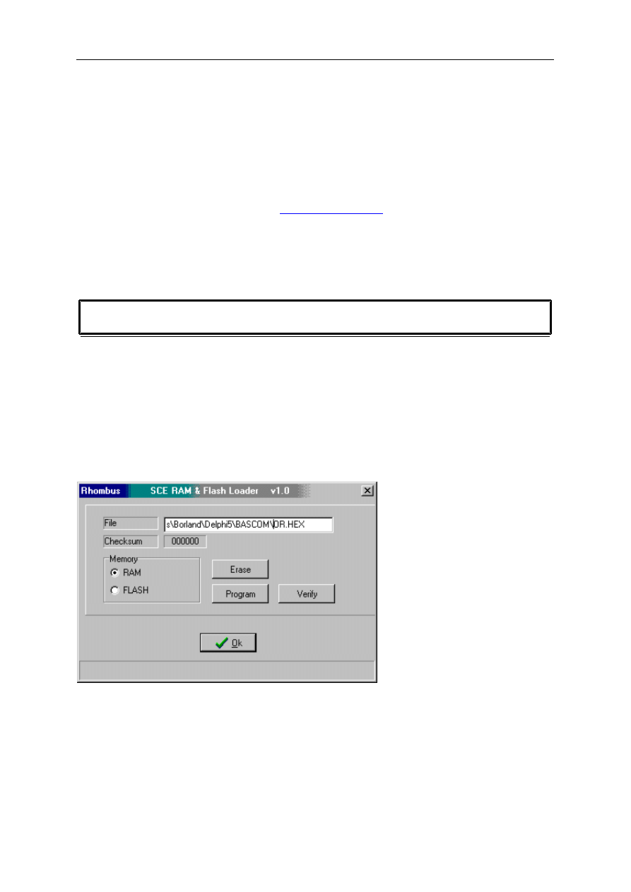
page -250-
© MCS Electronics, 1995-2006
will not be visible.
When the chip such as the 89S8253, 89S2051 or 89S4051 has USER data, an additional TAB
will be shown.
This is intended to read/write the user data.
When you select auto Flash, pressing F4 from the IDE will program the chip automatic and
the window will not be displayed.
When Code + Data is selected from the
data are programmed.
Rhombus SCE-51
Rhombus developed the SCE-51. A powerful small 8051 micro processor board with on board
RAM and FLASHROM and bootloader.
In addition the board serves as an in circuit emulator.
Transferring your program to RAM goes very fast. Faster than loading it into the traditional
FLASHROM. So during debugging it is well suited for debugging large applications.
When you select the SCE-51, the following window will appear when you press F4.
The filename is automatic filled.
The original SCE-51 software from Rhombus has much more options and BASCOM only
supports programming to RAM and FLASH.
You must select the target memory before you click the Program button.
By clicking the Erase button you can erase the memory.
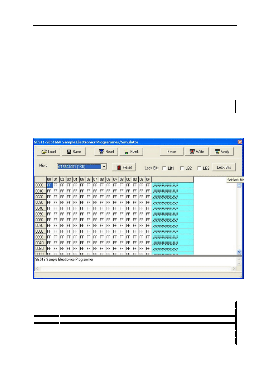
page -251-
© MCS Electronics, 1995-2006
During programming a status bar will be shown.
The baud rate is fixed to 19200 baud. Support for 115200 baud will be added later.
SE511-SE516 programmer
The SE511-SE516 can be used for the SE511 and SE516 programmers from Sample
Electronics.
These programmers are serial programmers. They require a COM port.
When you launch the programmer, the current program will be loaded into the memory.
You can also use the LOAD button to load a program into the buffer.
Reset
This button will reset the programmer and will determine the used chip.
Load
Load a binary or Intel HEX file into the buffer
Save
Save the current buffer to file
Read
Read the chip flash content
Blank
Test if a chip is blank
Erase
Erase (blank) a chip

page -252-
© MCS Electronics, 1995-2006
Write
Write(program) the buffer into the chip
Verify
Verify if the buffer is the same as the chip content
Lock Bits
Write the selected lock bits

page -253-
© MCS Electronics, 1995-2006
BASCOM Misc
Error messages
The following table list all errors that can occur.
Nr
Error message
1
BASIC sourcefile not found
2
Code does not fit into FLASHROM
3
Unknown statement
4
Extension expected
5
Wrong variable or variable not dimensioned
6
Two parameters expected
7
No more space for BIT
8
No more space for BYTE
9
No more space for INTEGER/WORD
10
Wrong type (BIT,BYTE or INTEGER/WORD) expected
11
AS expected by DIM
12
, expected
13
Unknown interrupt
14
IF THEN expected
15
FOR, DO or WHILE expected
16
Wrong number of parameters
17
Illegal compare (=,>,<,<>,<=,>=) expected
18
THEN expected
19
TIMER0 or TIMER1 expected
20
DO expected
21
UNTIL expected
22
Illegal mathematical operation
23
FOR expected
24
WHILE expected
25
Variable not dimensioned
26
Source file not found
27
Label not found
100-134 These are internal assembler warnings. Contact MCS
Electronics .
135
Too many RAM used
136
Variable already dimensioned

page -254-
© MCS Electronics, 1995-2006
137
Constant must be in range of 1-8
138
Baudrate not supported with selected frequency
139
9 parameters expected
140
COUNTER0 or COUNTER1 expected.
141
= expected.
142
Maximum of 128 aliases statements allowed
143
Duplicate label
144
Value does not fit into byte
145
No more space for external BYTE
146
No more space for external INTEGER/WORD
147
No more space for STRING
148
Call outside 2048 page range. Use $LARGE to compile this
program.
150
Unsupported LCD display
151
Unsupported mode
152
Variable not found or dimensioned
153
Wrong type (BYTE,INTEGER/WORD, LONG or STRING)
expected
154
: expected
155
SELECT CASE expected
156
Numeric variable expected
157
(external) LONG expected
158
Value does not fit into Integer
159
Value does not fit into Word
160
Value does not fit into Long
161
* xxx (xxx=length) expected
162
Variable expected
163
Small string expected.
164
Variable not DIMensioned
166
Three parameters expected
167
1 or 0 expected
168
4 or 8 expected
170
Wrong value for WATCHDOG
171
Wrong parameter for I2C
172
Byte,Integer or Long expected
173
Variable expected
174
Integer or Long expected
175
Value does not fit into bit
176
Variables must be of the same type

page -255-
© MCS Electronics, 1995-2006
177
Illegal operation
178
Value doesn't fit
179
Not supported
180
Illegal operation in PlaceValue
181
Constant or Internal byte or integer expected for index
182
Invalid device
183
Channel not opened
184
Device already open
185
Device was not open
186
Value does not fit into byte
187
IF ... THEN not allowed on same line as CASE
188
END IF expected
189
CONST expected
190
Channel expected (#x)
191
ALIAS already used
192
Word or Integer expected
193
CONST already defined
194
= expected
195
TO expected
196
Jump out of address range
197
RNDDATA variable not dimensioned
198
') expected
199
'( expected
206
Library file not found
207
Library file already registered
208
) expected
209
( expected
210
LEFT or RIGHT expected
211
External routine not found
212
Valid number must be in range from 1-16
213
Numeric constant expected
214
No SUB found.
215
Already in SUB
216
Wrong mode
217
NOINT expected
218
+ must be between {}
219
Address >127, use indirect addressing
999
DEMO allows 2048 bytes of code only

page -256-
© MCS Electronics, 1995-2006
Compiler Limits
There are some limitations to the compiler :
You can perform only one calculation in a formula.
Good False
a = a * b1 a = a * b1 + c
Maximum allowed labels
5000
Maximum allowed variable names
1000
Maximum number of INTEGER/WORD variables
10*
Maximum number of BYTE variables
20*
Maximum number of BIT variables
120*
Maximum number of STRING variables
Up to available
external memory
Maximum number of ALIAS statements
128
*Depending on the used statements and the used variables of the other types.
A maximum of 32 bytes is used internally. This depends on the used statements.
The stack uses some space too. So it depends on the used statements how much variables
you can use. In the worst case (32+16+8) = 56 bytes are used.
You can find out by
how much bytes are used by your program.
When you have a micro such as the 89S8252 with 256 bytes of internal memory, you can
have more variables.
8 used bit vars will use 1 byte;
1 used byte will use 1 byte;
1 used integer/word will use 2 bytes;
1 used long will use 4 bytes;
1 used single will use 4 bytes;
1 string with a length of 10 bytes will use 11 bytes.
Maximum nesting :
FOR .. NEXT
50
IF .. THEN
50
DO .. LOOP
50
WHILE .. WEND
50
SELECT .. CASE
25

page -257-
© MCS Electronics, 1995-2006
Reserved words
The following table shows the reserved BASCOM statements.
Red
keywords can only be used on systems, which can address external RAM memory.
!
;
$INCLUDE
$NOINIT
$NOSP
$NOBREAK
$BAUD
$BGF
$DEFAULT
$CRYSTAL
$LARGE
$LCD
$ROMSTART
$RAMSIZE
$RAMSTART
$SERIALINPUT
$SERIALOUTPUT
$SIM
1WRESET
1WREAD
1WWRITE
ACK
ALIAS
ABS()
AND
AS
ASC()
BAUD
BCD()
BIT
BITWAIT
BLINK
BOOLEAN
BREAK
BYTE
CALL
CASE
CLS
CHR()
CONFIG
CONST
COUNTER
COUNTER0
COUNTER1
CPEEK()
CURSOR
DATA
DEC
DECLARE
DEFBIT
DEFBYTE
DEFLCDCHAR

page -258-
© MCS Electronics, 1995-2006
DEFINT
DEFWORD
DELAY
DIM
DISABLE
DISPLAY
DO
DOWNTO
ELSE
ELSEIF
ENABLE
END
ERR
EXIT
EXTERNAL
FOR
FOURTH
FOURTHLINE
GATE
GETAD
GOSUB
GOTO
HEXVAL()
HIGH()
HIGHW()
HOME
I2CRECEIVE
I2CSEND
I2CSTART
I2CSTOP
I2CRBYTE
I2CWBYTE
IDLE
IF
INC
INKEY
INP()
INPUT
INPUTHEX
INT0
INT1
INTEGER
INTERNAL
IS
LCD
LCDHEX
LEFT
LEFT()
LOAD
LOCATE
LONG
LOOKUP
LOOP
LOW()
LOWW()
LOWER
LOWERLINE
MAKEBCD()
MAKEDEC()
MAKEINT()

page -259-
© MCS Electronics, 1995-2006
MID()
MOD
MODE
NACK
NEXT
NOBLINK
NOSAVE
NOT
OFF
ON
OR
OUT
P0-P6
PEEK()
POKE
POWERDOWN
PSET
PRINT
PRINTHEX
PRIORITY
READ
READEEPROM
REM
RESET
RESTORE
RETURN
RIGHT
RIGHT()
RND()
ROTATE
SELECT
SERIAL
SET
SHIFT
SHIFTLCD
SHIFTCURSOR
SHIFTIN
SHIFTOUT
SHOWPIC
SOUND
SPACE()
START
STEP
STR()
STRING()
STOP
STOP TIMER
SUB
SWAP
THEN
THIRD
THIRDLINE
TIMEOUT
TIMER0
TIMER1
TO
UNTIL
UPPER
UPPERLINE
VAL()

page -260-
© MCS Electronics, 1995-2006
WAIT
WAITKEY
WAITMS
WATCHDOG
WRITEEEPROM
WEND
WHILE
WORD
XOR
XRAM
The internal registers are also reserved words (variables)
TCON
P1
SCON
IE
P3
IP
PSW
ACC
B
SP
DPL
DPH
PCON
TMOD
TL0
TL1
TH0
TH1
SBUF
Note that you can change the internal registers with the
settings from the
Options menu.

page -261-
© MCS Electronics, 1995-2006
Microprocessor support
Microprocessor support
Some microprocessors have additional features compared to the AT89C2051/8051.
8032/8052/AT89S8252
AT89S8252
WATCHDOG
DATA EEPROM
Alternative port-pin functions
80515,80535,80517,80535
GETAD
WATCHDOG
BAUDRATE GENERATOR
INTERRUPTS and PRIORITY
80517,80537
GETAD
WATCHDOG
BAUDRATE GENERATOR
BAUDRATE GENERATOR1
INTERRUPTS and PRIORITY
89C51+
ADUC812
CONFIG ADUC812
Using the DAC
The additional interrupts are :
ADCI , I2CSPI and PSMI
To enable them :
ADCI, ENABLE I2CSPI, ENABLE PSMI
To disable them:
DISABLE
ADCI, DISABLE I2CSPI, DISABLE PSMI
To set the priority to the highest level in addition to the normal priority interrupt sources:
PRIORITY
SET|RESET ADCI
80552

page -262-
© MCS Electronics, 1995-2006
GETAD(channel, prm) where channel is the channel and the prm is a paramter that may be 0
for software trigger only or 32(dec) for trigger by rising edge on STADC too.
To use the PWM of the 80552 :
Dim Pwp As Byte, Pwa as Byte, Pwb as Byte
Pwp = 200 'set output frequency (0 - 255)
Pwa = 50 'set channel 0 (a) pulse width (0 - 255)
Pwb = 0 'set channel 1 (b) pulse width (0 - 255)
Do
Gosub Pwm
Loop
Pwm:
$asm
MOV PWMP , {Pwp}
MOV PWM0 , {Pwa}
MOV PWM1 , {Pwb}
$end asm
Return
TIMER2 in 8032 and compatibles
Some microprocessors have an additional timer on board : TIMER2.
This section describes the 8032 compatible TIMER2 and is not compatible with the TIMER2
found in the 80C535 and others.
TIMER2 is a 16-bit timer/counter which can operate as either an event timer or an event
counter. TIMER2 has three main operating modes : capture, auto-reload(up or down
counting) , and baud rate generator.
When using the TIMER2 interrupt, you must reset the interrupt bit that caused the interrupt
yourself in the ISR handler.
Capture mode
In the capture mode there are two options :
16-bit timer/counter which upon overflowing sets bit TF2, the TIMER2 overflow bit. This
bit can be used to generate an interrupt.
Counter mode :
CONFIG TIMER2 = COUNTER, GATE = INTERNAL, MODE = 1
Timer mode:
CONFIG TIMER2=TIMER, GATE= INTERNAL,MODE =1
As above but with the added future that a 1 to 0 transition on at external input T2EX
causes the current values in the TIMER2 registers TL2 and TH2 to be captured into the
capture registers RCAP2L and RCAP2H.

page -263-
© MCS Electronics, 1995-2006
Counter mode:
CONFIG TIMER2 = COUNTER, GATE = EXTERNAL, MODE = 1
Timer mode:
CONFIG TIMER2=TIMER,GATE=EXTERNAL,MODE=1
In addition the transition at T2EX causes bit EXF2 in T2CON to be set and EXF2 like TF2 can
generate an interrupt.
The TIMER2 interrupt routine can interrogate TF2 and EXF2 to determine which event caused
the interrupt.
(there is no reload value in this mode. Even when a capture event occurs from T2EX the
counter keeps on counting T2EX pin transitions or osc/12 pulses)
Auto reload mode
In the 16-bit auto reload mode, TIMER2 can be configured as a timer or counter which can be
programmed to count up or down. The counting direction is determined by bit DCEN.
TIMER2 will default to counting up to &HFFFF and sets the TF2 overflow flag bit upon
overflow. This causes the TIMER2 registers to be reloaded with the 16-bit value in RCAP2L
and RCAP2H.
The values in RCAP2L and RCAP2H are preset by software means.
Counter mode:
CONFIG TIMER2=COUNTER,GATE=INTERNAL,MODE=0
Timer mode:
CONFIG TIMER2=COUNTER,GATE=INTERNAL,MODE=0
If EXEN2=1 then a 16-bit reload can be triggered either by an overflow or by a 1 to 0
transition at input T2EX. This transition also sets the EXF2 bit. The TIMER2 interrupt, if
enabled, can be generated when either TF2 or EXF2 are 1.
Counter mode:
CONFIG TIMER2=COUNTER,GATE=EXTERNAL,MODE=0
Timer mode:
CONFIG TIMER2=TIMER,GATE=EXTERNAL,MODE=0
TIMER2 can also count up or down. This mode allows pin T2EX to control the direction of
count. When a logic 1 is applied at pin T2EX TIMER2 will count up. TIMER2 will overflow at
&HFFFF and sets the TF2 flag, which can then generate an interrupt, if the interrupt is
enabled. This timer overflow also causes the 16-bit value in RCAP2L en RCAP2H to be
reloaded in to the timer registers TL2 and TH2.
Counter mode:
CONFIG TIMER2=COUNTER,GATE=INTERNAL/EXTERNAL,MODE=0,DIRECTION=UP
Timer mode:
CONFIG TIMER2=COUNTER,GATE=INTERNAL/EXTERNAL,MODE=0,DIRECTION=UP
A logic 0 applied at pin T2EX causes TIMER2 to count down. The timer will under flow when
TL2 and TH2 become equal to the value stored in RCAP2L and RCAP2H. TIMER2 under flows
sets the TF2 flag and causes &HFFFF to be reloaded into the timer registers TL2 and TH2.
Counter mode:
CONFIG TIMER2=COUNTER,GATE=INTERNAL/EXTERNAL,MODE=0,DIRECTION=DOWN
Timer mode:
CONFIG TIMER2=COUNTER,GATE=INTERNAL/EXTERNAL,MODE=0,DIRECTION=DOWN

page -264-
© MCS Electronics, 1995-2006
The external flag TF2 toggles when TIMER2 under flows or overflows.
The EXF2 flag does not generate an interrupt in counter UP/DOWN mode.
Baud rate generator
This mode can be used to generate a baud rate for the serial port. TIMER1 can be used for an
other task this way.
CONFIG TIMER2=TIMER,GATE=INTERNAL,MODE=2
Receive only
This mode can be used to generate the baudrate for the receiver only.
TIMER1 can be used for the transmission with an other baudrate.
CONFIG TIMER2=TIMER,GATE=INTERNAL,MODE=3
Note that TIMER1 must be setup from assembler this way.
Transmit only
This mode can be used to generate the baud rate for transmitter only.
TIMER1 can be used for the reception with an other baudrate.
CONFIG TIMER2=TIMER,GATE=INTERNAL,MODE=4
Note that TIMER1 must be setup from assembler this way.
Clock output
Some 8052 deviants have the ability to generate a 50% duty cycle clock on P1.0.
CONFIG TIMER2=TIMER,MODE=5
The output frequency = (fOSC / 4) / (65536-CAPTURE)
Use CAPTURE = value to set the capture register.
How to determine what caused the interrupt
You can test the bit T2CON.7 to see if an overflow caused the interrupt.
You can test bit T2CON.6 whether either a reload or capture is caused by a negative
transition on T2EX.
Timer2_ISR:
If T2CON.7 = 1 Then
Print "Timer overflowed"
Reset T2con.7
Else
If T2CON.6 = 1 Then
Print "External transition"
Reset t2con.6
End if
End If
Return
DATA EEPROM

page -265-
© MCS Electronics, 1995-2006
The AT89S8252 has a built in 2Kbytes flash EEPROM.
You can use this to store data.
Two statements are provided : WRITEEEPROM and READEEPROM.
WRITEEEPROM var [, address ]
var
Any BASCOM variable name.
Address
The address of the EEPROM where to write the data to.
Ranges from 0 to 2047.
When you omit the address the address will be assigned automatically. You
can view the assigned address in the report file.
READEEPROM var [, address ]
var
Any BASCOM variable name.
Address
The address of the EEPROM where to read the data from.
Ranges from 0 to 2047.
You can omit the address when you have written a value before with the
WRITEEEPROM var statement.
Because in that case the compiler knows about the address because it is
assigned by the compiler.
Example
Dim S As String * 15 , S2 As String * 10
S = "Hello" : S2 = "test"
Dim L As Long
L = 12345678
Writeeeprom S
Writeeeprom S2 'write strings
Writeeeprom L 'write long
S = "" : S2 = "" : L = 0 'clear variables
Readeeprom L : Print L
Readeeprom S : Print S
Readeeprom S2 : Print S2
End
AT898252 WATCHDOG
The AT89S8252 has a built in watchdog timer.
A watchdog timer is a timer that will reset the uP when it reaches a certain value.
So during program execution this WD-timer must be reset before it exceeds its maximum
value.
This is used to be sure a program is running correct.
When a program crashes or sits in an endless loop it will not reset the WD-timer so an
automatic reset will occur resulting in a restart.
START WATCHDOG will start the watchdog timer.
STOP WATCHDOG will stop the watchdog timer.
RESET WATCHDOG will reset the watchdog timer.

page -266-
© MCS Electronics, 1995-2006
See also
Example
'-----------------------------------------------------
' (c) 1998 MCS Electronics
' WATCHD.BAS demonstrates the AT89S8252 watchdog timer
' select 89s8252.dat !!!
'-----------------------------------------------------
Config Watchdog = 2048 'reset after 2048 mSec
Start Watchdog 'start the watchdog timer
Dim I As Word
For I = 1 To 10000
Print I 'print value
' Reset Watchdog
'you will notice that the for next doesnt finish because of the reset
'when you unmark the RESET WATCHDOG statement it will finish because the
'wd-timer is reset before it reaches 2048 msec
Next
End
WATCHDOG 80515
The 80515 and 80535 both have a WD-timer.
This is a 16 bit timer that can't be stopped!
It will reset the system after 65535 uS at 12MHz.
START WATCHDOG 'start the WD-timer.
RESET WATCHDOG 'will reset the WD-timer.
INTERRUPTS and PRIORITY 80515
The 80515, 80535, 80517 and 80537 have more interrupt sources and priority is handled
different compared to the 8051.
Enable interrupts:
ENABLE AD 'AD converter
ENABLE INT2|INT3|INT4|INT5|INT6 'external interrupt 2-6
ENABLE TIMER2EX 'timer2 external reload
Disable interrupts:
DISABLE AD 'AD converter
DISABLE INT2|INT3|INT4|INT5|INT6 'external interrupt 2-6
DISABLE TIMER2EX 'timer2 external reload
Selecting of priority:
PRIORITY SET|RESET source , level
level can be 0,1,2 or 3.(0=lowest,3=highest)

page -267-
© MCS Electronics, 1995-2006
The source can be :
INT0/ADC
TIMER0/INT2
INT0/INT3
TIMER1/INT4
SERIAL/INT5
TIMER2/INT6
Note that only one of the pairs must be selected.
PRIORITY SET INT4,3 'will set INT4 to the highest priority.
When two ints occur with the same priority the first source in the list will be handled first. So
when both TIMER1 and INT4 have the same priority, TIMER1 will be serviced first. Look at a
datasheet for more details.
INTERRUPTS and PRIORITY 80537
The 80517 and 80537 have more interrupts and priority is handled different compared to the
8051.
Enable interrupts:
ENABLE AD 'AD converter
ENABLE INT2|INT3|INT4|INT5|INT6 'external interrupt 2-6
ENABLE TIMER2EX 'timer2 external reload
ENABLE CTF 'compare timer interrupt
ENABLE SERIAL1 'serial1 interrupt
Disable interrupts:
DISABLE AD 'AD converter
DISABLE INT2|INT3|INT4|INT5|INT6 'external interrupt 2-6
DISABLE TIMER2EX 'timer2 external reload
DISABLE CTF 'compare timer interrupt
DISABLE SERIAL1 'serial1 interrupt
Selecting of priority:
PRIORITY SET|RESET source , level
level can be 0,1,2 or 3.(0=lowest,3=highest)
source can be :
INT0/ADC/SERIAL1
TIMER0/INT2
INT0/INT3
TIMER1/CTF/INT4
SERIAL/INT5
TIMER2/INT6
Note that only one of the TRIPLE-pairs must be selected.
PRIORITY SET INT4,3 'will set INT4 to the highest priority.
When two ints occur with the same priority the first source in the list will be handled first. So
when both TIMER1 and INT4 have the same priority, TIMER1 will be serviced first.
Look at a datasheet for more details.
Using the DAC

page -268-
© MCS Electronics, 1995-2006
The 812 has 2 DACS named DAC0 and DAC1.
You can use the
statement to set the DAC behaviour.
The DAC can be powered on or off.
DAC0.POWEROFF will power off the DAC0
DAC1.POWERON will power on the DAC1
To force the output of the DAC to 0 volt use :
DAC0.CLEAR
To let it output the voltage use :
DAC0.NORMAL
The DAC values can be written with the following statements:
DAC0.value = 1024 'or a variable
DAC1.value = word
The sync bit is reset and to sync the DAC with the supplied values use :
DAC.SYNC
Note that the SYNC method operates on both DACS and so there is no 0 or 1 specified!
All the previous methods shown can work with 0 for DAC0 or 1 for DAC1.
See the aduc812.bas example:
'---------------------------------------------------------------------
' ADCU812.bas (c) 2000 MCS Electronics
' Note that the support for this chip is untested
' Any feedback appreciated!
'---------------------------------------------------------------------
'Use this dat file
$regfile = "812.dat"
'configure ADC
Config Aduc812 = Adcon , Mode = Normal , Clock = 1 , Aquisition = 1 , Timer2 = Disabled ,
Extrig = Disabled
'configure DACS
Config Aduc812 = Dac , Mode = 12 , Range1 = Vref , Range0 = Vref , Clear0 = False , Sync
= Enabled , Power0 = On , Power1 = Off
Declare Sub Write_ebyte
Declare Sub Read_ebyte

page -269-
© MCS Electronics, 1995-2006
'dim variables
Dim Wdac As Word
Dim Adc As Word
Dim Eeadr As Word , Eebyte As Byte , Page As Word
'get value from adc channel 0
'note that simulator will halt until you make the adccon2 bit 4 zero.
Adc = Getad(0)
'enable dac0 by powering it on
Dac0.poweron
'0V to output of dac0
Dac0.clear
'put voltage into dacs
Dac0.value = 12
Dac1.value = 500
'dac0 was 0V but must work normal now
Dac0.normal
'and after setting the value(s) the dacs must be updated with the sync method
Dac.sync
'the EEPROM is accessed via pages
'each page is 4 bytes
'to write 1 byte you need to write the whole 4 byte page
'assign eeadr with the address
'and eebyte with the value to write
Eeadr = 100 : Eebyte = 5 : Call Write_ebyte
Eeadr = 100 : Call Read_ebyte
Print Eebyte
End
Sub Write_ebyte
Page = Eeadr \ 4 'page
mov edarl,{page} ; page address
mov econ,#1 ; read 4 current bytes
mov econ,#5 ; erase page
Waitms 20 'wait 20 msecs
Page = Page * 4
Page = Eeadr - Page
If Page = 0 Then

page -270-
© MCS Electronics, 1995-2006
mov edata1,{eebyte} ; data register to write
Elseif Page = 1 Then
mov edata2,{eebyte} ; data register to write
Elseif Page = 2 Then
mov edata3,{ebyte} ; data register to write
Else 'must be 3
mov edata4,{eebyte} ; data register to write
End If
mov econ,#2 ; write registers
End Sub
Sub Read_ebyte
Page = Eeadr \ 4 'page
mov edarl,{page} ; page address
mov econ,#1 ; read 4 current bytes
Page = Page * 4
Page = Eeadr - Page
If Page = 0 Then
mov {EEbyte},edata1 ; data register to read
Elseif Page = 1 Then
mov {eebyte},edata2 ; data register to read
Elseif Page = 2 Then
mov {eebyte},edata3 ; data register to read
Else 'must be 3
mov {eebyte},edata4 ; data register to read
End If
mov econ,#2 ; write registers
End Sub
End
89C51
The 89C51 has an additional PCA interrupt.
The priority mechanism is also different compared to a normal 8051.
You can set a level in the range from 0-3.
PRIORITY SET|RESET source , level
level can be 0,1,2 or 3.(0=lowest,3=highest)
The source can be :
INT0
TIMER0
INT1
TIMER1
SERIAL
TIMER2
PCA

page -271-
© MCS Electronics, 1995-2006
PRIORITY SET INT0,3 'will set INT0 to the highest priority.
Look at a datasheet for more details.
The WATCHDOG can be started with the statement :
START WATCHDOG.
RESET WATCHDOG must be used in your program to reset the WD-timer.
When it reaches 16384 the chip will be reset.
The input to the WD-timer is the XTAL frequency!

page -272-
© MCS Electronics, 1995-2006
International Resellers
International Resellers
The list with resellers is updated frequently. Please look at the resellers list at the MCS
website :
http://www.mcselec.com/index.php?option=com_contact&catid=82&Itemid=59

page -273-
© MCS Electronics, 1995-2006
Third party hardware
Hardware
There is a lot of third party hardware available.
Below you find links to some of the available hardware
Grifo , boards for BASCOM-AVR, BASCOM-8051 and BASCOM-LT
Rhombus SCE-51 , small 8051 board and in circuit emulator
Grifo
EXAMPLES
BASCOM - BASIC
The content of this page is provided by Grifo.
As following you can find a wide range of demo programs.The programs have been realized
to be used on a well-known hardware, as the K51-AVR or the
DEB-01
, etc. in order to avoid

page -274-
© MCS Electronics, 1995-2006
any doubts about the interpretation of the results.
The demo programs are well documented in order to allow a fast approach for anybody.In
addition to that, being the same demoes written in different languages, it is possible to get
an efficient comparison both for Quality and Speed terms.
I N D E X
B A S I C
Examples - \
BASCOM-LT
Examples - \
BASCOM-8051
Examples - \
BASCOM-AVR
SHORT PROGRAM DESCRIPTION
x_AD11
This program monitors one anagogic channel out of eleven, managed by IC12 (TLC2543),
visualization of the channel is in hexadecimal format, through T1 and T2 the channel to
convert is selected, T1 increments while T2 decrements.
The display shows first the channel being converted, then the 12 bits wide hexadecimal value
of the channel converted: Before compiling set in menu Option/Compiler/Misc: Byte End 5F;
Register File 89c1051.DAT or 8052.DAT.
For use with 8xC51/52 modify the source where the pins used are described replacing pins
for 89c1051 with pins for 8xc51.
x_AD4
This program monitors one analogue channel out of four, managed by IC12 (PCF8591),
visualization of the channel is in hexadecimal format, through T1 the channel to convert is
selected: Whenever a key is pressed, an acoustic signal is emitted.
Display DY1 shows the channel to convert, while displays DY3 and DY4 show the converted
value in HEX.
Before compiling set in menu Option/Compiler/Misc: Byte End 5F; Register File 89c1051.DAT
or 8052.DAT.
For use with 8xC51/52 modify the source where the pins used are described replacing pins
for 89c1051 with pins for 8xc51.
x_DA
This program monitors one D/A converter channel on IC2 (PCF8591), key T1 increments the
value, while key T2 decrements the value which is shown in hexadecimal format the 7
segments displays.
Whenever a key is pressed, an acoustic signal is emitted.
Before compiling set in menu Option/Compiler/Misc: Byte End 5F; Register File 89c1051.DAT
or 8052.DAT.
For use with 8xC51/52 modify the source where the pins used are described replacing pins

page -275-
© MCS Electronics, 1995-2006
for 89c1051 with pins for 8xc51.
x_REE
This program allows to read a serial EEPROM on IC4 (max 24c08), with addresses ranging
from &H400 to &H7ff, addresses from &H0 to &H0FF are taken by IC7 (RTC PCF8583) while
addresses from &H100 to &H3FF are free space.
At start the program shows the address where to write, through keys T1 and T2 the value in
incremented or decremented.
Through key T3 the address is accepted and the value read at such address is shown.
Whenever a key is pressed, an acoustic signal is emitted.
Before compiling set in menu Option/Compiler/Misc: Byte End 5F; Register File 89c1051.DAT
or 8052.DAT.
For use with 8xC51/52 modify the source where the pins used are described replacing pins
for 89c1051 with pins for 8xc51.
x_WEE
This program allows to write to a serial EEPROM on IC4 (max 24c08), with addresses ranging
from &H400 to &H7ff, addresses from &H0 to &H0FF are taken by IC7 (RTC PCF8583) while
addresses from &H100 to &H3FF are free space.
At start the program shows the address where to write, through keys T1 and T2 the value in
incremented or decremented.
Through key T3 the address is accepted, then the value to write is selected through T1 and
T2, as last press key T3 to write.
Whenever a key is pressed, an acoustic signal is emitted.
After the operation is terminated the selected address and the written data are shown one
after the other.
Before compiling set in menu Option/Compiler/Misc: Byte End 5F; Register File 89c1051.DAT
or 8052.DAT.
For use with 8xC51/52 modify the source where the pins used are described replacing pins
for 89c1051 with pins for 8xc51.
x_LCD
This program allows to manage an alphanumeric LCD featuring a number rows and columns
definable by User.
The display must be connected to CN5 following the connections shown in the diagram of
K51-AVR page 4 of 4.
Before compiling select in menu Option/Compiler/Misc/ :
Byte End 5F, Register File REG51.DAT
In menu Option/ LCD select:
Db4 = P1.5 , Db5 = P1.6 , Db6 = P1.7 , Db7 = P1.2 , E = P1.4 ,

page -276-
© MCS Electronics, 1995-2006
Rs = P1.3
x_PPI
This program shows, in hexadecimal format, the status of the eight lines connected to IC1
(PCF8547A9).
Before compiling set in menu Option/Compiler/Misc: Byte End 5F; Register File 89c1051.DAT
or 8052.DAT.
For use with 8xC51/52 modify the source where the pins used are described replacing pins
for 89c1051 with pins for 8xc51.
x_PPO
This program activates sequentially one at a time all the 8 lines connected to IC1
(PCF8574A).
Before compiling set in menu Option/Compiler/Misc: Byte End 5F; Register File 89c1051.DAT
or 8052.DAT.
For use with 8xC51/52 modify the source where the pins used are described replacing pins
for 89c1051 with pins for 8xc51.
x_PPO2
This program turns on in sequence the 16 TTL lines available on connector CN3.
Before compiling select in menu Option/Compiler/Misc/ :
Byte End 5F; Register File 8052.DAT
x_RTC
This program allows you to show the RTC or Real Time Clock on IC7 (PCF8583) to the four 7
segments displays: To set the RTC values keys T2 and T3 are used, in detail key T2
increments the hours and T3 increments the minutes.
Whenever one of the two keys is pressed the seconds are reset.
Key T1 switches between visualization of seconds and hours.
Whenever a key is pressed, an acoustic signal is emitted.
Date and eventual alarm are not managed: Before compiling set in menu
Option/Compiler/Misc: Byte End 5F; Register File 89c1051.DAT or 8052.DAT.
For use with 8xC51/52 modify the source where the pins used are described replacing pins
for 89c1051 with pins for 8xc51.
x_TER
This program reads the temperature measured by IC3 (DS1621) and shows it in centigrade
degreases with values ranging from -55 to +125.

page -277-
© MCS Electronics, 1995-2006
Before compiling set in menu Option/Compiler/Misc: Byte End 5F; Register File 89c1051.DAT
or 8052.DAT.
For use with 8xC51/52 modify the source where the pins used are described replacing pins
for 89c1051 with pins for 8xc51.
BASCOM Examples for boards
KND_08 - KND_44 - KAD_08
KND_08
This program allows to manage the board resources of KND 08 card through a menu, using 2
TTL lines driven by a family 51 micro controller.
This program is managed through a RS 232 serial line, so it is essential to connect a free
COM port of the PC to connector CN2 of K51-AVR.
To configure the BASCOM 8051 terminal in menu Options/Communication select the COM
port and set Baud Rate to 19200, parity to none, data bits to 8, stop bits to 1.
The board used to drive KND 08 is K51-AVR, connections are:
K51-AVR ................ KND 08
L1 (pin4 CN6) ----> SC (pin2 CN1 KND08)
L2 (pin5 CN6) ----> SD (pin1 CN1 KND08)
Supply both the boards.
Before compiling in menu Option/Compiler/Misc set Byte End(Hex) = 60.
KND_44
This program allows to manage the board resources of KND 44 card through a menu, using 2
TTL lines driven by a family 51 micro controller.
This program is managed through a RS 232 serial line, so it is essential to connect a free
COM port of the PC to connector CN2 of K51-AVR.
To configure the BASCOM 8051 terminal in menu Options/Communication select the COM
port and set Baud Rate to 19200, parity to none, databits to 8, stopbits to 1.
The board used to drive KND 44 is K51-AVR, connections are.
K51-AVR .................. KND 44
L1 (pin4 CN6) ----> SC (pin2 CN1 KND44)

page -278-
© MCS Electronics, 1995-2006
L2 (pin5 CN6) ----> SD (pin1 CN1 KND44)
Supply both the boards.
Before compiling in menu Option/Compiler/Misc set Byte End(Hex) = 60.
KAD_08
This program manages a sliding alphanumeric message on eight 14-segments displays,
installed on KAD 08 board, through 2 TTL signals driveb by a micro controller of family 51.
The master board is K51-AVR which must be connected to KAD 08 as follows:
K51-AVR ........... KAD 08
L1 (pin4 CN6) ----> SC (pin2 CN1 KAD08)
L2 (pin5 CN6) ----> SD (pin1 CN1 KAD08)
Supply both the boards.
Before compiling in menu Option/Compiler/Misc set Byte End(Hex) = 70.
KAD_08_2
This program allows to manage the resources on the KAD 08 board through a menu and 2
TTL lines driven by a micro controller of the 51 family.
This program is controlled through the RS 232 serial line so it is essential to connect a free
COM port on the PC to the connector CN2 of K51-AVR.
Configure the BASCOM 8051 terminal using menu Option/Communication, select the COM
port and set baud rate to 19200, parity to none, data bits to 8 and stop bits to 1.
The master board is K51-AVR which must be connected to KAD 08 as follows:
K51-AVR ........... KAD 08
L1 (pin4 CN6) ----> SC (pin2 CN1 KAD08)
L2 (pin5 CN6) ----> SD (pin1 CN1 KAD08)
Supply both the boards.
Before compiling in menu Option/Compiler/Misc set Byte End(Hex) = 50.
EXAMPLEs
BASCOM-LT
for K51-AVR.
K51-AVR

page -279-
© MCS Electronics, 1995-2006
DEMO_AD11
,
DEMO_AD4
,
DEMO_DA
,
DEMO_REE
,
DEMO_WEE
,
DEMO_LCD
,
DEMO_PPI
,
DEMO_PPI1
,
DEMO_PPO
,
DEMO_PPO1
,
DEMO_PPO2
,
DEMO_RTC
,
DEMO_TER
,
BASCOM-LT Examples for boards
KND_08 - KND_44 - KAD_08
KND_08, KND_44, KAD_08
EXAMPLEs
BASCOM-8051
for K51-AVR..
K51-AVR
51_AD11
,
51_AD4
,
51_DA
,
51_REE
,
51_WEE
,
51_PPI
,
51_PPO
,
51_RTC
,
51_TER
GPC® F2
F2_AD11,
F2_AD4
,
F2_DA
,
F2_REE
,
F2_WEE
,
F2_PPI
,
F2_PPO
,
F2_RTC
,
F2_TER
BASCOM-8051 Examples for boards
KND_08 - KND_44 - KAD_08
KND_08
,
KND_44
,
KAD_08
,
KAD_08_2

page -280-
© MCS Electronics, 1995-2006
GPC® F2
F2_KND_08
,
F2_KND_44
,
F2_KAD_08
,
F2_KND_08_2
EXAMPLEs
BASCOM-AVR
for K51-AVR.
K51-AVR
DEMO_AD11, DEMO_AD4, DEMO_DA, DEMO_REE, DEMO_WEE, DEMO_PPI,
DEMO_PPO, DEMO_RTC, DEMO_TER
BASCOM-AVR Examples for boards
KND_08 - KND_44 - KAD_08
KND_08, KND_44, KAD_08
Page up-dated at June 7st, 2000
GRIFO®
Via dell'Artigiano, 8/6
40016 San Giorgio di Piano
Bologna ITALY
Tel: +39 051 892.052 (4 lines)
FAX: +39 051 893.661
E-mail:
for commercial communications
sales@grifo.it

page -281-
© MCS Electronics, 1995-2006
for technical communications
tech@grifo.it
for general communications
grifo@grifo.it
Rhombus
Rhombus developed the SCE-51. A powerful small 8051 micro processor board with on board
RAM and FLASHROM and bootloader.
In addition the board serves as an in circuit emulator.
Transferring your program to RAM goes very fast. Faster than loading it into the traditional
FLASHROM. So during debugging it is well suited for debugging large applications.
There are many possibilities with this board and you have to look at www.rhombusinc.com
for all the details.
A picture of the board is included here:
Since the help file must be kept small, the quality of the picture is poor.
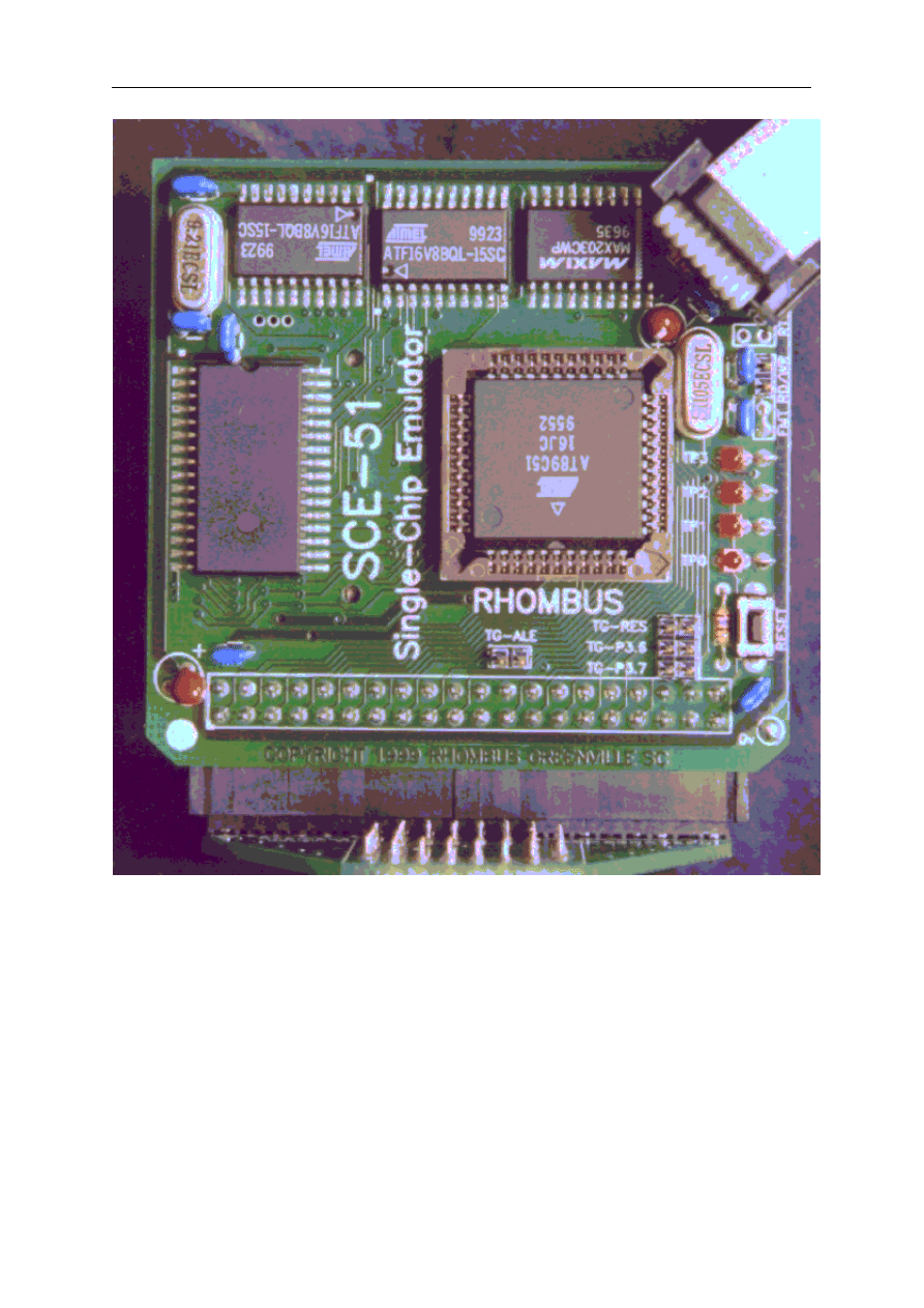
page -282-
© MCS Electronics, 1995-2006
A bootloader is integrated into BASCOM. Select the Rhombus SCE-51 programmer to enable
it.

page -283-
© MCS Electronics, 1995-2006
Index
- # -
#ELSE 63
#ENDIF 64
#IF 62
- $ -
$ASM
$BAUD 72
$BGF 72
$CRYSTAL 74
$DEFAULT XRAM 75
$END ASM 71
$EXTERNAL 75
$INCLUDE 76
$IRAMSTART 77
$LARGE 77
$LCD 78, 80
$LCDRS 79
$LIB 78
$NOBREAK 79
$NOINIT 81
$NONAN 81
$NONULL 118, 82
$NORAMCLEAR 82
$NOSP 83
$OBJ 83
$RAMSIZE 84
$RAMSTART 86
$RAMTRON 84
$REGFILE 87
$ROMSTART 87
$SERIALINPUT 88
$SERIALINPUT2LCD 89
$SERIALOUTPUT 89
$SIM 90
$TIMEOUT 90
$WAIT 91
- 1 -
1WIRE 234
1WIRECOUNT 66
1WREAD 65
1WRESET 65
1WSEARCHFIRST 68

page -284-
© MCS Electronics, 1995-2006
1WSEARCHNEXT 69
1WWRITE 65
- 8 -
8032_Alternative port-pin functions 232
8032_TIMER2 262
80515_WATCHDOG 266
89C51 270
- A -
ABS 92
Additional Hardware 227
ALIAS 91
ASC 93
AT898252 WATCHDOG 265
AVG 94
- B -
BASCOM 20
BASCOM statements 59
BAUD 94
BCD 95
BITWAIT 95
Blow IT Flashprogrammer 241
BREAK 96
BROWSE001e 127
- C -
CALL 97
CASE 196
CHR 98
CLOSE 179
CLS 98
Compiler Limits 256
CONFIG 100
CONFIG 1WIRE 100
CONFIG ADUC812 101
CONFIG BAUD 102
CONFIG BAUD1 102
CONFIG DEBOUNCE 103
CONFIG GETRC 104
CONFIG GRAPHLCD 104
CONFIG I2CDELAY 103
CONFIG LCD 108
CONFIG LCDBUS 109
CONFIG LCDPIN 108
CONFIG MICROWIRE 110
CONFIG PRINT 111
CONFIG SCL 111

page -285-
© MCS Electronics, 1995-2006
CONFIG SDA 112
CONFIG SERVOS 112
CONFIG SPI 113
CONFIG TIMER0, TIMER1 114
CONFIG WATCHDOG 115
CONST 99
COUNTER 116
CPEEK 117
Credits 51
CURSOR 118
CYGNAL JTAG Programmer 246
- D -
DATA 118
DATA EEPROM 265
DEBOUNCE 120
DECLARE 122
DECR 121
DEF 123
DEFBIT 123
DEFBYTE 123
DEFINT 123
DEFLCDCHAR 123
DELAY 124
DIM 124
DISABLE 125
DISPLAY 126
- E -
Edit Copy 24
Edit Cut 24
Edit Find 25
Edit Find Next 25
Edit Goto 26
Edit Indent Block 27
Edit Paste 25
Edit Redo 24
Edit Replace 26
Edit Undo 24
Edit Unindent Block 27
Editor Keys 28
ELSE 127
ENABLE 128
END 128
END IF 129
ERASE 130
Error messages 253
EXIT 131
- F -
File Close 22
File Compile 29

page -286-
© MCS Electronics, 1995-2006
File End 23
File Exit 23
File New 21
File Open 21
File Print 23
File Print Preview 22
File Save 22
File Save As... 22
File Simulate 31
File Transmit 35
FOR 131
FOURTHLINE 132
FUSING 133
Futurelec 246
- G -
GET 134, 179
GETAD 135
GETAD2051 136
GETRC 141
GETRC5 142
GOSUB 144
GOTO 144
Grifo 273, 273
- H -
Hardware - I2C 234
Hardware - LCD display 233
Help About 49
Help Credits 51
Help Forum 51
Help index 50
Help on help 50
Help Shop 50
Help Support 51
HEX 145
HEXVAL 145
HIGH 146
HIGHW 147
HOME 147
- I -
I2C 150
I2CRBYTE 150
I2CRECEIVE 148
I2CSEND 149
I2CSTART 150
I2CSTOP 150
I2CWBYTE 150
IDLE 151
IF 151
INCR 152

page -287-
© MCS Electronics, 1995-2006
INDEX 11
Initialization 226
INKEY 153
INP 154
INPUT 155
INPUTBIN 156
INPUTHEX 157
Installing BASCOM-8051 13
INSTR 158
Internal registers 224
International Resellers 272
INTERRUPTS and PRIORITY 80515 266
INTERRUPTS and PRIORITY 80537 267
- J -
JPK Systems X-programmer 246
- K -
Keyword Reference 11
- L -
Language fundamentals 52
LCASE 159
LCD 160
LCD designer 36
LCDHEX 163
LCDINIT 161
LEFT 163
LEN 164
LIB 37
LOAD 164
LOCATE 165
LOOKUP 166
LOOKUPSTR 167
LOOP 127
LOW 168
LOWERLINE 169
LOWW 168
- M -
MAKEBCD 169
MAKEDEC 170
MAKEINT 170
MAX 171
MCS Flash programmer 238
MCS SPI programmer 240
Microprocessor support 261
MID 172
MIN 172

page -288-
© MCS Electronics, 1995-2006
MOD 173
MWINIT 173
MWREAD 174
MWWOPCODE 175
MWWRITE 176
- N -
NEXT 176
- O -
ON interrupt 177
ON value 178
OPEN 179
Options Communication 43
Options Compiler Communication 40
Options Compiler I2C 41
Options Compiler LCD 42
Options Compiler Misc 42
Options Compiler Output 39
Options Environment 44
Options hardware simulator 47
Options Monitor 47
Options Printer 48
Options Programmer 47
Options View Report 30
OUT 181
- P -
PEEK 182
Peter Averill's TAFE programmer 247
PG2051 flash programmer 241
PG302 programmer 242
POKE 183
PORT 182
POWERDOWN 183
PRINT 184
PRINTBIN 185
PRINTHEX 186
PRIORITY 186
PSET 187
PUT 179, 188
- R -
READ 189
READMAGCARD 190
REM 191
REPLACE 192
Reserved Words 257
RESET 192

page -289-
© MCS Electronics, 1995-2006
RESTORE 193
RETURN 194
Rhombus 281
Rhombus SCE-51 250
RIGHT 194
RND 195
ROTATE 196
RUNNING BASCOM-8051 19
- S -
Sample Electronics ISP programmer 244
SE 512 or SE514 programmer 243
SE-812 243
SE511-SE516 programmer 251
SELECT 196
Send to chip 34
SET 197
SHIFT 198
SHIFTCURSOR 198
SHIFTIN 199
SHIFTLCD 200
SHOWPIC 201
SOUND 201
SPACE 202
SPC 203
SPIIN 203
SPIINIT 204
SPIOUT 205
START 205
STK200/300 ISP Programmer 248
STOP 206
STOP TIMER 206
STR 208
STRING 208
SUB 209
SWAP 210
Syntax check 30
- T -
THIRDLINE 210
Tool LIB Manager 37
Tool Triscent Converter 39
Tools Export to RTF 39
Tools Graphic Converter 36
- U -
UCASE 211
UPPERLINE 212
Using assemly 217
Using the DAC 268

page -290-
© MCS Electronics, 1995-2006
- V -
VAL 212
VARPTR 213
- W -
WAIT 213
WAITKEY 214
WAITMS 214
WATCHDOG 215
WEND 216
WHILE 216
WHILE.. WEND 216
Window arrange icons 49
Window cascade 49
Window tile 49
Windows minimize all 49

page -291-
© MCS Electronics, 1995-2006
© MCS Electronics, 1995-2006
www.mcselec.com
Making Things Easy
Document Outline
- Table of Contents
- INDEX
- Installing BASCOM-8051
- BASCOM IDE
- RUNNING BASCOM-8051
- BASCOM IDE
- File New
- File Open
- File Close
- File Save
- File Save As...
- File Print Preview
- File Print
- File Exit
- Edit Undo
- Edit Redo
- Edit Copy
- Edit Cut
- Edit Paste
- Edit Find
- Edit Find Next
- Edit Replace
- Edit Goto
- Edit Indent Block
- Edit Unindent Block
- Editor Keys
- Program Compile
- Program Syntax check
- Program Show Result
- Program Simulate
- Program Send to chip
- Tools Terminal Emulator
- Tools LCD designer
- Tools Graphic Converter
- Tools LIB Manager
- Tools Triscent Converter
- Tools Export to RTF
- Options Compiler Output
- Options Compiler Communication
- Options Compiler I2C
- Options Compiler LCD
- Options Compiler Misc
- Options Communication
- Options Environment
- Options hardware simulator
- Options Programmer
- Options Monitor
- Options Printer
- Window cascade
- Window Tile
- Window arrange icons
- Window minimize all
- Help About
- Help Index
- Help on help
- Help Shop
- Help Forum
- Help Support
- Help Credits
- Language fundamentals
- BASCOM Language Reference
- BASCOM Statements
- #IF
- #ELSE
- #ENDIF
- 1WIRE
- 1WIRECOUNT
- 1WSEARCHFIRST
- 1WSEARCHNEXT
- $ASM - $END ASM
- $BAUD
- $BGF
- $CRYSTAL
- $DEFAULT XRAM
- $EXTERNAL
- $INCLUDE
- $IRAMSTART
- $LARGE
- $LIB
- $LCD
- $LCDRS
- $MAP
- $NOBREAK
- $NOINIT
- $NONAN
- $NONULL
- $NORAMCLEAR
- $NOSP
- $OBJ
- $RAMSIZE
- $RAMTRON
- $RAMSTART
- $REGFILE
- $ROMSTART
- $SERIALINPUT
- $SERIALINPUT2LCD
- $SERIALOUTPUT
- $SIM
- $TIMEOUT
- $WAIT
- ALIAS
- ABS
- ASC
- AVG
- BAUD
- BCD
- BITWAIT
- BREAK
- CALL
- CHR
- CLS
- CONST
- CONFIG
- CONFIG 1WIRE
- CONFIG ADUC812
- CONFIG BAUD
- CONFIG BAUD1
- CONFIG DEBOUNCE
- CONFIG I2CDELAY
- CONFIG GETRC
- CONFIG GRAPHLCD
- CONFIG LCDPIN
- CONFIG LCD
- CONFIG LCDBUS
- CONFIG MICROWIRE
- CONFIG PRINT
- CONFIG SCL
- CONFIG SDA
- CONFIG SERVOS
- CONFIG SPI
- CONFIG TIMER0, TIMER1
- CONFIG WATCHDOG
- COUNTER
- CPEEK
- CURSOR
- DATA
- DEBOUNCE
- DECR
- DECLARE
- DEF
- DEFLCDCHAR
- DELAY
- DIM
- DISABLE
- DISPLAY
- DO
- ELSE
- ENABLE
- END
- END IF
- ERASE
- EXIT
- FOR
- FOURTHLINE
- FUSING
- GET
- GETAD
- GETAD2051
- GETRC
- GETRC5
- GOSUB
- GOTO
- HEX
- HEXVAL
- HIGH
- HIGHW
- HOME
- I2CRECEIVE
- I2CSEND
- I2C
- IDLE
- IF
- INCR
- INKEY
- INP
- INPUT
- INPUTBIN
- INPUTHEX
- INSTR
- LCASE
- LCD
- LCDINIT
- LCDHEX
- LEFT
- LEN
- LOAD
- LOCATE
- LOOKUP
- LOOKUPSTR
- LOW
- LOWW
- LOWERLINE
- MAKEBCD
- MAKEDEC
- MAKEINT
- MAX
- MID
- MIN
- MOD
- MWINIT
- MWREAD
- MWWOPCODE
- MWWRITE
- NEXT
- ON interrupt
- ON value
- OPEN
- OUT
- PORT
- PEEK
- POKE
- POWERDOWN
- PRINTBIN
- PRINTHEX
- PRIORITY
- PSET
- PUT
- READ
- READMAGCARD
- REM
- REPLACE
- RESET
- RESTORE
- RETURN
- RIGHT
- RND
- ROTATE
- SELECT
- SET
- SHIFTCURSOR
- SHIFT
- SHIFTIN
- SHIFTLCD
- SHOWPIC
- SOUND
- SPACE
- SPC
- SPIIN
- SPIINIT
- SPIOUT
- START
- STOP
- STOP Timer
- STR
- STRING
- SUB
- SWAP
- THIRDLINE
- UCASE
- UPPERLINE
- VAL
- VARPTR
- WAIT
- WAITKEY
- WAITMS
- WATCHDOG
- WHILE .. WEND
- Using assembly
- Additional Hardware
- Supported Programmers
- MCS Flash programmer
- MCS SPI programmer
- Blow IT Flashprogrammer
- PG2051 flash programmer
- PG302 programmer
- SE512 or SE514 programmer
- SE-812
- Sample Electronics ISP programmer
- CYGNAL JTAG Programmer
- Futurelec
- JPK Systems X-programmer
- Peter Averill's TAFE programmer
- STK200/300 ISP Programmer
- Rhombus SCE-51
- SE511-SE516 programmer
- BASCOM Misc
- Microprocessor support
- International Resellers
- Third party hardware
Wyszukiwarka
Podobne podstrony:
Bascom 04
Bascom College wykład 7
AVT2500 Płytka Testowa Dla Bascom
Bascom - podstawy, Nauka
Bascom College wyklad 9 id 80490
z80 wersja polska, ELEKTRONIKA I PROGRAMOWANIE, Mikroprocesory, programowanie Bascom, AVR,
BASCOM
z80 porownanie list, ELEKTRONIKA I PROGRAMOWANIE, Mikroprocesory, programowanie Bascom, AVR,
opis pojec, ELEKTRONIKA I PROGRAMOWANIE, Mikroprocesory, programowanie Bascom, AVR,
Bascom 03
bascom 8051 kotlhvni2l5w3emcxjq Nieznany (2)
opis wyprowadzen, ELEKTRONIKA I PROGRAMOWANIE, Mikroprocesory, programowanie Bascom, AVR,
Bascom 05
BASCOM
bascom, Mikrokontrolery
bascom komendy
mikrokontrolery, ELEKTRONIKA I PROGRAMOWANIE, Mikroprocesory, programowanie Bascom, AVR,
8051 lista rozkazow, ELEKTRONIKA I PROGRAMOWANIE, Mikroprocesory, programowanie Bascom, AVR,
Programowanie w C i ASM programatorem BASCOM
więcej podobnych podstron