
BASCOM-8051 Version 2.00
Page -1-
BASCOM-8051
The Windows 8051 BASIC Compiler
BASCOM-8051 User Guide
© 1995-2000 MCS Electronics

BASCOM-8051 Version 2.00
Page -2-
MCS Electronics may update this documentation without notice.
Products specification and usage may change accordingly.
MCS Electronics will not be liable for any mis information or errors found in this
document.
All software provided with this product package is provided ' AS IS' without any
warranty expressed or implied.
MCS Electronics will not be liable for any damages, costs or loss of profits arising
from the usage of this product package.
No part of this document may be reproduced or transmitted in any form or by any
means, Electronics or mechanical, including photocopying and recording, for any
purpose without written permission of MCS Electronics.
© MCS Electronics. All rights reserved.
Thank you for using BASCOM-8051, the Windows BASIC compiler for the
AT89C2051 and other 8051 family members.
This guide will help you to install BASCOM and explains the environment briefly.
If you have questions, remarks or suggestions please let us know.
You can contact us by sending an Email to 8051@mcselec.com
Our website is at http://www.mcselec.com
For info on updates : please read the readme.txt file installed into the BASCOM
directory !!!
Regards,
Mark Alberts
MCS Electronics
BASCOM-8051 Version 2.00
Page -3-
Installing BASCOM-8051
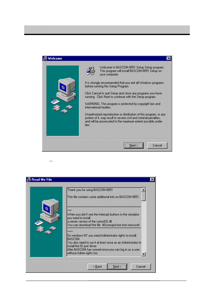
In the program manager from Windows, select File, Run, and then type A:SETUP
↵
↵↵
↵
.
The following window will appear:
Click on the Next-button to continue installation.
The following window with useful information will appear :
This info is also stored in the readme.txt file.
BASCOM-8051 Version 2.00
Page -4-
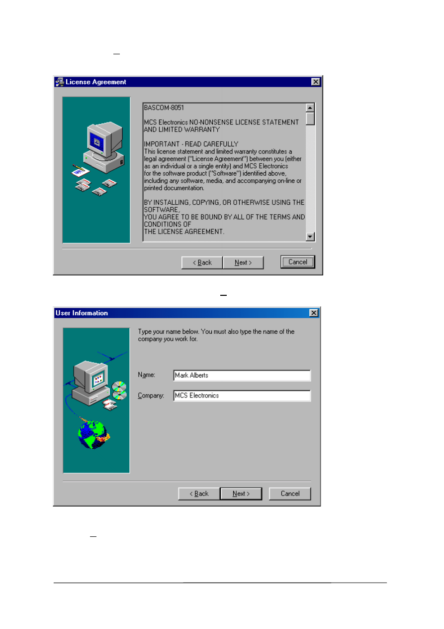
Again click the Next button.
Now a window with license information will be shown:
Read the license agreement and click the Next-button
Now fill in your name and company name.
Click the Next-button to continue.
BASCOM-8051 Version 2.00
Page -5-
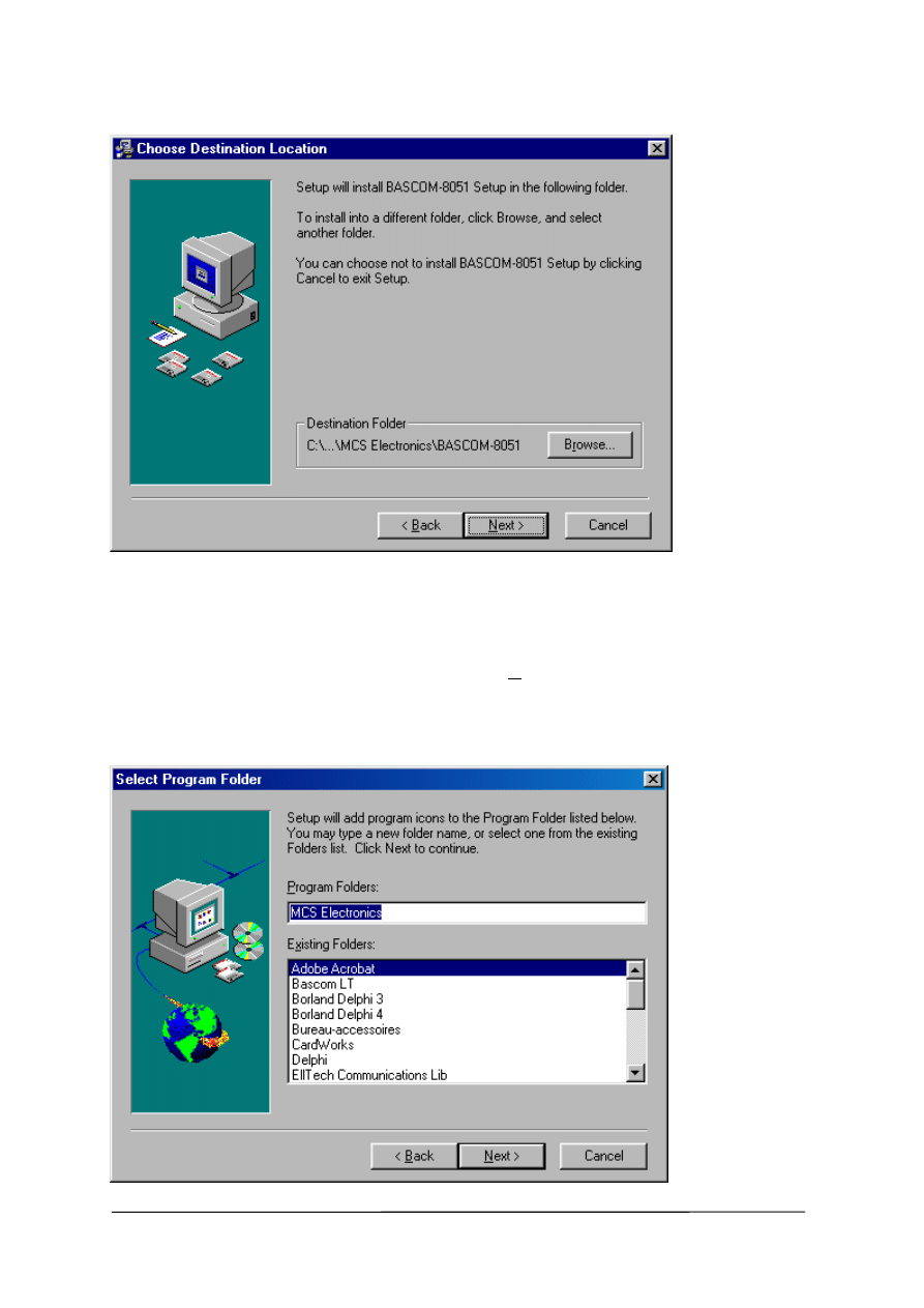
Now you have the change to select the directory in which BASCOM will be installed.
Select the Browse-button to change the directory path if required.
By default BASCOM-8051 will be installed into
C:\Program Files\MCS Electronics\BASCOM-8051
After selecting the installation directory click the Next-button.
Now you will be asked in which program group the BASCOM-8051-icon must be
placed. By default a new program group named MCS Electronics\BASCOM-8051
will be made.
BASCOM-8051 Version 2.00
Page -6-
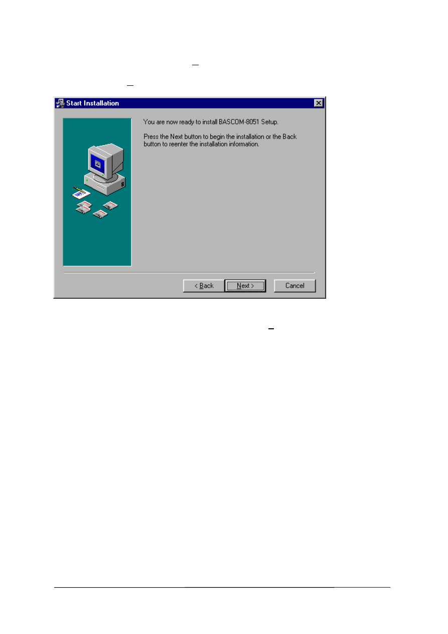
After selecting the group, click the Next-button to continue.
A summary will be showed and you have the change to go back to change your
settings. Click the Next-button to install BASCOM-8051.
When the installation is completed you must click the Finish-button, and restart
Windows.
A sub directory named SAMPLES contains all the BASCOM-8051 sample files.
********************IMPORTANT ********************
The license file must be in the same directory as the SETUP.EXE. It will be copied
into the BASCOM application directory. This only applies when you buy from an
internet vendor.
The default path for a BASCOM installation is :
C:\Program Files\MCS Electronics\BASCOM-8051\
When you install on NT you must have administrator rights during installation and the
first time you run BASCOM. This will install the ioport.sys driver.
After this you may login as a normal user too.
BASCOM-8051 Version 2.00
Page -7-
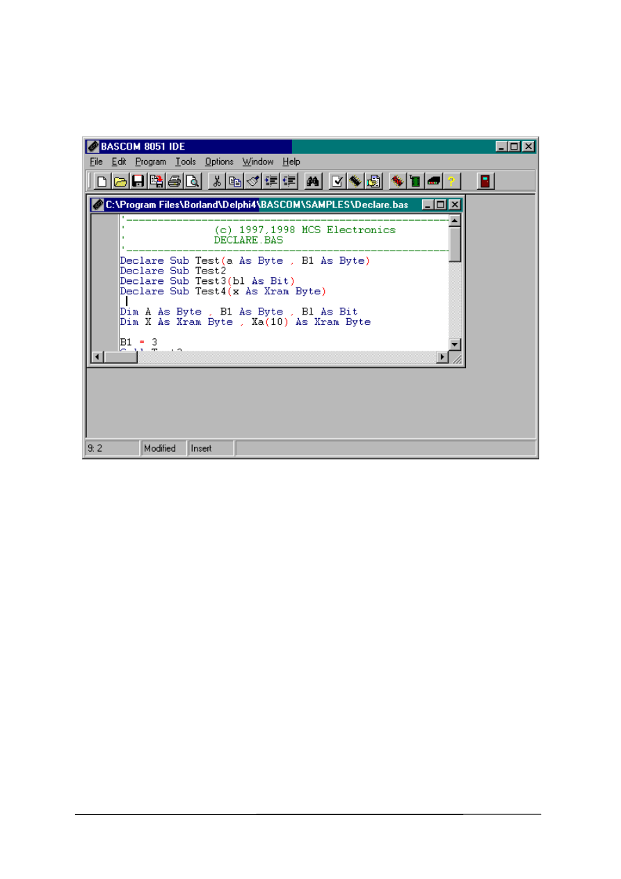
RUNNING BASCOM-8051
Double-click the BASCOM-8051 icon to run BASCOM.
The following window will appear. (or an empty edit window on your first run)
The last opened file will be loaded.
The menu options are described on the following pages.
BASCOM-8051 Version 2.00
Page -8-
File New
This option creates a new window in which you write your program.
The focus is set to the new window.
File new shortcut :
, CTRL + N
File Open
With this option you can load an existing program from disk.
BASCOM saves files in standard ASCII format. So if you want to load a file which is
made with another editor be sure that it is saved as an ASCII file.
Note that you can specify that BASCOM must reformat the file when it opens it with
the Options Environment option. This should only be necessary when loading files
made with another editor.
File open shortcut :
, CTRL+O
File Close
Closes the current program.
When you have made changes to the program you will be asked to save the program
first.
File close shortcut :
File Save
With this option you can quick save your current program to disk.
If the program was created with the File New option you will be asked to name the
file first. Use the File Save As option to give the file another name.
Note that the file is saved as an ASCII file.
File save shortcut :
, CTRL+S
BASCOM-8051 Version 2.00
Page -9-
File Save As...
With this option you can save your current program to disk.
You can enter a different name before the program is saved.
Note that the file is saved as an ASCII file.
File save as shortcut :
File Print Preview
With this option you can preview the current program before it is printed.
Note that the current program is the program which has the focus.
File print preview shortcut :
File Print
With this option you can print the current program.
Note that the current program is the program which has the focus.
File print shortcut :
, CTRL+P
File Exit
With this option you can leave BASCOM.
If you have made changes to your program, you can save them upon leaving
BASCOM.
File exit shortcut :
BASCOM-8051 Version 2.00
Page -10-
Edit Undo
With this option you can undo the last textmanupulation.
Edit Undo shortcut :
, CTRL+Z
Edit Redo
With this option you can redo the last undo.
Edit Redo shortcut :
, CTRL+SHIFT+Z
Edit Cut
With this option you can cut selected text into the clipboard.
Edit cut shortcut :
, CTRL+X
Edit Copy
With this option you can copy selected text into the clipboard.
Edit copy shortcut :
, CTRL+C
Edit Paste
With this option you can paste text from the clipboard into the current cursor position.
Edit paste shortcut :
, CTRL+V
Edit Find
With this option you can search for text in your program.
Text at the cursorposition will be placed in the find dialog box.
Edit Find shortcut :
, CTRL+F
BASCOM-8051 Version 2.00
Page -11-
Edit Find Next
With this option you can search for the last specified search item.
Edit Find Next shortcut :
, F3
Edit Replace
With this option you can replace text in your program.
Edit Replace shortcut :
, CTRL+R
Edit Goto
With this option you can goto a line immediately.
Edit goto line shortcut :
,CTRL+G
Edit Toggle Bookmark
With this option you can set/reset a bookmark, so you can jump in your code with
the Edit Goto Bookmark option. Shortcut : CTRL+K + x where x can be 1-8
Edit Goto Bookmark
With this option you can jump to a bookmark.
The can be up to 8 bookmarks. Shortcut : CTRL+Q+ x where x can be 1-8
Edit Indent Block
With this option you can indent a selected block of text.
Edit Indent Block shortcut :
, CTRL+SHIFT+I
BASCOM-8051 Version 2.00
Page -12-
Edit Unindent Block
With this option you can unindent a block.
Edit Unindent Block shortcut :
, CTRL+SHIFT+U
Program Compile
With this option you can compile your current program.
Your program will be saved automatically before it will be compiled.
The following files will be created depending on the Option Compiler Settings.
File
xxx.BIN
Binary file which can be programmed into the uP.
xxx.DBG Debug file which is needed by the simulator.
xxx.HEX Intel
hexadecimal file which is needed by some programmers.
xxx.ERR
Error file. (only when errors are found)
xxx.RPT Report file.
If an error occurs, you will receive an error message.
After you have pressed the Ok-button the cursor will be set to the line in which the
error occurred. The margin will also display a
sign.
Program compile shortcut :
, F7
Program Syntax Check
With this option your program is checked for syntax errors. No file will be created
except for an error file, if an error is found.
Program syntaxcheck shortcut
, CTRL + F7
Program Show result
Use this option to view the result of the compilation.
See the Options Compiler Output for specifying which files must be created.
The files that can be viewed are report and error.
File show result shortcut :
,CTRL+W
BASCOM-8051 Version 2.00
Page -13-
Information provided in the report:
Info
Description
Compiler
The version of the compiler.
Processor
The selected targetprocessor.(dat file)
Date and time
The compilation date and time.
Baud timer
The timer used for generating the baudrate. 0 when no timer is
used.
Baudrate and
frequency
The baudrate selected for the uP and the used crystal. This info
is used for RS232 related statements such as PRINT and
INPUT. Note that when you use the $crystal and $baud
statements the exact baudrate is shown.
ROM start
The starting location of the ROM code. Default 0.
RAM start
The starting location of the external RAM space. Default 0.
LCD mode
The mode the LCD display is used. 4 bit mode or 8 bit mode.
Stack start
The starting location of the stack. The space below the stack is
used for variables. The stack grows when calls are made by the
machine language routines.
Used ROM
Displays the length of the generated binary file.
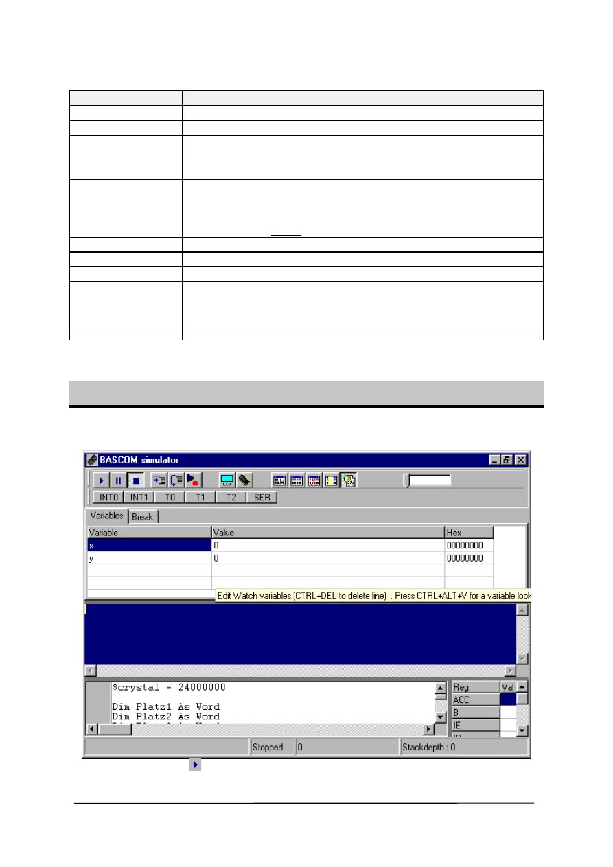
Program Simulate
With this option you can simulate your program.
The simulator window looks like this:
Click the Run-button
to start the simulation.
The output (if any) is displayed in the middle blue colored section.
BASCOM-8051 Version 2.00
Page -14-
If input is required than you must set the focus to that section before entering the
input. This only applies to PRINT and INPUT related statements.
To pause simulation, click the Pause-button
. Click the run-button again to
continue.
Click the Stop-button
to stop execution.
Click the Step-button
to step through the program.
Click the Step over-button
to step over SUBS (GOSUB and CALL).
Select a line in the source window and click the run to-button
to run the program
till the selected line. The simulator will pause at that point.
To watch the value of a variable, move the mousecursor over the variable name.
The value is displayed in the statusbar.
To add a variable to the watch window, select it and press return, or type it’s name
in the watch window.
To alter the value of a variable set the focus to the value and change the value.
The INT0, INT1, T0, T1 and SER button can be clicked to generate an interrupt.
Because this is a software emulator no hardware interrupts can be generated. You
have to do this yourself by clicking these buttons. The TIMER interrupt is simulated.
Additional buttons can be displayed when the chip has additional interrupts.
Press the hardware simulation button
to enable the hardware simulation.
You need additional hardware to use this future.
An application note can be downloaded that describes the hardware that is needed.
The hardware simulator will simulate port 1 and 3.
This way you can test your program in circuit without programming the device.
At the moment only the status reading and setting of the ports is supported.
This means that interrupts are not yet supported in hardware simulation.
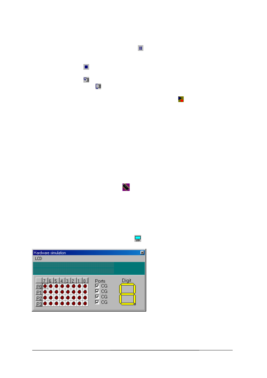
By clicking the hardware simulation button
, the following window is displayed.
The upper section emulates a LCD display. Select the proper type from the menu.
The lower section emulates port 0-3 and a LED display.
By clicking on the LEDS, you can switch them on or off.
BASCOM-8051 Version 2.00
Page -15-
By right clicking on the LED display, you can define to which port pins the segments
are connected.
On the right side of the code window, the SFR’s are displayed. You can alter them
just like the normal variables.
During simulation you can set breakpoints by pressing F9. A breakpoint can only be
set on a line which contains executable code. This is notated by a small yellow dot.
When a breakpoint is selected, a red dot is displayed.
A blue arrow shows the line executing.
Program Simulate shortcut :
, F2
Program Send to chip
This option will bring up the selected programmer or will program the chip directly if
this options is selected from the Programmer options.
Program send to chip shortcut
, F4
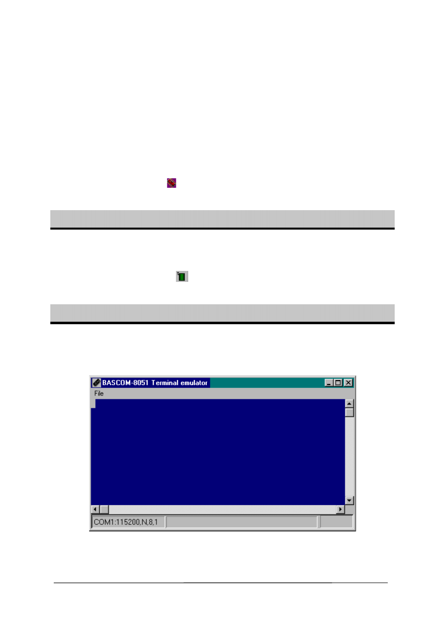
Tools Terminal Emulator
With this option you can communicate via the RS-232 interface to the
microcomputer. The following window will appear :
Information you type and information that the computer board sends, are displayed
in the same window.
BASCOM-8051 Version 2.00
Page -16-
Note that you must use the same baud rate at both sides. If you compiled your
program with the Compiler Settings at 4800 baud, you must set the Communication
Settings also to 4800 baud. The setting for the baud rate is also reported in the
report file.
File Upload
Uploads the current program in HEX format. This option is meant for
loading the program into a monitor program.
File Escape
Aborts the upload to the monitor program.
File Exit
Closes terminal emulator.
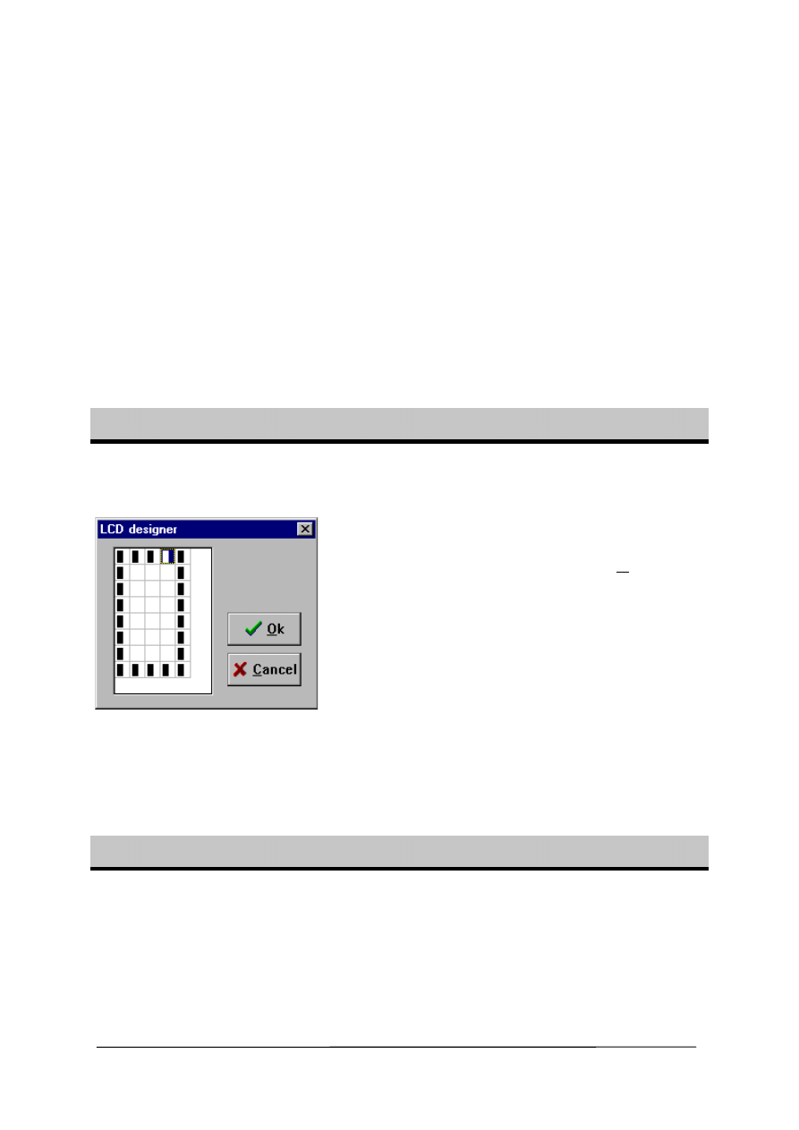
Tools LCD designer
With this option you can design special characters for LCD-displays.
The following window will appear:
The LCD-matrix has 7x5 points. The
bottom row is reserved for the cursor
but can be used. You can select a
point by double-clicking the left
mousebutton. If a cell was selected it
will be deselected. When you are
finished you can press the Ok-button :
a statement will be inserted in your
active program-editor window at the
current cursorposition. The statement
looks like this :
Deflcdchar ?,1,2,3,4,5,6,7,8
You must replace the ?-sign with a
character number ranging from 0-7.
See Deflcdchar in the helpfile.
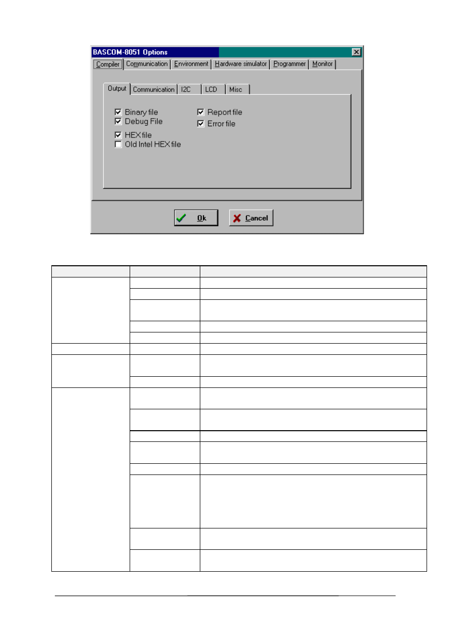
Options Compiler
With this option you can modify the compiler options.
BASCOM-8051 Version 2.00
Page -17-
The following options are available (by selecting the specified tab):
TAB
OPTION
DESCRIPTION
Output
Binary file
Generates a binary file.
HEX file
Generates an Intel Hexadecimal file.
DEBUG file
Generates a debug and map file needed by the
simulator.
Report file
Generates a report file.
Error file
Generates an error file if an error occurs.
Old Intel Hex
Generates an old Intel hex file use by some monitors.
Communication Baudrate
The baudrate that the RS232 routines like PRINT and
INPUT uses to communicate with your computer.
Frequency
The frequency of the uP crystal on you uP-board.
I2C
SCL port
The pin that is used for the SCL-line needed by the
I2C routines.
SDA port
The pin that is used for the SDA-line needed by the
I2C routines.
RC5 port
The pin that is used for the GETRC5 statement.
LCD
DB4-DB7,
ENABLE, RS
The port pins that are connected to the LCD display.
MISC
Register file
The name of the SFR register file.
Byte End
The last position in RAM that can be used for internal
variables. The stack will start at ByteEnd + 1.
When you run out of stack space you must decrease
this value, this also means that there is less space for
variables.
Size warning
Size of ROM code that is allowed. Bigger code will
give a warning.
Compiler
Select the BASCOM-8051 or the BASCOM LT
compatibility compiler.
BASCOM-8051 Version 2.00
Page -18-
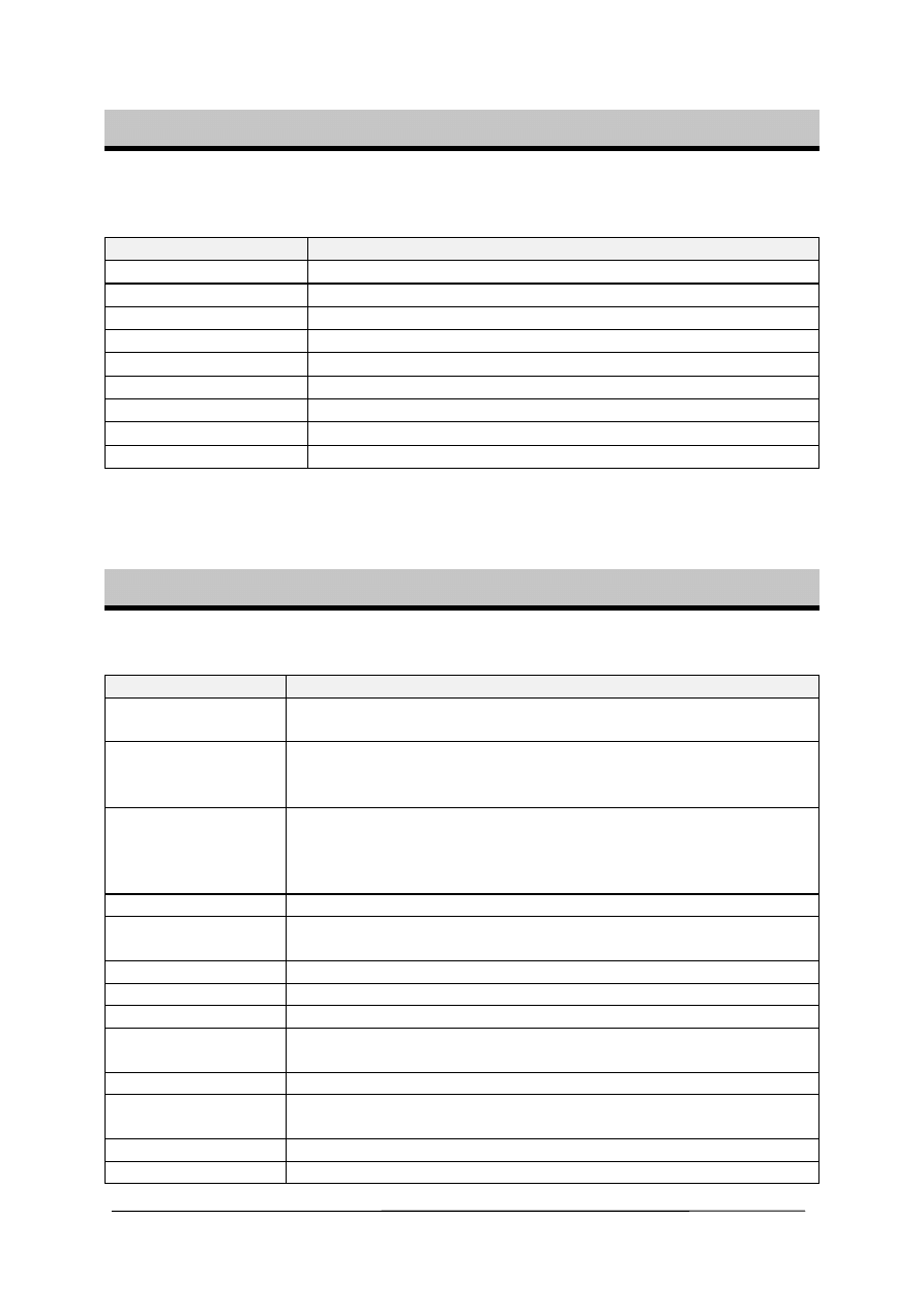
Options Communication
With this option you can modify the communication settings for the terminal
emulator.
Item
Description
Comport
The comport of your PC to use.
Baudrate
The baudrate to use.
Parity
Parity, default None.
Databits
Number of databits, default 8.
Stopbits
Number of stopbits, default 1.
Handshake
Handshake used, default none.
Emulation
Emulation used, default BBS ANSI.
Font
Font type and color used by the emulator.
Backcolor
Backgroundcolor of the terminal emulator.
Note that the baudrate of the terminal emulator and the baudrate setting of the
compiler options, must be the same in order to work correctly.
Options Environment
With this option you can modify the environment options.
OPTION
DESCRIPTION
Auto Indent
When you press return, the cursor is set to the next line at the
current column position
Don’t change case
When set, the reformatter won’t change the case of the text.
Default the text is reformatted so every word begins in
uppercase.
Reformat BAS files
Reformat files when loading them into the editor.
This is only necessary when you are loading files that where
created with another editor. Normally you won’t need to set this
option.
Reformat code
Reformat code when entered in the editor.
Smart TAB
When set, a TAB will go to the column where text starts on the
previous line.
Syntax highlighting
This options highlights BASCOM statements in the editor.
Tooltips Show
tooltips.
Show toolbar
Shows the toolbar with the shortcut icons.
Size of new editor
window
When a new editor window is created you can select how it will
be made. Normal or Maximized (full window)
Editor font
Click on this label to select another font for the editor window.
Comment
The position of the comment. Comment is positioned at the
right of your source code.
TAB-size
Number of spaces that are generated for a TAB.
Background color
The backgroundcolor of the editor window.

BASCOM-8051 Version 2.00
Page -19-
Keymapping
Choose default, Classic, Brief or Epsilon.
No reformat
extension
File extensions separated by a space that will not be
reformatted when loaded.
Options Hardware Simulator
With this option you can modify the hardware simulator settings.
OPTION
DESCRIPTION
Simulator LPT
Portaddress of the printer port that is attached to the sim.
Simulator delay
Delay for the simulator in milli seconds. For fast PC’s only.
Options Programmer
With this option you can modify the programmer settings.
OPTION
DESCRIPTION
Programmer
Select one from the list.
Auto flash
Some programmers support auto flash. Pressing F4 will
program the chip without showing the programmer window.
Auto verify
Some programmers support verifying. The chipcontent will be
verified after programming.
LPT address
Port address of the LPT that is connected to the programmer.
Port delay
Delay, only for Blow IT programmer.
PCF8574A
Only for MCS Flashprogrammer or simulator. Select when you
use these chips instead of the PCF8574.
Send HEX
Only for EPROM Simulator on LPT. Select when a HEX file
must be sent instead of the bin file.
Options Monitor
With this option you can modify the monitor settings.
OPTION
DESCRIPTION
Monitor
Select the monitor program used.
Other
Will shell to a external program. Of course it must accept the
filename as a parameter.
Options Printer
With this option you can modify the printer settings.

BASCOM-8051 Version 2.00
Page -20-
OPTION
DESCRIPTION
Left
The left margin.
Right
The right margin.
Top
The top margin.
Bottom
The bottom margin.
Window Cascade
Cascade all open editor windows.
Window Tile
Tile all open editor windows.
Window Arrange icons
Arrange the icons of the minimized editor windows.
Window Minimize all
Minimize all open editor windows.
BASCOM-8051 Version 2.00
Page -21-
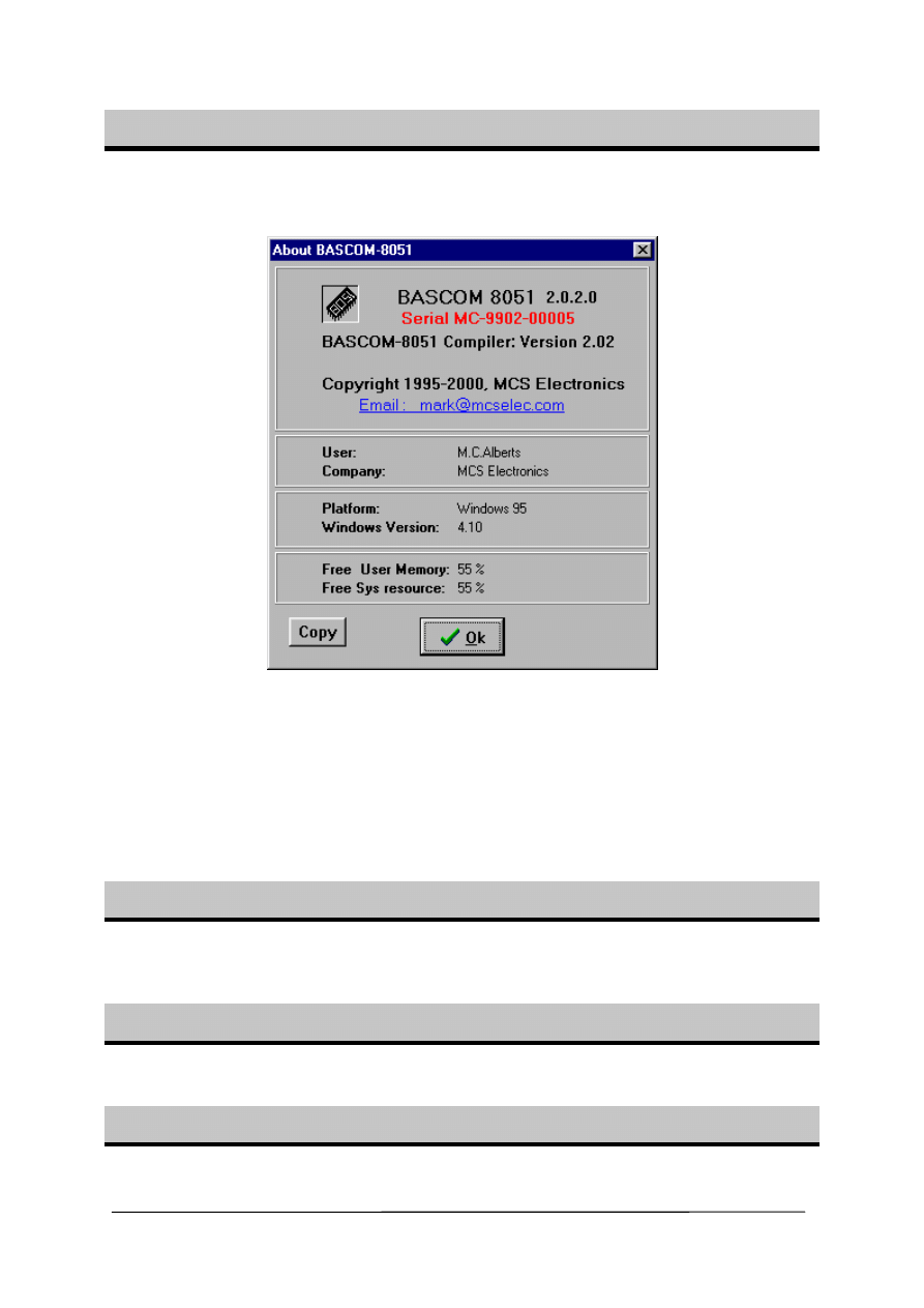
Help About
This option shows an about box as showed below.
Your serialnumber is shown in the about box.
You will need this when you have questions about the product.
The library version is also shown. In this case it is 2.02.
You can compare it with the one on our website in case you need an update.
By clicking the Copy-button you can copy the version details to the clipboard.
This is useful when you have a question about BASCOM.
Click on Ok to return to the editor.
Help Index
Brings up the BASCOM help file.
When you are editing, the current word will be used as a keyword.
Help on help
Shows help on how to use the Windows help system.
Help Credits
Shows a form with credits to people I like to thank for their contributions to BASCOM.

BASCOM-8051 Version 2.00
Page -22-
Editor Keys
Key
Action
LEFT ARROW
One character to the left
RIGHT ARROW
One character to the right
UP ARROW
One line up
DOWN ARROW
One line down
HOME
To the beginning of a line
END
To the end of a line
PAGE UP
Up one window
PAGE DOWN
Down one window
CTRL+LEFT
One word to the left
CTRL+RIGHT
One word to the right
CTRL+HOME
To the start of the text
CTRL+END
To the end of the text
CTRL+ Y
Delete current line
INS
Toggles insert/overstrike mode
F1
Help (context sensitive)
F3
Find next text
CTRL+O
Load File
CTRL+S
Save File
F7
Compile File
CTRL+P
Print File
CTRL+T
Terminal emulator
CTRL+M
File Simulation
CTRL+A
Flash programmer
CTRL+F
Find text
CTRL+P
Compiler Options
CTRL+W
Show result of compilation
CTRL+X
Cut selected text into clipboard
CTRL+INS
Copy selected text into clipboard
SHIFT+INS
Copy text from clipboard into editor
Select text
Hold the SHIFT key down and use the cursor keys to select text.
or keep the left mouse key pressed and tag the cursor over the
text to select.

BASCOM-8051 Version 2.00
Page -23-
Developing order
•
start BASCOM;
•
open a file or create a new one;
•
check the baudrate and frequency settings for the target system;
•
compile the file;
•
if an error occurs fix it and recompile (F7);
•
run the simulator and check if you don’t run out of stack space;
•
program the chip;
Memory
Every variable uses memory.
The available memory is 128 bytes. (or 256 bytes for some chips)
From these 128 bytes a maximum of 32 are used for internal registers.
Some bytes are used by the stack. This depends on the statements you have used.
Each 8 used bits occupy 1 byte.
Each byte occupy 1 byte.
Each integer/word occupies 2 bytes.
Each Long/Single occupies 4 bytes.
Use bytes when you can. (not allowed for negative values)
If your program use less than 64 bytes you can use an 89C1051 as well. This chip
only doesn’t have an UART for PRINT and INPUT statements.
You can also add external memory when you run out of variable space.

BASCOM-8051 Version 2.00
Page -24-
Error codes
The following table lists errors that can occur.
Nr
Error
message
1
BASIC sourcefile not found
2
Code does not fit into FLASHROM
3 Unknown
statement
4 Extension
expected
5
Wrong variable or variable not dimensioned
6
Two parameters expected
7
No more space for BIT
8
No more space for BYTE
9
No more space for INTEGER
10
Wrong type (BIT,BYTE or INTEGER) expected
11
AS expected by DIM
12
,
expected
13
Unknown
interrupt
14
IF THEN expected
15
FOR, DO or WHILE expected
16
Wrong number of parameters
17
Illegal compare (=,>,<,<>,<=,>=) expected
18
THEN
expected
19
TIMER0 or TIMER1 expected
20
DO
expected
21
UNTIL
expected
22
Illegal mathematical operation
23
FOR
expected
24
WHILE
expected
25
Variable not dimensioned
26
Source file not found
27
Label not found
100-134
These are internal assembler warnings. Contact MCS Electronics .
135
Too many RAM used
136
Variable already dimensioned
137
Constant must be in range of 1-8
138
Baudrate not supported with selected frequency
139
9 parameters expected
140
COUNTER0 or COUNTER1 expected.
141
=
expected.
142
Maximum of 128 ALIAS statement allowed.
143
Duplicate
label
144
Value does not fit into byte(byte can store 0-255)
BASCOM-8051 Version 2.00
Page -25-
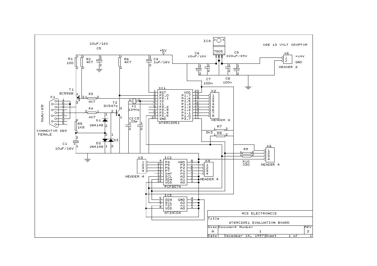
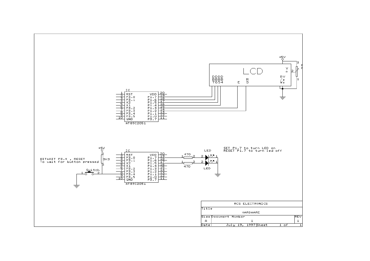
Hardware
You can attach additional hardware to the ports of the microprocessor.
The following statements will become available :
I2CSEND and I2CRECEIVE and other I2C related statements.
LCD, LCDHEX, DISPLAY and other related LCD-statements.
See the compiler settings for selecting the SDA (data) and SCL(clock) pins.
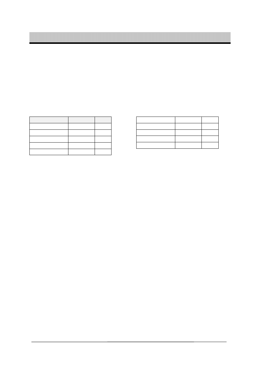
The LCD-display must be connected as following:
LCD-DISPLAY PORT
PIN
DB7 P1.7
14
DB6 P1.6
13
DB5 P1.5
12
DB4 P1.4
11
E P1.3
6
RS P1.2
4
RW Ground
5
Vss Ground
1
Vdd +5
Volt
2
Vo 0-5
Volt
3
This leaves P1.1 and P1.0 and P3 for other purposes.
You can change these settings from the Options LCD menu.
The LCD-display operates in 4-bit mode.
BASCOM supports a lot of statements to control the LCD-display.
For those who want to have more control the example below shows how to.
Acc = 5
‘load register A with value
Call Lcd_control
‘it is a control value to control the display
Acc = 65
‘load with new value (letter A)
Call Write_lcd
‘write it to the LCD-display
Note that lcd_control and write_lcd are assembler subroutines which can be called
from BASCOM.
See manufacture details from your LCD display for the correct assignment.
BASCOM-8051 Version 2.00
Page -26-
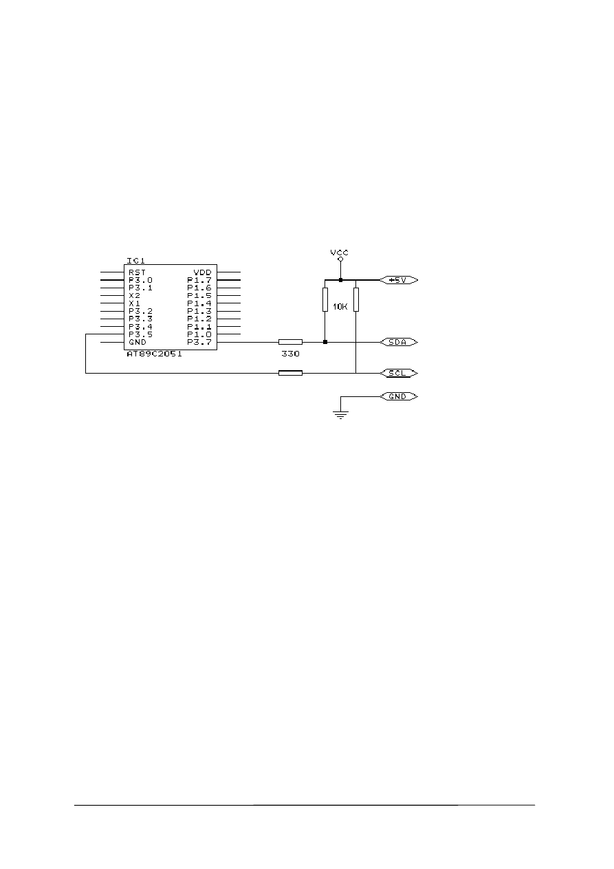
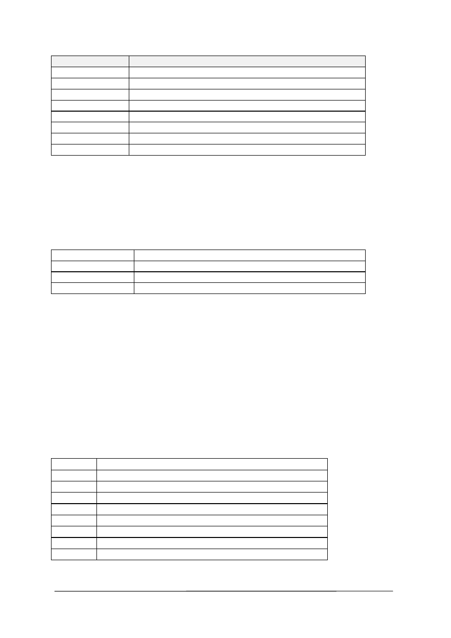
I2C
The design below shows how to implement an I2C-bus.
R1 and R2 are 330 ohm resistors.
R3 and R4 are 10 kilo-ohm resistors.
Note that you can select which port pins you want to use for the I2C interface with
the compiler settings.
A PCB board with RS-232 interface, I2C interface, EEPROM 2404 and I/O expander
PCF8574 is also available. Please inform for prices.
Hardware related commands
The uP must be connected to a crystal. The frequency of the crystal can range from
0 to 24 Mhz (for AT89Cx051).
The frequency is divided by 12 internally. So with a 12 Mhz crystal the processor is
clocked with 1 Mhz.
Because almost each instruction takes 1 clockcycle to execute the processor can
handle 1 MIPS.
When RS-232 statements such as INKEY, PRINT and INPUT are used, TIMER1 is
connected to the systemclock. So TIMER1 can’t be used for other purposes such as
ON TIMER1 anymore. When no RS-232 related statements are used you can use
TIMER1.
The Baudrate is generated by dividing the systemclock. When a crystal of 11.0592
Mhz is used, the Baudrate can be generated very accurately. Other crystals can be
used also but the generated baudrate will never be exactly 2400 or 4800 baud and
higher baudrates are almost impossible. Use the $BAUD = xx and $CRYSTAL = xx
statements to specify your own settings. The exact baudrate will be shown in the
report.
BASCOM-8051 Version 2.00
Page -27-
Clock
The clockfrequency is the systemfrequency divided by 12. With a 12 Mhz crystal this
means that every microsecond the register is incremented.
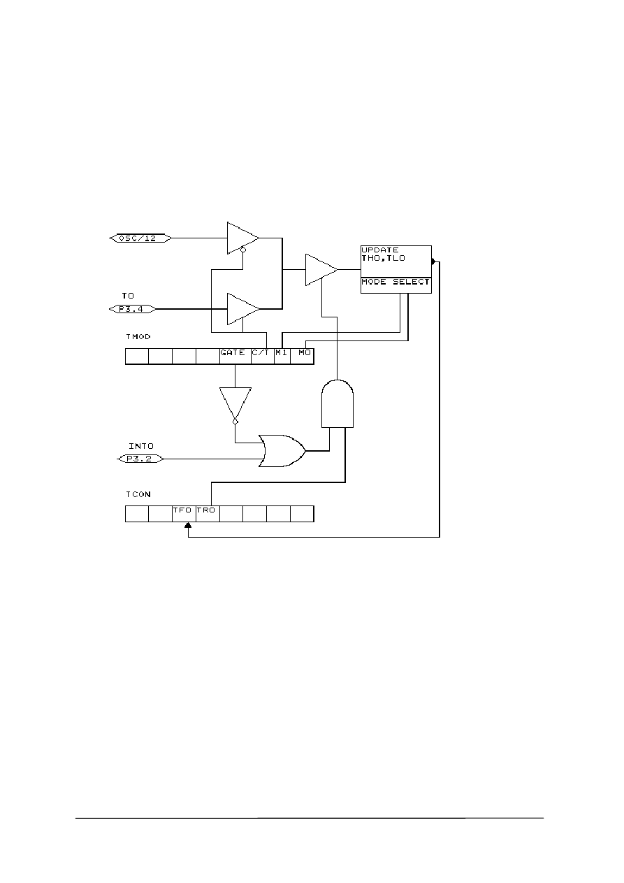
Timers and Counters
The AT89C2051 has two 16-bit timers. Named TIMER0 and TIMER1.
Below the internal representation of timer0 is shown. TIMER0 and TIMER1 are
almost identical so you can read TIMER1 for TIMER0.
Each counter register has two SFR’s associated with it. For TIMER0 the SFR’s are
TL0 and TH0. TL0 is the lowest byte of TIMER0 and TH0 is the highest byte of
TIMER0. These two registers make the timers 16-bit wide.
The timer can operate as a timer or as a counter.
A timer uses the systemclock divided by 12 as the source of its input pulses. So it
increments periodical.
A counter uses external pulses to increment its count.
The external pulses are received at alternative pin P3.4 for TIMER0 and P3.5 for
TIMER1.
The timer/counter can be controlled by the run-bit TR0.
You can stop a timer/counter with the statement STOP TIMER0/COUNTER0.
You can start a timer/counter with the statement START TIMER0/TIMER1.
The timer/counter can also be controlled with the alternative pin P3.2.
This pin is labeled for its alternative INT0-input but it can be used to control the timer.

BASCOM-8051 Version 2.00
Page -28-
When GATE is reset the timer/counter is enabled. When GATE is set the
timer/counter is enabled if INT0 is active(low). (provided that the timer is started)
The timer/counter can operate in four modes:
•
mode 0 : 13-bit counter.
An interrupt is generated when the counter overflows. So it takes 8192 pulses to
generate the next interrupt.
•
mode 1 : 16-bit counter.
Mode 1 is similar to mode 0. It implements a 16-bit counter. It takes 65536 input
pulses to generate the next interrupt.
•
mode 2 : 8-bit auto reload.
TL0 serves as an 8-bit timer/counter. When the timer/counter overflows the
number stored in TH0 is copied into TL0 and the count continues.
An interrupt is generated each time the counter overflows and a reload is
performed.
•
mode 3 : TIMER1 is inactive and holds its count. (TIMER1). For TIMER0 in timer
mode two 8-bit timers are available and in counter mode one 8-bit timer is
available. See a datasheet for more details.
The timer/counter can be configured with the CONFIG statement.
CONFIG TIMER0= COUNTER/TIMER, GATE=INTERNAL/EXTERNAL, MODE=0/3
The first argument is the timer/counter you want to configure.
GATE specifies if external timer control with the INT0 pin is enabled.
MODE specifies the timer/counter mode (0-3).
So CONFIG TIMER0 = COUNTER, GATE = INTERNAL, MODE=2 will configure
TIMER0 as a COUNTER with not external gatecontrol , in mode 2 (auto reload)
When the timer/counter is configured the timer/counter is stopped so you must start
it afterwards with the START TIMER0 statement.
The ON TIMERx statement can be used to respond to a timer/counter interrupt when
the timer overflows.
When the timer/counter is used in mode 2 (auto reload) the reload value can be
specified with the LOAD TIMERx, value statement.
Because it is an 8-bit register a maximum time of 255 uS can be achieved.
So for a period of 10 uS you must supply a value of (256-10) is 246. To make things
easier you can assign the value directly : LOAD TIMERx , 250 will internally be
transformed into 256-250=6. This saves you the trouble of calculating the correct
value.
The COUNTER0 and COUNTER1 variables hold the values of timer/counter 0 and 1.
You can also set the timer/counter contents with the COUNTER0 = value statement.
Port 3 is a unique port because it has alternative functions.
That is you can use it as a port like P3.1 = 1 or SET P3.1 or you can make use of the
double function of this port.
BASCOM-8051 Version 2.00
Page -29-
Port
Alternative function
P3.0
RxD receive data for RS-232
P3.1
TxD transmit data for RS-232
P3.2
INT0 interrupt 0 input/timer 0 gate control
P3.3
INT1 interrupt 1 input/timer 1 gate control
P3.4
T0 timer 0 input or counter input
P3.5
T1 timer 1 input or counter input
P3.5 -
P3.7 -
When you make use of the PRINT, INPUT and other RS-232 related statements
P3.0 and P3.1 are used for the RS-232 interface.
When you make use of the INT0/INT1 interrupts you must connect an interrupt
source to the corresponding pins. A switch for example.
The INTx interrupt can occur on the falling edge of a signal or when the signal is low.
Use the following statements to specify the trigger:
SET TCON.0
falling edge generates interrupt for INT0.
RESET TCON.0
low signal generates interrupt for INT0.
SET TCON.2
falling edge generates interrupt for INT1.
RESET TCON.2
low signal generates interrupt for INT1.
When TCON.x is RESET the interrupts keep on occurring while the input is low.
When TCON.x is SET the interrupt only occurs on the falling edge.
To test if a hardware interrupt is generated you can test the TCON.1 and TCON.3
flags. These flags are set by hardware when an external interrupt edge is detected.
They are reset by the RETURN statement of the interrupt service routine or
subroutine. TCON.1 must be tested for INT0 and TCON.3 must be tested for INT1.
Internal Registers
You can manipulate the register values directly from BASIC. They are also reserved
words. The internal registers are :
BIT addressable registers
TCON Timer/counter
control
P1
Port 0 latch
SCON
Serial port control
IE
Interrupt enable
P3
Port 3 latch
IP
Interrupt priority control
PSW
Program status word
ACC Accumulator
B
B register

BASCOM-8051 Version 2.00
Page -30-
BYTE addressable register
SP
Stack pointer
DPL
Data pointer low word
DPH
Data pointer high word
PCON
Power control
TMOD
Timer/counter mode control
TL0
Timer/counter 0 low byte
TL1
Timer/counter 1 low byte
TH0
Timer/counter 0 high byte
TH1
Timer/counter 1 high byte
SBUF
Serial data port
P1
Port 1 latch
P3
Port 3 latch
The registers and their addresses are defined in the REG51.DAT file which is placed
in the BASCOM application directory.
You can add your own files for uP’s that have more registers. These files must have
the .DAT extension.
The REG51.DAT file must be selected when you compile for the AT89X051, 8051 or
other 8051 compatible uP.
Take care when you are directly manipulating registers!
The ACC and B registers are frequently used by BASCOM.
Also the SP register is better to leave untouched. Altering SP will certainly crash your
application!
Bit addressable registers can be used with the SET/RESET statements and as bit-
variables.
Byte addressable registers can be used as byte variables.
P1 = 40 will place a value of 40 into port 1.
Please note that internal registers are reserved words. This means that they can’t be
dimensioned as BASCOM variables!
So you can’t use the statement DIM B as Byte because B is an internal register.
You can however manipulate the register with the B = value statement.
Power Up
At power up both ports are high. When you want to read a value from a port it must
be high!
So when you have set a port to zero and you want to use it as an input you must first
set it to 255.
Individual bits can also be set to use a port both as input/output.
For example : P1 = &B00001111 , will set a value of 15 to port 1.
P1.0 to P1.3 can be used as inputs because they are set high.

BASCOM-8051 Version 2.00
Page -31-
In line assembly
You can also use inline assembly language with BASCOM.
Assembler comment must be preceded by the ;-sign.
For example :
Dim a as byte
mov {a}, #10 ; variables must be enclosed with { }
Print a
Or you can include an assembler file :
$INCLUDE myasm.asm
Note that the file must have the extension .ASM
Initialization
BASCOM initializes the processor depending on the used statements.
When you want to handle this by yourself you can specify this by the metastatement
$NOINIT.
The only initialization that is always done is the setting of the stackpointer and the
initialization of the LCD-display (if statements are used).
BASCOM-8051 Version 2.00
Page -32-
BASCOM-8051 Version 2.00
Page -33-

BASCOM-8051 Version 2.00
Page -34-
D
Developing order, 23
E
Edit Copy, 10
Edit Cut, 10
Edit Find Next, 11
Edit Goto, 11
Edit Goto Bookmark, 11
Edit Indent Block, 11
Edit Paste, 10
Edit Redo, 10
Edit Replace, 11
Edit Search, 10
Edit Toggle Bookmark, 11
Edit Undo, 10
Edit Unindent Block, 12
Editor Keys, 22
Error codes, 24
F
File Close, 8
File Exit, 9
File New, 8
File Open, 8
File Print, 9
File Print Preview, 9
File Save, 8
File Save As..., 9
H
Hardware, 25
Hardware related commands, 26
Help About, 21
Help Credits, 21
Help Index, 21
Help on help, 21
I
I2C, 26
In line assembly, 31
Initialization, 31
Installing BASCOM-8051, 3
Internal Registers, 29
O
Options Communication, 18
Options Compiler, 16
Options Environment, 18
Options Hardware Simulator, 19
Options Monitor, 19
Options Printer, 19
Options Programmer, 19
P
Power Up, 30
Program Compile, 12
Program Send to chip, 15
Program Show result, 12
Program Simulate, 13
Program Syntax Check, 12
T
Tools LCD designer, 16
Tools Terminal Emulator, 15
W
Window Arrange icons, 20
Window Cascade, 20
Window Minimize all, 20
Window Tile, 20
Wyszukiwarka
Podobne podstrony:
Bascom 8051 i AVR Instrukcja PL(1)
Bascom 8051 i AVR Instrukcja PL
8051 id 47295 Nieznany
Asm i C dla 8051 Nieznany (2)
8051 lista rozkazow, ELEKTRONIKA I PROGRAMOWANIE, Mikroprocesory, programowanie Bascom, AVR,
8051 id 47295 Nieznany
Gor±czka o nieznanej etiologii
02 VIC 10 Days Cumulative A D O Nieznany (2)
Abolicja podatkowa id 50334 Nieznany (2)
45 sekundowa prezentacja w 4 ro Nieznany (2)
4 LIDER MENEDZER id 37733 Nieznany (2)
Mechanika Plynow Lab, Sitka Pro Nieznany
katechezy MB id 233498 Nieznany
2012 styczen OPEXid 27724 Nieznany
metro sciaga id 296943 Nieznany
Mazowieckie Studia Humanistyczn Nieznany (11)
cw 16 odpowiedzi do pytan id 1 Nieznany
więcej podobnych podstron