
Reference number
ISO 128-50:2001(E)
©
ISO 2001
INTERNATIONAL
STANDARD
ISO
128-50
First edition
2001-04-15
Technical drawings — General principles of
presentation —
Part 50:
Basic conventions for representing areas
on cuts and sections
Dessins techniques — Principes généraux de représentation
Partie 50: Conventions de base pour la représentation des surfaces sur
des coupes et des sections
SIS-2002-577
2001

ISO 128-50:2001(E)
PDF disclaimer
This PDF file may contain embedded typefaces. In accordance with Adobe's licensing policy, this file may be printed or viewed but shall not
be edited unless the typefaces which are embedded are licensed to and installed on the computer performing the editing. In downloading this
file, parties accept therein the responsibility of not infringing Adobe's licensing policy. The ISO Central Secretariat accepts no liability in this
area.
Adobe is a trademark of Adobe Systems Incorporated.
Details of the software products used to create this PDF file can be found in the General Info relative to the file; the PDF-creation parameters
were optimized for printing. Every care has been taken to ensure that the file is suitable for use by ISO member bodies. In the unlikely event
that a problem relating to it is found, please inform the Central Secretariat at the address given below.
© ISO 2001
All rights reserved. Unless otherwise specified, no part of this publication may be reproduced or utilized in any form or by any means, electronic
or mechanical, including photocopying and microfilm, without permission in writing from either ISO at the address below or ISO's member body
in the country of the requester.
ISO copyright office
Case postale 56
·
CH-1211 Geneva 20
Tel. + 41 22 749 01 11
Fax + 41 22 749 09 47
E-mail copyright@iso.ch
Web www.iso.ch
Printed in Switzerland
ii
© ISO 2001 – All rights reserved

ISO 128-50:2001(E)
© ISO 2001 – All rights reserved
iii
Foreword
ISO (the International Organization for Standardization) is a worldwide federation of national standards bodies (ISO
member bodies). The work of preparing International Standards is normally carried out through ISO technical
committees. Each member body interested in a subject for which a technical committee has been established has
the right to be represented on that committee. International organizations, governmental and non-governmental, in
liaison with ISO, also take part in the work. ISO collaborates closely with the International Electrotechnical
Commission (IEC) on all matters of electrotechnical standardization.
International Standards are drafted in accordance with the rules given in the ISO/IEC Directives, Part 3.
Draft International Standards adopted by the technical committees are circulated to the member bodies for voting.
Publication as an International Standard requires approval by at least 75 % of the member bodies casting a vote.
Attention is drawn to the possibility that some of the elements of this part of ISO 128 may be the subject of patent
rights. ISO shall not be held responsible for identifying any or all such patent rights.
International Standard ISO 128-50 was prepared by Technical Committee ISO/TC 10, Technical product
documentation, Subcommittee SC 1, Basic conventions.
This first edition of ISO 128-50 is based on ISO 128:1982, subclauses 4.1 to 4.3 of which it cancels and replaces.
ISO 128 consists of the following parts, under the general title Technical drawings — General principles of
presentation:
¾
Part 20: Basic convention for lines
¾
Part 21: Preparation of lines by CAD systems
¾
Part 22: Basic conventions and applications for leader lines and reference lines
¾
Part 23: Lines on construction drawings
¾
Part 24: Lines on mechanical engineering drawings
¾
Part 25: Lines on shipbuilding drawings
¾
Part 30: Basic conventions for views
¾
Part 34: Views on mechanical engineering drawings
¾
Part 40: Basic conventions for cuts and sections
¾
Part 44: Sections on mechanical engineering drawings
¾
Part 50: Basic conventions for representing areas on cuts and sections
The following part is under preparation:
¾
Part 1: Introduction and index


INTERNATIONAL STANDARD
ISO 128-50:2001(E)
© ISO 2001 – All rights reserved
1
Technical drawings — General principles of presentation —
Part 50:
Basic conventions for representing areas on cuts and sections
1
Scope
This part of ISO 128 specifies general principles for representing areas on cuts and sections on technical drawings
(mechanical, electrical, architectural, civil-engineering etc.) following the orthographic projection methods specified
in ISO 5456-2.
Attention has also been given to the requirements of reproduction, including microcopying in accordance with
ISO 6428.
NOTE
The basic rules for cuts and sections are given in ISO 128-40
[1]
.
2
Normative references
The following normative documents contain provisions which, through reference in this text, constitute provisions of
this part of ISO 128. For dated references, subsequent amendments to, or revisions of, any of these publications
do not apply. However, parties to agreements based on this part of ISO 128 are encouraged to investigate the
possibility of applying the most recent editions of the normative documents indicated below. For undated
references, the latest edition of the normative document referred to applies. Members of ISO and IEC maintain
registers of currently valid International Standards.
ISO 128-20, Technical drawings — General principles of presentation — Part 20: Basic conventions for lines.
ISO 128-24:1999, Technical drawings — General principles of presentation — Part 24: Lines on mechanical
engineering drawings.
ISO 5456-2, Technical drawings — Projection methods — Part 2: Orthographic representations.
ISO 6428, Technical drawings — Requirements for microcopying.
ISO 10209-1, Technical product documentation — Vocabulary — Part 1: Terms relating to technical drawings:
general and types of drawings.
ISO 10209-2, Technical product documentation — Vocabulary — Part 2: Terms relating to projection methods.
3
Terms and definitions
For the purposes of this part of ISO 128, the terms and definitions given in ISO 10209-1 and ISO 10209-2 apply.
ISO 128-50:2001(E)
2
© ISO 2001 – All rights reserved
4
General
This part of ISO 128 specifies six methods for the representation of areas on cuts and sections. These consist of
indication
¾
by hatching (see clause 5),
¾
by shading or toning (see clause 6),
¾
by extra-wide continuous outlines (see clause 7),
¾
of thin sections (see clause 8),
¾
of thin adjacent sections (see clause 9), and
¾
of special materials (see clause 10).
Allowance shall be made for the means of reproduction used, in accordance with ISO 6428.
5
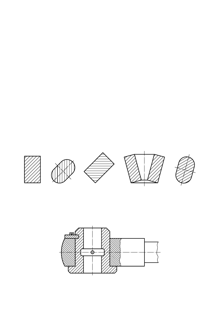
Hatching
Hatching shall be done with the narrow continuous lines of type 01.1.5 specified in ISO 128-24:1999 and at a
convenient angle (preferably 45
°)
to the principal outlines or lines of symmetry of cuts or sections (see Figure 1).
Figure 1 — Hatching of areas of cuts or sections — Examples
Separate areas of a cut or section of the same component shall be hatched in an identical manner. The hatching of
adjacent components shall be carried out using the specified lines running in different directions or differently
spaced (see Figure 2).
Figure 2 — Hatching of adjacent areas
ISO 128-50:2001(E)
© ISO 2001 – All rights reserved
3
Spacing between the hatching lines should be chosen in proportion to the size of the hatched areas, provided this
is in accordance with the requirements for minimum spacing given in ISO 128-20.
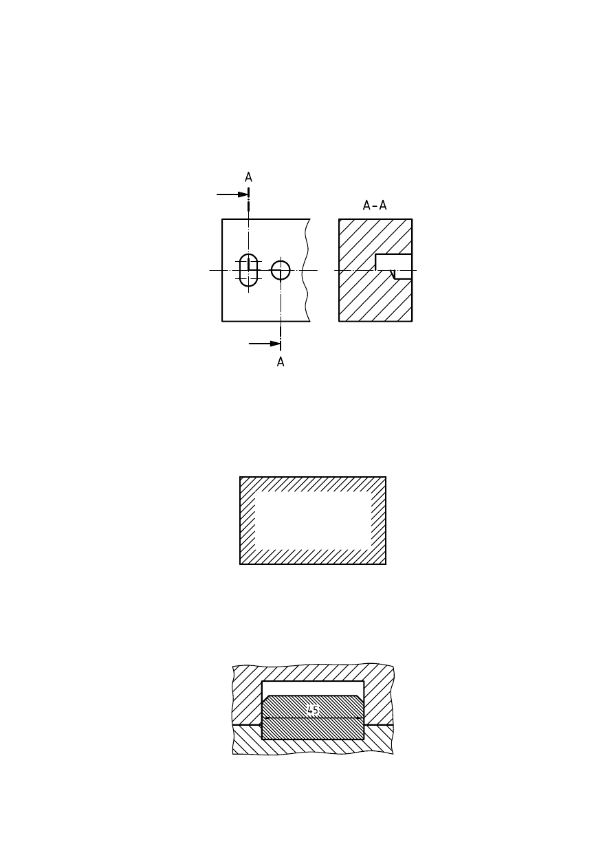
Where cuts or sections of the same part in parallel are shown side by side, the hatching shall be identical (see
Figure 3), but may be offset along the dividing line between the cuts or sections for greater clarity.
Figure 3 — Hatching of an area parallel cuts or sections
In the case of a large area, the hatching may be limited to a zone that follows the contour of the area (see
Figure 4).
Figure 4 — Hatched contour of large area
Hatching shall be interrupted for inscriptions inside an area (see Figure 5).
Figure 5 — Hatching interrupted by inscription
ISO 128-50:2001(E)
4
© ISO 2001 – All rights reserved
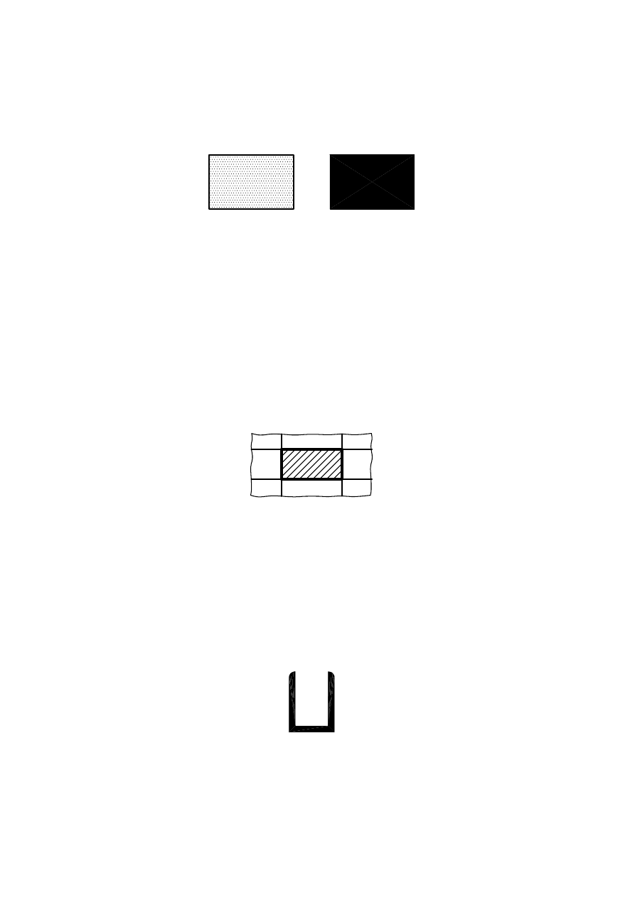
6
Shading or toning
Shading may consist of a pattern of dots or an overall toning of area (see Figure 6).
Figure 6 — Shading using dots and toning
Spacing between dots should be chosen in proportion to the size of a shaded area. In the case of a large area, the
shading may be limited to a zone that follows the area’s contour (Figure 4).
Shading or toning shall be interrupted for inscriptions inside an area (Figure 5).
7
Extra-wide continuous outlines
Areas of cuts and sections may be emphasized by the extra-wide continuous line specified in ISO 128-20 (see
Figure 7).
Figure 7 — Extra-wide continuous outline for emphasis
8
Thin sections
Thin sections may be shown entirely black (see Figure 8).
This method shall represent true geometry.
Figure 8 — Thin sections

ISO 128-50:2001(E)
© ISO 2001 – All rights reserved
5
9
Thin adjacent sections
Solid sections may be shown entirely black. A space of not less than 0,7 mm shall be left between adjacent sections of
this type. See Figure 9.
This method does not represent true geometry.
Figure 9 — Thin adjacent sections
10 Specific materials
Different types of special representation can be used to indicate specific materials. If a special representation is
used, its signification shall be clearly defined on the drawing (e.g. by a legend, or by reference to appropriate
standards).

ISO 128-50:2001(E)
6
© ISO 2001 – All rights reserved
Bibliography
[1]
ISO 128-40, Technical drawings — General principles of presentation — Part 40: Basic conventions for cuts
and sections.


ISO 128-50:2001(E)
ICS 01.100.01
Price based on 6 pages
© ISO 2001 – All rights reserved
Wyszukiwarka
Podobne podstrony:
50 Year of Architecture lr
50 Flavors of Creampuff
F1 Other areas of tax
50 Dressing of Nature (printable)
Coaching Specialities 100 Areas of Specialty
The 12 Areas of a Perfect Life
50 Years Of Playboy
Lose Weight Forever 50 Habits Of Naturally Thin People
Design Fatigue Test and NDE of a Sectional Wind Turbine Rotor Blade
50 Inspekcja sekcji Section playing examined Nov 3 2013
50 Common Birds An Illistrated Guide to 50 of the Most Common North American Birds
50 707 719 Thermal Fatique and Softening Behaviour of Hot Work Steels
Fat Dragon Games Fold Up E Z Dungeons Free Caverns of Chaos Wall Section
An introduction to the Analytical Writing Section of the GRE
Implementation of budget (EAGGF Guidance Section) (2004)
ISO128 44 sections mechanical
Analysis of spatial shear wall structures of variable cross section
więcej podobnych podstron