
REVISIONS
REV
DESCRIPTION
DATE
APPROVED
SHEET
OF
1
7
DRAWN
CHECKED
ENGRG
ISSUED
DIMENSIONS ARE IN INCHES/MM
TOLERANCES ON:
2 PL DECIMALS
3 PL DECIMALS
ANGLES=
FRACTIONS=
UNLESS OTHERWISE NOTED
SIGNATURES
DATES
SIZE
A
SCALE
GEGS NO
DWG NO
44A751556
TITLE
INSTALLATION INSTRUCTIONS
THIRD ANGLE PROJECTION
VERSION LEVEL
DIST
621
INSTRUCTIONS FOR UPGRADING
IC693CPU364 WITH VERSION 10.60 FIRMWARE
PER UPGRADE KIT 44A747767-G07
This CPU model has operating firmware stored in FLASH memory. The firmware upgrade is provided on CD, or downloaded from the
WEB, or shipped on diskettes. To perform the upgrade using a personal computer (PC) running Microsoft Windows
â, refer to the
section “Updating Firmware Under Windows” below for instructions to use the WinLoader program. The program that you run on the
PC is referred to as the ”Firmware Update Utility” in the instructions that follow.
NOTE: The instructions provided outline a specific sequence of procedure that MUST be followed. If the procedure for some
reason is not followed, please contact the GE FANUC hotline for help in setting up the PLC. FLASH MEMORY WILL NOT
BE PRESERVED OVER UPDATE. ANY PROGRAM STORED IN FLASH WILL BE LOST.
TO PERFORM THE FIRMWARE UPGRADE, YOU WILL NEED TWO CABLES:
1.
a Station Manager Serial Cable (IC693CBL316), AND
2.
a standard programmer cable (see the table at the end of this document for options)
TO INSTALL NEW FIRMWARE RECEIVED ELECTRONICALLY, PERFORM THE FOLLOWING
STEPS:
1. Extract the zip file named a R1060 36x PS.ZIP from the main zip file named cpu364-r1060.zip.
2. Create a Directory named “CPU” and extract all files from the zip file named R1060 36x PS.ZIP to it, or extract all files
from the zip file named R1060 36x PS.ZIP to a single high density diskette. . Note: If the Update is received on a CD, the
Directory may already exist and the files will already be extracted.
3. If you extracted to a diskette, label that diskette “ SNP Port on Power Supply”
4. Create a different Directory named “ENET” and extract all files from the zip file named R120 EEM P1.ZIP to it, or extract
all files from the zip file named R120 EEM P1.ZIP to a single high density diskette. . Note: If the Update is received on a
CD, the Directory may already exist and the files will already be extracted.
5. If you extracted to a diskette, label that diskette “Port 1 on CPU-Ethernet”.

REVISIONS
REV
DESCRIPTION
DATE
APPROVED
SHEET
OF
2
7
DRAWN
CHECKED
ENGRG
ISSUED
DIMENSIONS ARE IN INCHES/MM
TOLERANCES ON:
2 PL DECIMALS
3 PL DECIMALS
ANGLES=
FRACTIONS=
UNLESS OTHERWISE NOTED
SIGNATURES
DATES
SIZE
A
SCALE
GEGS NO
DWG NO
44A751556
TITLE
INSTALLATION INSTRUCTIONS
THIRD ANGLE PROJECTION
VERSION LEVEL
DIST
621
TO INSTALL THE NEW FIRMWARE, PERFORM THE FOLLOWING STEPS:
PREPARE THE PLC.
1. Save or backup any programs or data resident in the module before performing the update function. NOTE:
PLC PROGRAM AND CONFIGURATION WILL BE LOST DURING THE UPGRADE.
2. Place the PLC in STOP/NOIO Mode.
3. Clear any faults in the PLC.
4. Set the memory protect switch (labeled as “Keyswitch” in accompanying figure) to the OFF position.
5. Clear the configuration in your PLC. This will set the power-supply port baud rate to 19200 and the Ethernet RS-232
port baud rate to 19200. (If they are already set to default values, then this step may not be necessary.)

REVISIONS
REV
DESCRIPTION
DATE
APPROVED
SHEET
OF
3
7
DRAWN
CHECKED
ENGRG
ISSUED
DIMENSIONS ARE IN INCHES/MM
TOLERANCES ON:
2 PL DECIMALS
3 PL DECIMALS
ANGLES=
FRACTIONS=
UNLESS OTHERWISE NOTED
SIGNATURES
DATES
SIZE
A
SCALE
GEGS NO
DWG NO
44A751556
TITLE
INSTALLATION INSTRUCTIONS
THIRD ANGLE PROJECTION
VERSION LEVEL
DIST
621
***Updating Firmware Under Windows (For Windows 95 Windows NT, Windows
98, Windows 2000, Windows XP, NOT WINDOWS 3.1): ***
You will need an IBM compatible PC running Windows, with an RS-232 port. If you extracted the ZIP files to a diskette, or you
received the upgrade on diskettes your PC will need to be equipped with a 3.5 inch high-density diskette drive. The firmware update
process requires 500 KB of hard drive space. If you are using Windows 3.xx or Windows NT 3.51, contact GE Fanuc technical support.
6-WIN When updating a CPU364, you should install the Ethernet firmware first. Using a standard Station Manager cable
(IC693CBL316), connect the serial port of your PC to port 1 on the 364 CPU module (refer to Figure 1 to locate
port). (Note: the Ethernet firmware file is named eem_tcp.emf.)
7-WIN Goto the ENET directory you created and extracted files to. If using diskettes insert the diskette labeled “Port 1 on
CPU - Ethernet” into the diskette drive of your PC and goto the diskette drive in Explorer.
8-WIN Invoke the WinLoader either by double clicking on “winloader.exe” displayed by Windows Explorer or use the
“Run…” selection of the Start menu and specify the location of the WinLoader Utility, e.g. “A:\winloader”.
9-WIN You must do this to prepare the CPU364 to receive the Ethernet firmware load, follow the steps below:
Press the ETHERNET RESTART button and hold it down for five seconds (refer to Figure 1 to locate button). When
the button is first pressed, all three green LED indicators will go out. After five seconds, the bottom LED will go on,
indicating that the CPU364 will enter the Ethernet load state when the button is released. Release the button
immediately after the buttom LED goes on. All three LEDs will flash briefly, then the top LED will flash, and then all
3 LEDs will blink simultaneously. At this point, your CPU364 is ready to accept the Ethernet firmware load. (Note:
if you hold the restart button down too long, the CPU364 will enter Ethernet maintenance mode rather than Ethernet
firmware load mode. To return to operational mode, press and hold the restart button briefly (less than 5 seconds).
Then re-execute the instructions in this step.)
If all three LEDs are not blinking after this step, but your CPU364 seems to operate normally when first powered on,
there may be a hardware failure of Port 1. Use LogicMaster 90 or Control 90 to check the PLC fault table for a
"Module hardware fault" message from rack 0 slot 1. You can also check the text displayed by the Ethernet firmware's
local station manager
NODE
command for a "Power up diagnostics result" message about the port. See TCP/IP
Ethernet Communications for the Series 90 PLC Station Manager Manual, GFK-1186, for details. The Firmware
Update Utility will not be able to update the Ethernet firmware if there is a hardware failure of the CPU364 Port 1.
The CPU module should be replaced.
10-WIN The WinLoader Utility used COM1 port of your PC by default. If you connected your cable to COM1, skip the rest of
this step. If you connected your cable to a different COM port, use WinLoader’s “COM Port” drop-down box to select
the proper COM port.
11-WIN In most cases, you should not need to adjust the serial port settings that the WinLoader Utility uses. If your Ethernet
Interface’s S/W Load port configuration is set for:
·
19,200 baud
·
ODD parity

REVISIONS
REV
DESCRIPTION
DATE
APPROVED
SHEET
OF
4
7
DRAWN
CHECKED
ENGRG
ISSUED
DIMENSIONS ARE IN INCHES/MM
TOLERANCES ON:
2 PL DECIMALS
3 PL DECIMALS
ANGLES=
FRACTIONS=
UNLESS OTHERWISE NOTED
SIGNATURES
DATES
SIZE
A
SCALE
GEGS NO
DWG NO
44A751556
TITLE
INSTALLATION INSTRUCTIONS
THIRD ANGLE PROJECTION
VERSION LEVEL
DIST
621
·
8 data bits
·
1 stop bit
·
0 modem turnaround time,
then no adjustment is necessary. If other settings are used, you must modify the serial port configuration used by the
Firmware Update Utility to use the same serial configuration as Port 1 each time you run the Firmware Update Utility.
To do this, click the “Settings” button and select the matching serial port settings. Then click “OK” to activate the
new settings.
12-WIN Click the “Update” button to begin loading the new Ethernet firmware. A progress bar appears at the bottom right
portion of the window.
13-WIN Upon completion of the update, a window will appear indicating the completion status of the update. If the load
completes successfully, the Firmware Update Utility will ask if you want to perform another update
1
. Click “no”. If
you are using diskettes remove the Ethernet update diskette from the drive. Go to step 15-WIN below to update the
CPU firmware.
14-WIN If the firmware load fails, a window appears indicating the specific error condition that occurred. Take appropriate
steps to correct the error and retry the update. Refer to Restarting An Interrupted Firmware Upgrade below.
15-WIN Next, connect one of the serial ports of your PC to the serial port on the power supply (refer to Figure 1) next to the
PLC to be updated using one of the cable/converter combinations listed at the end of this document.
16-WIN Goto the CPU directory you created and extracted files to. If using diskettes insert the disk labeled “SNP Port on
Power Supply” into the diskette drive of your PC and goto the diskette drive in Explorer.
17-WIN Invoke the WinLoader by double clicking on “winloader.exe” displayed by Explorer or use the “Run selection of the
Start menu and specify the location of the WinLoader Utility, e.g. “A\winloader”. (Note: The name of the CPU
firmware file is 360_1.emf)
18-WIN Click the “Update” button to begin loading the new CPU firmware. A progress bar appears at the bottom right portion
of the window. Note: WinLoader will attempted to determine the baud rate of the PLC port. Occassionally WinLoader
will fail to detect the baud rate and fail to connect. If this happenes retry the “Update”.
19-WIN Upon completion of the update, a window will appear indicating the status of the update. If the update was successful,
power cycle the PLC. All new firmware has been installed. Click “no” to indicate that no additional updates will be
performed. If the update was not successful, see the Common Causes of Failure section to determine how to correct
the mistake.
1
If you are performing a bulk update of a large number of CPU364s, you may update all the modules’ Ethernet firmware first and then
all the modules’ CPU firmware. Note that all of the CPU364s will be tied up with the update process while the bulk update is in
progress.

REVISIONS
REV
DESCRIPTION
DATE
APPROVED
SHEET
OF
5
7
DRAWN
CHECKED
ENGRG
ISSUED
DIMENSIONS ARE IN INCHES/MM
TOLERANCES ON:
2 PL DECIMALS
3 PL DECIMALS
ANGLES=
FRACTIONS=
UNLESS OTHERWISE NOTED
SIGNATURES
DATES
SIZE
A
SCALE
GEGS NO
DWG NO
44A751556
TITLE
INSTALLATION INSTRUCTIONS
THIRD ANGLE PROJECTION
VERSION LEVEL
DIST
621
Common Causes of Failure
1.
CPU fault table not empty. Using WinLoader: a dialog box will appear saying “CPU State Mismatch.”
WinLoader will ask if it’s OK for WinLoader to clear fault tables and place PLC in STOP/NOIO mode. Select yes and
proceed.
2.
Connected to wrong serial port Using WinLoader: a dialog box will appear saying “FIRMWARE UPDATE
FAILED” and listing several possible reasons why the firmware update failed. Examine cable connections and move cable
to Power Supply port (refer to Figure 1). Power cycle PLC and go to step 16-WIN.
3.
Memory protect keyswitch at wrong position. Using WinLoader: an error message will appear that indicates
that a FLASH erase operation failed. Place key switch in Off/Stop position (refer to Figure 1 to locate keyswitch). Power
cycle PLC and start at step 16-WIN.
4.
Updating in incorrect order. The correct order is Ethernet and then CPU firmware. Be sure to follow the
instructions sequentially. If an update has already been attempted in the incorrect order, please contact the GE Fanuc
Hotline for help and instructions. .
5.
Cannot connect to the target device. **Applies to WinLoader only** After verifying all of the items listed in
the Firmware Update Status dialog box, press OK. Then press the “Settings” button to bring up the WinLoader Settings
dialog. Change the “Connect Baud” combo box from “Auto” to “19200”. Press OK and start over at step 18-WIN.

REVISIONS
REV
DESCRIPTION
DATE
APPROVED
SHEET
OF
6
7
DRAWN
CHECKED
ENGRG
ISSUED
DIMENSIONS ARE IN INCHES/MM
TOLERANCES ON:
2 PL DECIMALS
3 PL DECIMALS
ANGLES=
FRACTIONS=
UNLESS OTHERWISE NOTED
SIGNATURES
DATES
SIZE
A
SCALE
GEGS NO
DWG NO
44A751556
TITLE
INSTALLATION INSTRUCTIONS
THIRD ANGLE PROJECTION
VERSION LEVEL
DIST
621
Restarting an Interrupted Firmware Upgrade
A. Carefully check the cables, the RS-232/RS-485 converter, and all connections.
B. If you are restarting the Ethernet firmware upgrade, briefly press and release the Ethernet Restart button. Depending on how
far the previous upgrade progressed before it failed, your CPU364 may be ready to perform the Ethernet firmware upgrade or it
may restart into operational mode. If all three LEDs are blinking simultaneously, skip to step D now.
C. If you are restarting the CPU firmware upgrade, power cycle the module and verify that the memory protect switch is set to
the OFF position. If a partial or erroneous download was performed, the module will power up with the OK and RUN LEDs
on the power supply flashing in unison.
D. You must exit the Firmware Update Utility (on the PC) and start it again, then repeat the upgrade process. If your previous
attempt progressed beyond the FLASH memory erase step, began loading data blocks, and then displayed an error message or
stalled, try a lower baud rate.
REVISIONS
REV
DESCRIPTION
DATE
APPROVED
SHEET
OF
7
7
DRAWN
CHECKED
ENGRG
ISSUED
DIMENSIONS ARE IN INCHES/MM
TOLERANCES ON:
2 PL DECIMALS
3 PL DECIMALS
ANGLES=
FRACTIONS=
UNLESS OTHERWISE NOTED
SIGNATURES
DATES
SIZE
A
SCALE
GEGS NO
DWG NO
44A751556
TITLE
INSTALLATION INSTRUCTIONS
THIRD ANGLE PROJECTION
VERSION LEVEL
DIST
621
GE Fanuc Cables and RS-232/RS-485 Converters
IC690ACC901
GE Fanuc/Horner Mini Converter with Cable, or
IC690ACC900
GE Fanuc Converter (requires cable IC690CBL303 and either IC690CBL702 or IC690CBL705 below)
IC690CBL303
15-pin RS-442 Serial Cable
IC690CBL702
9-pin RS-232 Serial Cable
IC690CBL705
25-pin RS-232 Serial Cable
IC693CBL316
GE Fanuc Station Manager Serial Cable
Approximate Download Times for CPU364 Upgrades
19200 baud less than 5 minutes
9600 baud less than 8 minutes
300 baud less than 3 hours
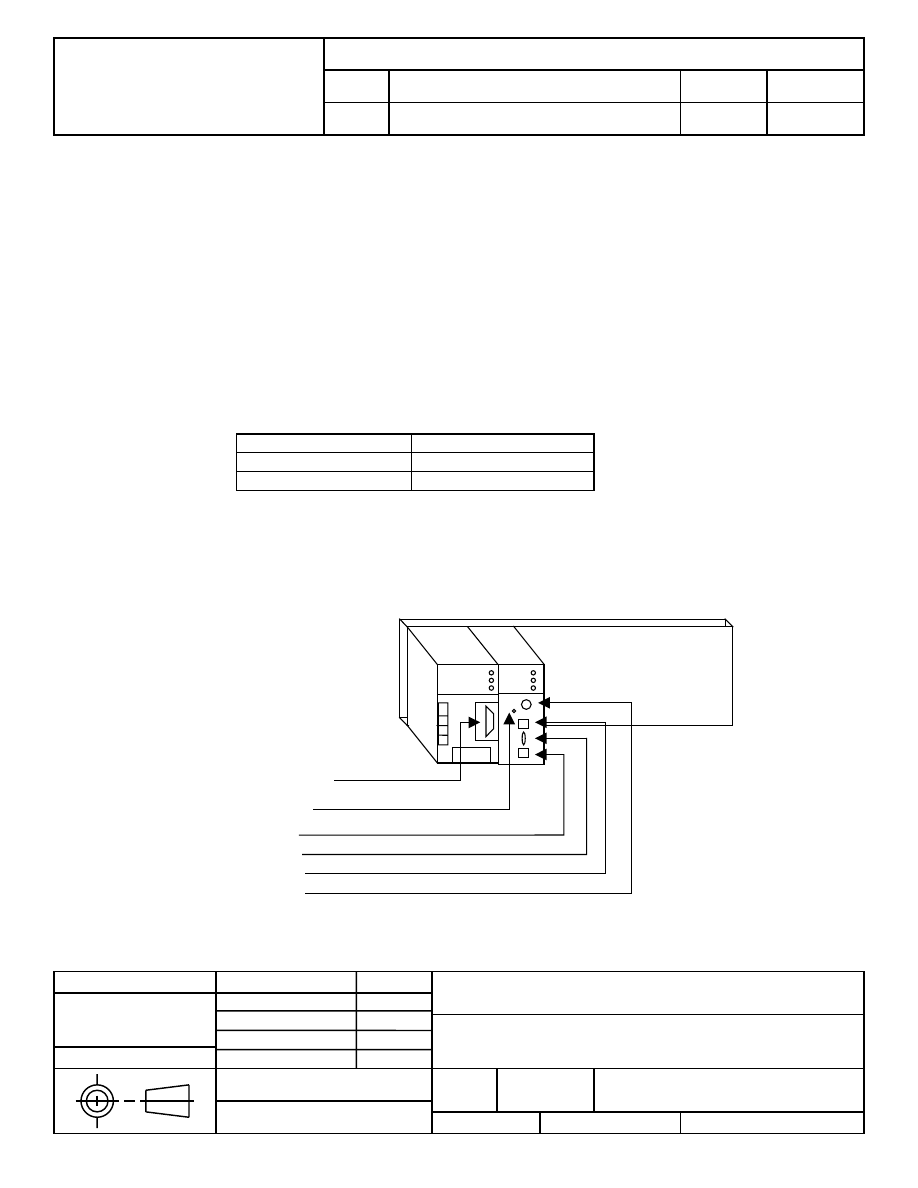
Simple Port Diagram
Power Supply Port
Keyswitch
Port1 RS-232
Port2 AAUI
Figure 1: Port
Diagram for the
model CPU364
Port3 10BaseT
Ethernet Restart
Wyszukiwarka
Podobne podstrony:
cpu364 update instructions
cpu363 update instructions
G500 GPS firmware Update Instruction Guide
cpu363 update instructions
cpu350 update instructions
ds708 update instruction obdtoolshop co uk
cpu360 update instructions
cpu360 update instructions
firmware update instruction
V30 Software Update Instruction
Instrukcja Aktualizacji modelu KDL 32EX720 TV Firmware update
key pro m8 auto key programmer update token instruction
więcej podobnych podstron