Page 1
MAGNUM
METAL LOCATOR
ANDY FLIND
Cheap metal detectors are usually disappointing in use whilst good ones tend to be very expensive. Although there is a lot of
work involved in building the machine in this article, it can be completed for around £40-50, less than a quarter of the cost of
most ready-made ones of similar performance. It is not strictly a design for the beginner to attempt, but a step by step construction
and test procedure has been devised to make it as simple as possible. The only absolutely essential item of test equipment required
is a reasonable quality test meter.
Until now, most metal detector designs for the home constructor have been BFOs. True, there have been one or two notable
exceptions, but even these were relatively unsophisticated examples of their type, so readers might be interested in a brief
description of the basic methods of detection and the reasons for the choice of system used in this design.
TYPES OF DETECTOR
Broadly speaking there are five main ways of detecting metal; BFO (beat frequency oscillator), induction balance, pulse
induction, off resonance, and the magnetometer. The latter works by detecting small anomalies in the Earth’s magnetic field
strength. It’s fascinating but quite useless for treasure hunting since it can detect only ferrous objects. The BFO and off resonance
types both operate by detecting the small changes in the search coil inductance which occur when a metal object is present. Both
suffer from a basically poor sensitivity. Some sophisticated attempts have recently been made to produce a really good off
resonance machine, so far without obvious success.
Pulse induction detectors are another matter however; good ones are very sensitive indeed and some of the most expensive
detectors currently available are these. They operate by exposing the ground to powerful pulses of magnetism and listening
between the pulses for signals due to eddy currents set up in any metal objects present in the field. Despite their sensitivity they
have a couple of important drawbacks. Their battery consumption is heavy due to the power required by the pulsed transmitter,
and they are extremely sensitive to even tiny ferrous objects. Their use is thus primarily restricted to beach searching, where
objects are likely to be buried at considerable depths, and where large holes can be easily and rapidly dug. On inland sites, their
users can become discouraged by the frequent digging of large holes in hard ground to recover rusty nails, etc.
This leaves the induction balance types which have become
more or less the standard general purpose detector for both
serious treasure hunters and detecting hobbyists alike. It has
two coils in its search head, one of which is fed with a signal
which sets up an alternating field around it. The other coil is
placed so that normally the field around it balances and it has
no electrical output. A metal object approaching the coils will
distort the field, resulting in an imbalance so the pickup coil
will produce an output. This can be amplified and used to
inform the operator of a “find” in a variety of ways. Frequently
in simple detectors an audio modulated transmitted signal is
used, the output from the pickup coil then being amplified and
demodulated like an AM radio signal. There are many possible
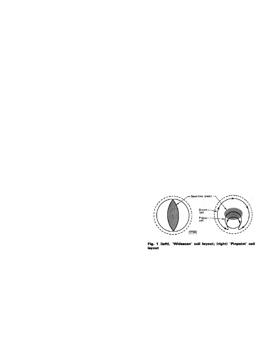
coil arrangements, but most detectors available today use one of the two shown in Fig. 1. Fig. l(a) shows a “widescan” coil, so
called because its most sensitive area (shaded) extends right across the coils Fig. 1(b) shows a “pinpoint” type, also known as a
“4B”. In the author’s experience the pinpoint is by far the better coil in use, as widescans have poor pinpointing ability and tend to
give false signals for ferrous objects off centre, coins on edge and the like. It’s noticeable that many of the best imported
American machines use pinpoint coils.
DISCRIMINATION
All of this is fine, but there are a couple of extra refinements necessary in a really good metal detector. One of these is the
ability to discriminate between unwanted junk such as silver paper, scraps of iron etc., and desired objects. The other is some
means of eliminating false signals due to “ground effect”. Ground capacitance effects can easily be prevented by Faraday
shielding around the coils, but most inland soils contain a proportion of iron oxide which gives a signal similar to a piece of
ferrite. Beaches wet with seawater on the other hand are slightly conductive, and this too causes false signals to be produced in the
pickup coil. Obviously some means of “tuning out” these effects will improve the detector considerably.
PE

Page 2
Fortunately the signals from the search coil consist of more than just amplitude variations; they also contain information in the
form of phase shifts which differ markedly according to the type of object causing the signal. With a relatively simple phase
sensitive detector therefore, a machine can be designed which will totally reject ground effects and can also, with practice on the
part of the user, eliminate the majority of the rubbish detected without the necessity of having to dig it up.
NOMENCLATURE
Some of the terms used by manufacturers to describe their machines in recent years have been somewhat confusing so, before
we proceed, a note on these may not be amiss. ‘VLF’ stands for “very low frequency”. The ability to discriminate from phase
information against thin section objects like foil depends on frequency. At higher frequencies, ‘Skin effect’ eddy current
conduction makes such discrimination ineffective. Therefore manufacturers began using lower and lower frequencies, at least one
machine actually worked at less than 2kHz. This created problems of its own, as at such low frequencies sensitivity to cupro-
nickel coins is not so good and “Q” problems arise in the coil design. Most detectors nowadays operate somewhere between 10
and 20kHz. where discrimination is still excellent but sensitivity and coil design problems do not arise.
“GEB” means “ground exclusion balance” and refers to the phase sensitive means of excluding ground effect. “TR” means
“transmit-receive” and is often used to describe the discriminate mode, suggesting that the machines operate with different
frequencies or coil configurations in the different modes--they don’t: the only thing that is changed between modes is the phas e
reference point. It is not possible to avoid ground effect and discriminate at the same time, so one normally searches in GEB
mode, and on finding an object, checks it with the discriminate mode before digging. Beer can pull rings can be rejected by the
way, but machines capable of doing this will also reject any cupro-nickel coin smaller than a 10p when set to do so. It is probably
better to tolerate the rings - many charities now collect these anyway.
BLOCK
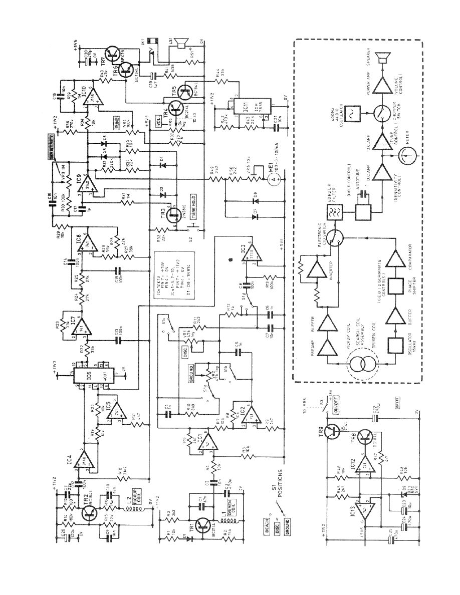
Fig. 2 (dotted) shows a schematic of the Magnum detector. The drive oscillator sets up a field around the search coil, and the
pickup coil is positioned so that it only gives an electrical output when a metal object distorts this field. The operating frequency
of these stages is approximately 15kHz Signals from the pickup coil are amplified, buffered and then inverted so that non-inverted
and inverted versions of it are simultaneously available. These are fed to the two inputs of an electronic changeover switch,
operated by a reference signal derived from the drive oscillator. This reference signal has first been passed through a phase
shifting network which can be adjusted as required by the user. The output from the switch is passed through a 3rd order low-pa ss
active filter with a cut-off point set at 40Hz. which removes practically all of the 15kHz signal, leaving only the average d.c. level.
Any given signal producing object causes changes in both magnitude and phase of the received signal, so by adjusting the phase
shift network correctly a point can be found where these changes either cancel out or cause a net fall in the d.c. level, enabling
unwanted signals from ground, foil, iron etc., to be eliminated. Incidentally, most similar designs to date have used either pulse
sampling phase detectors, or have selected only half-cycles of the input signal. The use of the inverter and changeover switch
requires very few extra components and greatly improves the signal-to-noise ratio, ultimately resulting in more sensitivity.
After the filter, the d.c. signal is amplified. It is only changes in the signal that are of interest, so a means of “tuning out” the
initial standing d.c. level is required. In simple machines this is a manual control, but the need for readjustment after each
operation of the phase controls - say switching from “ground” to “discriminate” - makes some form of automatic tuning desirable.
On most commercial machines a “tune” button resets the output to zero every time it is pressed, hut these are notoriously prone to
drift. Attempts to use continuously resetting systems have been made, but this tends to lower the overall sensitivity as most
manufacturers use rather crude filtering, resulting in considerable delay in the response to a detected object. In effect the autotune
tries to reset the output to zero at the same time as the detected object is trying to cause it to rise! The highly efficient filtering
used in this design ensures an instant response to a signal, so a continuously resetting tuning system can be used. This does away
with all the drift problems, and allows the machine to be used continuously at maximum sensitivity if required. A “freeze” button
is provided to stop the tuning action whilst pinpointing the exact position of finds or discriminating.
After the autotune and amplifier stage the signal is fed to a centre-zero meter; in “discriminate” this indicates positive for
“good” finds and negative for “bad” ones. Then it goes to a further amplifier with a control which sets the point at which the
audio output is to start. The output from this is of course still d.c., so it is chopped up by an audio oscillator, providing a signal
which only needs a power output stage to drive the loudspeaker.
CIRCUIT
Fig. 2 shows the complete circuit of the machine. TR1 and associated components form the drive oscillator, which provides a
very pure 15kHz sinewave output. IC1 buffers part of this signal and the circuitry around IC2 introduces the phase shift as
required. In “ground” the available shift is about -10 to +40 degrees, whilst in “discriminate” and “beach” it is about 0 to -170
degrees. IC3 is a comparator; the 3130 was chosen for its high slew rate and good output drive signal for the CMOS switch IC6.
TR2 is the received signal preamp and is connected as a common base amplifier. This and oscillator TR1 are both based on
Page 3
Page 4
designs which have been used in several manufactured machines because they
are simple and work well. The receive coil L2 is untuned; this, coupled with
the low impedance input load of TR2 ensures the predictable phase response
required for reliable discrimination. The output of TR2 is at high impedance
so IC4 acts as a buffer, whilst IC5 is a unity gain inverter. IC6 is connected as
a CMOS electronic changeover analogue signal switch. IC7 and IC8 together
are the 3rd order low-phase active filter.
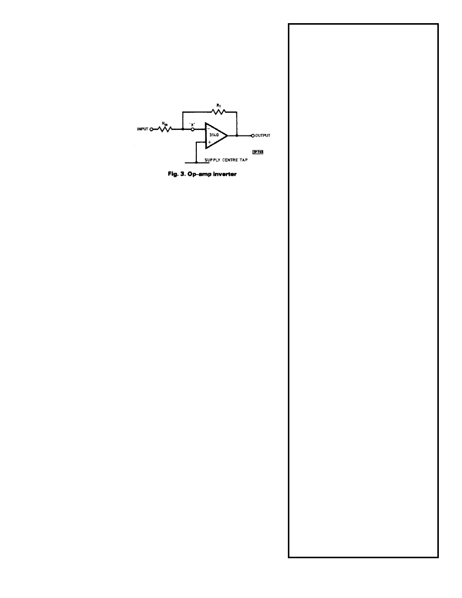
IC9 is a d.c. amplifier
and also the auto-tune
stage. The action of this is
probably easier to
understand if one first
considers an ordinary
opamp inverting amplifier,
as shown in Fig. 3. If the
+input is at 0 volts, the -
input must also be at 0
volts, so if a voltage is
applied to the input resistor R
in
the output will change until it restores the 0
volts at the -input via R
f
. Now consider the effect of placing a capacitor at
point “x”. If the output is connected directly to the -input, it will go to 0 volts.
If at the same time a voltage is applied to R
in
, the capacitor will acquire a
charge. If the output is now disconnected from the -input it will remain at 0
volts because the capacitor will retain the charge necessary to the input
voltage. A change in the input voltage will be reflected in a change in the
output voltage, the gain given by R
f
/R
in
, In this way an amplifier can be
constructed using only one opamp which will offset large d.c. voltages and yet
provide high d.c. amplification of very small input voltage changes.
In the main circuit TR3 provides a means of connecting the output to the -
input. The output is divided by R33 and R34 and fed through R3l, so that the
reset rate is relatively slow but continuous, as TR3 is normally conducting. If
the tuning error is very large however, as it would be after switching on or
operating the discriminating controls, D5 or D6 will conduct and greatly
accelerate the tuning rate. D3 and D4 prevent the gate junction of TR3 from
becoming forward biased at any time.
VR4 sets the threshold of IC10 and is normally adjusted to that it’s output is
at negative rail voltage. On receipt of a signal it rises towards positive. IC11 is
a low-power 555 timer connected as an astable oscillator, giving very short
(about 100 microsecond) negative pulses at about 400Hz. Thus TR5 is
normally on and turns off only during these pulses so after R40 any output
from IC10 is chopped into short positive going pulses. This is the ideal
waveform to create lots of noise with an economic power consumption. The
volume control in a design such as this is normally only required to limit the
maximum noise level, so in this design VR5 and TR4 act as an adjustable
clamp. In this way the sensitivity is not reduced if the volume has to be kept
turned down. TR6 and TR7 are a complementary Darlington pair, their current
gain enabling the signal to drive the loudspeaker or headphones.
SUPPLIES
Two separate power supplies are used in this machine. The bulk of the
circuitry is supplied with 18 volts from two PP3 batteries in series, regulated
by the circuit around IC12 and IC13. With so many opamps its far easier to
arrange the design around a centre-tapped supply, so the reference generated
by the Zener is buffered by IC13. It is then doubled by IC12, TR8 and TR9, to
give a regulated positive rail of twice the Zener voltage, nominally +11.2
COMPONENTS
RESISTORS
R1,4,5,7,8,19,20,29,35,38,46,48
10k
R2,16
15k
R3
3k3
R6,9,21,47
4k7
R10
3k9
R11,49,50
2k2
R12
1k
R13,17,30
100k
R14
180k
R15,28,32,34,43
22k
R18
2M2
R22,23,44
33k
R24,25
27k
R26,27
39k
R31,39
1M
R33,37
220k
R36
270k
R40
47k
R41
6R8
R42
470k
R45
2k7
POTENTIOMETERS
VR1,2
47k log carbon
VR3
1M lin. carbon
VR4
100k lin. carbon
VR5
10k log with switch
VR6
10k preset, sub min horiz.
CAPACITORS
C1,C10
47n polyester
C2
470n polyester
C3,7,9,16,18,21
10n polyester
C4,5,6
1n polystyrene
C8,12,13,14,15
100n polyester
C11
22p polystyrene
C17
1
µ
F polycarbonate
C19
4.7
µ
F 63v electrolytic
C20,24,25,26
470
µ
F 16v electrolytic
C22
470
µ
F 25v electrolytic
C23
10
µ
F 25v electrolytic
DIODES
D1 to 8
1N914
D9
BZY88C 5V6, 5.6v Zener
TRANSISTORS
TR1,4,9
BC214L
TR2,5,6,8
BC184L
TR3
2N3819
TR7
BFX29
INTEGRATED CIRCUITS
IC1,2,5,7,8,12,13
741
IC3
CA3130
IC4,9,10
CA3140
IC6
4007UBE
IC11
ICM7555
MISCELLANEOUS
S1, 4-pole 3-way rotary switch, S2, miniature press to
make, Meter, 100-0-100 microamp center zero, LS1- 2-1/2
in. 8-ohm loudspeaker, 12 off 8-pin d.i.l. i.c. holders, 1 off
14-pin d.i.l. i.c. holder, 5-pin DIN plug and socket,
headphone socket, 3 PP3 battery clips, 32 and 36 SWG
enammelled copper wire, 5A bare tinned copper fuse wire,
2 metres of 4-core individually screened cable, case, Vero
type 75-1411-D, 6 control knobs, approx 25mm skirt, plus
plastic plumbing components, “Melaware” plate,
glassfibre repair kit etc. to make coil, stem, and handle -
see text.
Kits available from Maplin ELectronics Supplies Ltd.
Page 5
volts. This arrangement has been used in preference to an integrated regulator since it will operate until the battery voltage has
fallen to only 0.1 volt above the regulator output. Most integrated regulators require a differential of at least 2 volts, which in
practice means that the batteries have to be replaced rather more frequently. The total power consumption of all this circuitry is
about 20mA, less than many radios at normal volume.
Power for the loudspeaker output stage comes from a separate 9 volt battery, as this is the simplest way of avoiding decoupling
difficulties in this very sensitive circuit. An extra PP3 is far smaller than the decoupling capacitors which would otherwise be
required. Only the one power supply switch is required as the output draws no current unless an input signal is present.
CONSTRUCTION
Construction is on two printed circuit boards and should be adhered to as this is a very sensitive circuit indeed; the result of any
changes may well prove to be severe instability. The two boards are stacked vertically in the final assembly resulting in a control
box which is smaller and neater than many very expensive manufactured products.
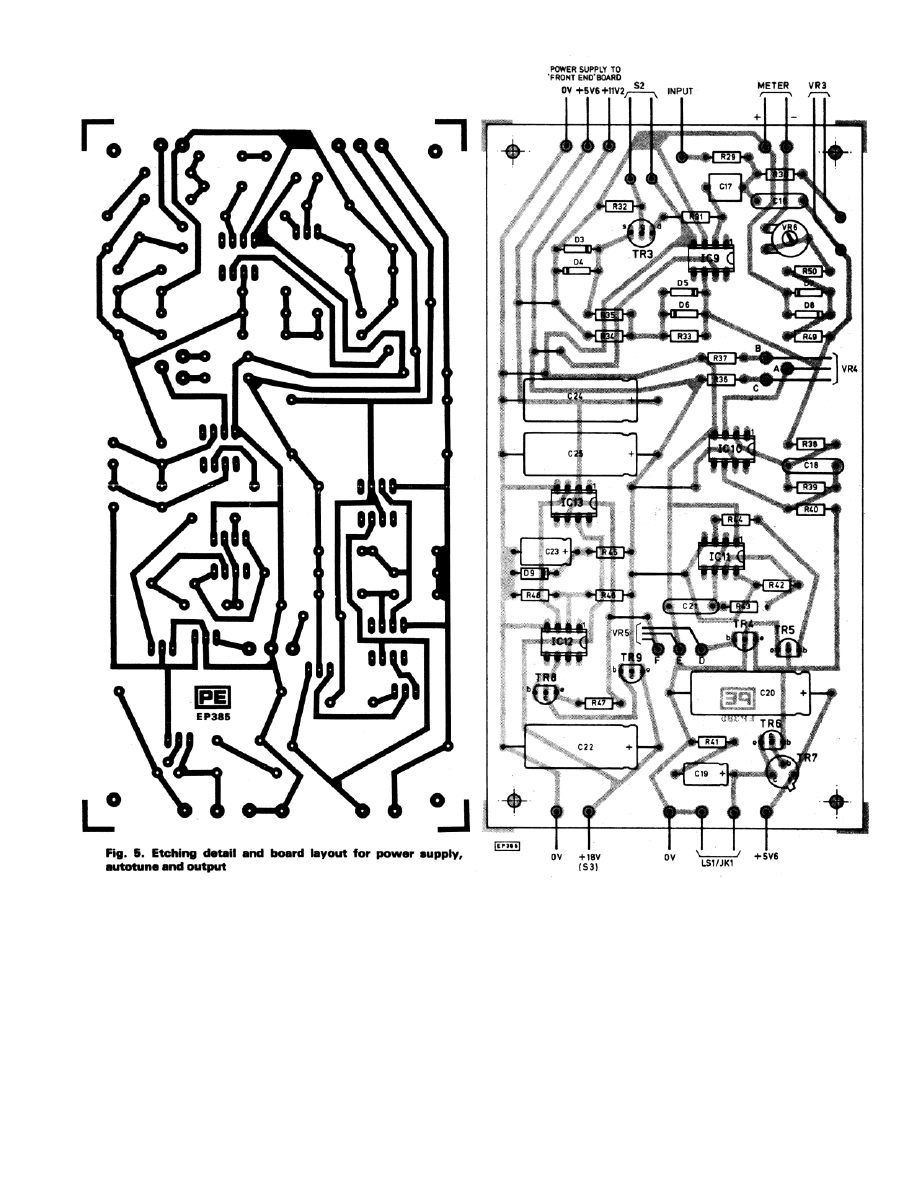
The board containing the power supply, autotune and output should be built first as the power supply will be required for testi ng
the “front end” board (Fig. 5).
ASSEMBLY DETAILS
Start construction by fitting the six links. The fit R45 to R48, C22 to C25, ZD1, TR8, TR9, IC12 and IC13. Apply the 18 volt
battery via a 100mA meter and a 220 ohm series resistor, which will limit the current if any faults are present. It’s as well to use
this resistor throughout the testing of both boards. After a brief surge as the eletrolytics charge the current should settle to about
5mA. Check that about 11 volts appears across C25. and about 5.5 volts across C24. This completes the power supply section.
Continue by fitting R40 and R41, C19 and C20, TR6 and TR7. Hook up the speaker, apply the 9 volt power supply via the
100mA meter and a 100 ohm resistor, again in case a fault is present. After a brief surge the current drawn should drop to zero. A
finger on R40 and the battery positive at the same time should cause a crackle and an indicated current flow. Fit R42 to R44,
C21,TR5 and IC11. IC11 is the low power 555 timer; despite the manufacturers’ notes to the contrary these are a little sensitive to
handling so treat it with care and use a holder. I.c. holders are advisable throughout in fact; there is ample room for them. Apply
both power supplies. A finger on 9 volts positive and on R40 should now produce the 400Hz output tone, albeit possibly at rather
Page 6
low volume. After this the 100R resistor can be left out of the 9 volt supply during testing, although the 220R in the 18 volt
supply should be retained. Fit TR4 and hook up VR5. Apply power supplies, place fingers on R40 and 9 volts positive, and check
that the volume can be controlled with VR5. This is one of those many jobs in electronics for which one requires three hands!
Fit R33, R34, R36 to R39, C18, and IC10. IC10 may be in either an 8-pin d.i.l. package, or the round metal T079 version. You
can now hook up VR4 and apply power. It should be possible to turn the output tone on and off with VR4 - gradually, since the
input of IC10 at this stage is effectively taken to the supply centre-tap via R33 and R34 which reduces its gain somewhat. If there
is no output tone check that the volume isn’t turned right down.
FINAL TEST
Fit all the remaining components to this board. Hook up S2, VR3 and the meter. Short the input point to the battery centre-tap.
Apply power; the meter should return to zero within a couple of seconds due to the autotune action. Adjust VR4 to just below the
Page 7
tone threshold point. Touch the 18 volt battery positive with one hand, and, taking a 10M resistor in the other, touch the top end of
R29 via the resistor. This should produce a brief burst of tone and a positive jump on the meter, which will then return to zero.
Repeat this procedure whilst pressing S2 - the sound and meter deflection produced should then be continuous. Press the button,
and touch either of the 18 volt battery leads end the bottom of C17. This should cause the meter to drive fully up or down, and its
full scale deflection can then be adjusted with VR6.
Next month: details will be given of the remainder of the construction and using the detector.
Part 2 (Practical Electronics, Sept. 1980)
LAST month the general principles of the GEB detector were explained, and construction of a machine began with a p.c.b.
comprising power supply, auto-tuning and output stages. This month the remainder of the construction will be covered.
SEARCH COILS
It’s best to begin by winding the search coils, which will
be required for testing the front-end circuit board at various
stages. The Magnum uses a pinpoint coil, for reasons
explained last month: these are slightly harder to make than
widescans but the results obtainable are well worth the effort.
The coil assembly is based on a 10in dia. ‘Melaware’ plate,
made from a very rigid plastic, obtainable from most stores
selling picnic tableware.
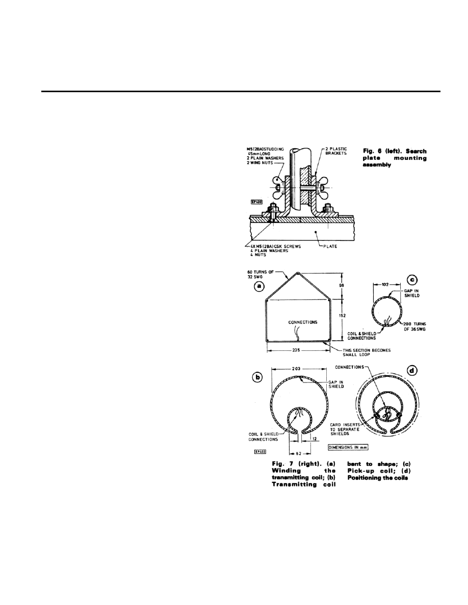
The inside of the plate is thoroughly roughened with glass
paper to enable glassfibre resin to stick to it, and two ‘L’
shaped-plastic brackets are bolted to the top as in Fig. 6.
These were cut from a thick, strong square-shaped clip
intended for mounting square section plastic drain pipes to
exterior walls, obtained from a local builders’ merchants.
They are bolted to the plate with 2BA countersunk screws
with the heads inside, so nothing protrudes to foul the coils.
A hole is drilled just behind one of the brackets to allow a
4core screened cable to pass through.
The two coils are wound on pins pushed into a suitable
board. The larger transmitting coil is made with just five Fins
positioned as shown in Fig. 7a, on which 60 turns of 32
s.w.g. enamelled copper wire is wound. It can be tied
temporarily with a few twists of wire and removed from the
pins--this is fiddly but not too difficult--bent to the shape of
Fig. 7b, and bound tightly with a spiral of thin bare wire such
as 5 amp fusewire, leaving a loop near the lead wires for use
as a connection. Remove the temporary ties as the binding
proceeds. A strip of aluminium cooking foil is then wrapped
over the bare wire to form a Faraday shield, and this is held
in place with another tight binding of the bare wire. Note that
both wire bindings and the foil must have a gap--this is most
important, as if the Faraday shield were allowed to r form a
complete ‘turn’ around the circumference of the coil it would
render it useless.
PICKUP COIL
The pickup coil is made in the same manner, consisting of 200 turns of 36 s.w.g. enamelled copper wire wound around 16 pins
placed in a 4in diameter circle. Faraday shielding is fitted as on the transmitting coil, again with the all-important gap.
The transmitting coil can now be fixed in place on the former using a small quantity of fibreglass resin. A Holts’ ‘Fibreglass
Repair Kit’, obtainable from motoring accessory shops, was used in making the prototype. The coil is best fixed in stages, using
clothes pegs and weights to keep it in place as necessary. Apply the resin with a soft brush and have a jar of cellulose thinners
handy to dunk the brush into the moment it starts to ‘gel’. Push the 4-core screened lead through the hole in the plate, connect the
Page 8
coil leads to two of the cores, and the Faraday shield to the screens. It can be difficult to keep the lead in place whilst the resin
sets; one way of doing this is to drill two tiny holes on each side of it and secure it flat against the plate with a couple of twists of
thin wire. The pickup coil is not fitted at this stage.
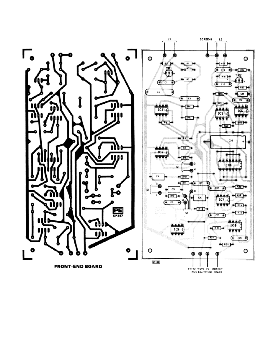
FRONT-END PCB
Start building the ‘front-end’ circuit board by fitting all the links. Then fit R1 to 3, C1,2, and 26, Dl, and TR1. Hook up the
transmitting coil and apply power from the supply board. Continue using a resistor in series with the 18 volt battery in case a ny
faults arise during tests, as described last month. The transmit oscillator should now be running, at between 15 and 16kHz. Thi s
can be checked by placing a radio tuned to a weak longwave station very close to the coil-faint whistles due to harmonics of the
transmitted signal beating with station carries should be present. Faint is the word, however, as the Magnum’s oscillator produces
Page 9
a very clean signal. This and other parts of the circuit can be more easily checked with a ‘scope of course, but if you have one
you’ll probably have realised this anyway.
Next fit R4 to 13, C3 to 8 and IC1. Apply power and check that IC1’s d.c. output voltage (at pin 6) is equal to 5.6v. Fit IC2,
apply power and check IC2’s d.c. output is 5.6v. Fit IC3, hook up VR1 across points I and J, VR2 across points G and H, and fit
some lengths of wire so that point M may be shorted to points K or L, and short one of these. It doesn’t matter which at this stage.
Apply power and check that IC3B d.c. output (pin 6) is 5.6V. The output of IC2 should actually be switching from rail to rail at
the oscillator’s frequency but the average value of output should be 56V. A fault will usually result in its being fully driven to one
of the supply rails, so this is a useful test. Check that settings of VR1 (M shorted to L) and VR2 (M to K) makes little or no
difference to IC3’s output voltage.
It might be of interest to explain that in the original design, the pots were connected directly as they are in this test, and a 2-way
switch was fitted to M, K and i. This provides ‘Ground Reject’ (VR2) and ‘Discriminate’ (VR1). However, on the first beach
outing it was found that the ‘Beach Effect’ could only be rejected with the ‘Discriminate’ control. a predictable effect since
beaches are usually conductive. This prevented the discrimination from being used to reject foil, of which large amounts are to be
found on most beaches. To overcome this problem the switching was rearranged to provide a third ‘Beach’ position, in which
VR2 is effectively switched into the discriminate circuit instead of the ground one. Thus VR2 can then be used to reject false
signals from wet beaches in the same way as from ground, whilst VR1 can once again be used to check finds as intended.
Continue the construction by fitting R14 to 21, C9 to 12 and TR2. Connect the pickup coil temporarily, apply power and check
that the emitter voltage of TR2 is approximately 0·6 volts above the negative rail. Fit IC4, apply power and check IC4’s output
voltage (pin 6) is 5·6V. Fit IC5, apply power and check that the output of IC5 is also V/2.
Fit R22 to 28 and C13 to 15. Fit IC6, observing the usual
CMOS handling precautions for this chip. Place the pickup
coil in approximate position over the transmitting coil, apply
power and monitor the top end of R22 with a meter. The
voltage present should be somewhere between 2 and 8 volts
and should alter if VR1 or VR2 (whichever is selected by
shorting M to K or L) is moved. Adjust the pickup coil
position to obtain 5·6V at the top end of R22. Note that the
Faraday shields of the coils shouldn’t touch even though they
are both connected to the lead screens: if they touch on both
sides they can form a ‘shorted turn’ in the middle of the
assembly. Small pieces of card should be placed between
them to prevent this from happening.
Fit IC7, check it’s output is the same as that at the top of
R22, i.e. 56V. Fit IC8. Check 56V is still present at IC7 pin 6-
-if not adjust coil position. Then check that 5.6v is also
present at the output of IC8. This completes the construction
of the front-end p.c.b.
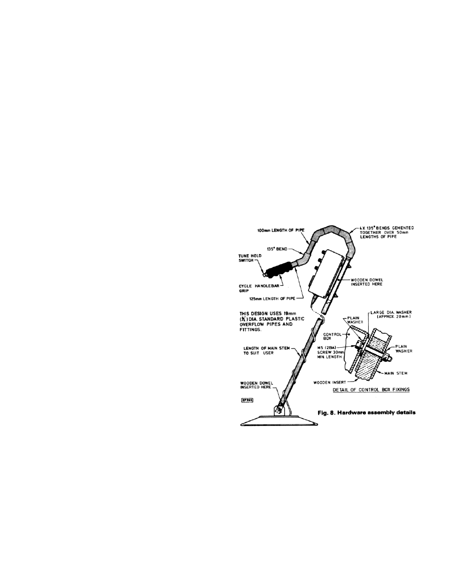
HARDWARE ASSEMBLY
The rest of the hardware can be constructed next. This is
made mainly from 3/4in diameter plastic plumbing pipe and
fittings, assembled as shown in Fig. 8. It’s simply glued and
pushed together, making a very presentable handle and stem
in a surprisingly short time. Wood dowelling is inserted at
strategic points of the stem to prevent it from flattening when
bolts are passed through it and tightened. The search coil is fixed by a length of studding passing through the two brackets and the
end of the stem, with a wingnut at each end, so that it’s tilt may be easily adjusted by the user. The control box base is secured to
the shaft with two bolts, and the tuning button is fitted into the end of a bicycle handlebar grip which is then pushed onto the
plastic pipe, threading the wires through the pipe to emerge through a small hole close to the control box.
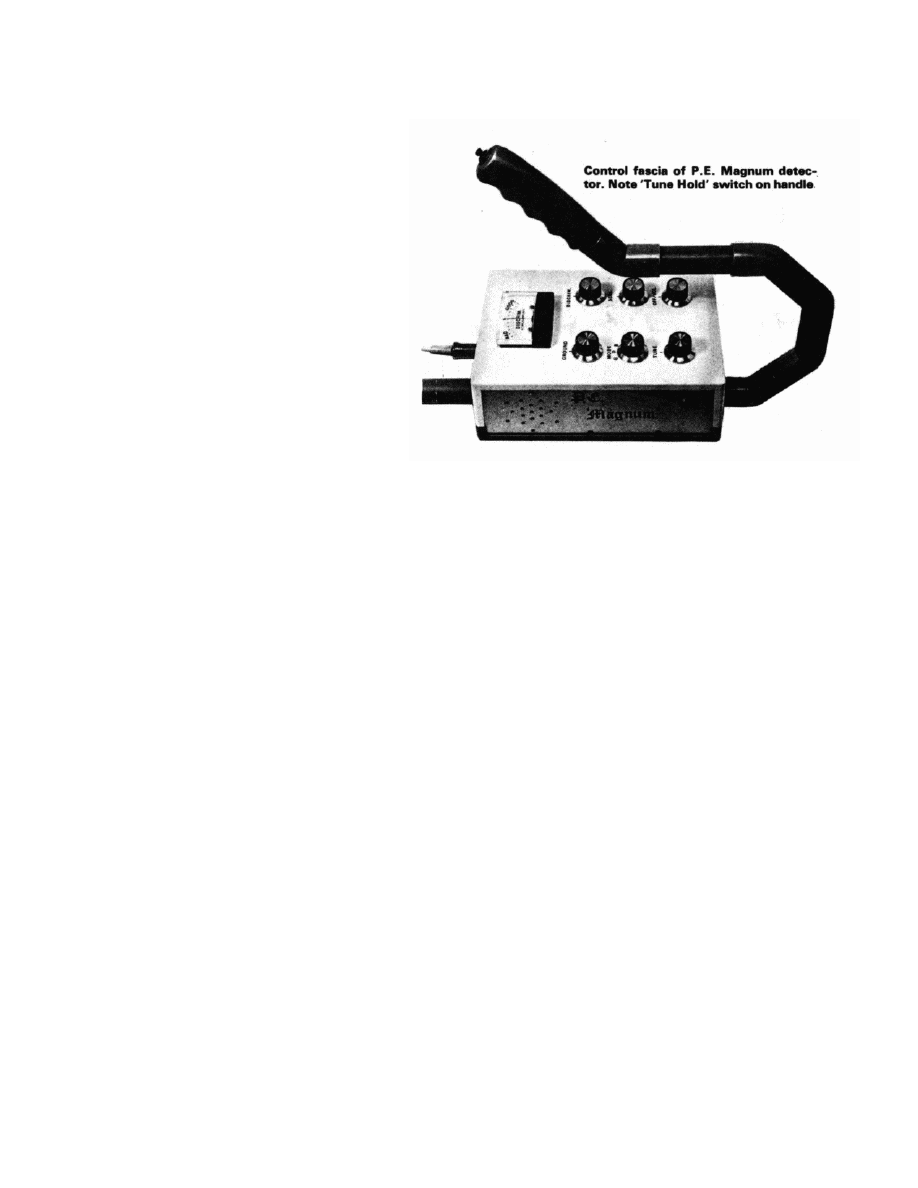
CONTROL BOX ASSEMBLY
The electronics now have to be assembled into the control box. The top should be cut to accept meter, pots and switch in the
layout shown in Fig. 9. Note that the top only fits the base one way round before starting this! A pattern of holes can be cut in one
of the aluminium side panels to act as a speaker fret, the speaker being glued into place. A clip to hold the three PP3 batteries is
fashioned from sheet aluminium and wood and bolted to the same panel, and to the ends of the bolts a piece of Veroboard is
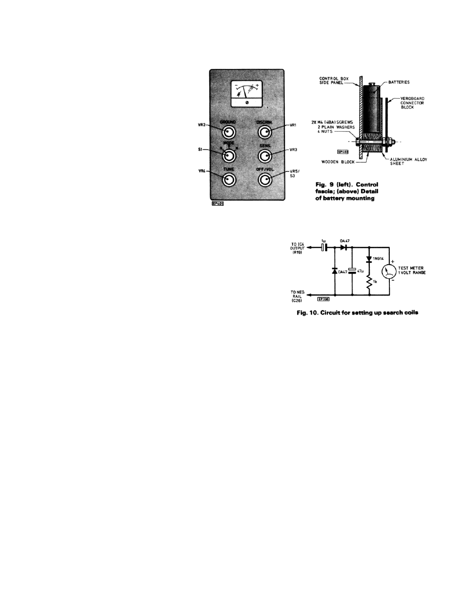
Page 10
attached to act as a connecting block for the leads from the batteries and tuning button. Four 4BA bolts passing up through the
base of the box act as stand-off pillars on which the two b.c. boards are mounted one above the other, the front-end board being
uppermost.
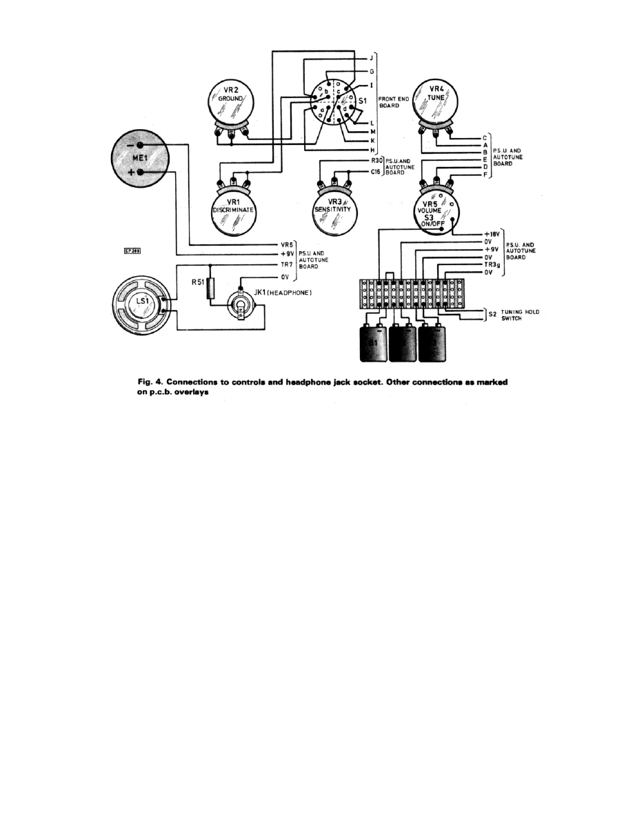
The best way to make all the connections to
the boards is with ribbon cable, soldering this
to them before fitting them into the case and
noting the point to which each coloured wire
goes. A headphone socket is optional: if
required it may be connected as shown in Fig.
5. ‘R’ will have to be selected for the phones to
be used, in the prototype a value of 100 ohms
was found to be suitable. A 5-pin DIN plug and
socket was used for the coil lead, whilst not
strictly necessary this does allow for
experimenting with different coils at a later
date.
The box specified is supplied with feet which
were discarded, the securing bolts being
shortened a little to compensate.
SETTING UP THE SEARCH COILS
When all the components have been wired up the final tricky part has been
reached; the setting up of the search coils. This must be done with metal
parts such as the securing bolt and wing nuts in place, though there is no
need to have the coil assembled to the stem. There should be no large metal
objects close to the coil during this stage. This might also be a good time to
mention that the machine can be affected by line timebase radiation from
625-line TV sets, so if you get a ‘mushy’ sound or a pulsed audio effect from
it, check this first. Coil adjustment is actually not as critical as it is for a
normal IB machine, but there is a best point and for a GEB machine it is the
position where absolute minimum residual amplitude output (and maximum
phase shift effect) is obtained from the pickup coil. (Conventional IBs
usually work best with a slight ‘offset’ from absolute null.) This cannot be monitored with the phase sensitive detector in the
machine itself, so the circuit of Fig. 10. should be lashed up and connected to IC4 output (top end of R19) and used with the 1 volt
range of a testmeter to facilitate setting up minimum amplitude.
Set VR1, VR2 and VR3 to mid-point. Switch to ‘Discriminate’ and switch on. The meter monitoring amplitude will probably
indicate full scale. Carefully adjust the pickup coil position until the reading falls - this may take some patience as it’s easy to
push the coil right past the null position without noticing it if you’re too hasty. Remember to keep those Faraday shields apart!
Once you have the coils somewhere near the null, try presenting metal objects to the coil whilst watching the centre-zero meter. A
non-ferrous object such as a copper coin should cause it to rise, whilst a ferrous object such as a nail should cause a fall. If the
opposite happens the phase of the pickup coil must be reversed, either by turning it over or by reversing its lead connections.
Once correct coil phase has been established setting up consists of adjusting the pickup coil position for absolute minimum
output from the amplitude monitoring test circuit, use resin to stick it down in stages, rechecking the adjustment at each stage.
Final fine trimming can be done with only a small section of the pickup coil still moveable.
After the positioning of the coils has been completed the coils can be given a coat of resin, followed by a layer of chopped
strand glassfibre mat and more resin, which produces a search head assembly that is neat, tough and totally waterproof. One word
of caution; don’t use more resin than you have to or the finished head may be heavier than necessary.
FINAL ASSEMBLY AND TESTS
All the test components can now be removed and the machine finally assembled and tested. If you’ve never used a GEB
machine before, you’re in for some pleasant surprises.
On switching on, the meter should self-zero within a couple of seconds and the tuning control should then be set just below the
threshold of the audio tone. The sensitivity of this machine is quite incredible; on most inland sites you’ll probably need to keep
the sensitivity control set to around mid-point. With the switch in ‘Ground’ position, a point can be found on the ‘Ground’ control
Page 11
where moving the head to and from the ground has no effect whatever - on one side of this point there will be positive ground
effect, on the other negative, so it’s not difficult to find. Adjusting this control for wet beaches is the same, except that the switch
should be set to ‘Beach’.
Once an object has been located, the machine
should be switched to ‘Discriminate’ and the nature
of the object determined. A certain amount of
ground effect will be apparent in this mode,
depending upon the actual terrain being searched.
Ferrous objects produce a negative response at all
settings of the discriminate control, but as this
control is advanced so the machine will begin to
reject small pieces of silver paper, then larger
pieces, thick foil, and finally pull rings. It should be
noted that in the pull-ring reject setting, however, it
will also reject silver coins up to about 10p size. All
discriminators suffer from this problem; but the
ability to reject scrap iron and foil without difficulty
is an absolute boon. Some practice with assorted
objects - coins, nails and scraps of foil etc., is
recommended before setting forth with this
machine.
The tuning ‘Hold’ button will be found necessary
for discriminating and for pinpointing the exact
position of finds.
So, Good Hunting! Don’t forget you need a licence for your detector; application forms for this can be obtained from: The
Home Office, Radio Regulatory Dept., Waterloo Bridge House, London SE1.
Wyszukiwarka
Podobne podstrony:
Magnum matrimonii sacramentum
MAGNUM MX
MAGNUM DINAMIK INSTRUKCJA OBSŁUGI PROSTOWNIKÓW DO ŁADOWANIA I ROZRUCHU 440 PL
przecinarki magnum
magnum III
Akumulator do IHC Magnumq10q20q30q40 Magnumq10
NIHIL MAGNUM SINE ARDONE, ! MISJA FARAON - temat zaniechany. Powód - manipulacja, naruszenie praw ko
2344 THYROTHERM Magnum
DODGE MAGNUM 2005
DODGE MAGNUM 2005pl
Imperator SDASS Police Magnum 12-zdjęcie.-1str, myślistwo, Broń
Magnum MX
Engine MX 310 Magnum
DODGE MAGNUM 2005
magnum I&II
Magnum matrimonii sacramentum
MAGNUM MX
więcej podobnych podstron