T
raditional tool-steel grades have sev-
eral limitations that can prove diffi-
cult to overcome with conventional
steelmaking techniques. When trying
to improve wear resistance of the steels
by increasing alloying content, prob-
lems can occur during manufacturing at
the mill and when trying to use the
alloyed steels in applications where the
poor cracking resistance of the alloys
limits their effectiveness. These limita-
tions led to the development of the
powder-metallurgy (PM) technique for
producing high-alloyed tool steels.
Some may be familiar with sintered
PM parts, which have a lower strength
than corresponding parts made via forg-
ing and machining, due to a residual
porosity. Therefore it is beneficial to
describe the differences between sin-
tered parts and the production methods
used to make PM tool steels and high-
speed steels (HSS).
Traditionally, to produce PM tool
steels and HSS, manufacturers follow
these steps:
1) Powder manufacture by nitro-
gen-gas atomization of a prealloyed
melt;
2) Encapsulation of the produced
spherical powder in metal containers;
3) Consolidation of the packed pow-
der by hot isostatic pressing (HIP) at
2100 F and at a very high pressure,
which compresses the powder into a
fully dense billet; and
4) In most cases, the billet then is
Tooling
Technology
P
OWDER
-M
ETALLURGY
T
OOL
S
TEELS
A
N
O
VERVIEW
Powder-metallurgy-
produced tool steels have
been in use for some
30 years, improving tool
life in a multitude of
applications. This overview
explains how and why this
processing technique was
developed, and its benefits
to the tooling industry.
BY THOMAS HILLSKOG
Thomas Hillskog is technical manager,
cold-work applications, Bohler-Udde-
holm North America, Rolling Meadows,
IL; 847/577-2220.
48
METALFORMING / JANUARY 2003
w w w . m e t a l f o r m i n g m a g a z i n e . c o m
rolled or forged to various bar sizes.
This process (Fig. 1) yields a 100-
percent dense steel with a higher
mechanical strength than if produced
conventionally.
What are the Benefits?
The primary benefits realized by
users of PM steels include:
• Improved cracking and fatigue
resistance. The PM process creates a
refined carbide structure when com-
pared with conventionally produced
high-alloy grades such as D2 or D3.
The more uniform microstructure leads
to a significant improvement in ductil-
ity. This improves cracking and fatigue
resistance while at the same time main-
tains or improves wear resistance. The
PM process also allows the steelmaker
more freedom in choosing the alloy
content of the steel so it can increase
alloying content and also select car-
bide-forming elements other than
chromium, such as vanadium. By doing
so, steelmakers can increase wear resist-
ance while maintaining a similar or
even better cracking resistance.
• Better dimensional stability during
heattreatment. The more uniform
microstructure of PM steels, without the
carbide bands in the rolling direction
typical with D2 steel, will minimize any
dimensional changes during heattreat-
ment. Any dimensional changes that
do occur will be more predictable and
consistent from bar to bar, and not as
sensitive to rolling direction.
• A small and uniform carbide struc-
ture that makes PM steels easier to
grind, and yields ground surfaces with
smoother edges when compared with
D2 or D3. Also, because grinding wheels
will wear more uniformly when work-
ing on PM steels, their redressing depth
can be reduced.
• The potential increase in tool life.
PM steels will reduce maintenance and
downtime costs. They best fit applica-
tions where a large number of parts
must be produced or where chipping
causes major problems. As a rule of
thumb, any time more than one tool
will be needed to produce the required
number of parts, the stamper
can justify investment in a
PM grade (Fig.2).
Recent Developments
Although an improvement
over conventionally produced
tool steels, the first genera-
tion of PM steels still showed
a noticeable variation in per-
formance, mainly due to
rather high nonmetallic inclu-
sion content. This occurred
because, with the carbides,
the nonmetallic inclusions
become the largest defects
that limit tool life. The inclusion content
causes a more pronounced effect in
low-alloyed PM steels, specifically aimed
at providing high cracking resistance
because they contain fewer carbides.
Contrary to popular belief, low-alloy
PM steels can be quite anisotropic, their
properties different depending on their
grain orientation during testing.
Their cracking resistance would
depend on the amount of inclusions
in a particular bar.
High inclusion content also can
cause occasional problems, such as wire
skipping or breakage during wire-EDM
processing.
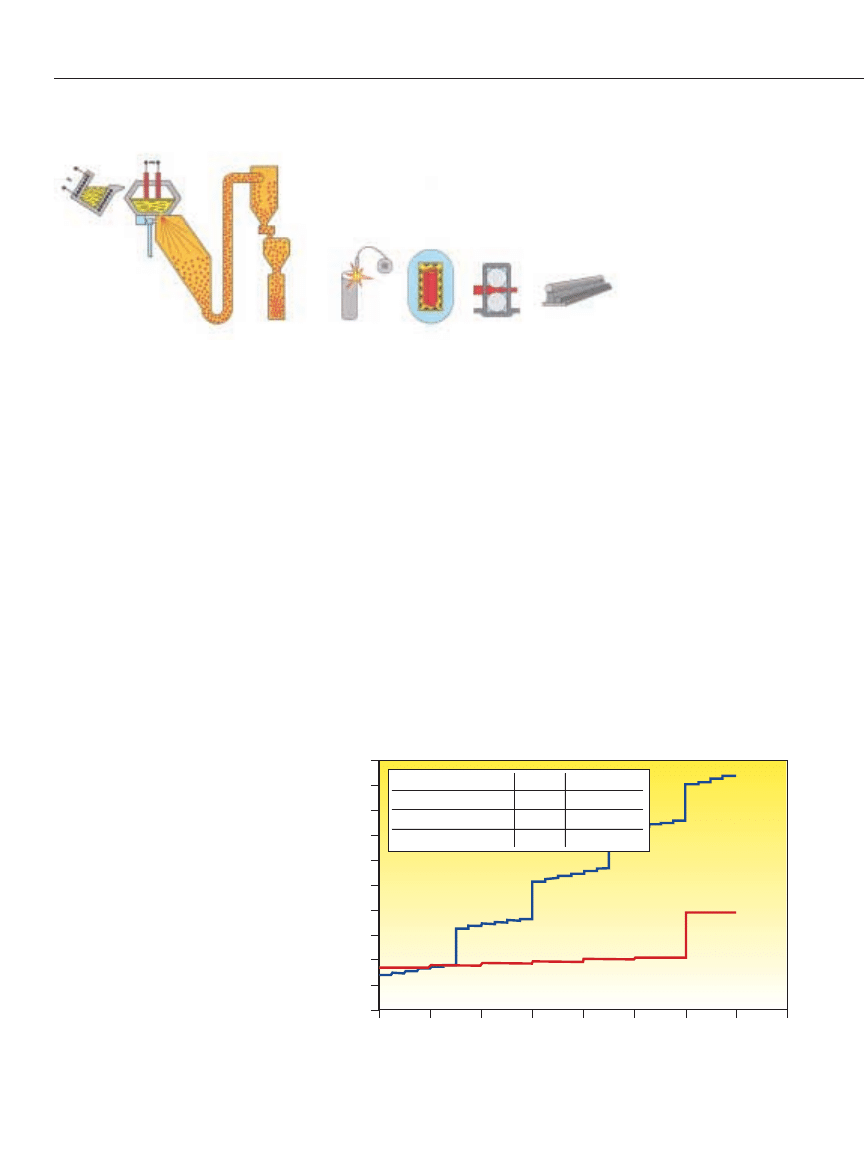
Fig. 1—Hot isostatic processing of packed powder, at 2100 F and at high pressures, com-
presses the powder into a dense billet, which then is rolled or forged to the desired bar size.
The Making of PM Tool Steels
5000
4500
4000
3500
3000
2500
2000
1500
1000
500
0
0
10,000
20,000
30,000
40,000
50,000
60,000
70,000
80,000
Number of parts produced
PM Steel, 4.0V
D2
To
tal cost (SEK)
D2
PM Steel, 4.0V
Tool life/regrind
25,000
100,000
Number of regrinds/tools 5
5
Total tool life
150,000
600,000
Fig. 2—The small increases in tool costs shown in the graphs represent regrind-
ing costs; the larger increases represent the cost of a new tool.
Tool Cost as a Function of Number of Parts Produced
Melting
Welding
Rolling
Bar products
Atomization
Capsule
filling
HIP/Hot
isostatic
pressing
w w w . m e t a l f o r m i n g m a g a z i n e . c o m
METALFORMING / JANUARY 2003
49
manufacturers used standard composi-
tions as starting points and then added
up to 10-percent vanadium with a bal-
anced amount of carbon to increase
carbide volume and hardness. This
greatly improved wear resistance while
maintaining good cracking resistance
compared with conventional grades.
Those early PM grades covered most
tooling requirements for many years,
but as application requirements evolved,
industry needed PM grades with more
specific property profiles. Over the last
decade this has led to the development
of new grades, mainly in two direc-
tions. First, manufacturers offer low-
alloyed grades containing one- to five-
percent vanadium, with optimized
compositions that further improve duc-
tility. These grades offer significantly
higher cracking and fatigue resistance,
in some cases approaching or even sur-
passing mold-quality S7, while offering
better wear resistance.
The second development: wear-
resistant grades trying to span the gap
between steels and cemented carbides.
These grades have vanadium content to
18 percent, giving them extremely high
wear resistance while maintaining a
cracking resistance better than conven-
tionally produced D2 and D3 steels.
And, tool-steel providers have devel-
oped new super-HSS alloy for the cut-
ting-tool market that can achieve hard-
ness of 70 HRC or slightly above.
Steel Selection
The higher the carbon and vanadium
content in a PM grade, the higher the
alloy’s wear resistance and the lower its
resistance to cracking and chipping.
Selecting the appropriate PM grade,
the following discussion assumes that
other factors that can cause failures have
been looked at and corrected. This would
include obvious design features that
can initiate cracks, and surface-finish
issues with special considerations for
remaining EDM layers and heattreatment.
• A stamper using conventional cold-
work grades such as D2 or D3 without
experiencing cracking or chipping prob-
lems can benefit from using almost any
Tooling
Technology
For these reasons, manufacturers of
PM tool steels have focused on reducing
nonmetallic inclusion content in the
alloys. A series of process developments
led to the introduction of a second gen-
eration of PM steels. Today’s second-
and third-generation PM steels contain
less than 10 percent of the inclusions
found in earlier PM alloys, with improved
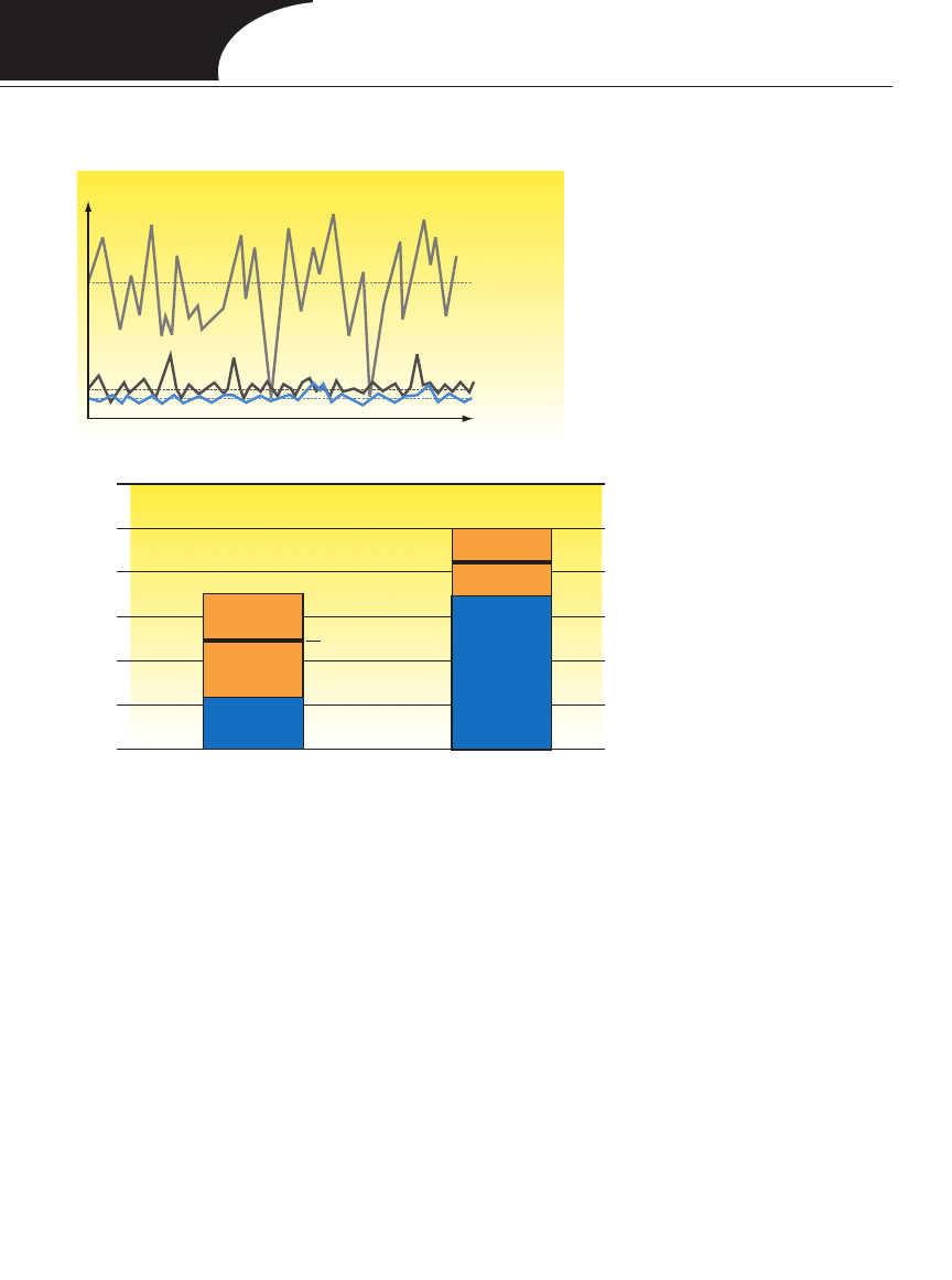
consistency from heat to heat (Fig. 3).
The increased cleanliness of the PM
steels has yielded significant improve-
ments in cracking and chipping resist-
ance, especially in the transverse direc-
tion. For example, as shown in Fig. 4,
the effect on four-percent-vanadium
PM tool steel in a blanking operation of
18Cr - 9Ni stainless steel, the improved
cleanliness of the tool steel significant-
ly increased average tool life and
reduced variation in punch life.
New Grades
Meet Specific Needs
Another area of development has
been the introduction of new PM grades
to cover more specialized tooling needs.
In the early years the grades were based
mostly on standard alloys. Steelmakers
produced grades of PM steels to improve
properties, such as HSS grades M3:2,
M4 and T15. On the cold-work side,
Number of inclusions
Number of tested bar samples
3
rd
Generation
2
nd
Generation
1
st
Generation
Variation
Average
tool life
12,000
10,000
8000
6000
4000
2000
0
Number of parts
4-percent V
PM tool steel
1
st
Generation
4-percent V
PM tool steel
2
nd
Generation
{
Process Perfected: Inclusion Content Minimized, Tool Life Increased
Second- and third-generation PM tool steels contain significantly fewer inclusions
than earlier alloys (top graph). Increased cleanliness yields improved cracking
and chipping resistance and increased tool life. The example above shows how
improved PM grades increase tool life when blanking stainless-steel strip.
Fig 3
Fig 4
50
METALFORMING / JANUARY 2003
w w w . m e t a l f o r m i n g m a g a z i n e . c o m

PM grade with a vanadium content
above five or six percent, to improve tool
life. In these applications, PM grades
will offer at least the same cracking
resistance while improving wear resist-
ance with correspondingly increasing
alloy content. The right choice of PM
alloys then depends on factors such as
how many parts have to be produced,
steel price, ease of machining and heat-
treatment. Because machinability
decreases with increasing alloying con-
tent, the metalformer must balance the
choice of grade against the cost of
machining and total number of parts
produced. This way, the stamper can
minimize overall tooling costs, includ-
ing the steel price, by not selecting a
grade with higher alloying content and
price than necessary.
• When a stamper experiences chip-
ping or cracking with grades such as D2
or A2, the job of selecting the appro-
priate PM tool steels becomes more
difficult. Factors in play include hard-
ness and thickness of the workpiece
material, tool-design complexity, and
the severity of the chipping and crack-
ing. Here, the experience of similar-
type tools can be of great help when
determining which grade and hardness
level to select. Typically, stampers find
that selecting a lower-alloyed PM grade,
with vanadium content of one to six
percent, works best. Here’s where the
second- and third-generation PM steels,
with their improved cracking resist-
ance, can offer the advantage of allow-
ing the customer to use a somewhat
higher-alloyed grade. This will improve
tool life by not sacrificing more wear
resistance than necessary.
This case illustrates the low cracking
resistance of traditional high wear-
resistant grades and how it can force the
tool user toward grades with very low
wear resistance. A PM grade can solve
both problems.
MF
Powder-Metallurgy Tool Steels
Case Study
To summarize the benefits of
changing from traditional grades to
PM tool steels, the following case
serves as a good example.
Tool type: Blanking tool
Hardness: Punch and die both
57-58 HRC
Work material strength: 78 ksi
Thickness: 0.39 in.
Surface condition: Hot rolled
Die clearance: 5 percent
Details for toolmaking:
Machinability: The PM grade is a
little worse than A2. Grindability:
Same as for D2.
Results:
Steel grade: A2
Tool life/regrind: 15,000 parts
Steel grade: 4.0V PM grade
Tool life/regrind: 58,000 parts
The tool life/regrind is almost four
times better with the PM grade.
D2 cannot be used for this applica-
tion because the tool chips
almost immediately after enter-
ing service.
w w w . m e t a l f o r m i n g m a g a z i n e . c o m
JANUARY 2003
51
Wyszukiwarka
Podobne podstrony:
16 197 208 Material Behaviour of Powder Metall Tool Steels in Tensile
Powder
4 PIM Powder Injection Molding
Powder Metallurgy
powdermeTALLURGY
Coating Methods, Powder Technology
Investigations of White Layer Formation During Machining of Powder Metallurgical Ni Based ME 16 S
ACTROL POWDER NATURALNY ANTYBIOTYK DLA TWOJEJ SKÓRY
POWDERWAY karta?nych?zpieczenstwa produktu
Makijaż permanentny brwi metoda hybrydowa, powder?fect
How To Make Black Powder And Other Explosives
Georgette Heyer Powder and Patch
Crimson powder
Preparation of garlic powder with high allicin content by using combined microwave–vacuum and vacuum
Calcium Hypochlorite powder tablet calculation
Chemical And Ballistic Properties Of Black Powder
Zastosowanie zawiesiny Wet Powder do ujawniania śladów daktyloskopijnych na wewnętrznych powierzchni
Swiss Black Powder
więcej podobnych podstron