
CRACK RESISTANCE OF HARDENED STEELS
AGAINST THERMAL SHOCK
H. Tabe
Tabe Consulting Engineer Office
1-26-27 Ebara-dai
Sakura-shi Chiba-ken
285-0825 Japan
Abstract
Hardened tool steels require not only ordinal mechanical properties such as
high strength, high ductility, high notch toughness, high wear resistance, etc.,
but also crack resistance property against thermal shock such as grinding,
EDMing, friction and repeated thermal conduction in use, in order to get
longer tool lives.
To test thermal shock resisting property, friction followed by water cooling
to the rubbed surface was employed. In this one-cycle thermal shock test, low
carbon steels were smaller in depth of maximum crack than high carbon steels
in the same hardness levels, which means that lower carbon steels can pro-
vide higher thermal shock resistance on top of better mechanical properties,
compared with higher carbon steels.
Using the same testing method, but with 100 times repeated cycles, the
crack initiation property of hardened steels was also tested. From the view-
point of simultaneous crack occurrence property, which seems to be important
to mitigate the stress concentration with thickly populated initial cracks and
prolong the crack propagation afterward, the test results were summarized as
below.
The simultaneous crack occurrence property is affected by firstly mi-
crostructure, which means that martensite is better than bainite and pearlite
in this property. Secondly, the hardness of steels affects the property, and
in the carbon range of 0.6-1.2% of 1%Cr-Mo steels, the simultaneous crack
occurrence property is improved with hardness. The third factor to affect
the property is carbon content, and in carbon range of 1.2-2.1% of 1%Cr-Mo
847

848
6TH INTERNATIONAL TOOLING CONFERENCE
steels, the simultaneous crack occurrence property is improved with carbon
content, probably because bigger carbides provide embryos of cracks.
Keywords:
Thermal shock crack, Heat check crack, Simultaneous crack occurrence prop-
erty
INTRODUCTION
Tool steels are commonly required both some level of hardness against
wear and plastic deformation as well as ductility and toughness against chip-
ping and gross cracking [1].
Through many trouble shooting investigations, quite a few chipping and
cracking troubles are originally caused by heat affected zones and cracks
produced by thermal shock such as grinding and EDMing in tool making
stages, and friction heat and thermal conduction in tool using stages [2, 3].
One of the weak points of tool steels is susceptibility to thermal shock.
Unlike soft steels, hardened steels with higher hardness are generally sus-
ceptible to thermal shock and tend to have thermal shock damages. Talking
about thermal shock, there are two types: one is single cycle thermal shock
and the other is repeated cycle one. And both types are quite often to occur
in tool steels.
So hereby, firstly single cycle thermal shock is handled, dealing with the
relation of maximum thermal shock crack in between low carbon steel and
high carbon steel. And secondly, repeated cycle thermal shock damages are
tested and discussed in terms of simultaneous crack occurrence property of
initial crack in steels.
THERMAL SHOCK TEST MACHINE
To give severe thermal shock with rapid heating up and rapid cooling
down, the friction thermal shock tester [4] was used. The tester, Fig. 1, has
a mechanism of friction heating up by pushing a specimen with a rotating
steel wheel of 1055 rpm and 1300 N of loading for 30 seconds, and following
water spray to the rubbed surface of the specimen, in case of single cycle
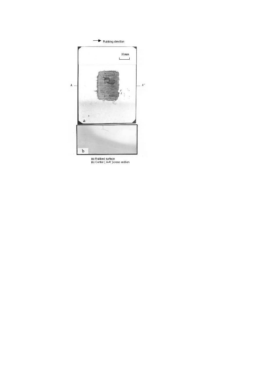
thermal shock test. An example of the rubbed surface is Fig. 2. In case
of repeated cycle thermal shock test, the same machine was used with disc
rotating speed at 450 rpm, loading at 130 N, rubbing for 5 seconds and water

Crack Resistance of Hardened Steels Against Thermal Shock
849
Figure 1.
Thermal shock test machine by friction, followed by water spray.
Table 1.
Chemical composition and heat treatment of test materials
Chemical composition (weight %)
Steel grade
C
Si
Mn
P
S
Cr
Mo
Microstructure
Hardness
A
0.39
0.60
0.33
0.016
0.013
5.09
0.34
Martensite
42–53 HRC
B
0.90
0.52
0.25
0.011
0.008
5.10
0.34
Martensite
42–53 HRC
C
0.1–
2.6
0.47–
0.55
0.03–
1.02
0.012–
0.016
0.010–
0.018
0.94–
1.15
0.42–
0.45
Martensite
19-46 HRC
D
0.82
0.61
1.56
0.028
0.005
1.87
0.28
Martensite,
40-48 HRC
Bainite,
Perlite
spraying to rubbed surface for 5 seconds per one cycle. This thermal cycle
was repeated just 100 times to watch initial cracks.
SINGLE CYCLE THERMAL SHOCK TEST
INFLUENCE OF CARBON CONTENT ON CRACK
DEPTH
The specimens used for this test are A grade ( 0.4%C-5%Cr-Mo steel )
and B grade ( 0.9%C-5% Cr-Mo steel ) in Table 1. They are hardened and
tempered to various hardness levels from 42 to 53 HRC, using tempering
temperatures from 450
◦
C to 650
◦
C .
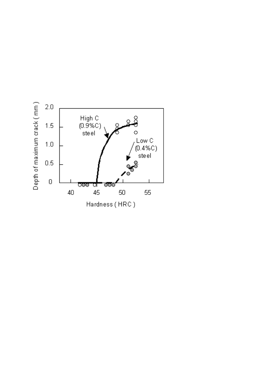
The test result is shown in Fig. 3. According to this figure, 0.9%C steel
is deeper in the maximum crack than 0.4%C steel, with more than 2 times
crack depth than that of 0.4%C steel. Regarding crack occurring hardness,
0.9%C steel starts at 45 HRC, and 0.4%C steel at 48 HRC, which also means
850
6TH INTERNATIONAL TOOLING CONFERENCE
Figure 2.
A example of specimen after single thermal shock testing.
that 0.9%C steel is more susceptible to thermal shock cracking than 0.4%C
steel.
DISCUSSION ON THERMAL SHOCK CRACK
RESISTING PROPERTY
As a conclusion of this one cycle thermal shock test, low carbon steels are
more crack resistant than high carbon steels, provided using hardness is the
same. On the other hand low carbon steels can have higher hardness than
high carbon steel, provided their thermal shock crack resistance is set at the
same level.
Crack Resistance of Hardened Steels Against Thermal Shock
851
REPEATED CYCLE THERMAL SHOCK TEST
PRELIMINARY TEST
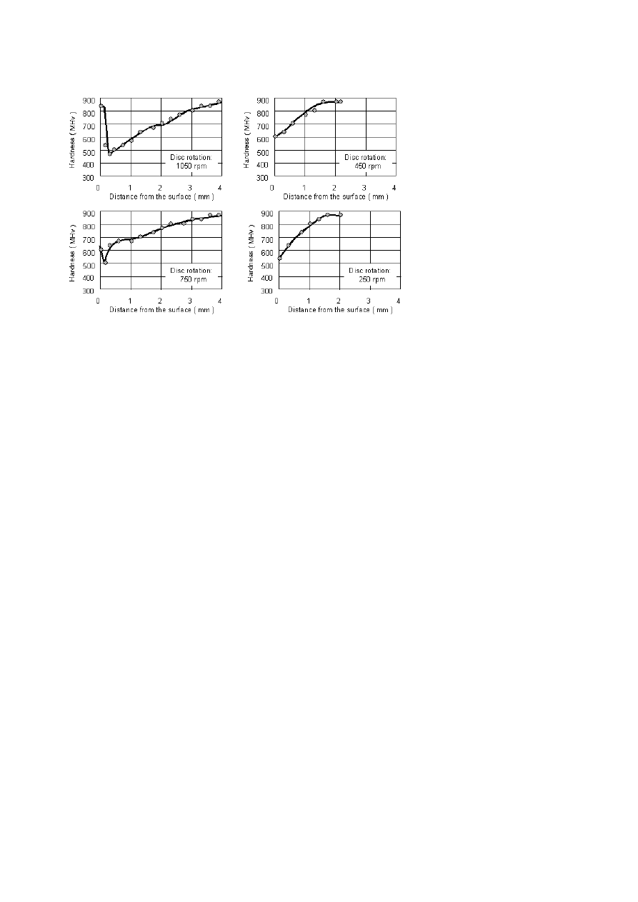
A preliminary test was executed to get a suitable condition for repeated
cycle thermal shock testing. By changing the rotation of the disc from 1055
to 250 rpm with 5 seconds of friction, followed by 5 seconds of water spray
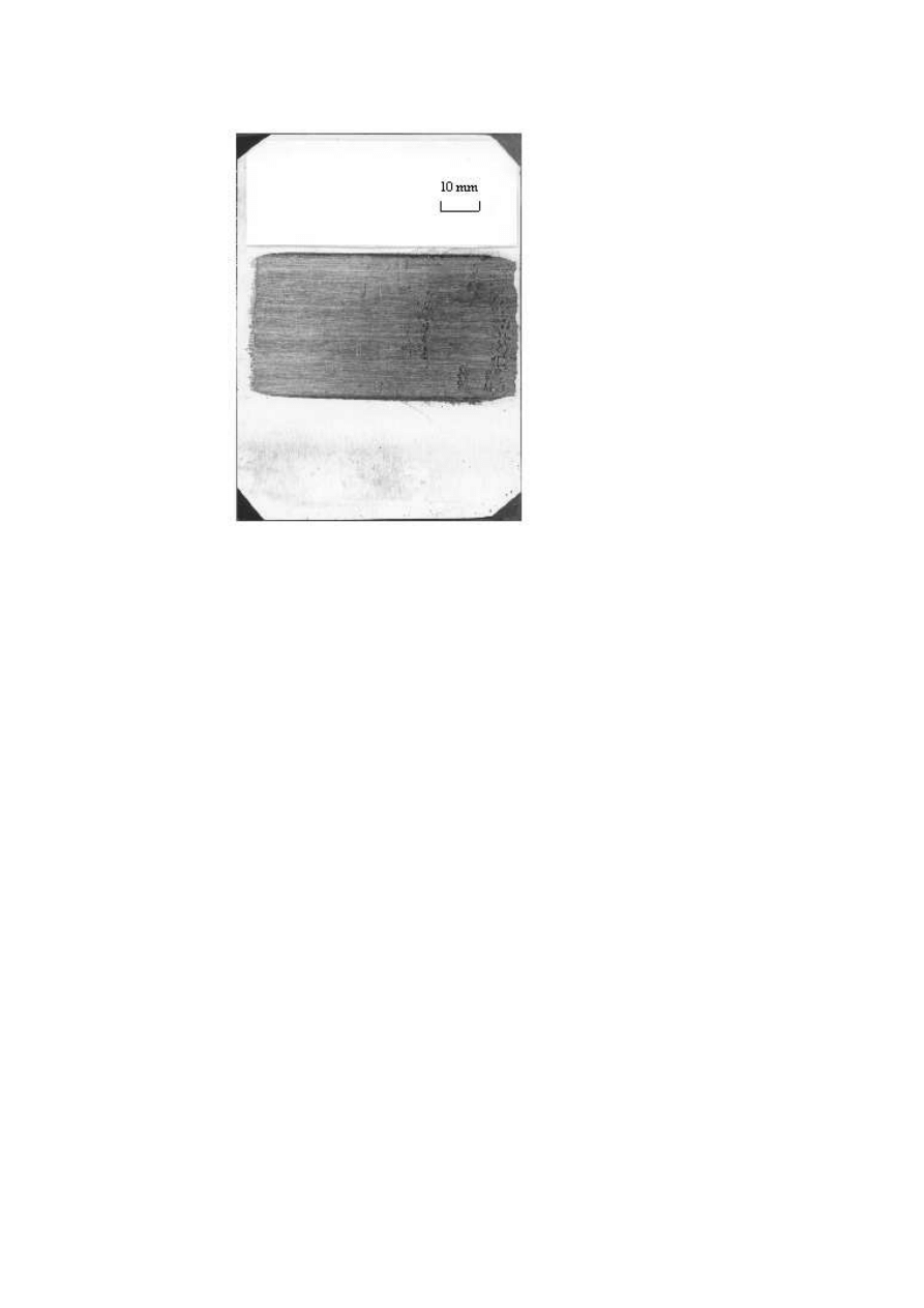
cooling on the rubbed surface, the specimens tested (An example is Fig. 4)
were cut at the center line along the friction direction and their hardness
distribution were measured from the surface to inside. The test result is
Figure 3.
Difference of thermal shock crack resistance between low C steel and high C
steel.
as shown in Fig. 5. According to it, in case of 1055 rpm of disc rotation
there exists rehardened zone, and in case of 750 rpm, imperfect rehardened
zone. In case of 450 rpm and 250 rpm there exists only tempered zone. In
852
6TH INTERNATIONAL TOOLING CONFERENCE
Figure 4.
B steel specimen after repeated thermal shock test.
this test 450 rpm was employed. It seems that this testing condition almost
corresponds to 650
◦
C in maximum surface temperature, which is one of the
representative surface temperatures of hot working tools.
An example of specimen after testing is shown in Fig. 4, in the center
of which there is a black band rubbed to horizontal direction by the rotating
disc.
Some cracks can be seen on the rubbed surface. The specimen tested
are cut at the center line along the rubbed direction, on the cross section of
which is observed and measured the number of cracks and the length of each
crack.
Crack Resistance of Hardened Steels Against Thermal Shock
853
Figure 5.
Hardness distribution from the surface after 1000 times of friction, followed by
water spray.
RELATION BETWEEN CARBON CONTENT OF STEEL
AND DAMAGE BY REPEATED THERMAL SHOCK
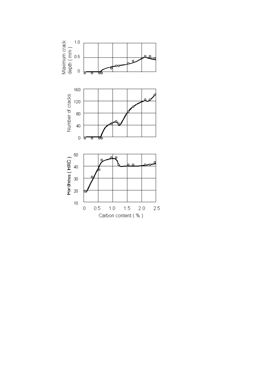
As specimens tested, C grade in Table 1 was used.
All the specimens tested were so-called 1%Cr-0.4%Mo steel, but their car-
bon contents are scattered from 0.1% to 2.6%. All of them were heat treated
with the same thermal cycles (900
◦
C , oil quenched and 560
◦
C tempered) to
get scattered hardness from 16-46 HRC. The test result is shown in Fig. 6.
According to the figure, firstly below 0.6%C no cracks can be observed,
though its hardness is as high as 40 HRC at 0.6%C. Beyond 0.6%C, as carbon
content increases, maximum crack depth increases as a whole.
In carbon range from 0.6%C to 1.2%C, as carbon content increases, num-
ber of cracks changes with good relation to the hardness of the steels. How-
ever, from 1.2%C to 2.1%C, the number of cracks increases rapidly as carbon
content increases, though hardness remains almost the same .
854
6TH INTERNATIONAL TOOLING CONFERENCE
Figure 6.
Results of repeated thermal shock testing of C steel.
RELATION BETWEEN MICROSTRUCTURE AND
DAMAGE BY REPEATED THERMAL SHOCK
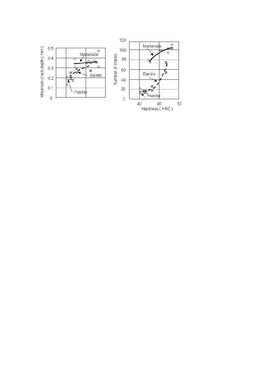
The steel grade D in Table 1 was used for this test. This 2%Cr- Mo type of
steel was heat treated to martensite, bainite and pearlite by cooling 950
◦
C to
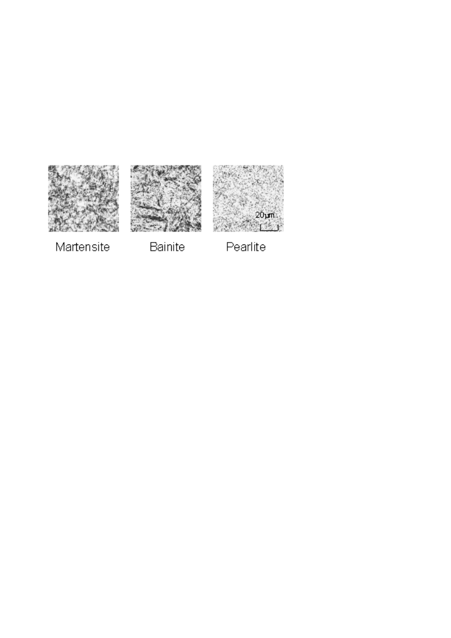
Crack Resistance of Hardened Steels Against Thermal Shock
855
the temperature of 20
◦
C , 300
◦
C and 550
◦
C for transformation and then by
tempering with temperatures from 500
◦
C to 570
◦
C to get hardness scattered
from 40 to 48 HRC. Examples of microstructure obtained are shown in
Fig. 7. The test result is summarized in Fig. 8 According to the figure,
by comparing martensite and bainite in the same hardness level, firstly it
can be said that though martensite is deeper in maximum crack depth than
bainite, martensite has more number of cracks than bainite. Pearlite is low
in hardness level as its nature and seems to be at extension position of bainite
in terms of both maximum crack depth and number of cracks.
Figure 7.
Microstructures of B steel specimens for thermal shock testing.
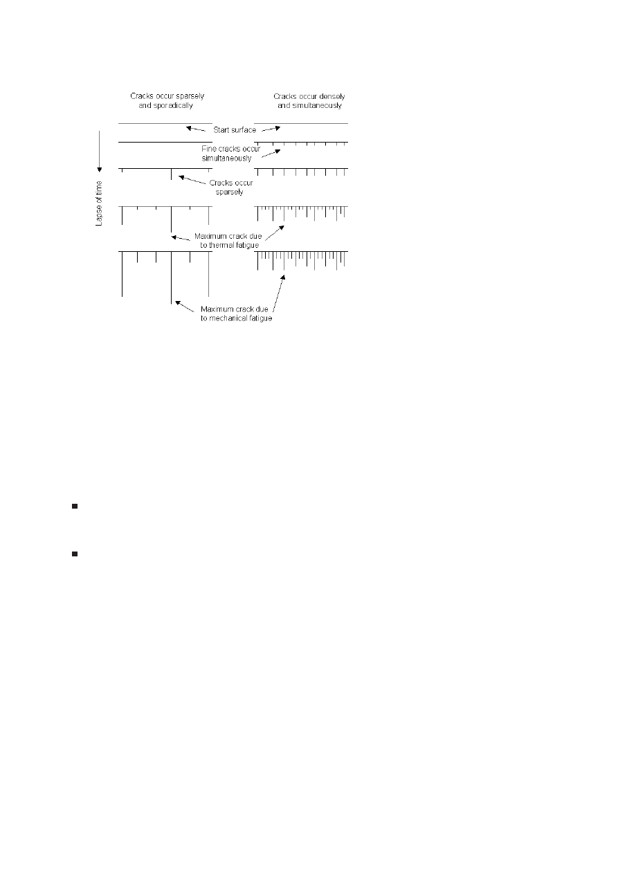
DISCUSSION ON SIMULTANEOUS CRACK
OCCURRENCE PROPERTY
In this study, initiation of cracks in very early stage of repeated thermal
shock process was investigated. When very initial stage of crack occurrence
is discussed, the simultaneous crack occurrence property seems to be worth
being paid much attention. Figure 9 is proposed as two types of initial
crack patterns. In case the tool material has so-called simultaneous crack
occurrence property as shown in right side of Fig. 9, it will be difficult for
cracks to propagate afterward, because of less stress concentration due to
thick populated cracks in early stage.
In the first test using various carbon contents of 1%Cr-Mo steels, in carbon
range from 0.6 to 1.2%C, hardness is mostly affecting the the simultaneous
856
6TH INTERNATIONAL TOOLING CONFERENCE
Figure 8.
Relation between microstructure and heat check property in D steel.
crack occurrence property rather than carbon content. In carbon range from
1.2 to 2.1%C, carbon content is mostly affecting the property rather than
hardness, which is remaining at almost same level.
This can be construed that the increased number of bigger carbides will
provide the embryos of initial cracks. And it can be said that as the sizes
of the bigger carbides increases with the number of bigger carbides, the
maximum crack depth increases.
In the second test using martensite , bainite and pearlite, the tendency that
martensite has higher simultaneous crack occurrence property than other
two microstructures can be seen clearly.
There has been done many heat checking tests concerning hot work tool
steels and many kinds of results have been obtained [1, 5, 6, 7, 8]. Test
results might be different from each other, probably because of difference
of testing method.
Generally in some heat checking tests in the past, the heating up speed
was very slow. In this test, friction mechanism is employed for rapid heating
up and steep gradient. So it can be said that mechanism or method of heat
checking test has much to do with the test result and resultant conclusion.
Crack Resistance of Hardened Steels Against Thermal Shock
857
Figure 9.
Two types of heat checking processes, one with sparse and sporadic cracks and
the other with dense and simultaneous cracks.
Crack propagation from the cracks generated by repeated thermal shocks
has been generally discussed from the viewpoint of ductility and the tough-
ness of the steel. However, simultaneity of cracks occurrence should also
be taken much into consideration when crack propagation is discussed.
CONCLUSION
Through this thermal shock test using friction mechanism, the following
test results were found.
The thermal shock tester was effective to get quantitative damage data
such as depth of the crack, and was available for both one cycle thermal
shock and repeated cycles ones.
In one cycle thermal shock test to 0.4C% and 0.9%C-5%Cr-Mo steel,
the high carbon steel (0.9%C) has cracks beyond hardness of 45 HRC,
while the low carbon steel (0.4%C) has cracks beyond 48 HRC. And

858
6TH INTERNATIONAL TOOLING CONFERENCE
in hardness area beyond 48 HRC and below 53 HRC, the high carbon
steel (0.9%C) is more than 3 times deeper in crack depth than the low
carbon steel ( 0.4%C ).
In the repeated cycle thermal shock test, the idea of simultaneous
crack occurrence property of steels is proposed and its importance is
stressed.
By the repeated cycle thermal shock test using various carbon contents
of 1%Cr-Mo steels of 560
◦
C tempered martensite, it was found that the
simultaneous crack occurrence property is firstly affected by hardness,
and secondly by carbon content. and thirdly by microstructure.In
carbon range from 0.6 to 1.3%C, hardness is mostly affecting the the
simultaneous crack occurrence property rather than carbon content.
In carbon range from 1.3 to 2.2%C, carbon content is mostly affecting
the property rather than hardness, probably because increased number
of bigger carbides will provide the embryos of initial cracks. On top of
hardness and carbon content, microstructure is the third factor to affect
the simultaneous crack occurrence property. By the repeated cycle
thermal shock test using various hardness of 2%Cr-Mo steels tempered
to martensite, bainite and pearlite, it was found that martensite provide
more initial cracks than bainite and pearlite.
Tempered martensite is known to show good performances in actual
hot tool applications. That seems to be attributable to not only better
ductility and toughness but also better simultaneous crack occurrence
property, than other microstructures.
REFERENCES
[1] R. JERVIS, B. JOHANSON, L-A NORSTROM and O. SANDBERG, in Proceedings of
the 2nd International Conference on New Materials Processes Experiences for Tooling,
, September 7-9, 1992 , edited by H. Berns etc., p. 49.
[2] H. TABE, in Proceedings of an International Conference on Tool Steel for Dies and
Molds, Shanghai, China, April 14-16 1998, edited by Xu Luoping etc., p. 157.
[3] H. TABE, in Proceedings of the 5th International Conference on Tool Steels in the Next
Century, Leoben, Austria, Sep.29-Oct.1 1999, edited by Franz Jeglitsch etc., p. 115.
[4] H. TABE, in Proceedings of the 1st International Conference on Tool Materials for
Molds and Dies, St.Charles, Illinois, Sep.30-Oct.2 1987, edited by G. Krauss and H.
Nordberg, p. 315.

Crack Resistance of Hardened Steels Against Thermal Shock
859
[5] L. ELIASSON and O. SANDBERG, in Proceedings of the 2nd International Conference
on New Materials and Processes for Tooling, Sep.6-8 1989, p. 3.
[6] Die Heat check Research Group in Japan Heat Treatment Technology Association,
Presentation meeting on Joint Research Result, March 10 1995, p1-187.
[7] Research Group in Japan Heat Treatment Technology Association on Improvement of
Surface of Hot Work Tool Materials, Presentation meeting on Joint Research Result,
March 12 1998, p1-198.
[8] Research Group in Japan Die and Mold Technology Association on Improvement of
Surface of Hot Work Tool Materials, Steps to improve Lives of Hot Work Dies, edited
by the group, July 26 2001, p1-345.
Wyszukiwarka
Podobne podstrony:
25 339 348 Development Trends of Corrosion Resistant Plastic Mould Steels
37 509 524 Microstructure and Wear Resistance of HSS for Rolling Mill Rolls
36 495 507 Unit Cell Models for Thermomechanical Behaviour of Tool Steels
78 1101 1109 Industrial Production of Tool Steels Using Spray Forming Technology
86 1225 1236 Machinability of Martensitic Steels in Milling and the Role of Hardness
81 1147 1158 New Generation of Tool Steels Made by Spray Forming
70 1003 1019 Influence of Surface Engineering on the Performance of Tool Steels for Die Casting
5 49 62 The Influence of Tramp Elements on The Spalling Resistance of 1 2343
45 625 642 Numerical Simulation of Gas Quenching of Tool Steels
37 509 524 Microstructure and Wear Resistance of HSS for Rolling Mill Rolls
In vitro corrosion resistance of titanium made using differe
Antifungal resistance of C glabrata
Pathogenesis and antifungal drug resistance of C glabrata
więcej podobnych podstron