T
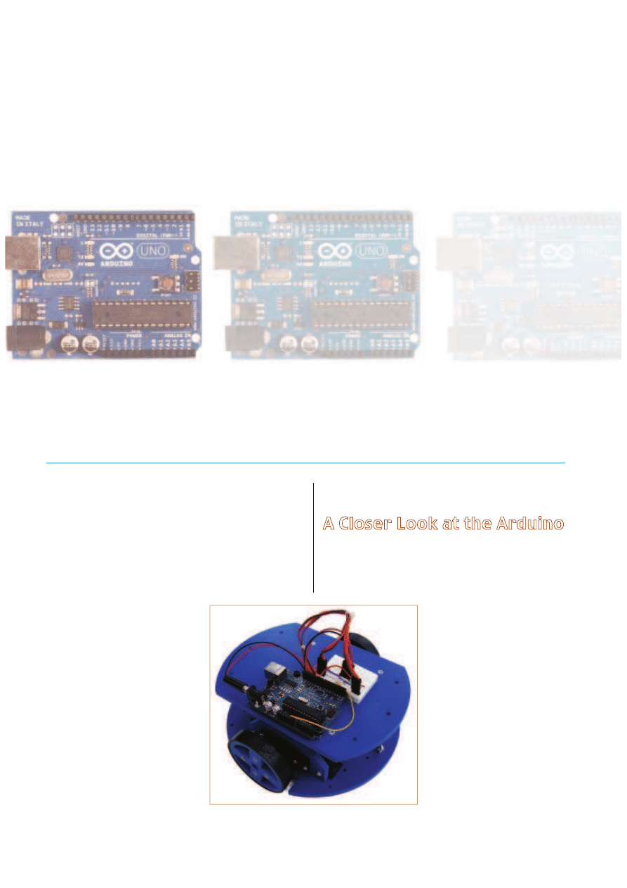
hat’s the idea behind the ArdBot shown in Figure 1. It’s
a low cost, expandable, and easy to build mobile robot
based on the popular Arduino microcontroller. Total cost
of construction is under $85, and even less if you already have
some of the common components, like RC servo motors
modified for continuous rotation and a solderless breadboard.
The past two installments of this series introduced the
Arduino controller and the ArdBot chassis. Part 1 covered the
Arduino and why this $30 board is fast becoming a favorite
among experimenters the world
over. Part 2 detailed the mechanical
construction of the ArdBot — a
seven inch diameter desktop rover
powered by replaceable or
rechargeable batteries and twin RC
servo motors.
This time, you’ll learn more
about the Arduino and its
programming. The Arduino leverages a
number of well supported open source
projects, and mashes them into a
convenient integrated development
environment (IDE) that’s simple to
install and easy to use. In future
articles, you’ll apply what you learn
here to the ArdBot, including
writing your own motor control functions, responding to
sensor feedback, and more.
A Closer Look at the Arduino
Arduino is more a concept than it is a specific product.
Since its introduction in 2005, the Arduino microcontroller
board has gone through many permutations, and even
today there are over half a dozen “official” Arduino boards
that vary in size, shape, and
capabilities — add to this literally
dozens of clone Arduinos that go by
other names like Freeduino,
Boarduino, and many others.
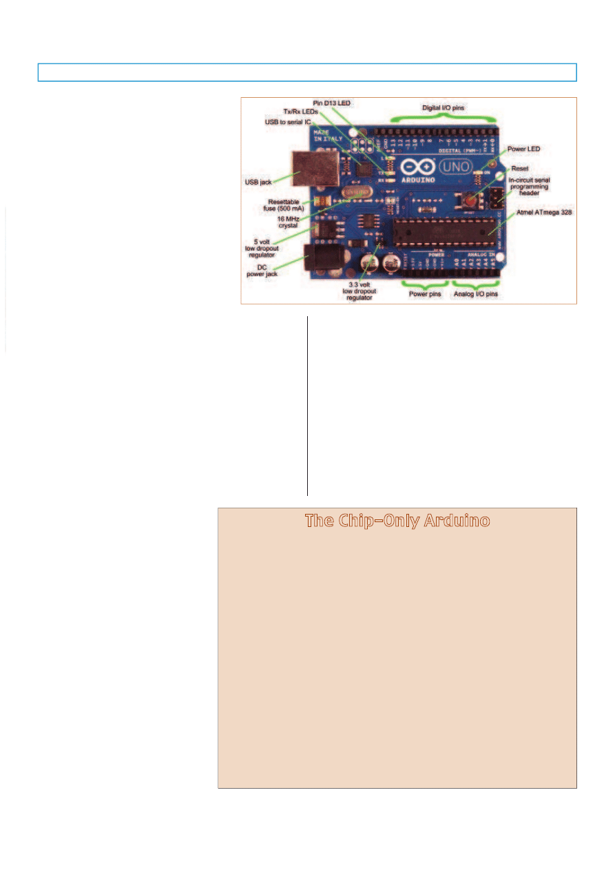
Figure 2 shows the Uno — one
of several Arduino boards — but one
that encapsulates the core set of
Arduino functionality. It’s the latest
version of the most popular Arduino
design which features a low cost
Atmel ATmega328 microcontroller
mounted on a handy “stackable”
development board. There are other
Making Robots
With The
Part 3 -
Inside the
Arduino
By Gordon McComb
60
SERVO 01.2011
FIGURE 1.
The ArdBot, with Arduino
microcontroller and mini solderless
breadboard for experimenting.
You can construct a fully autonomous programmable robot for less than
the cost of dinner and a movie for two. Mind you, I’m not suggesting one
over the other — just pointing out that robots don’t have to be expensive
or difficult to build. It might have been true in the past, but it’s not now.
A
rduino
worldmags
versions of the Arduino — bigger and
smaller — but it’s the 2-1/8” by 2-3/4” Uno
that most people use, and the one selected
for the ArdBot. (If you already have an
earlier version Diecimila or Duemilanove,
then those are okay, too, as long as you use
version 0017 or later of the Arduino IDE.)
Main points of interest of the Arduino
Uno include:
• The ATmega328 microcontroller,
running at 16 MHz. The board uses the
DIP version of the ATmega328 so that if
you “let the smoke out” of the thing, you
can easily replace just the chip, rather than
buy a whole new Arduino board.
• Reset pushbutton. Press to reset the currently running
program.
• Integrated USB-to-serial communications, for both
downloading programs from your PC and for serial
communications back to the PC for debugging and
monitoring. The USB link includes a 500 mA resettable
fuse to guard against possible damage caused by a
wayward Arduino to the USB ports on your PC. When
plugged into a USB port, the Arduino takes its power
from it. With USB 2.0, drive current is limited to 500 mA,
depending on the port design.
• DC power jack (2.1 mm, center positive) for use with
an external power source. Recommended voltage
range is 7-12 volts.
• Low dropout regulators for 5V
and 3.3V. The five volt regulator
provides up to 800 mA of current;
the 3.3 volt regulator provides up to
50 mA. Connection pins are
provided for both the 5V and 3.3V
regulated outputs. You can use these
pins to power low current
components such as ultrasonic
sensors or accelerometers.
• Indicator LEDs for power, serial
transmit and receive (labeled Tx and
Rx), and digital pin 13 (labeled L).
• Six-pin in-circuit serial programming
(ICSP) header. This provides a
standard connection with external
programmers for the Atmel AVR
microcontroller chips.
• Six analog input/output (I/O) pins
and 14 digital I/O pins. The analog
pins connect to an internal ten-bit
analog-to-digital converter (ADC),
letting you read voltages from
sensors and other devices. All I/O
pins can be used as digital outputs, and can sink or
source up to 40 mA.
• Power pins to provide external access to the
unregulated and regulated power supplies.
Let me pause here to point out that the ATmega328
on the Uno board isn’t an empty chip; it contains a small
bootloader program for use with the Arduino development
editor. The bootloader assists in the download process. You
can add the bootloader yourself (instructions are on the
arduino.cc
website), or you can buy a replacement
ATmega328 with the bootloader preinstalled.
Figure 3 shows the pin-out diagram of the 28-pin
ATmega328. The labels on the inside of the chip are the primary
function names for each of the pins. The labels outside in
www.servomagazine.com/index.php?/magazine/article/january2011_McComb
FIGURE 2.
Pictorial overview of the main
points of interest on the Arduino Uno
microcontroller board.
SERVO 01.2011
61
While manufactured Arduino boards
are hardly expensive, you can go even
cheaper by using the Uno as a
programmer. Once you’ve downloaded
your sketch, remove the ATmega328 chip
and transplant it into a solderless
breadboard or other circuit. The chip runs
under five volts (4.5V minimum, 5.5V
maximum), and only needs a 16 MHz
crystal and two 22 pF capacitors for
operation. You can even do away with the
caps if you use a 16 MHz three-pin
resonator, and don’t need the extra
precision of a crystal oscillator.
Use an IC extractor tool to prevent
damage to the ATmega328 pins when you
remove it from the Arduino board. The
tool grips the ends of the chip and allows
you to pull it straight out of its socket.
There isn’t even an absolute
requirement that you use an ATmega328
with the Arduino bootloader preinstalled.
You can use the Arduino development
environment and download your
programs directly into the chip. This
restores the Flash memory space
previously taken up by the Arduino
bootloader. It also avoids the
several seconds’ delay that occurs when
the Arduino is first powered up; this delay
is caused by the bootloader waiting to see
if a new program is about to arrive.
Programming without the bootloader
requires suitable hardware, such as the
Atmel STK500, AVR-ISP, or a homebrew
parallel port programmer. The Arduino
Uno has a suitable in-circuit serial
programming (ICSP) header already on
it. Just attach the six-pin cable from your
programmer to the ICSP header on the
Arduino.
Just so you know, serial programming
is just one method of burning software
into an AVR microcontroller. Many stand-
alone programmers like the STK500 also
support what’s known as
high-voltage
programming
which permits resetting certain
software fuse bits. These bits control
special behaviors of the chip, and are
documented in the AVR datasheets.
The Chip-Only Arduino
worldmags
worldmags
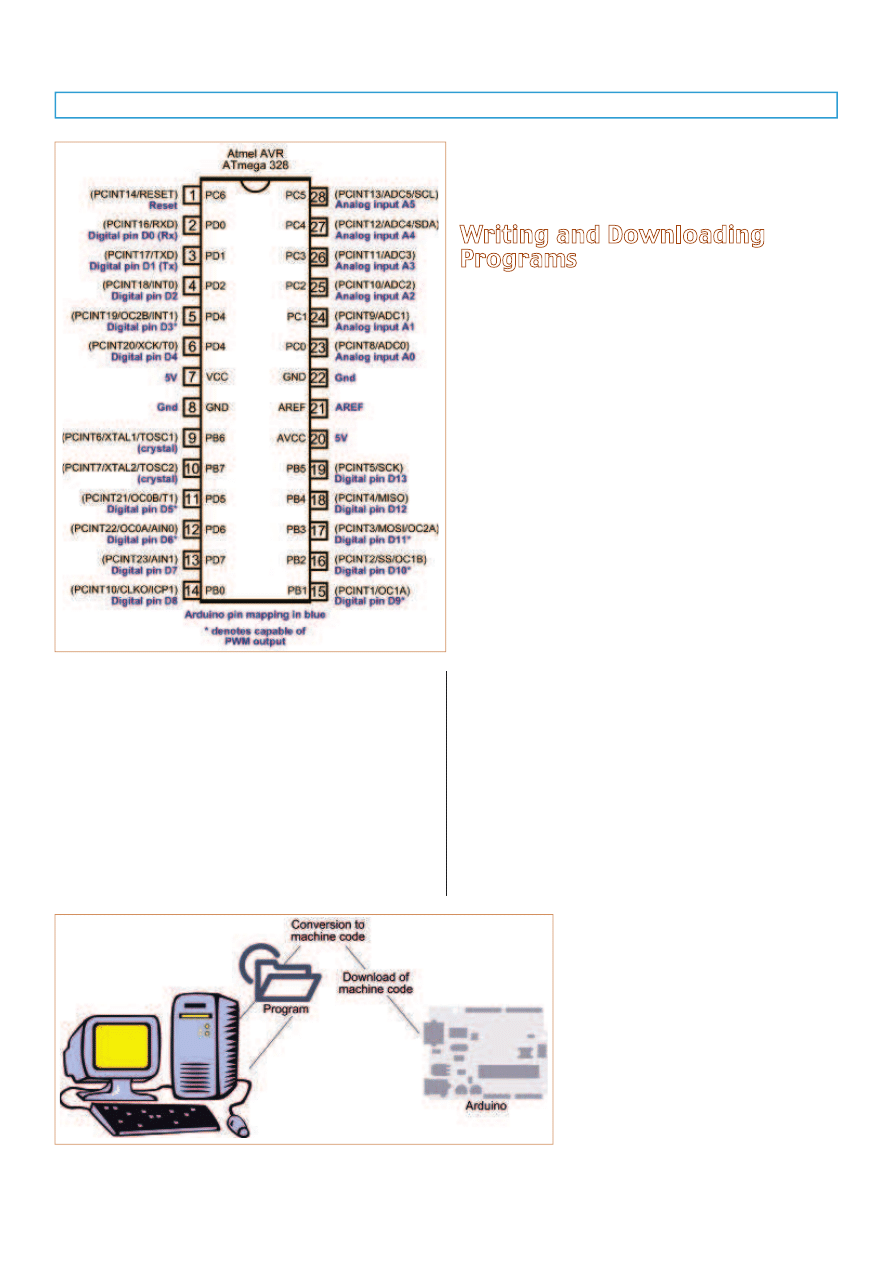
parentheses are alternative uses — if any — for the pins.
For example, pin 9 — labeled PB6 (for Port B, bit 6) — is
also used as a general-purpose I/O. In addition, it’s used as one of
two connection points for an external oscillator. As the Arduino
uses a crystal oscillator connected to this pin — as well as pin
PB7 — neither of these are available for use in your programs.
Also shown in Figure 3 is pin mapping between the
Arduino and the ATmega328. It’s important to remember
that the pin numbers are not the same between the two.
Pin 12 on the ATmega328 is actually mapped to digital pin
D6 on the Arduino. Pin mapping is not something you need
to worry about in typical Arduino programming, but it’s
nice to know what leads to where.
Writing and Downloading
Programs
If you’ve used any kind of microcontroller, you know
the process of programming it involves three steps: write
the program; compile the program; and run the program
(see Figure 4). The Arduino is no different, except that it
refers to its programs as sketches.
Sketches are written in a programming language very
similar to C. In fact, it is C (more accurately C++), but with
some simplifications to make it easier for newcomers to master
the system. If you’ve ever looked at a C/C++ program and
felt your eyes glazing over because of the obtuse appearance
of the code, you don’t have to worry about that with the typical
Arduino sketch. The Arduino is designed for beginners in mind,
but still provides power and flexibility for more advanced users.
Taken indepth, the three steps of writing and
downloading Arduino sketches are:
1. Develop your sketch on your PC. The Arduino comes with
a Java-based IDE that includes a fully featured text editor.
It supports syntax highlighting and coloring (different parts
of code are shown in different colors), but doesn’t give you
popup hints or keyword suggestions — like Microsoft’s
Intellisense. If you’re already familiar with another program
editor like Eclipse or SEPY, you can use it instead. The file
format for Arduino sketches is plain ASCII. (Even though SEPY
is intended for programming ActionScript — the language
used to create Adobe Flash applications — it inherently
understands most of the C syntax used in Arduino sketches.)
2. Once written, sketches must be compiled which in Arduino-
land is referred to as verifying. During the compile/verify
phase, any errors are flagged and noted at the bottom of
the Arduino editor window. The compiling process includes
building the sketch from component files. An Arduino sketch
is not in itself completely compatible with C; for one thing,
there’s no main() function which is required to tell the compiler
where the program is supposed to begin.
In actuality, it’s still there, under the hood.
When you compile your sketch, the
main() function is added to the program
for you, along with some additional code.
3. The compiled program is downloaded to
the Arduino via a USB cable. The download
process is automatic; the bootloader
program residing in the Arduino detects
when a new sketch is arriving. It performs
the necessary steps of first erasing the
old sketch in memory — if present — then
accepting the new one. Once downloaded,
the sketch starts automatically.
When you download a compiled
62
SERVO 01.2011
FIGURE 3.
Pin-out diagram of the Atmel ATmega328 chip with
the pin mapping to the Arduino I/O lines.
FIGURE 4.
Programs (sketches) are developed on your PC,
compiled to a machine-readable format, then downloaded to
the Arduino via USB.
worldmags
worldmags
worldmags
sketch to the Arduino, it is stored in 32K bytes of Flash
memory inside the ATmega328. This memory is the same
type used in solid-state USB drives, and has a lifetime of over
10,000 read/write cycles. Through the ATmega328, the
Arduino also supports 1K bytes of electrically erasable non-
volatile EEPROM (data survives after power-down) and 2K
bytes of RAM. Data in RAM is volatile; it’s lost when power
is removed from the Arduino.
Arduino Architecture
and Memory
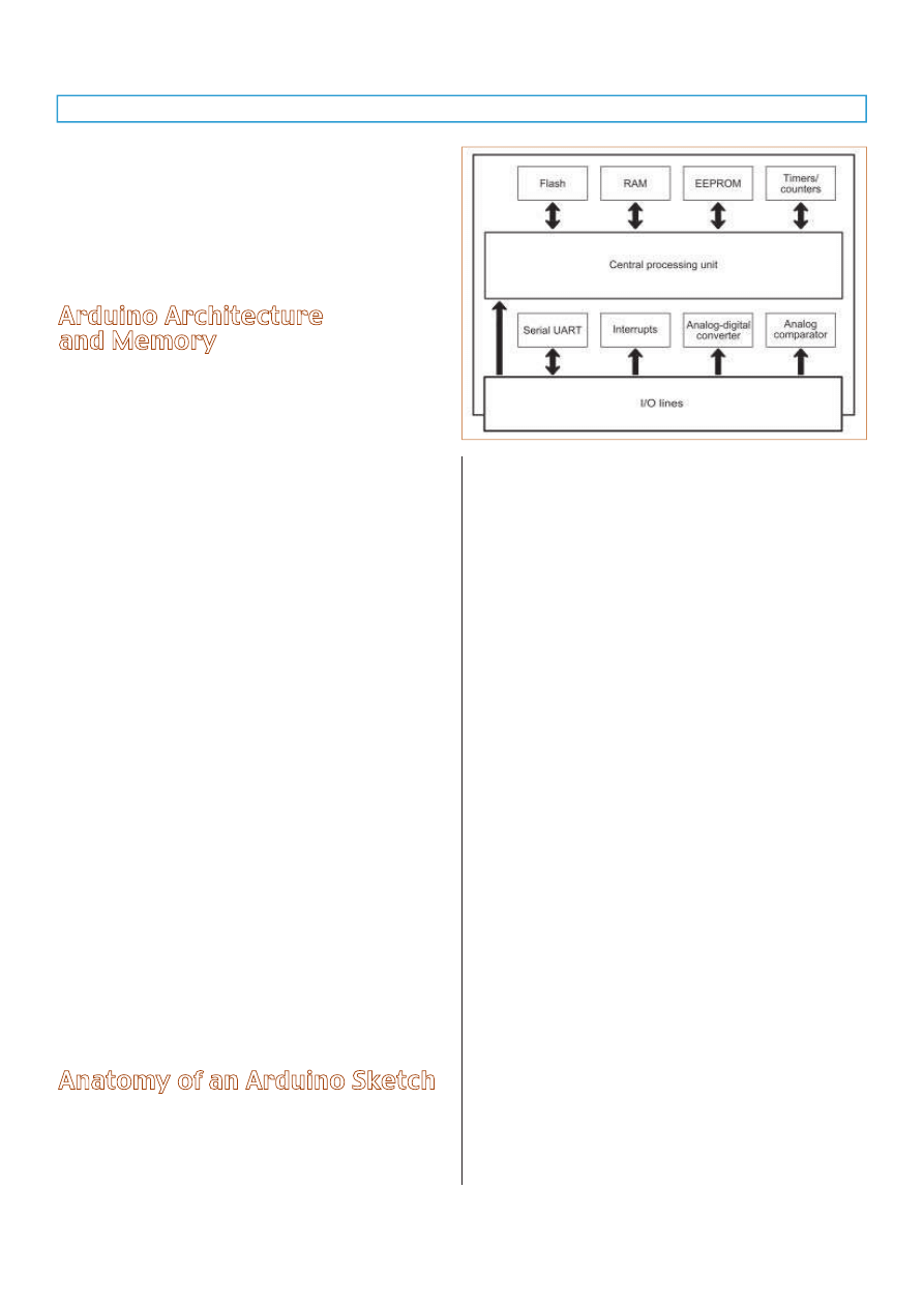
Figure 5 shows a simplified block diagram of the
ATmega328 used in the Arduino. In center stage is the
central processing unit, or CPU. This piece is what runs your
downloaded sketches, performing all the number crunching
and other data processing tasks.
Feeding the CPU are the I/O lines, used to get data
into and out of the chip. The I/O lines are the 20 analog
and digital pins. Some of the pins are connected to special
hardware within the ATmega328. For example, the six
analog I/O lines go to the ADC, which translates an
incoming voltage into any of 1,024 digital steps. Assuming
a five volt incoming signal, the Arduino ADC provides a
resolution of 4.9 millivolts per step.
The ATmega328 supports two external interrupts which
are mapped to Arduino digital pins D2 and D3. Interrupts
serve as a way to signal the CPU that a special event has
taken place, without your sketch having to constantly check
for it. Interrupts are set up in the Arduino IDE using the
attachInterrupt programming statement. Along with this
statement, you add the name of a function (I’ll get to functions
in a bit) that should run whenever the interrupt occurs.
There are also some blocks in the ATmega328 that are
not exposed in the current versions of the Arduino IDE.
There are no standard programming statements for them.
An example is the analog comparator which triggers an
interrupt when voltage on one comparator input equals or
exceeds the voltage on another comparator input.
While current versions of the Arduino IDE don’t have
programming statements that directly support the analog
compare function, that doesn’t mean the Arduino isn’t
capable of using this feature on the ATmega chip.
Remember, the Arduino programming language is based on
C/C++ and links against the AVR Libc open source library
which is a de facto standard for writing C programs on
eight-bit Atmel AVR microcontrollers. Any function available
in AVR Libc is also available on the Arduino. Or, let’s put it
this way: There’s more to the Arduino than meets the eye,
so don’t be fooled by its apparent simplicity.
Anatomy of an Arduino Sketch
Part 1 of this series already touched on this topic, but
it’s worth repeating here: All Arduino sketches have at least
two parts, named setup() and loop(). These are called
functions, and they appear in the sketch like this:
void setup() {
}
void loop() {
}
The () parentheses are for any optional arguments
(data to be used by the function) for use in the function. In
the case of setup and loop, there are no arguments, but
the parentheses have to be there just the same.
The {} braces define the function itself. Code between
the braces is construed as belonging to that function — the
braces form what’s referred to as a code block. There’s no
code shown here, so the braces are empty, but they have to
be there just the same.
The void in front of both function names tells the
compiler that the function doesn’t return a value when it’s
finished processing. Other functions you might use (or
create yourself) may return a value when they are done.
The value can be used in another part of the sketch. We’ll
save this concept for a future article.
The setup() and loop() functions are required. Your
program must have them or the IDE will report an error
when you compile the sketch.
Arduino sketches may also have a global declaration
section at the top. Among other things, the declaration is
where you put variables for use by the whole program (see
the following example). It’s also a common place to tell the
IDE that you wish to use an external library to extend the
base functionality of the Arduino, and that programming
code from that library should be included when your sketch
is compiled.
Using libraries allows for convenient code re-use. The
example code that follows uses the Servo library, which as
its name suggests, provides an easy way to use R/C servo
motors with the Arduino.
In Part 2, you saw a quick demonstration of operating
the ArdBot’s two servo motors. Let’s review the core
concepts behind that demo by looking at a simpler version;
in this case, operating just one servo.
FIGURE 5.
Simplified block diagram of the internals of the
Atmel ATmega328 microcontroller.
SERVO 01.2011
63
worldmags
worldmags
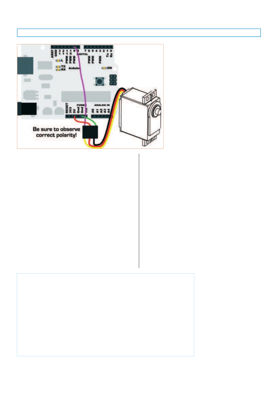
The program in Code Example 1 swings the servo
motor one direction, then the other, briefly pausing in
between. You can use either an unmodified or modified
(continuous rotation) servo to see the code in action. Refer
to Figure 6 for a diagram on hooking up the servo. Use a
standard size (or smaller) analog servo; stay away from
larger or digital servos, as they may draw too much current
for the USB port on your computer to handle.
(In Code Example 1, text after the double slash //
characters means a comment. It’s for us humans. During
the compiling phase, comments are ignored, as they are
not part of the functionality of the sketch.)
The first line, #include <Servo.h>, tells the IDE that you
want to use the Servo library which is a standard part of
the Arduino IDE installation. (Other libraries may require a
separate download, but they are used in the same way.)
The name of the main Servo library file is Servo.h, so that is
what’s provided here.
The line Servo myServo creates, or “instantiates,” a
servo object; the functionality of this object is defined in
the Servo.h library and its accompanying Servo.cpp
programming code file.
Servo
is actually a name of a class; that’s
how Arduino uses its libraries. With a class, you
can create multiple instances (copies) of an
object, without having to duplicate lots of
code. In the case of servos, for instance, you
could create two objects: one for each physical
servo on your robot. That’s what we did in the
code example in the December ‘10 issue of
SERVO Magazine
. Feel free to have a look at
that example sketch.
Again, note that Servo is the name of the
class to use, and myServo is the name I’ve
given to the object just created. You can use
most any name for an object, as long as it
conforms to the requirements of the C
language. I won’t go into any detail here about
these requirements, as you can find plenty of
guides and examples on the Web. The most
important ones are: the name can’t have any
spaces, it may include only numbers, letters, and the _
(underscore) character; and it can’t be the same as any
programming statements already defined for the Arduino.
The line int delay = 1000 creates a data variable named
delay
. Variables are used to hold information for use
throughout the sketch. The int tells the Arduino compiler
that you wish to create an integer type variable which can
store any whole number from -32,768 to 32,767. Other
data types supported in the Arduino include unsigned int
which holds values from 0 to 65,536, byte (holds 0 to 255),
and Boolean (holds true or false).
The setup() function contains one statement,
myServo.attach(9)
. Here’s what it all means:
• myServo
is the name of the servo object that was
defined earlier.
• attach
is a method that you can use with the myServo
object. Methods are actions that you use to control the
behavior of objects. In this case, attach tells the Arduino
that you have physically connected the servo to digital pin
D9 and you want to activate it. A period separates the
object name and method —
myServo.attach
.
Notice the ; (semi-colon) at
the end of the statement. It’s a
statement terminator. This tells
the compiler that the
statement is complete and to
go on to the next line. The
semi-colon is standard C
programming syntax, but if
you’re used to a language like
Basic — which simply uses hard
returns to denote when a
statement ends — the semi-
colon business is bound to
FIGURE 6.
Connection
diagram for testing
servo functionality with
the Arduino.
64
SERVO 01.2011
#include <Servo.h>
// Use the Servo library, included with
// the Arduino IDE (version 0017 or later)
Servo myServo;
// Create a Servo object to control the servo
int delayTime = 2000;
// Delay period, in milliseconds
void setup()
{
myServo.attach(9);
// Servo is connected to pin D9
}
void loop()
{
myServo.write(0);
// Rotate servo to position 0
delay(delayTime);
// Wait delay
myServo.write(180);
// Rotate servo to position 180
delay(delayTime);
// Wait again
}
CODE EXAMPLE 1
worldmags
cause some initial troubles. You’ll get used to it
though, and before long you’ll be adding semi-
colons to everything you write — even grocery
lists!
The loop() function contains the part of
the sketch that is repeated over and over again
until you download a new program or remove
power from the Arduino. The function contains
four lines.
• myServo.write(0) is another method using the
myServo object. The write method instructs the
servo to move all the way in one direction.
When using a modified servo, this statement
causes the motor to continually rotate in one
direction.
• delay(delayTime) tells the Arduino to wait the period
specified earlier in the delayTime variable which is 2,000
milliseconds (two seconds).
• The two statements are repeated again, this time with
myServo.write(180) to make the servo go the other
direction.
Before continuing, I want to mention an important
note about capitalization of variables, objects, and
statement names. Like all languages based on C, these
names are case sensitive, meaning myServo is distinctly
different from myservo, MYSERVO, and other variations. If
you try to use
myservo.attach(9);
(note the lower-case s) when you’ve defined the object as
myServo, the Arduino IDE will report an error — “myservo
not declared in this scope.” If you get this error, double-
check your capitals.
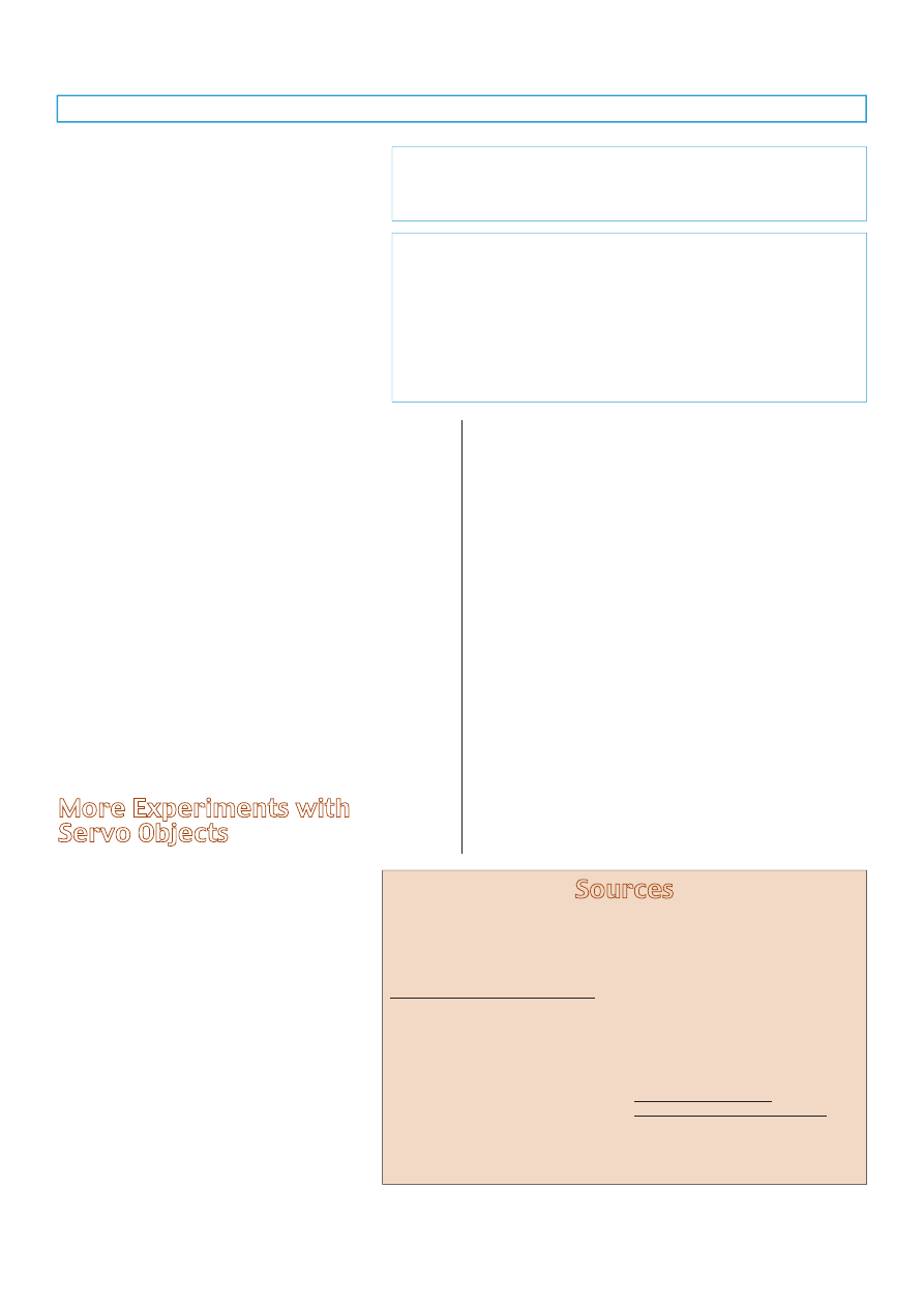
More Experiments with
Servo Objects
The Servo class provides a number of
methods that can be used on its objects. I
recommend you check out the documentation
for the Servo library on the arduino.cc website,
but here are the principle ones you should
know about:
• attach
connects a servo object to a specific
pin of the Arduino. You can use any pin.
• detach
removes the servo object, effectively
disabling the servo and removing its power.
• write
specifies where to position the servo.
The method accepts several forms of values.
A value of 0 to 180 denotes degrees; this
positions the shaft of the motor to a
corresponding angle. (When used with
modified servos, 0 and 180 make the motor
turn one direction or the other; 90 makes the
motor stop.) Values from 544 to 2400 are treated as
microseconds and position the servo by generating pulses
of the specified duration. Typical servo specs are 1,000 to
2,000 microseconds for a standard 60 degree arc.
• writeMicroseconds specifically indicates you wish to use
microseconds to control the servo position.
• read
returns the last specified position of the servo in
degrees.
One technique to try is writing a position to the servo
before calling the attach method — attaching the servo is
what gives it power. When you create a new Servo object,
its position is automatically given a default of 0. By setting
a position first, then attaching the servo, you can have it
start at a position other than 0 degrees. See Code
Example 2.
There’s also no absolute requirement that you use the
attach method in the setup() function. You can place it in
the loop() function and use the detach method to remove
power to the servo. Code Example 3 demonstrates
sweeping the servo right and left, while stopping it (actually
turning it off) for four seconds in between. The action is a
bit easier to see when using a servo modified for
continuous rotation.
SERVO 01.2011
65
Arduino
www.arduino.cc
Prefabricated ArdBot body pieces
with all construction hardware.
Partial list of Arduino resellers:
Budget Robotics
www.budgetrobotics.com
AdaFruit
www.adafruit.com
HVW Tech
www.hvwtech.com
Jameco
www.jameco.com
Pololu
www.pololu.com
Robotshop
www.robotshop.com
Solarbotics
www.solarbotics.com
Sparkfun
www.sparkfun.com
Arduino circuits and
sketches submitted by users:
Fritzing
www.fritzing.com
Sources
void setup()
{
myServo.write(180); // Start at 180 degrees instead of 0
myServo.attach(9);
}
CODE EXAMPLE 2
void loop()
{
myServo.attach(9);
// Attach and apply power
myServo.write(0);
// Position servo
delay(delayTime);
// Allow transit time
myServo.detach();
// Detach and remove power
delay(4000);
// Wait 4 seconds
myServo.attach(9);
// Re-attach and apply power
myServo.write(180); // Move servo to other end
delay(delayTime);
// Allow transit time
myServo.detach();
// Detach again
}
CODE EXAMPLE 3
worldmags
worldmags
Detaching the servo will prevent it from buzzing, or if
using a servo modified for continuous rotation, will stop it
from slowly “creeping” when you set its position to 0
(stop). Since the servo is not being powered, it also saves
battery juice when your Arduino and servos are mounted
on a mobile robot.
(Okay, detaching to remove power probably won’t
work with digital servos. Detaching stops the Arduino from
sending pulses to the servo, which on analog models —
what most people use — effectively shuts them off. Digital
servos will continue to hold position even when its pulses
go missing. That’s what they are intended to do. So, the
above really applies to your typical, everyday, garden variety
analog servo.)
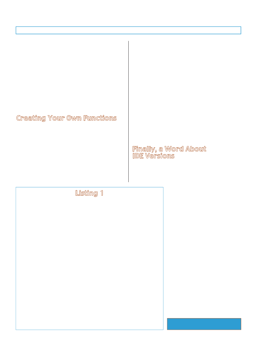
Creating Your Own Functions
The flexibility of any programming language —
Arduino included — comes in the ways you can develop
reusable code, such as creating user-defined functions. To
create a user-defined function, you give it a unique name
and place the code you want inside a pair of brace
characters, like so:
void forward() {
myServo.write(0);
delay(delayTime);
}
All user-defined functions must indicate the kind of
data they return (for use elsewhere in the sketch). If the
function doesn’t return any data, you use void instead. You
must also include parentheses to enclose any parameters
that may be provided for use in the function. In the case of
the forward user-defined function, there are no parameters,
but remember you need the ( and ) characters just the
same.
That defines the function; you only need to call it
from elsewhere in your sketch to use it. Just type its
name, followed by a semi-colon, to mark the end of the
statement line:
forward();
See Listing 1 for a full demonstration of an Arduino
sketch that runs a servo forward and backward, then briefly
stops it using the detach method. Recall the effect of the
sketch is most easily seen when using a servo modified for
continuous rotation, as is the case for a robot like the
ArdBot that uses continuous rotation servos to propel it
across the floor.
Finally, a Word About
IDE Versions
The Arduino IDE and the standard programming
statements and libraries often undergo changes with each
new version. The Servo library as detailed here was
introduced in version 0017 of the Arduino IDE. As of this
writing, we’re up to version 0021.
If you already have an installed
version of the IDE and it’s old, you’ll
want to fetch the newest version. You
can keep multiple versions of the
Arduino IDE on your computer, and
even switch between them as needed —
though that should seldom be required.
The ArdBot project requires version
0017 or later. I’ve tested everything on
version 0019, plus the latest build
(0021) just to make sure everything
still works as it should. The Arduino
IDE is set to always check for the latest
updates. If you open the IDE and it
tells you a new update is ready,
download and install it, and be sure to
take a look at the readme file for the
latest changes.
In future installments, you’ll be
integrating what you’ve learned here
with the ArdBot robot, including writing
your own customized servo motor
control functions, plus adding sensors to
your ArdBot to make it detect and avoid
obstacles, and more.
SV
66
SERVO 01.2011
Gordon McComb can be reached at
arduino@robotoid.com.
Listing 1
#include <Servo.h>
Servo myServo;
// Create Servo object
int delayTime = 2000;
// Standard delay period (2 secs)
const int servoPin = 9;
// Use pin D9 for the servo
void setup() {
// Empty setup
}
void loop() {
// Repeat these steps
forward();
// Call forward, reverse, servoStop
reverse();
// user-defined functions
servoStop();
delay(3000);
}
void forward() {
// Attach servo, go forward
myServo.attach(servoPin); // for delay period
myServo.write(0);
delay(delayTime);
myServo.detach();
// Detatch servo when done
}
void reverse() {
// Do same for other direction
myServo.attach(servoPin);
myServo.write(180);
delay(delayTime);
myServo.detach();
}
void servoStop() {
// Stop the servo by detaching
myServo.detach();
}
worldmags
worldmags
Wyszukiwarka
Podobne podstrony:
Making Robots With The Arduino part 1
Making Robots With The Arduino part 5
Making Robots With The Arduino part 2
Making Robots With The Arduino part 1
Making Robots With The Arduino part 5
PENGUIN READERS Level 4 Gone with the wind Part 1 (Answers)
Making Contact with the Self Injurious Adolescent BPD, Gestalt Therapy and Dialectical Behavioral T
PENGUIN READERS Level 4 Gone with the wind Part 1 (Factsheets)
PENGUIN READERS Level 4 Gone with the wind Part 1 (Worksheets)
War with the Robots Harry Harrison
Harrison, Harry War with the Robots
Harrison, Harry War with the Robots
5 2 1 8 Lab Observing ARP with the Windows CLI, IOS CLI, and Wireshark
anyway on with the show
9 Ask?out the underlined part of the sentence
więcej podobnych podstron