I
n the last installment, we introduced the ArdBot and
its central Arduino brain. This month, we’ll continue
the discussion with full construction plans for the
ArdBot. I built the reference design using 1/4”
expanded PVC plastic, but you can use wood, acrylic, foam
board, picture frame mat, or most anything else that is rigid
enough for the components.
ArdBot Basic Design
The ArdBot uses two “decks” for mounting a pair of
servo motors, batteries, microcontroller, small prototyping
board, and other components you’d like to experiment
with. The bottom deck is basically a 7” diameter circle with
cutouts for the wheels. The top deck is the same 7”
diameter circle with the side lobes cut off.
The decks are separated by a set of four 1-3/4” long
standoffs. The actual length of the standoffs is not really
important. You can make them shorter or longer — 1-1/2”
is the practical minimum and 3” the maximum.
While it’s a bit more challenging to cut circles to make
a robot base, it’s the best overall shape for navigating tight
places like mazes or the corner of a living room. The
concept of the ArdBot is flexibility, however. There’s no
reason your version must be circular. You can make a
square bot if you’d like, or cut off the corners of the square
to make an octagon.
If you don’t want to construct the mechanical pieces of
the ArdBot at all, you can get them precut with all the
hardware; see the Sources box. ArdBot is designed for
expandability. If the twin decks do not provide enough
space for all your experiments, you can add more decks. I
don’t recommend any more than three decks total, as any
more may pose a weight problem for the drive system.
The brain of the ArdBot is an Arduino Uno — the latest
of the all-in-one core designs of the Arduino. If you already
own an earlier version of the board — a Diecimila or
Duemilanove — those will work, too. The only requirement
is that you have version 0017 or later of the Arduino
programming environment. The ArdBot project was created
and tested using version 0019 — the latest as of this
writing. Complementing the Arduino microcontroller board
is a mini solderless breadboard. It has 170 tie points —
Making Robots
With The
The ArdBot is a low-cost, 7” diameter servo-driven robot base, ready for
expansion. It’s called ArdBot because it’s based on the popular and
inexpensive Arduino microcontroller board. The ArdBot costs under $80 to
build; even less if you already have some of the components, like the
breadboard, jumper wires, and battery holder.
A
rduino
Part 2
By Gordon McComb
In preparing Part 1 of this series, I made a last-minute
change to include the new Ardunio board that's just been
released. Only I got the name wrong — in several places in
the article, I referred to the new board as the Duo. The
correct name for the board is the Uno.
52
SERVO 12.2010
worldmags
worldmags
worldmags
enough for the basic experiments we’ll be doing in this
series of articles. Don’t let the small size of the breadboard
limit you. The ArdBot is large enough for bigger
breadboards, even multiple boards, should you need them.
You might want to start with the mini breadboard, then as
you use the ArdBot for further experiments you can add
more prototyping space.
About the Servo Drive
The ArdBot uses differential steering where the base is
propelled by two motors and wheels on opposite sides. To
keep costs down and minimize construction complexity, the
robot uses a pair of skids placed in the front and rear to
provide balance. With this arrangement, the ArdBot is able
to move forward and back, turn left and right, and spin in
place. The skids are smooth and polished metal, so they
present little drag on whatever surface the robot is rolling
over. Even so, the ArdBot is best suited for travel on hard
surfaces or carpet with a short nap.
The two drive motors run off their own battery supply
which is a set of four AA rechargeable or non-rechargeable
cells. The motors are standard size radio control airplane
servos that have been modified for continuous rotation.
The ArdBot reference design uses servos that come
from the factory already modified so you don’t have to
hack them. I used a pair of GWS S-35 servos, but there are
others available (see Sources) for under $15 each. I won’t
provide instructions here on how to modify a servo for
continuous rotation. That subject has been tackled in past
issues of SERVO and Nuts & Volts, so I’ll leave it at that.
Making the ArdBot Base
The ArdBot is constructed with four body pieces held
together with hardware fasteners. Table 1 provides a full
list of mechanical parts. Tables 2 through 5 specify the
other components to complete the ArdBot.
All body pieces assume 1/4” thick material. For your
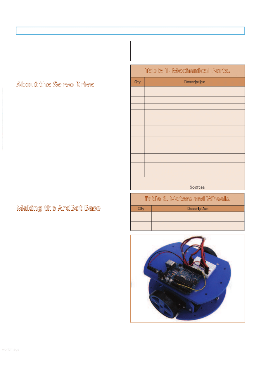
reference, Figure 1 shows a completed ArdBot, ready to be
programmed and played with. The body pieces include:
• Bottom deck
measuring 7” diameter with cutouts for
the wheels (see Figure 2). The deck includes a
number of holes, of which only six are required. Any
other holes are up to you. I’ve included several
additional holes at the front and back of the deck for
mounting bumper switches and other sensors. The
wheel cutouts measure 2-5/8” x 7-5/8”; sized for
commonly available 2-1/2” or 2-5/8” diameter robotic
wheels for R/C servo motors.
• Top deck
measuring 7” x 5” (see Figure 3). Only four
of its holes are critical; these mate with matching
holes in the bottom deck using a set of four
standoffs. A 1/2” diameter hole in the center (or
thereabouts) provides a throughway for wires from
the bottom deck. The other holes as shown are
optional, and are for attaching sensors and other
accessories.
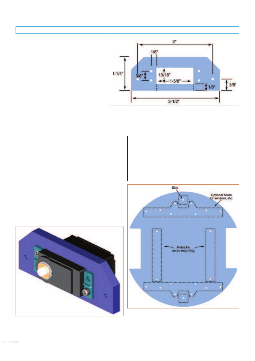
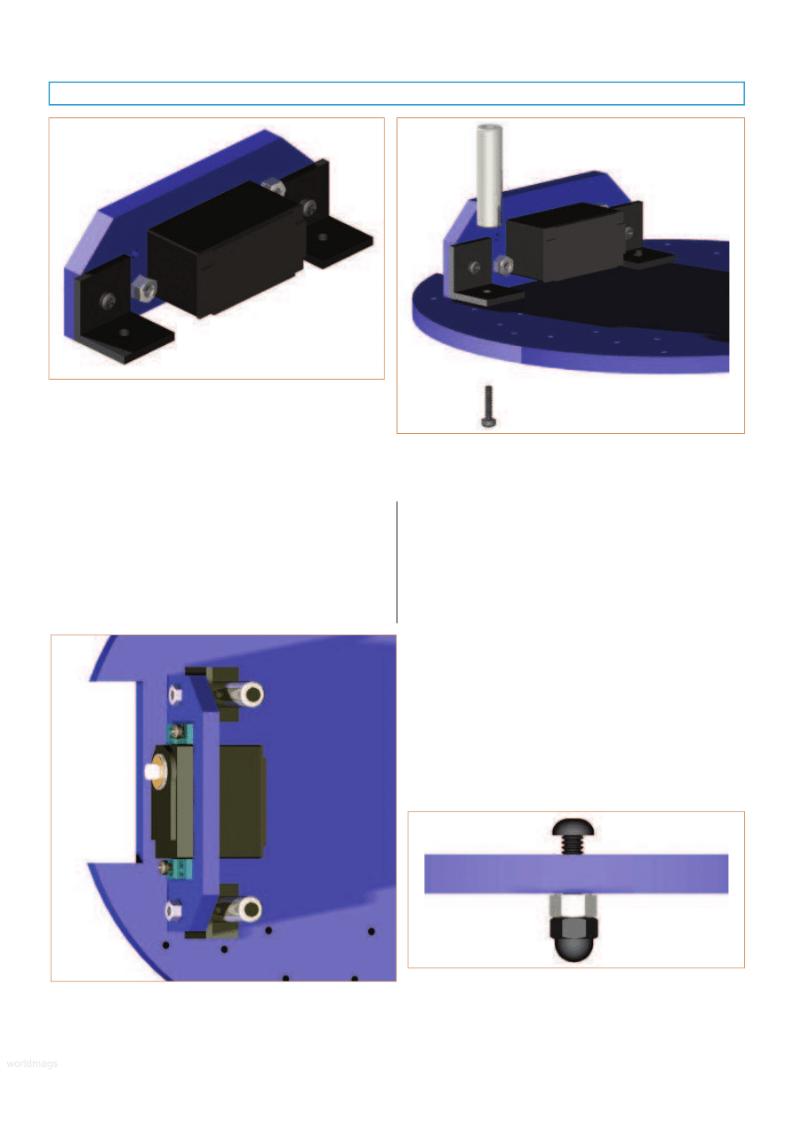
• Pair of servo mounts
(see Figure 4) for attaching the
servos to the bottom deck. You can make these
www.servomagazine.com/index.php?/magazine/article/december2010_McComb
Table 1. Mechanical Parts.
Qty
Description
1
7” diameter bottom deck with wheel well cutouts
for the drive wheels.
1
7” × 5” top deck.
2
Servo mounts.
4
90° plastic L brackets for attaching the servo
mounts to the bottom deck. These brackets
measure 3/4” × 3/4” with hole centers at 3/8”, and
are made to work with the two servo mounts.
16
4-40 x 1/2” machine screws and nuts for attaching
the servos and servo mounts to the bottom deck.
4
Deck risers consisting of: (4) 1-3/4” aluminum
(or plastic) risers with 4-40 threads; (4) 4-40 × 1/2”
pan head machine screws; and (4) 4-40 × 1/2”
flat head machine screws.
2
Skids consisting of: (2) 8-32 × 3/4” machine screws;
(2) 8-32 hex nuts; and (2) 8-32 acorn (cap) nuts.
3
Sets of mounting hardware for Arduino Uno,
consisting of (3) 4-40 × 1/2” machine screws;
(3) 4-40 nuts; and (3) plastic washers.
* For your convenience, all mechanical pieces — including
precut decks and servo mounts — at are available through
Budget Robotics. See the Sources box for details.
Table 2. Motors and Wheels.
Qty
Description
2
Standard size R/C servo motors, modified
for continuous rotation.
2
2-1/2” or 2-5/8 diameter wheels with hubs
to attach to the servo motors.
FIGURE 1.
The completed ArdBot with Arduino microcontroller
board, solderless breadboard, servos, wheels, and all body parts.
SERVO 12.2010
53
worldmags
worldmags
worldmags
yourself or, if you choose, purchase them separately.
If you make the mounts, be aware that sizing is
critical. The two holes on either side of the mount
must be spaced 3” apart to accommodate the same
hole spacing in the bottom deck.
The base parts may be cut from stock measuring 12”
x 12” which is a common size for expanded PVC or other
plastic purchased through mail order. A motorized scroll
saw is the perfect tool for cutting out the ArdBot base
components, but if you don’t have one handy, a coping
saw also works. Use a wood blade; it’ll work whether
you’re making the base with aircraft-grade plywood
(available at the hobby store), PVC, or other plastic.
If using foam board or picture mat, you can cut the
pieces using a sharp hobby knife or mat cutter. The usual
safety precautions apply. A circle cutting jig makes perfect
circles when using these materials. If you don’t own a
circular jig yourself, see if the local picture frame store will
make the cuts for you. When using picture mat material,
cut two of everything, and double-up the pieces for extra
stiffness. Except for the large center hole in the top deck,
all holes are drilled with a 9/64” bit.
Assembling the ArdBot
With the body pieces constructed (or purchased) and
all other parts in hand, you’re ready to build your ArdBot.
Here’s how.
Step 0
Before assembly, you may want to use 150 grit
sandpaper to smooth the edges of the base parts. Orient
the bottom deck so that the holes are aligned as shown in
Figure 5. Note that the holes for each servo are not
symmetrically placed on the deck. This is to accommodate
FIGURE 2.
Layout pattern for cutting and drilling the bottom
deck of the ArdBot. The only truly critical dimensions are the
cutouts for the wheels and the placement of the two sets of holes
immediately beside the wheel cutouts. These holes are for the
servo mounts. See Figure 5 for a description of all holes.
Table 3. Electronic Parts.
Qty
Description
1
Arduino Uno (or compatible) microcontroller
board with USB programming cable.
1
Mini solderless breadboard; 170 tie points.
1
Set of solderless breadboard wire jumpers
(or make your own using 22 gauge solid
conductor wire).
1
AA x four battery holder, with female header
connector; see text.
1
Nine volt battery clip, with 2.1 mm polarized
barrel plug; see text.
1
Length of 12 (or more) breakaway 0.100” male
header pins, double-sided (long) pins; see text.
Table 4. Power.
Qty
Description
4
AA alkaline or nickel metal hybride
rechargable batteries.
1
Nine volt battery.
Table 5.
Optional (but nice to have) Parts.
Qty
Description
1
Nine volt metal or plastic battery holder.
1
Hook-and-loop (Velcro) strips for mounting
battery holders and solderless breadboard;
small pieces of double-sided foam tape.
FIGURE 3.
Layout
pattern for
cutting and
drilling the
top deck of
the ArdBot.
Critical holes
are the four
small ones
nearest the
center. These
must match
the four
servo
mounting
holes in the
bottom
deck.
54
SERVO 12.2010
worldmags
worldmags
worldmags
worldmags
the offset of the servo drive shaft. While there is
technically no “front” or “rear” of the ArdBot, for
the purposes of assembly, the top of the
illustration in Figure 5 is the front and the
bottom is the rear.
Step 1
Insert a servo into a servo mount by sliding it
back-end first through the mount. The fit may be
tight, depending on the make and model of the
servo. (As necessary, enlarge the rectangle for the
servo using a file or coarse sandpaper.) Do not
force the servo into the mount or the mount may
be damaged.
Secure the servo to the mount with 4-40 x
1/2” screws and hex nuts (Figure 6). You can use
four screws for each servo, or only two. When
using two screws position them on opposite
corners of the servo mounting flange, as shown.
Repeat for the opposite servo and mount. Be sure to
construct the second servo and mount in a mirror image to
the first! Refer to Figure 9 in Step 3 to see how the motors
should be inserted into the mounts. For reference, also see
Figure 12 for an aerial view of the ArdBot and its
completed bottom deck.
Step 2
Using 4-40 x 1/2” machine screws and nuts, attach
two plastic L brackets to each of the servo mounts (Figure
7). You’ll be make a “left” and a “right” mount assembly.
For the left mount assembly, the motor shaft should
face to the left and toward the “top” of the deck (as
referenced in Figure 5). Attach the L brackets to the right
side of the mount. For the right mount assembly, the motor
shaft should face to the right, also toward the top of the
deck. Attach the L brackets to the left side of the mount.
Insert the machine screws through the L bracket, then
through the servo mount. Secure on the other end with a
nut. Before tightening, be sure the bottom of the L bracket
is flush with the bottom edge of the servo mount.
Step 3
Attach the left mount assembly to the bottom deck
using two 4-40 x 1/2” screws and standoffs. The screws
should come up from the underside of the deck, through
FIGURE 4.
Layout pattern for cutting and drilling the servo mount. You’ll
need two of these. If cutting the inside rectangle proves difficult, you can
instead make the mounts by cutting through at the dotted line.
The mount will be a little more fragile, so handle it carefully.
Use all four screws to secure the servo in the mount, rather than just two.
FIGURE 5.
Only four holes are critical for the bottom deck: the two
sets marked Holes for servo mounting, and the front and rear Skid.
The rest are optional for sensors and other
accessories you may want to add later.
FIGURE 6.
Servo motor secured into one of the servo mounts.
You need two of these.
SERVO 12.2010
55
worldmags
worldmags
worldmags
the L bracket, and then into the standoff as shown in
Figure 8. When orienting the mount assembly, be sure that
the servo shaft is centered in the wheel well cutout. Align
the assembly so they are parallel with the wheel well
cutout, then tighten all the screws. Figure 9 shows how
the completed servo, mount, and standoffs should look.
Repeat the same procedure for the right mount assembly.
Step 4
Attach the front and rear skids as shown in Figure 10.
Each skid uses an 8-32” machine screw, hex nut, and acorn
(cap) nut.
1. Using a screwdriver, thread a machine screw into the
hole at the front and back of the deck (refer to
Figure 5 for the location of these holes). The screw
is inserted from the top of the deck (the side with
the servos). The holes for the skids are undersized
for 8-32 machine screws. When using a soft material
like wood or PVC plastic, the fastener will tap the
hole as you screw it in. Continue threading the screw
into the hole until the head is about 1/4” from the
deck, as indicated in the picture.
2. Put the hex nut onto the screw, followed by the
acorn nut. Tighten the acorn nut against the hex
nut.
Repeat these steps for the other skid. You may adjust
the height of the skid by loosening or tightening the
machine screw in the hole. If you need greater height
adjustment or the hole for the skid is too large to self-tap,
FIGURE 8.
Secure the servo mounts to the bottom deck using
machine screws and threaded standoffs.
The standoffs serve to separate the decks.
FIGURE 9.
Here’s how the completed servo mount should look
with standoffs in place.
FIGURE 10.
ArdBot uses static skids (made with 8-32 metal
fasteners) for front and back balance. You can adjust the height
of each skid to compensate for the diameter of wheels you use.
FIGURE 7.
Attach two L brackets to the servo mount. The L
brackets should be flush with the bottom of the servo mount.
56
SERVO 12.2010
worldmags
worldmags
worldmags

merely use a longer machine screw and tighten into place
using nuts on both the top and bottom of the deck, as
shown in Figure 11.
Step 5
Attach the wheels to the servos. Each wheel is secured
with a small self-tapping screw that is supplied with the
servo. Note that the servo shaft is splined; this spline
matches the wheel hub. Be sure to press the wheel onto
the shaft firmly while tightening the screw. Do not over-
tighten the wheel mounting screw, but be sure the wheel is
on snugly. Figure 12 shows the completed bottom deck of
the ArdBot, with motors, mounts, and wheels attached.
(I’ve bound the wire leads for the servos using cable ties to
keep things neat. You can do the same if you wish.)
Step 6
Secure the side of the nine volt battery holder against
the side of the AA battery holder using a small piece of
double-sided foam tape or hook-and-loop (Velcro). Next,
secure the AA battery holder to the approximate center of
the bottom deck using a square or two of hook-and-loop to
keep it in place. Note the electrical connections for both the
nine volt battery and the AA battery holder:
• The nine volt battery uses the traditional two-prong
battery clip, terminated on the other end with a 2.1
mm barrel plug. This plug inserts into the power jack
of the Arduino. You can make this power lead
yourself by soldering a barrel plug onto a standard
two-prong battery clip, or purchase one ready-made
(see the Sources box). When constructing your own,
be absolutely sure the + (positive) connection is the
center of the plug; the – (negative) connection is the
outside of the barrel.
• The AA battery holder uses a female 0.100” pin
header connector. You can use a connector with two
or more pins; the additional pins can be used to help
assure proper polarity. With just two pins, you must
be VERY careful to never (and I mean NEVER, EVER!)
reverse the polarity of the connector. If you do, your
servos will be instantaneously and permanently
damaged. By using (for example) a four pin
connector, you can block up one of the unused
terminals. This helps prevent you from reversing the
connector when you plug it in. (Of course, still be
careful, no matter what system you use!) Insert fresh
batteries into the holders and attach the clip to the
nine volt battery. The holders with batteries are
shown in Figure 13.
Step 7
Find a favored spot on the top deck for your Arduino,
and mark three holes for mounting the board. Be sure not
FIGURE 12.
The completed bottom deck of the ArdBot. Note the
orientation of the servos in the mounts.
FIGURE 11.
If you need additional height control for the skids
or the hole for the skid cannot be threaded, use a longer 8-32
screw with hex nuts above and below the deck.
FIGURE 13.
The bottom deck is large enough for several battery
packs, and they can be neatly placed in the center. The reference
design uses a nine volt battery to power the Arduino, and a
holder with four AA cells to power the servo motors.
SERVO 12.2010
57
worldmags
worldmags
worldmags

to cover up any of the four holes used for securing the top
deck in place. Otherwise, you’ll have to remove the Arduino
in order to take off the top deck
Drill the three holes using a 9/64” bit. Secure the
Arduino board to the top deck using 4-40 machine screws,
nuts, and plastic washers. The washers go between the
heads of the screws and the board, and minimize the
possibility of a short circuit.
Mount the mini solderless breadboard so that it’s close
to the Arduino, but doesn’t block the 1/2” wiring access
hole in the top deck. Though most mini breadboards come
with double-sided self-adhesive tape, I recommend that you
don’t use the tape. Instead, mount the board using a
square or two of hook-and-loop. This allows you to easily
remove the board when you need to.
Step 8
To complete the ArdBot, secure the top deck to the
standoffs using 4-40 x 1/2” flat head screws. Assuming you
are using a soft material (wood, PVC plastic, foam board,
etc.), the heads of the screws should countersink by
themselves as you tighten them and lay flush against the
deck. Thread the battery and servo leads through the center
hole of the top deck. To keep down cost and complexity,
there are no power switches for the batteries, so leave the
battery leads unattached until you’re ready to program and
use the ArdBot. (When you’re done playing, be sure to
unplug the batteries to keep them from draining.)
Two-Servo Wiring Plan
The Arduino lacks direct connections for attaching the
servo motors. Instead, the mini breadboard provides
prototyping space for connecting up both servos, as well as
the AA battery holder that powers the servos. Refer to
Figure 14 (schematic) and Figure 15 (pictorial) for wiring
the solderless breadboard. Using a strip of 0.100” double-
sided (long) male header pins, break off two sets of three
pins, and one set of pins for the AA battery connection.
Note that you want the version of male header pins
that are “double-sided” — they’re long on both sides. If you
use the standard header pins, the length of pins on one
side is shorter. These don’t make good contact when used
with solderless breadboard designs. See the Sources box
for a couple of mail order companies offering double-sided
long header pins. In a pinch, you can use right-angle header
pins instead and straighten them out so that all the pins are
flat. The reference design uses a AA battery holder with a
four-pin female connector. The + and – leads are on the
two outside positions of the connector. I’ve broken off the
pin right next to the + connection of the male header, then
used a short piece of solid conductor hookup wire to fill in
its corresponding hole in the connector. This prevents the
connector from being reversed when plugged in.
When wiring the solderless breadboard, be especially
careful not to mix positive and negative leads to the servo.
Reversing the power leads to a servo will permanently
Listing 1
/*
ArdBot ServoTest
Tests servos of robot by moving them in
different directions
Requires Arduino IDE version 0017 or later
(0019 or later preferred)
*/
#include <Servo.h>
Servo servoLeft;
// Define left servo
Servo servoRight;
// Define right
servo
void setup()
{
servoLeft.attach(10);
// Set left servo to
// digital pin 10
servoRight.attach(9);
// Set right servo
to
// digital pin 9
}
void loop()
// Loop through
// motion tests
{
forward();
// Example: move
// forward
delay(2000);
// Wait 2000
// milliseconds
// (2 seconds)
reverse();
delay(2000);
turnRight();
delay(2000);
turnLeft();
delay(2000);
stopRobot();
delay(2000);
}
// Motion routines for forward, reverse, turns,
// and stop
void forward()
{
servoLeft.write(0);
servoRight.write(180);
}
void reverse()
{
servoLeft.write(180);
servoRight.write(0);
}
void turnRight()
{
servoLeft.write(180);
servoRight.write(180);
}
void turnLeft()
{
servoLeft.write(0);
servoRight.write(0);
}
void stopRobot()
{
servoLeft.write(90);
servoRight.write(90);
}
58
SERVO 12.2010
worldmags
worldmags
worldmags
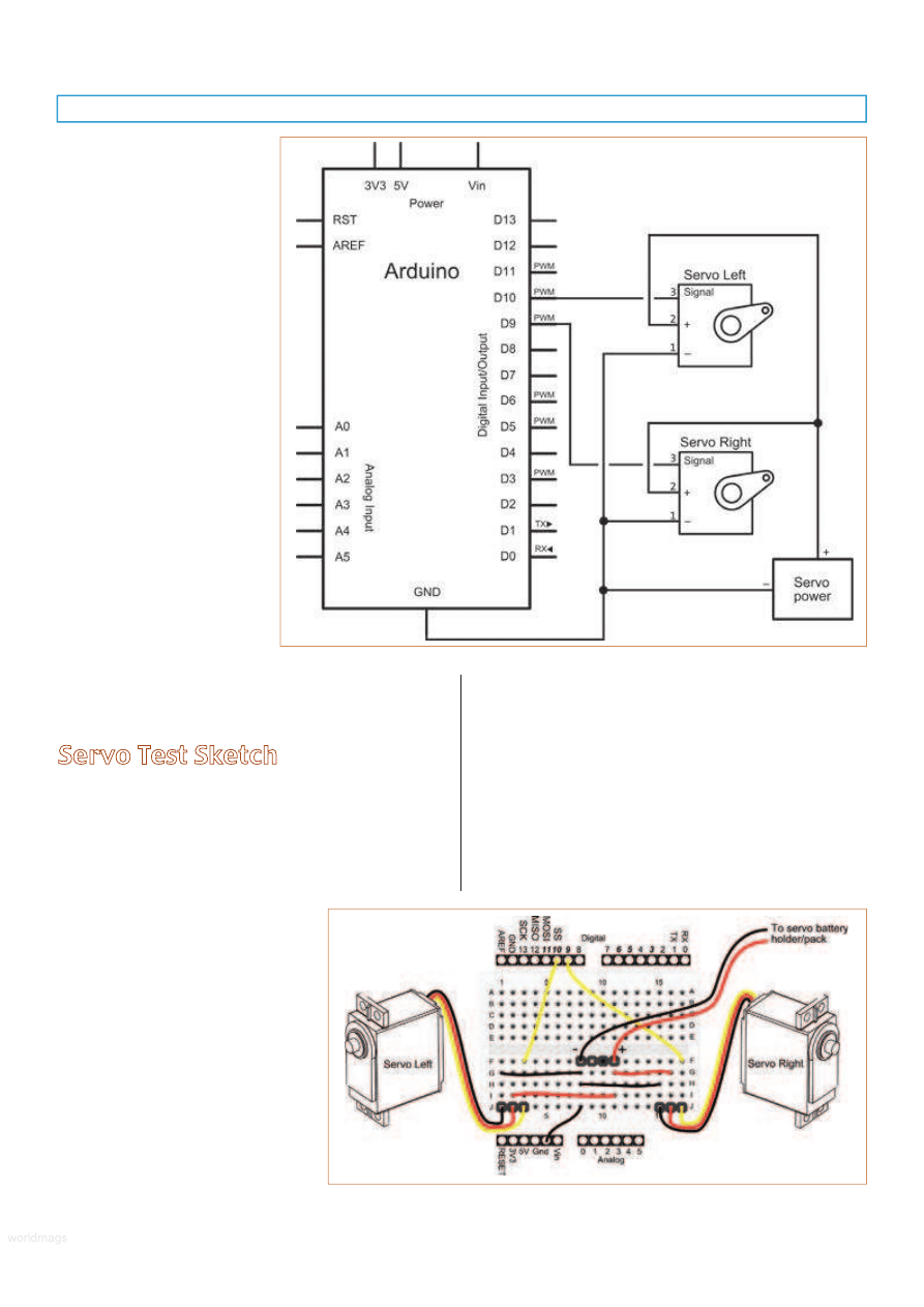
damage it. Here’s an important
note
: The ArdBot uses separate
battery supplies for the Arduino
and the two servos. In order for
everything to function properly,
the ground connections for the
Arduino and the servo battery
supply must be connected
together. This is shown in both
the schematic and pictorial
circuit views.
Make sure to also properly
orient the connectors for the
servos when you plug them
into the board. Servo power
leads are color-coded, but the
colors aren’t universal.
• Ground (–) is typically
black or brown.
• Power (+) is most often
red, and with modern
servos is always in the
middle.
• Signal is white, yellow, or
sometimes orange (but
take care — on some
servos the power wire is
orange!).
When in doubt, check the spec sheet that comes with
your servos. Don’t guess!
Servo Test Sketch
With the ArdBot constructed and the breadboard
wired, you’re ready to test the robot and put it through its
paces. Refer to Listing 1 for a quick servo test sketch.
Start the Arduino IDE, connect a USB cable between
your computer and the Arduino (as noted on the Getting
Started pages of the Arduino website), and type the
program as shown. When done, Verify
(compile) the sketch and look for any
syntax errors. If there are none,
download the sketch to your Arduino.
Once downloaded, put a small
book under your ArdBot to lift its
wheels off the ground. Disconnect the
USB cable, and — in this order — plug
the AA battery connector into the
breadboard, then plug in the nine volt
power to the Arduino power jack. (If you are using an
Arduino Diecimila, be sure to switch over the power
selection jumper from USB to EXTernal.) If everything is
connected properly, the servo motors should go through a
test pattern.
Assuming the motors are working as they should,
depress the Reset switch on the Arduino board and place
the ArdBot on the ground. Release the switch and the
robot should perform its self-test maneuvers. If the motors
aren’t moving, double-check your wiring, making sure the
servo connectors are properly oriented. They won’t work if
the connectors are reversed on the breadboard.
FIGURE 15.
Pictorial view of how to
connect the Arduino to the two servo
motors. Note that the Arduino ground
connection is shared with the power for
the servos. This is very important.
FIGURE 14.
The wiring schematic for the
Arduino with two servos and separate power
supply for the motors.
SERVO 11.2010
59
worldmags
worldmags
Closer Look at the Test Sketch
Before closing out this month’s installment of the
ArdBot, let’s quickly review how the test sketch works. First
off is an include statement to the Servo.h library header file
which is provided with the Arduino IDE installation. This file
and its corresponding C language program, provide all the
actual coding to make the servos function.
Next comes two statements that create, or instantiate,
two Servo objects for use in the remainder of the sketch.
Each object represents a physical servo attached to the
Arduino. Methods of these objects include things like
specifying which digital pin is used to connect from the
Arduino to the servo, and the position of the servo. Note
I’ve given the two Servo objects descriptive names:
servoLeft and servoRight. It’s easier to keep track of things
this way.
In the setup function, the servoLeft and servoRight
objects are “wired” to their respective pins on the Arduino;
in this case, pin 10 for servoLeft and pin 9 for servoRight.
Now comes the main body of the program, provided in
the loop function. It contains a series of user-defined
functions for forward, backward, and so on, plus a delay of
2,000 milliseconds (two seconds) between each function.
You can see that the robot repeats the same demonstration
steps over and over:
• Goes forward for two seconds.
• Reverses for two seconds.
• Turns right for two seconds.
• Turns left for two seconds.
• Stops for two seconds.
Finally, each user-defined function specifies the specific
motion to apply to the servos.
With the Servo object, servos are
commanded to move one
direction or another by (among
other ways) specifying an angle
between 0 and 180. The servo
then moves to that angle in
response.
When using servos that have
been modified for continuous
rotation, 0 makes the servo rotate
one direction; 180 makes the
servo rotate in the opposite
direction; and 90 makes it stop.
Pretty easy, isn’t it?!
In our next installment, we’ll
look at servo programming in
depth, as well as connecting some
sensors to the ArdBot for reactive
control, getting feedback from the
robot, and more!
SV
Please note! The list of sources is not exhaustive, and is
merely designed to get you started in the right direction.
There are other companies who sell these items, and not all
sources are listed. Common parts like battery holders and
breadboard jumper wires are not included here, as they are
readily available at RadioShack and hundreds of online
electronics supply stores.
Check out
www.fritzing.com
for a user-to-user Arduino
project community, including an Arduino development library
that allows you to create virtual breadboard designs of your
projects. You may then turn your projects into schematics and
even etchable circuit boards. We’ve used Fritzing to prepare
some of the illustrations for this series of articles.
Sources
Gordon McComb can be reached
at rduino@robotoid.com.
Arduino
www.arduino.cc
Prefabricated ArdBot body
pieces with all construction
hardware.
Budget Robotics
www.budgetrobotics.com
AdaFruit
www.adafruit.com
HVW Tech
www.hvwtech.com
Jameco
www.jameco.com
Parallax
www.parallax.com
Pololu
www.pololu.com
Robotshop
www.robotshop.com
Solarbotics
www.solarbotics.com
SparkFun
www.sparkfun.com
60
SERVO 12.2010
This is a selected list of North American
sources for the main components for the
ArdBot.
Arduino Duo or Duemilanove
Source
Item or SKU
Adafruit
50
HVW Tech
28920 (Freeduino SB)
Jameco
2121105
RobotShop
RB-Ard-03
Pololu
1616
SparkFun
DEV-09950
Solderless Breadboard; 170 tie-points
Source
Item or SKU
Adafruit
65
HVW Tech
21380
Jameco
2109801
Parallax
700-00012
RobotShop
RB-Spa-139
Nine volt to 2.1 mm Barrel Plug
Cable
Source
Item or SKU
Adafruit
80
SparkFun
PRT-09518
Continuous Rotation Servo
(Futaba spline)
Source
Item or SKU
Parallax
900-00008
Pololu
1248
RobotShop
RB-Gws-23
Solarbotics
36000
SparkFun
ROB-09347
2-1/2” or 2-5/8” Rubber Wheels
(Futaba spline)
Source
Item or SKU
Adafruit
167
HVW Tech/
Solarbotics
SW
Parallax
28109
Pololu
226
RobotShop
RB-Sbo-86
Double-sided (long) Male Header
Pins
Source
Item or SKU
Parallax
451-00303
Pololu
1065
Main Components Sources
worldmags
worldmags
worldmags
Wyszukiwarka
Podobne podstrony:
Making Robots With The Arduino part 1
Making Robots With The Arduino part 5
Making Robots With The Arduino part 3
Making Robots With The Arduino part 1
Making Robots With The Arduino part 5
PENGUIN READERS Level 4 Gone with the wind Part 1 (Answers)
Making Contact with the Self Injurious Adolescent BPD, Gestalt Therapy and Dialectical Behavioral T
PENGUIN READERS Level 4 Gone with the wind Part 1 (Factsheets)
PENGUIN READERS Level 4 Gone with the wind Part 1 (Worksheets)
War with the Robots Harry Harrison
Harrison, Harry War with the Robots
Harrison, Harry War with the Robots
5 2 1 8 Lab Observing ARP with the Windows CLI, IOS CLI, and Wireshark
anyway on with the show
9 Ask?out the underlined part of the sentence
więcej podobnych podstron