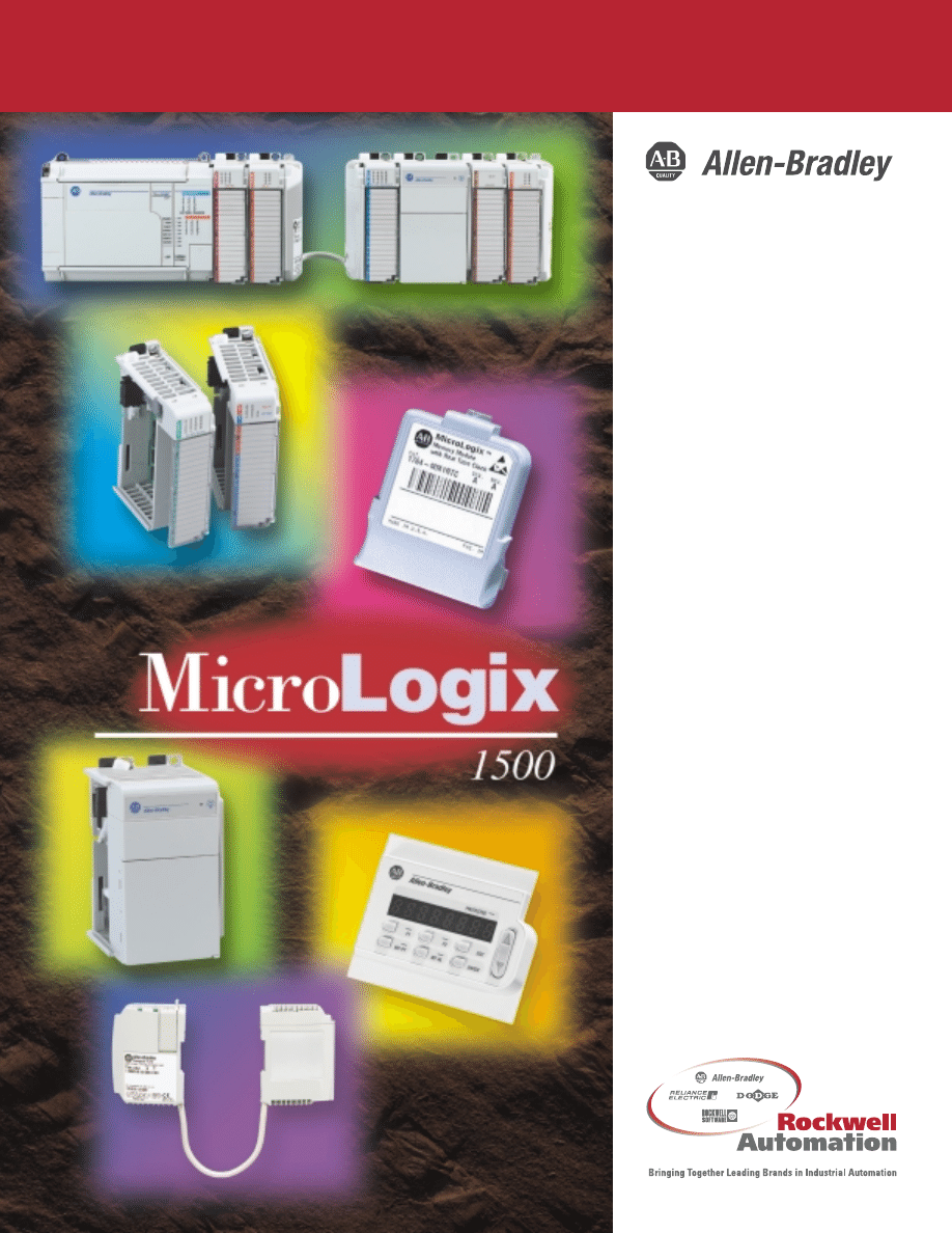
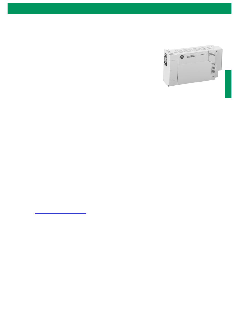
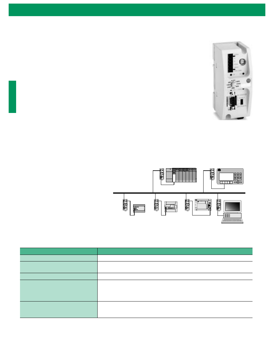
MicroLogix
™
1500
Programmable
Controller with
Compact
™
I/O
for Expansion
(Bulletins 1764 and 1769)
System Overview
There was a time when
a large controller was
needed for applications
requiring 100 or more
points of I/O. Not any
more. The MicroLogix 1500
is a more powerful and
expandable addition to
the MicroLogix family.
This dynamic packaged
controller can handle many
applications that used to require
larger, more expensive controllers.
World Class Features for
Many Applications
The MicroLogix 1500 has more robust features
than you might expect for a controller this size.
It supports up to 12K of onboard non-volatile
user memory to accommodate complex
application
programs, with
additional memory
for applications
that require data
logging.
Additionally, the
controller’s terminal blocks
are removable, “finger safe”
NEMA-style blocks. And because
it can be either DIN rail or panel
mounted, the MicroLogix 1500
takes up a fraction of the space of
larger controllers while reducing
overall application costs.
Communications are flexible for
the MicroLogix 1500, as well.
DH-485 and DeviceNet
™
compatibility are available via
add-on communication modules,
and DF1
™
Full-Duplex and Half-
Duplex Slave is perfect for SCADA
applications. Ethernet
®
and
MicroLogix 1500
Controllers:
Expanding Your Choices
for Greater Control
Take Control
Experience Complete Satisfaction
With Allen-Bradley Products
Since 1903, Rockwell Automation’s
Allen-Bradley has earned a worldwide
reputation as the most trusted brand name
in industrial automation. It’s a reputation
built on a very simple strategy: providing
customers with products of uncompromising
quality and reliability. The MicroLogix 1500
family of controllers demonstrates that
commitment to high standards of product
dependability, technological innovation,
and performance.
More importantly, because your absolute
satisfaction is important to us, we back our
products with the highest levels of customer
service and support in the industry. Your local
Rockwell Automation representative is your
source for expert sales and order support,
as well as:
• Product technical training
• Warranty support
• Service agreements
ControlNet
™
connectivity is available
via a wide range of bridge products.
Modbus RTU Slave capability
simplifies integration into SCADA/
RTU installations that use Modbus.
Finally, as with all MicroLogix
controllers, the MicroLogix 1500 is
programmed using the RSLogix
500
™
programming environment.
The instruction set is compatible
with all MicroLogix as well as
SLC controllers.
High-Speed Performance
Because many large manufacturing
applications occur at a fast pace,
the MicroLogix 1500 is built
for speed. For example, the
controller’s typical scan time
is less than 1 millisecond per
1K of user program. The
MicroLogix 1500 likewise
boasts two 20kHz high-
speed counters, each
with eight modes of
operation, and two
high-speed
outputs that
can be
configured
either as 20kHz Pulse Train Outputs (PTO) or as
Pulse Width Modulation (PWM) outputs. Finally,
you will find one selectable timed interrupt (STI)
and four event interrupts, making the
MicroLogix 1500 ideal for many
high-speed applications.
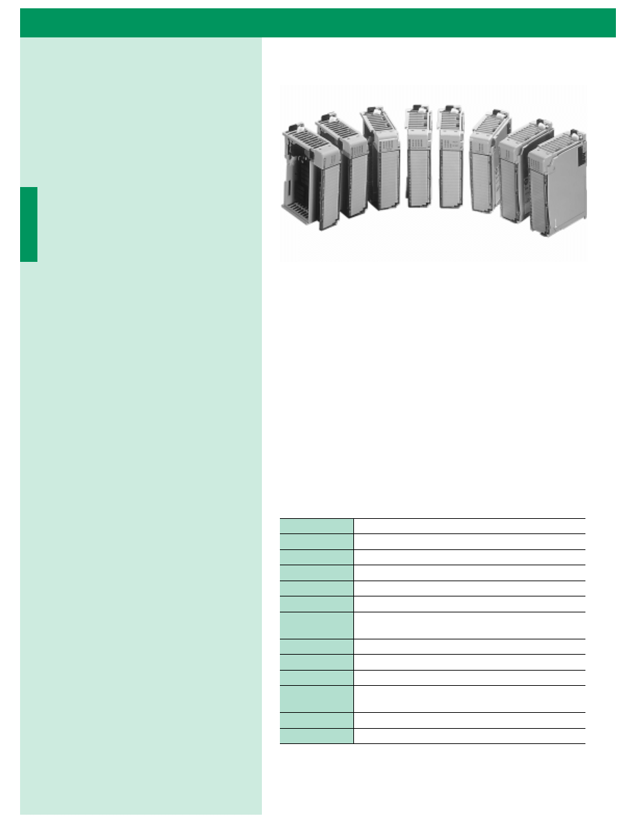
Application Flexibility
through Compact I/O
The magic behind the MicroLogix 1500
is its use of Compact I/O, a new
“PLC-style” I/O platform, for I/O
expansion. Compact I/O makes
use of the latest design technology
for superior performance and ease
of use while maintaining the MicroLogix 1500’s
small footprint.
Expandable to over 128 I/O points, Compact I/O
features an innovative rackless design,
reducing overall system cost. Its
modular, high-density configuration
reduces panel space requirements.
And because modules can be added
or replaced from the front of the unit,
installation and
maintenance time is
significantly reduced.
Compact I/O offers broad application coverage
via 24VDC sink/source and 120/240VAC I/O,
relay, and analog I/O.

MicroLogix 1500 Programmable Controller with Compact I/O for Expansion
4
Table of Contents
Refer to the MicroLogix Selector Guide
on the back cover of this publication for
assistance in selecting the correct
MicroLogix Programmable Controller for
your application.
Inside…
Page
MicroLogix 1500 System . . . . . . . . . . . . . . . . . . . . . . . . . . . 5
MicroLogix 1500 Specifications . . . . . . . . . . . . . . . . . . . . . 8
Expansion I/O Modules . . . . . . . . . . . . . . . . . . . . . . . . . . . . 10
Expansion I/O Module Specifications . . . . . . . . . . . . . . . . . 11
Expansion Power Supplies and Cables . . . . . . . . . . . . . . . . 13
Communication Choices . . . . . . . . . . . . . . . . . . . . . . . . . . . 15
Network Interface Devices . . . . . . . . . . . . . . . . . . . . . . . . . 18
High-Speed Functions . . . . . . . . . . . . . . . . . . . . . . . . . . . . . 21
Programming Software . . . . . . . . . . . . . . . . . . . . . . . . . . . . 22
Programming Instructions . . . . . . . . . . . . . . . . . . . . . . . . . . 24
Operator Interface Devices . . . . . . . . . . . . . . . . . . . . . . . . . 25
Accessories . . . . . . . . . . . . . . . . . . . . . . . . . . . . . . . . . . . . . 26
User Documentation . . . . . . . . . . . . . . . . . . . . . . . . . . . . . . 28
Dimensions . . . . . . . . . . . . . . . . . . . . . . . . . . . . . . . . . . . . . 29
MicroLogix 1500 Master Parts List . . . . . . . . . . . . . . . . . . . 31

5
MicroLogix 1500 Programmable Controller with Compact I/O for Expansion
Features
•
single or dual RS-232 communication ports
•
7K or 12K processors
•
32-bit signed integer math and built-in PID capabilities
provide you with process control power.
•
Embedded I/O provide enhanced high-speed inputs and
outputs.
•
Two analog trim potentiometers built into the controller. A
3/4 turn adjusts an integer between 0 and 250, allowing easy
adjustments to timer/counter presets, set points, conveyor
speed, valve adjustment, etc.
•
Two high-speed outputs that can be configured as 20 kHz
PTO (Pulse Train Outputs) or as PWM (Pulse Width
Modulated) outputs with two acceleration/deceleration
profiles. These high-speed outputs allow simple high-speed
applications such as packaging or printing to be solved using a
low-cost, small controller system as an inexpensive stepper or
servo motor controller.
•
Data file download protection, saves critical user data from
being overwritten during program transfers. Application/user
variables can be preserved when a new program is downloaded.
•
Programs written for MicroLogix 1000, MicroLogix 1200 or
SLC 500 controllers can be easily converted and scaled to work
with a MicroLogix 1500. That protects your software
investment when you need to scale your control system up or
down. And, it saves you time and money during development
and testing.
•
MicroLogix 1500 provides an enhanced user interface through
the use of function files that consolidate parameters within
new features. This simplifies the user interface and increases
controller performance.
•
Connection to DeviceNet (via 1761-NET-DNI) or DH-485
(via 1761-NET-AIC) networks. This enables:
– use of 1761-NET-DNI for connection to DeviceNet with
up to 64 devices with slave I/O peer-to-peer, change of
state, and upload and download capability.
– use of 1761-NET-AIC for connection to DH-485 networks
of up to 32 devices with program upload and download
capability.
MicroLogix 1500 System
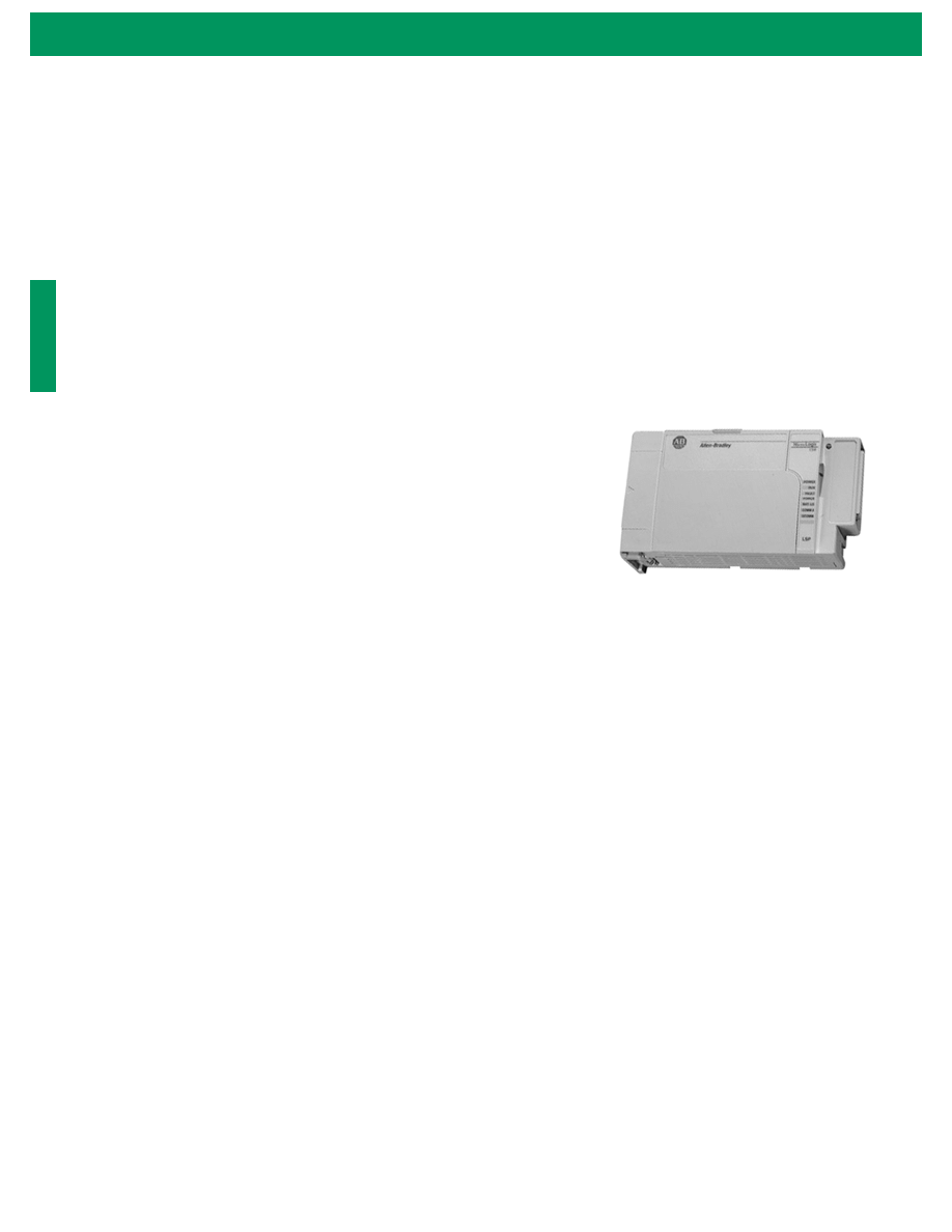
The MicroLogix 1500 is a world-class
programmable logic control platform with
advanced features and performance. Many
of these new features allow this controller to
be used in applications where much larger
controllers were required in the past.
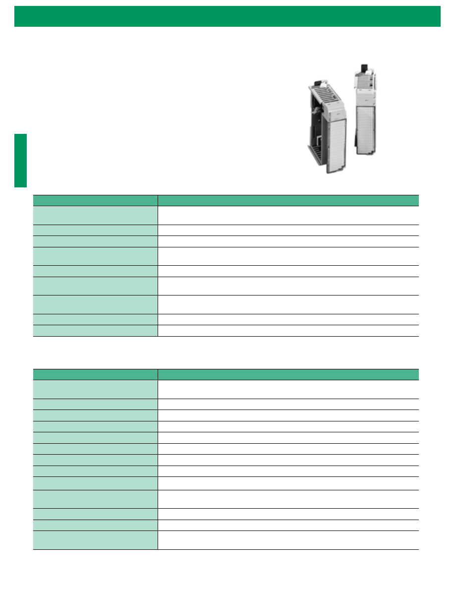
The MicroLogix 1500 controller features an
innovative two-piece design with a small
footprint. The processor and base units slide
together to form the complete controller.
The processor and base are independently
replaceable, allowing you to maximize your
embedded I/O options while minimizing
inventory stocking costs.
The MicroLogix 1500 uses Compact
™
I/O modules to further expand the
embedded I/O offerings, as well as to
provide the additional flexibility to cover a
wide range of applications. This high-
performance modular and rackless I/O
platform provides front accessibility for
removal and insertion, lowering system cost
and reducing maintenance time.
The MicroLogix 1500 system also utilizes
Rockwell Software RSLogix
™
500
programming software, and features an
instruction set common to the MicroLogix
1000, MicroLogix 1200 and SLC families
of controllers. This allows you to choose
just the right level of control using the same
programming tool.
A field-upgradeable flash operating system
ensures you will always be up to date with
the latest features. The controller may be
easily updated with latest firmware via web
site download.
Program portability of user programs
(upload, download and transport) is
accomplished via Memory Modules. Real-
Time Clock (RTC) modules provide
scheduling of control capability.
The optional Data Access Tool (DAT) plug-
in device offers you the ability to digitally
monitor and adjust 48 integer and 48 bit
locations for on-the-fly adjustment. Two
additional function keys each act as
momentary and toggle push buttons.
Security features may be used to protect
data from operator changes.
6
MicroLogix 1500 Programmable Controller with Compact I/O for Expansion
Product Overview
The MicroLogix 1500 controllers are comprised of a base unit, processor unit and optional expansion I/O. (See page
page 10 for additional information on expansion I/O.) Each component is optimized for functionality, while maintaining
affordability and a small size.
Processor Units
The processor units are the “brains” of the system. They provide the logic processing and the interface to the DAT, real-
time clock and memory modules, trim potentiometers, mode switch, and (using the 1764-LRP processor) an electrically
isolated RS-232 port (channel 1). The two processor units currently available are described below.
1764-LSP Processor
•
The 1764-LSP processor provides you with large memory size (greater
than 7K user program capacity) to solve a variety of applications.
Configurable user data allows data elements to be selected according to
the individual application requirements. 100% retentative data ensures
data integrity even during power loss.
•
Communications are extremely flexible with support for a variety of
protocols including DF1 Full-Duplex and Half-Duplex Slave, DH-485,
Modbus RTU Slave and ASCII. The RS-232 port on the base unit allows
for direct connection of programming and operator interface devices,
remote programming, peer-to-peer communications, and SCADA/RTU
networking. Modbus RTU Slave allows for easy integration with existing
SCADA/RTU installation utilizing Modbus protocol.
•
Static data file protection prevents user data from being altered via communication.
•
ASCII read/write capability enables you to initiate modem control
and
communicate to bar code readers, printers,
weigh scales, etc., with string data file support.
•
The 1764-LSP processor also provides you with the interface to the following advanced features and functionality:
– Optional memory and real-time clock modules
– Optional data access tool (1764-DAT)
– Built-in analog trim potentiometers
– Battery (built-in and replacement)
– 1 ms Selectable Timed Interrupt (STI) (For additional information on high-speed functions, see page 21.)
– High-resolution timers (For additional information on high-speed functions, see page 21.)
– Latching (pulse-catch) inputs (For additional information on high-speed functions, see page 21.)
– Communication toggle push button
– Mode switch for Run/Remote/Program
– Field upgradeable flash operating system
7
MicroLogix 1500 Programmable Controller with Compact I/O for Expansion
1764-LRP Processor
The 1764-LRP processor has all of the advanced features of the 1764-LSP processor
with the following additional functionality.
•
The 1764-LRP processor provides you with an even larger memory size (12K
user program capacity) to solve a variety of applications. Configurable user
data allows data elements to be selected according to the individual application
requirements. 100% retentative data ensures data integrity even during power
loss.
•
Communications are extremely flexible with a built-in isolated 9-pin D-shell
RS-232C port on the processor unit (in addition to the port on the base unit).
Both ports support: DF1 Full-Duplex and Half-Duplex Slave; DH-485;
Modbus RTU Slave; and ASCII. The RS-232 port allows for direct connection
of programming and operator interface devices, remote programming, peer-to-peer communications, and SCADA/
RTU networking. Modbus RTU Slave allows for easy integration with existing SCADA/RTU installation utilizing
Modbus protocol. This additional RS-232 communication port provides programming access, direct connection to
operator interface and other devices and networking, independent of the base communication port.
•
Two additional memory modules are available for larger 1764-LRP programs.
•
Data logging instruction stores up to 48K bytes of data records. Allows critical data to be stored for later analysis.
The new data logging instruction is also great for SCADA/RTU applications where a stand-alone controller must
collect information for later retrieval.
– The memory used for data logging is independent of processor memory. Within this memory, you can define up
to 256 data logging queues. Each queue is configurable by size (maximum number of records stored), and by
length (up to 80 characters). The length and the maximum number of records determine how much memory is
used by each queue. You can choose to have one large queue or multiple smaller ones.
– Each record is stored when the DLG instruction is executed and is stored in non-volatile memory (battery-
backed) to prevent loss during power-down.
– The configuration of the DLG instruction allows you to optionally include time stamping, data stamping, and a
configurable separator character with the data words that are stored.
– New records are appended to the end of the file - FIFO (first in, first out) as the DLG instruction is triggered (by
an event, timer, counter, real-time clock, etc.)
– Data logging records may be uploaded using a number of free tools available on the MicroLogix Internet site
http://www.ab.com/micrologix
. Tools are available for Palm OS, Windows CE, Windows
®
95, Windows
®
98,
and Windows NT™ (v4.0) devices to upload the data directly from the controller through comms. The
information may be imported directly into spreadsheet, word processing, or other applications as a .CSV or .TXT
file.
Base Units
MicroLogix 1500 base units house embedded inputs, outputs, power supply and the channel 0 port. They also provide the
interface to expansion I/O when required by an application. Three base units are available with the following electrical
configurations. (For information on base unit specifications, see page 8.)
•
120/240V ac powered base units
– 1764-24AWA - (12) 120V ac inputs and (12) relay outputs
– 1764-24BWA - (12) 24V dc inputs and (12) relay outputs
•
24V dc powered base unit
– 1764-28BXB - (16) 24V dc inputs and (6) 24V dc FET and (6) relay outputs
8
MicroLogix 1500 Programmable Controller with Compact I/O for Expansion
MicroLogix 1500 Specifications
Available Controllers
Base Unit General Specifications
Base Unit Input Specifications
Catalog Number
Description
Processor: (required, must be interfaced to a base unit, see below)
1764-LSP
Greater than 7K user memory
1764-LRP
12K user memory/RS-232 isolated Comm port/data logging
Base: (one of the following bases is required, for each processor)
1764-24AWA
AC Powered, 12 AC IN / 12 Relay Out
1764-24BWA
AC Powered, 12 DC IN / 12 Relay Out
1764-28BXB
24V DC Powered, 16 DC IN / 6 Relay and 6 DC FET Out
Description
1764-24BWA
1764-24AWA
1764-28BXB
Line Power
85/265V ac
20.4 to 30V dc
Power Supply Max Inrush
120V ac = 25A for 8 ms
240V ac = 40A for 4 ms
24V dc = 4A for 150 ms
User Power Output
24V dc at 400 mA, 400 µf max.
None
Input Circuit Type
24V dc, sink/source
120V ac
24V dc, sink/source
Output Circuit Type
Relay
6 Relay
6 FET transistor
Operating Temp.
+0°C to +55°C (+32°F to +131°F) ambient
Operating Humidity
5% to 95% relative humidity (non-condensing)
Vibration
Operating: 10 to 500 Hz, 5G, 0.030 in. peak-to-peak
Relay Operation: 2G
Shock (without Data Access Tool
installed)
Operating: 30G panel mounted (15G DIN Rail mounted)
Relay Operation: 7.5G panel mounted (5G DIN Rail mounted)
Non-Operating: 40G panel mounted (30G DIN Rail mounted)
Shock (with Data Access Tool
installed)
Operating: 20G panel mounted (15G DIN Rail mounted)
Relay Operation: 7.5G panel mounted (5G DIN Rail mounted)
Non-Operating: 30G panel mounted (20G DIN Rail mounted)
Agency Certification
UL 508
C-UL under CSA C22.2 no. 142
Class I, Div. 2, Groups A, B, C, D
(UL 1604, C-UL under CSA C22.2 no. 213)
CE compliant for all applicable directives
User Manual
MicroLogix 1500 Programmable Controllers User Manual, publication 1764-UM001A-US-P.
Description
1764-24AWA
1764-24BWA and 1764-28BXB
Inputs 0 thru 7
Inputs 8 and Higher
On-State Voltage Range
Operating Voltage Range
79 to 132V ac
14 to 30.0 V dc at 30°C (86°F)
14 to 26.4 V dc at 55°C (131°F)
10 to 30.0 V dc at 30°C (86°F)
10 to 26.4 V dc at 55°C (131°F)
Operating Frequency
47 Hz to 63 Hz
0 Hz to 20 KHz
0 Hz to 1 KHz
(1)
(1) Scan-time dependent.
9
MicroLogix 1500 Programmable Controller with Compact I/O for Expansion
Relay Contact Rating Table 1764-24AWA, -24BWA, -28BXB
Output Specifications - Maximum Continuous Current
1764-28BXB FET Output Specifications
Maximum Volts
Amperes
Amperes Continuous
Voltamperes
Make
Break
Make
Break
240V ac
7.5A
0.75A
2.5A
1800VA
180VA
(2)
(2) The total load controlled by the 1764-24AWA and 1764-24BWA is limited to 1440VA (break).
120V ac
15A
1.5A
125V dc
0.22A
(1)
(1) For dc voltage applications, the make/break ampere rating for relay contacts can be determined by dividing 28 VA by the applied dc voltage. For example, 28 VA/48V dc = 0.58A.
For dc voltage applications less than 14V, the make/break ratings for relay contacts cannot exceed 2A.
1.0A
28VA
24V dc
1.2A
1
2.0A
28VA
Specification
1764-24AWA/-24BWA
1764-28BXB
Current per Common
8A
8A
Current per Controller
at 150V ac Maximum
24A
18A
at 240V ac Maximum
20A
18A
Specification
General Operation
(Outputs 2 thru 7)
High-Speed Operation
(1)
(Outputs 2 and 3 Only)
(1) Outputs 2 and 3 are designed to provide increased functionality over the other FET outputs (4 through 7). They may be used like the other FET transistor outputs, but in addition,
within a limited current range, they may be operated at a higher speed. Outputs 2 and 3 also provide a pulse train output (PTO) or pulse width modulation output (PWM) function.
User Supply Voltage
Minimum
20.4V dc
20.4V dc
Maximum
26.4V dc
26.4V dc
Current Rating per Point
Maximum load
1A at 55°C (131°F)
1.5A at 30°C (86°F)
100 mA
Surge Current per Point
Peak current
4.0A for 10 msec
Not Applicable
Current per Common
Maximum total
6A
6A
Off to On Response
Maximum
0.1 msec
6 µsec
On to Off Response
Maximum
1.0 msec
18 µsec
MicroLogix 1500 Programmable Controller with Compact I/O for Expansion
0
Features
•
Modular system, modules to suit the application
•
Feature-rich I/O to address a wide range of applications
•
Rackless design, reduces system components
•
Small footprint, shrinks panel space requirements
•
Front insertion and removal, reducing assembly and
replacement time
•
Unique tongue-and-groove interlocking case design, ensures a
strong, mechanical connection between modules
•
Software keying, prevents incorrect module placement within a
system
•
Discrete, analog and relay output modules
Currently available modules include:
1769-IA16
16-point 120V ac Input Module
1769-IA8I
8-point Individually Isolated 120V ac Input Module
1769-OA8
8-point 120/240V ac Output Module
1769-IM12
12-point 240V ac Input Module
1769-IQ16
16-point 24V dc Sinking/Sourcing Input Module
1769-OB16
16-point 24V dc Sourcing Output Module
1769-OB16P
(1)
(1) Planned availability in August 2000.
16-point 24V dc Sourcing Output Module with Electronic
Protection
1769-OV16
16-point 24V dc Sinking Output Module
1769-OW8
8-point ac/dc Relay Output Module
1769-OW8I
8-point Individually Isolated ac/dc Relay Output Module
1769-IQ6XOW4
Combination 6-point dc Input and 4-point Relay Output
Module
1769-IF4
4-channel analog current/voltage Input Module
1769-OF2
2-channel analog current/voltage Output Module
Expansion I/O Modules
High-density Bulletin 1769 Compact I/O
rackless expansion modules offer superior
functionality and high value at a
competitive price. With a variety of
modules, they complement and extend the
capabilities of the MicroLogix 1500
controller by maximizing flexibility of the
I/O count and type. (Up to eight
expansion Compact I/O modules can be
connected to a MicroLogix 1500
controller dependent on power
requirements.) Compact I/O provides an
excellent platform for future
enhancements, so you can easily choose
the level of control as your application
needs grow.
Compact I/O’s analog modules provide
14-bit plus sign maximum resolution,
making them an excellent choice in
applications where the need to detect
small changes is vital.
Similarly, Compact I/O analog modules
can be used in applications where accuracy
is crucial. The modules share a high
accuracy rating of ±0.35% of full-scale
accuracy in the current mode. In the
voltage mode, the 1769-IF4 provides ±0.2
and the 1769-OF2 ±0.5% of full-scale
accuracy at 25
°
C.

1
MicroLogix 1500 Programmable Controller with Compact I/O for Expansion
Expansion I/O Module Specifications
Discrete Input Specifications
Discrete Output Specifications
1769-IQ6XOW4 Input and Output Specifications
Specification
1769-IM12
1769-IA16
1769-IQ16
1769-IA8I
Voltage Category
200/240V ac
100/120V ac
24V dc (sink/source)
100/120V ac
Voltage Range
159 to 265V ac
at 47 Hz to 60 Hz
79 to 132V ac
at 47 Hz to 63 Hz
10 to 30V dc at 30°C
(86°F)
10 to 26.4V dc at 60°C
(140°F)
79V ac to 132V ac at 47
Hz to 63 Hz
Number of Inputs
12
16
16
8
Number of Commons per Module
2
(1)
(1) This module has two internally connected common terminals.
2
(1)
2
8
Input Compatibility
IEC Type 1+
Specification
1769-OA8
1769-OB16 1769-OB16P 1769-OV16
1769-OW8 1769-OW8I
Voltage Category
100 to 240V ac
24V dc
24V dc
AC/DC
normally open relay
Operating Voltage Range
85 to 265V ac at 47 to
63 Hz
20.4 to 26.4V dc (source) 20.4 to 26.4V dc (sink)
5 to 265V ac
5 to 125V dc
Number of Outputs
8
16
8
Number of Commons per Module
2
1
2
8
Continuous Current per Point (max.)
0.25A at 60°C (140°F)
0.5A at 30°C (86°F)
0.5A at 60°C (140°F)
1.0A at 30°C (86°F)
2.5A
Continuous Current per Common (max.)
n/a
8A
2.5A
Continuous Current Per Module (max.)
2.0 A at 60°C (140°F)
4.0 A at 30°C (86°F)
4.0A at 60°C (140°F)
8.0A at 30°C (86°F)
16A
Specifications
1769-IQ6XOW4
Voltage Category
24V dc (sink/source) inputs
AC/DC normally open relay outputs
Operating Voltage Range
inputs: 10 to 30V dc at 30°C (86°F)
inputs: 10 to 26.4V dc at 60°C (140°F)
outputs: 5 to 265V ac
outputs: 5 to 125V dc
Number of Inputs
6
Number of Outputs
4
Number of Commons per Module
2 (one for inputs, one for outputs)
Input Compatibility
IEC Type 1+
Continuous Current per Point (max.)
2.5A (outputs)
Continuous Current per Common (max.)
8A (outputs)
2
MicroLogix 1500 Programmable Controller with Compact I/O for Expansion
Analog I/O Modules
Compact I/O offers two analog I/O choices:
•
1769-IF4 - 4-channel current or voltage input
•
1769-OF2 - 2-channel current or voltage output
Each channel on both the 1769-IF4 and 1769-OF2 modules has the ability
to be individually configured for either current (4 to 20 mA or 0 to 20 mA)
or voltage (
±
10V dc, 0 to 10V dc, 0 to 5V dc or 1 to 5V dc) input/output.
This provides application flexibility, reduces stock inventory and lessens the
learning curve.
1769-IF4 Input Specifications
1769-OF2 Output Specifications
Specification
1769-IF4
Analog Normal Operating Ranges
Voltage: ±10V dc, 0 to 10V dc, 0 to 5V dc, 1 to 5V dc
Current: 0 to 20 mA, 4 to 20 mA
Number of Inputs
4 differential or single-ended
Resolution (max.)
14 bits minimum (unipolar) 14 bits plus sign (bipolar), with 50 or 60 Hz filter selected
Normal Mode Rejection Ratio
Voltage: -10 dB at 50 Hz, -12 dB at 60 Hz
Current: -15 dB at 50 Hz, -18 dB at 60 Hz
Input Impedance
Voltage Terminal: 200K
Ω,
Current Terminal: 250
Ω
Overall Accuracy
(1)
(1) Includes offset, gain, non-linearity and repeatability error terms.
Voltage Terminal: ±0.2% full scale at 25°C
Current Terminal: ±0.35% full scale at 25°C
Module Error over Full Temperature Range
(0 to +60°C [+32°F to +140°F])
Voltage: ±0.3%
Current: ±0.5%
Field Input Calibration
Not required
Channel Diagnostics
Over- or under-range by bit reporting
Specification
1769-OF2
Analog Ranges
Voltage: ±10V dc, 0 to 10V dc, 0 to 5V dc, 1 to 5V dc
Current: 0 to 20 mA, 4 to 20 mA
Number of Outputs
2 single-ended
Resolution (max.)
14 bits minimum (unipolar) 14 bits plus sign (bipolar), with 50 or 60 Hz filter selected
Conversion Rate (all channels) max.
2.5 ms
Current Load on Voltage Output
5 mA max.
Resistive Load on Current Output
0 to 500
Ω
(includes wire resistance)
Load Range on Voltage Output
> 1k
Ω
at 5V dc; > 2k
Ω
at 10V dc
Field Calibration
None required
Overall Accuracy
(1)
(1) Includes offset, gain, non-linearity and repeatability error terms.
Voltage Terminal: ±0.5% full scale at 25°C, Current Terminal: ±0.35% full scale at 25°C
Output Error Over Full Temperature Range
(0 to 60°C [32 to +140°F])
Voltage: ±0.8%
Current: ±0.55%
Open/Short-Circuit Overvoltage Protection
Yes
Output Overvoltage Protection
Yes
Channel Diagnostics
Over-or-under range by bit reporting
output wire broken or load resistance high by bit reporting (current mode only)
1
MicroLogix 1500 Programmable Controller with Compact I/O for Expansion
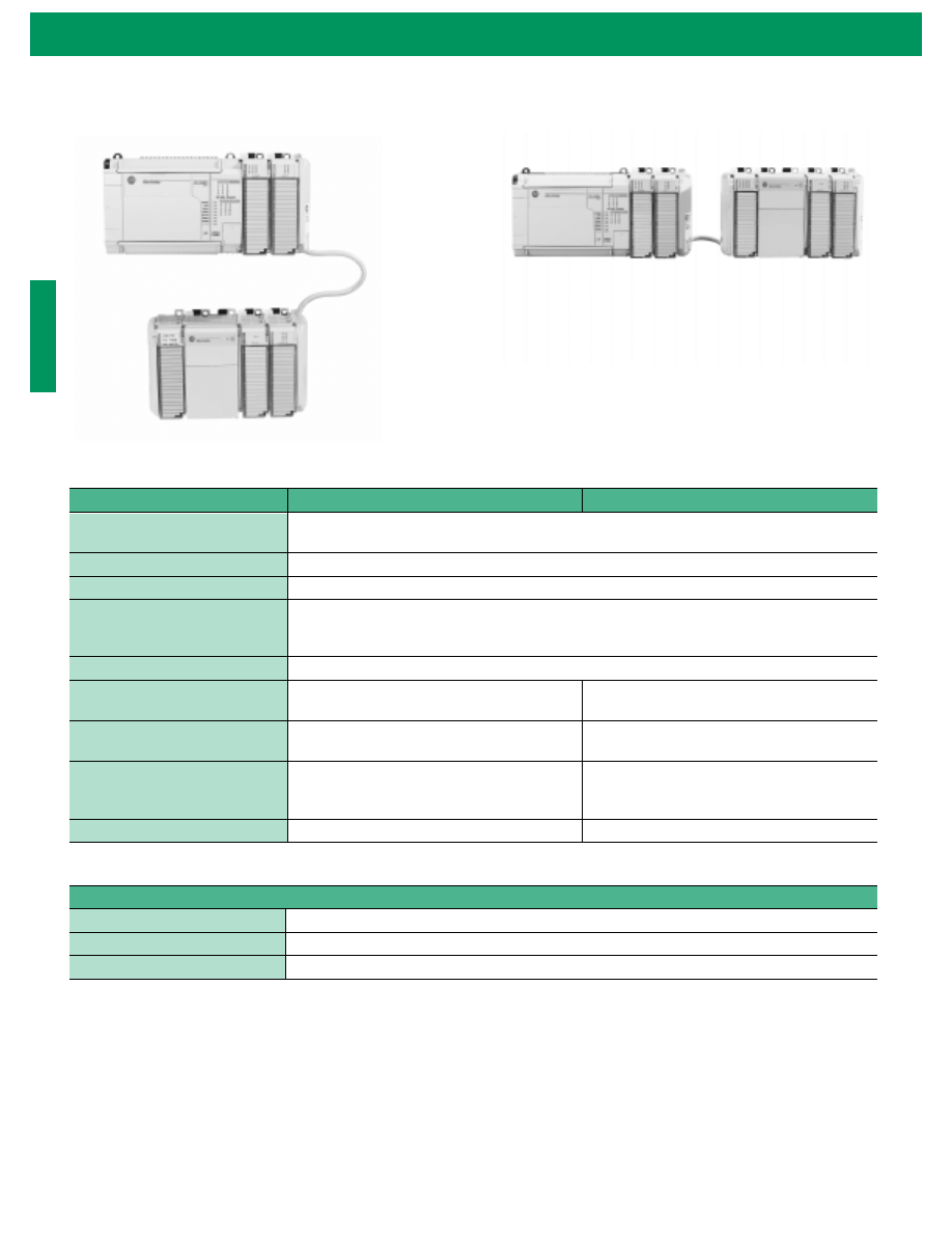
MicroLogix 1500 System Expansion
With MicroLogix 1500 Operating System Revision Number (FRN)
3 or later, you can connect an additional bank of I/O to your
controller.
In a MicroLogix 1500 system, a maximum of one 1769 Expansion
cable can be used, allowing for two banks of I/O modules (one
connected directly to the controller and the other connected via the
cable). Each I/O bank
(1)
requires its own power supply (Bank 0 uses
the controller’s embedded power supply).
Only one power supply (embedded or expansion) may be used on an
I/O bank. The expansion power supply cannot be connected directly
to a controller that has an embedded power supply, such as the
MicroLogix 1500. It must be connected using one of the expansion
cables. (See photos on page 14.)
Checking the MicroLogix 1500 Firmware
To use the MicroLogix 1500 controller with a 1769 Expansion
I/O power supply, verify that you have the following:
•
MicroLogix 1500 Processor (Catalog Number 1764-LSP,
Series A, Revision C or higher)
•
Operating System Version: Firmware Revision Number (FRN)
3 or higher
You can check the FRN by looking at word S:59 (Operating System
FRN) in the status file.
If your processor is at an older revision, you must upgrade the
operating system to FRN 3 or higher to use an expansion cable and
power supply. On the internet, go to
http://www.ab.com/micrologix
to download the operating system upgrade. Enter MicroLogix 1500;
go to Tools and Tips.
(1) An I/O bank is a group of I/O modules connected directly to one another. Banks are separated by
cables.
Expansion Power Supplies
and Cables
Using an expansion I/O power supply
increases the system’s capacity for adding
expansion I/O modules, such as the
1769-IF4 and 1769-OF2 analog modules.
You can visit the MicroLogix web site to
obtain an electronic worksheet to assist
you with system expansion validation
using 1769 power supplies and Bus
communication cables. On the Internet,
go to
http://www.ab.com/micrologix
.
Enter MicroLogix 1500; go to Tools and
Tips, Expansion I/O System Qualifier.
4
MicroLogix 1500 Programmable Controller with Compact I/O for Expansion
Vertical Orientation
Expansion Power Supplies Specifications
Expansion Cable Specifications
Specification
1769-PA2
1769-PB2
Dimensions
118 mm (height) x 87 mm (depth) x 70mm (width); height including mounting tabs is 138 mm.
4.65 in. (height) x 3.43 in (depth) x 2.76 in (width); height including mounting tabs is 5.43 in.
Operating Temperature
0°C to +60°C (32°F to +140°F)
Operating Humidity
5% to 95% non-condensing
Agency Certification
C-UL certified (under CSA C22.2 No. 142)
UL 508 listed
CE compliant for all applicable directives
Hazardous Environment Class
Class I, Division 2, Hazardous Location, Groups A, B, C, D (UL 1604, C-UL under CSA C22.2 No. 213)
Voltage Range
85 to 265V ac (no jumper or DIP switch required)
47 to 63 Hz
19.2 to 31.2V dc
Maximum Line Requirement
100 VA at 120V ac
130 VA at 240V ac
50 VA at 24V dc
Short Circuit Protection
Front Access Fuse
(Replacement part number: Wickmann 19195-3.15A
Wickmann 19343-1.6A, or Wickmann 19181-4A)
Front Access Fuse
(Replacement part number: Wickmann 19193-6.3A)
+24V dc User Voltage Range
20.4V dc to 26.4V dc
NA
Specification
Operating Temperature
0°C to +60°C (32°F to +140°F)
Operating Humidity
5% to 95% non-condensing
Hazardous Environment Class
Class I, Division 2, Hazardous Location, Groups A, B, C, D (UL 1604, C-UL under CSA C22.2 No. 213)
Expansion I/O
Bank 0
1769-CRRx
(1)
Expansion Cable
Expansion I/O
Bank 1
1769-ECL
End Cap
Expansion
I/O Bank 0
Expansion
I/O Bank 1
1769-CRRx
(1)
Expansion Cable
(1) The x in this catalog number can be either a 1 or a 3 representing the length of the cable:
1 = 1 foot (305 mm) and 3 = 3.28 feet (1 meter).
Horizontal Orientation
1
MicroLogix 1500 Programmable Controller with Compact I/O for Expansion
Features
•
One RS-232 port (available on all base units)
•
Additional RS-232 port (available when using catalog number
1764-LRP)
•
300, 600, 1200, 4800, 9600, 19,200, and 38,400 baud rates
•
RTS/CTS Hardware handshake signals - channel 0
•
RTS/CTS/DCD Hardware handshake signals - channel 1
•
Connection to DH-485 and DeviceNet networks through
1761-NET-AIC and 1761-NET-DNI, respectively
•
Connection to modems for remote communications
•
ASCII messaging provides dial-out capability
The MicroLogix 1500 allows you to choose the network that best
meets your needs.
If your application requires:
Use this network
•
Connection of low-level multi-vendor devices directly to plant
floor controllers
•
Data sharing between 64 devices
•
Better diagnostics for improved data collection and fault
detection
•
Less wiring and reduced start-up time than traditional, hard-
wired systems
DeviceNet via the
1761-NET-DNI
•
Plant-wide and cell-level data sharing with program
maintenance
•
Data sharing between 32 controllers
•
Program upload, download, and monitoring to all controllers
•
Compatibility with multiple Allen-Bradley HMI devices
DH-485 via the
1761-NET-AIC
•
Connection to dial-up modems for remote program
maintenance or data collection
•
Connection to leased-line or radio modems for use in SCADA
systems
•
Remote Terminal Unit (RTU) functions
DF1 Full-Duplex
DF1 Half-Duplex
Slave
•
Connection to modems for remote data collection in a SCADA
system
•
Remote Terminal Unit (RTU) functions
Modbus RTU Slave
MicroLogix
1200
MicroLogix
1500
Flex I/O
Filter
MicroLogix
1200
MicroLogix
1000
WorkStation
SLC
Controller
SCADA Master
Variable
Frequency Drive
System
Radio/Phone Modem
DC
Drive
MicroLogix
1000
MicroLogix
1200
MicroLogix
1500
Reliance
AC Motor
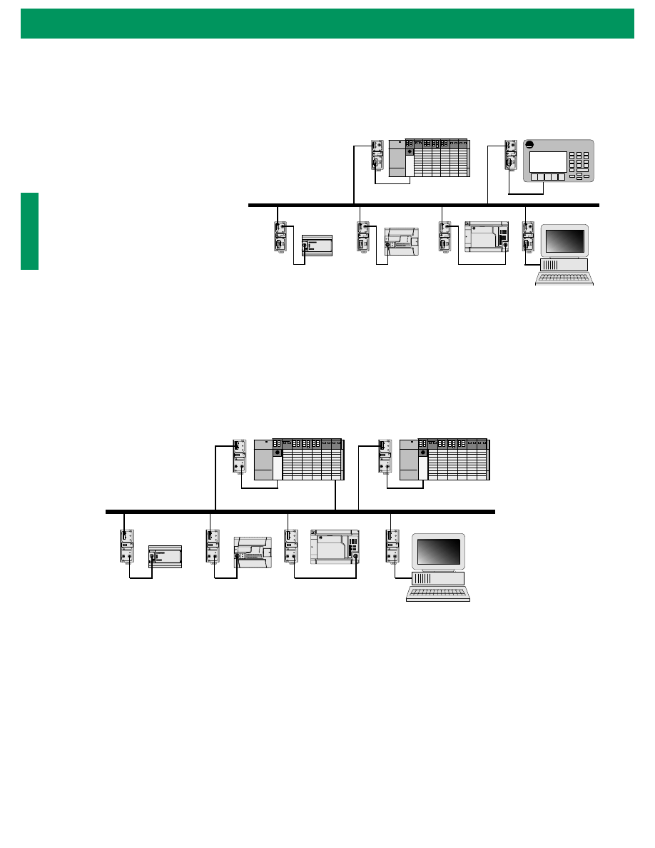
Communication Choices
All MicroLogix 1500 programmable
controllers provide several communication
options to fit into a variety of applications.
The addition of a second full-function
RS-232 communications port (catalog
number 1764-LRP)
enables two
communication devices to be connected
to the controller simultaneously (e.g.
ASCII device, operator interface device,
modem or programming device).
The DF1 Full-Duplex protocol allows a
MicroLogix 1500 to communicate directly
with another device, such as a personal
computer or an operator interface device.
The DF1 Full-Duplex protocol (also
referred to as DF1 point-to-point
protocol) is useful where RS-232 point-to-
point communication is required.
The DH-485 multi-drop communication
capability allows you to network up to 32
MicroLogix or SLC 500 controllers,
Human/Machine Interface (HMI) devices
and/or personal computers using peer-to-
peer messaging.
And, the MicroLogix 1500 can
communicate on a DeviceNet network as
well. DeviceNet digitally links push
buttons, sensors, actuators, PLCs and
other industrial devices on an open
network.
MicroLogix 1500 controllers also support
DF1 Half-Duplex Slave communications
for use in SCADA systems as a Remote
Terminal Unit (RTU). This open network
protocol enables MicroLogix controllers to
communicate as responder (slave) nodes
on DF1 master/slave networks. DF1
supports up to 254 responder devices with
a single master.
Additionally, the MicroLogix 1500
supports Modbus Slave, a SCADA/RTU
protocol.
6
MicroLogix 1500 Programmable Controller with Compact I/O for Expansion
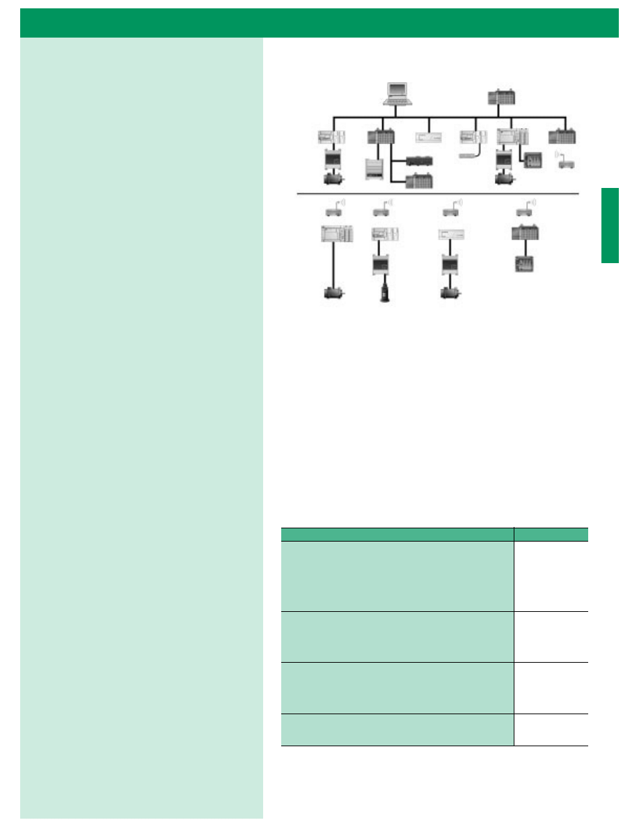
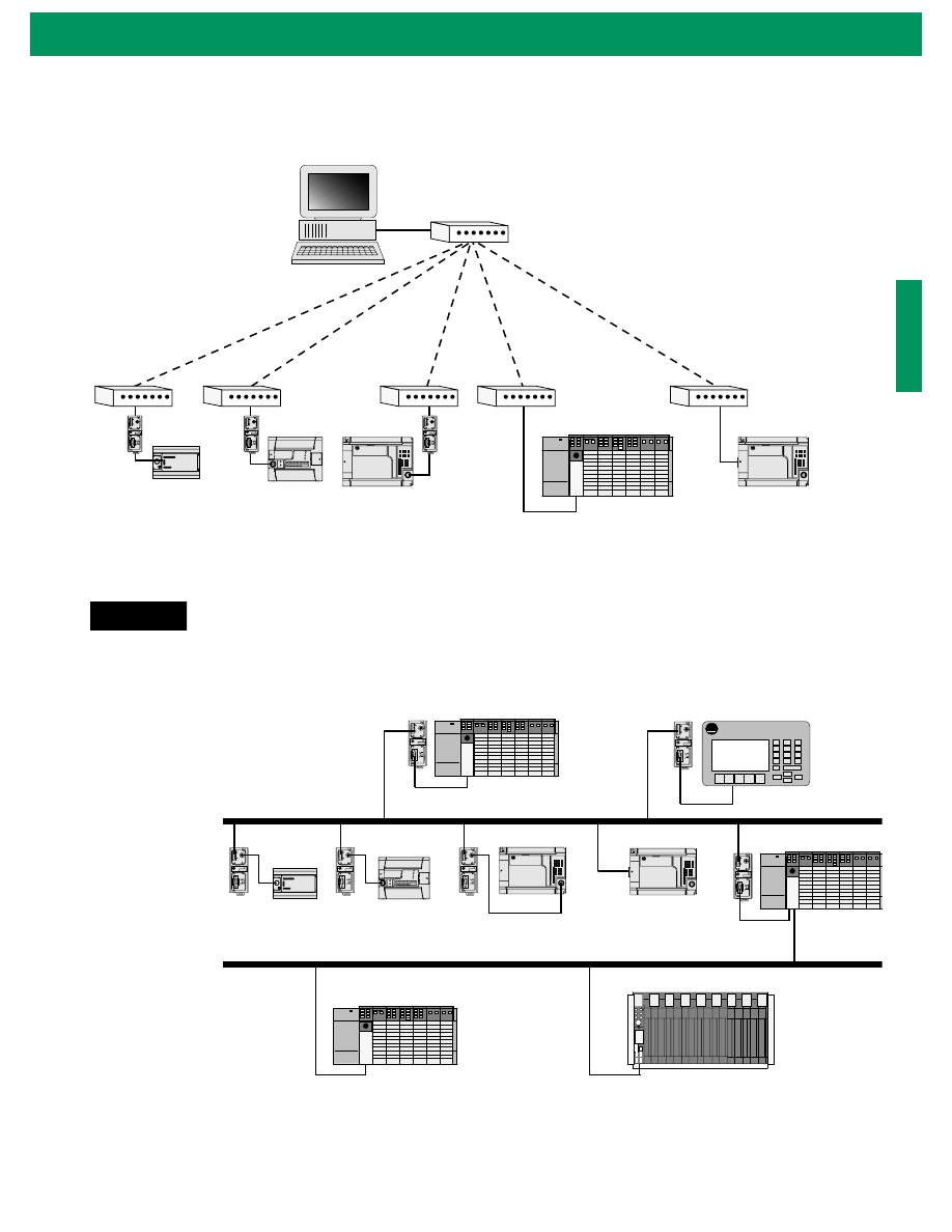
Local Messages
The MicroLogix 1500 is capable of
communicating using local or remote
messages. With a local message, all network
devices are accessible without a separate
device acting as a bridge. With remote
messages, devices are accessible by passing
or routing through a device.
The following four examples represent
different types of local and remote
networks.
Example 2 - Local DeviceNet Network with DeviceNet Interface (1761-NET-DNI)
Example 1 - Local DH-485 Network with AIC+ (1761-NET-AIC) Interface
A-B
PanelView
TERM
A
B
COM
SHLD
CHS GND
TX
TX
PWR
TX
DC SOURCE
CABLE
EXTERNAL
TERM
A
B
COM
SHLD
CHS GND
TX
TX
PWR
TX
DC SOURCE
CABLE
EXTERNAL
TERM
A
B
COM
SHLD
CHS GND
TX
TX
PWR
TX
DC SOURCE
CABLE
EXTERNAL
TERM
A
B
COM
SHLD
CHS GND
TX
TX
PWR
TX
DC SOURCE
CABLE
EXTERNAL
TERM
A
B
COM
SHLD
CHS GND
TX
TX
PWR
TX
DC SOURCE
CABLE
EXTERNAL
TERM
A
B
COM
SHLD
CHS GND
TX
TX
PWR
TX
DC SOURCE
CABLE
EXTERNAL
AIC+
AIC+
AIC+
DH-485 Network
SLC 5/04
PanelView 550
MicroLogix 1000
MicroLogix 1200
Personal
Computer
AIC+
AIC+
AIC+
MicroLogix 1500
DANGER
DANGER
DANGER
DANGER
DANGER
DANGER
DNI
DNI
DNI
DNI
DeviceNet Network
Master
SLC 5/03
MicroLogix 1500
MicroLogix 1000
MicroLogix 1200
Personal
Computer
DNI
DNI
SLC 5/03
1
MicroLogix 1500 Programmable Controller with Compact I/O for Expansion
Example 3 - Local DF1 Half-Duplex Network
Example 4 - Remote Messaging
NOTE
It is recommended that isolation (1761-NET-AIC) be provided between the controller
and the modem when using a non-isolated port.
TERM
A
B
COM
SHLD
CHS GND
TX
TX
PWR
TX
DC SOURCE
CABLE
EXTERNAL
TERM
A
B
COM
SHLD
CHS GND
TX
TX
PWR
TX
DC SOURCE
CABLE
EXTERNAL
TERM
A
B
COM
SHLD
CHS GND
TX
TX
PWR
TX
DC SOURCE
CABLE
EXTERNAL
Rockwell Software WINtelligent
LINX, RSLinx 2.0 (or higher),
SLC 5/03, SLC 5/04, and SLC 5/05,
or PLC-5 processors configured for
DF1 Half-Duplex Master.
RS-232
(DF1 Half-Duplex Protocol)
MicroLogix 1500 with
1764-LSP or 1764-LRP
Processor (Slave)
SLC 5/03 (Slave)
MicroLogix
1000 (Slave)
MicroLogix 1500 with
1764-LRP Processor (Slave)
MicroLogix
1200 (Slave)
Modem
A-B
PanelView
TERM
A
B
COM
SHLD
CHS GND
TX
TX
PWR
TX
DC SOURCE
CABLE
EXTERNAL
TERM
A
B
COM
SHLD
CHS GND
TX
TX
PWR
TX
DC SOURCE
CABLE
EXTERNAL
TERM
A
B
COM
SHLD
CHS GND
TX
TX
PWR
TX
DC SOURCE
CABLE
EXTERNAL
TERM
A
B
COM
SHLD
CHS GND
TX
TX
PWR
TX
DC SOURCE
CABLE
EXTERNAL
TERM
A
B
COM
SHLD
CHS GND
TX
TX
PWR
TX
DC SOURCE
CABLE
EXTERNAL
TERM
A
B
COM
SHLD
CHS GND
TX
TX
PWR
TX
DC SOURCE
CABLE
EXTERNAL
AIC+
AIC+
AIC+
AIC+
DH-485 Network
SLC 5/04
PanelView 550
MicroLogix 1500 with 1764-LSP
or 1764-LRP Processor
MicroLogix 1000
MicroLogix 1200
SLC 5/04
AIC+
AIC+
SLC 5/04
PLC-5
DH+ Network
MicroLogix 1500 with
1764-LRP Processor
MicroLogix 1500 Programmable Controller with Compact I/O for Expansion
8
1761-NET-DNI DeviceNet Interface Module
Highlights of the DeviceNet Interface’s capabilities are:
•
Peer-to-peer messaging between Allen-Bradley controllers and
other devices using the DF1 Full-Duplex protocol
•
Programming and on-line monitoring over the DeviceNet
network
•
With a DNI connected to a modem, you can dial in to any
other DNI-controller combination on DeviceNet
•
Other DeviceNet products can send explicit (Get or Set)
messages with the DNI at any time
•
The controller can initiate an explicit message to any UCMM
(Unconnected Message Manager) compatible device on
DeviceNet
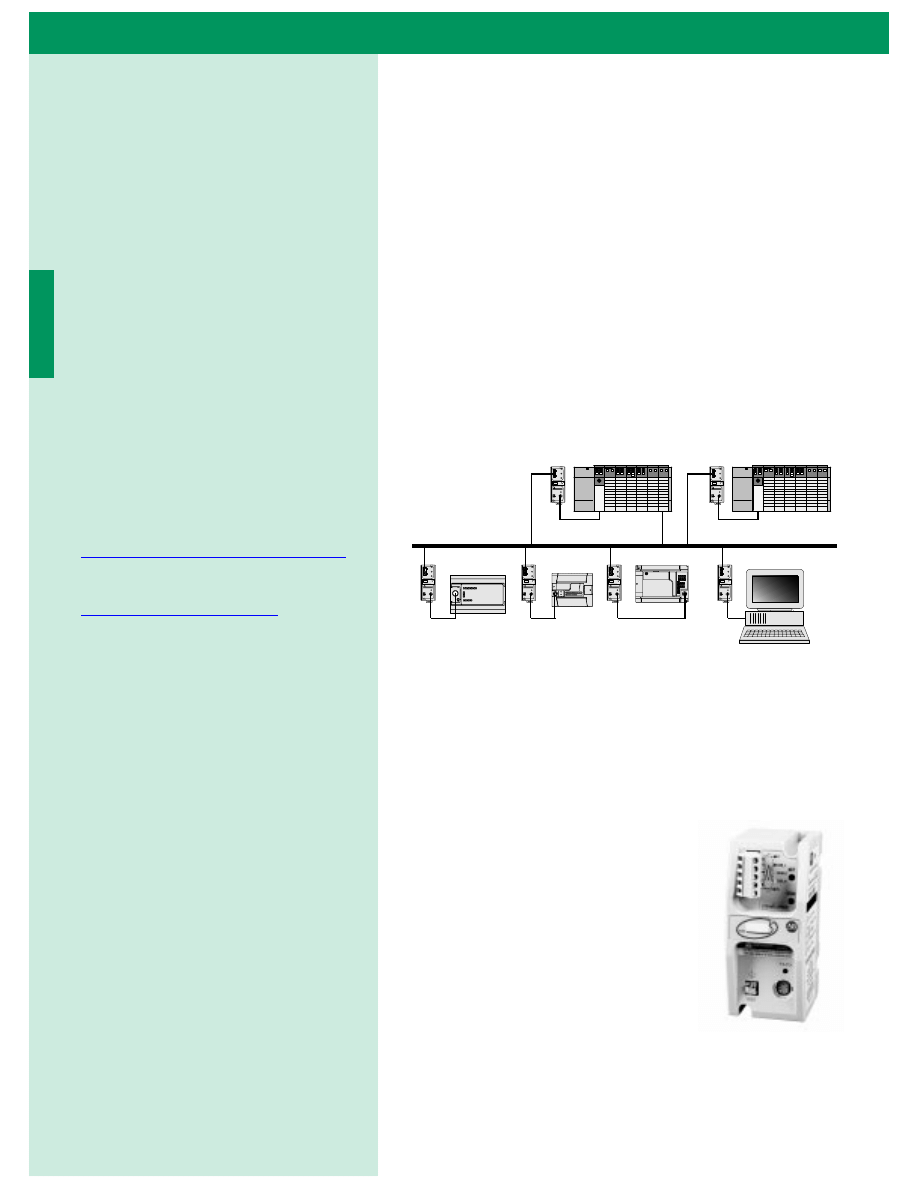
MicroLogix micro-PLCs extend the benefits of distributed control to
the device level of your process with the addition of DeviceNet
functionality.
DeviceNet digitally links push buttons, sensors, actuators, PLCs and
other industrial devices. It reduces the installation and maintenance
costs of multiple discrete wires with a single
cable that handles both communications and
power distribution.
The 1761-NET-DNI Series B Interface
(DNI) brings the fast response, low cost and
reliability of open DeviceNet connectivity to
all MicroLogix controllers and most other
Allen-Bradley controllers.
MicroLogix on DeviceNet lets you take
advantage of the latest advances in
communications. DeviceNet uses
producer/consumer technology which significantly reduces the
amount of traffic on the network, thus improving efficiency and data
throughput. As a result, information gets across the network quicker.
DANGER
DANGER
DANGER
DANGER
DANGER
DANGER
DNI
DNI
DNI
DNI
DeviceNet
Master
SLC 5/03
MicroLogix
1500
MicroLogix
1000
MicroLogix
1200
Personal
Computer
DNI
DNI
SLC 5/03
Network Interface Devices
The Micrologix 1500 Programmable
Controller’s list of impressive hardware,
memory, and processing features makes
this family of controllers an ideal choice
for mid-sized applications. Additionally,
with the 1761-NET-DNI DeviceNet
Interface and 1761-NET-AIC Advanced
Interface Converter (AIC+), you can
connect MicroLogix Programmable
Controllers to DH-485 and DeviceNet
networks.
For detailed information on using these
network interface modules, refer to the
DeviceNet
™
Interface User Manual,
publication 1761-6.5, or the AIC+
Advanced Interface Converter User Manual,
publication 1761-6.4. To purchase these
manuals or download a free electronic
version, visit us at
http://www.theautomationbookstore.com
.
For fast access to related publications, visit
the MicroLogix Internet site
http://www.ab.com/micrologix
. Electronic
versions of our manuals are available for
you to search and download.
1
MicroLogix 1500 Programmable Controller with Compact I/O for Expansion
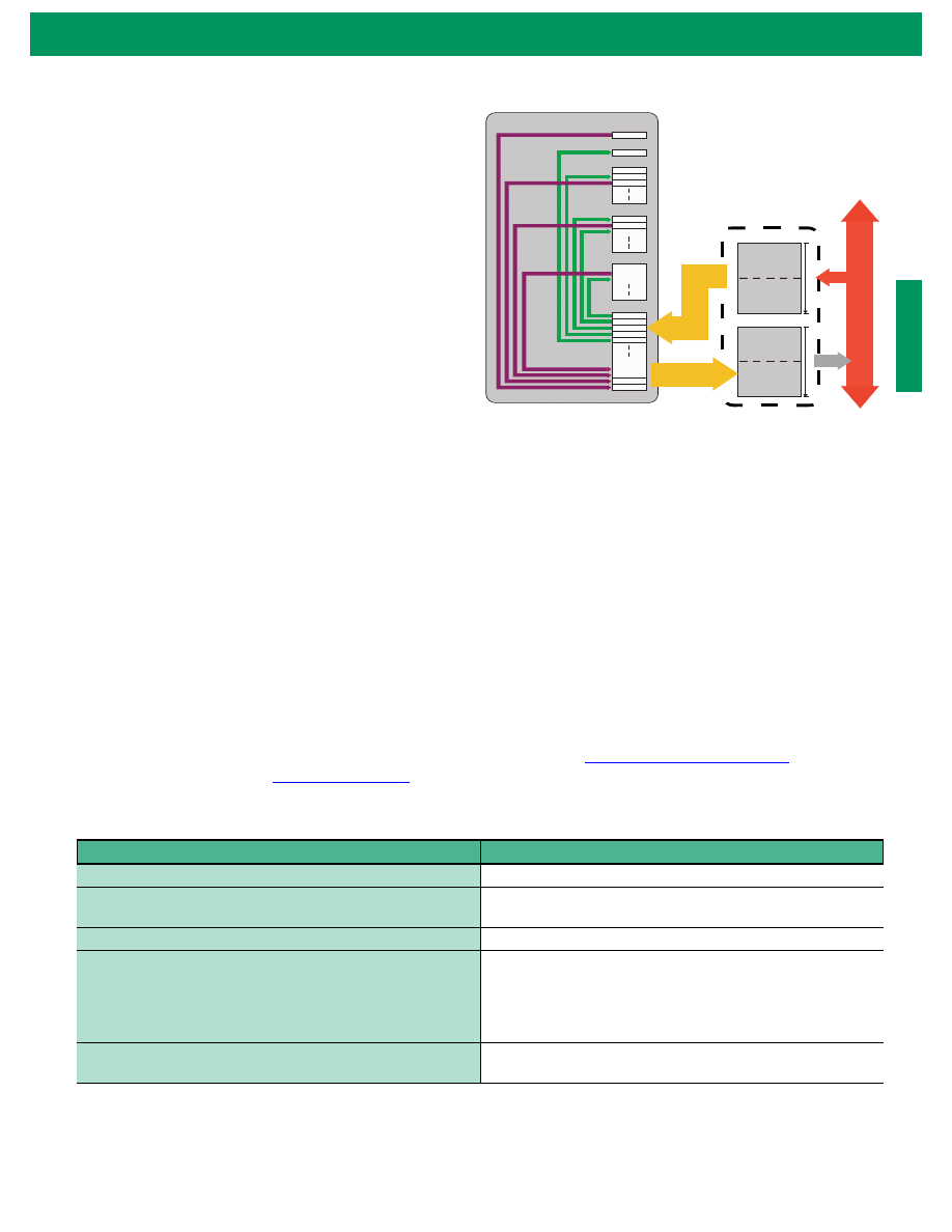
Advanced Slave I/O Functionality
Through the DNI, MicroLogix controllers can function as
cost-effective DeviceNet slave nodes. The DNI presents to
DeviceNet up to 64 words of data (32 inputs, 32 outputs,
configurable). The DNI can either poll or accept data sent
from the MicroLogix controller to keep its mapped I/O data
up-to-date with the actual data in the controller, while the
DNI handles all DeviceNet communications.
All local I/O remains under the MicroLogix controller’s direct
control, yet can be visible to the DeviceNet master.
Using standard messaging commands, you can easily read or
write data to other controllers as shown in the network
diagram on page 18.
Simple, Reliable Peer-to-Peer Messaging
The DNI brings brand-new functionality to DeviceNet by enabling peer-to-peer messaging between devices that use the
DF1 Full-Duplex protocol.
The DNI takes the DF1 Full-Duplex commands, wraps them in the DeviceNet protocol and sends them to the target
DNI. The target DNI removes the DeviceNet information and passes the DF1 command to the end device.
This capability works between controllers, PCs and controllers, and for program up/downloading. I/O and data messages
are prioritized, which minimizes I/O determinism problems typically encountered on networks that support I/O and
messaging simultaneously.
Enable Your Control Strategy Now
Helpful information and free DNI configuration software are also available at
http://www.ab.com/micrologix
. For more on
the DeviceNet standard, visit
http://www.odva.org
.
DeviceNet Interface Series B (1761-NET-DNI) Specifications
Description
Specifications
24V dc Power Source Requirements
11 to 25V dc
Current Draw
200 to 250 mA
400 mA maximum inrush current (30 msec, max.)
Operating Ambient Temperature
0 to +60°C (+32 to +140°F)
Agency Certification
UL 1604
C-UL C22.2 No. 213
Class 1, Division 2, Groups A, B, C, D
CE compliant for all applicable directives
ODVA conformance 2.0-A12
DeviceNet
maximum number of nodes = 64
maximum length = 500m at 125K baud or 100m at 500K baud
DeviceNet Network
0
1
2
3
4
to
16
0
1
2
3
to
40
Status
Timers
Counters
Inputs
DeviceNet Outputs
DNI Data
Mapping of integer blocks to
DNI I/O words done with
DeviceNet Manager software
Mapping of integer files
performed in ladder logic
Split point
adjustable
Master’s Outputs
Explicit Data
Explicit Data
Master’s Inputs
Outputs
Split point
adjustable
Integers
DeviceNet Inputs
64
w
o
rd
s m
a
x
.
64
w
o
rd
s m
a
x
.
0
MicroLogix 1500 Programmable Controller with Compact I/O for Expansion
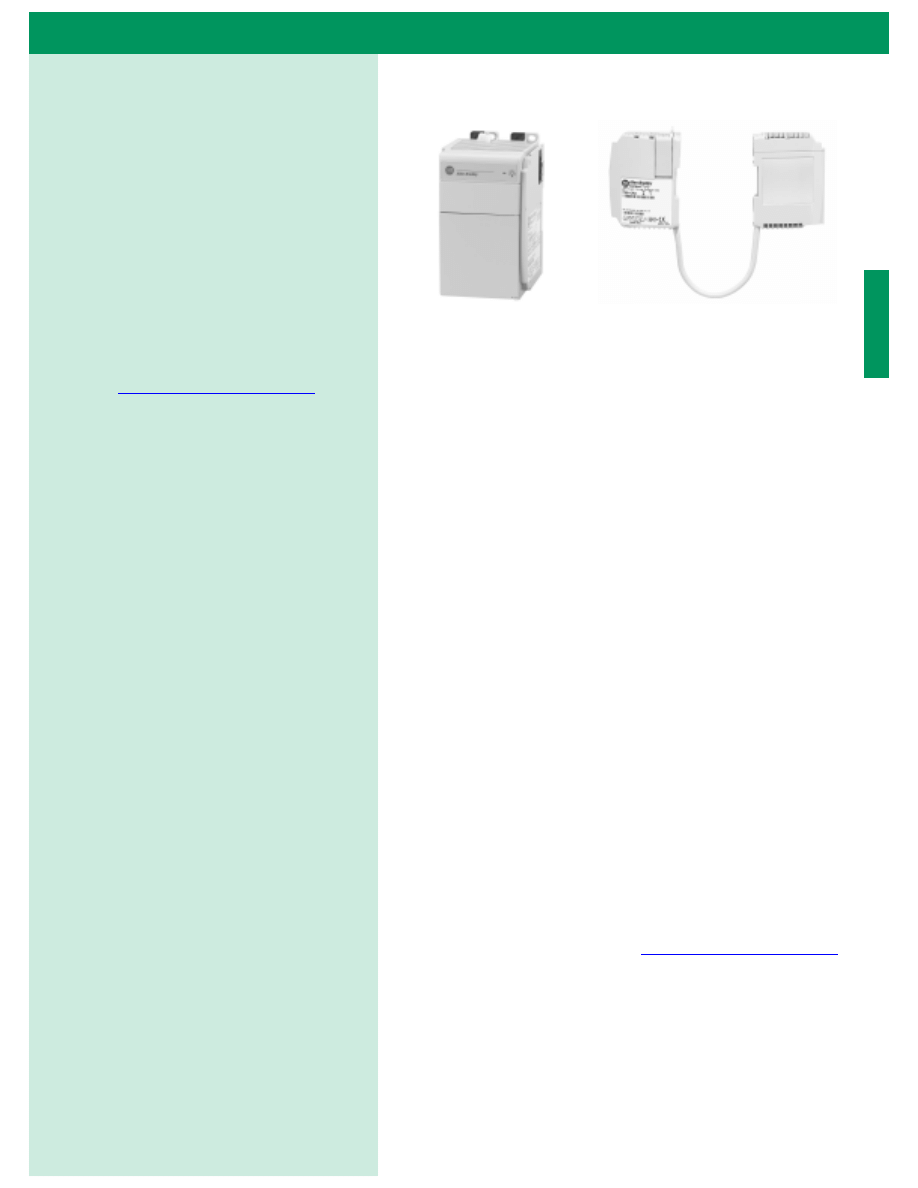
AIC+ Advanced Interface Converter
The AIC+ is a networking device from Allen-Bradley that provides DH-485 network access from
any DH-485 compatible device that has a RS-232 port, including all MicroLogix controllers,
SLC 5/03 and 5/04, and PanelView 550 and 900. In addition, the device provides isolation
between all ports for a more stable network and protection for connected devices. The unit is
DIN rail or panel mountable and is industrially hardened.
The Advanced Interface Converter provides a simple, cost-effective solution for connecting
RS-232 devices to a DH-485 network. The AIC+ also provides:
•
Two isolated RS-232 connections - one 9-pin D-shell and one 8-pin mini DIN
•
An RS-485 6-pin Phoenix connection
•
Accepts power via the 8-pin mini DIN from a MicroLogix controller or an external power
connection
•
Compatibility with existing SLC DH-485 networks that use 1747-AICs
•
Auto baud rate capability for ease of system set-up
•
Diagnostic LEDs for network activity
Some typical applications include:
•
Connecting a personal computer to a
DH-485 network
•
Connecting MicroLogix controllers to a
DH-485 network
•
Linking SLC 5/03 or SLC 5/04
processors using DF1 Half-Duplex
“master/slave” protocol. This allows you
to connect remote “islands” of
automation to a master controller to
upload diagnostic and status information.
Advanced Interface Converter (1761-NET-AIC) Specifications
Description
Specifications
24V dc Power Source Requirement
20.4 - 28.8V dc
Current Draw
120 mA
200 mA maximum inrush current
Operating Ambient Temperature
0 to +60°C (+32 to +140°F)
Agency Certification
UL 1604
C-UL C22.2 No. 213
Class 1, Division 2, Groups A, B, C, D
CE compliant for all applicable directives
DH-485, DF1, or “user” Network
maximum number of nodes = 32 per multidrop network
maximum length = 1,219m (4,000 ft.) per multidrop network
maximum number of “ganged” multidrop networks = 2
A-B
PanelView
TERM
A
B
COM
SHLD
CHS GND
TX
TX
PWR
TX
DC SOURCE
CABLE
EXTERNAL
TERM
A
B
COM
SHLD
CHS GND
TX
TX
PWR
TX
DC SOURCE
CABLE
EXTERNAL
TERM
A
B
COM
SHLD
CHS GND
TX
TX
PWR
TX
DC SOURCE
CABLE
EXTERNAL
TERM
A
B
COM
SHLD
CHS GND
TX
TX
PWR
TX
DC SOURCE
CABLE
EXTERNAL
TERM
A
B
COM
SHLD
CHS GND
TX
TX
PWR
TX
DC SOURCE
CABLE
EXTERNAL
TERM
A
B
COM
SHLD
CHS GND
TX
TX
PWR
TX
DC SOURCE
CABLE
EXTERNAL
AIC+
AIC+
AIC+
AIC+
DH-485 Network
SLC 5/04
PanelView 550
MicroLogix
1500
MicroLogix
1000
MicroLogix
1200
Personal
Computer
AIC+
AIC+

2
MicroLogix 1500 Programmable Controller with Compact I/O for Expansion
Features
High-Speed Counters
•
Two independent high-speed counters at 20 kHz feature eight
modes of operation. Outputs can be directly controlled
independent of processor scan.
•
Programmable high and low presets, and overflow and
underflow setpoints
•
Automatic interrupt processing on accumulated count
•
32-bit signed integer data provides extremely wide counting
range (+/- 2 billion)
High-Speed Outputs
•
Two 20 kHz outputs configurable as:
– Pulse Train Outputs (PTO) with built-in trapezoid or
S-curve profiles allow smooth acceleration and deceleration
capability
– Pulse Width Modulation outputs (PWM) with built-in
trapezoid profile allows smooth acceleration and
deceleration capability
Latching (Pulse-Catch) Inputs
•
Eight latching inputs allow very brief pulses to be captured and
held for input scan processing
Selectable Timed Interrupts
•
1 ms Selectable Timed Interrupt (STI) allows logic to be
serviced independent of the program scan
Event Interrupts
•
Four event interrupts (EII) allow any of the eight high-speed
inputs to be used as input interrupts
•
Run-time editable parameters (from the user control program)
High-Speed Functions
MicroLogix 1500 Programmable Controller with Compact I/O for Expansion
2
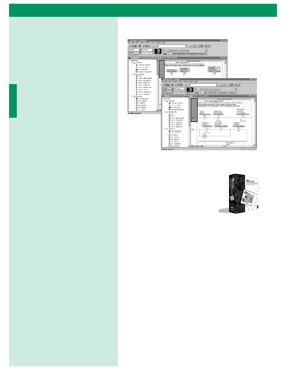
RSLogix 500 Programming Software
The RSLogix 500 ladder logic programming
package helps you maximize performance,
save project development time, and improve
productivity. This product has been
developed to operate on Microsoft’s 32-bit,
Windows
®
95, Windows
®
98, and Windows
NT™ operating systems. Supporting Allen-
Bradley’s MicroLogix families of processors
and SLC 500, RSLogix 500 was the first PLC
programming software to offer unbeatable productivity with an
industry-leading user interface.
Flexible, Easy-to-Use Editors
Flexible program editors let you create application programs without
worrying about getting the syntax correct as you create your program.
A Project Verifier builds a list of errors that you can navigate to make
corrections at your convenience.
Drag-and-drop editing lets you quickly move or copy instructions
from rung to rung within a project, rungs from one subroutine or
project to another, or data table elements from one data file to
another.
Context menus for common software tools are quickly accessible by
clicking the right mouse button on addresses, symbols, instructions,
rungs, or other application objects. This convenience provides you
with all the necessary functionality to accomplish a task within a
single menu.
Programming Software
The following section describes
programming options available for the
MicroLogix 1500 controllers. With
RSLogix 500 Programming Software, you
can create, modify, and monitor
application programs used by the
MicroLogix 1000, MicroLogix 1200 and
SLC Programmable Controller families.
2
MicroLogix 1500 Programmable Controller with Compact I/O for Expansion
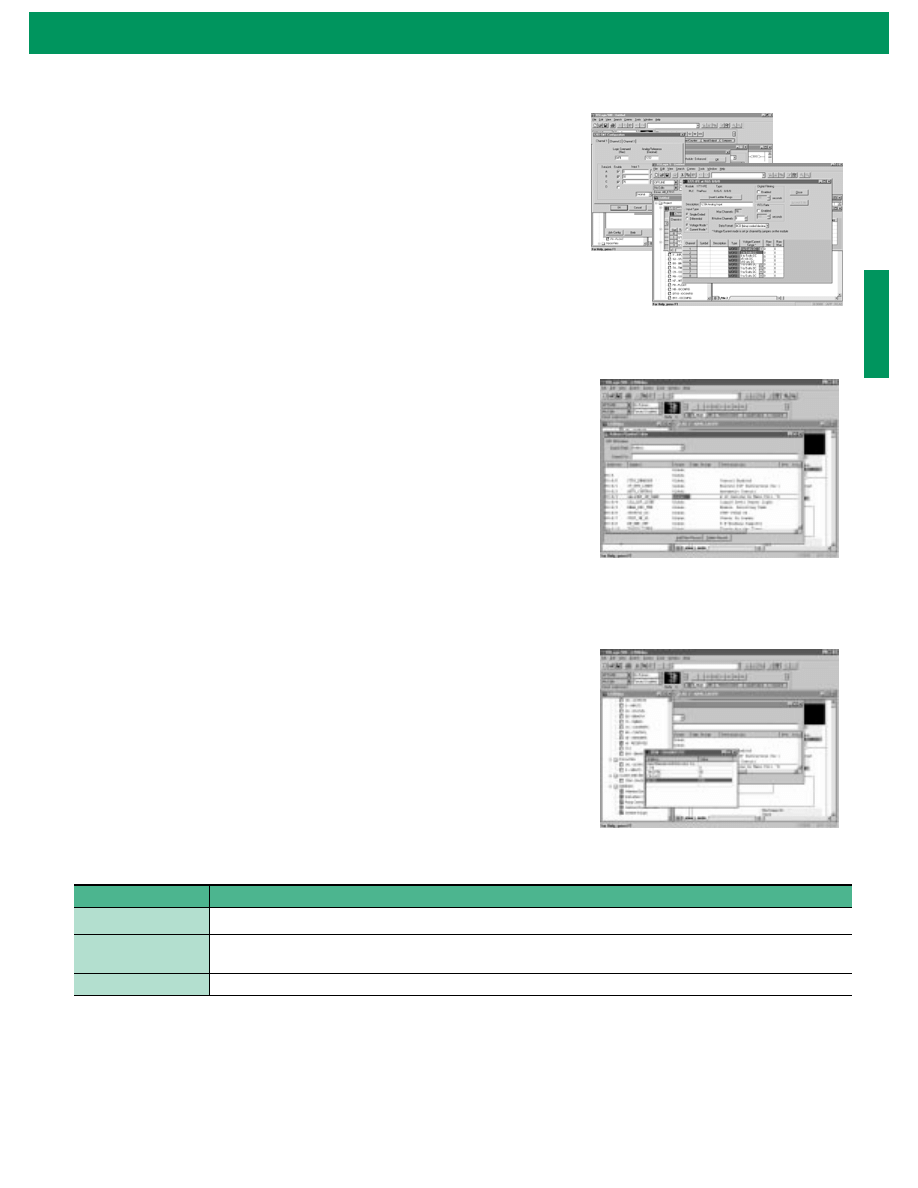
Point-and-Click I/O Configuration
The easy-to-use I/O Configurator lets you click or drag-and-drop a module
from an all-inclusive list to assign it a slot in your configuration. Advanced
configuration, required for specialty and analog modules, is easily accessible.
Convenient forms speed entry of configuration data. An I/O auto configuration
feature is also available.
Powerful Database Editor
Use the Symbol Group Editor to build and classify groups of symbols so that you
can easily select portions of your recorded documentation to be used from
project to project.
Use the Symbol Picker list to easily address instructions in your ladder logic by
clicking addresses or symbols to assign them to your ladder instructions.
Diagnostics and Troubleshooting Tools
Simultaneously examine the status of bits, timers, counters, inputs, and outputs
all in one window with the Custom Data Monitor. Each application project you
create can have its own Custom Data Monitor window.
Easily review status bit settings specific to your application programming
including Scan Time information, Math Register information, Interrupt settings
and more with the tabbed Status displays.
Selection Chart
Catalog Number
Description
9324-RL0300ENE
(1)
(2)
(1) To use RSLogix 500 programming software, your system must be a Pentium 100 MHz or higher, Windows® 95, Windows® 98, or Windows NT™ (v4.0).
(2) Also available in French, German, Italian, Spanish and Portuguese.
RSLogix 500 Programming for the MicroLogix families and SLC 500 on CD-ROM. Includes RSLinx Lite.
9324-RL0100ENE
RSLogix 500 Starter Programming for the MicroLogix families and SLC 500 on CD-ROM. This package is a functionally
limited version of RSLogix 500.
Programming Cables
See page 27 for information on programming cables.
Point-and-Click I/O Configuration
Powerful Database Editor
Diagnostics and Troubleshooting Tool

MicroLogix 1500 Programmable Controller with Compact I/O for Expansion
4
Functional Group Description
Relay-Type (Bit)
The relay-type (bit) instructions monitor and control the status
of bits.
XIC, XIO, OTE, OTL, OTU, OSR, ONS, OSF
Timer and Counter
The timer and counter instructions control operations based on
time or the number of events.
TON, TOF, RTO, CTU, CTD, RES
Compare
The compare instructions compare values by using a specific
compare operation.
EQU, NEQ, LES, LEQ, GRT, GEQ, MEQ, LIM
Math
The math instructions perform arithmetic operations.
ADD, SUB, MUL, DIV, NEG, CLR, SQR, SCL, SCP
Conversion
The conversion instructions multiplex and de-multiplex data
and perform conversions between binary and decimal values.
DCD, ENC, TOD, FRD
Logical
The logical instructions perform bit-wise logical operations on
words.
AND, OR, XOR, NOT
Move
The move instructions modify and move data.
MOV, MVM
File
The file instructions perform operations on multiple data
words.
COP, FLL, BSL, BSR, FFL, FFU, LFL, LFU
Sequencer
Sequencer instructions are used to control automatic
assembly machines that have consistent and repeatable
operations. SQC, SQO, SQL
Program Control
The program flow instructions control the flow of ladder
program execution.
JMP, LBL, JSR, SBR, RET, SUS, TND, MCR, END
Input and Output
The input and output instructions allow you to selectively
update data without waiting for the input and output scans.
IIM, IOM, REF
User Interrupt
The user interrupt instructions allow you to interrupt your
program based on defined events.
STS, INT, UID, UIE, UIF
Process Control
The process control instruction provides closed-loop control.
PID (Proportional/Integral/Derivative)
Communications
The communication instructions read or write data to another
station.
MSG, SVC
High-Speed Counter The high-speed counter instructions configure, control and
monitor the embedded high-speed counters.
HSL, RAC
High-Speed Outputs The high-speed output instructions allow you to control and
monitor the PTO and PWM functions which control the
physical high-speed outputs.
PTO, PWM
ASCII
The ASCII instructions use the communication channel for
receiving or transmitting data and manipulate string data.
ACB, ACL, AHL, ARD, AEX, ACI, AIC, SWP, AWT, AWA, ASC,
ASR
Data Log
(1)
(1) Available with catalog number 1764-LRP
The data log instruction allows you to store records into data
logging memory.
DLG
Programming Instructions
The following table shows the MicroLogix
1500 instruction set listed within their
functional groups.
The MicroLogix 1500’s enhanced
programming instructions feature the new
data logging instruction which enables
you to define controller variables that can
be saved as a record. The elements of each
record can be any mix of integer or double
integer data (catalog number 1764-LRP).
2
MicroLogix 1500 Programmable Controller with Compact I/O for Expansion
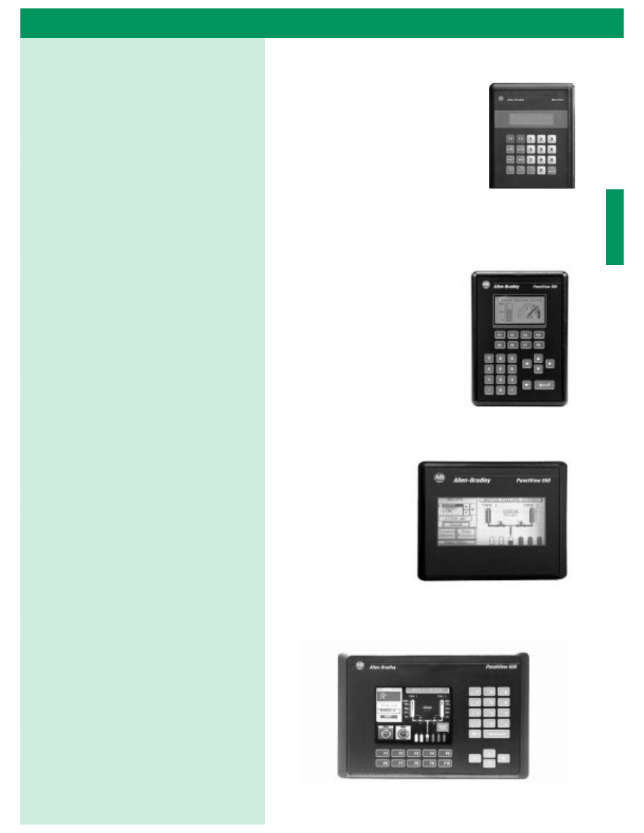
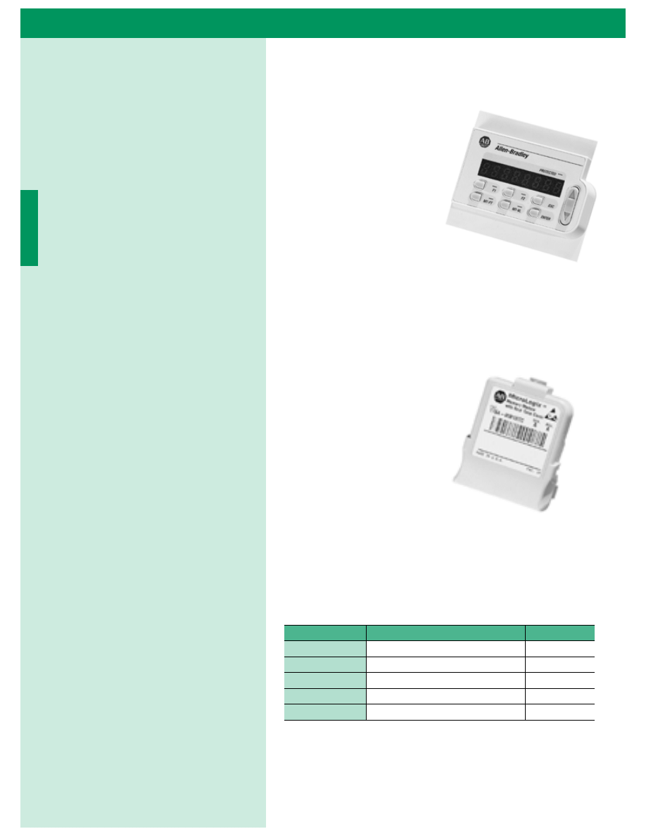
MicroView™ Operator Interface
The MicroView Operator Interface is a
feature-packed, cost-effective operator
interface designed for data monitoring,
data display, data entry, and recipe
download. This device features a 2-line x
16-character display window.
PanelView™ 300, 550 and 600 Operator Interface
Terminals
The PanelView 300, 550
and 600 operator terminals
offer electronic operator
interface capabilities in a
space-saving, flat-panel
design. The result is a
compact package that is
loaded with performance
functionality. These
terminals feature pixel
graphics for enhanced
operator screens.
The PanelView
Standard 300
and 550
interfaces have
monochrome
LCD displays
while the
PanelView 600
has either an
active matrix
thin film
transistor (TFT)
or passive matrix
color display.
Operator Interface Devices
Electronic operator interface devices
provide you with powerful plant floor
control and data monitoring capabilities
for improved productivity. They are easy
to use, rugged and reliable. Operator
interface devices also save valuable panel
space and are designed for easy
modification as your process expands or
changes.
The PanelView
™
products listed are only
a partial offering of the PanelView
Standard (HMI) Human Interface
products. For more information, refer to
the PanelView
™
Standard Operator
Interface Terminals System Overview,
publication 2711-SO001A-US-P.
PanelView 300 (Monochrome)
PanelView 550 Touch Only (Monochrome)
PanelView 600 Keypad (Color)
MicroView Operator Interface
MicroLogix 1500 Programmable Controller with Compact I/O for Expansion
6
Data Access Tool
(1764-DAT)
•
Direct access to 48 bit
elements
•
Direct access to 48 integer
elements
•
Two function keys
•
Display of controller
faults
•
Removal/Insertion under
power
Memory and Real-Time Clock Modules
(1764-MM1, -MM2, -MM1RTC, -MM2RTC, 1764-RTC)
•
Availability allows for
time/date scheduling
applications to be easily
solved.
•
Memory backup and real-
time clock/memory
module
•
User Program and Data
Back-up
•
Program Compare
•
Data File Protection
•
Memory Module Write Protection
•
Removal/Insertion Under Power
Several modules with different levels of functionality are available for
use with the MicroLogix 1500 controller.
Catalog Number
Function
Memory
1764-RTC
Real-Time Clock
Not Applicable
1764-MM1
Memory Module
8K
1764-MM2
Memory Module
16K
1764-MM1RTC
Memory Module and Real-Time Clock
8K
1764-MM2RTC
Memory Module and Real-Time Clock
16K
Accessories
2
MicroLogix 1500 Programmable Controller with Compact I/O for Expansion
Cables
Use the communication cables listed below with the MicroLogix 1500 controllers. Cables come in several lengths and
connector styles to provide connectivity to the MicroLogix family of products.
Catalog Number
Cable Type
Description
1761-CBL-AC00
9-pin D-shell to 9-pin D-shell This 45 cm (17.7 in.) cable is used to connect port 1 of the 1761-NET-AIC to the 9-Pin DTE
port of a personal computer.
1747-CP3
9-pin D-shell to 9-pin D-shell This 3m (9.8 ft) cable is used to connect port 1 of the 1761-NET-AIC to the 9-Pin DTE port of
a personal computer.
1761-CBL-AM00
8-pin DIN to 8-pin DIN
This 45 cm (17.7 in.) cable is used to connect the MicroLogix controller to port 2 of the
1761-NET-AIC
1761-CBL-HM02
8-pin DIN to 8-pin DIN
This 2m (6.56 ft) cable is used to connect the MicroLogix 1500 Programmable Controller to
the HHP or to connect any MicroLogix Programmable Controller to port 2 of the 1761-NET-
AIC
1761-CBL-AP00
9-pin D-shell to 8-pin DIN
This 45cm (17.7 in.) cable is used to connect a MicroLogix controller to port 1 of the
1761-NET-AIC.
1761-CBL-PM02
9-pin D-shell to 8-pin DIN
This 2m (6.56 ft) cable is used to connect the MicroLogix Programmable Controller to an
IBM compatible PC or to connect an IBM compatible PC to port 2 of the 1761-NET-AIC
Compact I/O Expansion Cables
1769-CRR1
This 305 mm (1 ft.) right bank-to-right bank cable is used to add a second bank of I/O modules.
1769-CRR3
This 1 m (3.28 ft.) right bank-to-right bank is used to add a second bank of I/O modules.
1769-CRL1
This 305 mm (1 ft.) right bank-to-left bank is used to add a second bank of I/O modules.
1769-CRL3
This 1 m (3.28 ft.) right bank-to-left bank cable is used to add a second bank of I/O modules.
MicroLogix 1500 Programmable Controller with Compact I/O for Expansion
8
For an introduction to micro PLC’s refer to the MicroMentor™,
Publication 1761-MMB. The MicroMentor book includes
illustrations, sample applications you can put to immediate use, step-
by-step strategies, and worksheets.
Additionally, MicroLogix 1500 user documentation presents
information according to the tasks you perform and the
programming environment you use. Refer to the table below for
information on MicroLogix 1500, 1769 Compact I/O and related
publications.
For assistance selecting the correct MicroLogix Programmable
Controller for your application, see the MicroLogix selector guide on
the back of this publication. If you would like a system overview for
the MicroLogix 1000 or MicroLogix 1200 controllers, refer to the
following table.
To purchase a manual or download a free electronic version, visit us
at
http://www.theautomation bookstore.com
. Or, for fast access to
Bulletin 1761, 1762, and 1764 publications, visit the MicroLogix
Internet site
http://www.ab.com/micrologix
. Electronic versions of
our manuals are available for you to search and download.
See this Document
Publication Number
MicroLogix™ 1500 Programmable Controllers
Installation Instructions
1764-IN001B-ML-P
MicroLogix™ 1500 Programmable Controllers User
Manual
1764-UM001A-US-P
(1)
(1) Manual includes information on 1764-LRP processor and MicroLogix 1500 enhanced functionality.
MicroLogix™ 1200 and MicroLogix™ 1500 Instruction
Set Reference Manual
1762-RM001B-US-P
(1)
Bulletin 1769 Compact™ I/O Analog Input/Output
Modules
1769-1.2
1769 Compact™ Discrete Input/Output Modules
Technical Data
1769-2.1
1769 Compact™ I/O Power Supplies and
Communication Bus Expansion Cables Technical Data
1769-TD001A-US-P
Compact™ I/O Analog Modules User Manual
1769-6.0
AIC+ Advanced Interface Converter and DeviceNet
Interface Installation instructions
1761-5.11
AIC+ Advanced Interface Converter User Manual
1761-6.4
DeviceNet™ Interface User Manual
1761-6.5
DTAM™ Micro Operator Interface Module User Manual 2707-803
MicroView™ Operator Interface Module User Manual
2707-805
DataDisc™ CD-ROM Information Library
1795-CDRS and 1795-
CDRL
See this Document
Publication
Number
MicroLogix™ 1000 System Overview
1761-SO001A-US-P
MicroLogix™ 1200 System Overview
1762-SO001A-US-P
User Documentation
2
MicroLogix 1500 Programmable Controller with Compact I/O for Expansion
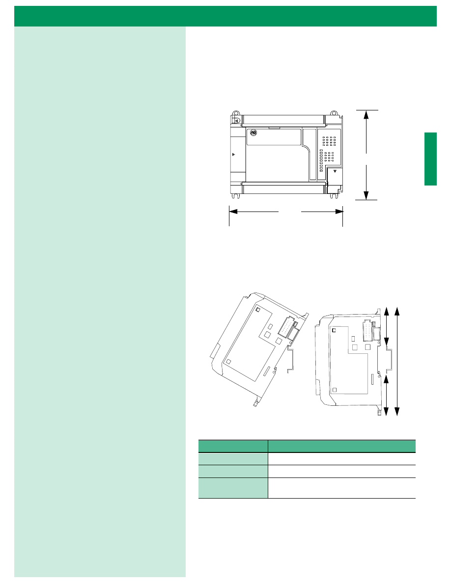
Dimension Drawings
1764-24AWA, -24BWA, -28BXB
MicroLogix 1500 DIN Rail Dimensions
Dimension
Height
A
138 mm (5.43 in.)
B
47.6 mm (1.875 in.)
C
47.6 mm (1.875 in) DIN latch closed
54.7 mm (2.16 in.) DIN latch open
138 (5.43)
168
(6.62)
Front View
B
C
A
Side View
Dimensions
0
MicroLogix 1500 Programmable Controller with Compact I/O for Expansion
Compact I/O Modular Input/Output System
Compact I/O Expansion Power Supply and End Caps
132
(5.197)
122.6±0.2
(4.826±0.008)
35
(1.38)
28.5
(1.12)
For more than 2 modules: (number of modules - 1) x 35 mm (1.38in.)
Refer to host controller documentation for this dimension.
NOTE: All dimensions are in
mm (inches). Hole spacing
tolerance: ±0.4 mm (0.016 in.)
H
o
st Contr
o
ll
er
C
o
mpact I/O
C
o
mpact I/O
C
o
mpact I/O
End Cap
132
(5.197)
122.6±0.2
(4.826±0.008)
70
(2.76)
28.5
(1.12)
35
(1.38)
35
(1.38)
40
(1.58)
Power
S
upply
Right End Cap
Compact I/
O
Compact I/
O
NOTE: All dimensions are in
mm (inches). Hole spacing
tolerance: ±0.4 mm (0.016 in.)
For more than 2 modules: (number of modules - 1) x 35 mm (1.38in.)
Left End Cap
NOTE: Compact I/O expansion
cables have the same
dimensions as the end caps.

3
MicroLogix 1500 Programmable Controller with Compact I/O for Expansion
MicroLogix 1500 Master Parts List
Catalog Number
Description
Processor: (required, must be interfaced to a base unit, see below)
1764-LSP
Greater than 7K user memory
1764-LRP
12K user memory/RS-232 isolated Comm port/data logging
Base: (one of the following bases is required, for each processor)
1764-24AWA
AC Powered, 12 AC IN / 12 Relay Out
1764-24BWA
AC Powered, 12 DC IN / 12 Relay Out
1764-28BXB
24V DC Powered, 16 DC IN / 6 Relay and 6 DC FET Out
Accessories:
1764-DAT
Data Access Tool
1764-RTC
Real-Time Clock
1764-MM1
Memory Module (8K)
1764-MM2
Memory Module (16K)
1764-MM1RTC
Memory Modules with Real-Time Clock (8K)
1764-MM2RTC
Memory Modules with Real-Time Clock (16K)
Expansion I/O Modules: (See page 10 for part numbers and descriptions.)
Expansion Power Supplies and Cables: (See page 14 for part numbers and descriptions.)
Training Materials:
1764-START1500E
MicroLogix 1500 RSLogix Starter Pak includes: 1764-LSP processor; 1764-24BWA base unit; 9323-
RL0100ENE (RSLogix Starter Programming Software); 1761-CBL-PM02 PC-to-controller cable; 1764-
MM1RTC memory module and real-time clock; user documentation
1796-MICRO151 (Series B)
MicroLogix 1500 Integrated Demonstration Unit includes: 1764-28BXB base unit; 1764-LSP processor
unit; 1769-IF4 Analog Input Module; 1769-OF2 Analog Output Module;1761-NET-AIC DH-485 Interface
Module; 1761-NET-DNI DeviceNet Interface Module; quadrature encoder; 4 selector switches; 8
illuminated pushbuttons; 1 potentiometer; 1 analog meter; 1 frequency meter
1796-SIM1500
MicroLogix 1500 Input Simulator. For use with 1764-24BWA and 1764-28BXB base units.
MicroLogix 1500 Replacement Parts:
1764-RPLTRM1
Electrostatic Discharge Sticker
1764-RPLTDR1
Terminal Cover Doors (2 doors per package)
1764-RPLCDR1
Processor Unit Door
1764-RPLDR
Complete Door Kit (includes all doors for 1 controller)
1764-RPLTB1
Replacement Terminal Block — 17-pt for 1764-24AWA and 1764-24BWA inputs
Publication 1764-SO001B-EN-P — May 2000
© 2000 Rockwell International Corporation. All rights reserved. Printed in USA.
Supersedes Publication 1764-SO001A-US-P — December 1999
MicroLogix 1000
MicroLogix 1200
MicroLogix 1500
1761
1762
1764-LSP
1764-LRP
Memory
Up to 1K
•
Up to 6K
•
Up to 7K
•
Up to 12K
•
EEPROM Back-up
•
•
Battery Back-up
•
•
Back-up Memory Module
•
•
•
I/O
Up to 32
•
Up to 88 (using 1762 I/O)
•
Up to 156 (using 1769 I/O)
•
•
Added Functionality
Analog (Embedded)
•
Analog (Expansion)
•
•
•
Trim Potentiometers
2
2
2
PID
•
•
•
High Speed Counters
1
1
2
2
Real Time Clock
•
•
•
Motion Capabilities (Pulse Width
1
*
2
2
Modulated and Pulse Train Outputs)
Data Access Tool
•
•
Data Logging (50k bytes)
•
Programming Software
Windows - RSLogix 500
•
•
•
•
DOS - A.I. 500
•
Communications
RS-232 Ports
1
1
1
2
DeviceNet (1761-NET-DNI)
•
•
•
•
DH485 (1761-NET-AIC)
•
•
•
•
SCADA RTU - DF1 Half-Duplex Slave
•
•
•
•
SCADA RTU - Modbus RTU Slave
•
•
•
ASCII - Write only
•
ASCII - Read/Write
•
•
Operating Power
120/240V ac
•
•
•
•
24V dc
•
•
*
•
•
UL, CSA or C-UL, CE, Class I Div.2
•
•
•
•
* Available in late 2000. Contact your Allen-Bradley sales representative or authorized distributor for availability.
Compact, DataHighway PLus, MicroView, MicroLogix, RSLogix, RSLinx and PanelView are trademarks of Rockwell Automation. DeviceNet is a trademark of Open DeviceNet
Vendor Association. Ethernet is a registered trademark of Digital Equipment Corporation, Intel and Xerox Corporation. ControlNet is a trademark of ControlNet International, Ltd.
Windows 95 and Windows 98 are registered trademarks of Microsoft Corporation. Windows NT is a trademark of Microsoft Corporation. Modbus is a trademark of Modicon, Inc.
Document Outline
- Rockwell Automation Catalogs on CD
- 1764-SO001B-EN-P, MicroLogix 1500 Programmable Controller with Compact I/) for Expansion System Overview
- Take Control
- Table of Contents
- MicroLogix 1500 System
- Expansion I/O Modules
- Expansion Power Supplies and Cables
- Communication Choices
- Network Interface Devices
- High-Speed Functions
- Programming Software
- Programming Instructions
- Operator Interface Devices
- Accessories
- User Documentation
- Dimensions
- MicroLogix 1500 Master Parts List
- Back Cover
Wyszukiwarka
Podobne podstrony:
Budzik Versa wielkość karty kredytowej instrukcja EN
G2 4 PW EN wn Rys 01
Manual Acer TravelMate 2430 US EN
Ćwiczenie 01 EN DI
eci en
BVSOI 3 001 E en
A Biegus projektowanie konctrukcji stalowych wg PN EN 1993 1 1 cz 1
Flavon Active dopping EN
5817 PN EN ISO IV 2007
Pisownia ę ą en em om
NS2 lab 4 4 7 en Configure Cisco IOS IPSec using Pre Shared Keys
PN EN 1990 2004 AC Podstawy projektowania konstrukcji poprawka
EN w9 wspolpraca z siecia
EN SUPERRAIL
overview simatic controllers 04 2007 en plc
1510478 8000SRM0988 (06 2005) UK EN
HGDS EN
więcej podobnych podstron