
CEN/TC250/SC1/
N391
EUROPEAN STANDARD
NORME EUROPÉENNE
EUROPÄISCHE NORM
Draft prEN 1991-1-7
English version
prEN 1991-1-7
EUROCODE 1 - Actions on structures
Part 1-7: General Actions - Accidental actions
FINAL PROJECT TEAM DRAFT (STAGE 34)
5
th
March 2003
CEN
European Committee for Standardization
Comité Européen de Normalisation
Europäisches Komitee für Normung
Central Secretariat : rue de Stassart 36, B-1050 Brussels
© CEN 1994 Copyright reserved to all CEN members
Ref.N° .......

page 2
Draft prEN 1991-1-7:2003
Contents
Page
Links between Eurocodes and harmonised technical specifications (ENs and ETAs) for products7
SECTION 2 CLASSIFICATION OF ACTIONS ..............................................12
SECTION 3 DESIGN SITUATIONS..............................................................13
FIGURE 3.1: ACCIDENTAL DESIGN SITUATIONS ....................................15

page
3
Draft prEN 1991-1-7:2003
4.5.1.1 Introduction............................................................................................................................26
4.5.1.2 Classification of structures.....................................................................................................26
4.5.1.3 Accidental Design Situations in relation to the classes of structure.......................................27
4.5.1.4 Class A structures ..................................................................................................................27
4.5.1.5 Class B structures...................................................................................................................28
4.5.2 Structures located in areas beyond track ends...........................................................................29
4.6
SECTION 5 INTERNAL EXPLOSIONS.......................................................34
A1 SCOPE AND FIELD OF APPLICATION .................................................37
A6.2 LOAD-BEARING WALL CONSTRUCTION.........................................42
GUIDANCE FOR RISK ANALYSIS...............................................................45
INTERNAL EXPLOSIONS ............................................................................65
D1 DUST EXPLOSIONS IN ROOMS AND SILOS ......................................65

page 4
Draft prEN 1991-1-7:2003
D2 DUST EXPLOSIONS IN ENERGY DUCTS............................................66
D3 GAS AND VAPOUR/AIR EXPLOSIONS IN ROOMS, CLOSED
SEWAGE BASSINS ......................................................................................66
D4 NATURAL GAS EXPLOSIONS .............................................................67
D5 GAS AND VAPOUR/AIR EXPLOSIONS IN ENERGY DUCTS..............68
D6 EXPLOSIONS IN ROAD AND RAIL TUNNELS ....................................68

page
5
Draft prEN 1991-1-7:2003
Foreword
This European document (EN 1991-1-7:2003) has been prepared on behalf of Technical
Committee CEN/TC250 “Structural Eurocodes”, the Secretariat of which is held by BSI.
This document is currently submittted to the formal vote.
This document will supersede ENV 1991-2-7:1998.
Background of the Eurocode programme
In 1975, the Commission of the European Community decided on an action programme in the field of
construction, based on article 95 of the Treaty. The objective of the programme was the elimination of
technical obstacles to trade and the harmonisation of technical specifications.
Within this action programme, the Commission took the initiative to establish a set of harmonised
technical rules for the design of construction works which, in a first stage, would serve as an alternative
to the national rules in force in the Member States and, ultimately, would replace them.
For fifteen years, the Commission, with the help of a Steering Committee with Representatives of
Member States, conducted the development of the Eurocodes programme, which led to the first
generation of European codes in the 1980s.
In 1989, the Commission and the Member States of the EU and EFTA decided, on the basis of an
agreement
between the Commission and CEN, to transfer the preparation and the publication of the
Eurocodes to CEN through a series of Mandates, in order to provide them with a future status of
European Standard (EN). This links de facto the Eurocodes with the provisions of all the Council’s
Directives and/or Commission’s Decisions dealing with European standards (e.g. the Council Directive
89/106/EEC on construction products – CPD - and Council Directives 93/37/EEC, 92/50/EEC and
89/440/EEC on public works and services and equivalent EFTA Directives initiated in pursuit of
setting up the internal market).
The Structural Eurocode programme comprises the following standards generally consisting of a
number of Parts:
EN 1990
Eurocode
Basis of Structural Design
EN 1991
Eurocode 1:
Actions on structures
EN 1992
Eurocode 2:
Design of concrete structures
EN 1993
Eurocode 3:
Design of steel structures
EN 1994
Eurocode 4:
Design of composite steel and concrete structures
EN 1995
Eurocode 5:
Design of timber structures
EN 1996
Eurocode 6:
Design of masonry structures
EN 1997
Eurocode 7:
Geotechnical design
EN 1998
Eurocode 8:
Design of structures for earthquake resistance
1
Agreement between the Commission of the European Communities and the European Committee for
Standardisation (CEN) concerning the work on EUROCODES for the design of building and civil engineering works
(BC/CEN/03/89).

page 6
Draft prEN 1991-1-7:2003
EN 1999
Eurocode 9:
Design of aluminium structures
Eurocode standards recognise the responsibility of regulatory authorities in each Member
State and have safeguarded their right to determine values related to regulatory safety
matters at national level where these continue to vary from State to State.
Status and field of application of Eurocodes
The Member States of the EU and EFTA recognise that Eurocodes serve as reference documents for
the following purposes :
– as a means to prove compliance of building and civil engineering works with the essential
requirements of Council Directive 89/106/EEC, particularly Essential Requirement N°1 –
Mechanical resistance and stability – and Essential Requirement N°2 – Safety in case of
fire ;
– as a basis for specifying contracts for construction works and related engineering services ;
– as a framework for drawing up harmonised technical specifications for construction products
(ENs and ETAs)
The Eurocodes, as far as they concern the construction works themselves, have a direct relationship
with the Interpretative Documents
referred to in Article 12 of the CPD, although they are of a different
nature from harmonised product standards
. Therefore, technical aspects arising from the Eurocodes
work need to be adequately considered by CEN Technical Committees and/or EOTA Working Groups
working on product standards with a view to achieving a full compatibility of these technical
specifications with the Eurocodes.
The Eurocode standards provide common structural design rules for everyday use for
the design of whole structures and component products of both a traditional and an
innovative nature. Unusual forms of construction or design conditions are not
specifically covered and additional expert consideration will be required by the
designer in such cases.
National Standards implementing Eurocodes
The National Standards implementing Eurocodes will comprise the full text of the Eurocode (including
any annexes), as published by CEN, which may be preceded by a National title page and National
foreword, and may be followed by a National annex (informative).
The National Annex (informative) may only contain information on those parameters which are left
open in the Eurocode for national choice, known as Nationally Determined Parameters, to be used for
the design of buildings and civil engineering works to be constructed in the country concerned, i.e.:
–values and/or classes where alternatives are given in the Eurocode;
–values to be used where a symbol only is given in the Eurocode,
2
According to Art. 3.3 of the CPD, the essential requirements (ERs) shall be given concrete form in interpretative
documents for the creation of the necessary links between the essential requirements and the mandates for hENs
and ETAGs/ETAs.
3
According to Art. 12 of the CPD the interpretative documents shall :
a)give concrete form to the essential requirements by harmonising the terminology and the technical bases and indicating
classes or levels for each requirement where necessary ;
b)indicate methods of correlating these classes or levels of requirement with the technical specifications, e.g. methods of
calculation and of proof, technical rules for project design, etc. ;
c)serve as a reference for the establishment of harmonised standards and guidelines for European technical approvals.
The Eurocodes, de facto, play a similar role in the field of the ER 1 and a part of ER 2.

page
7
Draft prEN 1991-1-7:2003
–country specific data (geographical, climatic, etc).e.g. snow map,
– procedure to be used where alternative procedures are given in the Eurocode,
It may also contain;
- decisions on the application of informative annexes;
–references to non-contradictory complementary information to assist the user to apply the
Eurocode.
Links between Eurocodes and harmonised technical specifications (ENs and
ETAs) for products
There is a need for consistency between the harmonised technical specifications for construction
products and the technical rules for works
. Furthermore, all the information accompanying the CE
Marking of the construction products which refer to Eurocodes shall clearly mention which Nationally
Determined Parameters have been taken into account.
Additional information specific to EN 1991-1-7
EN 1991-1-7 describes Principles and Application rules for the assessment of accidental
actions on buildings and bridges, including the following aspects :
-- Impact forces from vehicles, rail traffic, ships and helicopters
-- Internal explosions
-- Consequences of local failure
EN 1991-1-7 is intended for use by:
clients (e.g. for the formulation of their specific requirements on safety levels),
designers,
constructors and
relevant authorities.
EN 1991-1-7 is intended to be used with EN 1990, the other Parts of EN 1991 and EN 1992 – 1999 for
the design of structures.
National annex
This standard gives alternative procedures, values and recommendations for classes with notes
indicating where national choices may have to be made. Therefore the National Standard implementing
EN 1991-1-7 should have a National Annex containing all Nationally Determined Parameters to be
used for the design of buildings and civil engineering works to be constructed in the relevant country.
4
see Art.3.3 and Art.12 of the CPD, as well as clauses 4.2, 4.3.1, 4.3.2 and 5.2 of ID 1.

page 8
Draft prEN 1991-1-7:2003
The National choice is allowed in prEN 1991-1-7 through clauses
:
Clause
Item
3.1(4)
Probability of accidental actions
3.2(1)P
Level of risk
3.3(1)P
Notional accidental actions
3.3(1)P
Choice of strategies
3.4(1)
Consequences classes
4.3.1(1)
Values of vehicle impact forces
4.3.1(5)
Application of impact forces from lorries
4.3.2(2)
Value of probability factor
4.4(1)
Value of impact forces from forklift trucks
4.5.1.2(1)P
Consequences classes
4.5.1.2(1)P
Classification of temporary works
4.5.1.4(1)
Impact forces from derailed traffic
4.5.1.4(2)
Reduction of impact forces
4.5.1.4(5)
Impact forces for speeds greater than 120km/h
4.5.1.5(1)
Requirements for Class B structures
4.5.2(1)
Areas beyond track ends
4.5.2(4)
Impact forces on end walls
4.6.2(1)
Values of frontal and lateral forces from ships
4.6.2(6)
Impact forces on bridge decks from ships
4.6.3(1)
Dynamic impact forces from ships
EN 1991-1-7 indicates through NOTES where additional decisions for the particular
project may have been taken, directly or through the National Annex, for the
following clauses:
Clause
Item
4.5.1.4(5)
Impact forces from rail traffic greater
than 120 km/h
4.5.2(4)
Impact forces on end walls
5
It is proposed to add to each clause of the list what will be allowed for choice: value, procedures, classes.

page
9
Draft prEN 1991-1-7:2003
Section 1 General
1.1 Scope
(1) EN 1991-1-7 provides rules for safeguarding buildings and other civil engineering
works against accidental actions. For buildings, EN 1991-1-7 also provides strategies
to limit the consequences of localised failure caused by an unspecified accidental
event. The recommended strategies for accidental actions range from the provision of
measures to prevent or reduce the accidental action to that of designing the structure
to sustain the action.
In this context specific rules are given for accidental actions caused by impact and
internal explosions. Localised failure of a building structure, however, may result
from a wide range of events that could possibly affect the building during its life-
span. Such events may not necessarily be anticipated by the designer.
This Part does not specifically deal with accidental actions caused by external
explosions, warfare and terrorist activities, or the residual stability of buildings or
other civil engineering works damaged by seismic action or fire etc. However, for
buildings, adoption of the robustness strategies given in Annex A for safeguarding
against the consequences of localised failure should ensure that the extent of the
collapse of a building, if any, will not be disproportionate to the cause of the localised
failure.
This Part does not apply to dust explosions in silos (See EN1991 Part 4), nor to
impact from traffic travelling on the bridge deck or to structures designed to accept
ship impact in normal operating conditions eg. quay walls and breasting dolphins.
(2) The following subjects are dealt with in this European standard:
-
definitions and symbols (section 1);
-
classification of actions (section 2);
-
design situations;
-
impact
-
explosions
-
robustness of buildings – design for consequences of localised failure from an unspecified
cause (informative annex A);
-
guidance for risk analysis (informative annex B);
-
advanced impact design (informative annex C);
-
internal explosions (informative annex D).

page 10
Draft prEN 1991-1-7:2003
1.2 Normative references
This European standard incorporates by dated or undated reference provisions from other
publications. These normative references are cited at the appropriate places in the text
and the publications are listed hereafter. For dated references, subsequent amendments
to, or revisions of, any of these publications apply to this European standard only when
incorporated in it by amendment or revision. For undated references, the latest edition of
the publication referred to applies (including amendments).
NOTE : The Eurocodes were published as European Prestandards. The following
European Standards which are published or in preparation are cited in normative clauses
or in NOTES to normative clauses.
EN 1990
Eurocode : Basis of Structural Design
EN 1991-1-1
Eurocode 1: Actions on structures Part 1-1: Densities, self-
weight, imposed loads for buildings.
EN 1991-1-6
Eurocode 1: Actions on structures Part 1-6: Actions during
execution
EN 1991-2
Eurocode 1: Actions on structures Part 2: Traffic loads on
bridges
EN 1991-4
Eurocode 1 : Actions on structures Part 4 :Actions in silos and
tanks
EN 1992 Eurocode 2: Design of concrete structures
EN 1993 Eurocode 3: Design of steel structures
EN 1994 Eurocode 4: Design of composite steel and concrete structures
EN 1995 Eurocode 5: Design of timber structures
EN 1996 Eurocode 6: Design of masonry structures
EN 1997
Eurocode 7: Geotechnical design
EN 1998
Eurocode 8: Design of structures for earthquake resistance
EN 1999
Eurocode 9: Design of aluminium structures
1.3 Assumptions
(1)P The general assumptions given in EN 1990, clause 1.3 shall apply to this Part of EN 1991.
1.4 Distinction between principles and application rules
(1) P The rules given in EN 1990, clause 1.4 shall apply to this Part of EN 1991.
1.5 Terms and definitions
For the purposes of this European standard, general definitions are provided in EN 1990 clause 1.5.
Additional definitions specific to this Part are given below.

page
11
Draft prEN 1991-1-7:2003
burning velocity
rate of flame propagation relative to the velocity of the unburned dust, gas
or vapour that is ahead of it
deflagration
propagation of a combustion zone at a velocity that is less than the speed
of sound in the unreacted medium
detonation
propagation of a combustion zone at a velocity that is greater than the
speed of sound in the unreacted medium
flame speed
speed of a flame front relative to a fixed reference point
flammable limits
minimum and maximum concentrations of a combustible material, in a
homogeneous mixture with a gaseous oxidizer that will propagate a flame
venting panel
non-structural part of the enclosure (wall, floor, ceiling) with limited
resistance that is intended to releave the developing pressure from
deflagration in order to reduce pressure on structural parts of the building.
robustness
the ability of a structure to withstand events like fire, explosions, impact or
the consequences of human error, without being damaged to an extent
disproportionate to the original cause.
1.6 Symbols
For the purpose of this European standard, the following symbols apply (see also EN 1990).
K
G
deflagration index of a gas cloud
K
St
deflagration index of a dust cloud
P
max
maximum pressure developed in a contained deflagration of an optimum mixture
P
red
reduced pressure developed in vented enclosure during a vented deflagration
P
stat
static activation pressure that activates a vent closure when the pressure is increased
slowly

page 12
Draft prEN 1991-1-7:2003
Section 2
Classification of actions
(1)P For the assessment of accidental actions on the structure, the Principles and Application Rules in
EN 1990 shall be taken into account. See also Table 2.1
Table 2.1 Clauses in EN 1990 specifically addressing accidental actions.
Section
Clause
Terms and definitions
1.5.2.5, 1.5.3.5, 1.5.3.15,
Symbols
1.6
Basic requirements
2.1 (5)
Design situations
3.2(2)P
Classifications of actions
4.1.1(1)P, 4.1.1(2), 4.1.1(8)
Other representative values of variable actions
4.1.3(1)P
Combination of actions for accidental design
situations
6.4.3.3
Design values for actions in the accidental and
seismic design situations
A1.3.2
(2)P Actions within the scope of this Part of EN1991 shall be classified as accidental actions in
accordance with EN 1990 clause 4.11.

page
13
Draft prEN 1991-1-7:2003
Section 3 Design situations
3.1 General
(1) This Section concerns the accidental design situations that need to be considered
in order to ensure that there shall be a reasonable probability that the damage to the
structure from an exceptional cause will not be considered disproportionate to the
original cause.
(2) Accidental design situations are classified in EN 1990, 3.2.
These may include:
-
events relating to accidental actions (eg explosions and impact).
-
the occurrence of localised failure from an unspecified cause.
NOTE 1: These situations are illustrated in Figure 3.1.
(3) The events to be taken into account may be given in the National Annex, or
agreed for an individual project with Client and the relevant authority. The selected
design situation shall be sufficiently severe and varied so as to encompass a low but
reasonable probability of occurrence.
(4) The representative value of an accidental action should be chosen such that for
medium consequences there is an assessed probability less than ‘p’
per year that this
action, or one of higher magnitude, will occur on the structure.
NOTE 1:The value of ‘’p’ shall be given in the National Annex . The recommended value is
1x10
.-4.
NOTE 2. A severe possible consequence requires the consideration of extensive hazard scenarios,
while less severe consequences allow less extensive hazard scenarios. Because the probability of
occurrence of an accidental action and the probability distribution of its magnitude need to be
determined from statistics and risk analysis procedures, nominal design values are commonly
adopted in practice. Consequences may be assessed in terms of injury and death to people,
unacceptable change to the environment or large economic losses for the society. See Annex B.
3.2 Accidental Design Situations due to Accidental Actions
(1)P Accidental actions shall be accounted for, when specified, in the design of a
structure depending on:
–
the provisions take for preventing or reducing the dangers involved,
–
the probability of occurrence of the initiating event;
–
the consequences of damage to and failure of
the structure;
–
the level of acceptable risk
NOTE 1: In practice, the occurrence and consequences of accidental actions can be associated
with a certain risk level. If this level cannot be accepted, additional measures are necessary. A
zero risk level, however, is unlikely to be reached and in most cases it is necessary to accept a
certain level of residual risk. This final risk level will be determined by the cost of safety

page 14
Draft prEN 1991-1-7:2003
measures weighed against the perceived public reaction to the damage resulting from the
accidental action, together with consideration of the economic consequences and the potential
number of casualties involved. The risk should also be based on a comparison with risks
generally accepted by society in comparable situations.
NOTE 2. Suitable risk levels may be given in the National Annex as non contridictory,
complementary information.

page
15
Draft prEN 1991-1-7:2003
ACCIDENTAL DESIGN SITUATIONS
(To avoid disproportionate damage to the structure from an accidental cause)
LOCALISED FAILURE
ACCIDENTAL ACTIONS
eg explosions and impact
STRATEGIES
STRATEGIES
ENHANCED
REDUNDANCY
KEY ELEMENT
eg alternative load paths DESIGNED TO SUSTAIN
NOTIONAL ACCIDENTAL
PREVENTING OR
DESIGN STRUCTURE
ACTION A
d
REDUCING THE
TO SUSTAIN THE ACTION
ACTION
eg protection measures
PRESCRIPTIVE RULES
eg integrity & ductility
Figure 3.1: Accidental Design Situations

page 16
Draft prEN 1991-1-7:2003
(2) Localised damage due to accidental actions may be acceptable, provided that it will
not endanger the structure and that the overall load-bearing capacity is maintained during
an appropriate length of time to allow necessary emergency measures to be taken.
(3) In the case of building structures such emergency measures may involve the safe
evacuation of persons from the premises and its surroundings. In the case of bridge
structures the survival period may be dependent on the period required to attend to
casualties or to close the road or rail service.
(4) Measures to control the risk of accidental actions may include, as appropriate, one or
more of the following strategies:
–
preventing the action from occurring (eg. in the case of bridges, by providing
adequate clearances between the vehicles and the structure) or reducing to a
reasonable level the probability and/or magnitude of the action by applying the
principles of capacity design (eg. providing sacrificial venting components with a low
mass and strength to reduce the effect of explosions);
–
protecting the structure against the effects of an action by reducing the actual loads on
the structure (e.g. protective bollards or safety barriers) ;
NOTE 1. The effect of preventing actions may be limited; it is dependent upon factors which, over the life
span of the structure, are commonly outside the control of the structural design process. Preventive
measures often involves inspection and maintenance during the life of the structure.
- ensuring that the structure has sufficiently robustness by adopting one or more of the
following approaches;
i)
by designing certain key components of the structure on which its stability depends
to be of enhanced strength so as to raise the probability of their survival following
an accidental action.
ii)
by designing structural members to have sufficient ductility capable of absorbing
significant strain energy without rupture.
NOTE 2:
Annexes A and C, together with EN1992-1-1 to EN1999-1-1, refer.
iii)
by incorporating sufficient redundancy in the structure so as to facilitate the
transfer of actions to alternative load paths following an accidental event.
(5)P The accidental actions shall be considered to act simultaneously in combination
with other permanent and variable actions as given in
EN 1990, 6.4.3.3.
NOTE 1: For values of
ψ, see Table A1.1 in Annex A of EN 1990.

page
17
Draft prEN 1991-1-7:2003
(6)P Where more onerous results are obtained by the omission of variable actions in
whole, or in part, this should be taken into account. Consideration shall also be given to
the safety of the structure immediately following the occurrence of the accidental event.
NOTE 1: This may include the consideration of progressive collapse. See Annex A.
3.3 Accidental Design situations – Consequences of Localised Failure
(1)P Consideration shall also be given to minimising the potential damage to the structure
arising from an unspecified cause, taking into account its use and exposure, by adopting
one or more of the following strategies.
-
designing in such a way that neither the whole structure nor a significant part of it
will collapse if a local failure (e.g. single element failure or damage) occurs;
–
designing key elements, on which the structure is particularly reliant, to sustain a
notional accidental action A
d
;
NOTE 1: The National Annex may give the design value A
d.
Recommended values are given in
Annex A.
- applying prescriptive design/detailing rules that provide an acceptably robust
structure (e.g. three-dimensional tying for additional integrity, or minimum level of
ductility of structural elements subject to impact);
NOTE 2. This is likely to ensure that the structure has sufficient robustness regardless of whether
a specific accidental action can be identified for the structure.
NOTE 3: The National Annex may state which of the strategies given in 3.3(1)P shall be
considered for various structures. Recommendations relating to the use of the strategies
for buildings are included in Annex A.
3.4 Strategies to be considered in regard to Accidental Design Situations.
(1) Consequences classes may be defined as follows:
–
Consequences class 1
Low;
–
Consequences class 2
Medium;
–
Consequences class 3
High.
NOTE 1: See also Annex B of EN 1990.
For facilitating the design of certain Class of structures it might be appropriate to treat
some parts of the structure as belonging to a different class from overall structure. This

page 18
Draft prEN 1991-1-7:2003
might be the case for parts that are structurally separated and differ in exposure and
consequences.
NOTE 2: The effect of preventive and/or protective measures is that the probability of damage to the
structure is removed or reduced. For design purposes this can sometimes be taken into consideration by
assigning the structure to a lower category class. In other cases a reduction of forces on the structure may
be more appropriate.
NOTE 3: The National Annex may provide a classification of consequence classes according to a
categorisation of structures and also the means of adopting the design approaches. A recommended
classification of consequence classes relating to buildings is provided in Annex A.
(2) The different consequences classes may be considered in the following manner:
–
Class 1: no specific consideration is necessary with regard to accidental actions
except to ensure that the robustness and stability rules given in EN 1991 to EN1999,
as applicable, are adhered to;
–
Class 2 structure. depending upon the specific circumstances of the structure, a
simplified analysis by static equivalent action models may be adopted or prescriptive
design/detailing rules may be applied;
–
Class 3: an examination of the specific case should be carried out to determine the level of
reliability required and the depth of structural analyses. This may necessitate a risk analysis
and use of refined methods such as dynamic analyses, non-linear models and load structure
interaction, if considered appropriate.
NOTE 1: The National annex may give, as non conflicting, complementary information, appropriate design
approach classes for different consequence classes of structure.
NOTE 2: In exceptional circumstances the complete collapse of the structure due to an accidental action
may be the preferred option.

page
19
Draft prEN 1991-1-7:2003
Section 4 Impact
4.1 Field of application
(1) This section defines actions due to impact for:
- collisions from vehicles (excluding collisions on lightweight structures);
–
collisions from fork lift trucks;
–
collisions from trains;
–
collisions from ships;
–
the hard landing of helicopters on roofs.
NOTE:
(2) Buildings to be considered are parking garages, buildings in which vehicles or
fork lift trucks are driven and buildings that are located in the vicinity of either
road or railway traffic.
(3) For bridges the actions due to impact to be considered depends upon the
type of traffic under the bridge and the consequences of the impact. In the case
of footbridges, gantries, lighting columns etc., the horizontal static equivalent
design forces may be given as non conflicting, complementary information in the
National Annex
(4) Actions due to impact from helicopters need to be considered only for those
buildings where the roof contains a designated landing pad.
4.2
Representation of actions
(1) P Actions due to impact shall be considered as free actions. The areas where
actions due to impact need to be considered shall be specified individually
depending on the cause.
(2)
In general, the impact process is determined by the impact velocity of the
impacting object and the mass distribution, deformation behaviour, damping
characteristics of both the impacting object and the structure. To find the forces
at the interface, the interaction between the impacting object and the structure
should be considered.
(3)
When defining the material properties of the impacting body and of the
structure, upper or lower characteristic values should be used, where relevant ;
strain rate effects should be taken into account, when appropriate.

page 20
Draft prEN 1991-1-7:2003
(4) For structural design purposes the actions due to impact may be represented
by an equivalent static force giving the equivalent action effects in the structure.
This simplified model may be used for the verification of static equilibrium or for
strength verifications, depending on the protection aim.
(5) For structures which are designed to absorb impact energy by elastic-plastic
deformations of members (so called soft impact), the equivalent static loads may
be determined by considering both plastic strength and deformation capacity of
such members.
Note: for further information see Annex C
(6) For structures for which the energy is mainly dissipated by the impacting body
(so called hard impact), the dynamic or equivalent static forces may
conservatively be taken from clauses 4.3 to 4.7.
Note: for information on design values for masses and velocities of colliding objects as a basis for dynamic
analysis: see Annex C.
4.3 Accidental actions caused by road vehicles
4.3.1 Impact on supporting substructures
(1) In the case of hard impact, design values for the equivalent static actions due
to impact on the supporting substructure (e.g. columns and walls under
bridges) in the vicinity of various types of roads may be obtained from Table
4.3.1.
NOTE 1: For impact from traffic on bridges, reference is made to EN 1991-2.

page
21
Draft prEN 1991-1-7:2003
Table 4.3.1: Horizontal static equivalent design forces due to impact on members
supporting structures over or near roadways.
Type of traffic under the bridge
Type of vehicle
Force F
d,x
[kN]
Force F
d,y
[kN]
Motorway
Lorry
1000-2500
500-1250
Country road
(<80 km/hr)
Lorry
750-2500
375-1250
Urban area
(<60 km/hr)
Lorry
500-2500
250-1250
Court yards and parking garages
(<20 km/hr)
Accessible to:-
Cars
Lorry
50-100
150-300
25-50
75-150
NOTE 1: x = direction of normal travel, y = perpendicular to the direction of normal travel.
NOTE 2: The National Annex may prescribe the force as a function of the distance of the relevant
traffic lanes to the structural element. Information on the effect of the distance s, where applicable,
can be found in Annex C.
NOTE 3: The National Annex may give a choice of the values depending on the consequences of
the impact and also prescribe the force as a function of the distance of the relevant traffic lanes to
the structural element, taking account of the type of traffic carried on the bridge, and/or including the
effect of protecting structures possibly affording only partial protection. The lower values are
recommended for the general case and in the absence of further indications.
NOTE 4: The values in the table are applicable to normally exposed structural elements; in special
cases for category 3 types of structures (see section 3) a more advanced analysis as indicated in
Annex C might be more appropriate. In particular Annex C gives information on design velocities,
duration of the loads and the effect of the distance from the road to the structural element. In the
cases where an energy absorbing protection system is present, the forces on the structure may be
reduced. Reference is made to Annex C for guidance on the amount of this reduction and the
design of an appropriate protection system.
(4) The forces F
d,x
and F
d,y
need not be considered simultaneously.
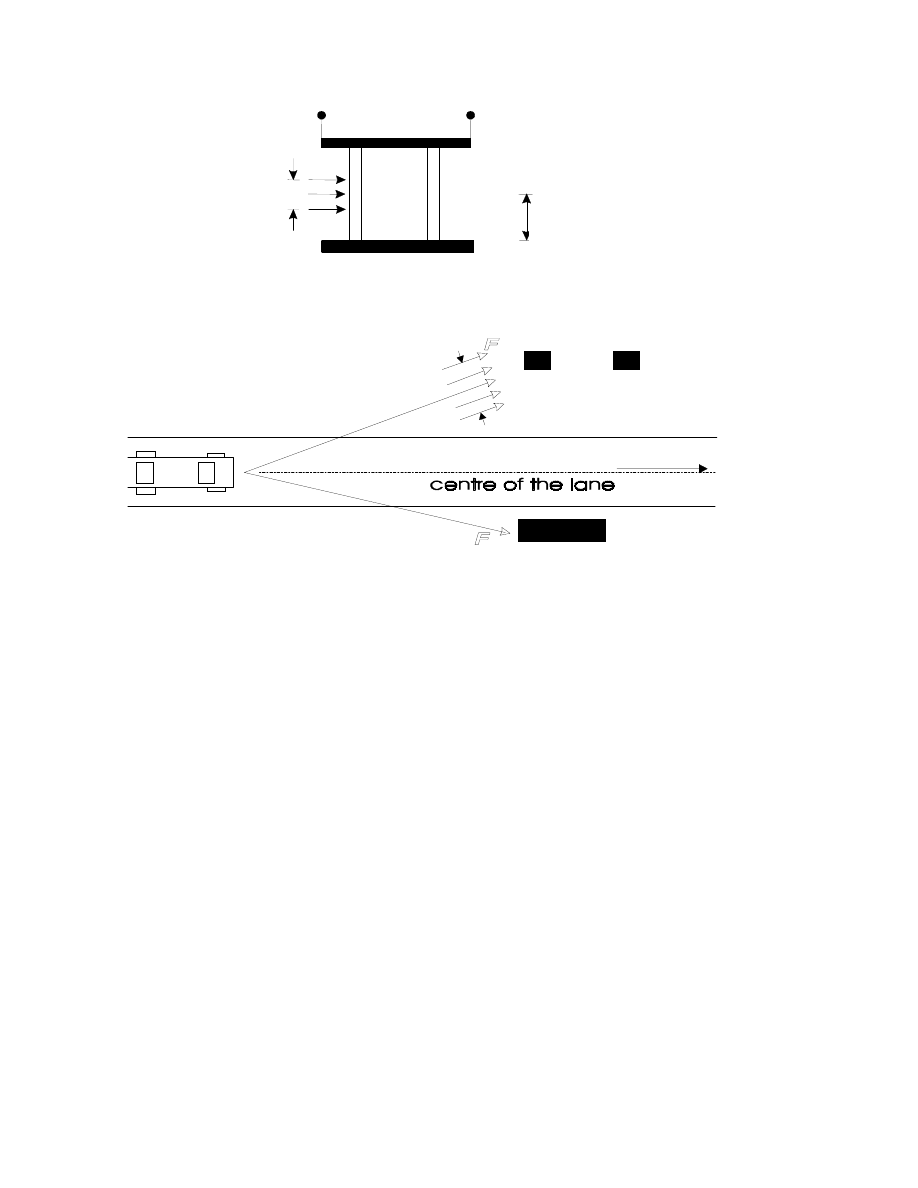
(5) For car impact on the supporting sub-structures the resulting collision force F
should be applied at 0,5 m above the level of the driving surface (see Figure
4.3.1). The recommended force application area is 0,25 m (height) by 1,50 m
(width) or the member width, whichever is the smaller.

page 22
Draft prEN 1991-1-7:2003
NOTE 1: The measures for impact from lorries may be chosen from the National Annex. The
recommended measures are as follows:
For impact from lorries on the supporting sub-structure the resulting collision force F should
be applied at any height between 0.5-1.5 m above the level of the carriageway (see Figure 4.3.1)
or greater where a protective barrier is provided. The force application area is 0,5 m (height) by
1,50 m (width) or the member width, whichever is the smaller.
Table 4.3.2: Impact loads on horizontal structural members above roadways.
Type of traffic
Type of vehicle
Force F
d,x
[kN]
Force F
d,y
[kN]
Motorway
Lorry
1000-2000
500-1000
Country road
(<80 km/hr)
Lorry
750-2000
375-1000
Urban area
(<60 km/hr)
Lorry
500-2000
250-1000
Court yards and parking garages
(<20 km/hr)
Lorry
150-300
75-150
NOTE 1: x = direction of normal travel, y = perpendicular to the direction of normal travel.
NOTE 2: The National Annex may give a choice of the values depending on the consequences of
the impact, taking account of the type of traffic under the bridge, and/or including the effect of
protection measures. The lower values are recommended for the general case and in the absence
of further indications.
NOTE 3: The forces F
d,x
and F
d,y
need not be considered simultaneously
NOTE 4: The application area for the impact force may be taken as 0,25 m (height) by 0,25 m
(width).
4.3.2 – Impact on horizontal structural elements (eg. bridge decks)
(1) Actions due to impact loads from lorries and/or loads carried by the lorries on
horizontal structural elements (eg. bridge decks) above roadways need only
be considered, when adequate values for clearances or other suitable
protection measures to avoid impact are not provided.

page
23
Draft prEN 1991-1-7:2003
NOTE: Adequate values for clearances and suitable protection measures to avoid impact may be
given in the National Annex. The recommended value for adequate clearance, excluding future
re-surfacing of the carriageway under the bridge, to avoid impact is 6.0m.
(2) In cases where verification of static equilibrium or strength or deformation
capacity are required for impact loads from lorries on horizontal structural
elements (eg. bridge decks) above roadways, the rules may be given in the
National Annex.
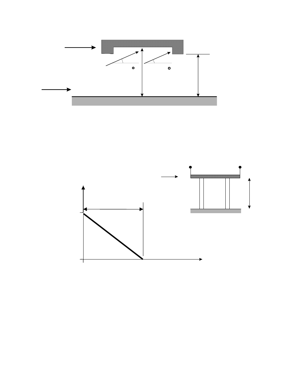
NOTE 1: The recommended rules are as follows.
-- On vertical surfaces the design impact loads are equal to those impact values given in Table
4.3.2, multiplied by a probability factor r (see Figure 4.3.3);
–
On the underside surfaces the same impact loads as above with an upward inclination of 10
o
should be considered (see Figure 4.3.2);
–
In determining the value of h allowance should be made for any possible future reduction
caused by the resurfacing of the carriageway under the bridge.
-
The force application area may be taken as 0,25 m (height) by 0,25 m (width).
NOTE 2 Information on the effect of the distance s can be found in Annex C.
NOTE 3: The value of probability factor r should be based on impact accidental data for other
existing structures. In the absence of such data the recommended value is given in Figure 4.3.3.
page 24
Draft prEN 1991-1-7:2003
Figure 4.3.1:
Collision force on supporting substructures near traffic lanes
0.25m (cars)
0.50m
(lorries)
0.25m(cars)
0.50m(lorries)
0.5m(cars)
0.5 to 1.5m(lorries)
page
25
Draft prEN 1991-1-7:2003
F
h
h
d rivin g d ire c tio n
F
1 0
1 0
Figure 4.3.2:
Collision force on horizontal structural elements (ie. bridge decks) above
roadways
r
h
h
F
0 ,5
6 ,0 m
0 ,0
5 ,0 m
Figure 4.3.3:
Value of the factor r for collision forces on horizontal structural elements
above roadways, depending on the free height h
Direction of Traffic
5.0m or National Limit
F
0.5
0
1.0m above
National Limit
r
1.0m

page 26
Draft prEN 1991-1-7:2003
4.4 Accidental actions caused by fork lift trucks
(1) For buildings where fork lift trucks are present on a regular basis, the dynamic
behaviour of the impacting fork lift truck and the hit structure under non-linear
deformation should be considered so as to determine the impact force.
NOTE 1: Simplifications according to advanced impact design for soft impact are possible
(see Annex C) to determine static equivalent forces F.
NOTE 2: The National Annex may give the choice of static equivalent force F and the height
of application. The following values are recommended:
A horizontal static equivalent design force F = 5W, where W is the weight of a loaded
truck, should be taken into account at a height of 0,75 m above floor level.
NOTE 3: Deformable elements, i.e. guard rails, may help protecting the supporting structure in
case of lacking bearing capacity and have to be designed.
4.5 Accidental actions caused by derailed rail traffic under or adjacent to
structures
4.5.1 Structures spanning across or alongside operational railway lines
4.5.1.1 Introduction
(1) This section sets out rules for derailment actions on supports from derailed trains
under or adjacent to structures. The section also sets out other appropriate measures (both
preventative and protective) to reduce as far as is reasonably practicable the effects of an
accidental impact from a derailed vehicle against supports of structures located above or
adjacent to the tracks and supports carrying superstructures. The specific
recommendations are dependant on the classification of the structure.
NOTE: Derailment actions from rail traffic on bridges carrying rail traffic are specified in EN 1991-2.
4.5.1.2 Classification of structures
(1) P Structures shall be classified according to Table 4.5.1.

page
27
Draft prEN 1991-1-7:2003
Table 4.5.1 Classes of structures subject to impact from derailed traffic
Class
A
Structures that span across or near to the operational railway
that are either permanently occupied or serve as a temporary
gathering place for people or consist of more than one storey.
Class
B
Massive structures that span across the operational railway
such as bridges carrying vehicular traffic or single storey
buildings that are not permanently occupied or do not serve
as a temporary gathering place for people.
NOTE 1: The National Annex should specify the Class of structures to be included in each
consequences class (See clause 3.4).
NOTE 2: The National Annex may specify (as non conflicting, complementary information) the
classification of temporary structures such as temporary footbridges or similar structures used by
the public as well as auxiliary construction works (Part 1-6 of EN1991 refers).
4.5.1.3 Accidental Design Situations in relation to the classes of structure
(1) Derailment of rail traffic under or on the approach to a structure classified as Class A
or B should be considered as an accidental design situation.
(2) Impact on the superstructure (deck structure) from derailed rail traffic under or on the
approach to a structure need not generally be considered.
4.5.1.4 Class A structures
(1) For class A structures, where the maximum line speed at the site is less than
or equal to 120km/h, design values for the static equivalent forces due to
impact on supporting structural elements (e.g. columns, walls) should be
specified.
NOTE: The static equivalent loads and their identification may be given in the National Annex.
Table 4.5.2 gives recommended values.

page 28
Draft prEN 1991-1-7:2003
Table 4.5.2 : Horizontal static equivalent design forces due to impact for
class A structures over or alongside railways
Distance “s” from structural
elements to the centreline of
the nearest track
(m)
Force F
d,x
(kN)
Force F
d,y
(kN)
Structural elements : s < 3 m
To be specified for
the particular project.
Further information is
set out in Annex B.8
To be specified for
the particular project.
Further information is
set out in Annex B.8
For continuous walls and wall
type structures : 3 m
≤ s ≤ 5 m
4 000
1 500
S > 5 m
0
0
NOTE: x = track direction; y = perpendicular to track direction.
(2) For supports that are protected by solid plinths or platforms etc., the value of
forces given in Table 4.5.2 may be reduced. Details of possible reductions
may be given in the National Annex.
(3) The forces F
d,x
and F
d,y
should be applied at a level of 1,8 m above track level
and the design should consider each load case separately.
(4) If the maximum line speed at the site is lower or equal to 50km/h, the values
of the forces in Table 4.5.2 may be reduced by half. Further information is set out
in Annex B7.
(5) Where the maximum permitted line speed at the site is greater than 120 km/h,
the values of the horizontal static equivalent design forces together with
additional preventative and/or protective measures should be specified in the
National Annex or for the particular project.
NOTE: Information may be given in the National Annex or for the individual project. Further
information is given in Annex B7.
4.5.1.5 Class B structures
(1) For Class B structures, particular requirements should be specified.
NOTE: Information may be given in the National Annex or for the individual project. The particular
requirements may be based on a risk assessment. Information on the factors and measures to consider is
given in Annex C4.1.

page
29
Draft prEN 1991-1-7:2003
4.5.2 Structures located in areas beyond track ends
(1) Overrunning of rail traffic beyond the end of a track or tracks (for example at a
terminal station) should be considered as an Accidental Design Situation when the
structure or its supports are located in the area immediately beyond the track ends.
NOTE: The area to be considered as immediately beyond track ends should be specified in the National
Annex.
(2) The measures to manage the risk should be based on the utilisation of the area
immediately beyond the track end and may take into account any measures taken to
reduce the likelihood of an overrun of rail traffic.
(3) Supports to structures should generally not be located in the area immediately beyond
the track ends.
(4) Where supports are required to be located near to track ends, an end impact wall
should be specified in addition to any buffer stop.
NOTE: Particular measures and alternative design values for the static equivalent force due to impact may
be specified in the National Annex or for the individual project. The recommended design values for the
static equivalent force due to impact on the end impact wall is F
dx =
5 000 kN for passenger trains and F
d,x
=
10 000 kN for shunting and marshalling trains. These forces should be applied horizontally and at a level of
1,0 m above track level.
4.6
Accidental actions caused by ship traffic
4.6.1 General
(1) The characteristics to be considered for collisions from ships depend upon the type of
waterway, the flood conditions, the type and draught of vessels and their impact behaviour
and the type of the structures and their energy dissipation characteristics. The types of
vessels that can be expected should be classified according to standard ship characteristics,
see Tables 4.6.1 and 4.6.2.
(2) The impact action is represented by two mutually exclusive load arrangements:
a frontal force F
dx
acting in the longitudinal axis of the pier;
a lateral force F
dy
acting normal to the longitudinal axis of the pier and a friction force F
R
parallel to the longitudinal axis.
The frontal and the lateral force act perpendicular to the surface under consideration.
(3) For ship impact forces hydrodynamic added mass should be taken into account.
4.6.2 Impact from river and canal traffic
(1) For a number of standard ship characteristics and standard design situations, the
recommended frontal and lateral dynamic forces are given in Table 4.6.1. In harbours the forces
given in Table 4.6.1 may be reduced by a factor of 0,5.

page 30
Draft prEN 1991-1-7:2003
Table 4.6.1 Ship characteristics and corresponding dynamic design forces for inland
waterways
CEMT
1)
Class
Reference type
of ship
Length l
(m)
Mass m
(ton)
Force F
dx
(kN)
Force F
dy
(kN)
I
30-50
200-400
2 000
1 000
II
50-60
400-650
3 000
1 500
III
“Gustav König”
60-80
650-1 000
4 000
2 000
IV
Class „Europe“
80-90
1 000-1 500
5 000
2 500
Va
Big ship
90-110
1 500-3 000
8 000
3 500
Vb
Tow + 2 barges
110-180
3 000-6 000
10 000
4 000
Via
Tow + 2 barges
110-180
3 000-6 000
10 000
4 000
Vib
Tow + 4 barges
110-190
6 000-12 000
14 000
5 000
Vicc
Tow + 6 barges
190-280
10 000-18 000
17 000
8 000
VII
Tow + 9 barges
300
14 000-27 000
20 000
10 000
NOTE 1: CEMT: European Conference of Ministers of Transport, classification
proposed 19 June 1992, approved by the Council of European Union 29 October
1993.
NOTE 2: The mass m in tons (1ton=1000kg) includes the total weight of the
vessel, including the ship structure, the cargo and the fuel. It is often referred to
as the displacement tonnage. It does not include the added hydraulic mass.
NOTE 3: For ships of other mass refer to Annex C.
NOTE 4: The forces F
dx
and F
dy
include the effects of added hydraulic mass.
NOTE 5: National values of frontal and lateral dynamic values may be given in
the National Annex.
(2) The friction impact force acting simultaneous with the lateral impact shall be calculated by
F
R
= f F
dy
(4.6.1)
where f = 0,4 is the friction coefficient.
(3) The impact forces shall be applied at a height above the maximum navigable water level
depending on the ships draught (loaded or in ballast). In the absence of detailed information, the
force shall be applied at a height of 1,50 m above the relevant water level. An impact area b x h
or b
pier
x 0,5 m for frontal impact and b x h = 1,0 m x 0,5 m for lateral impact can be assumed.

page
31
Draft prEN 1991-1-7:2003
(4) In the absence of a structural dynamic analysis a dynamic amplification factor should be used
of 1,3 for frontal impact and 1,7 for lateral impact.
NOTE: For information on dynamic ship impact analysis, see Annex C.
(5) Under certain conditions it may be necessary to assume that the ship is lifted over an
abutment or foundation block prior to colliding with columns.
(6) The superstructure of a bridge (the deck) should be designed to sustain an equivalent static
force in any longitudinal direction if higher forces are not to be expected.
NOTE: The National Annex may provide a value for the equivalent static force. The
recommended value is 1MN.
4.6.3 Impact from seagoing vessels
(1) The recommended frontal dynamic impact forces are given in Table 4.6.2. In harbours the
forces given in Table 4.6.2 may be reduced by a factor of 0,5.

page 32
Draft prEN 1991-1-7:2003
Table 4.6.2 Ship characteristics and corresponding nominal dynamic design forces for sea
waterways
Class of ship
Length l
(m)
Mass m
(ton)
Force F
dx
(kN)
Force F
dy
(kN)
Small
50
3 000
4 000
2000
Medium
100
10 000
15 000
7000
Large
200
40 000
75 000
37000
Very large
300
100 000
200 000
100000
NOTE 1: The forces given correspond to a velocity of about 2,0 m/s.
NOTE 2: National values of dynamic design forces may be given in the National
Annex.
NOTE 3: Interpolation of the above values is permitted.
NOTE 4: The forces F
dx
and F
dy
include the effects of added hydraulic
mass.
NOTE 5: The mass m in tons (1ton=1000kg) includes the total weight of the
vessel, including the ship structure, the cargo and the fuel. It is often referred to as
the displacement tonnage. It does not include the added hydraulic mass.
(2) In the absence of a dynamic analysis, a frontal impact factor of 1,3 and a lateral impact factor
of 1,7 is recommended
(3) Bow, stern and broad side impact should be considered where relevant; for side and stern
impact the forces given in Tables 4.6.2 may be multiplied by a factor of 0.3.
(4) Bow impact should be considered for the main sailing direction with a maximum deviation of
30
o
.
(4) The frictional impact force acting simultaneously with the lateral impact shall be calculated by:
F
R
= f F
dy
(4.6.2)
where:
f
is the friction coefficient, f = 0,4.
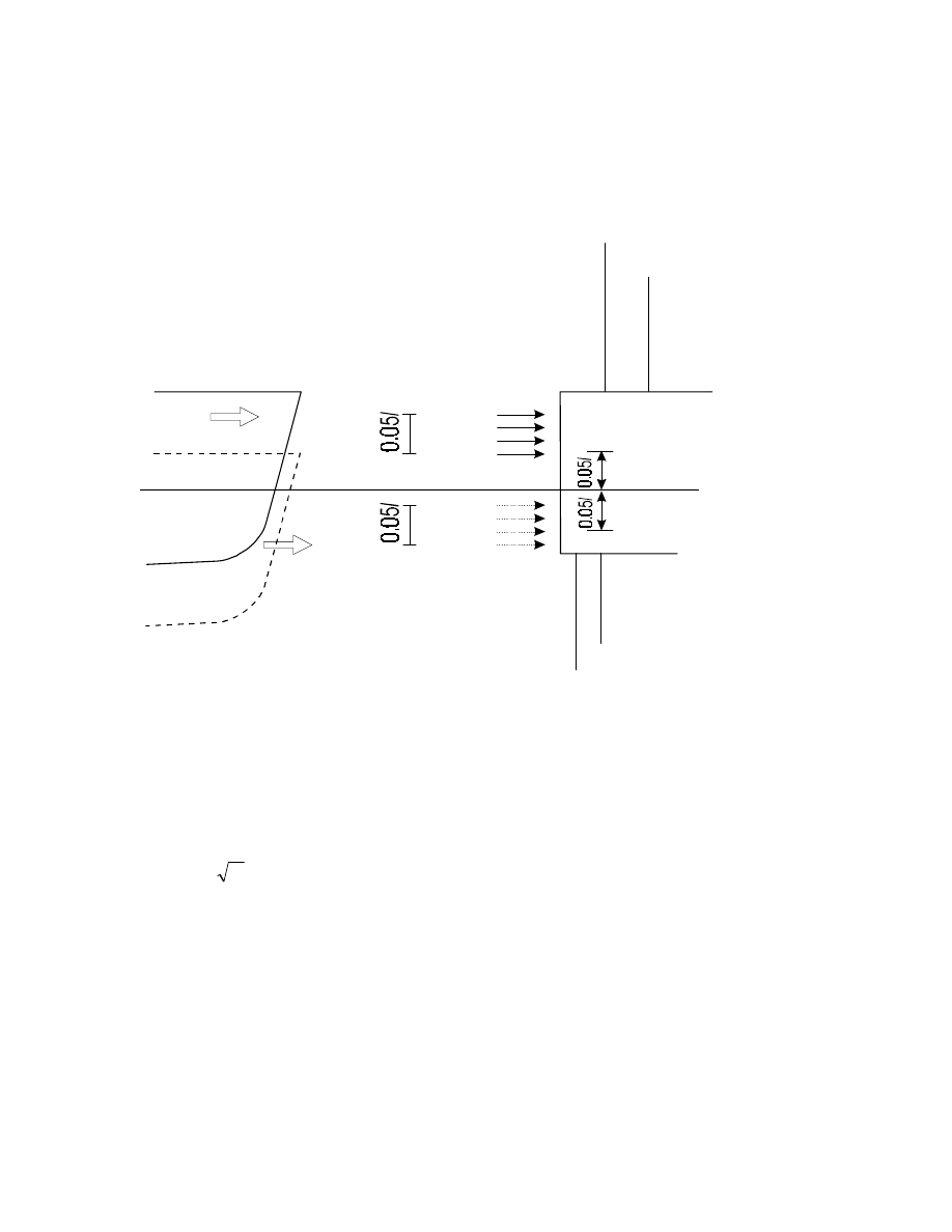
(6) The point of impact depends upon the geometry of the structure and the size of the vessel.
The impact area is 0,05l high and 0,1l broad, unless the structural element is smaller (l = ship
length).
NOTE: As a guideline the most unfavourable mid impact point may be taken as ranging from
0,05l below to 0,05l above the design water levels (see Figure 4.6.2).
(7) The forces on a superstructure depend upon the height of the structure and the type of ship to
be expected. In general the force on the superstructure of the bridge will be limited by the yield
strength of the ships’ superstructure.
page
33
Draft prEN 1991-1-7:2003
NOTE: A range of 5 to 10 percent of the bow impact force may be considered as a guideline.
Figure 4.6.2:
Possible impact areas for ship collision
4.7 Accidental actions caused by helicopters
(1) If the roof of a building has been designated as a landing pad for helicopters, a heavy
emergency landing force should be considered, the vertical static equivalent design force F
d
being equal to:
m
C
F
=
d
(4.71)
where:
C
is 3 kN kg
-0.5
m
is the mass of the helicopter kg.
(2) The force due to impact should be considered to act on any part of the landing pad as well as
on the roof structure within a maximum distance of 7 m from the edge of the landing pad. The
area of impact may be taken as 2 m
× 2 m.

page 34
Draft prEN 1991-1-7:2003
Section 5
Internal Explosions
5.1 Field of application
(1) Explosions shall be considered in all parts of the building where gas is burned or regulated or
where otherwise explosive material such as explosive gases or liquids forming explosive vapour
or gas being stored. Solid high explosives are not covered in this code.
(2) Dust, gas or vapour explosions shall be considered for design purposes unless the probability
is acceptably low that such dust, gas or vapour could ever be present within the building.
(3) This setion defines actions due to internal explosions of
–
dust explosions in rooms and silos
–
dust explosions in energy ducts
–
gas and vapour explosions in rooms and closed sewage bassins
–
gas and vapour explosions in energy ducts
–
gas and vapour explosions in road and rail tunnels
(4) Construction works to be considered are chemical facilities, sewage works, buildings with piped
gas installations or canister gas, energy ducts, road and rail tunnels.
5.2 Representation of action
(1) In this context an explosion is defined as a rapid chemical reaction of dust, gas or vapour in
air. It results in high temperatures and high overpressures. Explosion pressures propagate as
pressure waves.
(2) The pressure generated by an internal explosion depends primarily on the type of dust, gas or
vapour, the percentage of dust, gas or vapour in the air and the uniformity of dust, gas or vapour
air mixture, the ignition source, the presence of obstacles in the enclosure, the size and shape of
the enclosure in which the explosion occurs, and the amount of venting or pressure release that
may be available.
(3) Explosion pressures on the structural elements should be estimated taking into account, as
appropriate, reactions transmitted to the structural elements by non-structural elements.
(4) Due allowance should be made for probable dissipation of dust, gas or vapour throughout the
building, for venting effects, for the geometry of the room or group of rooms under consideration
etc.
(5) Design situations classified as Category 1 (see section 3): no specific consideration of the effects
of an explosion is necessary other than complying with the rules for connections and interaction
between components provided in EN 1992 to EN 1999.
(6) Design situations classified as Category 2 or 3: key elements of the structure shall be
designed to resist actions either using analysis based upon equivalent static load models or by
applying prescriptive design/detailing rules.

page
35
Draft prEN 1991-1-7:2003
(7) For structures in Category 2, for a single room event, an equivalent static load model analysis
of key elements of a structure may be carried out using either the procedures described in 5.3(3).
Note: alternatively one may use the strategies for damage due to local failure from any undefined cause as
outlined in Annex A.
(8) For structures in Category 3 it is recommended to consider the use of dynamic analysis as
described in Annex B.
(9) Advanced design for explosions may include one or several of the following aspects:
–
explosion pressure calculations, including the effects of confinements and breaking panels;
–
dynamic non linear structural calculations;
–
probabilistic aspects and analysis of consequences;
–
economic optimisation of mitigating measures.
5.3 Principles for design
(1) Progressive collapse of all kinds of structures due to an internal explosion shall not be
possible. Elements which are not key elements may fail; key elements may be damaged so long
as they retain their structural integrity.
(2) To reduce confined explosion pressures and to limit the consequences of explosions the
following guidelines may be applied :
–
the structure capable of resisting the maximum explosion overpressure;
–
use of venting panels with defined venting pressures;
–
separation of sections of the structure with explosion risks from other sections;
–
limiting the area of sections with explosion risks;
–
dedicated protective measures between sections with explosion risks from other sections to
avoid explosion and pressure propagation.
NOTE: The estimated peak pressures may be higher than the values presented in Annex D of
this part, but these can be considered in the context of a maximum load duration of 0.2 s and
plastic ductile material behaviour (assuming appropriate detailing of connections to ensure ductile
behaviour).
(3) The explosive pressure acts effectively simultaneously on all of the bounding surfaces of the
enclosure.
(4) Vents should be placed close to possible ignition source if known or at turbulence-producing
devices. They should discharge to a location that cannot endanger personnel. The vent panel
must be restrained such that not becoming a missile in case of explosion

page 36
Draft prEN 1991-1-7:2003
(5) The venting openings should be initiated by a low pressure and should be as light as possible.
If windows are used no danger to persons from gas fragments or other structural elements should
result.
(6) Reaction forces due to venting should be taken into account by dimensioning the support
elements.
(7) After the positive phase of the explosion (with an overpressure), a second phase follows
with an underpressure. For relevant structures this effect has to be considered in the design.

page
37
Draft prEN 1991-1-7:2003
Annex A
(informative)
Robustness of Buildings - Design for Consequences of Localised Failure from an
Unspecified Cause
A1 Scope and field of application
(1) This Annex A provides rules and methods for designing buildings to sustain an extent
of localised failure from an unspecified cause without disproportionate collapse.
Adoption of this strategy is likely to ensure that the building is sufficiently robust to
sustain a limited extent of damage or failure, depending on the Consequences Class
(See 3.4), without collapse.
A2 Symbols
A3 Introduction
(1) Designing the building such that neither the whole building nor a significant part of
it will collapse if localised damage were sustained, is an acceptable strategy, as
stated in Section 3, for ensuring that the building is sufficiently robust to survive a
reasonable range of undefined accidental actions.
(2) The minimum period that a building needs to survive following an accident should
be that needed to facilitate the safe evacuation and rescue of personnel from the
building and its surroundings. Longer periods of survival may be required for
buildings used for handling hazardous materials, provision of essential services, or
for national security reasons.
A4 Consequences Classes of Buildings
(1) Table A1 provides a recommended categorisation of building types/occupancies to
consequence classes. This categorisation relates to the low, medium and high
consequences classes given under 3.4 (1).

page 38
Draft prEN 1991-1-7:2003
Table A1 Recommended categorisation of Consequences Classes
Class
Building Type and Occupancy
1
Single occupancy houses not exceeding 4 storeys.
Agricultural buildings.
Buildings into which people rarely go, provided no part of the
building is closer to another building, or area where people do go,
than a distance of 1
1
/
2
times
the building height.
2
Lower Risk
Group
5 storey single occupancy houses.
Hotels not exceeding 4 storeys.
Flats, apartments and other residential buildings not exceeding 4
storeys.
Offices not exceeding 4 storeys.
Industrial buildings not exceeding 3 storeys.
Retailing premises not exceeding 3 storeys of less than 1000m
2
floor area in each storey.
Single storey Educational buildings
2
Upper Risk
Group
Hotels, flats, apartments and other residential buildings greater than
4 storeys but not exceeding 15 storeys.
Educational buildings greater than single storey but not exceeding
15 storeys.
Retailing premises greater than 3 storeys but not exceeding 15
storeys.
Hospitals not exceeding 3 storeys.
Offices greater than 4 storeys but not exceeding 15 storeys.
All buildings to which members of the public are admitted in
significant numbers and which contain floor areas not exceeding
1000 m
2
at each storey.
Non- automatic car parking not exceeding 6 storeys.
Automatic car parking not exceeding 15 storeys.
Leisure Centres.less than 2000m
2
3
All buildings defined above as Class 2 Lower and Upper
Consequences Class that exceed the limits on area and number of
storeys.
All buildings to which members of the public are admitted in
significant numbers.
Stadia accommodating more than 5000 people
Leisure Centres greater than 2000m
2
NOTE 1: For buildings intended for more than one type of use the “Consequences Class” should be that
pertaining to the most onerous type.

page
39
Draft prEN 1991-1-7:2003
NOTE 2: In determining the number of storeys basement storeys may be excluded provided such basement
storeys fulfil the requirements of "Consequences Class 2 Upper Group".
A5 Recommended Strategies.
(1) Adoption of the following recommended strategies should ensure that the building
will have an acceptable level of robustness to sustain localised failure without a
disproportionate level of collapse.
a) For buildings in Consequences Class 1:
Provided the building has been designed and constructed in accordance with the rules
given in EN1992 to 1999 for satisfying stability in normal use, no further specific
consideration is necessary with regard to accidental actions from unidentified causes.
b) For buildings in Consequences Class 2 (Lower Group):
Provide effective horizontal ties, or effective anchorage of suspended floors to walls,
as defined in A6.1 and A6.2 respectively for framed and load-bearing wall
construction.
c) For buildings in Consequences Class 2 (Upper Group):
Provide effective horizontal ties, as defined in A6.1 and A6.2 respectively for framed
and load-bearing wall construction (See definition), together with:
[Editorial Note: The term “Load-bearing wall construction” is intended to include masonry
cross-wall construction and similar forms of construction comprising walls formed with close
centred timber or lightweight steel section studs.]
- effective vertical ties, as defined in A7, in all supporting columns and walls, or
alternatively,
- ensure that upon the notional removal of each supporting column and each beam
supporting a column, or any nominal section of load-bearing wall as defined in
A8 below, (one at a time in each storey of the building) that the building remains
stable and that any local damage does not exceed a certain limit.
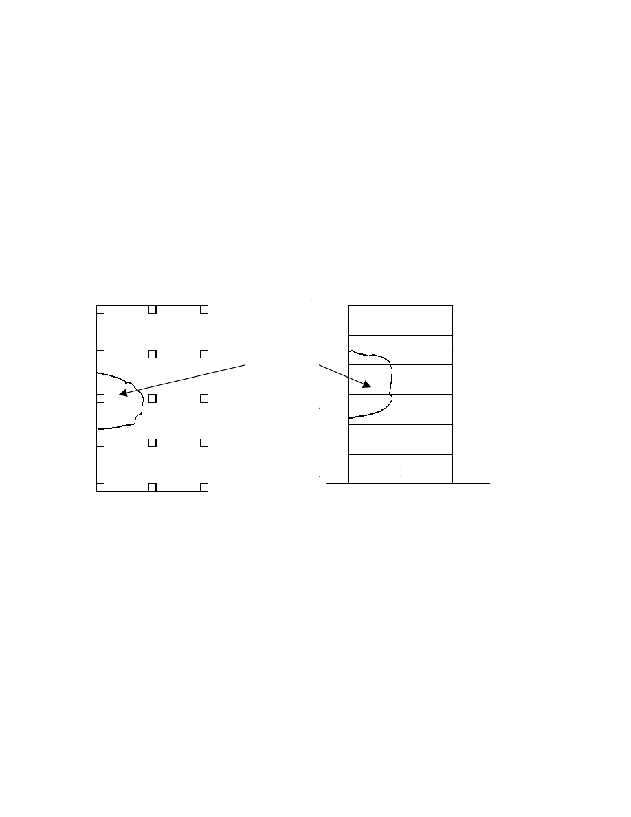
NOTE 1 The limit of admissible local damage may be specified in the National Annex. This may
be different for each type of building. The recommended value is 15% of the floor in each of 2
adjacent storeys. See Figure A1.
Where the notional removal of such columns and sections of walls would result in an
extent of damage in excess of the above limit, or other such limit specified in the
National Annex, then such elements should be designed as a "key element". See A9.
page 40
Draft prEN 1991-1-7:2003
In the case of buildings of load-bearing wall construction, the notional removal of a
section of wall, one at a time, is likely to be the most practical strategy to adopt.
d) For Buildings in Consequences Class 3:
A systematic risk analysis of the building should be undertaken taking into account
all the normal hazards that may reasonably be foreseen, together with any abnormal
hazards.
NOTE 1: The National Annex may give the hazards to be taken into account.
NOTE 2: Guidance on the preparation of a risk analysis is included in Annex B.
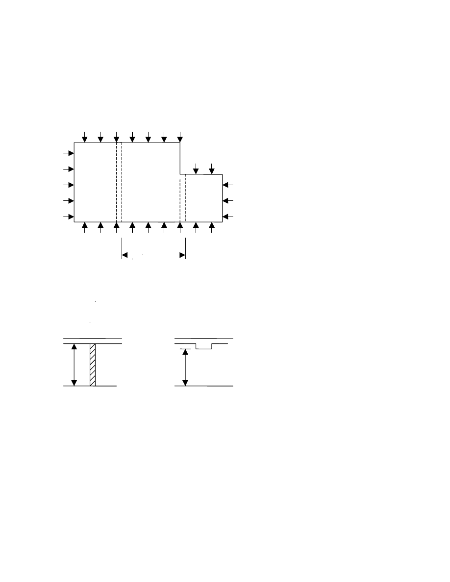
Figure A1 – Recommended Limit of admissible damage
PLAN
SECTION
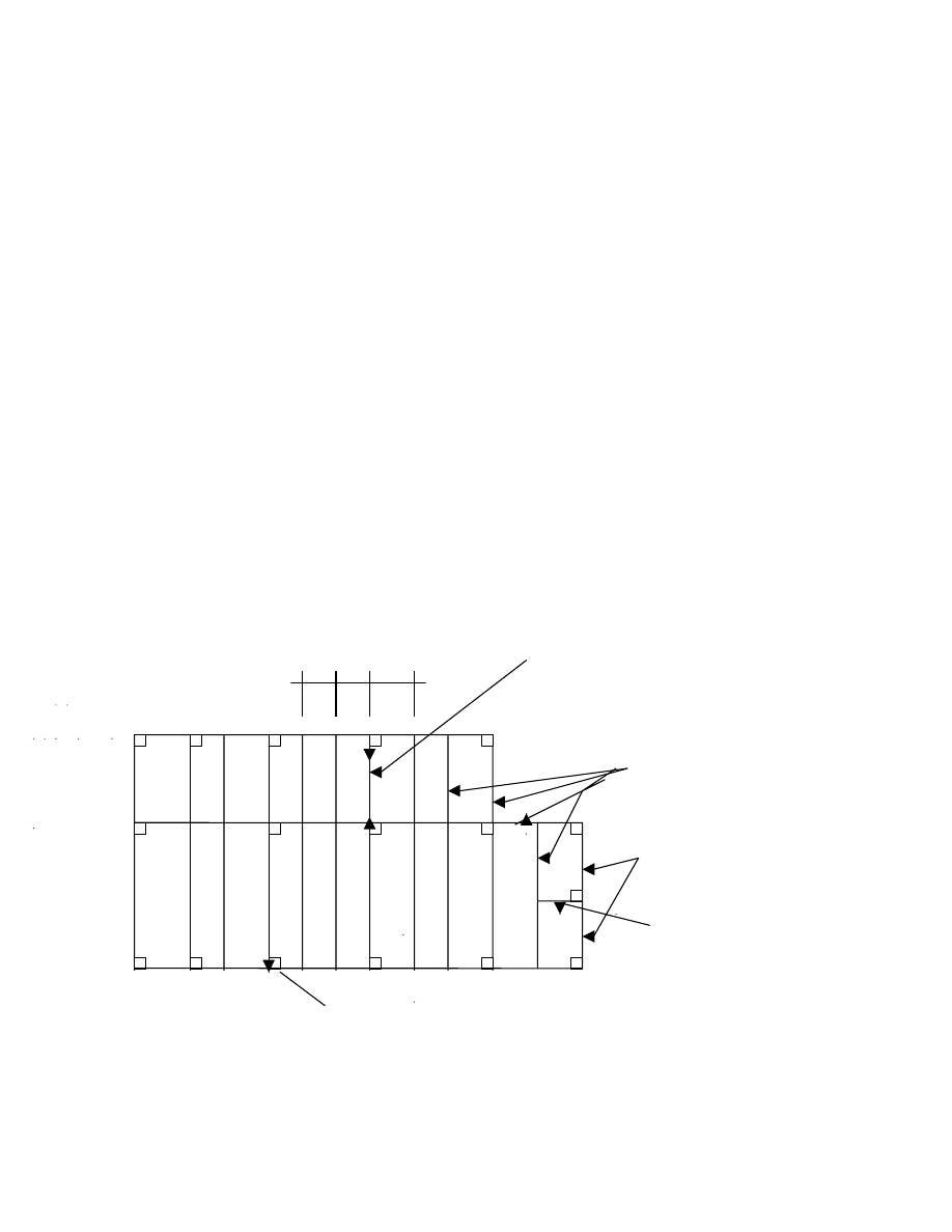
A6 Effective horizontal ties
A6.1 Framed Structures:
1)
Effective horizontal ties should be provided around the perimeter of each floor
and roof level and internally in two right angle directions to tie the column and
wall elements securely to the structure of the building. The ties should be
continuous and be arranged as closely as practicable to the edges of floors and
lines of columns and walls. At least 30% of the ties should be located within the
close vicinity of the lines of columns and walls.
NOTE: See example in Figure A2.
Local
damage not
exceeding
15% of floor
area in each
of 2 adjacent
Local
damage not
exceeding
15% of floor
area in each
of 2 adjacent
storeys.
page
41
Draft prEN 1991-1-7:2003
2)
Effective horizontal ties may comprise rolled steel sections, steel bar
reinforcement in concrete slabs, or steel mesh reinforcement and profiled steel
sheeting in composite steel/concrete floors (if directly connected to the steel
beams with shear connectors). The ties may consist of a combination of the above
types.
3)
Each continuous tie, including its end connections, should be capable of
sustaining a design tensile load of “Ti” for the accidental limit state in the case of
internal ties, and “Tp” , in the case of perimeter ties, equal to the following values:
for internal ties, T
I
= 0.8(g
k
+ q
k
)sL or 75kN, whichever the greater.
for perimeter ties Tp
= 0.4(g
k
+ q
k
)sL or75kN, whichever the greater.
Where s = the spacing of ties.
L = the span of the tie.
= combination factor according to the accidental load combination.
NOTE:
See example in Figure A2.
4)
Members used for sustaining non-accidental loading may be utilised for the above
ties without consideration of the combination of actions as given in EN 1990.
Figure A2 - Example of effective horizontal tying of a 6 storey framed office
building.
2m 2m 3m 6 m span beam as internal tie.
All beams designed
to act as ties.
perimeter ties.
Tie anchoring
column.
Edge column

page 42
Draft prEN 1991-1-7:2003
NOTE: Example of calculating the accidental design tensile force T
i
in 6m span beam.
Characteristic loading : q
k
=5.0kN/m
2
and g
k
=3.0kN/m
2
T
I
= 0.8(3.00 + 1.0 x 5.00) 3+2 . 6.0 = 96kN (being greater
2
than 75kN)
A6.2 Load-bearing wall construction.
(1) For Class 2 buildings (Lower Group)
Provide robustness by adopting a cellular form of construction designed to
facilitate interaction of all components including an appropriate means of
anchoring the floor to the walls.
(2) For Class 2 buildings (Upper Group)
Provide continuous effective horizontal ties in the floors. These should be internal
ties distributed throughout the floors in both orthogonal directions and peripheral
ties extending around the perimeter of the floor slabs within a 1.2m width of slab.
The design tensile load in the ties should be determined as follows:
For internal ties T
I
= the greater of F
t
kN/m or F
t
(g
k
+ q
k
).z kN/m
7.5 5
Where Ft = 60 kN/m or 20 + 4n
s
kN/m, whichever is less.
N
s
= the number of storeys.
z = the lesser of the greatest distance in metres in the direction
of the tie, between the centres of the columns or other vertical
loadbearing members whether this distance is spanned by a single
slab or by a system of beams and slabs;
or, 5 times the clear storey height H.
For peripheral ties T
p
= F
t
Where Ft = 60kN or 20 + 4n
s
kN, whichever is less
page
43
Draft prEN 1991-1-7:2003
Plan
H
Flat slab
Beam and slab
H
Figure A3 – Definition of factors.
La
Section
Plan
z

page 44
Draft prEN 1991-1-7:2003
A7 Effective vertical ties
1)
Each column and wall should be tied continuously from the foundations to roof level.
2)
In the case of framed buildings (eg. steel or reinforced concrete structures) the columns and walls
carrying vertical actions should be capable of resisting an accidental design tensile force equal to
the largest design vertical permanent and variable load reaction applied to the column from any one
storey. Such accidental design loading should not be assumed to act simultaneously with normal
loading.
3)
In the case of load-bearing wall construction the vertical ties may be considered effective if:
i)
In the case of masonry walls their thickness is at least 150mm thick and if they have a
minimum compressive strength of 5N/mm
2
in accordance with EN1996-1-1.
ii)
The clear height of the wall, ha, measured in metres between faces of floors or roof does
not exceed 20 t, where t is the thickness of the wall in metres.
iii)
The vertical tie force T is 34A H
2
N, or 100kN/m of wall,
8000 t
whichever is the greater,
where A = the cross-sectional area in mm
2
of the wall measured on plan, excluding the
non- loadbearing leaf of a cavity wall.
iv)
The vertical ties are grouped at 5m maximum centres along the wall and occur no greater
than 2.5m from an unrestrained end of wall.
A8 Nominal section of load-bearing wall
1) The nominal length of load-bearing wall construction referred to in A5(c) should be taken as
follows:
-
in the case of a reinforced concrete wall, a length not exceeding 2.25H
-
in the case of an external masonry, or timber or steel stud wall, the length measured between
vertical lateral supports.
- in the case of an internal masonry, or timber or steel stud wall, a length not exceeding 2.25H
where H is the storey height in metres.
A9 Key Elements
1) A "key element", as referred to in A5, should be capable of sustaining an accidental design action
of A
d
applied in horizontal and vertical directions (in one direction at a time) to the member and any
attached components having regard to the ultimate strength of such components and their connections.
Such accidental design loading should be assumed to act simultaneously with normal loading. This will
require use of the combination of actions rules given in EN1990, 6.4.3.3.
NOTE: The National Annex may give a value for A
d .
The recommended value for A
d
is 34kN/m
2
.
page
45
Draft prEN 1991-1-7:2003
Annex B
(Informative)
(It is the intention to amalgamate the contents of this Annex in future editions of EN1990, Basis of
Design.)
Guidance for Risk Analysis
B1 Introduction
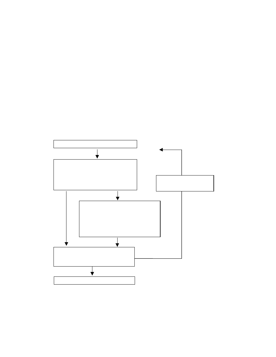
(1) This annex covers the elements that ideally comprise total risk analyses. This annex
can be uses as a guideline for the planning, execution and use of risk analyses. A general
overview is presented in Figure B1.
Definition of scope and limitations
Qualitative Risk analysis
• hazard identification
• hazard scenarios
• description of consequences Reconsideration
• definition of measures of scope and assumptions
Quantitative Risk Analyisis
• inventory of uncertainties
• modelling of uncertatinties
• probabilistic calculations
• quantification of consequences
• calculation of risks
Risk management
• risk acceptance criteria
• decision on measures
Presentation
Figure B1: Overview of Risk Analysis

page 46
Draft prEN 1991-1-7:2003
B2 Definitions
Acceptance criteria: Criteria based on regulations, standards, experience and/or
theoretical knowledge used as a basis for decisions about acceptable risk. Acceptance
criteria may be expressed verbally or numerically.
Consequence: A possible result of an undesired event. Consequences may be expressed
verbally or numerically to define the extent of injury to humans, or environmental or
material damage.
Hazard: A hazard is a set of conditions that may lead to undesirable or adverse events.
Risk: Risk designates the danger that undesired events represent for humans, the
environment or material values. Risk is expressed in the probability and consequences of
these events.
Risk analysis: A systematic approach for describing and/or calculating risk. Risk analysis
involves the identification of undesired events, and the causes, likelyhoods and
consequences of these events.
Risk evaluation: A comparison of the results of a risk analysis with the acceptance criteria
for risk and other decision criteria.
Safety management: Systematic measures undertaken by an organization in order to
attain and maintain a level of safety that complies with defined objectives.
Undesired event: An event or condition that can cause human injury or environmental or
material damage.
B3
Description of the scope of a risk analysis
(1) The subject, background and objectives of the risk analysis shall be described. The
description should include relevant limitations and shall specify the operating conditions
covered by the risk analysis. The description will show which parties are affected by the
problems concerned, and in what way. The decisions that are to be made, the criteria for
decision and the decision-makers shall be identified.
(2) The undesired events that are considered relevant for inclusion in the analysis should
be described and it shall be stated where they occur in the subject for analysis. Criteria
for not including undesired events in a causal analysis and/ or consequence analysis shall
be given.
(3) All technical, environmental, organizational and human circumstances that are
relevant to the activity and the problem being analyzed, shall be stated sufficiently
detailed.
(4) All presuppositions, assumptions. and simplifications made in connection with the risk
analysis should be stated.
NOTE: It is crucial that the assumptions on which the analysis is based are followed up by, for example,
including them as part of the specifications for detailed design and operation.
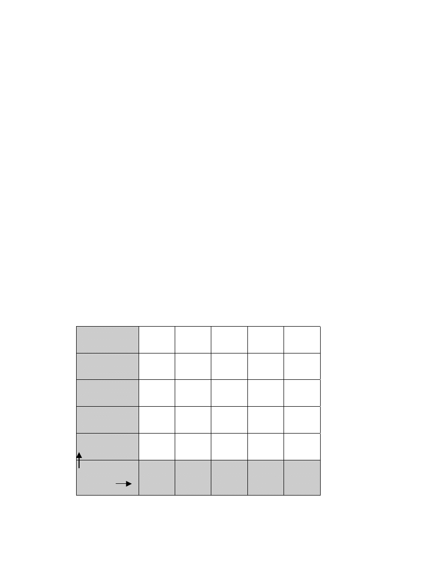
page
47
Draft prEN 1991-1-7:2003
B4
Procedure and methods
(1) The risk analysis has a descriptive (qualitative) part and may, where relevant and
possible, also have a numerical (quantitative) part.
(2) The consequence analysis should consider both immediate consequences and those
that arise after a certain time has elapsed. The consequences may be: casualties,
injuries, psychological damage, monetary values or environmental values.
(3) In the qualitative risk part of the risk analysis all hazards and corresponding hazard
scenarios have to be identified. Identification of hazards and hazard scenarios is a crucial
task to a risk analysis. It requires a detailed examination and understanding of the
system. For this reason a variety of techniques have been developed to assist the
engineer in performing this part of the job (e.g. PHA, HAZOP, fault tree, event tree,
decision tree, causal networks, etc).
(4) In the quantitative part of the risk analysis probabilities will be estimated for all
undesired events and their subsequent consequences. The probability estimations are
usually at least partly based on judgement and may for that reason differ quite
substantially from the actual failure frequencies.
(5) If damages can be expresses in numbers, we may present the risk as the
mathematical expectation of the consequences of an undesired event. A possible way of
presenting risks is indicated in Figure B2.
very small
X
small
X
medium
X
Large
X
very large
X
consequence
probability
>0.1
0.01
0.001
0.0001
0.00001
Figure B2: Possible presentation diagram for the outcome of a quantitative risk analysis

page 48
Draft prEN 1991-1-7:2003
(6) Any uncertainty in calculations/figures due to the data and models used, should be
discussed. This includes evaluating:
• the relevance of the data used
• the possibility of drawing correct conclusions on the basis of the data used
• all presuppositions made in connection with the data used
• all adjustments of the data used
• all
subjective
estimates
• all simplifications and assumptions in models
• all approximations in the calculations
If possible the uncertainty should be quantified.
(7) The Risk analysis will be terminated at a level that is appropriate considering, for
example:
• the objective of the risk analysis and the decisions to be made
• the limitations made at an earlier stage in the analysis
• the availability of relevant or accurate data
• the consequences of the undesired events (some events can be omitted from the
analysis because their consequences are insignificant). These stopping rules will be
stated.
(8) The assumptions upon which the analysis is based should be reconsidered when the
results of the analysis are available. Sensitivities should be quantified.
B5
Risk acceptance and mitigating measures
(1) Given a risk it has to be decided whether it will be accepted or whether mitigating
(structural or nonstructural) measures will be specified.
(2) In risk acceptance usually the ALARA (as low as reasonably achievable) principle is
being used. According to this principle two risk levels are specified: if the risk is below
the lower bound no measures need to be taken; if it is above the upper bound the risk
is considered as unacceptable. If the risk is between the upper and lower bound an
economical optimal solution is being sought for.
(3) Risk acceptance levels are usually formulated on the basis of the following two
criteria:
• The Individual acceptable level of risk: Individual risks are usually expressed as Fatal
Accident Rates. They can be expressed as an annual fatality probability or as the
probability per time unit of a person being killed when actually being involved in a
specific activity.
• The socially acceptable level of risk: The social acceptance of risk to human life, which
may vary with time, is often presented as an F-N-curve, indicating a maximum yearly
probability of having an accident with more then N casualties.
Alternatively, concepts like Value for Fatality Prevented or Quality of life index, may be
used.
Criteria specifications can be found in national regulations, standards, experience and/or
theoretical knowledge used as a basis for decisions about acceptable risk. Acceptance
criteria may be expressed verbally or numerically. More information can be specified in
the National Annex.

page
49
Draft prEN 1991-1-7:2003
B6
Presentation of results and conclusions
(1) The results of the qualitative ad ( if available) the quantitative analysis shell be
presented as a list of consequences and probabilities and their degree of acceptance
should be discussed.
(2) All data sources and data that have been used to carry out a risk analysis should be
specified.
(3) All the essential assumptions, presuppositions and simplifications that have been
made should be summarized so that the validity and limitations of the risk analysis are
made clear.
(4) Recommendations for measures to mitigate risk that naturally arise from the risk
analysis should be stated.
B7
Applications to buildings and civil engineering structures
B7.1 General
(1) In order to mitigate the risk in relation with accidental or other extreme events in
buildings and civil engineering structures one or more of the following measures may be
taken:
• Structural measures, that is by designing strong structural elements or by designing for
second load paths in case of local failures.
• Nonstructural measures, that is by a reduction of the event probability, the action
intensity or the consequences.
(2) Theoretically, the probabilities and effects of all accidental and extreme actions (fire,
earth quake, impact, explosion, extreme climatic actions) should be simulated for all
possible action scenarios. Next the consequences should be estimated in terms of number
of casualties and economic losses. Various measures can be compared on the basis of
economic criteria. This in fact is a standard risk analysis as described in B.2 – B6. Very
often nonstructural measures (like sprinklers in the case of fire) will prove to be very
efficient.
(3) The approach mentioned under (2) does not work for unforseeable hazards (design or
construction errors, unexpected deterioration, etc). As a result more global damage
tolerance design strategies (see Annex A) have been developed, like the classical
requirements on sufficient ductility and tying of elements. One very specific approach, in
this respect, is that one considers the situation that a structural element (beam, column)
has been damaged, by whatever event, to such an extend that its normal load bearing
capacity has vanished almost completely. For the remaining part of the structure it is then
required that for some relatively short period of time (repair period T) the structure can
withstand the "normal" loads with some prescribed reliability:
P(R < S in T | one element removed) < p
target

page 50
Draft prEN 1991-1-7:2003
The target reliability depends on the normal safety target for the building, the period under
consideration (hours, days or months) and the probability that the element under
consideration is removed (by other causes then already considered in design).
(4) For conventional structures it should, at least in theory, be possible to include all relevant
collapse origins in the design. Of course, it will always be possible to think of failure causes
not covered by the design, but those will have a remote likelihood and may be disregarded
on the basis of decision theoretical arguments. For those structures the approach in clause
(2) may work. In many cases, in order to avoid complicated analyses, one may also choose
for the strategy mentioned in (3).
(5) For unconventional structures (very large structures, new design concepts, new
materials) the probability of having some unspecified failure cause should be considered as
substantial. In those cases a combined approach of the methods described under (2) and
(3) is recommended.
page
51
Draft prEN 1991-1-7:2003
B7.2 Modelling of risks from extreme events
x
2
x
1
event E
magnitude M
time t
Figure B3:
Ingredients for the extreme event modelling
(1) General Format
As part of a Risk Analysis one may have to use extreme loading events like earth quakes,
explosions, collisions etc. The general model for such an event may be constituted out of the
following ingredients (figure B3):
• A
triggering
event
E at some place and at some point in time; the triggering event may be an
earth quake, a fire ignition, an explosion, a mechanical failure aboard a vehicle or ship,
etceteras.
• The
magnitude
M of the energy involved in the event and possibly some other parameters.
• The physical interactions between the event, the environment and the structure, leading to the
exceedance of some limit state in the structure.
The occurence of the triggering event E may often be modelled as events in a Poisson process of
intensity
λ
(t,x) per unit volume and time unit, t representing the point in time and x the location in
space (x
1
, x
2
, x
3
). The probability of occurrence of failure during the time period up to time T is
then (for small probabilities) given by
x
x
x
x
d
dm
)
;
m
(
f
)
,
m
|
0
Z
(
P
dt
)
,
t
(
)
T
(
P
M
0
T
0
R
f
3
<
λ
≈
∫
∫
∫
∞
(B1)
where f
M
(m;x) is the probability density function of the random magnitude M of the event E
occurring at the place x, the symbol Z represents the limit state function for the failure mechanism
under consideration such that Z > 0 is the event of no failure.
Given the exceedance of a limit state, the consequences C of such an event should be evaluated.
The product of consequences and failure probability is the expected loss or risk. The integrated
risk for a period of time T , taking into account the discount rate r based on the asymptotic
formula (B1) is given by:
x
x
x
x
d
dm
)
;
m
(
f
)
,
m
|
0
Z
(
P
dt
)
,
t
(
e
)
t
(
C
)
T
(
R
M
0
rt
T
0
R
3
<
λ
≈
∫
∫
∫
∞
−
(B2)
page 52
Draft prEN 1991-1-7:2003
For T
→
∞
and if the intensity
λ
(t,x) and the failure consequence function C(t) are independent of
t, this risk approaches
x
x
x
x
d
dm
)
;
m
(
f
)
,
m
|
0
Z
(
P
)
(
C
r
1
R
M
0
R
3
<
λ
≈
∫
∫
∞
(B3)
(2) Application to impact from vehicles
For this application equation (B1) is further developed for the case of impact loading by vehicles
on highways.
Q
B
r
x
d
b
α
V
0
ϕ
Figure B4: A vehicle leaves the intended course at point Q with velocity v
0
and angle
α. A structural element
at distance r is hit with velocity v
r
.
Consider a structural element in the vicinity of a road or track. Impact will occur if some vehicle,
travelling over the track, leaves its intended course at some critical place with sufficient speed
(figure B4). Which speed is sufficient depends on the distance from the structural element to the
road, the angle of the collision course, the initial velocity and the topographical properties of the
terrain between road and structure. In some cases there may be obstacles or even differences in
height.
Modifying the general equation (B1) we may write the failure probability for this case as:
dx
y
d
)
x
|
y
(
f
)
x
,
y
|
0
Z
(
P
dt
)
x
,
t
(
)
T
(
P
0
y
0
T
0
f
∫
<
∫
λ
∫
∫
≈
∞
∞
∞
∞
−
(B4)
where M in (2) is replaced by the vector Y of random load variables like mass, stiffness, and
velocity of the vehicle, and x in (2) is replaced by the scalar length coordinate x along the road.
The intensity
λ
(t,x) may be written as the product of the traffic intensity n(t) (assumed to be
independent of x) at time t and the vehicle failure intensity
λ
v
(t,x). Assuming constant n and
λ
v
to
be constant the failure probability becomes
dx
)
x
|
0
Z
(
P
nT
)
T
(
P
v
f
<
λ
≈
∫
∞
∞
−
(B5)
In order to have failure due to an incident at point x, the impact force has to be larger then the
resistance R and the leaving direction
α of the truck needs to be correct (see Figure B4):

page
53
Draft prEN 1991-1-7:2003
{
} {
}
(
)
dx
)
r
2
/
b
tan(
a
|
|
R
F
P
nT
P
c
v
f
<
ϕ
−
α
∩
>
∫
λ
=
∞
∞
−
(B6)
Using a simple impact model (see Annex C) the impact force F
c
can be written as:
F
c
=
√ mk v
r
2
=
√ mk(v
0
2
-2ar) (B7)
where m represents the vehicle mass, k the stiffness and v
o
the velocity of the vehicle when
leaving the track at point Q and a the constant deceleration of the vehicle after it has left the road
(see figure 2) and r =
√ (x
2
+ d
2
) the distance from point Q to the structure.
page 54
Draft prEN 1991-1-7:2003
(3) Application to impact from ships
y
B
Figure B5 : Ship collision scenario
For this application equation (B1) is further developed as follows (adopting the
simple model for the impact force according to Annex C):
y
d
x
d
)
y
(
f
]
R
>
)
m
k
(
)
y
,
x
(
v
[
P
)
x
(
)
p
-
(1
nT
=
)
F
(
P
s
r
a
λ
∫
∫
(B8)
where:
v
r
(x,y) is the impact velocity of the ship, given error or mechanical failure at point
(x,y);
k
is the equivalent stiffness of the ship;
m
is the mass of the ship;
n
is the number of ships per time unit (traffic intensity);
T
is the reference period (1 year);
p
a
is the probability that a collision is avoided by human intervention;
λ
is the probability of a failure per unit travelling distance;
f
s
(y)
is the distribution of initial ship position in y direction (see figure B5).
(4) Application to impact from rail traffic
NOTE: Further recommendations and guidance for class A and class B structures are
set out in UIC Code 777-2R (2002) “Structures Built Over Railway Lines (Construction
requirements in the track zone). UIC Code 777-2R includes specific recommendations
and guidance on the following:
• carrying out a risk assessment for class B structures,
• measures (including construction details) to be considered for class A structures,
including situations where the maximum line speed at the site is less than
50km/h,

page
55
Draft prEN 1991-1-7:2003
• measures to be considered for class A structures where the distance from the
nearest structural support and the centre line of the nearest track is 3m or less.
(1) The following factors should be taken into account when assessing the risk of harm
to people from derailed trains on the approach to a class 3A structures where the
maximum permitted line speed at the site is over 120 km/h and class 3B structures:
• The predicted rate of derailed trains on the approach to the structure.
• The permissible speed of trains using the line.
• The predicted deceleration of derailed trains on the approach to the structure.
• The lateral distance a derailed train is predicted to travel.
• Whether the line is single or not in the vicinity of the structure.
• The type of traffic (passenger / freight) passing under the structure.
• The predicted number of passengers in the train passing under the structure.
• The frequency of trains passing under the structure.
• The presence of switches and crossings on the approach to the structure.
• The static system (structural configuration) of the structure and the robustness of the
supports.
• The location of the supports to the structure relative to the tracks.
• The predicted number of people, not in the train, who are at risk from harm from a
derailed train.
The following factors also affect the risk from derailed trains, but to a lesser extent:
• The curvature of the track in the vicinity of the structure.
• The number of tracks, where there are more than two.
The effect that any preventative and protective measures proposed have on other parts
or other users of the adjacent infrastructure should also be taken into account. This
includes for example the effect on signal sighting distances, authorised access, and
other safety considerations relating to the layout of the track.
The following should be considered for Class B structures either singly or in combination
in determining the appropriate measures to reduce the risk of harm to people from a
derailed train on the approach to a structure:

page 56
Draft prEN 1991-1-7:2003
• Provision of robustness to the supports of the structure to withstand the glancing
impact from a derailed train to reduce the likelihood of collapse of the structure.
• Provision of continuity to the spans of the superstructure to reduce the likelihood of
collapse following impact with the supports of the structure from a derailed train.
• Provision of measures to limit the lateral deviation of the derailed train on the
approach to the structure to reduce the likelihood of impact from a derailed train.
• Provision of increased lateral clearance to the supports of the structure to
reduce likelihood of impact from a derailed train.
• Avoidance of supports located in a line that is crossed by a line extended in
the direction of the turn out of a switch to reduce the likelihood of a derailed
train being directed towards the supports of the structure.
• Provision of continuous walls or wall type supports (in effect the avoidance of
supports consisting of separate columns) to reduce the likelihood of collapse
following impact with the supports of the structure from a derailed train.
• Where it is not reasonably practicable to avoid supports consisting of
separate columns provision of supports with sufficient continuity so that the
superstructure remains standing if one of the columns is removed.
• Provision of deflecting devices and absorbing devices to reduce the likelihood
of impact from a derailed train.

page
57
Draft prEN 1991-1-7:2003
Annex C
(Informative)
Advanced impact design
C.1 General
(1) Impact is an interaction phenomenon between a moving object and a structure, in which the
kinetic energy of the object is suddenly transformed into energy of deformation. To find the
interaction forces, the mechanical properties of both object and structure should be
considered. Usual formulae provide equivalent static forces to be used in design.
(2) Advanced design for actions due to impact may include explicitly one or several of the
following aspects:
– dynamic effects;
– non-linear material behaviour;
N
OTE
: Probabilistic aspects and analysis of consequences are dealt with in Annex B.
(3) This Annex provides guidance for design of structures subject to accidental impact by road
vehicles, rail vehicles and ships.
N
OTE
: Analogous actions can be the consequence of impact in tunnels, on road barriers,
etc. (cf EN1317). Similar phenomena may also arise as consequences of explosions (see
Annex D) and other dynamic actions.
C.2 Impact dynamics
(1) For the purpose of this Code, impact can be characterised as either hard impact, when the
energy is mainly dissipated by the impacting body, or soft impact, when the structure is
designed to deform in order to absorb the impact energy.
C.2.1 Hard Impact
(1) In case of hard impact, the dynamic or equivalent static forces may conservatively be taken
from clauses 4.3 to 4.7. Alternatively, a full dynamic analysis can be performed, introducing
appropriate simplifying approximations, like those suggested in this Annex.
(2) If it is assumed that the structure is rigid and immovable and the colliding object deforms
linearly during the impact phase. While rigid at unloading, the maximum resulting interaction
force and the duration of the loading are given by:
F
v
k m
r
=
(C2.1)
∆t
m k
=
/
(C2.2)
where:
page 58
Draft prEN 1991-1-7:2003
v
r
is the object velocity at impact;
k
is the equivalent elastic stiffness of the object (i.e. the ratio between force F and total
deformation);
m
is the mass of the colliding object.
If the colliding object is modelled as a equivalent rod of uniform cross-section (see Fig. C.1)
k = EA/L
(C2.3)
m =
ρAL
(C2.4)
where
L
is the length of the rod;
A
is the cross sectional area;
E
is the modulus of elasticity;
ρ is the mass density of the rod.
The shape of the force due to impact can usually be assumed as a rectangular pulse of
duration
√(m/k); if relevant a non-zero rise time can be applied (see Figure C.1).
(3) Expression (C.1) gives the maximum force value on the outer surface of the structure. Inside
the structure these forces may give rise to dynamic effects. An upper bound for these effects
can be found if the structure is assumed to respond elastically and the load is conceived as a
step function (i.e. a function that raises immediately to its final value and than stays constant
at that value). In that case the dynamic amplification factor (i.e. the ratio between dynamic
and static response)
ϕ
dyn
is 2,0. If the pulse nature of the load (i.e. its limited time of
application) is taken into account, calculations will lead to amplification factors
ϕ
dyn
ranging
from below 1,0 up to 1,8 depending on the dynamic characteristics of the structure and the
object. In general, it is recommended to use a direct dynamic analysis to determine
ϕ
dyn
with
the loads specified in this Annex.

page
59
Draft prEN 1991-1-7:2003
Figure C.1 :
Impact model
C.2.2 Soft Impact
(1) If the structure is assumed elastic and the colliding object rigid, the formulae of Sec.C.2.1 still
apply, with k being the stiffness of the structure.
(2) If the structure is designed to absorb the impact energy by plastic deformations, it must be
insured that its ductility is sufficient to absorb the total kinetic energy ½ m v
r
2
of the colliding
object.
(3) In the limit case of rigid-plastic response of the structure, the above requirement is satisfied if
½ m v
r
2
≤ F
o
y
o
(C2.5)
where
F
o
is the plastic strength of the structure, i.e. the quasi-static limit value of the force F ;
y
o
is its deformation capacity, i.e. the displacement of the point of impact that the structure
can undergo.
N
OTE
: Analogous considerations apply to structures or other barriers specifically designed
to protect a structure from impacts (see e.g. EN1317 "Road restraint systems").
C.3 Impact from aberrant road vehicles
(1) In case of a lorry impacting a structural element, the velocity of impact to be inserted in
Eq.(C.1) can be taken equal to
v
r
=
√
(v
0
2
– 2 a s) (C3.1)
where:
v
0
is the velocity of the lorry leaving its track on the traffic lane,
a
is the average deceleration of the lorry after leaving the traffic lane;
s is the distance from the point where the lorry leaves the traffic lane to the structural
element, see Figure 4.3.1)

page 60
Draft prEN 1991-1-7:2003
(2) Notional probabilistic information for the basic variables partly based on statistical data and
partly on engineering judgement is given in Table C.1.
Note: see also Annex B.
(3) Alternatively, the following design value for the force due to impact can be determined:
F
F
s s
d
0
br
=
−
1
/
(C3.2)
where:
F
0
is the collision force
s
br
is the braking distance.
Values are presented in Table C.2. This table also presents design values for m and v.
These values correspond approximately to the averages given in Table C.1 plus or minus
one standard deviation.
A deviation from the traffic direction of 30 degrees may be adopted for the lorry after braking.
(4) In the absence of a dynamic analysis, the dynamic amplification for the elastic response may
be put equal to 1,4.

page
61
Draft prEN 1991-1-7:2003
Table C.1 :
Notional data for probabilistic collision force calculation
Variable
Designation
Probability
distribution
Mean value
Standard
deviation
V
vehicle velocity
-highway
-urban area
-courtyard
-parking house
Lognormal
Lognormal
Lognormal
Lognormal
80 km/h
40 km/h
15 km/h
5 km/h
10 km/h
8 km/h
5 km/h
5 km/h
A
Deceleration
Lognormal
4.0 m
2
/s
1.3 m/s
2
M
Vehicle mass – lorry
Normal
20 ton
12 ton
M
Vehicle mass – car
----
1 500 kg
--
K
Vehicle stiffness
Deterministic
300 kN/m
--

page 62
Draft prEN 1991-1-7:2003
Table C.2 :
Design values for mass, velocity and collision force F
0
type of road
Mass
m
Velocity
v
deceleration
a
collision force
based on (C.1)
F
0
Braking
Distance
s
br
[kg]
[km/h]
[m/s
2
]
[kN]
[m]
Motorway
30 000
90
3
2 400
90
Urban area
30 000
50
3
1 300
40
Courtyards
– cars only
– all vehicles
1 500
30 000
20
15
3
3
120
400
5
5
Parking garages
– cars only
1 500
10
3
90
4
C.4 Impact by ships
(1) Impact by ships should always be considered as hard impact, with the kinetic energy being
dissipated by elastic or plastic deformation of the ship itself.
(2) Instead of using the values given in Tables 4.6.1 and 4.6.2 of the main text, the impact force
F
d
may be derived directly from expression (C.1). In this case, it is recommended to use the
average mass value for the relevant ship class defined in said Tables, a design velocity v
rd
equal
to 3 m/s increased by the water velocity, and k = 15 MN/m for sea going vessels or k = 5 MN/m
for inland ships. In harbours the velocity may be assumed as 1,5 m/s and at full sea 5 m/s is
recommended.
(3) Alternatively, the design impact force may be calculated from:
def
dyn
E
128
,
0
1
0
,
5
F
⋅
+
⋅
=
[MN]
(C5.1)
where the deformation energy E
def
[MNm] is given by the available total kinetic energy E
a
for
frontal impact; the deformation energy for lateral impact can be taken from
E
det
.= E
f
a
(1-cos
α
)
(C5.2)
For frontal impact the mass m* to be taken into account is the total mass of the colliding
ship/barge; for lateral impact: m* = (m
1
+ m
hydr
)/3, where m
1
is the mass of the directly colliding

page
63
Draft prEN 1991-1-7:2003
ship or barge and m
hyd
is the hydraulic added mass. A design velocity v
rd
equal to 3 m/s
increased by the water velocity is recommended; in harbours the velocity may be assumed as 1,5
m/s. The angle
α
may be taken as 20
o
.
(4) Alternatively
,
the dynamic design
impact force for merchant vessels between 500 DWT and
300.000 DWT may be calculated from:
[ ]
≤
⋅
≥
−
+
⋅
=
6
.
2
imp
5
.
0
imp
o
6
.
2
imp
5
.
0
6
.
1
imp
o
bow
L
E
for
L
E
F
24
.
2
L
E
for
L
)
L
0
.
5
(
E
L
F
F
(C5.3)
where:
m
L
L
pp
275
/
=
MNm
E
E
imp
1425
/
=
E
imp
=
2
o
x
v
m
2
1
and
F
bow
maximum bow collision force in [MN];
F
o
reference collision force = 210 MN;
E
imp
energy to be absorbed by plastic deformations;
L
pp
length of vessel in [m];
m
x
mass plus added mass (5 %) with respect to longitudinal motion in [10
6
kg];
v
o
initial speed of vessel = 5 m/s (in harbours: 2.5 m/s)
From the energy balance the maximum indentation s
max
is found as
bow
imp
P
E
s
2
max
π
=
(C5.4)
and the associated impact duration is represented by a sinusoidal curve with
o
o
V
s
T
max
67
.
1
≈
.
(C5.5)
(5) The load duration may be derived from expression (C.2). For cases where the rise time is
relevant this may be assumed as u
e
/v
rd
, where u
e
is the maximum elastic deformation, for
which a value of 0,1 m may be taken if no more accurate information is available.
(6) In the absence of a structural dynamic analysis a dynamic amplification factor shall be used:
the recommended values are 1,3 for frontal impact and 1,7 for lateral impact.
(7) If a dynamic structural analysis is used, one should model the impact forces as a half-sine-
wave pulse for F
dyn
< 5 MN and a trapezoidal pulse for F
dyn
> 5 MN; load durations and other
details are presented in Figure C.3.
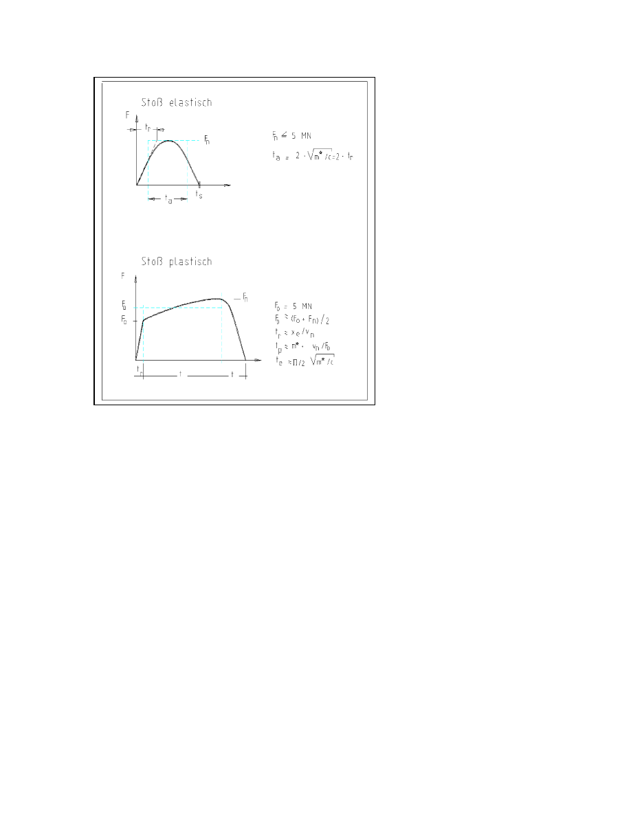
page 64
Draft prEN 1991-1-7:2003
Figure C.3: Load-time function for ship collision, respectively for elastic and plastic ship
response
with
t
r
= elastic elapsing time [s];
t
p
= plastic impact time [s];
t
e
= elastic response time [s];
t
a
= equivalent impact time [s];
t
s
= total impact time [s];
c = elastic stiffness of the ship = 60 MN/m;
F
0
= elastic-plastic limit force = 5 MN;
x
e
= elastic deformation
≈ 0,1 m;
v
n
= velocity of the colliding ship normal to the impact point :
- for frontal impact; v
n
= the sailing speed v
- for lateral impact, v
n
= v sin
α

page
65
Draft prEN 1991-1-7:2003
Annex D
(Informative)
Internal explosions
D1 Dust explosions in rooms and silos
see also background document, following text from ENV 1991-2-7
(1) The type of dust under normal circumstances may be considered by a material parameter K
st
,
which characterises the confined explosion behaviour. K
St
may be experimentally determined by
standard methods for each type of dust. A higher value for K
St
lead to higher pressures and
shorter rise times for internal explosion pressures. The value of K
St
depends on factors such as
changes in the chemical compositions, particle size and moisture content. The values for K
St
given in Table B.1 are examples.
NOTE: See ISO 1684-a Explosion Protection systems - Part 1: Determination of explosion
indices of combustible dusts in air.
(2) The venting area and the design pressure for dust explosions within a single silo may be
found from the following set of expressions:
v
Α
=
0.57
d
0.77
h/d
St
-5
/p
V
x
K
x
K
x
10
x
4.5
(D.1)
( )
( )
(
)
≤
≤
−
+
=
≤
≤
kN/m
00
2
p
150kN/m
for
1
kN/m
150
p
kN/m
20
for
ln
8
.
0
4
/
1
2
d
2
2
d
2
/
d
d
h
p
d
h
K
(D.2)
where:
ln (..) is the natural logarithm of (..);
A
ν
is the venting area, in square metres;
K
St
see Table B.1 (kN/m
2
x m/s
V
is the volume, in cubic metres;
p
d
is the design pressure, in kilonewton per square metres;
h
is the height of the silo cell, in metres;
d
is the diameter or equivalent diameter of silo cell, in metres.
Expressions (D.1) and (D.2) can be solved directly to determine the venting area, but only
iteratively to determine the design pressure.
Expressions (D.1) and (D.2) are valid for:
–
h/d
≤ 12;
–
static activation pressure of rupture disk p
a
≤ 0.10 kN/m
2
–
rupture disks and panels with a low mass which respond almost with no inertia.
(3) In dust explosions, pressures reach their maximum value within a time span in the order of
100 10
-6
s. Their decline to normal values strongly depends on the venting device and the
geometry of the enclosure.

page 66
Draft prEN 1991-1-7:2003
Table D.1 : K
St
values for dusts
Type of dust
K
St
(kN/m
2
x m/s
brown coal
18 000
cellulose
27 000
coffee
9 000
corn, corn crush
12 000
corn starch
21 000
grain
13 000
milk powder
16 000
mineral coal
13 000
mixed provender
4 000
paper
6 000
pea flour
14 000
pigment
29 000
rubber
14 000
rye flour, wheat flour
10 000
soya meal
12 000
sugar
15 000
washing powder
27 000
wood, wood flour
22 000
D2 Dust explosions in energy ducts
see background document
D3 Gas and vapour/air explosions in rooms, closed sewage bassins
see background document

page
67
Draft prEN 1991-1-7:2003
D4 Natural gas explosions
(3) The structure is designed to withstand the effects of an internal natural gas explosion using a
nominal equivalent static pressure given by:
p
d
= 1.5 p
v
(5.1)
or
p
d
= C m (A
tot
/A
v
)²
(5.2)
whichever is the greater,
where:
p
v
is the uniformly distributed static pressure at which venting components will fail, in
(kN/m²);
A
v
is the area of venting components, in m
2
;
A
tot
is the total surrounding area (ceiling, floor, walls), including the venting panels, in m
2
m
is the mass of the venting panels in kg/m
3
C
= 0.006 is a constant
NOTE : The value of C may be adjusted in the National Annex.
Where building components with different p
v
values contribute to the venting area, the largest
value of p
v
is to be used.
No value p
d
greater then 50 kN/m
2
need to be taken into account.
The ratio of the area of venting components and the volume are valid as in (5.3):
??
≤ A
v
/V
≤??
(5.3)
The expressions (5.1) and (5.2) are valid in a room up to ?? m³ total volume.
The explosive pressure acts effectively simultaneously on all of the bounding surfaces of the
room.
(5) Paragraphs 5.3.(3) and 5.3.(4) apply to buildings which have provision of natural gas or which
may have this provision in future, on the basis of which a natural gas explosion may be
considered the normative design accidental situation. For design of buildings where provision of
natural gas is totally impossible, a reduced value of the equivalent static pressure p
d
may be
appropriate. Key elements should have adequate robustness to resist other design accidental
situations, see Section 3.

page 68
Draft prEN 1991-1-7:2003
D5 Gas and vapour/air explosions in energy ducts
see background document
D6 Explosions in road and rail tunnels
(1
) In case of detonation, the following pressure time function should be taken into
account, see Figure D.1(a):
( )
1
2
1
0
1
c
¦
x
¦
-
¦
¦
c
¦
x
¦
for
/
c
¦
x
¦
-
t
-
exp
p
t
x,
p
0
c
x
t
t
≤
≤
=
(D.3)
( )
2
1
2
0
2
1
0
¦
x
¦
t
¦
¦
c
¦
x
¦
for
/
¦
¦
2
c
¦
x
¦
-
exp
p
t
x,
p
c
c
x
t
c
x
≤
≤
−
−
=
(D.4)
( )
conditions
other
all
for
0
t
x,
p
=
(D.5)
where:
p
o
is the peak pressure (=2 000 kN/m
2
)
C
1
is the progagaion velocity of the shock wave (
∼ 1 800 m/s);
C
2
is the acoustic propagation velocity in hot grasses (
∼ 800 m/s);
t
o
is the time constant (= 0.01 s);
is the height of the silo cell, in metres;
d
is the diameter or equivalent diameter of silo cell, in metres.
x
is the distance to the heart of the explosion;
t
is the time.
(2
) In case of deflagration the following pressure time characteristic should be
taken into account, see Figure D.1 (b):
( )
( )(
)
0
0
0
t
t
0
for
/
1
t/t0
4p
t
p
≤
≤
−
=
t
t
(D.4)
where:
p
o
is the peak pressure (=2 000 kN/m
2
)
t
o
is the time constant (= 0.01 s);
t
is the time.
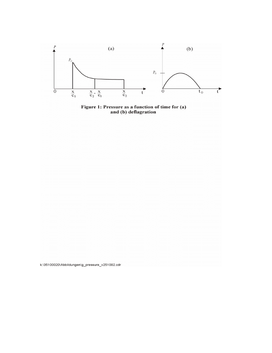
page
69
Draft prEN 1991-1-7:2003
This pressure holds for the entire interior surface of the tunnel.
Document Outline
- N391 prEN 1991-1-7 Stage 34 March 2003.pdf
- EUROPEAN STANDARD
- Foreword
- Section 1 General
- Section 2 Classification of actions
- Section 3 Design situations
- General
- Figure 3.1: Accidental Design Situations
- Section 4 Impact
- 4.1 Field of application
- Accidental actions caused by road vehicles
- 4.3.1 Impact on supporting substructures
- 4.4 Accidental actions caused by fork lift trucks
- 4.5 Accidental actions caused by derailed rail traffic under or adjacent to structures
- 4.5.1 Structures spanning across or alongside operational railway lines
- 4.7 Accidental actions caused by helicopters
- Section 5 Internal Explosions
- A1 Scope and field of application
- A2 Symbols
- A3 Introduction
- NOTE: Example of calculating the accidental design tensile force Ti in 6m span beam.
- A6.2 Load-bearing wall construction.
- Annex B
- Guidance for Risk Analysis
- B1 Introduction
- Annex D
- Internal explosions
- D1 Dust explosions in rooms and silos
- D2 Dust explosions in energy ducts
- D3 Gas and vapour/air explosions in rooms, closed sewage bassins
- D4 Natural gas explosions
- D5 Gas and vapour/air explosions in energy ducts
- D6 Explosions in road and rail tunnels
Wyszukiwarka
Podobne podstrony:
Eurocode 1 Part 1,3 prEN 1991 1 3 2003
Eurocode 1 Part 1,5 prEN 1991 1 5 2003
Eurocode 1 Part 1,6 prEN 1991 1 6 2004
Eurocode 1 Part 2 prEN 1991 2 2002
Eurocode 1 Part 1,2 prEN 1991 1 2 2002
Eurocode 1 Part 1,1 prEN 1991 1 1 2001
Eurocode 1 Part 3 prEN 1991 3 2002
Eurocode 8 Part 4 prEN 1998 4 2003 (12 2003)
Eurocode 1 Part 1,4 prEN 1991 1 4 2004
Eurocode 3 Part 1,9 PrEN 1993 1 9 2003
Eurocode 3 Part 1,8 prEN 1993 1 8 2003
Eurocode 1 Part 1,6 prEN 1991 1 6 2004
Eurocode 3 Part 1,9 PrEN 1993 1 9 2003
Eurocode 3 Part 1,8 prEN 1993 1 8 2003
Eurocode 8 Part 1 prEN 1998 1 (12 2003)
Eurocode 8 Part 5 prEn 1998 5 (12 2003)
Eurocode 8 Part 3 prEN 1998 3 (07 2003)
Eurocode 8 Part 1 prEN 1998 1 (12 2003)
więcej podobnych podstron