
EUROPEAN STANDARD
SU(1
NORME EUROPÉENNE
EUROPÄISCHE NORM
17 April 2003
UDC
Descriptors:
English version
Eurocode 3 : Design of steel structures
3DUW)DWLJXH
Calcul des structures en acier
Bemessung und Konstruktion von Stahlbauten
Partie 1.9 :
Teil 1.9 :
Fatigue
Ermüdung
6WDJHGUDIW
&(1
European Committee for Standardisation
Comité Européen de Normalisation
Europäisches Komitee für Normung
&HQWUDO6HFUHWDULDWUXHGH6WDVVDUW%%UXVVHOV
© 2003 Copyright reserved to all CEN members
Ref. No. EN 1993-1.9 : 2003. E

3DJH
Final draft
SU(1
17 April 2003
&RQWHQWV
3DJH
*HQHUDO
1.1 Scope
4
1.2 Definitions
4
1.2.1
General
4
1.2.2
Fatigue loading parameters
5
1.2.3
Fatigue strength
6
1.3 Symbols
7
%DVLFUHTXLUHPHQWVDQGPHWKRGV
$VVHVVPHQWPHWKRGV
6WUHVVHVIURPIDWLJXHDFWLRQV
&DOFXODWLRQRIVWUHVVHV
&DOFXODWLRQRIVWUHVVUDQJHV
6.1 General
11
6.2 Design value of nominal stress range
11
6.3 Design value of modified nominal stress range
11
6.4 Design value of stress range for welded joints of hollow sections
12
6.5 Design value of stress range for geometrical (hot spot) stress
12
)DWLJXHVWUHQJWK
7.1 General
12
7.2 Fatigue strength modifications
15
7.2.1
Non-welded or stress-relieved welded details in compression
15
7.2.2
Size effect
15
)DWLJXHYHULILFDWLRQ
$QQH[$>QRUPDWLYH@±'HWHUPLQDWLRQRIIDWLJXHORDGSDUDPHWHUVDQGYHULILFDWLRQIRUPDWV
A.1
Determination of loading events
27
A.2
Stress history at detail
27
A.3
Cycle counting
27
A.4
Stress range spectrum
27
A.5
Cycles to failure
27
A.6
Verification formats
28
$QQH[%>QRUPDWLYH@±)DWLJXHUHVLVWDQFHXVLQJWKHJHRPHWULFKRWVSRWVWUHVVPHWKRG

Final draft
3DJH
17 April 2003
SU(1
1DWLRQDODQQH[IRU(1
This standard gives alternative procedures, values and recommendations with notes indicating where national
choices may have to be made. The National Standard implementing EN 1993-1-9 should have a National
Annex containing all Nationally Determined Parameters for the design of steel structures to be constructed in
the relevant country.
National choice is allowed in EN 1993-1-9 through:
–
1.1(2)
–
2(2)
–
2(4)
–
3(2)
–
3(7)
–
5(2)
–
6.1(1)
–
6.2(2)
–
7.1(3)
–
7.1(5)
–
8(4)

3DJH
Final draft
SU(1
17 April 2003
*HQHUDO
6FRSH
(1)
EN 1993-1-9 gives methods for the assessment of fatigue resistance of members, connections and
joints subjected to fatigue loading.
(2)
These methods are derived from fatigue tests with large scale specimens, that include effects of
geometrical and structural imperfections from material production and execution (e.g. the effects of
tolerances and residual stresses from welding).
127( For tolerances see EN 1090. The choice of the execution standard may be given in the
National Annex, until such time as EN 1090 is published.
127( The National Annex may give supplementary information on inspection requirements
during fabrication.
(3)
The rules are applicable to structures where execution conforms with EN 1090.
127( Where appropriate, supplementary requirements are indicated in the detail category tables.
(4)
The assessment methods given in this part are applicable to all grades of structural steels, stainless
steels and unprotected weathering steels except where noted otherwise in the detail category tables. This part
only applies to materials which conform to the toughness requirements of EN 1993-1-10.
(5)
Fatigue assessment methods other than the
∆σ
R
-N methods as the notch strain method or fracture
mechanics methods are not covered by this part.
(6)
Post fabrication treatments to improve the fatigue strength other than stress relief are not covered in
this part.
(7)
The fatigue strengths given in this part apply to structures operating under normal atmospheric
conditions and with sufficient corrosion protection and regular maintenance. The effect of seawater corrosion
is not covered. Microstructural damage from high temperature (> 150 °C) is not covered.
'HILQLWLRQV
(1)
For the purpose of this European Standard the following definitions apply.
*HQHUDO
IDWLJXH
The process of initiation and propagation of cracks through a structural part due to action of fluctuating
stress.
QRPLQDOVWUHVV
A stress in the parent material or in a weld adjacent to a potential crack location calculated in accordance
with elastic theory excluding all stress concentration effects.
127( The nominal stress as specified in this part can be a direct stress, a shear stress, a principal
stress or an equivalent stress.

Final draft
3DJH
17 April 2003
SU(1
PRGLILHGQRPLQDOVWUHVV
A nominal stress multiplied by an appropriate stress concentration factor k
f
, to allow for a geometric
discontinuity that has not been taken into account in the classification of a particular constructional detail.
JHRPHWULFVWUHVV
hot spot stress
The maximum principal stress in the parent material adjacent to the weld toe, taking into account stress
concentration effects due to the overall geometry of a particular constructional detail.
127( Local stress concentration effects e.g. from the weld profile shape (which is already included
in the detail categories in Annex B) need not be considered.
UHVLGXDOVWUHVV
Residual stress is a permanent state of stress in a structure that is in static equilibrium and is independent of
any applied action. Residual stresses can arise from rolling stresses, cutting processes, welding shrinkage or
lack of fit between members or from any loading event that causes yielding of part of the structure.
)DWLJXHORDGLQJSDUDPHWHUV
ORDGLQJHYHQW
A defined loading sequence applied to the structure and giving rise to a stress history, which is normally
repeated a defined number of times in the life of the structure.
VWUHVVKLVWRU\
A record or a calculation of the stress variation at a particular point in a structure during a loading event.
UDLQIORZPHWKRG
Particular cycle counting method of producing a stress-range spectrum from a given stress history.
UHVHUYRLUPHWKRG
Particular cycle counting method of producing a stress-range spectrum from a given stress history.
127( For the mathematical determination see annex A.
VWUHVVUDQJH
The algebraic difference between the two extremes of a particular stress cycle derived from a stress history.
VWUHVVUDQJHVSHFWUXP
Histogram of the number of occurrences for all stress ranges of different magnitudes recorded or calculated
for a particular loading event.
GHVLJQVSHFWUXP
The total of all stress-range spectra in the design life of a structure relevant to the fatigue assessment.
GHVLJQOLIH
The reference period of time for which a structure is required to perform safely with an acceptable
probability that failure by fatigue cracking will not occur.

3DJH
Final draft
SU(1
17 April 2003
IDWLJXHOLIH
The predicted period of time to cause fatigue failure under the application of the design spectrum.
0LQHUVVXPPDWLRQ
A linear cumulative damage calculation based on the Palmgren-Miner rule.
HTXLYDOHQWFRQVWDQWDPSOLWXGHVWUHVVUDQJH
The constant-amplitude stress range that would result in the same fatigue life as for the design spectrum,
when the comparison is based on a Miner’s summation.
127( For the mathematical determination see Annex A.
IDWLJXHORDGLQJ
A set of action parameters based on typical loading events described by the positions of loads, their
magnitudes, frequencies of occurrence, sequence and relative phasing.
127( The fatigue actions in EN 1991 are upper bound values based on evaluations of
measurements of loading effects according to Annex A.
127( The action parameters as given in EN 1991 are either
–
Q
max
, n
max
, standardised spectrum or
–
max
n
E,
Q
related to n
max
or
–
Q
E,2
corresponding to n = 2
×10
6
cycles.
Dynamic effects are included in these parameters unless otherwise stated.
HTXLYDOHQWFRQVWDQWDPSOLWXGHIDWLJXHORDGLQJ
Simplified constant amplitude loading causing the same fatigue damage effects as a series of actual variable
amplitude loading events
)DWLJXHVWUHQJWK
IDWLJXHVWUHQJWKFXUYH
The quantitative relationship between the stress range and number of stress cycles to fatigue failure, used for
the fatigue assessment of a particular category of structural detail.
127( The fatigue strengths given in this part are lower bound values based on the evaluation of
fatigue tests with large scale test specimens in accordance with EN 1990 – Annex D.
GHWDLOFDWHJRU\
The numerical designation given to a particular detail for a given direction of stress fluctuation, in order to
indicate which fatigue strength curve is applicable for the fatigue assessment (The detail category number
indicates the reference fatigue strength
∆σ
C
in N/mm²).
FRQVWDQWDPSOLWXGHIDWLJXHOLPLW
The limiting direct or shear stress range value below which no fatigue damage will occur in tests under
constant amplitude stress conditions. Under variable amplitude conditions all stress ranges have to be below
this limit for no fatigue damage to occur.
Final draft
3DJH
17 April 2003
SU(1
FXWRIIOLPLW
Limit below which stress ranges of the design spectrum do not contribute to the calculated cumulative
damage.
HQGXUDQFH
The life to failure expressed in cycles, under the action of a constant amplitude stress history.
UHIHUHQFHIDWLJXHVWUHQJWK
The constant amplitude stress range
∆σ
C
, for a particular detail category for an endurance N = 2
×10
6
cycles
6\PEROV
stress range (direct stress)
stress range (shear stress)
E
E
equivalent constant amplitude stress range related to n
max
E,2
E,2
equivalent constant amplitude stress range related to 2 million cycles
C
C
reference value of the fatigue strength at N
C
= 2 million cycles
D
D
fatigue limit for constant amplitude stress ranges at the number of cycles N
D
L
L
cut-off limit for stress ranges at the number of cycle N
L
eq
equivalent stress range for connections in webs of orthotropic decks
C,red
reduced reference value of the fatigue strength
Ff
SDUWLDOIDFWRUIRUHTXLYDOHQWFRQVWDQWDPSOLWXGHVWUHVVUDQJHV
E
E
Mf
SDUWLDOIDFWRUIRUIDWLJXHVWUHQJWK
C
C
m
slope of fatigue strength curve
i
damage equivalent factors
ψ
1
factor for frequent value of a variable action
Q
k
characteristic value of a single variable action
k
s
reduction factor for fatigue stress to account for size effects
k
1
magnification factor for nominal stress ranges to account for secondary bending moments in
trusses
k
f
stress concentration factor
%DVLFUHTXLUHPHQWVDQGPHWKRGV
(1)
Structural members shall be designed for fatigue such that there is an acceptable level of probability
that their performance will be satisfactory throughout their design life.
127( Structures designed using fatigue actions from EN 1991 and fatigue resistance according to
this part are deemed to satisfy this requirement.
(2)
Annex A may be used to determine a specific loading model, if
–
no fatigue load model is available in EN 1991,
–
a more realistic fatigue load model is required.
127( Requirements for determining specific fatigue loading models may be specified in the
National Annex.

3DJH
Final draft
SU(1
17 April 2003
(3)
Fatigue tests may be carried out
–
to determine the fatigue strength for details not included in this part,
–
to determine the fatigue life of prototypes, for actual or for damage equivalent fatigue loads.
(4)
In performing and evaluating fatigue tests EN 1990 shall be taken into account (see also 7.1).
127( Requirements for determining fatigue strength from tests may be specified in the National
Annex.
(5)
The methods for the fatigue assessment given in this part follows the principle of design verification
by comparing action effects and fatigue strengths; such a comparison is only possible when fatigue actions
are determined with parameters of fatigue strengths contained in this standard.
(6)
Fatigue actions are determined according to the requirements of the fatigue assessment. They are
different from actions for ultimate limit state and serviceability limit state verifications.
127(Any fatigue cracks that develop during service life do not necessarily mean the end of the
service life. Cracks should be repaired with particular care for execution to avoid introducing more
severe notch conditions.
$VVHVVPHQWPHWKRGV
(1)
Fatigue assessment shall be undertaken using either:
–
damage tolerant method or
–
safe life method.
(2)
The damage tolerant method should provide an acceptable reliability that a structure will perform
satisfactorily for its design life, provided that a prescribed inspection and maintenance regime for detecting
and correcting fatigue damage is implemented throughout the design life of the structure.
127( The damage tolerant method may be applied when in the event of fatigue damage occurring
a load redistribution between components of structural elements can occur.
127( The National Annex may give provisions for inspection programmes.
127( Structures that are assessed to this part, the material of which is chosen according to
EN 1993-1-10 and which are subjected to regular maintenance are deemed to be damage tolerant.
(3)
The safe life method should provide an acceptable level of reliability that a structure will perform
satisfactorily for its design life without the need for regular in-service inspection for fatigue damage. The
safe life method should be applied in cases where local formation of cracks in one component could rapidly
lead to failure of the structural element or structure.
(4)
For the purpose of fatigue assessment using this part, an acceptable reliability level may be achieved
by adjustment of the partial factor for fatigue strength
γ
Mf
taking into account the consequences of failure and
the design assessment used.
(5)
Fatigue strengths are determined by considering the structural detail together with its metallurgical and
geometric notch effects. In the fatigue details presented in this part the probable site of crack initiation is also
indicated.
(6)
The assessment methods presented in this code use fatigue resistance in terms of fatigue strength
curves for
–
standard details applicable to nominal stresses
–
reference weld configurations applicable to geometric stresses.
Final draft
3DJH
17 April 2003
SU(1
(7)
The required reliability can be achieved as follows:
a) damage tolerant method
–
selecting details, materials and stress levels so that in the event of the formation of cracks a low rate of
crack propagation and a long critical crack length would result,
–
provision of multiple load path
–
provision of crack-arresting details,
–
provision of readily inspectable details during regular inspections.
b) safe-life method
–
VHOHFWLQJGHWDLOVDQGVWUHVVOHYHOVUHVXOWLQJLQDIDWLJXHOLIHVXIILFLHQWWRDFKLHYHWKH ±YDOXHVHTXDOWR
those for ultimate limit state verifications at the end of the design service life.
127(The National Annex may give the choice of the assessment method, definitions of classes of
FRQVHTXHQFHVDQGQXPHULFDOYDOXHVIRU
Mf
5HFRPPHQGHGYDOXHVIRU
Mf
are given in Table 3.1.
7DEOH5HFRPPHQGHGYDOXHVIRUSDUWLDOIDFWRUVIRUIDWLJXHVWUHQJWK
Consequence of failure
Assessment method
Low consequence
High consequence
Damage tolerant
1,00
1,15
Safe life
1,15
1,35
6WUHVVHVIURPIDWLJXHDFWLRQV
(1)
Modelling for nominal stresses shall take into account all action effects including distortional effects
and should be based on a linear elastic analysis for members and connections
(2)
For latticed girders made of hollow sections the modelling may be based on a simplified truss model
with pinned connections. Provided that the stresses due to external loading applied to members between
joints are taken into account the effects from secondary moments due to the stiffness of the connection can
be allowed for by the use of k
1
-factors (see Table 4.1 for circular sections, Table 4.2 for rectangular
sections).
7DEOHN
IDFWRUVIRUFLUFXODUKROORZVHFWLRQVXQGHULQSODQHORDGLQJ
Type of joint
Chords
Verticals
Diagonals
K type
1,5
1,0
1,3
Gap joints
N type / KT type
1,5
1,8
1,4
K type
1,5
1,0
1,2
Overlap joints
N type / KT type
1,5
1,65
1,25
7DEOHN
IDFWRUVIRUUHFWDQJXODUKROORZVHFWLRQVXQGHULQSODQHORDGLQJ
Type of joint
Chords
Verticals
Diagonals
K type
1,5
1,0
1,5
Gap joints
N type / KT type
1,5
2,2
1,6
K type
1,5
1,0
1,3
Overlap joints
N type / KT type
1,5
2,0
1,4
127( For the definition of joint types see EN 1993-1-8.
3DJH
Final draft
SU(1
17 April 2003
&DOFXODWLRQRIVWUHVVHV
(1)
Stresses shall be calculated at the serviceability limit state.
(2)
Class 4 cross sections are assessed for fatigue loads according to EN 1993-1-5
127( For guidance see EN 1993-2 to EN 1993-6.
127( The National Annex may give limitations for class 4 sections.
(3)
Nominal stresses should be calculated at the site of potential fatigue initiation. Effects producing stress
concentrations at details other than those included in Table 8.1 to Table 8.10 shall be accounted for by using
a stress concentration factor (SCF) according to 6.3 to give a modified nominal stress.
(4)
When using geometrical (hot spot) stress methods for details covered by Table B.1, the stresses shall
be calculated as shown in 6.5.
(5)
The relevant stresses for details in the parent material are
–
nominal direct stresses
σ
–
nominal shear stresses
τ
127( For effects of combined nominal stresses see 8(2).
(6)
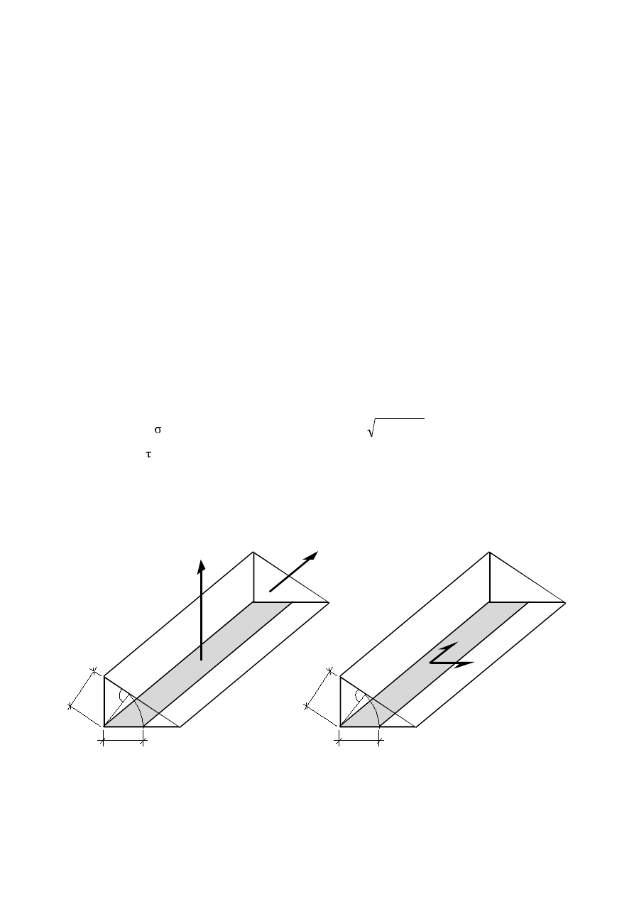
The relevant stresses in the welds are (see Figure 5.1)
–
QRUPDOVWUHVVHV
wf
transverse to the axis of the weld:
2
f
2
f
wf
⊥
⊥
τ
+
σ
=
σ
–
VKHDUVWUHVVHV
wf
longitudinal to the axis of the weld:
f
||
wf
τ
=
τ
for which two separate checks should be performed.
127( The above procedure differs from the procedure given for the verification of fillet welds for
the ultimate limit state, given in EN 1993-1-8.
.
a
a
z
F
f
II
F
f
.
a
a
z
J
f
II
J
f
relevant stresses
σ
f
relevant stresses
τ
f
)LJXUH5HOHYDQWVWUHVVHVLQWKHILOOHWZHOGV
Final draft
3DJH
17 April 2003
SU(1
&DOFXODWLRQRIVWUHVVUDQJHV
*HQHUDO
(1)
The fatigue assessment should be carried out using
–
nominal stress ranges for details shown in Table 8.1 to Table 8.10,
–
modified nominal stress ranges where abrupt changes of section occur close to the initiation site which
are not included in Table 8.1 to Table 8.10 or
–
geometric stress ranges where high stress gradients occur close to a weld toe in joints covered by
Table B.1
127( The National Annex may give information on the use of the nominal stress ranges, modified
nominal stress ranges or the geometric stress ranges. For detail categories for geometric stress ranges
see Annex B.
(2)
The design value of stress range to be used for the fatigue assessment should be the stress ranges
γ
Ff
(
,2
corresponding to N
C
= 2
×10
6
cycles.
'HVLJQYDOXHRIQRPLQDOVWUHVVUDQJH
(1)
The design value of nominal stress ranges
γ
Ff
E,2
and
γ
Ff
τ
E,2
should be determined as follows:
γ
Ff
E,2
1
×
2
×
i
× ... ×
n
× γ
Ff
Q
k
)
(6.1)
γ
Ff
τ
E,2
1
×
2
×
i
× ... ×
n
× τ(γ
Ff
Q
k
)
where
γ
Ff
Q
k
τ(γ
Ff
Q
k
) is the stress range caused by the fatigue loads specified in EN 1991
i
are damage equivalent factors depending on the spectra as specified in the relevant parts of EN
1993.
(2)
:KHUH QR DSSURSULDWH GDWD IRU
i
are available the design value of nominal stress range may be
determined using the principles in Annex A.
127( The National Annex may give informations supplementing Annex A.
'HVLJQYDOXHRIPRGLILHGQRPLQDOVWUHVVUDQJH
(1)
The design value of modified nominal stress ranges
γ
Ff
E,2
and
γ
Ff
τ
E,2
should be determined as
follows:
γ
Ff
E,2
= k
f
×
1
×
2
×
i
× ... ×
n
× γ
Ff
Q
k
)
(6.2)
γ
Ff
τ
E,2
= k
f
×
1
×
2
×
i
× ... ×
n
× τ(γ
Ff
Q
k
)
where k
f
is the stress concentration factor to take account of the local stress magnification in relation to
detail geometry not included in the reference
∆σ
R
-N-curve
127( k
f
-values may be taken from handbooks or from appropriate finite element calculations.

3DJH
Final draft
SU(1
17 April 2003
'HVLJQYDOXHRIVWUHVVUDQJHIRUZHOGHGMRLQWVRIKROORZVHFWLRQV
(1)
Unless more accurate calculations are carried out the design value of modified nominal stress range
γ
Ff
E,2
should be determined as follows using the simplified model in 4(2):
(
)
*
2
,
E
Ff
1
2
,
E
Ff
k
σ
∆
γ
=
σ
∆
γ
(6.3)
where
*
2
,
E
Ff
σ
∆
γ
is the design value of stress range calculated with a simplified truss model with pinned
joints
k
1
is the magnification factor according to Table 4.1 and Table 4.2.
'HVLJQYDOXHRIVWUHVVUDQJHIRUJHRPHWULFDOKRWVSRWVWUHVV
(1)
The design value of geometrical (hot spot) stress range
γ
Ff
E,2
should be determined as follows:
(
)
*
2
,
E
Ff
f
2
,
E
Ff
k
σ
∆
γ
=
σ
∆
γ
(6.4)
where k
f
is the stress concentration factor
)DWLJXHVWUHQJWK
*HQHUDO
(1)
The fatigue streng
WKIRUQRPLQDOVWUHVVHVLVUHSUHVHQWHGE\DVHULHVRIORJ
R
) – (log N) curves and
ORJ τ
R
) – (log N) curves (S-N-curves), which correspond to typical detail categories. Each detail category
is designated by a number which represents, in N/mm
2
WKH UHIHUHQFH YDOXH
C
DQG τ
C
for the fatigue
strength at 2 million cycles.
(2)
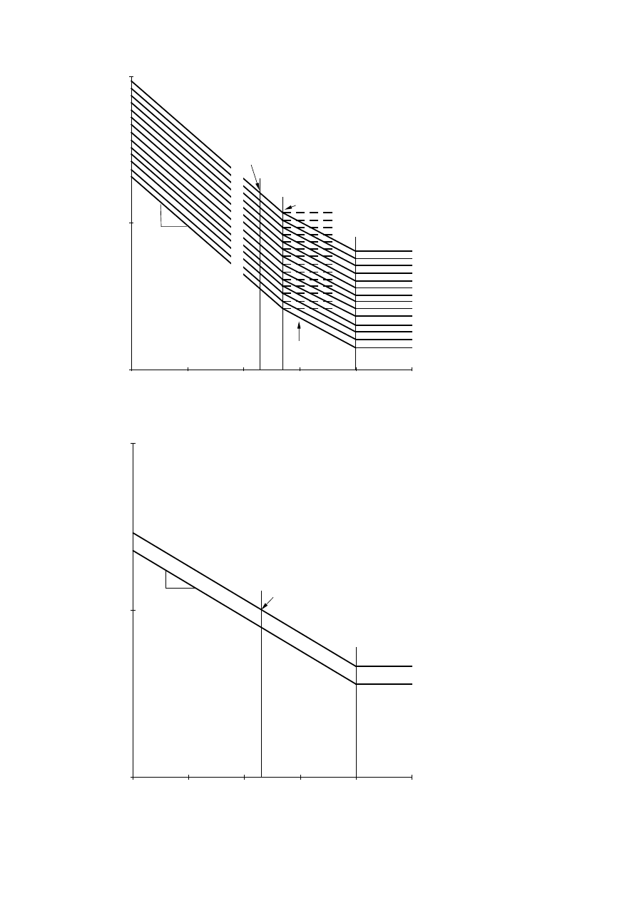
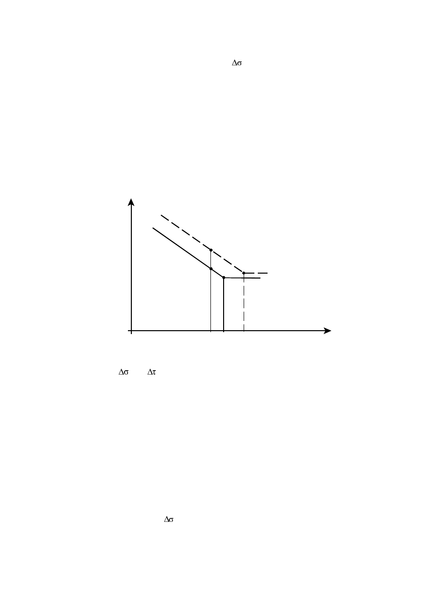
For constant amplitude nominal stresses as shown in Figure 7.1 and Figure 7.2 fatigue strengths can be
obtained as follows:
6
6
m
C
R
m
R
10
5
N
for
3
m
with
10
2
N
×
≤
=
×
σ
∆
=
σ
∆
, see Figure 7.1
8
6
m
C
R
m
R
10
N
for
5
m
with
10
2
N
≤
=
×
τ
∆
=
τ
∆
, see Figure 7.2
C
C
3
/
1
D
737
,
0
5
2
σ
∆
=
σ
∆
=
σ
∆
is the constant amplitude fatigue limit, see Figure 7.1, and
C
C
5
/
1
L
457
,
0
100
2
τ
∆
=
τ
∆
=
τ
∆
is the cut off limit, see Figure 7.2.
(3)
For nominal stress spectra with stress ranges above and below the constant amplitude fatigue limit
D
the fatigue strength should be based on the extended fatigue strength curves as follows:
8
R
6
6
m
D
R
m
R
6
6
m
C
R
m
R
10
N
10
5
for
5
m
with
10
5
N
10
5
N
for
3
m
with
10
2
N
≤
≤
×
=
×
σ
∆
=
σ
∆
×
≤
=
×
σ
∆
=
σ
∆
D
D
5
/
1
L
549
,
0
100
5
σ
∆
=
σ
∆
=
σ
∆
is the cut off limit, see Figure 7.1.
Final draft
3DJH
17 April 2003
SU(1
D
irec
t s
tr
ess
ran
g
e
∆σ
R
[N
/m
m
²]
10
100
1000
1,0E+04
1,0E+05
1,0E+06
1,0E+07
1,0E+08
1,0E+09
3
m = 3
1
m = 5
140
125
112
1
36
40
45
50
56
63
71
80
90
100
160
2
2
5
'HWDLOFDWHJRU\
∆σ
&
&RQVWDQWDPSOLWXGH
IDWLJXHOLPLW
∆σ
'
&XWRIIOLPLW
∆σ
/
Endurance, number of cycles N
)LJXUH)DWLJXHVWUHQJWKFXUYHVIRUGLUHFWVWUHVVUDQJHV
Shear st
res
s
ra
nge
∆τ
R
[N
/m
m
²]
10
100
1000
1,0E+04
1,0E+05
1,0E+06
1,0E+07
1,0E+08
1,0E+09
2
m = 5
1
100
80
1
2
'HWDLOFDWHJRU\
∆τ
&
&XWRIIOLPLW
∆τ
/
Endurance, number of cycles N
)LJXUH)DWLJXHVWUHQJWKFXUYHVIRUVKHDUVWUHVVUDQJHV
3DJH
Final draft
SU(1
17 April 2003
127( When test data were used to determine the appropriate detail category for a particular
FRQVWUXFWLRQDO GHWDLOWKH YDOXH RI WKH VWUHVVUDQJH
C
corresponding to a value of N
C
= 2 million
cycles were calculated for a 75% confidence level of 95% probability of survival for log N, taking into
account the standard deviation and the sample size and residual stress effects. The number of data
points (not lower than 10) was considered in the statistical analysis, see annex D of EN 1990.
127( The National Annex may permit the verification of a fatigue strength category for a
particular application provided that it is evaluated in accordance with NOTE 1.
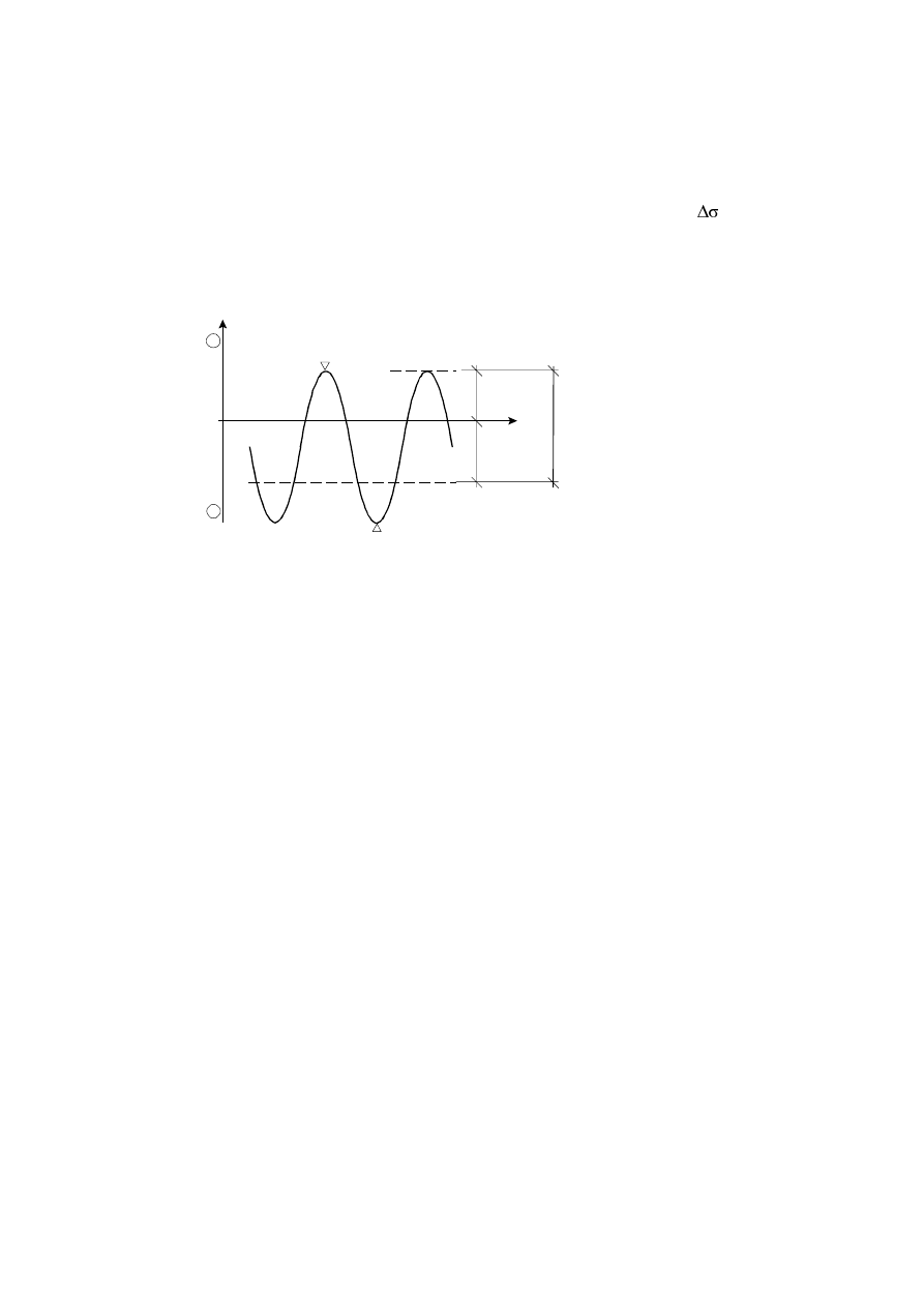
127( Test data for some details do not exactly fit the fatigue strength curves in Figure 7.1. In
order to ensure that non conservative conditions are avoided, such details, marked with an asterisk, are
located one detail category lower than their fatigue strength at 2
×10
6
cycles would require. An
alternative assessment may increase the classification of such details by one detail category provided
that the constant amplitude fatigue limit
∆σ
D
is defined as the fatigue strength at 10
7
cycles for m=3
(see Figure 7.3).
log
)F
R
5×10
6
10
7
2×10
6
)F
C
*
)F
C
)LJXUH$OWHUQDWLYHVWUHQJWK∆σ
&
IRUGHWDLOVFODVVLILHGDV∆σ
&
(4)
'HWDLOFDWHJRULHV
C
DQG
C
for nominal stresses are given in
Table 8.1 for plain members and mechanically fastened joints
Table 8.2 for welded built-up sections
Table 8.3 for transverse butt welds
Table 8.4 for weld attachments and stiffeners
Table 8.5 for load carrying welded joints
Table 8.6 for hollow sections
Table 8.7 for lattice girder node joints
Table 8.8 for orthotropic decks – closed stringers
Table 8.9 for orthotropic decks – open stringers
Table 8.10 for top flange to web junctions of runway beams
(5)
7KHIDWLJXHVWUHQJWKFDWHJRULHV
C
for geometric stress ranges are given in Annex B.
127( The National Annex may give fatigue strength categories ∆σ
C
and
∆τ
C
for details not covered
by Table 8.1 to Table 8.10 and by Annex B.
Final draft
3DJH
17 April 2003
SU(1
)DWLJXHVWUHQJWKPRGLILFDWLRQV
1RQZHOGHGRUVWUHVVUHOLHYHGZHOGHGGHWDLOVLQFRPSUHVVLRQ
(1)
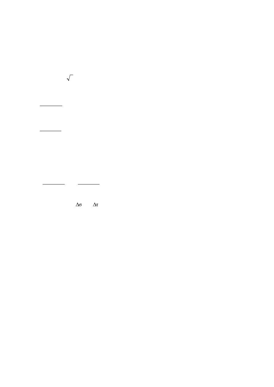
In non-welded details or stress-relieved welded details, the mean stress influence on the fatigue
VWUHQJWK PD\ EH WDNHQ LQWR DFFRXQW E\ GHWHUPLQLQJ D UHGXFHG HIIHFWLYH VWUHVV UDQJH
E,2
in the fatigue
assessment when part or all of the stress cycle is compressive.
(2)
The effective stress range may be calculated by adding the tensile portion of the stress range and 60%
of the magnitude of the compressive portion of the stress range, see Figure 7.4.
-
+
)F
= |
F
max
|+0,6 |
F
min
|
F
min
F
max
F
max
WHQVLRQ
± FRPSUHVVLRQ
)LJXUH0RGLILHGVWUHVVUDQJHIRUQRQZHOGHGRUVWUHVVUHOLHYHGGHWDLOV
6L]HHIIHFW
(1)
The size effect due to thickness or other dimensional effects should be taken into account as given in
Table 8.1 to Table 8.10. The fatigue strength then is given by:
C
s
red
,
C
k
σ
∆
=
σ
∆
(7.1)
3DJH
Final draft
SU(1
17 April 2003
)DWLJXHYHULILFDWLRQ
(1)
Nominal, modified nominal or geometric stress ranges due to frequent loads
ψ
1
Q
k
(see EN 1990) shall
not exceed
ranges
stress
shear
for
3
/
f
5
,
1
ranges
stress
direct
for
f
5
,
1
y
y
≤
τ
∆
≤
σ
∆
(8.1)
(2)
It shall be verified that under fatigue loading
0
,
1
/
Mf
C
2
,
E
Ff
≤
γ
σ
∆
σ
∆
γ
and
(8.2)
0
,
1
/
Mf
C
2
,
E
Ff
≤
γ
τ
∆
τ
∆
γ
127( Table 8.1 to Table 8.9 require stress ranges to be based on principal stresses for some details.
(3)
Unless otherwise stated in the fatigue strength categories in Table 8.8 and Table 8.9, in the case of
combined stress ranges
∆σ
E,2
and
∆τ
E,2
it shall be verified that:
0
,
1
/
/
5
Mf
C
2
,
E
Ff
3
Mf
C
2
,
E
Ff
≤
γ
τ
∆
τ
∆
γ
+
γ
σ
∆
σ
∆
γ
(8.3)
(4)
:KHQQRGDWDIRU
E,2
RU
E,2
are available the verification format in Annex A may be used.
127( The National Annex may give information on the use of Annex A.
Final draft
3DJH
17 April 2003
SU(1
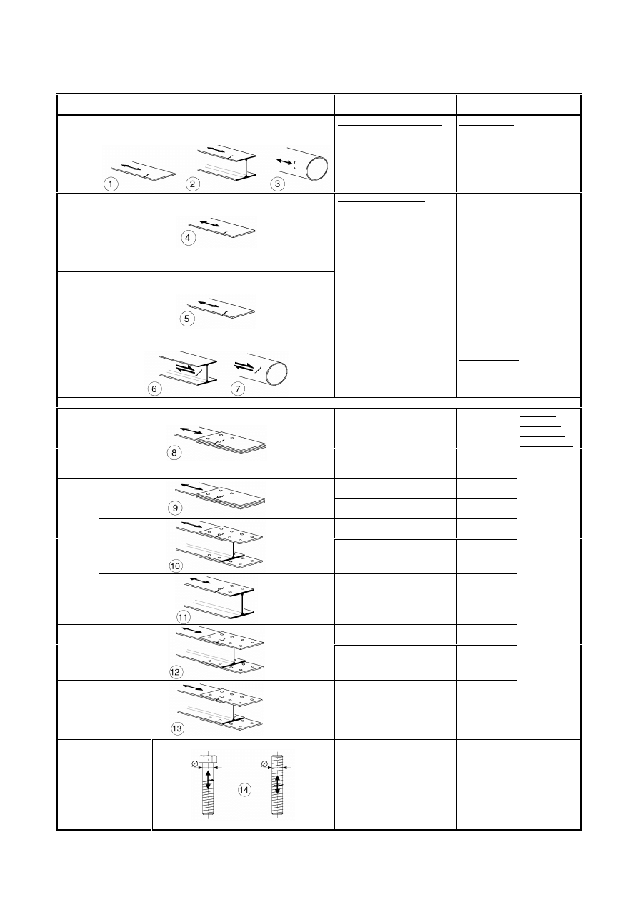
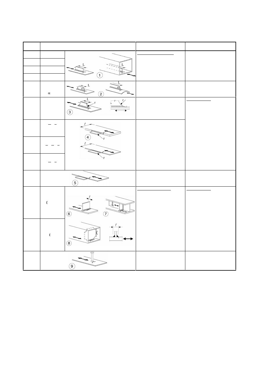
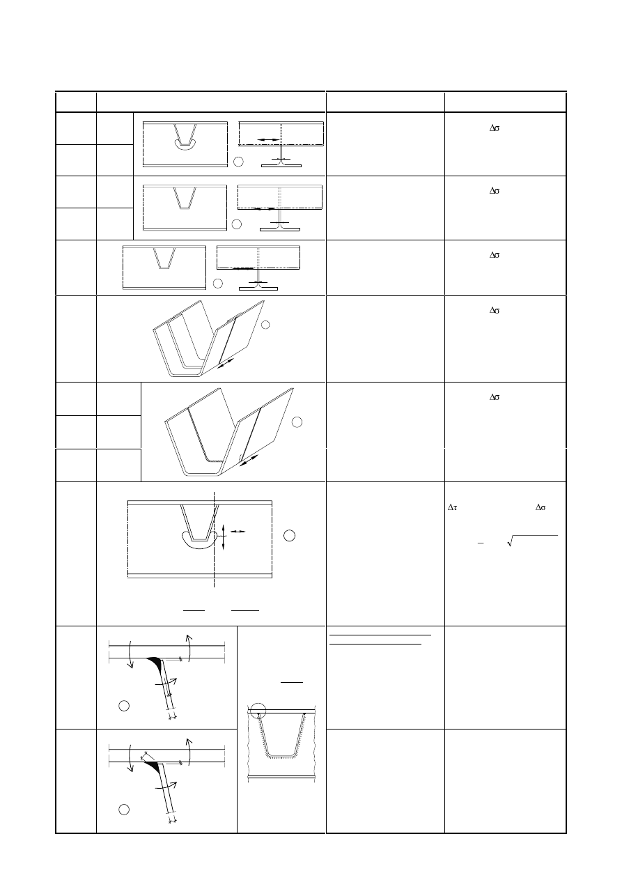
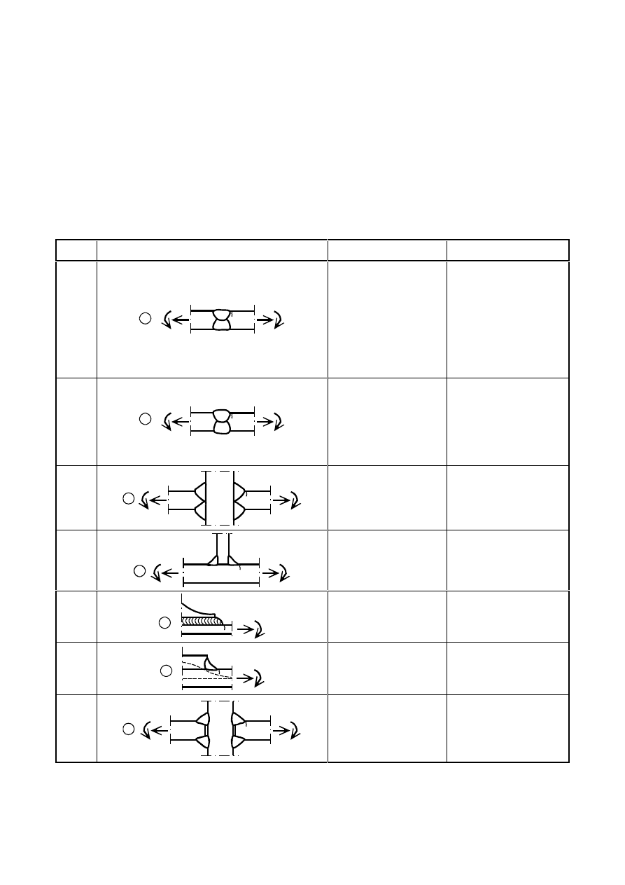
7DEOH3ODLQPHPEHUVDQGPHFKDQLFDOO\IDVWHQHGMRLQWV
Detail
category
Constructional detail
Description
Requirements
160
127( The fatigue strength curve associated with category 160
is the highest. No detail can reach a better fatigue strength at any
number of cycles.
Rolled and extruded products:
1) Plates and flats;
2) Rolled sections;
3) Seamless hollow sections,
either rectangular or circular.
Details 1) to 3):
Sharp edges, surface and rolling
flaws to be improved by grinding
until removed and smooth
transition achieved.
140
125
Sheared or gas cut plates:
4) Machine gas cut or sheared
material with subsequent
dressing.
5) Material with machine gas cut
edges having shallow and
regular drag lines or manual gas
cut material, subsequently
dressed to remove all edge
discontinuities.
Machine gas cut with cut quality
according to EN 1090.
4) All visible signs of edge
discontinuities to be removed.
The cut areas are to be machined
or ground and all burrs to be
removed.
Any machinery scratches for
example from grinding
operations, can only be parallel to
the stresses.
Details 4) and 5):
-
Re-entrant corners to be
improved by grinding (slope
¼) or evaluated using the
appropriate stress concentration
factors.
-
No repair by weld refill.
100
m = 5
6) and 7)
Rolled and extruded products as
in details 1), 2), 3)
Details 6) and 7):
∆τ calculated from:
t
I
)
t
(
S
V
=
τ
For detail 1 – 5 made of weathering steel use the next lower category.
8) Double covered symmetrical
joint with preloaded high
strength bolts.
8)
∆σ to be
calculated on
the gross
cross-section.
112
8) Double covered symmetrical
joint with preloaded injection
bolts.
8) ... gross
cross-section.
9) Double covered joint with
fitted bolts.
9) ... net cross-
section.
9) Double covered joint with
non preloaded injection bolts.
9) ... net cross-
section.
10) One sided connection with
preloaded high strength bolts.
10) ... gross
cross-section.
10) One sided connection with
preloaded injection bolts.
10) ... gross
cross-section.
90
11) Structural element with
holes subject to bending and
axial forces
11) ... net
cross-section.
12) One sided connection with
fitted bolts.
12) ... net
cross-section.
80
12) One sided connection with
non-preloaded injection bolts.
12) ... net
cross-section.
50
13) One sided or double covered
symmetrical connection with
non-preloaded bolts in normal
clearance holes.
No load reversals.
13) ... net
cross-section.
For bolted
connections
(Details 8) to
13)) in general:
End distance:
e
1
G
Edge distance:
e
2
G
Spacing:
p
1
G
Spacing:
p
2
G
Detailing to
EN 1993-1-8,
Figure 3.1
50
size effect
for
i > 30mm:
k
s
=(30/
i)
0,25
14) Bolts and rods with rolled or
cut threads in tension.
For large diameters (anchor
bolts) the size effect has to be
taken into account with k
s
.
14)
∆σ to be calculated using the
tensile stress area of the bolt.
Bending and tension resulting
from prying effects and bending
stresses from other sources must
be taken into account.
For preloaded bolts, the reduction
of the stress range may be taken
into account.
3DJH
Final draft
SU(1
17 April 2003
7DEOHFRQWLQXHG1RQZHOGHGGHWDLOV
Detail
category
Constructional detail
Description
Requirements
100
m=5
Bolts in single or double shear
Thread not in the shear plane
15)
-
Fitted bolts
-
normal bolts without load
reversal (bolts of grade 5.6, 8.8
or 10.9)
15)
∆τ calculated on the shank area of
the bolt.
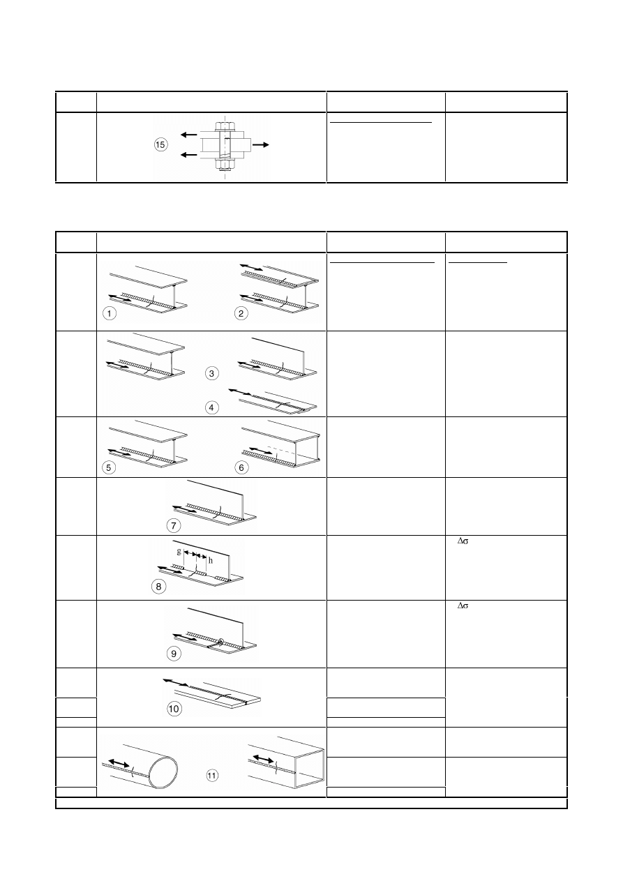
7DEOH:HOGHGEXLOWXSVHFWLRQV
Detail
category
Constructional detail
Description
Requirements
125
Continuous longitudinal welds:
1) Automatic butt welds carried
out from both sides.
2) Automatic fillet welds. Cover
plate ends to be checked using
detail 6) or 7) in Table 8.5.
Details 1) and 2):
No stop/start position is permitted
except when the repair is
performed by a specialist and
inspection is carried out to verify
the proper execution of the repair.
112
3) Automatic fillet or butt weld
carried out from both sides but
containing stop/start positions.
4) Automatic butt welds made
from one side only, with a
continuous backing bar, but
without stop/start positions.
4) When this detail contains
stop/start positions category 100
to be used.
100
5) Manual fillet or butt weld.
6) Manual or automatic butt
welds carried out from one side
only, particularly for box girders
5), 6) A very good fit between the
flange and web plates is essential.
The web edge to be prepared such
that the root face is adequate for
the achievement of regular root
penetration without break-out.
100
7) Repaired automatic or manual
fillet or butt welds for categories
1) to 6).
7) Improvement by grinding
performed by specialist to remove
all visible signs and adequate
verification can restore the
original category.
80
g/h
8) Intermittent longitudinal fillet
welds.
EDVHGRQGLUHFWVWUHVVLQ
flange.
71
9) Longitudinal butt weld, fillet
weld or intermittent weld with a
cope hole height not greater than
60 mm.
For cope holes with a height
> 60 mm see detail 1) in Table
8.4
EDVHGRQGLUHFWVWUHVVLQ
flange.
125
10) Longitudinal butt weld, both
sides ground flush parallel to
load direction, 100% NDT
112
10) No grinding and no
start/stop
90
10) with start/stop positions
140
11) Automatic longitudinal seam
weld without stop/start positions
in hollow sections
11) Free from defects outside the
tolerances of EN 1090.
Wall thickness t
≤ 12,5 mm.
125
11) Automatic longitudinal seam
weld without stop/start positions
in hollow sections
90
11) with stop/start positions
11) Wall thickness t > 12,5 mm.
For details 1 to 11 made with fully mechanized welding the categories for automatic welding apply.
Final draft
3DJH
17 April 2003
SU(1
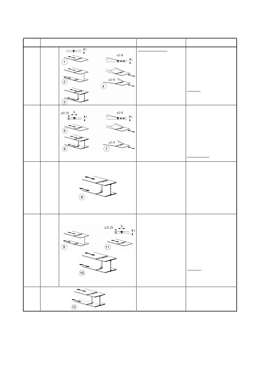
7DEOH7UDQVYHUVHEXWWZHOGV
Detail
category
Constructional detail
Description
Requirements
112
size effect
for
t>25mm:
k
s
=(25/t)
0,2
Without backing bar:
1) Transverse splices in plates
and flats.
2) Flange and web splices in
plate girders before assembly.
3) Full cross-section butt welds
of rolled sections without cope
holes.
4) Transverse splices in plates or
flats tapered in width or in
thickness, with a slope
¼.
-
All welds ground flush to plate
surface parallel to direction of
the arrow.
-
Weld run-on and run-off pieces
to be used and subsequently
removed, plate edges to be
ground flush in direction of
stress.
-
Welded from both sides;
checked by NDT.
Detail 3):
Applies only to joints of rolled
sections, cut and rewelded.
90
size effect
for
t>25mm:
k
s
=(25/t)
0,2
5) Transverse splices in plates or
flats.
6) Full cross-section butt welds
of rolled sections without cope
holes.
7) Transverse splices in plates or
flats tapered in width or in
thickness with a slope
¼.
Translation of welds to be
machined notch free.
-
The height of the weld convexity
to be not greater than 10% of the
weld width, with smooth
transition to the plate surface.
-
Weld run-on and run-off pieces
to be used and subsequently
removed, plate edges to be
ground flush in direction of
stress.
-
Welded from both sides;
checked by NDT.
Details 5 and 7:
Welds made in flat position.
90
size effect
for
t>25mm:
k
s
=(25/t)
0,2
8) As detail 3) but with cope
holes.
-
All welds ground flush to plate
surface parallel to direction of
the arrow.
-
Weld run-on and run-off pieces
to be used and subsequently
removed, plate edges to be
ground flush in direction of
stress.
-
Welded from both sides;
checked by NDT.
-
Rolled sections with the same
dimensions without tolerance
differences
80
size effect
for
t>25mm:
k
s
=(25/t)
0,2
9) Transverse splices in welded
plate girders without cope hole.
10) Full cross-section butt welds
of rolled sections with cope
holes.
11) Transverse splices in plates,
flats, rolled sections or plate
girders.
-
The height of the weld convexity
to be not greater than 20% of the
weld width, with smooth
transition to the plate surface.
-
Weld not ground flush
-
Weld run-on and run-off pieces
to be used and subsequently
removed, plate edges to be
ground flush in direction of
stress.
-
Welded from both sides;
checked by NDT.
Detail 10:
The height of the weld convexity
to be not greater than 10% of the
weld width, with smooth
transition to the plate surface.
63
12) Full cross-section butt welds
of rolled sections without cope
hole.
-
Weld run-on and run-off pieces
to be used and subsequently
removed, plate edges to be
ground flush in direction of
stress.
-
Welded from both sides.
3DJH
Final draft
SU(1
17 April 2003
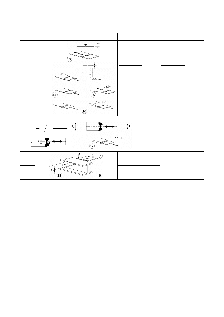
7DEOHFRQWLQXHG7UDQVYHUVHEXWWZHOGV
Detail
category
Constructional detail
Description
Requirements
36
13) Butt welds made from one
side only.
71
size effect
for
t>25mm:
k
s
=(25/t)
0,2
13) Butt welds made from one
side only when full penetration
checked by appropriate NDT.
13) Without backing strip.
71
size effect
for
t>25mm:
k
s
=(25/t)
0,2
With backing strip:
14) Transverse splice.
15) Transverse butt weld
tapered in width or thickness
with a slope
¼.
Also valid for curved plates.
Details 14) and 15):
Fillet welds attaching the backing
strip to terminate
PPIURP
the edges of the stressed plate.
Tack welds inside the shape of
butt welds.
50
size effect
for
t>25mm:
k
s
=(25/t)
0,2
16) Transverse butt weld on a
permanent backing strip tapered
in width or thickness with a
slope
¼.
Also valid for curved plates.
16) Where backing strip fillet
welds end < 10 mm from the
plate edge, or if a good fit cannot
be guaranteed.
71
size effect for t>25mm and/or
generalisation for eccentricity:
+
+
=
5
,
1
2
5
,
1
1
5
,
1
1
1
2
,
0
1
s
t
t
t
t
e
6
1
t
25
k
t
2
≥ t
1
slope
≤ 1/2
17) Transverse butt
weld, different
thicknesses without
transition,
centrelines aligned.
As
detail 1
in
Table 8.5
18) Transverse butt weld at
intersecting flanges.
As
detail 4
in
Table 8.4
19) With transition radius
according to Table 8.4, detail 4
Details 18) and 19)
The fatigue strength of the
continuous component has to be
checked with Table 8.4, detail 4
or detail 5.
Final draft
3DJH
17 April 2003
SU(1
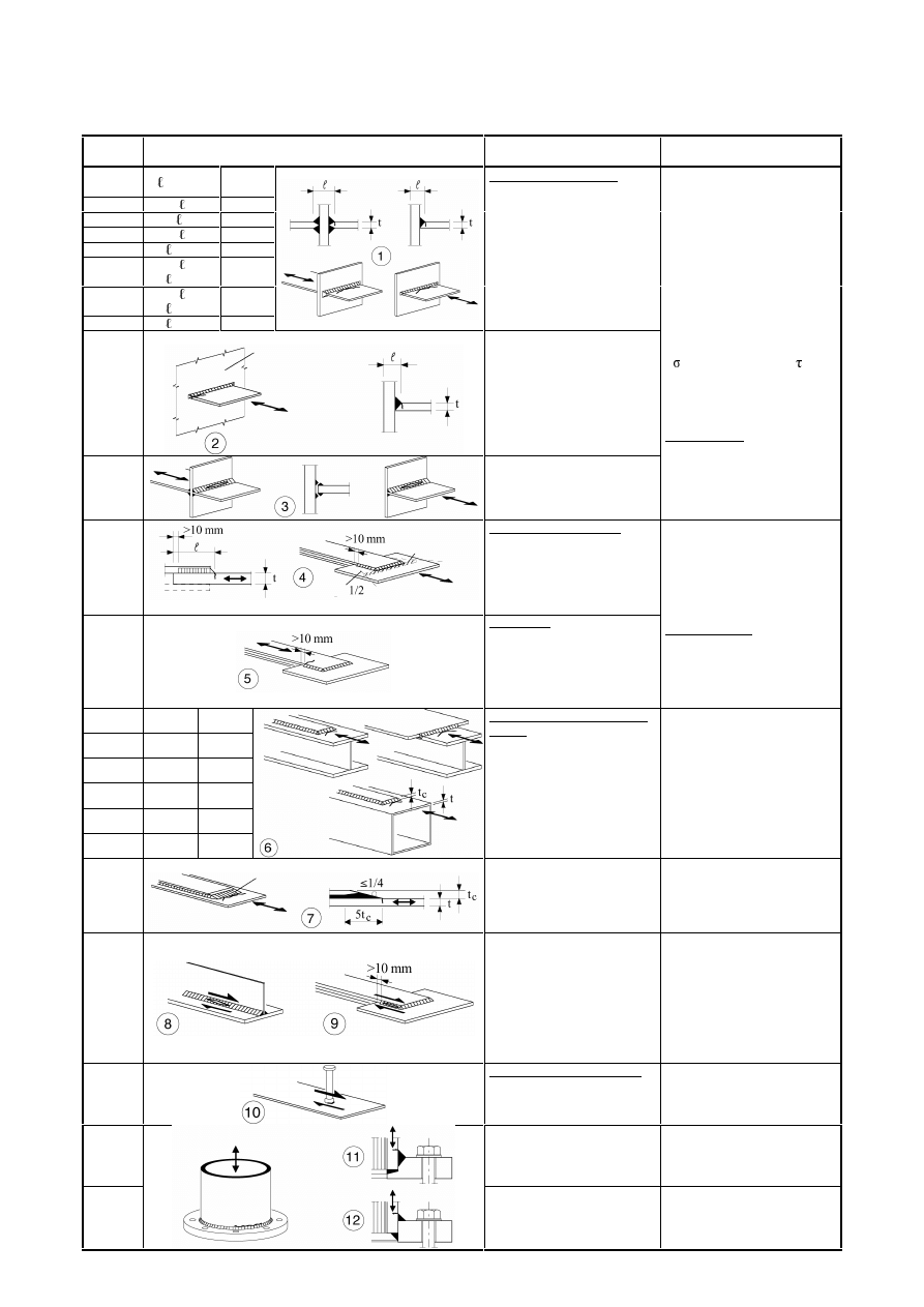
7DEOH:HOGDWWDFKPHQWVDQGVWLIIHQHUV
Detail
category
Constructional detail
Description
Requirements
80
L
PP
71
50<L
PP
63
80<L
PP
56
L>100mm
Longitudinal attachments:
1) The detail category varies
according to the length of the
attachment L.
The thickness of the attachment
must be less than its height. If not
see Table 8.5, details 5 or 6.
71
L>100mm
2) Longitudinal attachments to
plate or tube.
80
r>150mm
reinforced
3) Longitudinal fillet welded
gusset with radius transition to
plate or tube; end of fillet weld
reinforced (full penetration);
length of reinforced weld > r.
90
3
1
L
r ≥
or
r>150mm
71
3
1
L
r
6
1
≤
≤
50
6
1
L
r <
L: attachment length as above
4) Gusset plate, welded to the
edge of a plate or beam flange.
Details 3) and 4):
Smooth transition radius r formed
by initially machining or gas
cutting the gusset plate before
welding, then subsequently
grinding the weld area parallel to
the direction of the arrow so that
the transverse weld toe is fully
removed.
40
5) As welded, no radius
transition.
80
PP
71
50<
PP
Transverse attachments:
6) Welded to plate.
7) Vertical stiffeners welded to a
beam or plate girder.
8) Diaphragm of box girders
welded to the flange or the web.
May not be possible for small
hollow sections.
The values are also valid for ring
stiffeners.
Details 6) and 7):
Ends of welds to be carefully
ground to remove any undercut
that may be present.
7)
∆σ to be calculated using
principal stresses if the stiffener
terminates in the web, see left
side.
80
9) The effect of welded shear
studs on base material.
3DJH
Final draft
SU(1
17 April 2003
7DEOH/RDGFDUU\LQJZHOGHGMRLQWV
Detail
category
Constructional detail
Description
Requirements
80
PP
all t
[mm]
71
50<
all t
63
80<
all t
56
100<
all t
56
!
t
50
120<
!
t>20
20<t
45
200<
!
t>30
30<t
40
!
t>50
Cruciform and Tee joints:
1) Toe failure in full penetration
butt welds and all partial
penetration joints.
As
detail 1
in
Table 8.5
flexible panel
2) Toe failure from edge of
attachment to plate, with stress
peaks at weld ends due to local
plate deformations.
36*
3) Root failure in partial
penetration Tee-butt joints or
fillet welded joint and effective
full penetration in Tee-butt joint.
1) Inspected and found free from
discontinuities and misalignments
outside the tolerances of
EN 1090.
2) For computing
∆σ, use
modified nominal stress.
3) In partial penetration joints two
fatigue assessments are required.
Firstly, root cracking evaluated
according to stresses defined in
section 5, using category 36* for
∆
w
and category 80 for
∆
w
.
Secondly, toe cracking is
evaluated by determining
∆σ in
the load-carrying plate.
Details 1) to 3):
The misalignment of the load-
carrying plates should not exceed
15 % of the thickness of the
intermediate plate.
As
detail 1
in
Table 8.5
stressed area of main panel: slope = 1/2
Overlapped welded joints:
4) Fillet welded lap joint.
45*
Overlapped:
5) Fillet welded lap joint.
4)
∆σ in the main plate to be
calculated on the basis of area
shown in the sketch.
5)
∆σ to be calculated in the
overlapping plates.
Details 4) and 5):
-
Weld terminations more than 10
mm from plate edge.
-
Shear cracking in the weld
should be checked using detail
8).
t
c
<t
t
c
W
56*
t
-
50
20<t
t
45
30<t
20<t
40
t>50
30<t
36
-
t>50
Cover plates in beams and plate
girders:
6) End zones of single or
multiple welded cover plates,
with or without transverse end
weld.
6) If the cover plate is wider than
the flange, a transverse end weld
is needed. This weld should be
carefully ground to remove
undercut.
The minimum length of the cover
plate is 300 mm. For shorter
attachments size effect see detail
1).
56
reinforced transverse end weld
7) Cover plates in beams and
plate girders.
5t
c
is the minimum length of the
reinforcement weld.
7) Transverse end weld ground
flush. In addition, if t
c
>20mm,
front of plate at the end ground
with a slope < 1 in 4.
80
m=5
8) Continuous fillet welds
transmitting a shear flow, such
as web to flange welds in plate
girders.
9) Fillet welded lap joint.
8)
∆τ to be calculated from the
weld throat area.
9)
∆τ to be calculated from the
weld throat area considering the
total length of the weld. Weld
terminations more than 10 mm
from the plate edge, see also 4)
and 5) above.
see EN
1994-2
(90
m=8)
Welded stud shear connectors:
10) For composite application
10)
∆τ to be calculated from the
nominal cross section of the stud.
71
11) Tube socket joint with 80%
full penetration butt welds.
11) Weld toe ground.
∆σ
computed in tube.
40
12) Tube socket joint with fillet
welds.
12)
∆σ computed in tube.
Final draft
3DJH
17 April 2003
SU(1
7DEOH+ROORZVHFWLRQVWPP
Detail
category
Constructional detail
Description
Requirements
71
1) Tube-plate joint, tubes flatted,
butt weld (X-groove)
1)
∆σ computed in tube.
Only valid for tube diameter less
than 200 mm.
71
63
!
2) Tube-plate joint, tube slitted
and welded to plate. Holes at
end of slit.
2)
∆σ computed in tube.
Shear cracking in the weld should
be verified using Table 8.5, detail
8).
71
3
Transverse butt welds:
3) Butt-welded end-to-end
connections between circular
structural hollow sections.
56
4
4) Butt-welded end-to-end
connections between rectangular
structural hollow sections.
Details 3) and 4):
-
Weld convexity
RIZHOG
width, with smooth transitions.
-
Welded in flat position,
inspected and found free from
defects outside the tolerances
EN 1090.
-
Classify 2 detail categories
higher if t > 8 mm.
71
5
1 0 0 m m
1 0 0 m m
R
R
Welded attachments:
5) Circular or rectangular
structural hollow section, fillet-
welded to another section.
5)
-
Non load-carrying welds.
-
Width parallel to stress direction
PP
-
Other cases see Table 8.4.
50
Welded splices:
6) Circular structural hollow
sections, butt-welded end-to-end
with an intermediate plate.
45
7) Rectangular structural hollow
sections, butt welded end-to-end
with an intermediate plate.
Details 6) and 7):
-
Load-carrying welds.
-
Welds inspected and found free
from defects outside the
tolerances of EN 1090.
-
Classify 1 detail category higher
if t > 8 mm.
40
8) Circular structural hollow
sections, fillet-welded end-to-
end with an intermediate plate.
36
9) Rectangular structural hollow
sections, fillet-welded end-to-
end with an intermediate plate.
Details 8) and 9):
-
Load-carrying welds.
-
Wall thickness t
PP
3DJH
Final draft
SU(1
17 April 2003
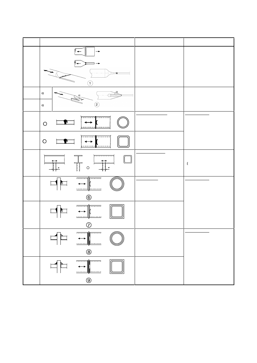
7DEOH/DWWLFHJLUGHUQRGHMRLQWV
Detail
category
Constructional detail
Requirements
90
m=5
0
,
2
t
t
i
0
≥
45
m=5
0
,
1
t
t
i
0
=
Gap joints: Detail 1): K and N joints, circular structural hollow sections:
Θ
Θ
t
i
d
i
t
0
0
d
1
+e
i/p
g
71
m=5
0
,
2
t
t
i
0
≥
36
m=5
0
,
1
t
t
i
0
=
Gap joints: Detail 2): K and N joints, rectangular structural hollow sections:
Θ
Θ
t
i
b
i
t
0
0
b
2
h
0
g
+e
i/p
Details 1) and 2):
-
Separate assessments needed
for the chords and the braces.
-
For intermediate values of the
ratio t
o
/t
i
interpolate linearly
between detail categories.
-
Fillet welds permitted for
braces with wall thickness t
8 mm.
-
t
0
and t
i
PP
-
35°
-
b
0
/t
0
×t
0
/t
i
-
d
0
/t
0
×t
0
/t
i
-
0,4
E
i
/b
0
-
0,25
G
i
/d
0
-
b
0
PP
-
d
0
PP
-
- 0,5h
0
H
i/p
K
0
-
- 0,5d
0
H
i/p
G
0
-
e
o/p
E
0
or
G
0
[e
o/p
is out-of-plane eccentricity]
Detail 2):
0,5(b
o
- b
i
)
JE
o
- b
i
)
and g
W
o
71
m=5
4
,
1
t
t
i
0
≥
56
m=5
0
,
1
t
t
i
0
=
Overlap joints: Detail 3): K joints, circular or rectangular structural hollow sections:
b
i
t
i
d
i
t
0
0
d
0
b
h
0
3
Θ
Θ
-e
i/p
71
m=5
4
,
1
t
t
i
0
≥
50
m=5
0
,
1
t
t
i
0
=
Overlap joints: Detail 4): N joints, circular or rectangular structural hollow sections:
b
i
t
i
d
i
t
0
0
d
0
b
h
0
4
Θ
-e
i/p
Details 3) and 4):
-
30 %
RYHUODS
-
overlap = (q/p) × 100 %
-
Separate assessments needed
for the chords and the braces.
-
For intermediate values of the
ratio t
o
/t
i
interpolate linearly
between detail categories.
-
Fillet welds permitted for
braces with wall thickness t
8 mm.
-
t
0
and t
i
PP
-
35°
-
b
0
/t
0
×t
0
/t
i
-
d
0
/t
0
×t
0
/t
i
-
0,4
E
i
/b
0
-
0,25
G
i
/d
0
-
b
0
PP
-
d
0
PP
-
- 0,5h
0
H
i/p
K
0
-
- 0,5d
0
H
i/p
G
0
-
e
o/p
E
0
or
G
0
[e
o/p
is out-of-plane eccentricity]
Definition of p and q:
Final draft
3DJH
17 April 2003
SU(1
7DEOH2UWKRWURSLFGHFNV±FORVHGVWULQJHUV
Detail
category
Constructional detail
Description
Requirements
80
t
PP
71
t>12mm
σ
∆
1
t
1) Continuous longitudinal
stringer, with additional cutout
in cross girder.
1) Assessment based on the direct
VWUHVVUDQJH LQWKHORQJLWXGLQDO
stringer.
80
t
PP
71
t>12mm
σ
∆
2
t
2) Continuous longitudinal
stringer, no additional cutout in
cross girder.
2) Assessment based on the direct
VWUHVVUDQJH LQWKHVWULQJHU
36
σ
∆
3
t
3) Separate longitudinal stringer
each side of the cross girder.
3) Assessment based on the direct
VWUHVVUDQJH LQWKHVWULQJHU
71
∆
σ
4
4) Joint in rib, full penetration
butt weld with steel backing
plate.
4) Assessment based on the direct
VWUHVVUDQJH LQWKHVWULQJHU
112
As detail
1, 2, 4 in
Table 8.3
90
As detail
5, 7 in
Table 8.3
80
As detail
9, 11 in
Table 8.3
∆
σ
5
5) Full penetration butt weld in
rib, welded from both sides,
without backing plate.
5) Assessment based on the direct
VWUHVVUDQJH LQWKHVWULQJHU
Tack welds inside the shape of
butt welds.
36
τ
s
σ
∆
∆
6
s
,
net
s
W
M
∆
=
σ
∆
s
,
net
,
w
s
A
V
∆
=
τ
∆
6) Connection of continuous
longitudinal rib to cross girder.
6) Assessment based on
∆σ
eq
combining the shear stress range
DQGGLUHFWVWUHVVUDQJH LQ
the web, as an equivalent stress
range:
(
)
2
2
eq
4
2
1
τ
∆
+
σ
∆
+
σ
∆
=
σ
∆
71
mm
2
≤
mm
2
≤
W
O
U
Z
0
0
0
W
D
≥
7
Weld connecting deck plate to
trapezoidal or V-section rib
7) Partial penetration weld with
a
≥ t
7) Assessment based on direct
stress range from bending in the
plate.
50
W
O
U
Z
0
0
0
D
mm
5
.
0
≤
8
fillet weld
w
w
W
M
∆
=
σ
∆
8) Fillet weld or partial
penetration welds out of the
range of detail 7)
8) Assessment based on direct
stress range from bending in the
plate.
3DJH
Final draft
SU(1
17 April 2003
7DEOH2UWKRWURSLFGHFNV±RSHQVWULQJHUV
Detail
category
Constructional detail
Description
Requirements
80
t
PP
71
t>12mm
t
∆
σ
1
1) Connection of continuous
longitudinal stringer to cross
girder.
1) Assessment based on the direct
VWUHVVUDQJH LQWKHVWULQJHU
56
∆
∆
∆
∆
∆
∆
σ
σ
σ
τ
τ
τ
2
V
V
V
V
V
V
2) Connection of continuous
longitudinal stringer to cross
girder.
s
,
net
s
W
M
∆
=
σ
∆
s
,
net
,
w
s
A
V
∆
=
τ
∆
Check also stress range between
stringers as defined in EN 1993-
2.
2) Assessment based on
combining the shear stress range
DQGGLUHFWVWUHVVUDQJH LQ
the web of the cross girder, as an
equivalent stress range:
(
)
2
2
eq
4
2
1
τ
∆
+
σ
∆
+
σ
∆
=
σ
∆
7DEOH7RSIODQJHWRZHEMXQFWLRQRIUXQZD\EHDPV
Detail
category
Constructional detail
Description
Requirements
160
Ç
1) Rolled I- or H-sections
1) Vertical compressive stress
range
∆σ
vert.
in web due to wheel
loads
71
È
2) Full penetration tee-butt weld
2) Vertical compressive stress
range
∆σ
vert.
in web due to wheel
loads
36*
É
3) Partial penetration tee-butt
welds, or effective full
penetration tee-butt weld
conforming with EN 1993-1-8
3) Stress range
∆σ
vert.
in weld
throat due to vertical compression
from wheel loads
36*
Ê
4) Fillet welds
4) Stress range
∆σ
vert.
in weld
throat due to vertical compression
from wheel loads
71
Ë
5) T-section flange with full
penetration tee-butt weld
5) Vertical compressive stress
range
∆σ
vert.
in web due to wheel
loads
36*
Ì
6) T-section flange with partial
penetration tee-butt weld, or
effective full penetration tee-butt
weld conforming with
EN 1993-1-8
6) Stress range
∆σ
vert.
in weld
throat due to vertical compression
from wheel loads
36*
Í
7) T-section flange with fillet
welds
7) Stress range
∆σ
vert.
in weld
throat due to vertical compression
from wheel loads

Final draft
3DJH
17 April 2003
SU(1
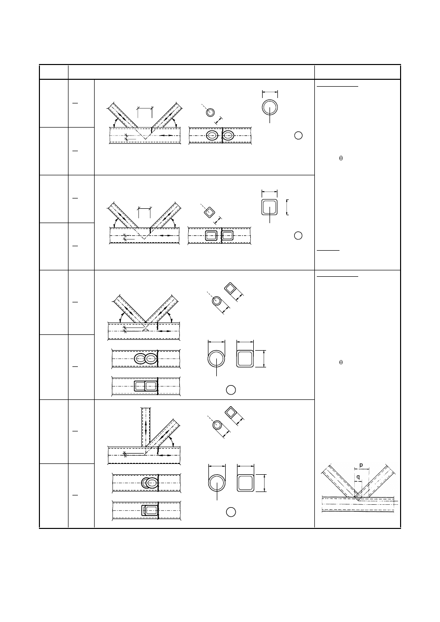
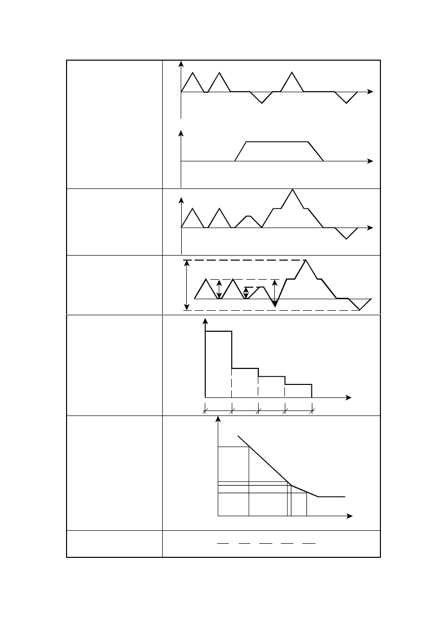
$QQH[ $ >QRUPDWLYH@ ± 'HWHUPLQDWLRQ RI IDWLJXH ORDG SDUDPHWHUV DQG
YHULILFDWLRQIRUPDWV
$
'HWHUPLQDWLRQRIORDGLQJHYHQWV
(1)
Typical loading sequences that represent a credible estimated upper bound of all service load events
expected during the fatigue design life should be determined using prior knowledge from similar structures,
see Figure A.1 a).
$
6WUHVVKLVWRU\DWGHWDLO
(1)
A stress history should be determined from the loading events at the structural detail under
consideration taking account of the type and shape of the relevant influence lines to be considered and the
effects of dynamic magnification of the structural response, see Figure A.1 b).
(2)
Stress histories may also be determined from measurements on similar structures or from dynamic
calculations of the structural response.
$
&\FOHFRXQWLQJ
(1)
Stress histories may be evaluated by either of the following cycle counting methods:
–
rainflow method
–
reservoir method, see Figure A.1 c).
to determine
–
stress ranges and their numbers of cycles
–
mean stresses, where the mean stress influence needs to be taken into account.
$
6WUHVVUDQJHVSHFWUXP
(1)
The stress range spectrum should be determined by presenting the stress ranges and the associated
number of cycles in descending order, see Figure A.1 d).
(2)
Stress range spectra may be modified by neglecting peak values of stress ranges representing less than
1% of the total damage and small stress ranges below the cut off limit.
(3)
Stress range spectra may be standardised according to their shape, e.g. with the coordinates
0
,
1
=
σ
∆
and
0
,
1
n
=
Σ
.
$
&\FOHVWRIDLOXUH
(1)
:KHQ XVLQJ WKH GHVLJQ VSHFWUXP WKH DSSOLHG VWUHVV UDQJHV
i
VKRXOG EH PXOWLSOLHG E\
Ff
and the
IDWLJXHVWUHQJWKYDOXHV
C
GLYLGHGE\
Mf
in order to obtain the endurance value N
Ri
for each band in the
spectrum. The damage D
d
during the design life should be calculated from:
∑
=
n
i
Ri
Ei
d
N
n
D
(A.1)
where n
Ei
is the number of cycles associated with the stress range
i
Ff
σ
∆
γ
for band i in the factored
spectrum
3DJH
Final draft
SU(1
17 April 2003
N
Ri
is the endurance (in cycles) obtained from the factored
R
Mf
C
N
−
γ
σ
∆
curve for a stress range of
Ff
i
(2)
On the basis of equivalence of D
d
the design stress range spectrum may be transformed into any
equivalent design stress range spectrum, e.g. a constant amplitude design stress range spectrum yielding the
fatigue equivalent load Q
e
associated with the cycle number n
max
=
Q
i
or Q
E,2
associated with the cycle
number N
C
= 2
×10
6
.
$
9HULILFDWLRQIRUPDWV
(1)
The fatigue assessment based on damage accumulation shall meet the following criteria:
–
based on damage accumulation:
D
d
≤ 1,0
(A.2)
–
based on stress range:
Mf
C
m
d
2
,
E
Ff
D
γ
σ
∆
≤
σ
∆
γ
where m = 3
(A.3)
Final draft
3DJH
17 April 2003
SU(1
a) Loading sequence:
Typical load cycle
(repeated n-times in the
design life)
T
P
1
T
P
2
b) Stress history at detail
T
F
c) Cycle counting (e.g.
reservoir method)
)F
3
)F
1
)F
2
)F
4
d) Stress range spectrum
)F
1
)F
)F
3
)F
2
n
1
n
4
n
3
n
2
)F
4
N
e) Cycles to failure
log N
log
)F
N
2
N
1
N
4
N
3
)F
1
)F
4
)F
3
)F
2
f) Damage summation
(Palmgren-Miner rule)
∑
≤
+
+
+
=
L
4
4
3
3
2
2
1
1
i
i
D
N
n
N
n
N
n
N
n
N
n
)LJXUH$&XPXODWLYHGDPDJHPHWKRG
3DJH
Final draft
SU(1
17 April 2003
$QQH[%>QRUPDWLYH@±)DWLJXHUHVLVWDQFHXVLQJWKHJHRPHWULFKRWVSRW
VWUHVVPHWKRG
(1)
For the application of the geometric stress method detail categories are given in Table B.1 for cracks
initiating from
–
toes of butt welds,
–
toes of fillet welded attachments,
–
toes of fillet welds in cruciform joints.
7DEOH%'HWDLOFDWHJRULHVIRUXVHZLWKJHRPHWULFKRWVSRWVWUHVVPHWKRG
Detail
category
Constructional detail
Description
Requirements
112
1
1) Full penetration butt joint.
1)
-
All welds ground flush to plate
surface parallel to direction of
the arrow.
-
Weld run-on and run-off pieces
to be used and subsequently
removed, plate edges to be
ground flush in direction of
stress.
-
Welded from both sides,
checked by NDT.
-
For misalignment see NOTE 1.
100
2
2) Full penetration butt joint.
2)
-
Weld not ground flush
-
Weld run-on and run-off pieces
to be used and subsequently
removed, plate edges to be
ground flush in direction of
stress.
-
Welded from both sides.
-
For misalignment see NOTE 1.
100
3
3) Cruciform joint with full
penetration K-butt welds.
3)
-
Weld toe angle
-
For misalignment see NOTE 1.
100
4
4) Non load-carrying fillet
welds.
4)
-
Weld toe angle
-
See also NOTE 2.
100
5
5) Bracket ends, ends of
longitudinal stiffeners.
5)
-
Weld toe angle
-
See also NOTE 2.
100
6
6) Cover plate ends and similar
joints.
6)
-
Weld toe angle
-
See also NOTE 2.
90
7
7) Cruciform joints with load-
carrying fillet welds.
7)
-
Weld toe angle
-
For misalignment see NOTE 1.
-
See also NOTE 2.
127( Table B.1 does not cover effects of misalignment. They have to be considered explicitly in
determination of stress.
127( Table B.1 does not cover fatigue initiation from the root followed by propagation through
the throat.
Wyszukiwarka
Podobne podstrony:
Eurocode 3 Part 1,9 PrEN 1993 1 9 2003
Eurocode 3 Part 1,8 prEN 1993 1 8 2003
Eurocode 3 Part 1,8 prEN 1993 1 8 2003
Eurocode 1 Part 1,3 prEN 1991 1 3 2003
Eurocode 3 Part 2 (prEN 1993 2 March 2004)
Eurocode 8 Part 4 prEN 1998 4 2003 (12 2003)
Eurocode 1 Part 1,5 prEN 1991 1 5 2003
Eurocode 3 Part 1,5 prEN 1993 1 5 2004 (Juin 2004)
Eurocode 3 Part 3 prEN 1993 3 2001
Eurocode 1 Part 1,7 prEN 1991 1 7 2003
Eurocode 3 Part 5 prEN 1993 5 (2004 Jul)
Eurocode 3 Part 5 prEN 1993 5 (2004 Jul)
Eurocode 3 Part 3 prEN 1993 3 2001
Eurocode 8 Part 1 prEN 1998 1 (12 2003)
Eurocode 8 Part 5 prEn 1998 5 (12 2003)
Eurocode 8 Part 3 prEN 1998 3 (07 2003)
więcej podobnych podstron