
An ATX or AT, 12 - 24 volt PC Power supply
DISCLAIMER : -
The drawings, procedures and words are for information only. No claims are expressed or implied as
to the safety, usefulness, or accuracy of this information. I will not accept any liability for any damages caused to
people or property from the using of this information or from any associated links. Your actions are your responsibility -
VERIFY and CHECK information out before proceeding, and don't attempt anything without the required skills, if you
cannot agree to this, leave this page now . . . . . . . Chris.
Low power PCs with huge computing powers has opened up enormous applications opportunities. No longer is it just a word processor or
number cruncher. High speed USB ports, high resolution monitors and large capacity hard disks has opened up uses in realistic games,
video and data processing and storage, and all at affordable prices. I decided to build this project as part of an eventual wireless network
system which would allow video processing and storage as well as provide some telementry for some remote systems. In searching the
net for information I discovered many MP3 car power supply systems which would have been adequate, but I finally decided to make a
"generic" power supply that would slot into any PC system, and it had to be relatively low in cost to build. I first built a power supply from
scratch using the box and some recycled parts, but later decided it was easier to modify an existing one by ripping out the old "mains"
front end and adding a new low voltage front end. In testing a couple of PCs for power requirements I discovered that they needed much
less than I originally thought. With the banishment of the old brick hard drives that required 10 amps each has left plenty of reserve in the
existing power supplies which have essentially stayed at the same old watt ratings. I tested two units with a DC "clip on" tester, so there
may be some error in the results. (at least 3%).
PC AT 100 Mhz pentium, with a 3.2G fast IDE hard drive, CD, 1.2meg and 1.4meg floppies.
+5 volt 4.88 A boot up to 2.76 A running.
+12 volt 0.35 boot up to 0.22 A running.
-5 and -12 volt lines were only a couple of milli amps.
PC ATX 700Mhz Celeron, with 2 fast hard IDE drives, 2 CDs and a 1.4 meg floppy.
motherboard drain - .
Strona 1 z 15
ATX Power supply
2008-10-01
file://G:\_A NOWE ELEKTRO\ZASILACZE KOMPUTEROWE\ATX Power supply.htm
Generated by Foxit PDF Creator © Foxit Software
http://www.foxitsoftware.com For evaluation only.

+5 volt 2.5A boot up to 0.4 A running.
+3 volt 1.9 A boot up to 1.1 A running.
+12 volt 0.25 A to 0.23 A running.
+5 volt SB line around 0.25 A from off to running.
Overall drain.
-5 volt, -12 volt were neglible again.
+5v, 4.45A bootup to 2.15A running.
+12v, 1.8A boot up to 0.63A running.
(The photo below shows the "from scratch" ATX power supply.)
Strona 2 z 15
ATX Power supply
2008-10-01
file://G:\_A NOWE ELEKTRO\ZASILACZE KOMPUTEROWE\ATX Power supply.htm
Generated by Foxit PDF Creator © Foxit Software
http://www.foxitsoftware.com For evaluation only.
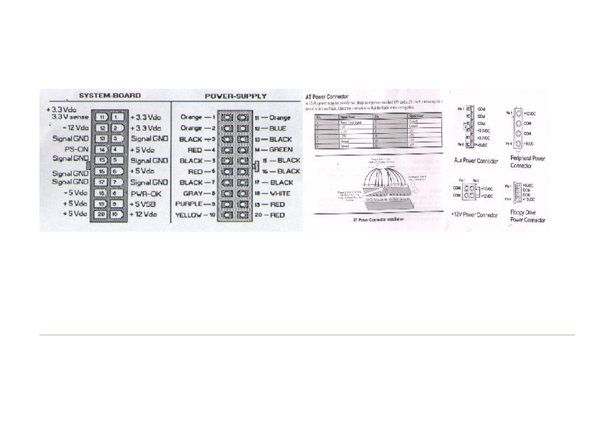
Normal mains 250 watt ATX power specifications.
3.30v @ 14A.
5.0v @ 22A.
12.0v @ 8A.
Strona 3 z 15
ATX Power supply
2008-10-01
file://G:\_A NOWE ELEKTRO\ZASILACZE KOMPUTEROWE\ATX Power supply.htm
Generated by Foxit PDF Creator © Foxit Software
http://www.foxitsoftware.com For evaluation only.

5.0 v SB @ 0.8A.
-5.0v @ 0.3A.
-12.0v @ 0.8A
The "from scratch" PS unit:
I used a standard PC power supply box, and recovered many usable parts from an old fried one. The toroids, low voltage high capacity
capacitors, fast power diodes, leads and connectors are all reusable. The power supply consists of three separate switchers to provide
power for the +3 and +5 and +12 volt lines; the other low current supplies, -5 and -12 volt lines are auxiliary windings from the main ones.
The switching regulators are identical except for the adjust bias resistor (and trimming resistor), and only one is shown on the schematic.
A linear regulator is also used to supply the +5 VSB line. This is used to drive the "stand-by" circuits in the computer to automatically and
manually turn it on. (this supply line is present all the time, until unplugged from the mains, or in this case, disconnected from the battery
supply). The rest of the circuitry provides under and over voltage protection and power disconnect circuits.
The heart of the switchers are the LM317 regulators. These are a 1.5 A rugged linear regulator that are used to drive (switch) a MJ2955
transistor ( This is a PNP transistor with a 115 watt rating, max collector current of 15 Amps. As current is drawn through the regulator a
voltage is impressed across the 20 ohm input resistor which supplies bias to the switching transistor. The transistor passes battery current
through to the toroid and loads. Once the correct output voltage is attained the regulator shuts down and also shuts off the transistor. The
output is sensed via the "Adjust" terminal of the regulator. The energy stored in the toroid after the transistor has switched off is released
to the load via a fast power diode. A transistor is used to clamp the "adjust" voltage to ground in "shutdown" conditions as well , this will
fold back the output to about 1.2 volts. All power consumption is distributed as evenly as possible across the three switch supplies.
Strona 4 z 15
ATX Power supply
2008-10-01
file://G:\_A NOWE ELEKTRO\ZASILACZE KOMPUTEROWE\ATX Power supply.htm
Generated by Foxit PDF Creator © Foxit Software
http://www.foxitsoftware.com For evaluation only.
The PS-ON signal from the PC is a TTL logic compatible signal which turns on the power supply when made an active low. (open circuit
or high is off). When this is asserted a CMOS oscillator is released which drives a small toroid to provide the gate voltage to power on the
DC power FET and allow power to the switchers. This FET has a very low turn on resistance and as such doesn't waste much power. (I
used a voltage doubler at first to supply the gate but found I needed a good strong gate voltage to allow the FET to give me it's best Rds,
so I then used the toroid - In further research I have found a P channel FET with a 100v Vds and a 50A Id (Rds 55 mOhms) which would
negate the need for the oscillator etc, P-channels with good current ability have not been available until recently. This mob also have a
340A N channel FET with a Rds of 3 mOhm!, makes the rest look pretty ordinary - www.ixys.com). A B.P. capacitor is coupled from the
Strona 5 z 15
ATX Power supply
2008-10-01
file://G:\_A NOWE ELEKTRO\ZASILACZE KOMPUTEROWE\ATX Power supply.htm
Generated by Foxit PDF Creator © Foxit Software
http://www.foxitsoftware.com For evaluation only.
turn on circuit to the undervoltage circuit to inhibit the undervoltage shutdown circuit until the power supply has actually turned fully on.
The "power good" signal to the motherboard is asserted when the +5, +12 and +5 VSB supply rails are ok as well as no overvoltage
condition from the comparators are found. A power good led is located near the back of the supply which is easily seen through the vents
or fan too.
Lastly the 3volt "sense" wire has not come in for special attention and is just a "supply" wire, if you wish you could run this to the regulator
sense (at the junction of 0.22 ohm and 270 ohm, disconnect the 270 ohm from the output and run it to the sense line). For the relatively
low current levels for my application I could not see much point in using this "sense" wire. Another criteria of ATX power specification is
that the 12 and 5 volt lines must be greater or equal to the 3 volt line during start up - this unit hasn't been tested so look out micro . . . .
Further, if the switchmode supply lets go and becomes a molten blob, so will your motherboard, CD, floppies and hard disks.
Know and understand the risks - you have been warned, A battery bank has enormous excitement potential !. Because of the mucking
around this "from scratch" power supply represents I decided to try to re-hash an existing PC AT or ATX supply and give this one the big
flick. . . . (and a transistor junction 1 thou thick is all there is between life and death of the PC).
A better way . . . . . A Re-Hashed Power supply - ATX or AT.
Strona 6 z 15
ATX Power supply
2008-10-01
file://G:\_A NOWE ELEKTRO\ZASILACZE KOMPUTEROWE\ATX Power supply.htm
Generated by Foxit PDF Creator © Foxit Software
http://www.foxitsoftware.com For evaluation only.
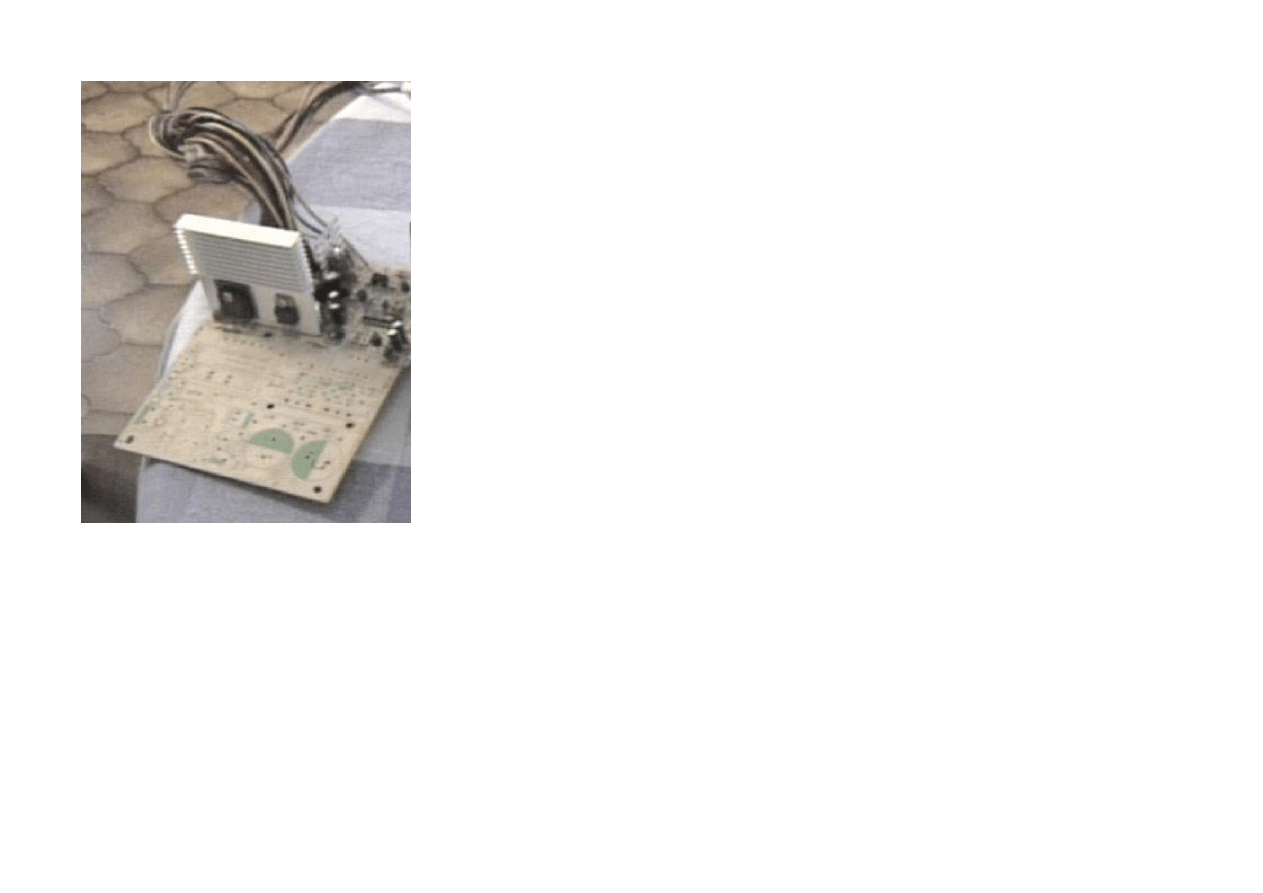
"One I prepared earlier" . . . . . . (only the output circuitry left on the board, all the mains section stripped out)
Strona 7 z 15
ATX Power supply
2008-10-01
file://G:\_A NOWE ELEKTRO\ZASILACZE KOMPUTEROWE\ATX Power supply.htm
Generated by Foxit PDF Creator © Foxit Software
http://www.foxitsoftware.com For evaluation only.
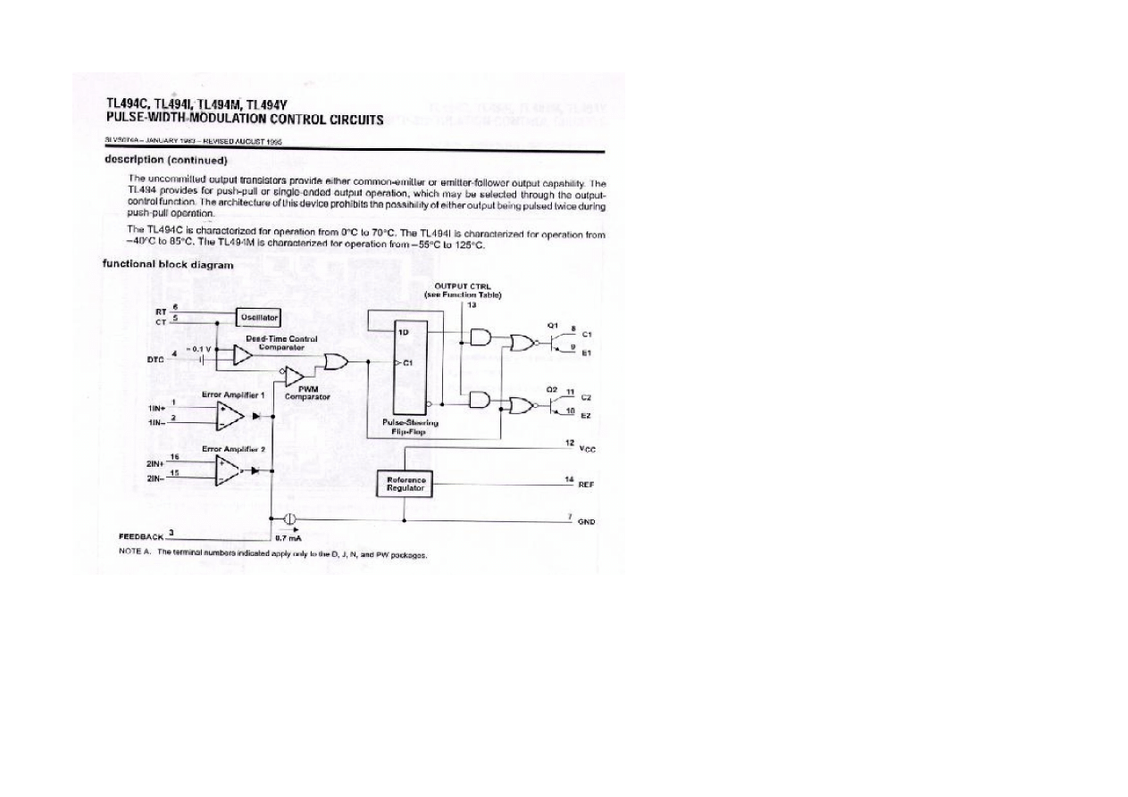
While looking at a few PC power supplies I realised there was a great heap of space utilised in the rectification, filtering and switching of
the mains supply. Most of the PC power supplies are designed similarly (power good circuits may vary) with a 320-340v dc input
(Australia), feeding a couple of transistors driving a ferrite transformer to provide the required supply rails. The regulator is usually a
TL494 (or a 494 in disguise, or perhaps a UC3844, TL594, MC34xx), they usually have a couple of additional small ferrite transformers,
one to supply the transistor drives and the another for a supply voltage to the regulator. Some may even regulate by opto feedback. This
general arrangement is ideal for modification because there is plenty of room for the new switching FETS and heatsink, and most of the
regulator and supply lines, filtering etc has already been designed, built and was working. All that is necessary is to wind a new toroid to
Strona 8 z 15
ATX Power supply
2008-10-01
file://G:\_A NOWE ELEKTRO\ZASILACZE KOMPUTEROWE\ATX Power supply.htm
Generated by Foxit PDF Creator © Foxit Software
http://www.foxitsoftware.com For evaluation only.
accommodate the new input supply voltage and existing supply rails, intergrate drive circuitry to the FETS and a supply to the regulator
chip . . . .
(The mind boggles thinking of the applications these old recycled power supplies could be used for with a bit of tinkering).
I pulled the
ferrite transformer
apart and found the 5volt winding with 3 turns a side of a centre tap, and 2 more windings each side with 4
turns each for the +12volt supply. The -12 and -5 volt supplies are coupled to another toroid in the output circuit and track with the 5 volt
rail. But who cares, I know this all worked (once). The primary had 20 turns of 25 thou on the bottom layer seriesed with a further 20 on
the top layer to provide good coupling, (The secondaries are sandwiched by the primary). The secondary windings were trifular 32 thou
Strona 9 z 15
ATX Power supply
2008-10-01
file://G:\_A NOWE ELEKTRO\ZASILACZE KOMPUTEROWE\ATX Power supply.htm
Generated by Foxit PDF Creator © Foxit Software
http://www.foxitsoftware.com For evaluation only.

(5v) and bifular 32 thou (12v) copper enameled wire as these are the high current windings. (Bi-fular / Tri-fular windings ? ? - Bi is 2 Tri is
3 and so on, It is better to use many small diameter insulated wires than one thick wire because electron flow is concentrated at the
surface of each wire, particularly when the frequency is increased - "skin effect" - see "
12 - 24v fluro lighting
" page for a picture on how to
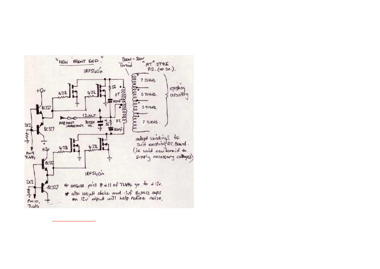
wind "bifular"). The FET drives goes to the TL494 outputs. ( pins 8 and 11 - usually these go to a pair of driver transistors to drive the base
isolating transformer, this stuff can be ripped out. I had to isolate pins 9 and 10 as they were joined, run these lines to the gates and
isolate and take pins 8 and 11 to Vcc however). The supply line for the regulator needs 12 volts and goes to pin 12. (tracing the circuit out
fully is a good idea as it will help you understand what is going on and how to "link" things in). Usually the "power good" circuitry will be
located and intergrated all within the output stage and will require no attention. The new transformer needs to be wound large enough to
cope with your required power demands and also not go into magnetic saturation with use. A good guide is to select something simular to
the original, or use the original if you can get it apart without damage, and use the same turns per volt. I used a big toroid (50x16mm), but
nearly any chunk of ordinary ferrite (for power - material 72, 75, 77, F, J etc), will work with enough mucking around. (best efficiencies for
ferrite is type is between 50Khz to 1 Mhz, and if the frequency is kept to the low end ordinary enamelled copper winding wire is fine). I
stayed close to the original design in turns per volt and decided on 1 turn per volt (that way I didn't need a calculator). The 5 volt winding
(5 turns) was wound trifulr with 32 thou, 12 volt extention winding (7 turns) to the 5 volt was bifular with 32 thou. The primary was 10 wires
of 25 thou (tenfular?), centre tapped and 8 turns a side. (a lower ratio so it doesn't run flat out to get the rail voltages, and gives it some
reserve.) The windings are distributed around the entire toroid to provide good coupling. To confess the power supply didn't work the first
time I turned it on because I had been to exuberant in pulling out unnecessary components. Once I realised I pulled out an electrolytic
used in the error amp circuit it worked beautifully. All rails were perfect, everything ran cool.
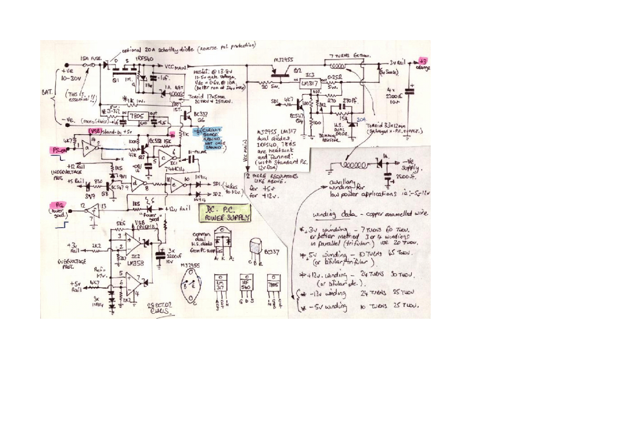
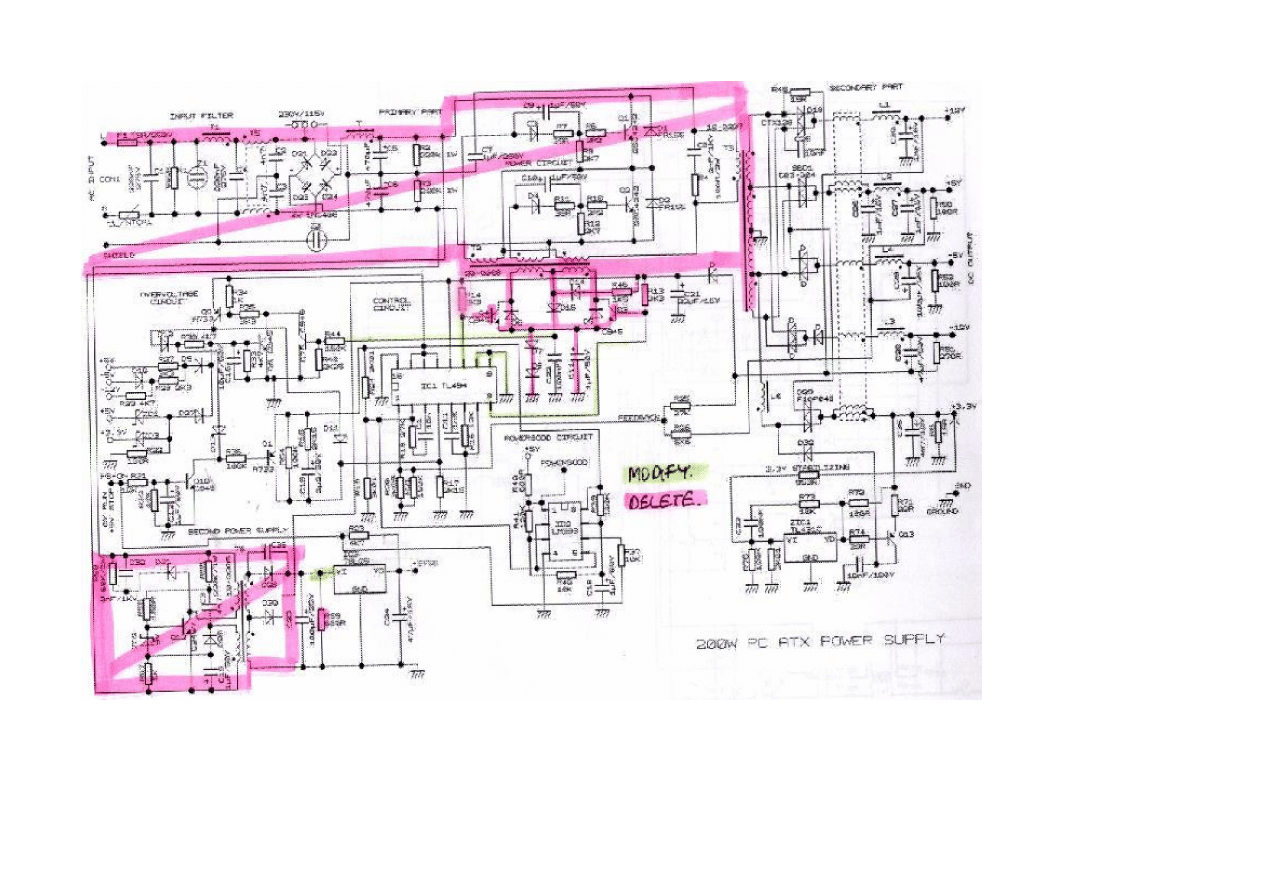
(Below is a "typical" circuit of a 200 watt ATX power supply schematic to show you roughly what to do and how they are layed out, (it is
virtually impossible to get hold of the correct schematic).
red=remove, green=play with!)
Strona 10 z 15
ATX Power supply
2008-10-01
file://G:\_A NOWE ELEKTRO\ZASILACZE KOMPUTEROWE\ATX Power supply.htm
Generated by Foxit PDF Creator © Foxit Software
http://www.foxitsoftware.com For evaluation only.
Depending on what sort of PC power supply you started out with will largely determine how much extra effort is needed to get you where
you want to go. (For example, if you want to make a 12 volt ATX supply, start with one and not an AT type, because you will need to
design and add an extra 3 volt winding, rectifier, filters and stabilizator circuitry, then PC_ON circuitry etc. - not impossible but theres
probably both types sitting in someones bin). The ATX style power supply must supply a 5 volt standby supply. This is usually a second
Strona 11 z 15
ATX Power supply
2008-10-01
file://G:\_A NOWE ELEKTRO\ZASILACZE KOMPUTEROWE\ATX Power supply.htm
Generated by Foxit PDF Creator © Foxit Software
http://www.foxitsoftware.com For evaluation only.

little switching regulator which also runs off the mains which for our exercise can be easily modified by running the linear regulator straight
from your DC input line. (By the way most of the linear regulators can't handle more than 35v input to output differential, so a 24v lead
acid battery bank is getting close to it's limits - but the nice thing is battery supply is much cleaner than the electric utilities mains!. I would
also recomend using a 1 A fuse on this regulators input, and placing a 5v6 5 watt zenner across the output, or better yet an SCR crowbar
circuit.)
Strona 12 z 15
ATX Power supply
2008-10-01
file://G:\_A NOWE ELEKTRO\ZASILACZE KOMPUTEROWE\ATX Power supply.htm
Generated by Foxit PDF Creator © Foxit Software
http://www.foxitsoftware.com For evaluation only.
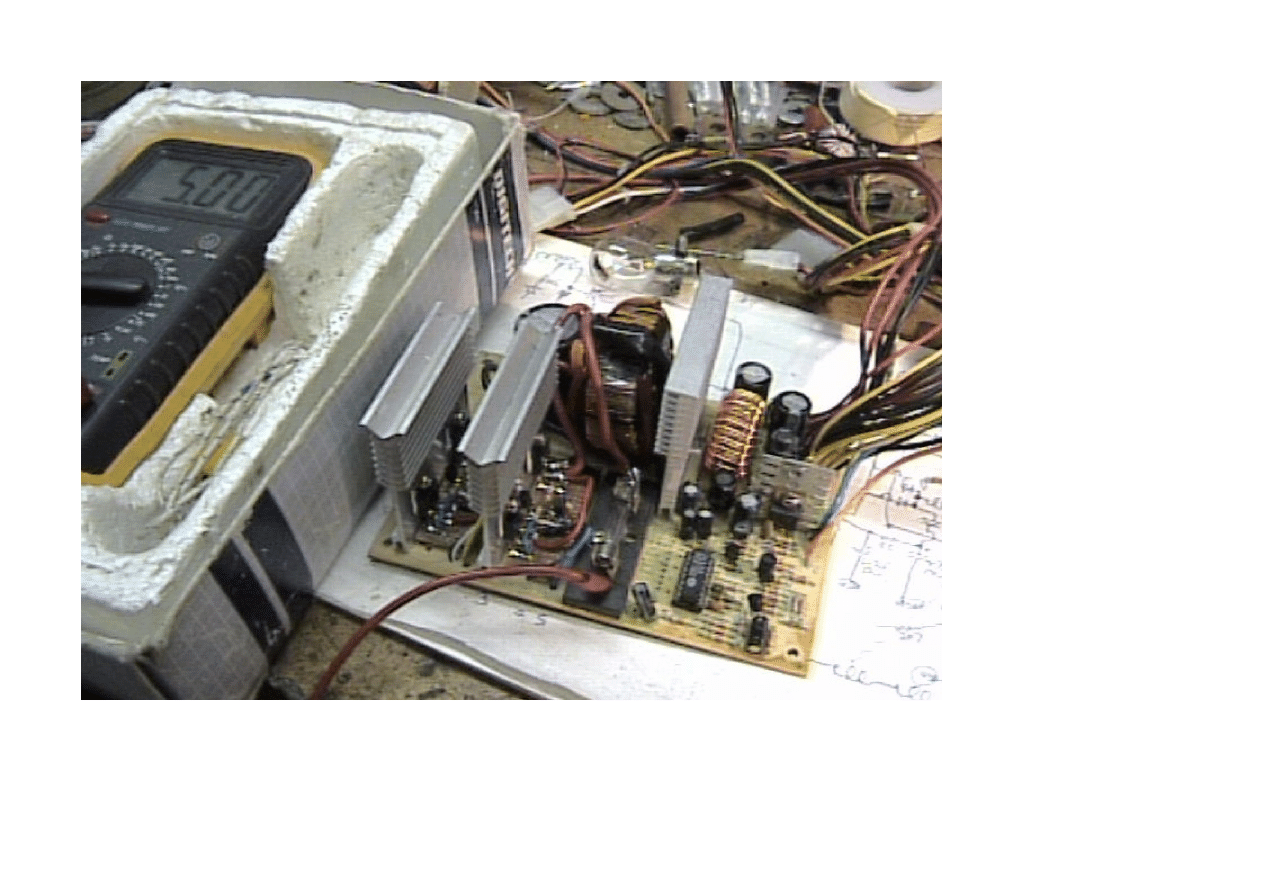
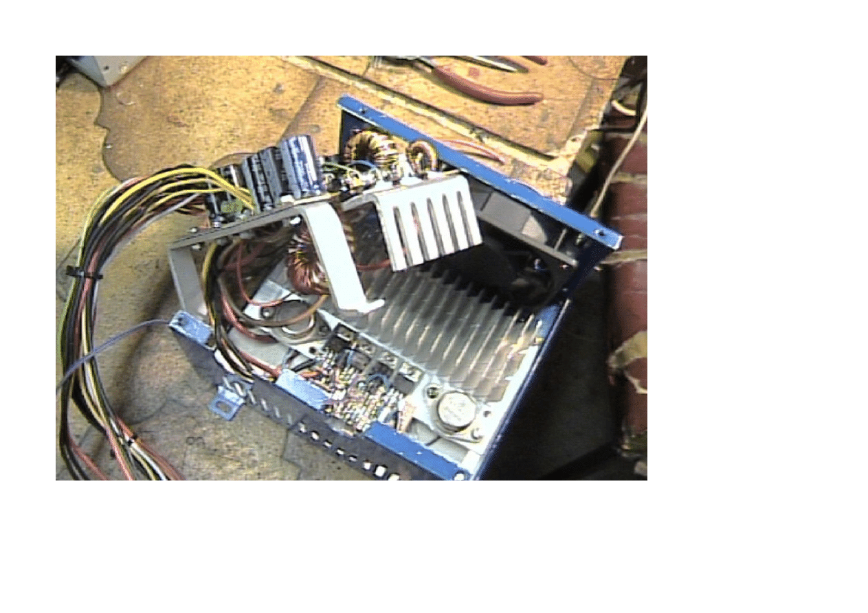
The above picture shows the re-hashed PS, 4 IRF540 are mounted on the two heatsinks on the left, the FET leads, gate resistors, driver
transistors and high current fly wires are mounted on a strip of vero board. A 10000uf cap is behind the FETS and the toroid is beside that
standing up. There is not much to explain because the modification is so easy. This took about 10 times less time to knock up than the
"from scratch" version, and being a transformed supply it is a much much safer solution for your PC. (The cap standing next to the fuse
Strona 13 z 15
ATX Power supply
2008-10-01
file://G:\_A NOWE ELEKTRO\ZASILACZE KOMPUTEROWE\ATX Power supply.htm
Generated by Foxit PDF Creator © Foxit Software
http://www.foxitsoftware.com For evaluation only.

was the one I ripped out and it needed to be there!). The average PC (without monitor/printer etc.) should run on about 1.5 to 2.5 A @
13.8v after boot up and this could be reduced further by using some of the BIOS power saving functions. Running the PS at these low
power levels will yeild about 64% efficency, but this improves as the power level is increased.
If you require a 24 volt power supply then design the main toroid input winding with double the turns suggested for the 12 volt model.
Ensure the FETS Vds can tolerate at least double your input supply voltage, and you will be able to do the job with half the FETS as the
current will be about half. (In fact if you could be certain to always draw low power you could use 2 fets @ 12v. Also use a 12 - 15 v linear
regulator to provide the Vcc to the regulator etc when running a higher input voltage.
MP3 - It should be possible to wind a couple of "new" auxillary windings to supply + and - 40 volts for an audio amplifier for a combined
mp3 system, (though you may need to beef the input circuit up a bit as that could draw as much as 60 amps from the battery, say 6
IRF40s and more input winding wires, say 16, also the amp windings should be last on with a layer of insulation under it, for isolation).
(One last thing . . . . . please use an input fuse, . . . . This project uses only low voltages and easily available recycled parts so should be
ideal for individuals, clubs, or school groups to safely learn more about switchmode supplies and the "insides" of a PC - have fun, Chris)
(I converted another ATX one . . . . stay tuned, many thanks Christian for letting me know about my bad link, hope they work now -
31/12/02)
Some Links:
Power Designers
- Has many good articles on their site on PWM, Converters, Inverters, FETS, diodes etc. . .
Power Stream
- Has more good articles with a slant on battery charging. Good info on batteries too.
SMPS Design
- A tutorial on switching-mode power supply design by Jerrold Foutz
Goggle list of power supplies
- You should find something here.
Strona 14 z 15
ATX Power supply
2008-10-01
file://G:\_A NOWE ELEKTRO\ZASILACZE KOMPUTEROWE\ATX Power supply.htm
Generated by Foxit PDF Creator © Foxit Software
http://www.foxitsoftware.com For evaluation only.

Back to projects page
Strona 15 z 15
ATX Power supply
2008-10-01
file://G:\_A NOWE ELEKTRO\ZASILACZE KOMPUTEROWE\ATX Power supply.htm
Generated by Foxit PDF Creator © Foxit Software
http://www.foxitsoftware.com For evaluation only.
Wyszukiwarka
Podobne podstrony:
Convert Computer ATX Power Supply to Lab Power Supply
NE054 ZASILACZ REGULOWANY 12V 24V
ATX power switch substitute
Convert Computer ATX Power Supply to Lab Power Supply
ATX power supply schematic[1]
Ersatz fuer ATX Power Switch
ATX Power Supply Tester ELEKTOR
ATX power supply connector pinout
atx Power Supply Design Guide
NE040 KONWERTER PRZETWORNICA 18V 24V ACDC na 12V DC
(Wydruk – ATX Switching Power Supply 13,8 V Proste zmiany w celu zwiększenia napięcia wyjściowego Ja
How to Modify an ATX Computer Power Supply
Schemat złacza ATX 12V 24 PIN
prezentacja power media
Power D, zebranie zarządu
karty płatnicze (power point)
więcej podobnych podstron