SLC 500™ RTD/Resistance
Input Modules
(Catalog Numbers 1746-NR4 and 1746-NR8)
Technical Data
1746-NR4
1746-NR8
The RTD/Resistance Input Modules enhance the present
temperature control capabilities of your SLC 500™ system by
providing the capability to interface with 12 different types of
RTDs and four different direct resistance ranges. RTDs are
known for their accuracy, repeatability, linearity and long-term
stability. The modules’ RTD sensor combination is easy to install and
provides greater output (ohms/°C or ohms/°F), accuracy, linearity and
repeatability with temperature, as compared to other methods of
temperature measurement/control. Each channel accepts different
types of RTD inputs (for example, platinum, nickel, copper, and
nickel-iron) and accepts resistance devices like potentiometers. The
modules convert RTD input to temperature (°C,°F) and convert
resistance device input to ohms.
Two modules are available, giving you the choice between the
4-channel 1746-NR4 and the 8-channel 1746-NR8 module.
Inside . . . . . . . . . . . . . . . . . . . page
Hardware Overview. . . . . . . . . . . . . 2
Module Operation . . . . . . . . . . . . . . 3
RTD/Resistance Compatibility and
Specifications . . . . . . . . . . . . . . . . . 6
Module Wiring . . . . . . . . . . . . . . . 11
Module Addressing . . . . . . . . . . . . 11
Module Diagnostics . . . . . . . . . . . 20
Specifications . . . . . . . . . . . . . . . . 21
Terms and Abbreviations. . . . . . . . 27

Publication 1746-TD007B-EN-P - August 2000
2
SLC 500™ RTD/Resistance Input Modules
Both modules provide channel configuration flexibility that
allows you to define the operational characteristics for each
input channel via your ladder logic programming. There are no
hardware DIP switches to set. Each channel is configured using your
ladder program and may be dynamically reconfigured without
handling the hardware. The modules perform on-board scaling to
engineering units. For example, you can specify RTD or resistance
device input, temperature resolution in degrees or tenths of a degree
Celsius or Fahrenheit, and resistance device resolution in ohms, tenths
of an ohm and one-hundredth of an ohm. In addition to engineering
units, you can format conversion of the input data to proportional
counts or scaled-for-PID.
The choice of four filter frequencies permits you to select input
noise filtering appropriate to the application and surrounding
environment. 50Hz and 60Hz noise can be filtered from the input
signal for greater noise rejection and resolution. For applications
where system response speed is critical, minimum filtering can be
selected to reduce the time it takes a step change at the input to be
made available to the SLC 500 controller.
User calibration is not required. Each channel undergoes a
calibration cycle at power-up, on channel configuration, or on your
command to compensate for module component drift. This enhances
module accuracy and saves valuable service time and money. The
1746-NR8 module can also be configured to perform an
autocalibration cycle every five minutes.
Fault diagnostics check for open circuits, short circuits or
out-of-range values; then indicate operational problems on
status LEDs. Channel status LEDs and diagnostic bits signal you if
input channel data is out of range or if an open-circuit or short-circuit
condition is present. Channel configuration validity is also checked. In
addition, a module status LED differentiates recoverable channel
errors from more serious module-related problems, saving you
troubleshooting time and money.
The modules provide high accuracy in a small package. Typical
module accuracy is 0.05% of full scale for platinum RTDs. In addition,
two current sources per channel are user-selectable to limit RTD
self-heating and provide greater system temperature accuracy.
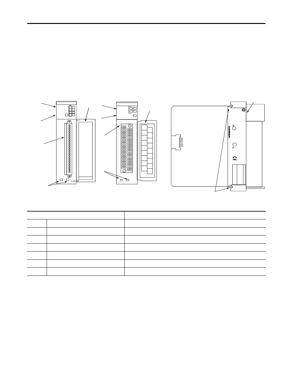
Hardware Overview
The modules fit into any single-slot of an SLC 500 modular system
(except the processor slot), or an SLC 500 fixed system expansion
chassis. The 1746-NR4 has four input channels. The 1746-NR8 has
eight input channels. Inputs are multiplexed into an A/D converter.
There are no output channels on the module.
Publication 1746-TD007B-EN-P - August 2000
SLC 500™ RTD/Resistance Input Modules
3
The modules contain a removable terminal block providing
connection for any mix of RTD sensors or resistance input devices.
The modules interface with up to 12 RTD types such as platinum,
nickel, copper, and nickel-iron, and with resistance devices such as
potentiometers.
Module configuration is done via the user program. There are no DIP
switches.
Module Operation
At module power-up, a series of internal diagnostic tests is performed.
If any diagnostic test fails, the module enters the module error state. If
all tests pass, the module initializes its hardware and software
environment and turns on the module status LED. During power-up,
the RTD module does not communicate with the processor.
SLC
500
CA
T
WIN(21)1P0EF7CO
Mfg:02
INPUT
RTD/Resistance
INPUT
MODULE
INPUT
SIGNAL
RANGES
RESIST
ANCE:
CHL 1
SHIELD
SHIELD
CHL 0
RTD
SHIELD
SER
FRN
UL
LISTED
IND.
CONT
.EQ.
FOR
HAZ.
LOC.
A196
CLASS
I,
GROUPS
A,
B,
C
AND
D,
DIV
.2
OPERA
TING
SA
RT
D
TYPES:
TEMPERA
TURE
CODE
T3C
MODULE STATUS
0
1
2
3
CHANNEL
STATUS
RTD/resistance
1746-NR4
1234567812
RTD
CHL 0
SENSE
CHL 1
SENSE
CHL 0
RETRN CHL 1
RETRN
SHIELD
CHL 3
CHL 2
RTD
RTD
CHL 2
SENSE CHL 3
SENSE
CHL 2
RETRN CHL 3
RETRN
SHIELD
1746-NR4
SHIELD
PLA
TINUM,
COPPER
NICKEL,
NICKEL±IRON
150
W
,500
W
,1000
W
,3000
W
B2
MADE
IN
U.S.A.
1
2
3
4
7
5
6
R
R
RTD / resistance
INPUT
MODULE
CHANNEL
ST ATUS
0 4
1 5
2 6
3 7
1
2
3
4
5
RTD 0
Sense 0
Return 0
RTD 1
Sense 1
Return 1
RTD 2
Sense 2
Return 2
RTD 3
Sense 3
Return 3
RTD 4
Sense 4
Return 4
RTD 5
Sense 5
Return 5
RTD 6
Sense 6
Return 6
RTD 7
Sense 7
Return 7
1746-NR8
1746-NR8
1746-NR4
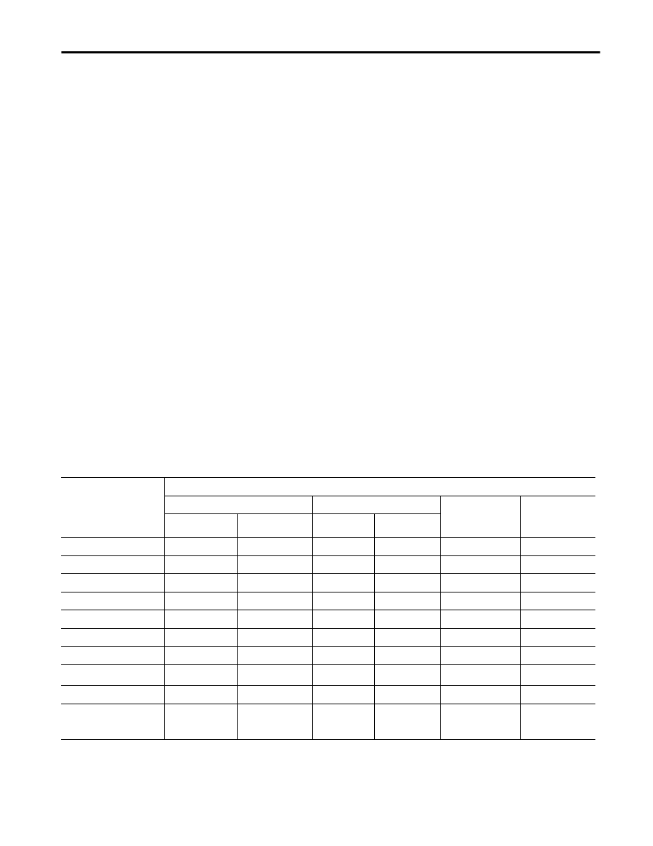
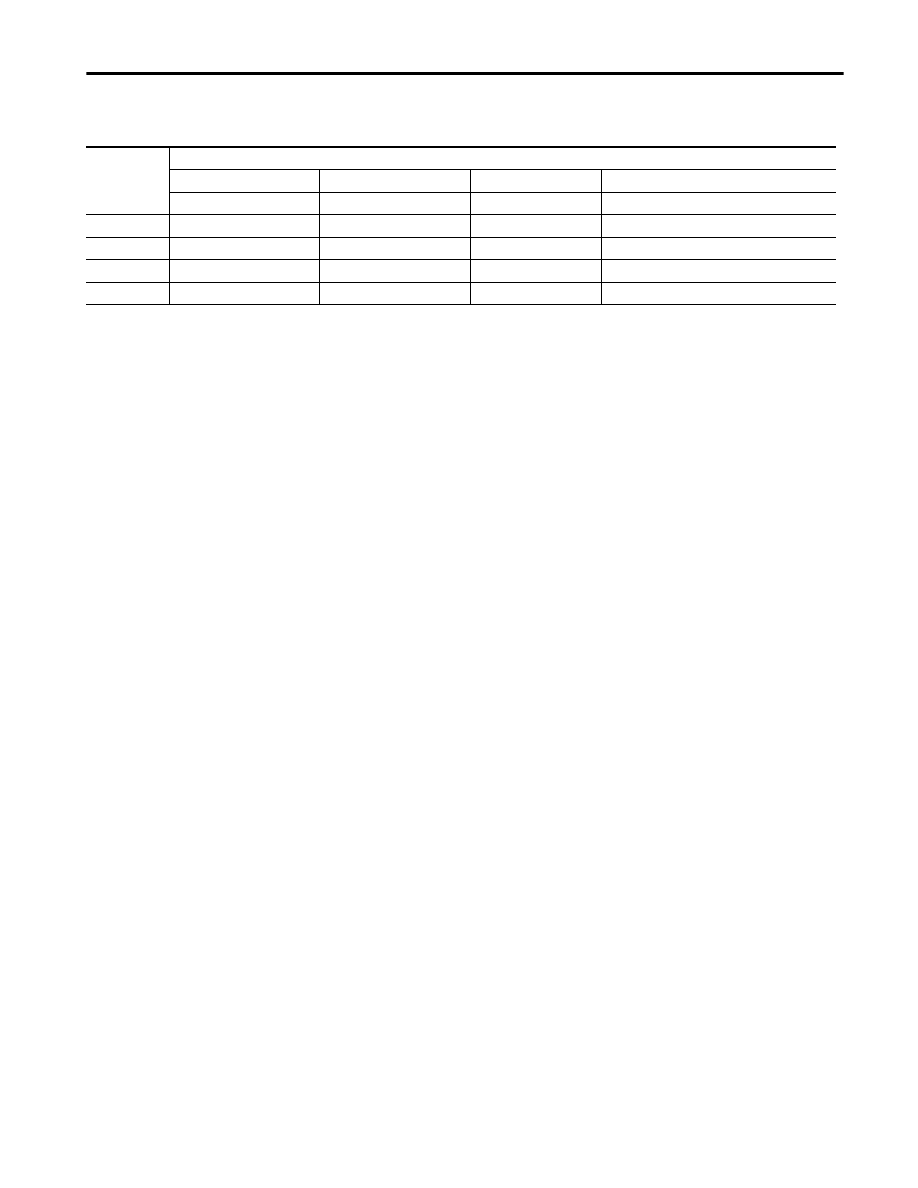
Table 1 Hardware Features
Feature
Function
1
Channel Status LED Indicators (Green)
Displays operating and fault status of each channel
2
Module Status LED (Green)
Displays module operating and fault status
3
Removable Terminal Block
Provides physical connection to input devices
4
Cable Tie Slots
Secures wiring from module
5
Door Label
Permits easy terminal identification
6
Side Label (Nameplate)
Provides module information
7
Self-Locking Tabs
Secures module in chassis slot
Publication 1746-TD007B-EN-P - August 2000
4
SLC 500™ RTD/Resistance Input Modules
After power-up checks are complete, the RTD module waits for valid
channel configuration data from your SLC ladder logic program
(channel status LEDs off). After configuration data is written to one or
more channel configuration words and the respective channel enable
bits are set by the user control program, the channel status LEDs go
on and the module continuously converts the RTD or resistance input
to a value within the range you selected for the enabled channels. The
module is now operating in its normal state.
Each time a channel is read by the module, that data value is tested
for an under-range, over-range, open-circuit or short-circuit condition.
If such a condition is detected, an error bit is set in the channel status
word and the appropriate channel LED blinks.
The SLC processor reads the converted RTD or resistance data from
the module at the end of the program scan, or when commanded by
the ladder program. The processor and RTD module determine that
the backplane data transfer was made without error, and the data is
used in your ladder program.
Calibration
The RTD modules are initially calibrated at the factory. The modules
also have an autocalibration function. Autocalibration compensates for
offset and gain drift of the analog circuitry caused by temperature
change within the module. When a channel becomes enabled, the
module configures the channel and performs the autocalibration on
the channel. Each of the module’s channels undergoes a calibration
cycle at power-up, on channel configuration, or on your command via
the ladder program.
A single-point calibration procedure can also be used to improve the
accuracy of the RTD module and cable combination to ±0.2°C. No
external, user-supplied device is required for autocalibration.
The 1746-NR8 module can also be configured to perform an
autocalibration cycle every 5 minutes.
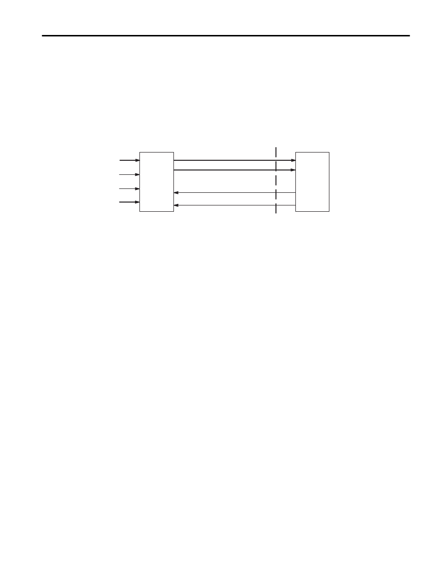
SLC 500
Processor
1746-NR4
Input
Module
Channel Data Words
Channel Status Words
Scaling Limit Words
Channel Configuration Words
RTD/Resistance
Analog Signals
Chassis Backplane
Publication 1746-TD007B-EN-P - August 2000
SLC 500™ RTD/Resistance Input Modules
5
Compatibility with Controllers and RTD Sensors
The modules are fully compatible with all SLC 500 fixed and modular
controllers. They are compatible with all RTDs that conform to the
international and local standards shown in Table 2, “RTD Standards” .
Compatibility in a Fixed Expansion Chassis
The two-slot, SLC 500 fixed I/O expansion chassis supports only
specific combinations of modules. The table below lists invalid
combinations.
Refer to the 1746-NR4 SLC 500™ RTD/Resistance Input Module User’s
Manual (publication number 1746-6.7) or 1746-NR8 SLC 500™ RTD/
Resistance Input Module User’s Manual (publication number
1746-UM003A-EN-P) for complete compatibility information.
Table 2 RTD Standards
RTD Type
α
αα
α
(3)
IEC
(4)
DIN
(5)
D100
(6)
SAMA
(7)
JIS (old)
(8)
JIS
(new)
(9)
Minco
(10)
100
Ω
Platinum
0.00385
X
X
X
200
Ω
Platinum
0.00385
X
X
X
500
Ω
Platinum
0.00385
X
X
X
1000
Ω
Platinum
0.00385
X
X
X
100
Ω
Platinum
0.03916
X
X
200
Ω
Platinum
0.03916
X
X
500
Ω
Platinum
0.03916
X
X
1000
Ω
Platinum
0.03916
X
X
10
Ω
Copper
(1)
0.00426
X
120
Ω
Nickel
(2)
0.00618
X
120
Ω
Nickel
0.00672
X
604
Ω
Nickel Iron
0.00518
X
(1) Actual value at 0°C is 9.042
Ω
per SAMA standard RC21-4-1966.
(2) Actual value at 0°C is 100
Ω
per DIN standard.
(3) a is the temperature coefficient of resistance, which is defined as the resistance change per ohm per°C.
(4) International Electrotechnical Commission Standard 751-1983.
(5) German Standard, DIN 43760-1980 and DIN 43760-1987.
(6) U.S. Standard D100
(7) Scientific Apparatus Makers Association Standard RC21-4-1966
(8) Japanese Industrial Standard JIS C1604-1981
(9) Japanese Standard JIS C1604-1989
(10) Minco Type NA (nickel) and Minco Type FA (nickel-iron)
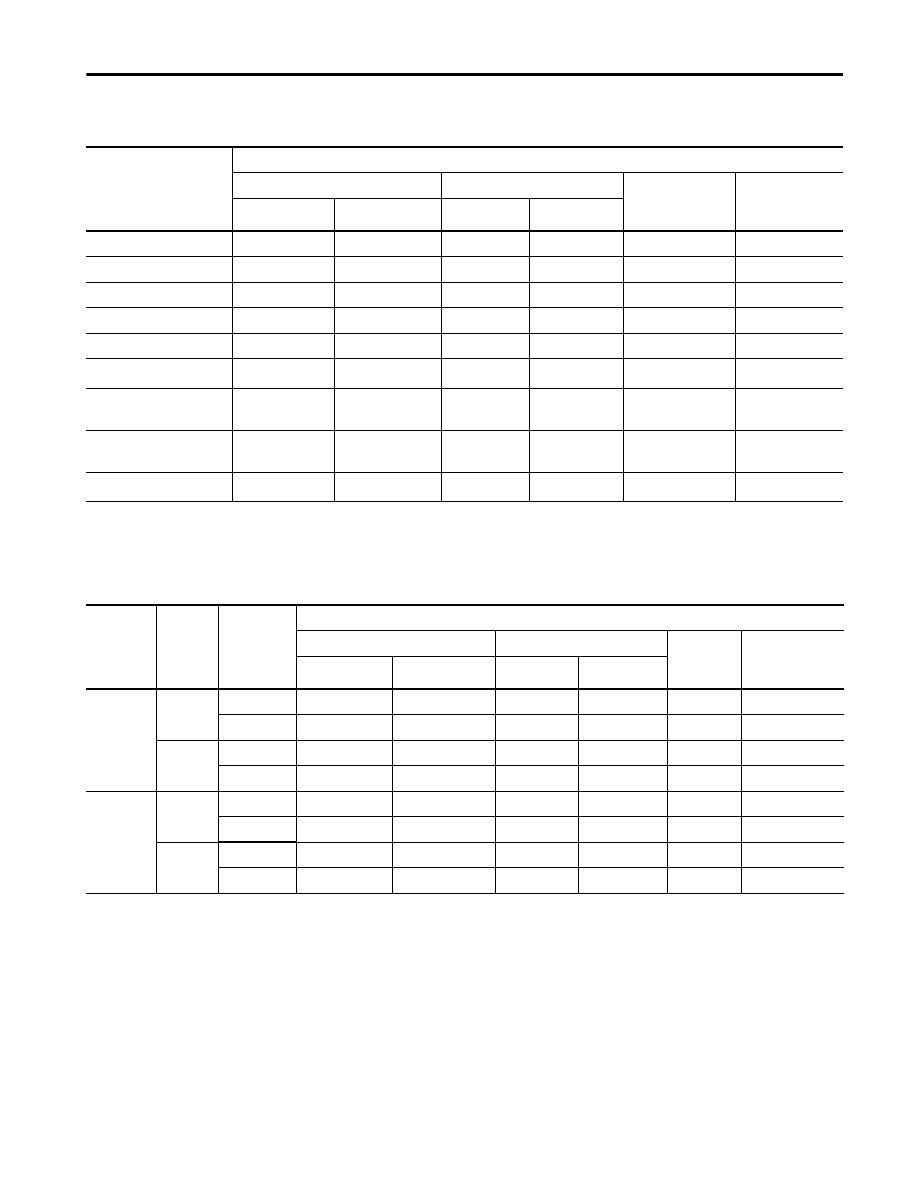
Table 3 Compatibility Requirements
The NR4 module cannot be
used with these modules:
The NR4 and NR8 modules can be used with these
modules and an external power supply:
The NR8 module cannot be
used with these modules:
OA16
NIO4I
NO4I
OA16
NI8
OAP12
FIO4I
NO4V
OAP12
NIO4I
OW16
OW16
FIO4I

Publication 1746-TD007B-EN-P - August 2000
6
SLC 500™ RTD/Resistance Input Modules
RTD/Resistance
Compatibility and
Specifications
The tables on pages 6 through 9 list the RTD types, the associated
temperature ranges, and RTD specifications for the 1746-NR4 and
1746-NR8. The tables on page 10 list the resistance ranges for
potentiometers and associated specifications.
Table 4 1746-NR4 RTD Range, Resolution, and Repeatability
RTD Input Type
(1)
Temperature Range
(0.5 mA Excitation)
(4)
Temperature Range
(2.0 mA Excitation)
Resolution
Repeatability
Platinum (385)
100
Ω
-200°C to +850°C
(-328°F to +1562°F)
-200°C to +850°C
(-328°F to +1562°F)
0.1°C
(0.2°F)
± 0.2°C
(± 0.4°F)
200
Ω
-200°C to +850°C
(-328°F to +1562°F)
-200°C to +850°C
(-328°F to +1562°F)
0.1°C
(0.2°F)
± 0.2°C
(± 0.4°F)
500
Ω
-200°C to +850°C
(-328°F to +1562°F)
-200°C to +850°C
(-328°F to +1562°F)
0.1°C
(0.2°F)
± 0.2°C
(± 0.4°F)
1000
Ω
-200°C to +850°C
(-328°F to +1562°F)
-200°C to +240°C
(-328°F to +464°F)
0.1°C
(0.2°F)
± 0.2°C
(± 0.4°F)
Platinum (3916)
100
Ω
-200°C to +630°C
(-328°F to +1166°F)
-200°C to +630°C
(-328°F to +1166°F)
0.1°C
(0.2°F)
± 0.2°C
(± 0.4°F)
200
Ω
-200°C to +630°C
(-328°F to +1166°F)
-200°C to +630°C
(-328°F to +1166°F)
0.1°C
(0.2°F)
± 0.2°C
(± 0.4°F)
500
Ω
-200°C to +630°C
(-328°F to +1166°F)
-200°C to +630°C
(-328°F to +1166°F)
0.1°C
(0.2°F)
± 0.2°C
(± 0.4°F)
1000
Ω
-200°C to +630°C
(-328°F to +1166°F)
-200°C to +230°C
(-328°F to +446°F)
0.1°C
(0.2°F)
± 0.2°C
(± 0.4°F)
Copper (426)
(2)
10
Ω
Not allowed.
(5)
-100°C to +260°C
(-148°F to +500°F)
0.1°C
(0.2°F)
± 0.2°C
(± 0.4°F)
Nickel (618)
(3)
120
Ω
-100°C to +260°C
(-148°F to +500°F)
-100°C to +260°C
(-148°F to +500°F)
0.1°C
(0.2°F)
± 0.1°C
(± 0.2°F)
Nickel (672)
120
Ω
-80°C to +260°C
(-112°F to +500°F)
-80°C to +260°C
(-112°F to +500°F)
0.1°C
(0.2°F)
± 0.1°C
(± 0.2°F)
Nickel/Iron (518)
604
Ω
-100°C to +200°C
(-148°F to +392°F)
-100°C to +200°C
(-148°F to +392°F)
0.1°C
(0.2°F)
± 0.1°C
(± 0.2°F)
(1) The digits following the RTD type represent the temperature coefficient of resistance (
α
), which is defined as the resistance change per ohm per °C. For instance,
Platinum 385 refers to a platinum RTD with
α
= 0.00385 ohms/ohm-°C, or simply 0.00385/°C.
(2) Actual value at 0°C is 9.042
Ω
per SAMA standard RC21-4-1966.
(3) Actual value at 0°C is 100
Ω
per DIN standard.
(4) The temperature range for the 1000
Ω
RTD is dependant on the excitation current.
(5) To maximize the relatively small RTD signal, only 2 mA excitation current is allowed.

Publication 1746-TD007B-EN-P - August 2000
SLC 500™ RTD/Resistance Input Modules
7
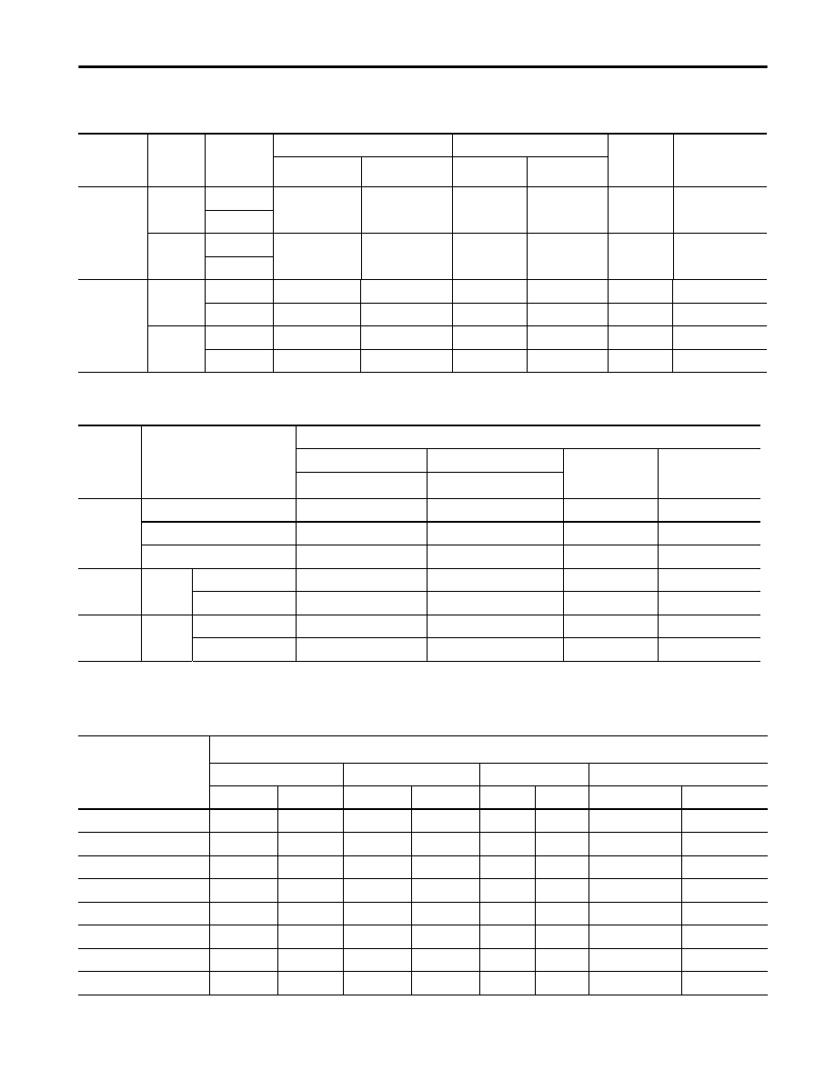
Table 5 1746-NR8 RTD Range, Resolution, and Repeatability
RTD Input Type
(1)
Temp. Range
(0.25 mA Excitation)
(4)
Temp. Range
(1.0 mA Excitation)
Resolution
Repeatability
(28 Hz, 50/60 Hz)
Platinum (385)
100
Ω
-200°C to +850°C
(-328°F to +1562°F)
-200°C to +850°C
(-328°F to +1562°F)
0.1°C
(0.1°F)
± 0.2°C
(± 0.4°F)
200
Ω
-200°C to +850°C
(-328°F to +1562°F)
-200°C to +850°C
(-328°F to +1562°F)
0.1°C
(0.1°F)
± 0.2°C
(± 0.4°F)
500
Ω
-200°C to +850°C
(-328°F to +1562°F)
-200°C to +390°C
(-328°F to +698°F)
0.1°C
(0.1°F)
± 0.2°C
(± 0.4°F)
1000
Ω
-200°C to +850°C
(-328°F to +1562°F)
-200°C to +50°C
(-328°F to +122°F)
0.1°C
(0.1°F)
± 0.2°C
(± 0.4°F)
Platinum (3916)
100
Ω
-200°C to +630°C
(-328°F to +1166°F)
-200°C to +630°C
(-328°F to +1166°F)
0.1°C
(0.1°F)
± 0.2°C
(± 0.4°F)
200
Ω
-200°C to +630°C
(-328°F to +1166°F)
-200°C to +630°C
(-328°F to +1166°F)
0.1°C
(0.1°F)
± 0.2°C
(± 0.4°F)
500
Ω
-200°C to +630°C
(-328°F to +1166°F)
-200°C to +380°C
(-328°F to +698°F)
0.1°C
(0.1°F)
± 0.2°C
(± 0.4°F)
1000
Ω
-200°C to +630°C
(-328°F to +1166°F)
-200°C to +50°C
(-328°F to +122°F)
0.1°C
(0.1°F)
± 0.2°C
(± 0.4°F)
Copper (426)
(2)
10
Ω
-100°C to +260°C
(-328°F to +500°F)
-100°C to +260°C
(-328°F to +500°F)
0.1°C
(0.1°F)
± 0.2°C
(± 0.4°F)
Nickel (618)
(3)
120
Ω
-100°C to +260°C
(-328°F to +500°F)
-100°C to +260°C
(-328°F to +500°F)
0.1°C
(0.1°F)
± 0.1°C
(± 0.2°F)
Nickel (672)
120
Ω
-80°C to +260°C
(-328°F to +500°F)
-80°C to +260°C
(-328°F to +500°F)
0.1°C
(0.1°F)
± 0.1°C
(± 0.2°F)
Nickel Iron (518)
604
Ω
-200°C to +200°C
(-328°F to +392°F)
-200°C to +180°C
(-328°F to +338°F)
0.1°C
(0.1°F)
± 0.1°C
(± 0.2°F)
(1) The digits following the RTD type represent the temperature coefficient of resistance (
α
), which is defined as the resistance change per ohm per
°
C. For instance, Platinum
385 refers to a platinum RTD with
α
= 0.00385 ohms/ohm ·
°
C or simply 0.00385 /
°
C.
(2) Actual value at 0
°
C is 9.042
Ω
per SAMA standard RC21-4-1966.
(3) Actual value at 0
°
C is 100
Ω
per DIN standard.
(4) The temperature range for the 1000
Ω, 500Ω,
and 604
Ω
RTD is dependent on the excitation current.

Publication 1746-TD007B-EN-P - August 2000
8
SLC 500™ RTD/Resistance Input Modules
Table 6 1746-NR4 RTD Accuracy and Temperature Drift Specifications
RTD Type
(1)
Accuracy
(4)
(0.5 mA Excitation)
Accuracy
(2.0 mA Excitation)
Temperature Drift
(7)
(0.5 mA Excitation)
Temperature Drift
(2.0 mA Excitation)
Platinum (385)
100
Ω
±1.0°C
(±2.0°F)
±0.5°C
(±.9°F)
±0.034°C/°C
(±0.061°F/°F)
±0.014°C/°C
(±0.025°F/°F)
200
Ω
±1.0°C
± 2.0°F)
±0.5°C
(±0.9°F)
±0.034°C/°C
(±0.061°F/°F)
± 0.014°C/°C
(± 0.025°F/°F)
500
Ω
±0.6°C
(±1.1°F)
±0.5°C
(±0.9°F)
±0.017°C/°C
(±0.031°F/°F)
±0.014°C/°C
(±0.025°F/°F)
1000
Ω
±0.6°C
(±1.1°F)
±0.5°C
(±0.9°F)
±0.017°C/°C
(±0.031°F/°F)
±0.014°C/°C
(±0.025°F/°F)
Platinum (3916)
100
Ω
±1.0°C
(5)
(±2.0°F)
±0.4°C
(±0.7°F)
±0.034°C/°C
(±0.061°F/°F)
±0.011°C/°C
(±0.020°F/°F)
200
Ω
±1.0°C
±2.0°F)
±0.4°C
(±0.7°F)
±0.034°C/°C
(±0.061°F/°F)
±0.011°C/°C
(±0.020°F/°F)
500
Ω
±0.5°C
(±0.9°F)
±0.4°C
(±0.7°F)
±0.014°C/°C
(±0.025°F/°F)
±0.011°C/°C
(±0.020°F/°F)
1000
Ω
±0.5°C
(±0.9°F)
±0.4°C
(±0.7°F)
±0.014°C/°C
(±0.025°F/°F)
±0.011°C/°C
(±0.020°F/°F)
Copper (426)
(2)
10
Ω
Not allowed
(6)
.
±0.6°C
(±1.1°F)
Not allowed.
±0.017°C/°C
(±0.031°F/°F)
Nickel (618)
(3)
120
Ω
±0.2°C
(±0.4°F)
±0.2°C
(±0.4°F)
±0.008°C/°C
(±0.014°F/°F)
±0.008°C/°C
(±0.014°F/°F)
Nickel (672)
120
Ω
±0.2°C
(±0.4°F)
±0.2°C
(±0.4°F)
±0.008°C/°C
(±0.014°F/°F)
±0.008°C/°C
(±0.014°F/°F)
Nickel Iron (518)
604
Ω
±0.3°C
(±0.5°F)
±0.3°C
(±0.5°F)
±0.010°C/°C
(±0.018°F/°F)
±0.010°C/°C
(±0.018°F/°F)
(1) The digits following the RTD type represent the temperature coefficient of resistance (
α
), which is defined as the resistance change per ohm per °C. For instance,
Platinum 385 refers to a platinum RTD with
α
= 0.00385 ohms/ohm-°C, or simply 0.00385/°C.
(2) Actual value at 0°C is 9.042
Ω
per SAMA standard RC21-4-1966.
(3) Actual value at 0°C is 100
Ω
per DIN standard.
(4) The accuracy values assume that the module was calibrated within the specified temperature range of 0°C to +60°C (+32°F to +140°F)
(5) Module accuracy, using 100
Ω
or 200
Ω
platinum RTDs with 0.5 mA excitation current, depends on the following criteria:
- Module accuracy is M0.6°C after you apply power to the module or perform an autocalibration at 25°C ambient with the module op eration temperature at 25°C.
- Module accuracy is ±(0.6°C + DT x 0.034°C/°C) after you apply power to the module or perform an autocalibration at 25°C ambient with the module operating
temperature between 0° to 60°C.
- where DT is the temperature difference between the actual operating temperature of the module and 25°C and 0.034°C/°C is the temperature drift shown in the table
above for 100a or 200a platinum RTDs.
- Module accuracy is ±1.0°C after you apply power to the module or perform an autocalibration at 60°C ambient with module operating temperature at 60°C.
(6) To maximize the relatively small RTD signal, only 2 mA excitation current is allowed.
(7) Temperature drift specifications apply to a module that has not been calibrated.

Publication 1746-TD007B-EN-P - August 2000
SLC 500™ RTD/Resistance Input Modules
9
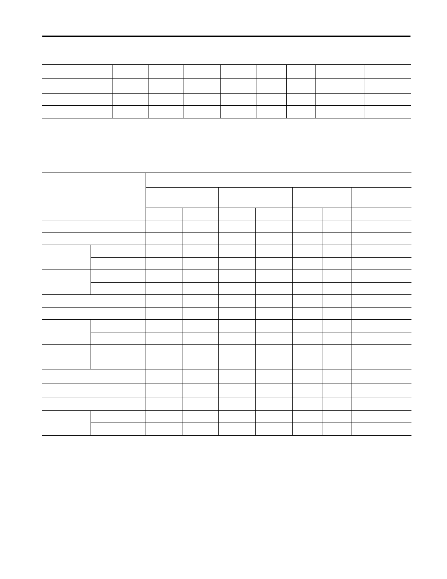
Table 7 1746-NR8 RTD Accuracy and Temperature Drift Specifications
Input Type
(1)
Accuracy
(4)
(0.25 mA Excitation)
Accuracy
(1.0 mA Excitation)
Temperature Drift
(5)
(0.25 mA Excitation)
Temperature Drift
(1.0 mA Excitation)
Platinum (385)
100
Ω
±0.5°C
(±0.9°F)
±0.7°C
(±1.3°F)
±0.012°C/°C
(±0.012°F/°F)
±0.020°C/°C
(±0.020°F/°F)
200
Ω
±0.6°C
(±1.1°F)
±0.7°C
(±1.3°F)
±0.015°C/°C
(± 0.015°F/°F)
±0.020°C/°C
(±0.020°F/°F)
500
Ω
±0.7°C
(±1.3°F)
±0.5°C
(± 0.9°F)
±0.020°C/°C
(±0.020°F/°F)
±0.012°C/°C
(±0.012°F/°F)
1000
Ω
±1.2°C
(±2.2°F)
±0.4°C
(±0.7°F)
±0.035°C/°C
(±0.035°F/°F)
±0.010°C/°C
(±0.010°F/°F)
Platinum (3916)
10
Ω
±0.4°C
(±0.7°F)
±0.6°C
(±1.1°F)
±0.010°C/°C
(± 0.010°F/°F)
±0.015°C/°C
(±0.015°F/°F)
200
Ω
±0.5°C
(±0.9°F)
±0.6°C
(±1.1°F)
±0.011°C/°C
(±0.011°F/°F)
±0.015°C/°C
(±0.015°F/°F)
500
Ω
±0.6°C
(±1.1°F)
±0.4°C
(±0.7°F)
±0.015°C/°C
(± 0.015°F/°F)
±0.012°C/°C
(±0.012°F/°F)
1000
Ω
±0.9°C
(±1.6°F)
±0.3°C
(±0.6°F)
±0.026°C/°C
(±0.026°F/°F)
±0.010°C/°C
(±0.010°F/°F)
Copper (426)
(2)
10
Ω
±0.5°C
(±0.9°F)
±0.8°C
(±1.4°F)
±0.008°C/°C
(±0.008°F/F)
±0.008°C/°C
(±0.008°F/°F)
Nickel (618)
(3)
120
Ω
± 0.2°C
(±0.4°F)
±0.2°C
(±0.4°F)
±0.003°C/°C
(±0.003°F/°F)
±0.005°C/°C
(±0.005°F/°F)
Nickel (672)
120
Ω
±0.2°C
(±0.4°F)
±0.2°C
(±0.4°F)
±0.003°C/°C
(±0.003°F/°F)
±0.005°C/°C
(±0.005°F/°F)
Nickel Iron (518)
604
Ω
±0.3°C
(±0.5°F)
±0.3°C
(± 0.5°F)
±0.008°C/°C
(±0.008°F/°F)
±0.008°C/°C
(±0.008°F/°F)
(1) The digits following the RTD type represent the temperature coefficient of resistance (
α
), which is defined as the resistance change per ohm per °C. For instance,
Platinum
385 refers to a platinum RTD with
α
= 0.00385 ohms/ohm-°C, or simply 0.00385/°C.
(2) Actual value at 0°C is 9.042
Ω
per SAMA standard RC21-4-1966.
(3) Actual value at 0°C is 100
Ω
per DIN standard.
(4) The accuracy value assumes that the module was calibrated with in the specified temperature range of 0°C to +60°C (+32°F to +140°F).
(5) Temperature drift specifications apply to a module that has not been calibrated.

Publication 1746-TD007B-EN-P - August 2000
10
SLC 500™ RTD/Resistance Input Modules
Table 8 1746-NR4 Resistance Input Specifications
Resistance
Resistance Range
(0.5 mA Excitation)
Resistance Range
(2.0 mA Excitation)
Accuracy
(1)
Temperature Drift
Resolution
Repeatability
150
Ω
0
Ω
to 150
Ω
0
Ω
to 150
Ω
±0.2
Ω
at 0.5 mA
±0.15
Ω
at 2.0 mA
±0.006
Ω
/°C at 0.5 mA
±0.004
Ω
/°C at 2.0 mA
0.01
Ω
±0.04
Ω
500
Ω
0
Ω
to 500
Ω
0
Ω
to 500
Ω
±0.5
Ω
±0.014
Ω
/°C
(±0.025
Ω
/°F)
0.1
Ω
±0.2
Ω
1000
Ω
0
Ω
to 1000
Ω
0
Ω
to 1000
Ω
±1.0
Ω
±0.029
Ω
/°C
(±0.052
Ω
/°F)
0.1
Ω
±0.2
Ω
3000
Ω
0
Ω
to 3000
Ω
0
Ω
to 1900
Ω
±1.5
Ω
±0.043
Ω
/°C
(±0.077
Ω
/°F)
0.1
Ω
±0.2
Ω
(1) The accuracy values assume that the module was calibrated within the specified temperature range of 0°C to 60°C (32°F to 140°F).
Table 9 1746-NR8 Resistance Input Specifications
Resistance Resistance Range
(0.25 mA Excitation)
Resistance Range
(1.0 mA Excitation)
Accuracy
(1)
Temperature Drift
Resolution
Repeatability
150
Ω
0
Ω
to 150
Ω
0
Ω
to 150
Ω
0.2
Ω
at 0.25 mA
0.15
Ω
at 1.0 mA
±0.004
Ω
/°C
(±0.002
Ω
/°F)
(2)
0.01
Ω
± 0.04
Ω
500
Ω
0
Ω
to 500
Ω
0
Ω
to 500
Ω
± 0.5
Ω
± 0.012
Ω
/°C
(± 0.007
Ω
/°F)
0.1
Ω
± 0.2
Ω
1000
Ω
0
Ω
to 1000
Ω
0
Ω
to 1000
Ω
± 1.0
Ω
± 0.025
Ω
/°C
(± 0.014
Ω
/°F)
0.1
Ω
± 0.2
Ω
3000
Ω
0
Ω
to 3000
Ω
0
Ω
to 1200
Ω
± 1.5
Ω
± 0.040
Ω
/°C
(± 0.023
Ω
/°F)
0.1
Ω
± 0.2
Ω
(1) The accuracy values assume that the module was calibrated within the specified temperature range of 0°C to 60°C (32°F to 140°F).
(2) The temperature drift for 150
Ω
is dependent on the excitation current: 0.006
Ω
/°C at 0.25 mA and 0.004
Ω
at 1.0 mA
Publication 1746-TD007B-EN-P - August 2000
SLC 500™ RTD/Resistance Input Modules
11
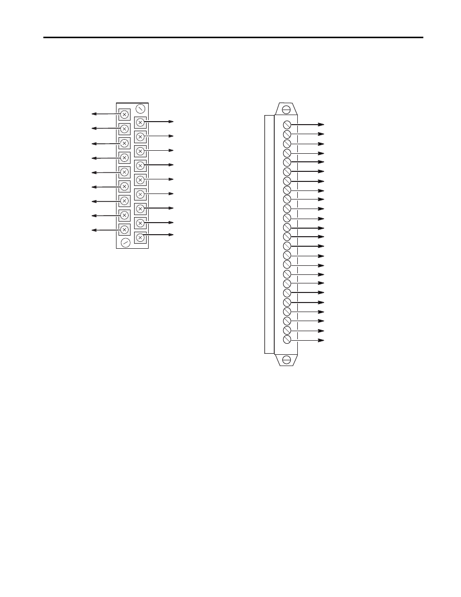
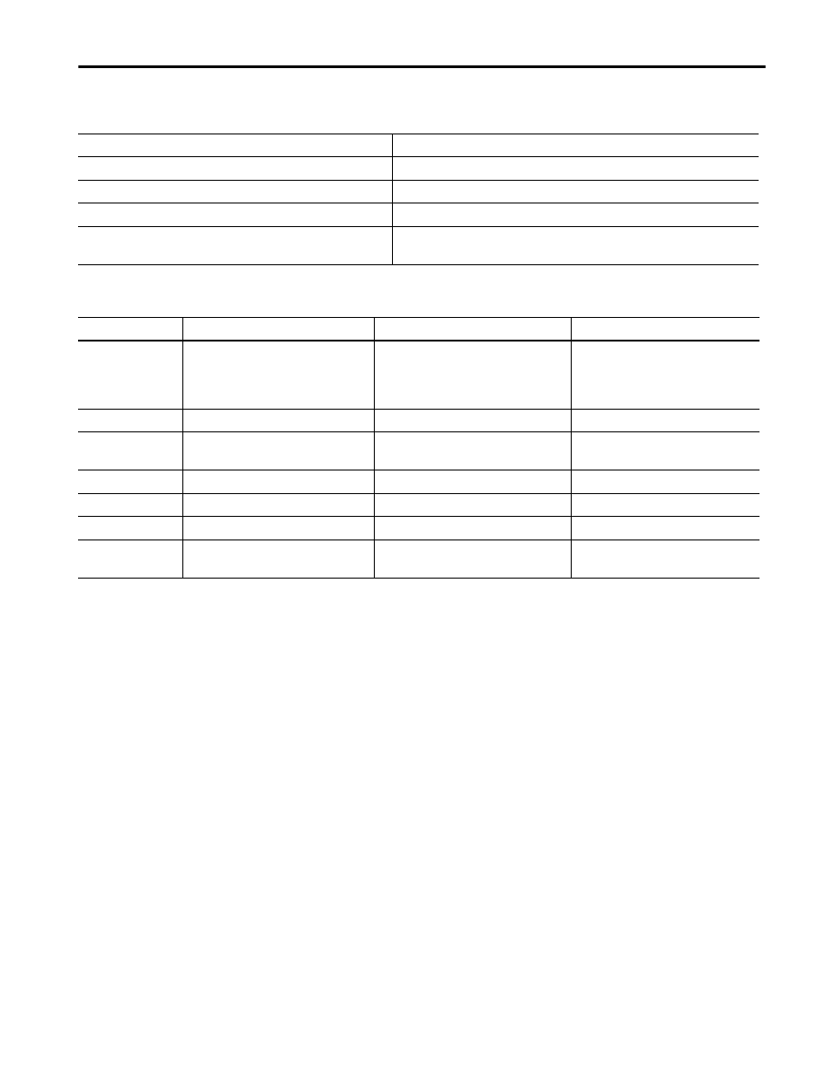
Module Wiring
The RTD input modules contain removable terminal blocks, as shown
below.
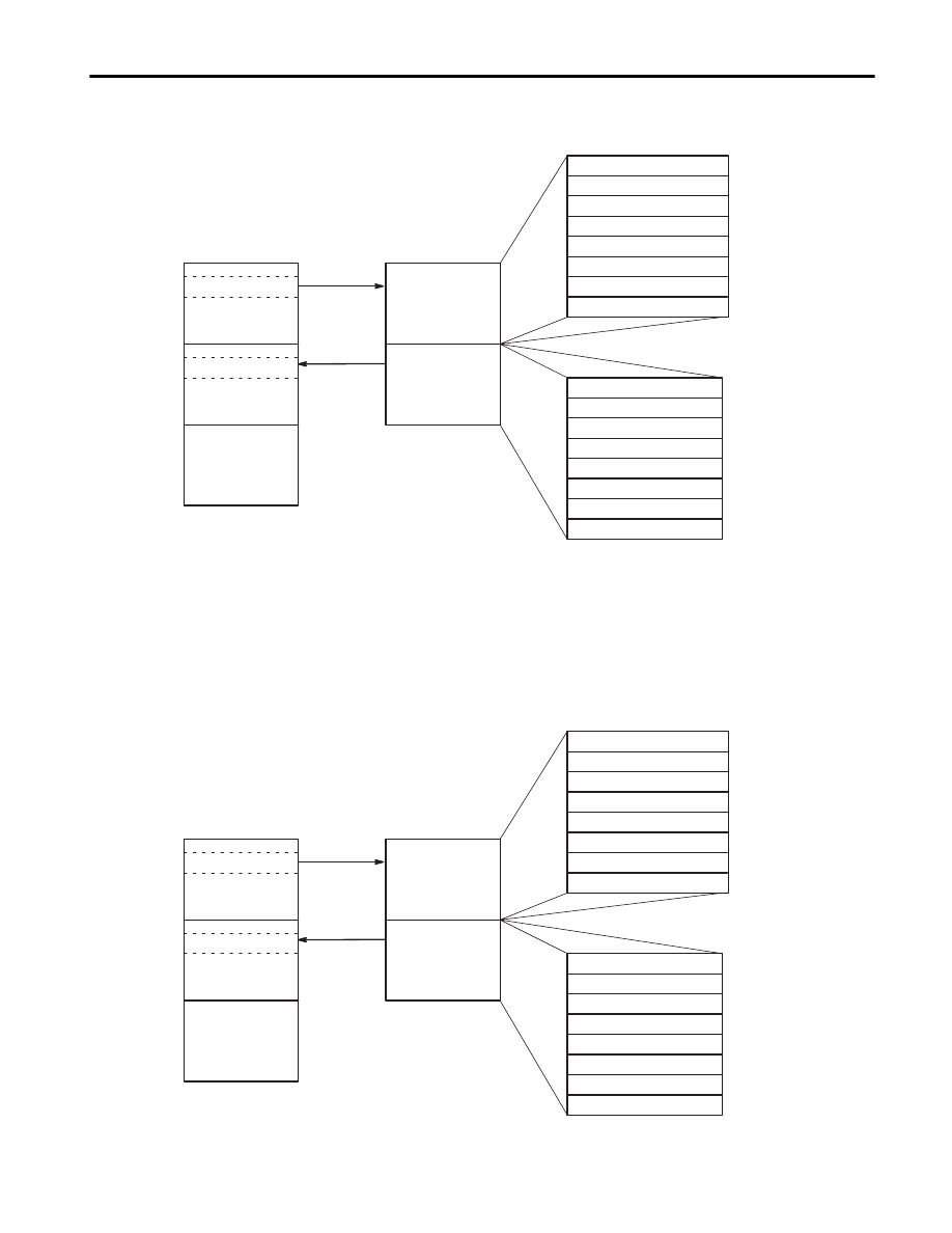
Module Addressing
The 1746-NR4 uses eight input words and eight output words, as
shown in the memory map on page 12.
Shield
Shield
Shield
Shield
Shield
Shield
Channel 0 RTD
Channel 2 RTD
Channel 3 RTD
Channel 1 RTD
Channel 0 Sense
Channel 2 Sense
Channel 1 Sense
Channel 3 Sense
Channel 0 Return
Channel 2 Return
Channel 1 Return
Channel 3 Return
1746-NR4
1746-NR8
Channel 0 Sense
Channel 0 Return
Channel 1 RTD
Channel 1 Sense
Channel 1 Return
Channel 2 RTD
Channel 2 Sense
Channel 2 Return
Channel 3 RTD
Channel 3 Sense
Channel 3 Return
Channel 4 RTD
Channel 4 Sense
Channel 4 Return
Channel 5 RTD
Channel 5 Sense
Channel 5 Return
Channel 6 RTD
Channel 6 Sense
Channel 6 Return
Channel 7 RTD
Channel 7 Sense
Channel 7 Return
Channel 0 RTD
Publication 1746-TD007B-EN-P - August 2000
12
SLC 500™ RTD/Resistance Input Modules
Figure 10 1746-NR4 Memory Map
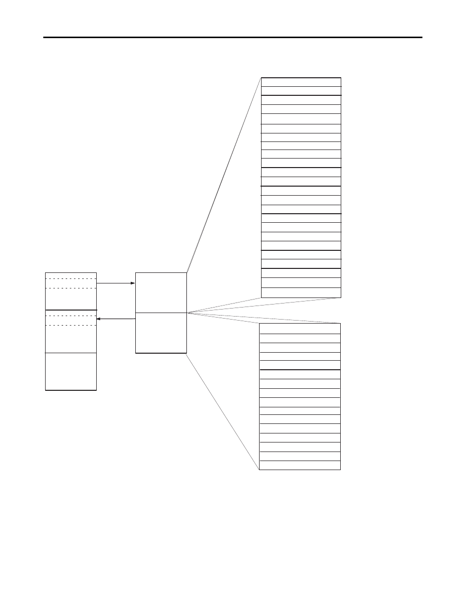
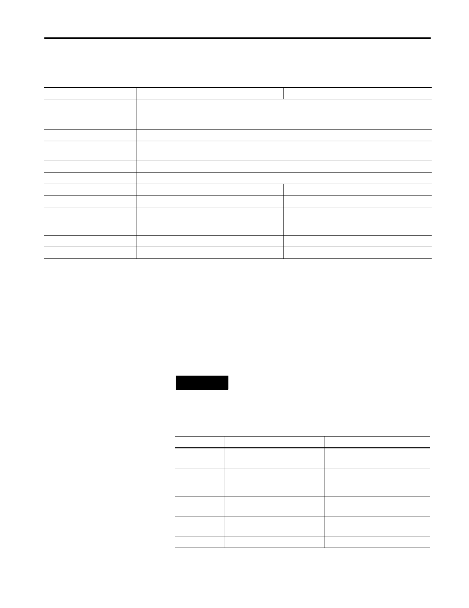
The 1746-NR8 has two operating modes, which determine how many
input and output words the module uses. In Class 1, the module uses
8 input and 8 output words. In Class 3, the module uses 16 input and
24 output words.
Figure 11 1746-NR8 Class 1 Memory Map
Channel 0 Configuration Word
Channel 2 Configuration Word
Channel 3 Configuration Word
Lower Scale Limit Range 0
Upper Scale Limit Range 0
Lower Scale Limit Range 1
Upper Scale Limit Range 1
Channel 1 Configuration Word
Channel 0 Data Word
Channel 1 Data Word
Channel 2 Data Word
Channel 3 Data Word
Channel 0 Status Word
Channel 1 Status Word
Channel 2 Status Word
Channel 3 Status Word
Word 0
Word 1
Word 2
Word 3
Word 4
Word 5
Word 6
Word 7
O:e.0
O:e.1
O:e.2
O:e.3
O:e.4
O:e.5
O:e.6
O:e.7
Word 0
Word 1
Word 2
Word 3
Word 4
Word 5
Word 6
Word 7
I:e.0
I:e.1
I:e.2
I:e.3
I:e.4
I:e.5
I:e.6
I:e.7
Address
Address
Bit 0
Bit 15
Bit 15
Bit 0
Output
Image
Input
Image
Analog Input
Module
Image Table
Output Image
8 Words
Input Image
8 Words
Output
Scan
Input
Scan
SLC 5/0X
Data Files
Slot e
Slot e
Output Image
Input Image
Channel 0 Configuration Word
Channel 2 Configuration Word
Channel 3 Configuration Word
Channel 4 Configuration Word
Channel 5 Configuration Word
Channel 6 Configuration Word
Channel 7 Configuration Word
Channel 1 Configuration Word
Channel 0 Data Word
Channel 1 Data Word
Channel 2 Data Word
Channel 3 Data Word
Channel 4 Data Word
Channel 5 Data Word
Channel 6 Data Word
Channel 7 Data Word
Word 0
Word 1
Word 2
Word 3
Word 4
Word 5
Word 6
Word 7
O:e.0
O:e.1
O:e.2
O:e.3
O:e.4
O:e.5
O:e.6
O:e.7
Word 0
Word 1
Word 2
Word 3
Word 4
Word 5
Word 6
Word 7
I:e.0
I:e.1
I:e.2
I:e.3
I:e.4
I:e.5
I:e.6
I:e.7
Address
Address
Bit 0
Bit 15
Bit 15
Bit 0
Output
Image
Input
Image
Analog Input
Module
Image Table
Output Image
8 Words
Input Image
8 Words
Output
Scan
Input
Scan
SLC 5/0X
Data Files
Slot e
Slot e
Output Image
Input Image
Publication 1746-TD007B-EN-P - August 2000
SLC 500™ RTD/Resistance Input Modules
13
Figure 12 1746-NR8 Class 3 Memory Map
Channel 0 Configuration Word
Channel 1 Configuration Word
Channel 2 Configuration Word
Channel 3 Configuration Word
Channel 4 Configuration Word
Channel 7 Configuration Word
Channel 6 Configuration Word
Channel 5 Configuration Word
lower scale limit range 0
lower scale limit range 1
lower scale limit range 2
lower scale limit range 3
lower scale limit range 4
lower scale limit range 5
lower scale limit range 6
lower scale limit range 7
upper scale limit range 0
upper scale limit range 1
upper scale limit range 2
upper scale limit range 3
upper scale limit range 4
upper scale limit range 5
upper scale limit range 6
upper scale limit range 7
Word 0
Word 1
Word 2
Word 3
Word 4
Word 5
Word 6
Word 7
Word 8
Word 9
Word 10
Word 11
Word 12
Word 13
Word 14
Word 15
Word 16
Word 17
Word 18
Word 19
Word 20
Word 21
Word 22
Word 23
O:e.0
O:e.1
O:e.2
O:e.3
O:e.4
O:e.5
O:e.6
O:e.7
O:e.8
O:e.9
O:e.10
O:e.11
O:e.12
O:e.13
O:e.14
O:e.15
O:e.16
O:e.17
O:e.18
O:e.19
O:e.20
O:e.21
O:e.22
O:e.23
Address
Bit 0
Bit 15
Bit 0
Bit 15
Word 0
Word 1
Word 2
Word 3
Word 4
Word 5
Word 6
Word 7
Word 8
Word 9
Word 10
Word 11
Word 12
Word 13
Word 14
Word 15
I:e.0
I:e.1
I:e.2
I:e.3
I:e.4
I:e.5
I:e.6
I:e.7
I:e.8
I:e.9
I:e.10
I:e.11
I:e.12
I:e.13
I:e.14
I:e.15
Address
Channel 0 Data Word
Channel 1 Data Word
Channel 2 Data Word
Channel 3 Data Word
Channel 4 Data Word
Channel 5 Data Word
Channel 6 Data Word
Channel 7 Data Word
Channel 0 Status Word
Channel 1 Status Word
Channel 2 Status Word
Channel 3 Status Word
Channel 4 Status Word
Channel 5 Status Word
Channel 6 Status Word
Channel 7 Status Word
Output Image
Input Image
Analog Input
Module
Image Table
Output Image
24 Words
Input Image
16 Words
Output
Scan
Input
Scan
SLC 5/0X
Data Files
Slot e
Slot e
Output Image
Input Image

Publication 1746-TD007B-EN-P - August 2000
14
SLC 500™ RTD/Resistance Input Modules
Channel Data and Status (Input Image)
Data words hold the input data that represent the temperature value
of RTD analog inputs or the resistance value of resistive inputs for
each channel. The data word is valid only when the channel is
enabled and there are no channel errors.
Status words contain the status of each channel. The status bits for a
particular channel reflect the configuration settings that you have
entered into the output image configuration word for that channel, as
well as providing information about the channel’s operational state.
To receive valid status information the channel must be enabled, and
the channel must have processed any configuration changes that may
have been made to the configuration word.
Channel Configuration (Output Image)
Once the module has been installed, each channel on the module can
be configured to establish the way the channel will operate. You
configure the channel by entering bit values into the configuration
word using your programming software. Channels 0-3 on the
1746-NR4 module are configured by entering bit values into output
words 0-3, respectively. Similarly, channels 0-7 on the 1746-NR8
module are configured by entering bit values into output words 0-7,
respectively.
Output words 4-7 on the 1746-NR4 are used for scaling purposes.
Output words 8 through 23 (Class 3 only) on the 1746-NR8 are also
used for scaling.
Publication 1746-TD007B-EN-P - August 2000
SLC 500™ RTD/Resistance Input Modules
15
You can configure the following parameters:
1746-NR8 Class 1 or Class 3 Operation
The 1746-NR8 module can be configured for Class 1 or Class 3
operation. The table below explains the difference between the
classes.
Table 13 Configurable Parameters
Parameter
1746-NR4
1746-NR8
RTD Type
(1)
100
Ω,
200
Ω,
500
Ω,
1000
Ω
Platinum (385)
10
Ω
Copper (426)
(2)
120
Ω
Nickel (672)
100
Ω,
200
Ω,
500
Ω,
1000
Ω
Platinum (3916)
120
Ω
Nickel (618)
(3)
604
Ω
Nickel/Iron (518)
Resistance Device Type
150, 500, 1000, or 3000 ohm
Data Format
1.0 degree, 0.1 degrees, 1 ohm, 0.1 ohms, 0.01 ohms (for 150 ohm range only), proportional counts, or
scaled-for-PID
Open /Short Circuit
Zero, upscale, or downscale
Temperature Units
°C or °F
Filter Frequency
10 Hz, 50 Hz, 60 Hz, or 250 Hz
28 Hz, 50/60 Hz, 800 Hz, or 6400 Hz
RTD Excitation Current
0.5 mA or 2.0 mA
0.25 mA or 1.0 mA
Scaling
Scaled-for-PID: 0 to 16383
Proportional Counts: -32768 to +32767
User-defined: 2 ranges (lower/upper)
Scaled-for-PID: 0 to 16383
Proportional Counts: -32768 to +32767
User-defined: 2 ranges (lower/upper)
Periodic Calibration
Not configurable
Enable or Disable
Lead Resistance Measurement Not configurable
Disable, periodic, or always
(1) The digits in parenthesis following the RTD type represent the temperature coefficient of resistance (
α
) that is defined as the resistance change per ohm per °C. For
instance, Platinum 385 refers to a platinum RTD with
α
= 0.00385 ohms/ohm-°C, or simply 0.00385.°C.
(2) Actual value at 0°C is 9.042
Ω
per SAMA standard RC21-4-1966.
(3) Actual value at 0°C is 100
Ω
per DIN standard.
NOTE
The 1746-NR4 module operates only in Class 1.
See Figure 10 on page 12 for the 1746-NR4 memory
map.
Table 14 Class 1 vs. Class 3 Operation
Configuration Class 1
Class 3
Compatible
SLC Processors
SLC 500 fixed, SLC 5/01 and
higher
SLC 5/02 and higher
Compatible
Chassis
local chassis or remote chassis
with 1747-ASB Adapter
(1)
(1) Requires use of Block Transfer in a remote configuration.
local chassis or remote chassis with
a 1747-ACN(R)15 ControlNet
Adapter
1746-NR8
Input Image
8 channel data words
8 channel data words
8 channel status words
1747-NR8
Output Image
8 channel configuration words
8 channel configuration words
16 words for user-set scaling
Default
Class 1 is the default on power-up Class 3 is programmable by the user
Publication 1746-TD007B-EN-P - August 2000
16
SLC 500™ RTD/Resistance Input Modules
Data Format
The format of the data that the RTD module sends back to the SLC
processor depends on how the bits are set in the configuration word.
Specific bit fields represent various channel characteristics. Each of
these characteristics can be modified from its power-up default setting
at any time while the module is operating.
Specific bit settings are discussed in the 1746-NR4 SLC 500™
RTD/Resistance Input Module User’s Manual (publication number
1746-6.7) and 1746-NR8 SLC 500™ RTD/Resistance Input Module
User’s Manual (publication number 1746-UM003A-EN-P).
The tables on pages 16 through 20 define the data formats and the
resolutions that can be represented for each input type.
In these tables:
•
Engineering Units provide the input value directly in °C, °F, or
ohms.
•
Scaled-for-PID provides a data format directly compatible with
the SLC 5/02, SLC 5/03, SLC 5/04, and SLC 5/05 PID algorithm. It
also requires manual conversion to engineering units.
•
Proportional Counts provide the greatest possible resolution
but require manual conversion to engineering units in your
control program.
Table 15 1746-NR4 Data Formats for RTD Temperature Ranges
RTD Input Type
Data Format Using 0.5 and 2.0 mA Excitation Current
Engineering Units x 1
Engineering Units x 10
Scaled-for-PID
Proportional
Counts
(Default)
0.1°C
0.1°F
1.0°C
1.0°F
100
Ω
Platinum (385)
-2000 to +8500
-3280 to +15620
-200 to +850
-328 to +1562
0 to 16383
-32768 to 32767
200
Ω
Platinum (385)
-2000 to +8500
-3280 to +15620
-200 to +850
-328 to +1562
0 to 16383
-32768 to 32767
500
Ω
Platinum (385)
-2000 to +8500
-3280 to +15620
-200 to +850
-328 to +1562
0 to 16383
-32768 to 32767
100
Ω
Platinum (3916)
-2000 to +6300
-3280 to +11660
-200 to +630
-328 to +1166
0 to 16383
-32768 to 32767
200
Ω
Platinum (3916)
-2000 to +6300
-3280 to +11660
-200 to +630
-328 to +1166
0 to 16383
-32768 to 32767
500
Ω
Platinum (3916)
-2000 to +6300
-3280 to +11660
-200 to +630
-328 to +1166
0 to 16383
-32768 to 32767
120
Ω
Nickel (672)
-800 to +2600
-1120 to +5000
-80 to +260
-112 to +500
0 to 16383
-32768 to 32767
120
Ω
Nickel (618)
(1)
-1000 to +2600
-1480 to +5000
-100 to +260
-148 to +500
0 to 16383
-32768 to 32767
604
Ω
Nickel/Iron (518)
-1000 to +2000
-1480 to +3920
-100 to +200
-148 to +392
0 to 16383
-32768 to 32767
10
Ω
Copper (426)
(2)
at 2.0 mA only
(3)
-1000 to +2600
-1480 to +5000
-100 to +260
-148 to +500
0 to 16383
-32768 to 32767
(1) Actual value at 0°C is 100
Ω
per DIN standard.
(2) Actual value at 0°C is 9.042
Ω
per SAMA standard RC21-4-1966.
(3) 0.5 excitation current is not allowed.
Publication 1746-TD007B-EN-P - August 2000
SLC 500™ RTD/Resistance Input Modules
17
Table 16 1746-NR8 Data Formats for RTD Temperature Ranges
RTD Input Type
Data Format Using 0.25 and 1.0 mA Excitation Current
Engineering Units x 1
Engineering Units x 10
Scaled-for-PID
Proportional
Counts
(Default)
0.1°C
0.1°F
1.0°C
1.0°F
100
Ω
Platinum (385)
-2000 to +8500
-3280 to +15620
-200 to +850
-328 to +1562
0 to 16383
-32768 to 32767
200
Ω
Platinum (385)
-2000 to +6300
-3280 to + 6300
-200 to +630
-328 to +630
0 to 16383
-32768 to 32767
100
Ω
Platinum (3916)
-2000 to +6300
-3280 to +6300
-200 to +630
-328 to +630
0 to 16383
-32768 to 32767
200
Ω
Platinum (3916)
-2000 to +6300
-3280 to +6300
-200 to +630
-328 to +630
0 to 16383
-32768 to 32767
120
Ω
Nickel (672)
-800 to +2600
-3280 to +5000
-80 to +260
-328 to +500
0 to 16383
-32768 to 32767
120
Ω
Nickel (618)
(1)
-1000 to +2600
-3280 to +5000
-100 to +260
-328 to +500
0 to 16383
-32768 to 32767
604
Ω
Nickel/Iron (518)
at 0.25 mA only
-2000 to +2000
-3280 to +3920
-200 to +200
-328 to +392
0 to 16383
-32768 to 32767
604
Ω
Nickel/Iron (518)
at 1.0 mA only
-2000 to +1800
-3280 to +3380
-200 to +180
-328 to +338
0 to 16383
-32768 to 32767
10
Ω
Copper (426)
(2)
-1000 to +2600
-3280 to +5000
-100 to +260
-328 to +500
0 to 16383
-32768 to 32767
(1)
Actual value at 0°C is 100
Ω
per DIN standard.
(2) Actual value at 0°C is 9.042
Ω
per SAMA standard RC21-4-1966.
Table 17 Data Format for 1000
Ω
Platinum RTD Input Type
Module
RTD
Input
Type
Excitation
Current
Data Format
Engineering Units x 1
Engineering Units x 10
Scaled-
for-PID
Proportional
Counts
(Default)
0.1°C
0.1°F
1.0°C
1.0°F
1746-NR4
Platinum
(385)
0.5 mA
-2000 to +8500
-3280 to +15620
-200 to +850
-328 to +1562
0 to 16383
-32768 to 32767
2.0 mA
-2000 to +2400
-3280 to +4640
-200 to +240
-328 to +464
0 to 16383
-32768 to 32767
Platinum
(3916)
0.5 mA
-2000 to +6300
-3280 to +11660
-200 to +630
-328 to +1166
0 to 16383
-32768 to 32767
2.0 mA
-2000 to +2300
-3280 to +44600
-200 to +230
-328 to +446
0 to 16383
-32768 to 32767
1746-NR8
Platinum
(385)
0.25 mA
-2000 to +8500
-3280 to +15620
-200 to +850
-328 to +1562
0 to 16383
-32768 to 32767
1.0 mA
-2000 to +500
-3280 to +1220
-200 to +50
-328 to +122
0 to 16383
-32768 to 32767
Platinum
(3916)
0.25 mA
-2000 to +6300
-3280 to +11660
-200 to +630
-328 to +1166
0 to 16383
-32768 to 32767
1.0 mA
-2000 to +500
-3280 to +1220
-200 to +50
-328 to +122
0 to 16383
-32768 to 32767
Publication 1746-TD007B-EN-P - August 2000
18
SLC 500™ RTD/Resistance Input Modules
Table 18 Data Format for 500
Ω
Platinum RTD Input Type
Module
RTD
Input
Type
Excitation
Current
Engineering Units x 1
Engineering Units x 10
Scaled-
for-PID
Proportional
Counts
(Default)
0.1°C
0.1°F
1.0°C
1.0°F
1746-NR4
Platinum
(385)
0.5 mA
-2000 to +8500
-3280 to +15620 -200 to +850
-328 to +1562 0 to 16383
-32768 to 32767
2.0 mA
Platinum
(3916)
0.5 mA
-2000 to +6300
-3280 to +11660 -200 to +630
-328 to +1166 0 to 16383
-32768 to 32767
2.0 mA
1746-NR8
Platinum
(385)
0.25 mA
-2000 to +8500
-3280 to +15620 -200 to +850
-328 to +1562 0 to 16383
-32768 to 32767
1.0 mA
-2000 to +3900
-3280 to +6980
-200 to +390
-328 to +698
0 to 16383
-32768 to 32767
Platinum
(3916)
0.25 mA
-2000 to +6300
-3280 to +11660 -200 to +630
-328 to +1166 0 to 16383
-32768 to 32767
1.0 mA
-2000 to +3800
-3280 to +6980
-200 to +380
-328 to +698
0 to 16383
-32768 to 32767
Table 19 Data Format for Resistance Inputs
Module
Resistance Input Type
Data Format
Engineering Units x 1
Engineering Units x 10 Scaled-for-PID Proportional
Counts (Default)
0.01 Ohms
0.1 Ohms
(1)
Both
150
Ω
0 to 15000
0 to 1500
0 to 16383
-32768 to 32767
500
Ω
0 to 5000
0 to 500
0 to 16383
-32768 to 32767
1000
Ω
0 to 10000
0 to 1000
0 to 16383
-32768 to 32767
1746-NR4
3000
Ω
0.5 mA excitation
0 to 30000
0 to 3000
0 to 16383
-32768 to 32767
2.0 mA excitation
0 to 19000
0 to 1900
0 to 16383
-32768 to 32767
1746-NR8
3000
Ω
0.25 mA excitation 0 to 30000
0 to 3000
0 to 16383
-32768 to 32767
1.0 mA excitation
0 to 12000
0 to 1200
0 to 16383
-32768 to 32767
(1) When ohms are selected, the temperature-units selection (bit 8) is ignored. Analog input data is the same for either °C or °F selection.
Table 20 1746-NR4 Channel Data Word Resolution for RTDs
RTD Input Type
Data Format (Bits 4 and 5)
(3)
Engineering Units x 1
Engineering Units x 10 Scaled-for-PID
Proportional Counts (Default)
° C/step
° F/step
° C/step
° F/step
° C/step
° F/step ° C/step
° F/step
100
Ω
Platinum 385
0.1
0.1
1.0
1.0
0.0641
0.1154
0.0160
0.0288
200
Ω
Platinum 385
0.1
0.1
1.0
1.0
0.0641
0.1154
0.0160
0.0288
500
Ω
Platinum 385
0.1
0.1
1.0
1.0
0.0641
0.1154
0.0160
0.0288
1000
Ω
Platinum 385
0.1
0.1
1.0
1.0
0.0641
0.1154
0.0160
0.0288
100
Ω
Platinum 3916
0.1
0.1
1.0
1.0
0.0507
0.0912
0.012 7
0.0228
200
Ω
Platinum 3916
0.1
0.1
1.0
1.0
0.0507
0.0912
0.0127
0.0228
500
Ω
Platinum 3916
0.1
0.1
1.0
1.0
0.0507
0.0912
0.0127
0.0228
1000
Ω
Platinum 3916
0.1
0.1
1.0
1.0
0.0507
0.0912
0.0127
0.0228
Publication 1746-TD007B-EN-P - August 2000
SLC 500™ RTD/Resistance Input Modules
19
10
Ω
Copper 426
(1)
0.1
0.1
1.0
1.0
0.0220
0.0396
0.0051
0.0099
120
Ω
Nickel 618
(2)
0.1
0.1
1.0
1.0
0.0220
0.0396
0.0051
0.0099
120
Ω
Nickel 672
0.1
0.1
1.0
1.0
0.0208
0.0374
0.0052
0.0093
604
Ω
Nickel/Iron 518
0.1
0.1
1.0
1.0
0.0183
0.0330
0.0046
0.0082
(1) Actual value at 0°C is 9.042
Ω
per SAMA standard RC21-4-1966.
(2) Actual value at 0°C is 100
Ω
standard.
(3) When ohms are selected, the temperature-units selection (bit 8) is ignored. Analog input data is the same for either °C or °F selection.
Table 20 1746-NR4 Channel Data Word Resolution for RTDs
Table 21 1746-NR8 Channel Data Word Resolution for RTDs
RTD Input Type
Data Format (Bits 4 and 5)
(3)
Engineering Units x 1
Engineering Units x 10
Scaled-for-PID
Proportional
Counts (Default)
° C/step
° F/step
° C/step
° F/step
° C/step
° F/step
° C/step
° F/step
100
Ω
Platinum 385
0.1
0.1
1.0
1.0
0.0641
0.1154
0.0160
0.0288
200
Ω
Platinum 385
0.1
0.1
1.0
1.0
0.0641
0.1154
0.0160
0.0288
500
Ω
Platinum
385
0.25 mA excitation 0.1
0.1
1.0
1.0
0.0641
0.1154
0.0160
0.0288
1.0 mA excitation
0.1
0.1
1.0
1.0
0.0360
0.0648
0.0090
0.0162
1000
Ω
Platinum 385
0.25 mA excitation 0.1
0.1
1.0
1.0
0.0641
0.1154
0.0160
0.0288
1.0 mA excitation
0.1
0.1
1.0
1.0
0.0153
0.10275
0.0038
0.0069
100
Ω
Platinum 3916
0.1
0.1
1.0
1.0
0.0507
0.0912
0.0127
0.0228
200
Ω
Platinum 3916
0.1
0.1
1.0
1.0
0.0507
0.0912
0.0127
0.0228
500
Ω
Platinum
3916
0.25 mA excitation 0.1
0.1
1.0
1.0
0.0507
0.0912
0.0127
0.0228
1.0 mA excitation
0.1
0.1
1.0
1.0
0.0354
0.0637
0.0089
0.0159
1000
Ω
Platinum 3916
0.25 mA excitation 0.1
0.1
1.0
1.0
0.0507
0.0912
0.0127
0.0228
1.0 mA excitation
0.1
0.1
1.0
1.0
0.0153
0.0275
0.0038
0.0104
10
Ω
Copper 426
(1)
0.1
0.1
1.0
1.0
0.0220
0.0396
0.0051
0.0099
120
Ω
Nickel 618
(2)
0.1
0.1
1.0
1.0
0.0220
0.0396
0.0051
0.0099
120
Ω
Nickel 672
0.1
0.1
1.0
1.0
0.0208
0.0374
0.0052
0.0093
604
Ω
Nickel/Iron 518
0.25 mA excitation 0.1
0.1
1.0
1.0
0.0183
0.0330
0.0046
0.0082
1.0 mA excitation
0.1
0.1
1.0
1.0
0.0232
0.0417
0.0058
0.0104
(1) Actual value at 0°C is 9.042
Ω
per SAMA standard RC21-4-1966.
(2) Actual value at 0°C is 100
Ω
standard.
(3) When ohms are selected, the temperature-units selection (bit 8) is ignored. Analog input data is the same for either °C or °F selection.
Publication 1746-TD007B-EN-P - August 2000
20
SLC 500™ RTD/Resistance Input Modules
Module Diagnostics
The RTD module performs operations at two levels:
•
module-level operations
•
channel-level operations
Module-level operations include functions such as power-up
configuration and communication with the SLC processor.
Channel-level operations describe channel-related functions, such as
data conversion and out-of-range or open-circuit or short-circuit
(RTDs only) detection.
Internal diagnostics are performed at both levels of operation and any
error conditions detected are immediately indicated by the module’s
LEDs and status to the SLC processor.
Power-Up Diagnostics
At module power-up, a series of internal diagnostic tests is performed.
If any diagnostic test fails, the module enters the module error state. If
all tests pass, the module initializes its hardware and software
environment and turns on the module status LED. During power-up,
the RTD module does not communicate with the processor.
Channel Diagnostics
When a channel is enabled (bit 11 = 1), a diagnostic check is
performed to see that the channel is properly configured. In addition,
the channel is tested for out-of-range, open-circuit, and short-circuit
faults on every scan.
A failure of any channel diagnostic test causes the faulted channel
status LED to blink. All channel faults are indicated in bits 13 through
15 of the channel’s status word. Channel faults are self-clearing when
the fault conditions are corrected, and the channel LED will stop
blinking and resume steady illumination when the fault conditions are
corrected.
Table 22 Channel Data Word Resolution for Resistance Inputs
Resistance
Input Type
Data Format (Bits 4 and 5)
Engineering Units x 1
Engineering Units x 10
Scaled-for-PID
Proportional Counts (Default)
Ohms/step
Ohms/step
Ohms/step
Ohms/step
150
Ω
0.01
0.1
0.0092
0.0023
500
Ω
0.1
1
0.0305
0.0076
1000
Ω
0.1
1
0.0610
0.0153
3000
Ω
0.1
1
0.1831
0.0458
Publication 1746-TD007B-EN-P - August 2000
SLC 500™ RTD/Resistance Input Modules
21
Specifications
1746-NR4
1746-NR8
Backplane Current Consumption
50 mA at 5V dc
50 mA at 24V dc
100 mA at 5V dc
55 mA at 24V dc
Backplane Power Consumption
1.5W maximum
(0.3 W at 5V dc, 1.2 W at 24V dc)
1.82W maximum
(0.5W at 5V dc, 1.32W at 24V dc)
External Power Supply Requirements None
Number of Channels
4 (backplane isolated)
8 (backplane isolated)
I/O Chassis Location
Any I/O module slot except slot 0
A/D Conversion Method
Sigma-Delta Modulation
Input Filtering
Low pass digital filter with programmable notch (filter) frequencies
Common Mode Rejection (between
inputs and chassis ground)
> 150 dB at 50 Hz (10 Hz and 50 Hz filter
frequencies)
> 150 dB at 60 Hz (10 Hz and 60 Hz filter
frequencies)
> 120 dB at 50 Hz (28 Hz and 50 Hz filter
frequencies)
> 120 dB at 60 Hz (28 Hz and 60 Hz filter
frequencies)
Normal Mode Rejection (between [+]
input and [-] input)
Greater than 100 dB at 50 Hz (10 Hz, 50 Hz filter
frequencies)
Greater than 100 dB at 60 Hz (10 Hz, 60 Hz filter
frequencies)
65 dB at 50/60 Hz (with 50/60 Hz filter)
110 dB at 50 Hz (with 28 Hz filter)
95 dB at 60 Hz (with 28 Hz filter)
Maximum common mode voltage
± 1 volt
Maximum allowed permanent
overload
(1)
Volts: ± 5V dc
Current: ± 5mA
Input Filter Cut-Off Frequencies
2.62 Hz at 10 Hz filter frequency
13.1 Hz at 50 Hz filter frequency
15.72 Hz at 60 Hz filter frequency
65.5 Hz at 250 Hz filter frequency
7.80 Hz at 28 Hz filter frequency
13.65 Hz at 50/60 Hz filter frequency
209.6 Hz at 800 Hz filter frequency
1676 Hz at 6400 Hz filter frequency
Calibration
Module autocalibrates when power is applied, a
channel is enabled or when a change is made to
its input type, filter frequency, or excitation
current.
Set module calibration disable to zero to enable
module to autocalibrate when power is applied,
a channel is enabled, or when a change is made
to the input type, filter frequency, or excitation
current.
Isolation (optical)
500V dc continuous between inputs and chassis
ground, and between inputs and backplane
707V dc for 1 minute
Isolation Between Inputs
None
±5V dc
(1) Do not apply a voltage or current to the module.
Table 23 Physical Specifications
1746-NR4
1746-NR8
LED Indicators
green status indicators, one for each channel and one for module status
Module ID Code
3513
Class 1: 3508
Class 3: 12708
Maximum Termination Wire Size
Two 14 AWG wire per terminal
One 14 AWG wire per terminal
Maximum Cable Impedance
25
ohms maximum impedance for 3-wire RTD configuration (see Cable Specifications)
Removable Terminal Block
1746-RT25G
1746-RT35
Publication 1746-TD007B-EN-P - August 2000
22
SLC 500™ RTD/Resistance Input Modules
Table 24 Environmental Specifications
Operating Temperature
0°C to +60°C (+32°F to+140°F)
Storage Temperature
−
40°C to
+
85°C (
−
104°F to
+
185°F)
Relative Humidity
5% to 95% (without condensation)
Hazardous Environment Classification
Class I, Division 2 Hazardous Environment
Agency Certification (when product or packaging is marked)
•UL and CSA Class I Division 2 Groups A,B,C,D certified
•CE compliant for all applicable directives
Table 25 Cable Specifications
Description
Belden #9501
Belden #9533
Belden #83503
When used?
For 2-wire RTDs and potentiometers. For 3-wire RTDs and potentiometers.
Short runs less than 100 feet and
normal humidity levels.
For 3-wire RTDs and
potentiometers. Long runs greater
than 100 feet or high humidity
levels.
Conductors
2, #24 AWG tinned copper (7× 32)
3, #24 AWG tinned copper (7× 32)
3, #24 AWG tinned copper (7× 32)
Shield
Beldfoil aluminum polyester shield
with copper drain wire.
Beldfoil aluminum polyester shield
with copper drain wire.
Beldfoil aluminum polyester shield
with tinned braid shield.
Insulation
PVC
S-R PVC
Teflon
Jacket
Chrome PVC
Chrome PVC
Red teflon
Agency Approvals
NEC Type CM
NEC Type CM
NEC Art-800, Type CMP
Temperature
Rating
+80°C
+80°C
+200°C

Publication 1746-TD007B-EN-P - August 2000
SLC 500™ RTD/Resistance Input Modules
23
Table 26 Input Specifications
1746-NR4
1746-NR8
RTD Type:
(Temperature
Range
Independent
of Excitation
Current)
100
Ω
Platinum (385) -200°C to +850°C (-328°F to +1562°F)
200
Ω
Platinum (385) -200°C to +850°C (-328°F to +1562°F)
500
Ω
Platinum (385) -200°C to +850°C (-328°F to +1562°F)
100
Ω
Platinum (3916) -200°C to +630°C (-328°F to+1166°F)
200
Ω
Platinum (3916) -200°C to +630°C (-328°F to+1166°F)
500
Ω
Platinum (3916) -200°C to +630°C (-328°F to+1166°F)
120
Ω
Nickel (618)
(2)
-100°C to +260°C (-148°F to +500°F)
120
Ω
Nickel (672) -80°C to +260°C (-112°F to +500°F)
604
Ω
Nickel/Iron (518) -100°C to +200°C (-148°F to +392°F)
100
Ω
Platinum (385) -200°C to +850°C (-328°F to +1562°F)
200
Ω
Platinum (385) -200°C to +850°C (-328°F to +1562°F)
100
Ω
Platinum (3916) -200°C to +630°C (-328°F to+1166°F)
200
Ω
Platinum (3916) -200°C to +630°C (-328°F to+1166°F)
120
Ω
Nickel (618)
(4)
-100°C to +260°C (-148°F to +500°F)
120
Ω
Nickel (672) -80°C to +260°C (-112°F to +500°F)
10
Ω
(5)
Copper (426) -100°C to +260°C (-328°F to +500°F)
RTD Type:
(Temperature
Range
Dependent
of Excitation
Current)
(1)
1000
Ω
Platinum (385):
-200°C to +850°C (-328°F to +1562°F) for 0.5 mA excitation.
-200°C to +240°C (-328°F to +464°F) for 2.0 mA excitation.
1000
Ω
Platinum (3916):
-200°C to +630°C (-328°F to+1166°F) for 0.5 mA excitation.
-200°C to +230°C (-328°F to +446°F) for 2.0 mA excitation.
10
Ω
(3)
Copper (426):
-100°C to +260°C (-148°F to +500°F) for 2.0 mA excitation.
Important: 0.5 mA excitation current is not allowed for this
RTD.
500
Ω
Platinum (385):
-200°C to +850°C (-328°F to +1562°F) for 0.25 mA excitation
-200°C to +390°C (-328°F to +698°F) for 1.0 mA excitation
500
Ω
Platinum (3916):
-200°C to +630°C (-328°F to+1166°F) for 0.25 mA excitation
-200°C to +380°C (-328°F to +698°F) for 1.0 mA excitation
1000
Ω
Platinum (385):
-200°C to +850°C (-328°F to+1562°F) for 0.25 mA excitation
-200°C to +50°C (-328°F to +122°F) for 1.0 mA excitation
1000
Ω
Platinum (3916):
-200°C to +630°C (-328°F to+1166°F) for 0.25 mA excitation
-200°C to +50°C (-328°F to +122°F) for 1.0 mA excitation
604
Ω
Nickel/Iron (518):
-200°C to +200°C (-328°F to +392°F) for 0.25 mA excitation
-200°C to +180°C (-328°F to +338°F) for 1.0 mA excitation
Resistance
Input Types
150
Ω
for 0.5 and 2.0 mA excitation.
500
Ω
for 0.5 and 2.0 mA excitation.
1000
Ω
for 0.5 and 2.0 mA excitation.
3000
Ω
: 0 to 3000
Ω
for 0.5 mA excitation
0 to 1900
Ω
for 2.0 mA excitation
150
Ω
for 0.25 and 1.0 mA excitation.
500
Ω
for 0.25 and 1.0 mA excitation.
1000
Ω
for 0.25 and 1.0 mA excitation.
3000
Ω
: 0 to 3000
Ω
for 0.25 mA excitation
0 to 1200
Ω
for 1.0 mA excitation
Temperature
Scale
(Selectable)
°C or °F and 0.1°C or 0.1°F
Resistance
Scale
(Selectable)
1Ω
or 0.1
Ω
for all resistance ranges, except 0.1 or 0.01
Ω
for 150
Ω
potentiometer.
Input Step
Response
See channel step response, page 26.
Input
Resolution
and
Repeatability
See RTD and resistance device compatibility tables on pages 6 through 10.
Display
Resolution
See Channel Data Word Resolution tables on pages 18 and 19.
Module
Update Time
See Update Time, page 26.

Publication 1746-TD007B-EN-P - August 2000
24
SLC 500™ RTD/Resistance Input Modules
Channel
Turn-On
Time, Re-
configuration
Time
Requires up to one module update time plus one of the
following:
•250 Hz Filter = 388 milliseconds
•60 Hz Filter = 1,300 milliseconds
•50 Hz Filter = 1,540 milliseconds
•10 Hz Filter = 7,300 milliseconds
Requires up to one module update time plus 125 ms times
the number of unique input types and excitation current
combinations.
Channel
Turn-Off
Time
Requires up to one module update time.
RTD
Excitation
Current
Two current values are user-selectable:
•
0.5 mA - Recommended for use with higher
resistance ranges for both RTDs and direct
resistance inputs (1000
Ω
RTDs and 3000
Ω
resistance input). Refer to RTD manufacturer for
recommendations. Cannot use for 10
Ω
Copper RTD.
•
2.0 mA - Must use for 10
Ω
Copper RTD.
Recommended to use for all other RTD and direct
resistance inputs, except 1000
Ω
RTDs and 3000
Ω
resistance input ranges are limited. Refer to RTD
manufacturer for recommendations.
Two current values are user-selectable:
•
0.25 mA - Recommended for use with higher
resistance ranges for both RTDs and direct
resistance inputs (1000
Ω
RTDs and 3000
Ω
resistance input). Refer to RTD manufacturer for
recommendations.
•
1.0 mA - Recommended for use with all other RTD
and direct resistance inputs, except 1000
Ω
RTDs
and 3000
Ω
resistance input ranges are limited.
Refer to RTD manufacturer for recommendations.
(1) Refer to the current recommendations of the RTD manufacturer to determine the best current source for your application.
(2) Actual value at 0°C is 100
Ω
per DIN standard.
(3) Actual value at 0°C is 9.942
Ω
per SAMA standard RC21-4-1966.
(4) Actual value at 0°C is 100
Ω
per DIN standard.
(5) Actual value at 0°C is 9.942
Ω
per SAMA standard RC21-4-1966.
Table 26 Input Specifications
1746-NR4
1746-NR8

Publication 1746-TD007B-EN-P - August 2000
SLC 500™ RTD/Resistance Input Modules
25
Effective Resolution
The effective resolution for an input channel depends upon the filter
frequency selected for that channel. The table below provides the
effective resolution for the various input types and filter frequencies:
Table 27 Effective Resolution
Input Type
(1)
1746-NR4 Filter Frequency
1746-NR8 Filter Frequency
10 Hz
50 Hz
60 Hz
250 Hz
28 Hz
50/60 Hz
800 Hz
6400 Hz
100
Ω
Pt RTD (385)
± 0.1°C
(± 0.2°F)
± 0.2°C
(± 0.4°F)
± 0.2°C
(± 0.4°F)
± 0.4°C
(± 0.7°F)
± 0.1°C
(± 0.1°F)
± 0.1°C
(± 0.1°F)
± 0.2°C
(± 0.4°F)
± 0.8°C
(± 1.4°F)
200
Ω
Pt RTD (385)
± 0.1°C
(± 0.2°F)
± 0.2°C
(± 0.4°F)
± 0.2°C
(± 0.4°F)
± 0.4°C
(± 0.7°F)
± 0.1°C
(± 0.1°F)
± 0.1°C
(± 0.1°F)
± 0.2°C
(± 0.4°F)
± 0.8°C
(± 1.4°F)
500
Ω
Pt RTD (385)
± 0.1°C
(± 0.2°F)
± 0.2°C
(± 0.4°F)
± 0.2°C
(± 0.4°F)
± 0.4°C
(± 0.7°F)
± 0.1°C
(± 0.1°F)
± 0.1°C
(± 0.1°F)
± 0.2°C
(± 0.4°F)
± 0.8°C
(± 1.4°F)
1000
Ω
Pt RTD (385)
± 0.1°C
(± 0.2°F)
± 0.2°C
(± 0.4°F)
± 0.2°C
(± 0.4°F)
± 0.4°C
(± 0.7°F)
± 0.1°C
(± 0.1°F)
± 0.1°C
(± 0.1°F)
± 0.2°C
(± 0.4°F)
± 0.8°C
(± 1.4°F)
100
Ω
Pt RTD (3916)
± 0.1°C
(± 0.2°F)
± 0.2°C
(± 0.4°F)
± 0.2°C
(± 0.4°F)
± 0.3°C
(± 0.5°F)
± 0.1°C
(± 0.1°F)
± 0.1°C
(± 0.1°F)
± 0.2°C
(± 0.4°F)
± 0.8°C
(± 1.4°F)
200
Ω
Pt RTD (3916)
± 0.1°C
(± 0.2°F)
± 0.2°C
(± 0.4°F)
± 0.2°C
(± 0.4°F)
± 0.3°C
(± 0.5°F)
± 0.1°C
(± 0.1°F)
± 0.1°C
(± 0.1°F)
± 0.2°C
(± 0.4°F)
± 0.8°C
(± 1.4°F)
500
Ω
Pt RTD (3916)
± 0.1°C
(± 0.2°F)
± 0.2°C
(± 0.4°F)
± 0.2°C
(± 0.4°F)
± 0.3°C
(± 0.5°F)
± 0.1°C
(± 0.1°F)
± 0.1°C
(± 0.1°F)
± 0.2°C
(± 0.4°F)
± 0.8°C
(± 1.4°F)
1000
Ω
Pt RTD (3916)
± 0.1°C
(± 0.2°F)
± 0.2°C
(± 0.4°F)
± 0.2°C
(± 0.4°F)
± 0.3°C
(± 0.5°F)
± 0.1°C
(± 0.1°F)
± 0.1°C
(± 0.1°F)
± 0.2°C
(± 0.4°F)
± 0.8°C
(± 1.4°F)
10
Ω
Cu RTD (426)
(2)
± 0.2°C
(± 0.4°F)
± 0.3°C
(± 0.5°F)
± 0.3°C
(± 0.5°F)
± 0.4°C
(± 0.7°F)
± 0.1°C
(± 0.1°F)
± 0.1°C
(± 0.2°F)
± 0.4°C
(± 0.7°F)
± 1.0°C
(± 1.8°F)
120
Ω
Ni RTD (618)
(3)
± 0.1°C
(± 0.2°F)
± 0.1°C
(± 0.2°F)
± 0.1°C
(± 0.2°F)
± 0.2°C
(± 0.4°F)
± 0.1°C
(± 0.1°F)
± 0.1°C
(± 0.1°F)
± 0.1°C
(± 0.1°F)
± 0.3°C
(± 0.5°F)
120
Ω
Ni RTD (672)
± 0.1°C
(± 0.2°F)
± 0.1°C
(± 0.2°F)
± 0.1°C
(± 0.2°F)
± 0.2°C
(± 0.4°F)
± 0.1°C
(± 0.1°F)
± 0.1°C
(± 0.1°F)
± 0.1°C
(± 0.1°F)
± 0.3°C
(± 0.5°F)
604
Ω
NiFe RTD (518)
± 0.1°C
(± 0.2°F)
± 0.1°C
(± 0.2°F)
± 0.1°C
(±0.2°F)
± 0.2°C
(± 0.4°F)
± 0.1°C
(± 0.1°F)
± 0.1°C
(± 0.1°F)
± 0.1°C
(± 0.1°F)
± 0.3°C
(± 0.5°F)
150
Ω
Resistance Input
± 0.02
Ω
± 0.04
Ω
± 0.04
Ω
± 0.08
Ω
± 0.01
Ω
± 0.01
Ω
± 0.02
Ω
± 0.08
Ω
500
Ω
Resistance Input
± 0.1
Ω
± 0.2
Ω
± 0.2
Ω
± 0.4
Ω
± 0.1
Ω
± 0.1
Ω
± 0.1
Ω
± 0.4
Ω
1000
Ω
Resistance Input
± 0.2
Ω
± 0.3
Ω
± 0.3
Ω
± 0.5
Ω
± 0.1
Ω
± 0.1
Ω
± 0.2
Ω
± 0.6
Ω
3000
Ω
Resistance Input
± 0.2
Ω
± 0.3
Ω
± 0.3
Ω
± 0.5
Ω
± 0.1
Ω
± 0.1
Ω
± 0.3
Ω
± 1.0
Ω
(1) The digits following the RTD type represent the temperature coefficient of resistance (a), which is defined as the resistance change per ohm per °C. For instance, Platinum
385 refers to a platinum RTD with a = 0.00385 ohms/ohm-°C, or simply 0.00385/°C.
(2) Actual value at 0°C is 9.042
Ω
per SAMA standard RC21-4-1966.
(3) Actual value at 0°C is 100
Ω
per DIN standard.
Publication 1746-TD007B-EN-P - August 2000
26
SLC 500™ RTD/Resistance Input Modules
Channel Step Response
The channel filter frequency determines the channel’s step response.
The step response is the time required for the analog input signal to
reach 100% of its expected final value. This means that if an input
signal changes faster than the channel step response, a portion of that
signal will be attenuated by the channel filter.
The following table shows the available filter frequencies, associated
minimum normal mode rejection (NMR), cut-off frequency, and step
response for each filter frequency.
Update Time
The RTD module channel update time is defined as the time required
for the module to sample and convert (scan) the input signal of an
enabled input channel and make the resulting data value available to
the SLC processor for update.
Channel scanning always occurs starting with the lowest numbered
channel and proceeding to the next highest numbered channel, for
example: channel 0 ➝ channel 1 ➝ channel 2 ➝ channel 3 ➝ channel
0 ➝ channel 1, and so forth. Channel scan time is a function of the
filter frequency:
Table 28 Channel Step Response
1746-NR4
1746-NR8
Filter
Frequency
50Hz
NMR
60Hz
NMR
Cut-Off
Frequency
Step
Response
Filter
Frequency
50Hz NMR
60Hz NMR
Cut-Off
Frequency
Step
Response
10 Hz
100 dB
100 dB
2.62 Hz
300 ms
28 Hz
110 dB
95 dB
7.8 Hz
120 ms
50 Hz
100 dB
-
13.1 Hz
60 ms
50/60 Hz
65 dB
65 dB
13.65 Hz
68.6 ms
60 Hz
-
100 dB
15.72 Hz
50 ms
800 Hz
–
–
209.8 Hz
3.75 ms
250 Hz
-
-
65.5 Hz
12 ms
6400 Hz
–
–
1677 Hz
1.47 ms
Table 29 Update Time
1746-NR4
1746-NR8
Filter Frequency
Channel Scan Time
(1)
Filter Frequency
Channel Scan Time
With Lead Resistance
10 Hz
305 ms
28 Hz
125 ms
250 ms
50 Hz
65 ms
50/60 Hz
75 ms
147 ms
60 Hz
55 ms
800 Hz
10 ms
18 ms
250 Hz
17 ms
6400 Hz
6 ms
10 ms
(1) The module-scan time is obtained by summing the channel-scan time for each enabled channel. For example, if 3 channels are enabled and the 50 Hz filter is selected, the
module-scan time is 3 x 65 ms = 195ms.

Publication 1746-TD007B-EN-P - August 2000
SLC 500™ RTD/Resistance Input Modules
27
The fastest module update time occurs when only one channel with a
250 Hz filter frequency is enabled.
Module Update Time = 17 ms
The slowest module update time occurs when four channels, each
using a 10 Hz filter frequency, are enabled.
Module Update Time = 4 channels x 305 ms per channel = 1220 ms
Terms and Abbreviations
The following are definitions of some of the terms and abbreviations
used in this document:
A/D — Refers to the analog-to-digital converter inherent to the RTD/
resistance input module. The converter produces a digital value
whose magnitude is proportional to the instantaneous magnitude of
an analog input signal.
channel — Refers to each of the small-signal analog input interfaces
available on the module’s terminal block. Each channel is configured
for connection to an RTD or potentiometer input device, and has its
own diagnostic status word.
common mode rejection ratio — The ratio of a device’s differential
voltage gain to common mode voltage gain. Expressed in dB, CMRR is
a comparative measure of a device’s ability to reject interference
caused by a voltage common to its input terminal’s relative to ground.
CMRR=20 Log10 (V1/V2)
cut-off frequency — The frequency at which the input signal is
attenuated 3dB by the digital filter. Frequency components of the
input signal below the cut-off frequency are passed with under 3dB of
attenuation.
data word — A 16-bit integer that represents the value of the analog
input channel. The channel data word is valid only when the channel
is enabled and there are no channel errors. When the channel is
disabled, the channel data word is cleared (0).
dB (decibel) — A logarithmic measure of the ratio of two signal
levels.
NOTE
With 3 channels enabled, the module update time is:
3 channels x 17 ms/channel = 51 ms

Publication 1746-TD007B-EN-P - August 2000
28
SLC 500™ RTD/Resistance Input Modules
digital filter — A low-pass noise filter incorporated into the A/D
converter. In addition, the digital filter provides high-rejection notches
at frequencies that are integral multiples of the filter cut-off frequency.
The notches are used for rejecting AC power line noise and higher
frequency noise.
effective resolution — The amount of jitter (data variation) that
typically occurs in the data word due to the influence of the internal
electrical noise in the module.
excitation current — A user-selectable current that the module
sends through the RTD or resistance device to produce an analog
signal which the module can process and convert to temperature or to
ohms, respectively.
filter frequency — The user-selectable first-notch frequency for the
A/D converter’s digital filter. The digital filter provides AC power line
noise rejection when the first notch is at 10 Hz or at the power line
frequency.
normal mode rejection (differential mode rejection) — A
logarithmic measure in dB, of a device’s ability to reject noise signals
between or among circuit signal conductors, but not between
equipment grounding conductor or signal reference structure and the
signal conductors.
resolution — The smallest detectable change in a measurement,
typically expressed in engineering units (for example, 0.1 °C) or as a
number of bits. For example, a 12-bit system has 4,096 possible output
states. It can, therefore, measure 1 part in 4096.
RTD (resistance temperature detector) — A temperature sensing
element with two, three or four lead wires. It uses the basic
characteristic that electrical resistance of metals increases with
temperature. When a small current is applied to the RTD, it creates a
voltage that varies with temperature. This voltage is processed and
converted by the RTD module into a temperature value.
step response time — This is the time required for the A/D input
signal to reach 100% of its expected final value, given a large step
change in the input signal.

Publication 1746-TD007B-EN-P - August 2000
SLC 500™ RTD/Resistance Input Modules
29
Rockwell Automation
Support
In today’s competitive environment, when you buy any product, you
expect that product to meet your needs. You also expect the
manufacturer of that product to back it up with the kind of customer
service and product support that will prove you made a wise
purchase.
As the people who design, engineer, and manufacture your Industrial
Automation Control equipment, Rockwell Automation has a vested
interest in your complete satisfaction with our products and services.
Rockwell Automation offers support services worldwide, with over 75
Sales/Support Offices, 512 authorized Distributors and 260 authorized
Systems Integrators located throughout the United States alone, plus
Rockwell Automation representatives in every major country in the
world.
Contact your local Rockwell Automation representative for:
•
sales and order support
•
product technical training
•
warranty support
•
support service agreements

Publication 1746-TD007B-EN-P - August 2000
30
SLC 500™ RTD/Resistance Input Modules
Notes:

Publication 1746-TD007B-EN-P - August 2000
SLC 500™ RTD/Resistance Input Modules
31
Notes:

Publication 1746-TD007B-EN-P - August 2000
32
Supersedes Publication 1746-2.37 - February 1998
© 2000 Rockwell International Corporation. Printed in the U.S.A.
SLC, SLC 500, SLC 5/01, and SLC 5/02 are trademarks of Rockwell Automation.
Belden is a trademark of Belden, Inc.
Document Outline
- Rockwell Automation Catalogs on CD
- 1746-TD007B-EN-P, SLC 500™ RTD/Resistance Input Modules Technical Data
- Hardware Overview
- Module Operation
- RTD/Resistance Compatibility and Specifications
- Module Wiring
- Module Addressing
- Module Diagnostics
- Specifications
- Terms and Abbreviations
- Rockwell Automation Support
- Back Cover
Wyszukiwarka
Podobne podstrony:
1746 td003a en p
1746 td005b en p
1746 td002a en p
1746 td001a en p
1746 td002a en p
Budzik Versa wielkość karty kredytowej instrukcja EN
G2 4 PW EN wn Rys 01
Manual Acer TravelMate 2430 US EN
Ćwiczenie 01 EN DI
eci en
BVSOI 3 001 E en
A Biegus projektowanie konctrukcji stalowych wg PN EN 1993 1 1 cz 1
Flavon Active dopping EN
5817 PN EN ISO IV 2007
więcej podobnych podstron