
Initial Print Date: 5/01
Revision Date:
Subject
Page
Closed Circuit Current Draw Testing 32
Table of Contents
The Battery

2
The Battery
The Battery
Model: All
Production Date: All
Objectives
After completing this module you should be able to:
•
Explain the battery components and construction.
•
Understand the different types of batteries.
•
Explain the chemical process of charging and discharging.
•
Know common battery terms.
•
Perform battery testing.
•
Properly charge a battery.
•
Know the procedures for the Battery Log Form.
•
Understand dual battery systems.
3
The Battery
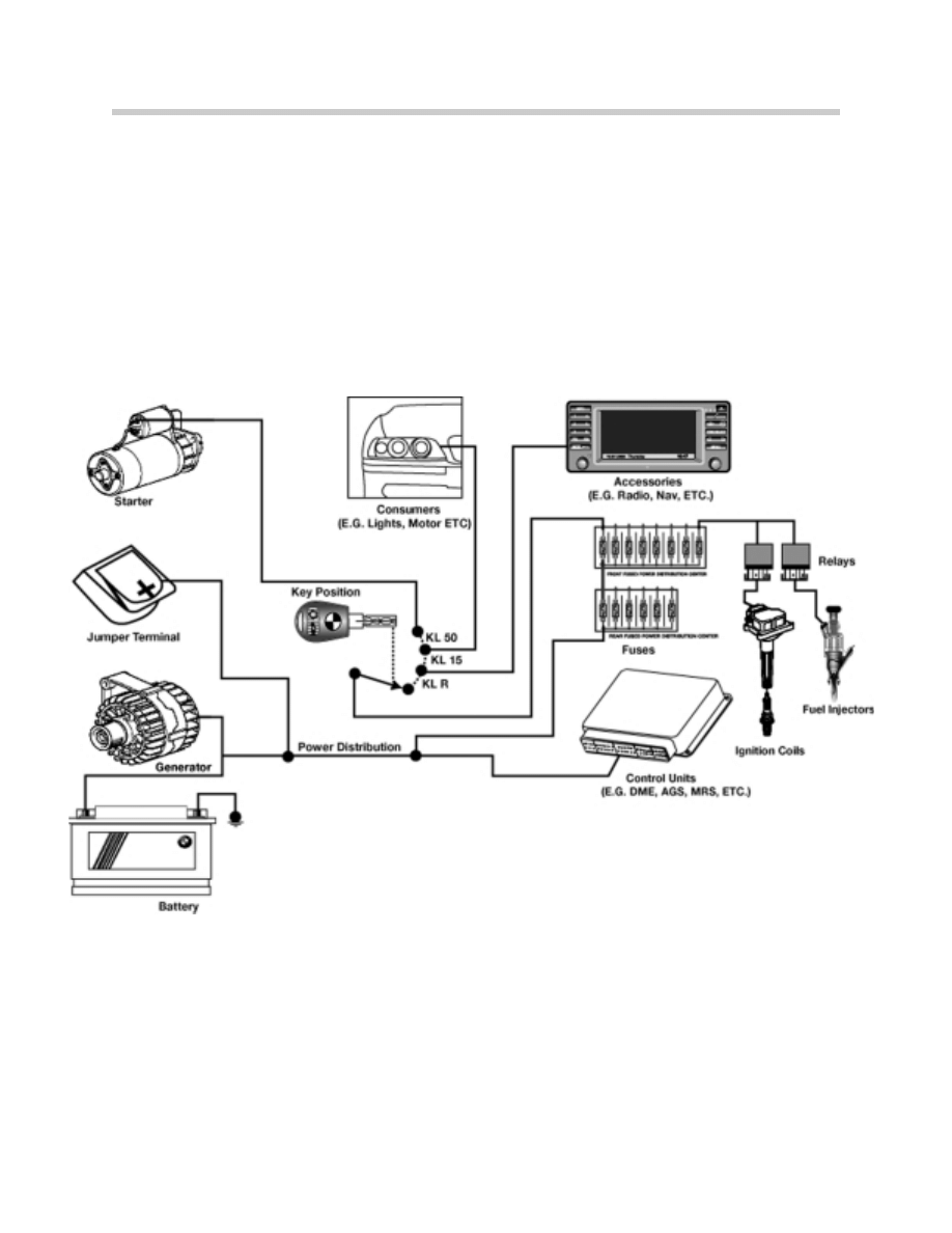
All things electrical start at the Battery
4
The Battery
The Battery
Purpose of the Automotive Battery
The battery is the primary EMF source in the automobile. In addition the battery performs
the following functions:
•
Provides voltage and current for the starter motor.
•
Provides voltage and current for the ignition during cranking.
•
Supplies all electrical power when the charging system is not operating.
•
Supplies the extra power necessary when the vehicle’s electrical load exceeds the
supply from the charging system.
•
Acts as a voltage stabilizer in the electrical system. The battery evens out voltage spikes
and prevents them from damaging other components in the electrical system.
•
Provides power to KL30, KL15 and KLR.
The battery does not store electrical energy. It stores chemical energy that is converted to
electrical energy as it discharges.
Battery Construction
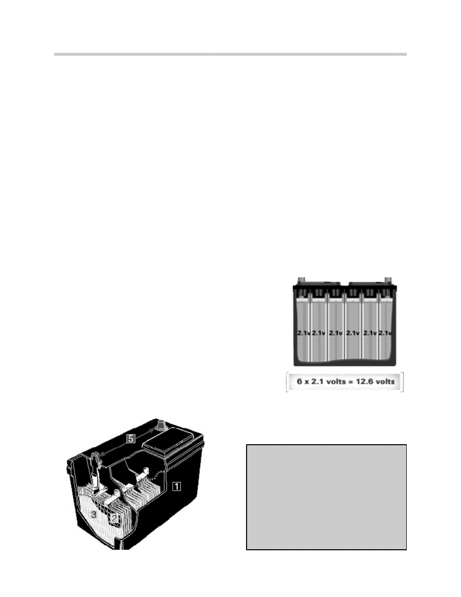
Modern automotive batteries are made of cases (usually
plastic) containing alternating plates of Lead and Lead
Dioxide (or Lead Oxide) separated by insulators. These
alternating plates are connected in series to produce a volt-
age of 12.6 volts, or about 2.1 volts for each set of Lead
and Lead Dioxide plates. The negative terminal is connect-
ed to a Lead Dioxide plate and the positive terminal to a
Lead plate.
The plates are covered with electrolyte which is a solution of 35% Sulfuric acid and 65%
Water.
1. Plastic container.
2. Positive and negative internal plates made
of lead.
3. Plate separators made of porous synthetic
material.
4. Electrolyte which is a dilute solution of
Sulfuric acid and water better known as
Battery Acid.
5. Lead terminals which are the connection
point between the battery and whatever it
powers.
5
The Battery
Battery Case
Most battery cases and their covers are made of polypropylene. The case is divided into six
sections or cells, shaped similar to an ice-cube tray.
The case is designed to:
•
Withstand hot and cold temperature extremes.
•
Resist damage caused by mechanical shock in automotive applications.
•
Resist acid absorption and chemical damage.
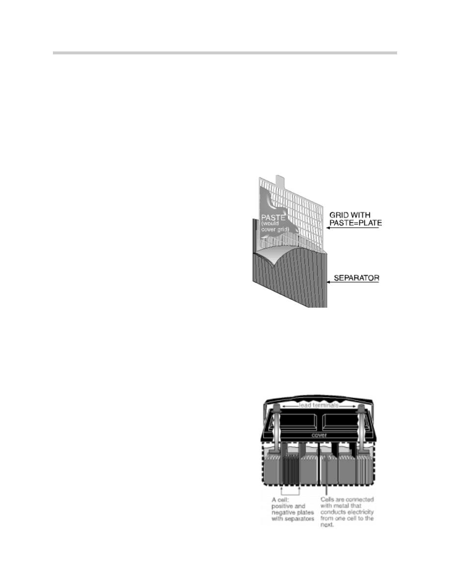
The Grids
The grids are the supporting framework for the
active material of the plates. They also con-
duct current to and from the active material
plates.
The Plates
Plates are grids covered with a paste mixture
of Lead Oxide and Sulfuric Acid and water. An
expander material made of powdered sulfates
is added to the paste to produce negative
plates.
A forming charge is applied to the positive plates converting the Lead Oxide to Lead
Dioxide, a highly porous material which allows the electrolyte to freely penetrate the plate.
A forming charge is also applied to the negative plates converting the Lead Oxide to
Sponge Lead. The Sponge Lead allows the electrolyte to penetrate freely allowing the
material beneath the plate surface to take part in the chemical reaction.
The Separators
Separators are thin sheets of electrically insu-
lating porous material used as spacers
between the plates to prevent short circuits
within the cells.
Fine pores in the separators allow ionic current
flow in the electrolyte between the positive and
negative plates.
5510108.gif
6
The Battery
Elements
In the most common method of construction, a stack of alternate positive and negative
plates are formed with separators between each positive and negative plate. The lugs of
the negative plates are welded together as are those of the positive plates. The plate strap
of each group of plates is used to connect them in series with the plate group of the next
cell, or with a battery terminal.
The assembly resulting from placing one positive plate group and one negative plate group
together, with separators is known as an element. There is one element per battery cell.
More or larger plates per cell will increase plate surface area and increase capacity of the
battery but will not affect the voltage output.
Electrolyte
The electrolyte is a mixture of Sulfuric Acid and Water. Electrolyte consists of 35% sulfuric
acid and 65% water.
The electrolyte is the carrier for the electric current to move between the positive and neg-
ative plates through the separators.
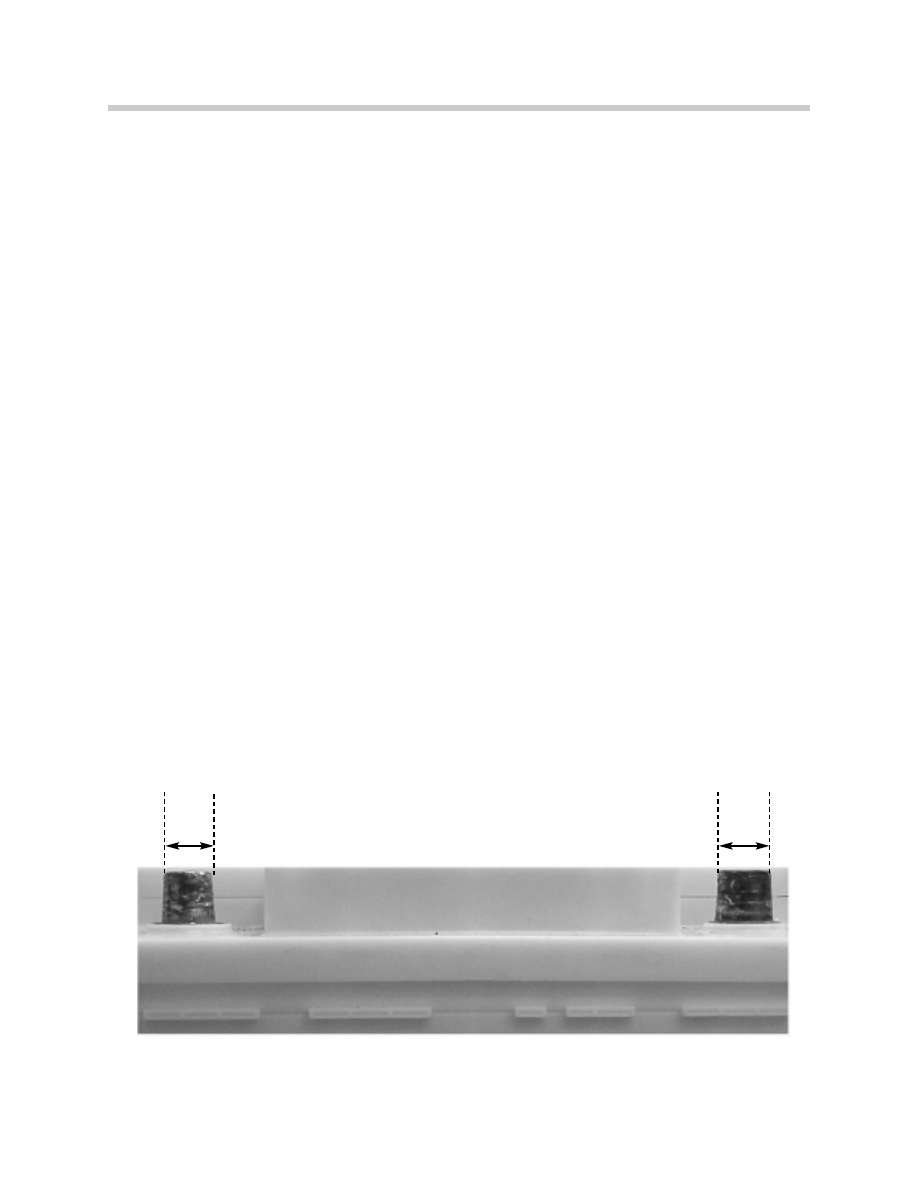
The Lead Terminals
BMW’s use a tapered top terminal. This design uses tapered terminal posts built to indus-
try standards so that all cable clamps will fit any battery with these posts.
The positive terminal is slightly larger than the negative to minimize the danger of installing
the battery in reverse. The positive terminal is 17.5mm in diameter at the top. The negative
terminal is 15.9mm at the top.
5510170.jpeg
15.9
mm
17.5
mm
Positive
+
Negative
-

7
The Battery
Battery Types
There are at least three types of the Lead-acid batteries that are currently used in the
Automotive Industry.
Lead-Acid Battery
The three major contributors to battery chemistry are lead, lead dioxide and sulfuric acid.
Pure lead is too soft to withstand the physical abuse of mobile applications, so a strenght-
ener is needed. About 6% antimony, a semi metallic element produced as a by-product to
copper and lead ore refining, is added to strengthen the lead.
The antimony added to the grids acts as a catalyst and makes the loss of hydrogen and
oxygen through outgassing worse. These batteries require frequent water replenishing.
Lead/Calcium Battery
Introduced in the 1970’s Lead/Calcium batteries have Calcium added to the positive and
negative grids to reduce the outgassing. These batteries were first referred to as “mainte-
nance free”. The Lead/Calcium batteries are not resistant to deep-cycling which occurs
when a battery is drained to a very low voltage before being recharged. Frequent deep-
cycling renders these batteries unable to sustain a charge. Lead/Calcium batteries need to
be charged at higher voltage settings or they will not be recharged to full capacity.
Hybrid Battery
Hybrid batteries use a positive grid strengthened with antimony and a negative grid with
calcium. The hybrid battery is more resistant to deep cycling than the lead/calcium, but still
not as good as the original Lead-acid battery. Water usage is greatly reduced in the hybrid
battery, although regular checking is advisable. Most cars supplied with hybrid batteries
have their voltage regulators set to 14.3 volts.
Hybrid batteries were first installed in the E30 convertible (SIB 61 12 91) during the 1991
Model Year.
8
The Battery
How The Battery Works
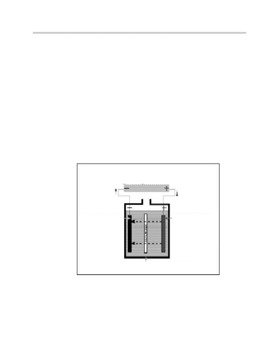
Discharging
Batteries don’t store electrical energy, they store chemical energy and convert it to electri-
cal energy during the discharging process.
Each cell of a battery contains positive and negative plates (grids). The positive plate is
made of lead dioxide, the negative plate of a spongy lead. The negative plate combines
with the sulfuric acid to create lead sulfate and one extra electron. The positive plate pro-
duces hydrogen ions and sulfuric acid ions (positive ions, atoms missing one electron).
The extra electrons from the negative plate are passed from the negative battery terminal
and through the electrical consumer, back to the positive battery terminal. Once back at
the battery, the free electrons combine with the positive ions at the positive battery termi-
nal producing lead sulfate and water.
It is important to remember that the system is closed. For every electron generated at the
negative terminal, there is an electron consumed at the positive terminal.
As the process continues, the active materials (lead and lead dioxide plates and the elec-
trolyte) become depleted and the reactions slow down until the battery is no longer capa-
ble of supplying electrons. At this point the battery is discharged.
The discharge process changes the ratio of sulfuric acid to water in the electrolyte, as more
water is produced in the discharge process. By measuring the volume of acid in the water,
the state of charge of the battery is discovered.
5510161.jpeg
Starter
Radio
Horn
Lights
Ignition
Positive
Lead peroxide
changing to
Lead Sulfate
Negative
Sponge lead changing
to Lead Sulfate.
Electrolyte
The sulfate of sulfuric acid unites with active material
on plates leaving water and acid solution. Hydrogen of
acid and oxygen of lead peroxide combine to form
water diluting solution.
Discharge Process
9
The Battery
Charging
Applying voltage to the battery from an external source such as the generator or battery
charger reverses the chemical action in the battery.
Reversing the chemical action in the battery, forces the free electrons at the negative ter-
minal of the battery back into the electrolyte raising the sulfuric acid percentage. This chem-
ical action removes the Lead sulfate that had formed on the negative plates leaving pure
active material.
The electrons that were forced into the electrolyte are able to react with the lead sulfate on
the positive terminal again raising the Sulfuric acid content and leaving pure active materi-
al on the positive plates.
This process enables the battery to be used over and over again.
5510160
Charging Process
Positive Plate
Lead sulfate changes
to lead peroxide.
Sulfate returns to
electrolyte
Negative Plate
Lead sulfate changes
to sponge lead.
Sulfate returns to
electrolyte
Very dilute electrolyte made stronger
by return of sulfate from plates.

10
The Battery
Common Battery Terms
•
Ah
-Amp Hour Capacity
This rating is derived from discharging a fully charged battery at a constant amp draw
for 20 hours @ 80
o
F, without the voltage of the battery falling below 10.5 volts. The
constant amp draw is multiplied by the 20 hours to come up with the Amp Hour Rating.
•
CCA -Cold Cranking Performance
Represents the amperage capacity a fully charged battery can deliver @ 0
o
F for 30
seconds before the voltage of the battery falls below 7.2 volts.
•
RC
-Reserve Capacity
Reserve capacity is expressed in minutes and relates to the amount of time a fully
charged battery can maintain a constant draw of 25 amps @ 80
o
F before the voltage
falls below 10.2 volts.
•
W
-Watts
The measurement of electrical power that the battery can deliver for a cold start. It is
calculated by multiplying the starter amperage draw @ 0
o
F times 10 volts.
•
V
-Volt
Unit of measure of potential difference (Electrical pressure).
•
A
-Amp
The current flow in a circuit. Value is proportional to the number of electrons flowing past
a point in one second.
•
W
-Ohm
The measurement of the resistance of a component or circuit to current flow.
Teile-Nr. (Part No.) 61021 6 902 796
12V 55AH 480A
EN 555 080 048
12V 90RC 425CCA
SAE Group No . 47
fur Ersatz (for replacement):
Teile - Nr. 61 21 6 902 796 Nass (wet)
95101104.eps

11
The Battery
•
Electrolyte
The mixture of sulfuric acid and water. 35% sulfuric acid, 65% water.
•
Specific Gravity
The measurement (by weight) of the volume of sulfuric acid in the electrolyte. A
specific gravity of 1.275 (the specific gravity of a fully charged battery) means that the
electrolyte is 1.275 times heavier than water. The specific gravity of water is 1.000.
•
Sulfate
Deposits formed on the plates of the battery as the electrolyte gives up its sulfuric acid.
Excessive deep cycling of a battery can cause a hardening of this deposit and make it
impossible to return sulfate to the electrolyte. A sulfated battery is one which has these
hardened deposits on the plates and cannot be recharged to full capacity.
•
OCV Open Circuit Voltage
The measurement of the voltage of a battery across the terminals.
Notes
Original BMW
Teile-Nr.(Part No.) 61 21 8 381 762
12V 90Ah 720A EN 590 051 072
12 V 175C 850CA SAE
fur Ersatz (for replacement).
Teile-Nr.61 21 8 381 762 neB (wet)
ManUfaxtured for
DETA-DOUGLAS
BATTERIES, INC.
by:
DOULAS BATTEY
Winston-Salem, NC
551072-1.eps
12
The Battery
Battery Testing
There are four steps to follow in testing an automotive battery:
•
Inspection
•
Removal of Surface Charge
•
State-of-Charge Test
•
Load Test
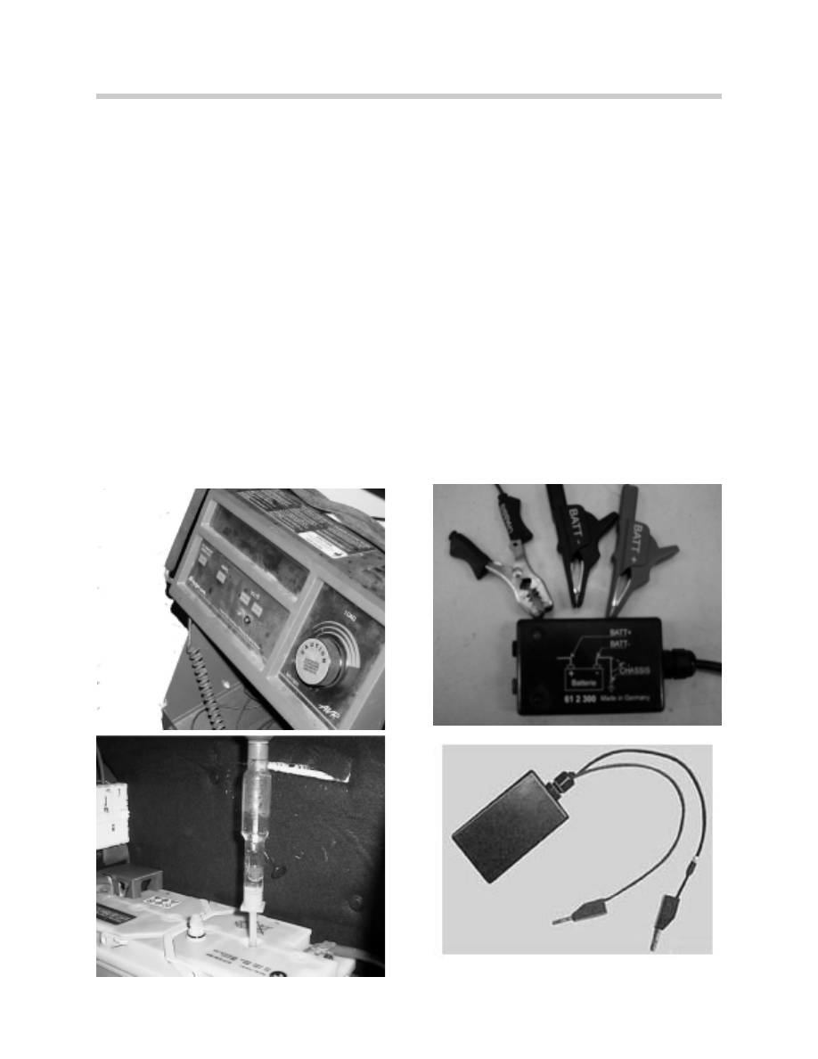
Tools Needed
To test a battery following tools are needed:
•
DVOM Digital Volt Ohm Meter
•
Battery Load Tester (i.e. Snap On VAT 60)
•
DISplus or MoDic
•
Battery Draw Test Special Tool PN 61 2 300
•
Closed Circuit Measurement Adapter PN 90 88 6 612 310
•
Temperature Compensating Hydrometer
5510112.jpeg
5510173.jpeg
6510199.jpeg
5510174.jpeg
13
The Battery
Inspection
Visual inspection is important for the detection of obvious problems:
•
Loose Generator Belt
•
Low Electrolyte Level
•
Corroded Cable or Terminal Clamps
•
Loose Hold-Down Camps or Cable
Terminals
•
Damaged Battery Case
Removal of Surface Charge
If the battery has just been recharged, or the car has been driven, eliminate any surface
charge by one of the following methods:
•
Allow the battery to sit for 2-3 hours.
•
Turn the headlights on high beam for 5 minutes and wait 5 minutes after turning off.
•
With battery load tester, apply a load of 1/2 the battery’s CCA for 15 seconds, then wait
5 minutes.
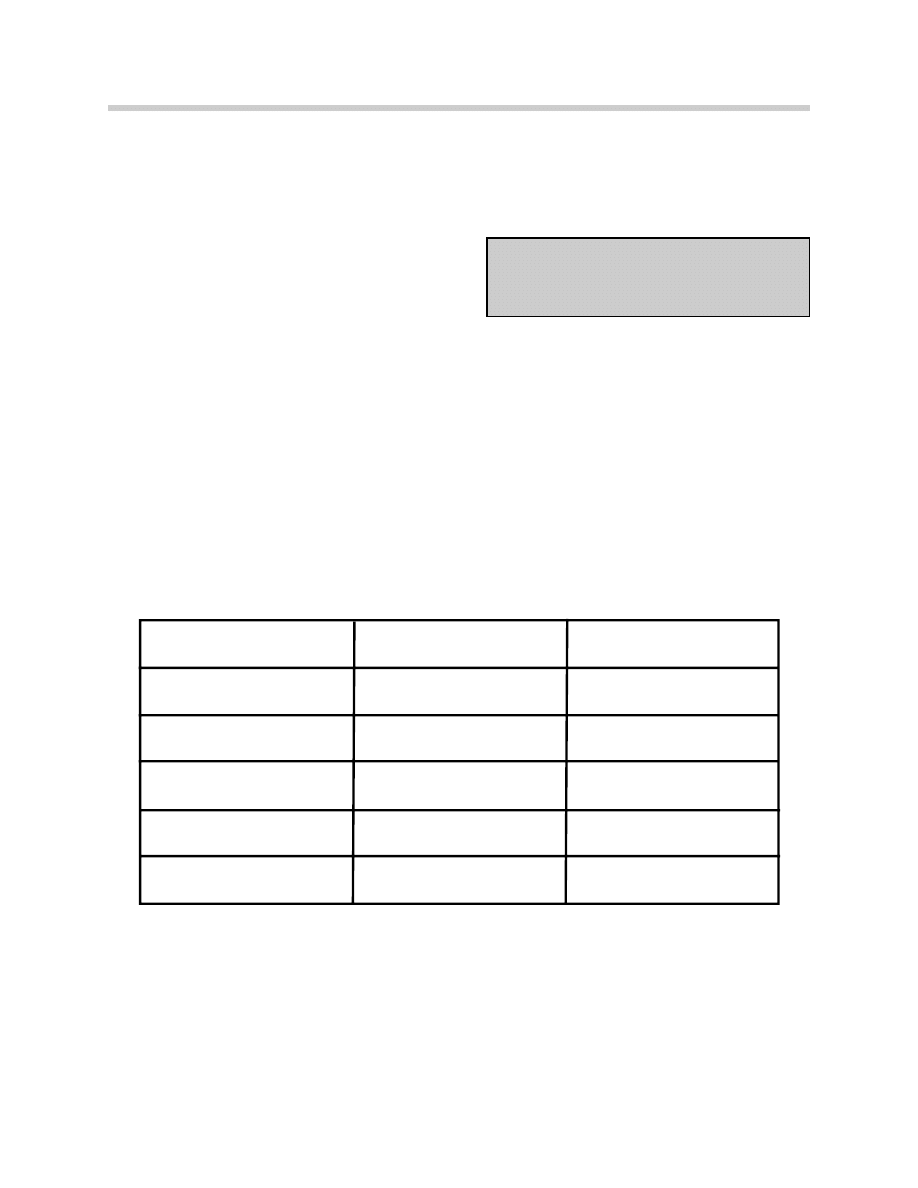
State-of-Charge Test
Use the table to determine the battery’s State-of-Charge.
Pay special attention if the DVOM measurement of OCV is equal to:
•
0 volts -Indicate an open cell.
•
10.45 - 10.65 volts -Indicates a shorted cell.
Note:
The proper electrolyte level is just covering the
plates, not all the way to the top of the battery
inspection holes.
Open Circuit Battery Voltage
Approximate State Of Charge
Average Cell SG
12.65 +
100%
1.265 +
12.45
12.24
12.06
11.89
75%
50%
25%
0%
1.225
1.190
1.155
1.120
5510173.eps

14
The Battery
For non-sealed batteries, check both specific gravity (SG) in each cell with a temperature
compensated hydrometer and battery OCV, without the engine running.
For sealed batteries, measuring the battery’s OCV (without the engine running) with an
accurate DVOM is the only way to determine the state-of-charge.
Batteries with a built-in hydrometer measure the state-of-charge in one cell only. If the indi-
cator is clear or light yellow, the battery has a low electrolyte level and should be refilled
before proceeding or replaced.
A state-of-charge reading BELOW 75% using SG, voltage measurement or dark indicator
in batteries with built-in hydrometers, indicates the battery must be recharged before pro-
ceeding.
Replace the battery if one or more the the following conditions are met:
•
More than 0.050 difference in the specific gravity readings between the highest and
lowest cell (There is a weak or dead cell).
•
The battery will not recharge to 75% or greater state-of-charge or the built in
hydrometer does not indicate good (green indicates 65% or better).
•
DVOM reading indicates 0 volts (Open cell).
•
DVOM reading indicates 10.45 - 10.65 volts (Shorted cell).
Load Test
A battery which has a state-of-charge of 75% or greater or has a “good” built-in
hydrometer indication may be load tested.
With a battery load tester properly installed, load the battery for 15 seconds to one of the
following:
•
One-half (1/2) the CCA (Cold Cranking Amps).
•
Three (3) times the AH Rating (Amp Hour Rating).
The voltage on a good battery will NOT drop below
9.7 volts during the battery load test. After the load is
removed, wait 5 minutes, the battery should bounce
back to 50% or greater state-of-charge. If a battery
drops below 9.7 volts during the load test, does not
bounce back or fails to start the engine, the battery
should be replaced. Batteries which pass this test
should be recharged to restore peak performance.
Load Test Conditions
Tests assume electrolyte temperature of
80
0
F, 26.7
0
C.
If the electrolyte temperature is above
80
o
F add .1 volt for every 10 degrees up
to 100
0
.
If the temperature is below 80
0
F sub-
tract .1volt for every 10 degrees to 40
o.

15
The Battery
Battery Maintainence
Electrolyte Level
If battery electrolyte level is allowed to drop substantially, the gas volume inside the battery
grows proportionately resulting in an increased amount of flammable gas mixture. Any
external or internal spark may result in an oxyhydrogen explosion. Additionally the plates
are no longer covered by the electrolyte and may corrode.
As described in SIB 61 01 90, battery electrolyte level should be checked on every
Inspection I and Inspection II.
Use only distilled water to top up the battery !
Tap water and electrolyte must never be used
to refill or top off an automotive battery.
Battery Cable Connections
The top of the battery should be clean.
Check for and correct corrosion on the top of
the battery and the cable connections.
Battery Charging
The purpose of charging a battery is to put back the energy that has been removed.
A battery that is not properly charged will deliver sub-standard performance and display a
shorter life span.
A battery should be charged only after performing a visual inspection on the battery case
and the electrolyte levels. Never attempt to charge a battery with a damaged case or low
electrolyte levels.
A state-of-charge test should be performed before attempting to charge a battery.
Always connect the positive lead of the battery charger to the positive terminal of the bat-
tery and the negative lead of the battery charger to the negative terminal of the battery.
Unplug the the charger or turn it off BEFORE disconnecting the leads at the battery.
Workshop Hint
Electrolyte levels may drop at a higher rate in
the winter months, due to higher loads and
increased utilization of electrical systems
( SIB 61 01 90).
Workshop Hint
Many battery problems are caused by loose or
corroded connections. Insure that cables are
free from corrosion and tight before continuing
diagnosis.

16
The Battery
Batteries that are fully discharged should be charged according to the following table.
The best charging method is to SLOWLY recharge the battery using the BMW approved
battery charger. .
A slow charging rate allows more time for the electrolyte to penetrate the plates.
Sulfated Batteries
Continuous discharging of the battery or low electrolyte levels cause crystals to form on the
plates. These crystals of lead sulphate occur when a battery is discharged. The deeper the
discharge the more serious the sulphation. The sulphur molecules that form the sulphate
are then absent from the electrolyte, causing the electrolyte to become inefficient.
A battery relies on clean plates and strong electrolyte to both receive charging current and
offer strong current discharge. A sulphated battery can do neither. Proper recharging of the
battery will remove some but not all of the sulphate. Eventually the battery plates are coat-
ed with enough sulphate that it is impossible to achieve an efficient recharge.
Testing A Battery for Sulphation
A battery which fails the load test should be tested for sulphation. To test a battery for sul-
phation, place it on a battery charger for three minutes with the charger set on 40 amps.
After three minutes check the OCV, if the reading is greater than 15.0 volts the battery is
sulphated. Batteries which indicate a sulphated condition should be recharged slowly and
retested before being discarded.
Reserve Capacity Rating (RC)
Slow Charge
Fast Charge
80 minutes or less
15 hours @ 3 amps
2.5 hours @ 20 amps
80 to 125 minutes
125 to 170 minuites
170 to 250 minutes
Above 250 minuites
21 hours @ 4 amps
22 hours @ amps
23.hours @ 6 amps
24 hours @ 10 amps
3.75 hours @ 20 amps
5 hour @ 20 amps
7.5 hours @ 10 amps
6 hours @ 40 amps
5510174.eps

17
The Battery
Battery Freezing
A fully charged battery can be stored at sub-freezing temperatures with no damage. The
battery is protected from freezing to a temperature of -75
o
F. A fully discharged battery
however will freeze at +27
o
F.
Avoid freezing by keeping the battery fully charged.
Carefully inspect a battery which has frozen for a cracked case.
Battery Maintenance (Center Vehicles)
The battery charge is monitored while the vehicle is at the VPC and before it leaves on the
transport. When the vehicle is having the QC I performed at the center the check list
requires that the battery voltage be checked and maintained to 12.65V minimum.
In order to facilitate tracking vehicles in inventory, BMW has in place a Battery Maintenance
Program. The program uses :
•
Battery Log Forms
•
Battery Log Binder
•
Colored windshield stickers (red, green, yellow and white)
The Battery Maintenance Program has three possibilities:
•
Vehicle in storage, battery disconnect switch removed
•
Vehicle in showroom or display
•
Vehicle in storage, Battery disconnect switch left in the vehicle
Vehicle In Storage, Battery Disconnect Switch Removed
A four week charging cycle has been established for these cases. All vehicles arrive with a
color coded sticker on the windshield. The color corresponds to the week that the battery
must be charged. Also the vehicle will be provided with a Battery Log Form.
The “A” portion (Vehicle Receipt) of the Log Form must be completed during the QC I
Display check and then has to be filed in the Battery Charge Log Book under the
applicable color coded section. All the vehicles in that color section will have to be charged
that week.
Vehicle In Showroom or Display
Because of the high consumer demand on vehicles that are being displayed and not
driven, a four week charging cycle is not enough. For vehicles in the showroom the
battery has to be charged as frequently as necessary to ensure that the battery never drops
below 12.5V. Use the ”C” portion of the log form (Display Vehicle - Monitored Daily) to keep
track of the charging and checking of the battery.
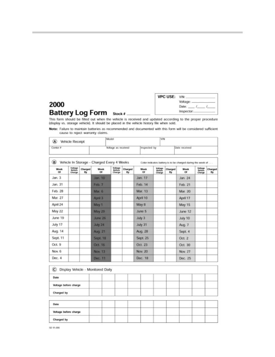
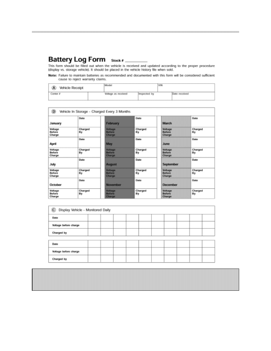
Vehicle In Storage, Battery Disconnect Switch Left In The Vehicle.
Since the battery disconnect switch is left installed and in the “OFF” position the 3 month
charge cycle can be used. Use the “D” section of the Battery Log Form to document when
the battery is charged.
Upon the sale of the vehicle, the Battery Log Form should be removed from the binder and
placed in the vehicle file for future reference.
18
The Battery
19
The Battery
Note:
If the battery voltage drops below 11.6 v for three days or more the battery must be
replaced before delivery to the customer
20
The Battery
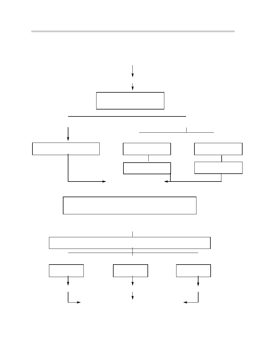
Battery Maintenance Flowchart
Vehicle Received at BMW center
Quality Certification I
ShowroomStorage
Condition 1
Condition 2
Quality Certification I
(Delivery Check)
If Battery Voltage has been below 11.65V for
3 or more days, the battery must be replaced.
Condition
Condition
Condition
O.K.
Recharge
Replace Battery
Vehicle Prepared for Customer Delivery
Move Battery Log Form to vehicle history file.
Check battery Voltage
Charge if below 12.65V
Complete section “A” of log form.
Follow section “C”(Log Form)
Maintain Voltage above 12.65V.
Battery switch removed
or “ON”.
Battery switch installed
Follow 4-week cycle
(section “B” Log form).
Follow 3-month cycle
(section “D” Log Form).
•
Remove Battery disconnect switch
•
Tighten battery ground cable nut to 15Nm (after switch removal)
•
Check charge of battery. Recharge if below 12.65V.
Load test battery at 90% of DIN cranking current or 4x DIN rating for maximum of
15 seconds and observe Voltage reading.
Voltage
above 10.5V.
Voltage
9.6 - 10.5V.
Voltage
below 9.6V

21
The Battery
Battery Replacement
Batteries determined to be defective through testing procedures should be replaced using
the following guidelines.
•
Reconfirm battery is actually defective and it does not need charging.
•
Insure that ignition switch is in “Off” position and engine is not running.
•
Disconnect negative battery terminal first.
•
Place negative battery cable in a position so that it can not come in contact with
battery during removal process.
•
Reinstall battery hold down clamp.
•
Install positive cable first.
•
Recheck output of vehicle generator and balance of electrical system for other
problems.
•
Provide clear and concise description of the defect including cell readings, load test
results and any other pertinent information which led to the battery replacement.
•
Tag battery with VIN and repair order number.
Battery Failures
An analysis of batteries replaced under warranty shows that many claims could have been
avoided had the batteries been maintained in a full state of charge.
Batteries must be maintained at all times when vehicles are at a retailer whether they are
new cars, used cars, in storage (back lot), on display, or customer cars in for maintenance
or repairs.
Batteries replaced due to lack of maintenance will not be covered by warranty.
Most Common Causes of Premature Battery Failures
•
Failure to maintain proper state of charge.
•
Loss of electrolyte due to overcharging or excessive heat.
•
Deep discharging (Leaving lights on or other parasitic draws).
•
Undercharging of battery.
•
Vibration (Loose battery hold down clamp).
•
Using tap water (instead of distilled water).
•
Corrosion.
•
Freezing.

22
The Battery
Workshop Hints
Safety Tips
•
Proper Clothing:
-Always wear a face shield or safety goggles.
-Plastic gloves can prevent acid burns to hands.
•
Neutralizing Electrolyte:
Any leakage or spillage of battery electrolyte should be neutralized as soon as possible
to prevent damage to paint, body or trunk linings. Depending on the amount of spillage
dilute some baking soda in water and apply to areas of the car that have been exposed
to the battery electrolyte. The neutralizing action will create some foaming in the area
where the chemical action takes place. Flush with ample amounts of water once the
chemical reaction has subsided.
General Battery Hints
•
Add only distilled water NEVER TOP OFF WITH ACID.
• Keep electrolyte level above plate separators.
•
Keep battery top clean and dry.
•
Keep open flame and metal objects away from battery top and terminals.
•
Keep vent caps tightly in place (if applicable).
•
Use proper charging equipment.
Notes

23
The Battery
Workshop Exercise
1.
Vehicle Model:
Record OCV and Battery Ratings:
Perform Battery Test:
Step A:
Step B:
Step C:
Step D:
What was the State-of-Charge prior to testing:
At what amperage was this battery tested:
What was the voltage after Load Testing:
Did the voltage change after the waiting period:
2.
Vehicle Model:
Record OCV and Battery Ratings:
Perform SG test with hydrometer:
Record Results:
Cell1:
Cell2:
Cell3:
Cell4:
Cell5:
Cell6:
What is the State-of-Charge of this battery:
Are the SG reading within specified limits:

3.
Vehicle Model:
Record OCV and Battery Rating:
Perform Battery Sulphation Test:
Is this battery sulphated:
A voltage reading during this test of 15V indicates:
What should be done with a battery which fails this test:
What would be the optimum charge rate and time to charge this battery in an attempt
to recover the battery:
Why is a slow charging time preferred:
At what temperature would this battery freeze:
Battery Notes:
24
The Battery
25
The Battery
Special Battery Systems
Special battery systems are broken into two groups:
•
Vibration Compensating Battery Systems
•
Dual Battery Systems
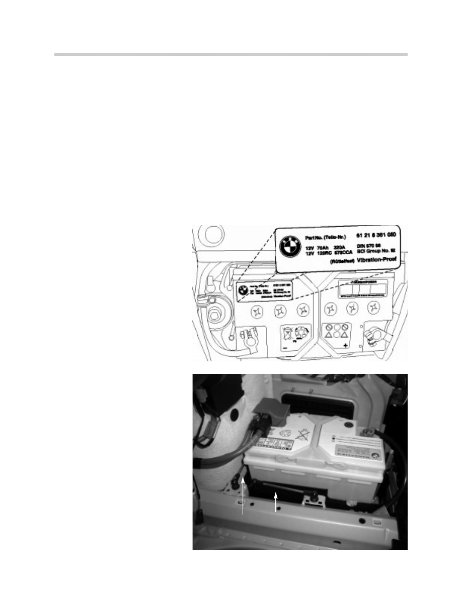
Vibration Compensating Battery Systems
Vibration Compensating Battery Systems act as vibration absorbers, smoothing out road
vibrations in the E36 and E46 convertibles.
E36 :
The E36 convertible is not only
an energy source. The battery is
designed as a vibration dampen-
er. Due to this additional function
the battery also has a special tray
with an integrated vibration
absorber.
Note: E36 convertible batteries
are labeled “Vibration Proof”.
Replacement batteries must be
of the same type.
E46:
The E46 convertible uses the
same battery as the E46 sedan,
coupe and touring. The battery
box is specially designed to float
on the vertical axis through three
articulated rods.
This allows the battery to act as
an inertia mass and dampen var-
ious vibrations while the vehicle is
driven.
5510131.jpeg
5510133.jpeg
Dampening Rods

26
The Battery
Dual Battery Systems
E31 (850i):
The dual battery system on the 850i was introduced to handle the higher level of electron-
ic technology with increased functions and safety features that were added to the vehicle,
as well as the added diagnostic information.
Design considerations were made to minimize electrical loads during Key Off and periods
of driving with low engine speeds while certain timed operations (e.g. Glove compartment
light, courtesy lights and seat heating) were active.
Special testing and charging procedures exist for the dual battery system on the 850i, refer
to SIB 61 10 90 and SIB 61 06 91 for specific information.
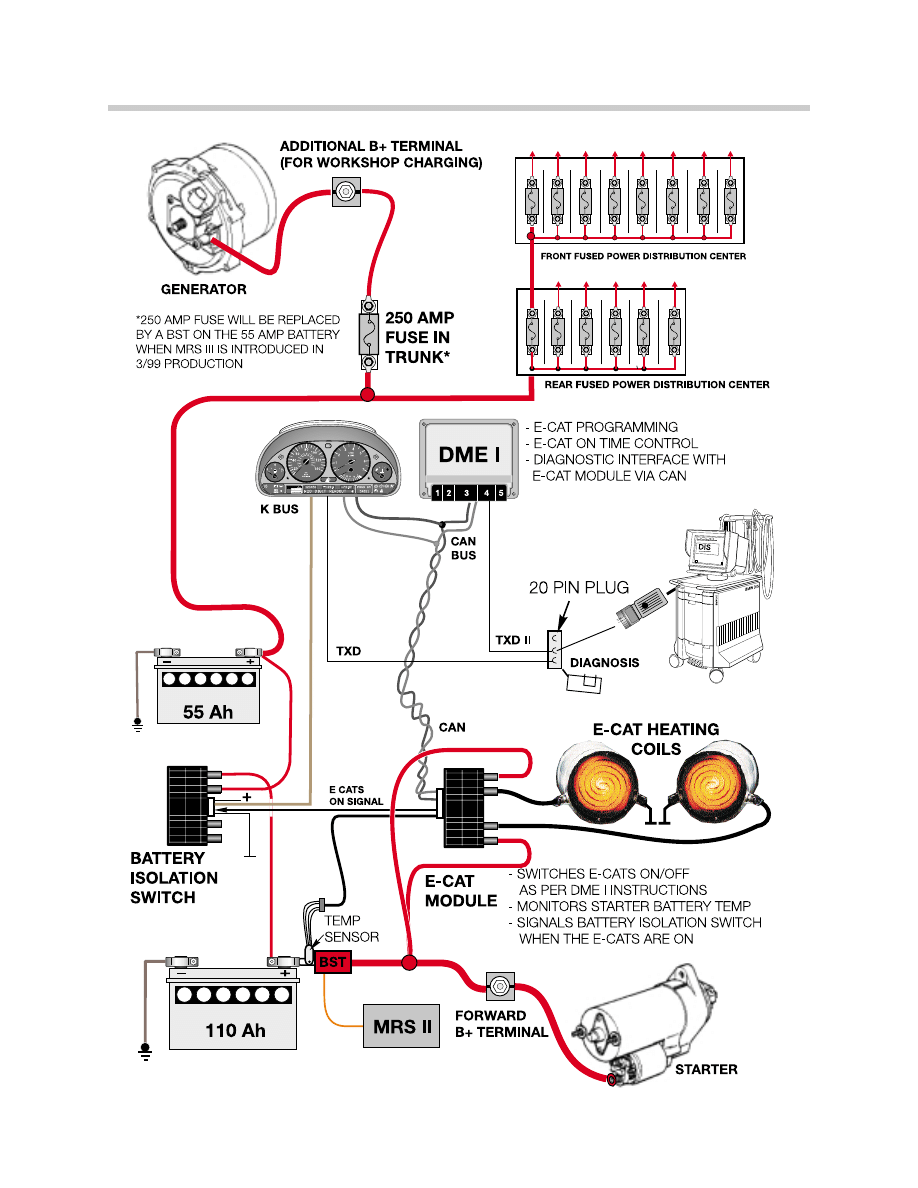
E38 750iL:
The dual battery system on the 750iL is necessary due to the addition of the E-CATs.
If a single battery system was used, the E-CATs would be provided power from the single
battery just after cold engine start-up when the battery is at its lowest capacity. This would
increase engine loads due to charging of the single battery and cause an increase in injec-
tor “On” time during the cold engine warm-up period, which result in unnecessary tail pipe
emissions.
Providing separate battery systems for the starting circuit and the vehicle circuits also min-
imizes the possibility of a discharged starter battery ensuring reliable engine starting.
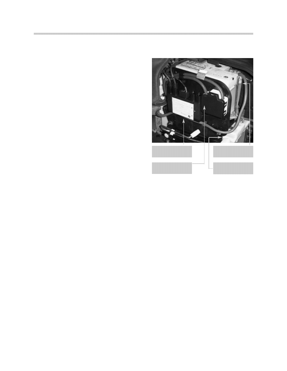
Components of E38 Dual Battery System
•
Starter Battery: Located in the right rear trunk wheel, the starter battery is connected
to the starter motor and to the heating coils of the E-CATs (via the E-CAT module).
•
Vehicle Circuit Battery: Located above the starter battery on a swing out mount, the
vehicle circuit battery provides operating power for the balance of the vehicles electrical
requirements and is directly connected to the vehicle generator.
•
Battery Isolation Switch: Located on the swing out mount of the vehicle circuit battery
the battery isolation switch opens and closes the circuit between both batteries based
on monitored conditions.
Note:
The battery isolation switch is NOT used to boost a discharged starter battery
with the voltage of the vehicle circuit battery to start the engine.
The battery isolation switch can only withstand a maximum current flow of 60
amps.
27
The Battery
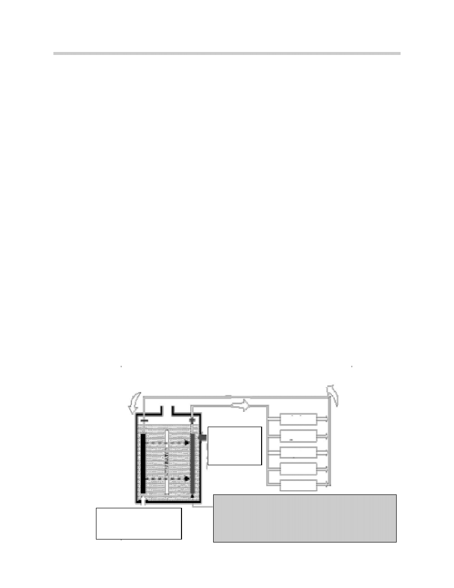
Battery Isolation Switch
The Battery Isolation Switch provides the vehi-
cle with separate battery systems for the vehi-
cle circuits and the starting circuit.
When the isolation switch is open, the vehicle
circuit battery is the only power source con-
nected to the power distribution center.
When the isolation switch is closed the starter
battery is charged and the vehicle circuit bat-
tery is boosted by the starter battery.
Modes of the isolation switch:
•
Starting Mode
-Normal Starting
-Safety Starting
•
Driving Mode
•
Charging Mode
•
Sleep Mode
Starting Mode
When the isolation switch recognizes KL15 via the K Bus, it determines the voltage of the
vehicle circuit battery.
•
If the vehicle circuit battery IS sufficiently charged, it proceeds with Normal Starting.
•
If the vehicle circuit battery IS NOT sufficiently charged, it proceeds with Safety
Starting.
Normal Starting
•
The isolation switch is open.
•
Within 0.5 seconds of engine start-up the E-CAT module energizes the E-CAT heating
coils (program dependent) and simultaneously signals the isolation switch that the E-
CATs are “On” via signal “KATON” (low signal).
•
Upon completion of the heating period, the E-CAT module signals the isolation switch
that the E-CATs are off (High Signal).
•
Under normal conditions, the isolation switch is not closed before the heating
procedure is finished.
5510137.jpeg
Battery isolation
switch
Starter/E CAT
battery
Vehicle circuit
battery
250 amp gener-
ator circuit fuse

28
The Battery
Safety Starting
•
In response to a discharged condition of the vehicle circuit battery, the isolation
switch closes to momentarily boost the vehicle circuit battery and supply all systems
with starter battery voltage via the power distribution center.
This operation lasts for a maximum of 30 seconds or until confirmation of engine start
up is received. (TD signal on the K Bus)
•
Receiving the TD signals causes the isolation switch to immediately open for the dura-
tion of the E-CAT heating cycle.
•
If the engine is not started within the 30 seconds, the isolation switch opens and
remains open until KL 15 is recognized on the next start-up cycle.
Driving Mode
The vehicle circuit battery is permanently connected in parallel to the generator and is
charged when the engine is running. When the isolation switch is closed, the generator
simultaneously charges the starter battery.
As the vehicle is driven the isolation switch cycles between open and closed based on:
•
Voltage values of both batteries.
•
Current transfer between both batteries as monitored by the isolation switch.
•
Internal temperature of isolation switch.
Conditions Causing Switch To Open While Driving
•
Sufficiently charged starter battery.
•
Current flow through switch exceeding 0.5 amps.
The starter battery will supplement vehicle electrical needs during periods of high
demand (e.g continuous wiper operation combined with lights and blower).
•
The internal temperature of the isolation switch exceeds programmed maximum value.
Conditions Causing Switch To Close While Driving
•
Monitored voltage of vehicle circuit battery exceeds that of starter battery by 0.7 volts.
•
The voltage of the vehicle circuit battery drops below 9 volts three times within one
minute.
29
The Battery
30
The Battery
Charging Mode (in the workshop)
The isolation switch monitors starter battery voltage during key off conditions and contin-
ues monitoring after the vehicle and the isolation switch have entered sleep mode.
•
If starter battery voltage exceeds 13.8 volts during charging in the workshop, the
isolation switch comes out of sleep mode and closes.
This causes the starter battery voltage to bleed off to the vehicle circuit battery,
charging the circuit battery and protecting the starter battery from overcharging.
The isolation switch remains closed until the next key on cycle.
Sleep Mode
The isolation switch goes into sleep mode as soon as the engine is switched off. The cur-
rent draw of the isolation switch drops below 1mA. The isolation switch comes out of sleep
mode if:
•
KL15 is recognized
•
Starter battery voltage exceeds 13.8 volts (charging mode)
Failure of KATON signal
If the KATON signal is not received due to:
•
Open or short to B
+
- isolation switch closes for 4 seconds after start-up, TD received.
•
Short to B
-
- isolation switch opens 60 seconds after receiving TD
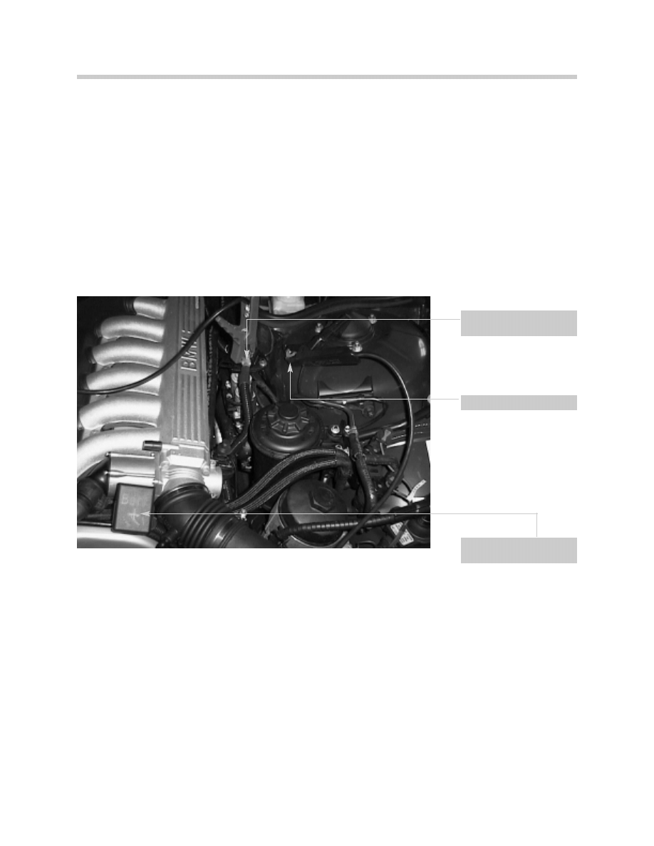
Vehicle circuit battery
B
+
terminal
Starter Battery B
+
Terminal
Vehicle B
-
Connection

31
The Battery
Workshop Exercise
1.
Vehicle Model:
Access battery isolation switch through Diagnosis:
Though Component Activation, check status of disconnecting switch:
Trigger closing of disconnecting switch:
Observe and record voltage change is system and starter battery and note change
when status of switch is changed:
What is the nominal resistance of the semiconductor switch with disconnect switch
closed:
Open:
What is the temperature of the power circuit-breaker in the disconnect switch:
How many Test Modules are available for the disconnect switch:
Start engine and observe status of disconnect switch:

32
The Battery
Closed Circuit Current Draw Testing
Increased closed-circuit currents may occur permanently or intermittently and cause the
battery to discharge prematurely. The increase in closed circuit current may be caused by
a faulty control unit or by the installation of a non-approved accessory.
In a situation where a vehicle has broken down due to a discharged battery, for diagnostic
purposes it is important not to disconnect the battery. The control unit may reset if the bat-
tery is disconnected. Following a reset, a faulty control unit may start functioning correctly
again, making accurate diagnosis impossible.
Tools Needed
•
Closed Circuit Current Measurement Adapter
•
MoDic Adapter
•
DISplus, MoDic or DVOM
To correctly measure closed-circuit current, measurement adapter 61 2 300 (P/N 90 88 6
612 300) should be used. This tool provides a bridge to ground, before the negative bat-
tery terminal is disconnected, and this prevents the control units from being reset.
The additional use of MoDiC adapter 61 2 310 (P/N 90 88 6 612 310) provides a method
for current measurements over an extended period of time.
The measuring device needed depends on the situation.
The DISplus may be used in situations of suspected high current draw.
The 1000 amp probe measures AC and DC current from 0 to 1000 amps. It is a self cali-
brating inductive pick-up. (Use this pick-up with current draws over 10 amps)
The DISplus, through MFK 1 is capable of measuring up to 2 amps.
The MoDic is particularly suitable for extended measurements and provides a graphical
readout of recorded measurements over time. It is recommended for the situations where
the use of a multimeter provided insufficient information for problem diagnosis.
The DVOM may be used for measurements up to 10 amps either with the measurement
adapter or alone.
Note:
It is extremely important that the battery is NOT disconnected during the installation of test
equipment. Disconnection of battery may cause faulty component to function normal.
33
The Battery
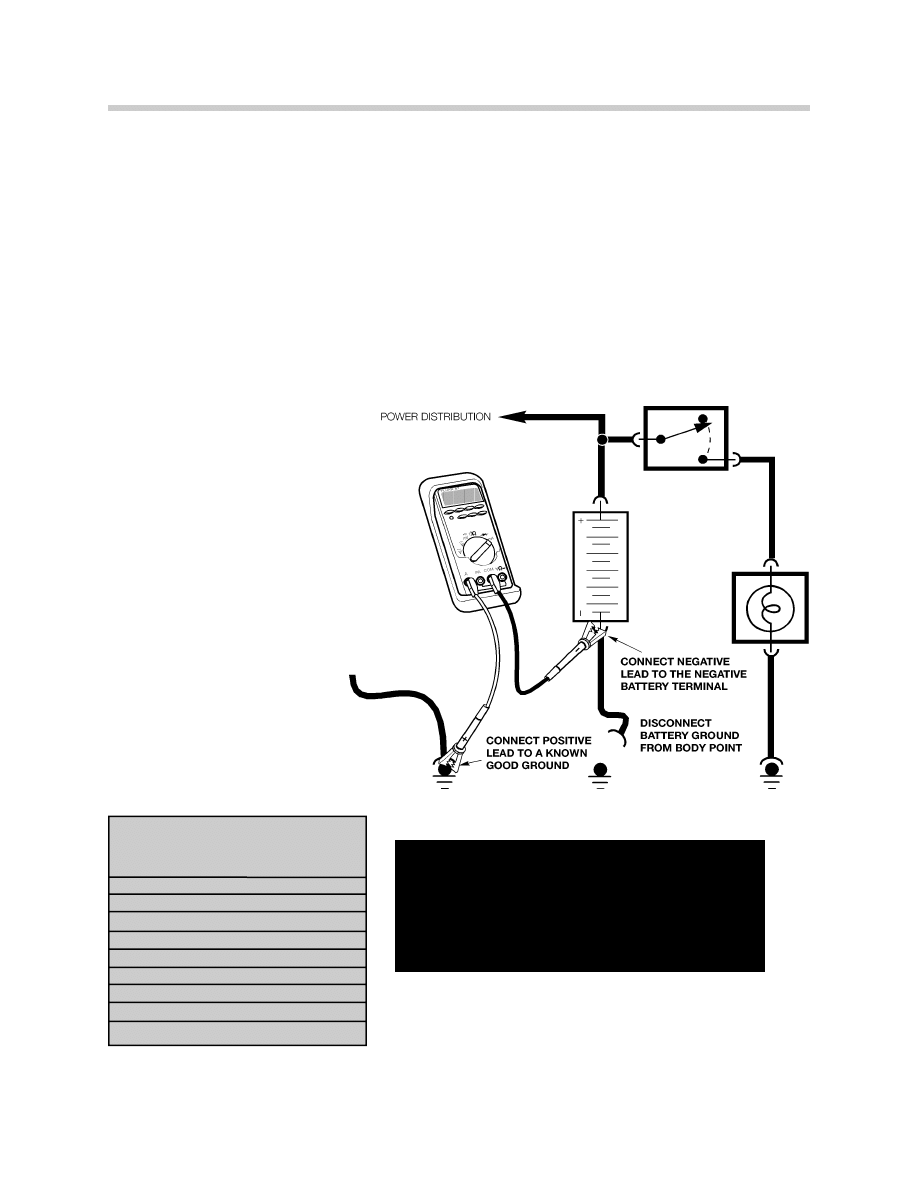
Performing Closed Current Draw Test
•
Select proper measuring device (DISplus, MoDic or DVOM)
-Remember amperage draw in excess of 10A will damage DVOM.
-Use inductive amp probe of DISplus when amperage draw is high.
-When using DISplus inductive probe, clamp on negative battery cable with
-arrow pointing away from battery. Switch off all consumers.
-(It is not necessary to disconnect B
-
from body when using inductive probe)
•
Connect (-) test lead to negative battery terminal and (+) test lead to a known good
ground.
•
Ensure all systems are OFF !
•
Be sure DVOM is on and set in
proper mode.
•
Disconnect battery ground lead
from body.
•
Observe meter reading, wait for
vehicle to enter sleep mode.
•
Identify faulty circuit by disconnecting
fuses, relays, control
modules or connectors,
observing meter readings.
•
Defective circuit is found when
current is below maximum closed
current for vehicle being tested.
Maximum closed current by vehicle
E31
50mA
E32
50mA
E34
40mA
E36
30mA
E38
50mA
E39
40mA
E46
40mA
E52
50mA
E53
40mA
Z3
30mA
Note:
Refer to SIB 61 08 00 for complete instructions
to perform closed circuit current measurement
using measurement adapter and MoDIc
adapter.

34
The Battery
Workshop Exercise
1.
Vehicle Model:
Perform Closed Current Draw Testing:
Record current at:
Initial:
5 Minutes:
10 Minutes:
16 Minutes:
2.
Vehicle Model:
Customer Complaint: Battery goes dead overnight.
Observations/Symptoms/Faults stored:
Test steps/modules recommended by diagnostic program:
Test steps/modules performed:
Results:
Repair Recommendation:
Notes:

35
The Battery
Review Questions
1. What functions does the battery provide?
2. What is electrolyte?
3. A battery rating of 425CCA indicates what?
4. What four steps are followed during a battery test?
5. An OCV of 12.65 indicates?
6. What would be the expected OCV for a battery with a shorted cell?
7. A battery should be replaced if the SG readings vary by more than per cell.
8. What is the state-of-charge in a battery with a SG of 1.190?
9. A battery should be load tested to the CCA rating. True False
10. During a load test, the electrolyte temperature is 100
o
F, and the voltage drops to
9.8 volts. Is this acceptable?
11. How can a battery be tested for sulphation?
12. What section of the Battery Log Form must be filed out during QC I?
13. What is the most common cause of battery failure?
14. When is it OK to add acid to a battery?
15. Does the E46 convertible use a “Vibration Proof “ battery similar to the E36
convertible?
16. Why was a dual battery system added to the E38 750iL?

36
The Battery
17. What is the maximum current flow the battery isolation switch can withstand?
18.When does the battery isolation switch allow the vehicle circuit battery to boost the
starter battery?
19. What three conditions may cause the battery isolation switch to open while driving?
20. When does the battery isolation switch come out of the sleep mode?
21. How does current flow through the separators in a battery?
22.As a battery is discharged, what happens to the electrolyte?
24. What is the freezing point of a fully charged battery?
25. Why should the battery NOT be disconnected while preparing for a closed current
measurement test?
26. During a closed circuit measurement test using a DVOM, the meter reading shows
out-of-range. How is the test best completed?
27. When charging a fully discharged battery with a RC rating of 90, the battery should
be charged @ .
28.The starter battery is located above the vehicle circuit battery on a swing out mount
True False .
29. Which type of battery is more resistant to deep cycling than the Lead/Calcium?
30. What is an OHM?
Document Outline
- Return to Main Menu
- Basic Electricity
- The DVOM
- Breakout Boxes & Connectors
- Understanding Diagnostics
- EWS
- Electronic Signals
- The Battery
- Charging Systems
- Starting Systems
Wyszukiwarka
Podobne podstrony:
bmw E38 E39 rozladowany akumulator halas z komory silnika
E38
9 CD 4212 2 battery charger
bmw E38 awaria tylnych lamp
bmw e36 7 e38 e39 e46 czynnik chlodzacy
Free Energy Bedini Device And Method For Pulse Charging A Battery Patent Info 2004
396 Homemade batteries
Battery Powered
bmw E38 halas z ukladu wentylacji
NIKON BATTERY PACK MB10
Batteries & Charge Control in Stand Alone PV Systems
bmw E31 E38 E39 trakcja
Battery Inverter For Modularly Structured Pv Power Supply Systems
Batteries
NIKON BATTERY PACK MB21
BMW E38 Subwoofer Install d112 e38 E38 Sedan 95 01
Bedini Radiant Battery Charger (Free Energy)
więcej podobnych podstron