

3/0
Contents
0
3
3 - Zelio Control - modular and
industrial measurement and control
relays
Selection guide . . . . . . . . . . . . . . . . . . . . . . . . . . . . . . . . . . . . . . . . . . . . . .page 3/2
Modular measurement and control relays
1 3-phase supply control relays RM17 TG
2 Presentation, characteristics. . . . . . . . . . . . . . . . . . . . . . . . . . . . . . . . . page 3/6
2 References . . . . . . . . . . . . . . . . . . . . . . . . . . . . . . . . . . . . . . . . . . . . . . page 3/9
1 Multifunction 3-phase supply control relays RM17 T111100
2 Presentation, characteristics. . . . . . . . . . . . . . . . . . . . . . . . . . . . . . . page 3/10
2 References . . . . . . . . . . . . . . . . . . . . . . . . . . . . . . . . . . . . . . . . . . . . . page 3/17
1 Mutifunction 3-phase supply control relays RM35 TF
2 Presentation, characteristics. . . . . . . . . . . . . . . . . . . . . . . . . . . . . . . . page 3/18
2 References . . . . . . . . . . . . . . . . . . . . . . . . . . . . . . . . . . . . . . . . . . . . . page 3/21
1 3-phase supply and motor temperature control relays RM35 TM
2 Presentation, characteristics. . . . . . . . . . . . . . . . . . . . . . . . . . . . . . . . page 3/22
2 References . . . . . . . . . . . . . . . . . . . . . . . . . . . . . . . . . . . . . . . . . . . . . page 3/27
1 3-phase voltage control relays RM17 UB3 and RM35 UB3
2 Presentation, characteristics. . . . . . . . . . . . . . . . . . . . . . . . . . . . . . . . page 3/28
2 References . . . . . . . . . . . . . . . . . . . . . . . . . . . . . . . . . . . . . . . . . . . . . page 3/33
1 Single-phase and d.c. voltage control relays RM17 UAS and RM17 UBE
2 Presentation, characteristics. . . . . . . . . . . . . . . . . . . . . . . . . . . . . . . . page 3/34
2 References . . . . . . . . . . . . . . . . . . . . . . . . . . . . . . . . . . . . . . . . . . . . . page 3/38
1 Multifunction voltage control relays RM35 UA
2 Presentation, characteristics. . . . . . . . . . . . . . . . . . . . . . . . . . . . . . . . page 3/40
2 References . . . . . . . . . . . . . . . . . . . . . . . . . . . . . . . . . . . . . . . . . . . . . page 3/43
1 Current control relays RM17 JC
2 Presentation, characteristics. . . . . . . . . . . . . . . . . . . . . . . . . . . . . . . . page 3/44
2 References . . . . . . . . . . . . . . . . . . . . . . . . . . . . . . . . . . . . . . . . . . . . . page 3/47
1 Current control relays RM35 JA
2 Presentation, characteristics. . . . . . . . . . . . . . . . . . . . . . . . . . . . . . . . page 3/48
2 References . . . . . . . . . . . . . . . . . . . . . . . . . . . . . . . . . . . . . . . . . . . . . page 3/51
1 Level control relays RM35 L
2 Presentation, characteristics. . . . . . . . . . . . . . . . . . . . . . . . . . . . . . . . page 3/52
2 References . . . . . . . . . . . . . . . . . . . . . . . . . . . . . . . . . . . . . . . . . . . . . page 3/57
1 3-phase and single-phase pump control relays RM35 BA
2 Presentation, characteristics. . . . . . . . . . . . . . . . . . . . . . . . . . . . . . . . page 3/64
2 References . . . . . . . . . . . . . . . . . . . . . . . . . . . . . . . . . . . . . . . . . . . . . page 3/68
1 Frequency control relay RM35 HZ
2 Presentation, characteristics. . . . . . . . . . . . . . . . . . . . . . . . . . . . . . . . page 3/70
2 References . . . . . . . . . . . . . . . . . . . . . . . . . . . . . . . . . . . . . . . . . . . . . page 3/73
1 Speed control relays RM35 S
2 Presentation, characteristics. . . . . . . . . . . . . . . . . . . . . . . . . . . . . . . . page 3/74
2 References . . . . . . . . . . . . . . . . . . . . . . . . . . . . . . . . . . . . . . . . . . . . . page 3/79
1 Temperature control relays RM35 ATp for elevator machine rooms
and 3-phase supplies
2 Presentation, characteristics. . . . . . . . . . . . . . . . . . . . . . . . . . . . . . . . page 3/82
2 References . . . . . . . . . . . . . . . . . . . . . . . . . . . . . . . . . . . . . . . . . . . . . page 3/85

3/1
3
Industrial measurement and control relays
1 3-phase supply control relays RM4 T
2 Presentation, characteristics . . . . . . . . . . . . . . . . . . . . . . . . . . . . . . . page 3/88
2 References . . . . . . . . . . . . . . . . . . . . . . . . . . . . . . . . . . . . . . . . . . . . page 3/92
1 Voltage control relays RM4 U
2 Presentation, characteristics . . . . . . . . . . . . . . . . . . . . . . . . . . . . . . . page 3/94
2 References . . . . . . . . . . . . . . . . . . . . . . . . . . . . . . . . . . . . . . . . . . . . page 3/95
1 Voltage measurement relays RM4 U
2 Presentation, characteristics . . . . . . . . . . . . . . . . . . . . . . . . . . . . . . . page 3/98
2 References . . . . . . . . . . . . . . . . . . . . . . . . . . . . . . . . . . . . . . . . . . . page 3/100
1 Current measurement relays RM4 J
2 Presentation, characteristics . . . . . . . . . . . . . . . . . . . . . . . . . . . . . . page 3/104
2 References . . . . . . . . . . . . . . . . . . . . . . . . . . . . . . . . . . . . . . . . . . . page 3/106
1 Liquid level control relays RM4 L
2 Presentation, characteristics . . . . . . . . . . . . . . . . . . . . . . . . . . . . . . page 3/110
2 References . . . . . . . . . . . . . . . . . . . . . . . . . . . . . . . . . . . . . . . . . . . page 3/112
1 Plug-in liquid level control relays RM 84 870
2 Functions, references . . . . . . . . . . . . . . . . . . . . . . . . . . . . . . . . . . . page 3/116
1 Plug-in liquid level control relays RM 84 870, combined fill/empty functions
2 Functions . . . . . . . . . . . . . . . . . . . . . . . . . . . . . . . . . . . . . . . . . . . . . page 3/118
2 References . . . . . . . . . . . . . . . . . . . . . . . . . . . . . . . . . . . . . . . . . . . page 3/119
3/2
3
Selection guide
3
Zelio Control - modular and
industrial measurement
and control relays
3
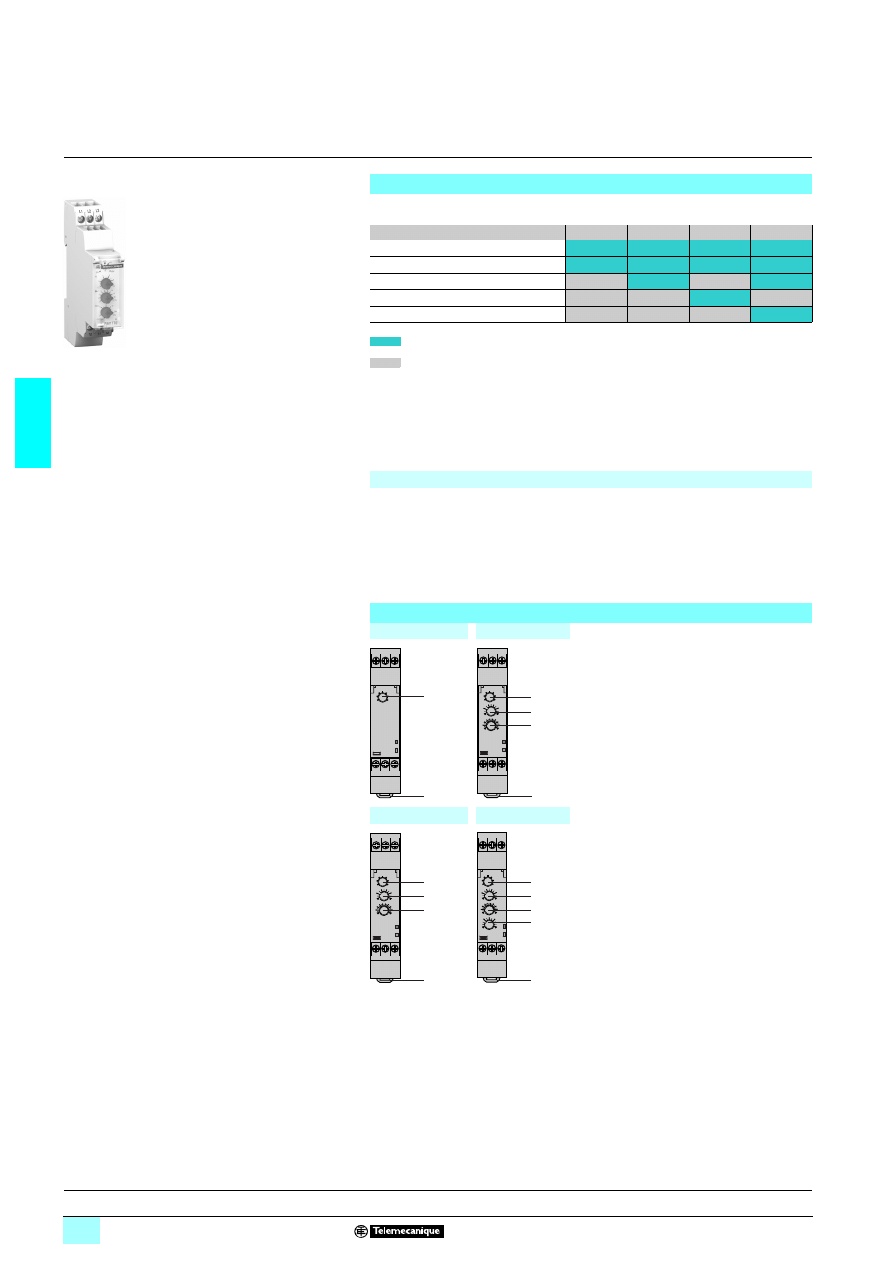
Application
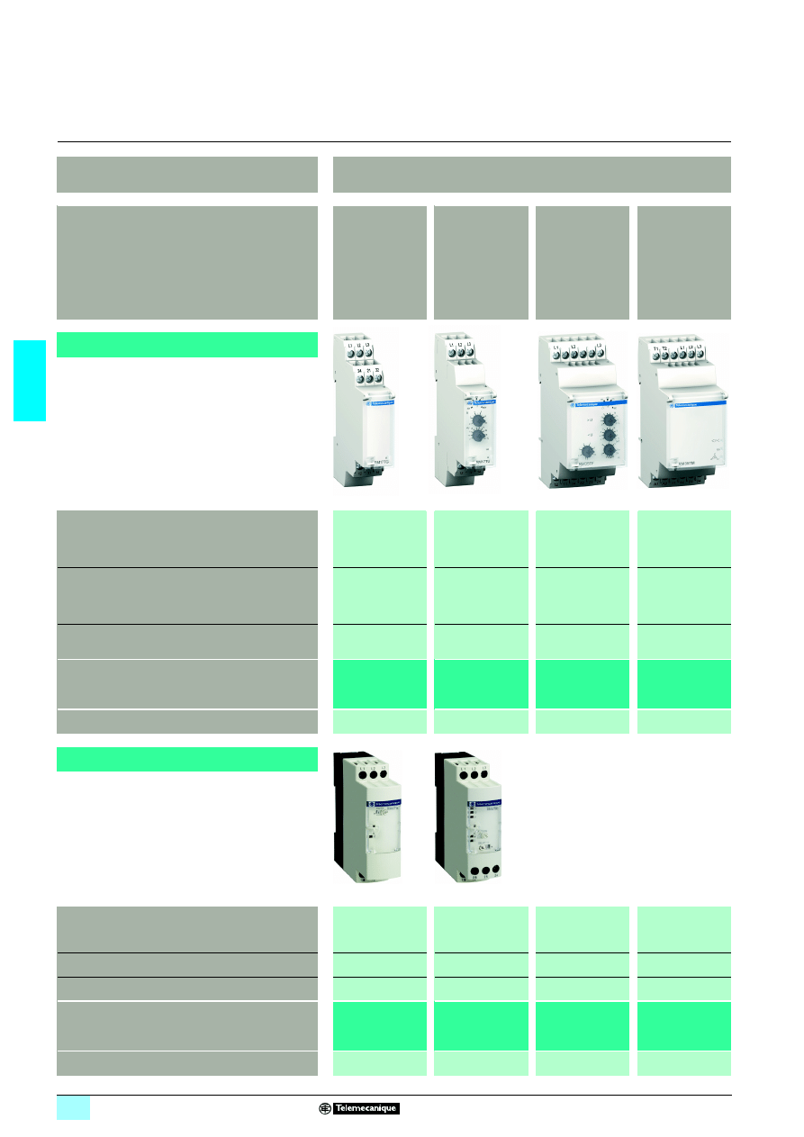
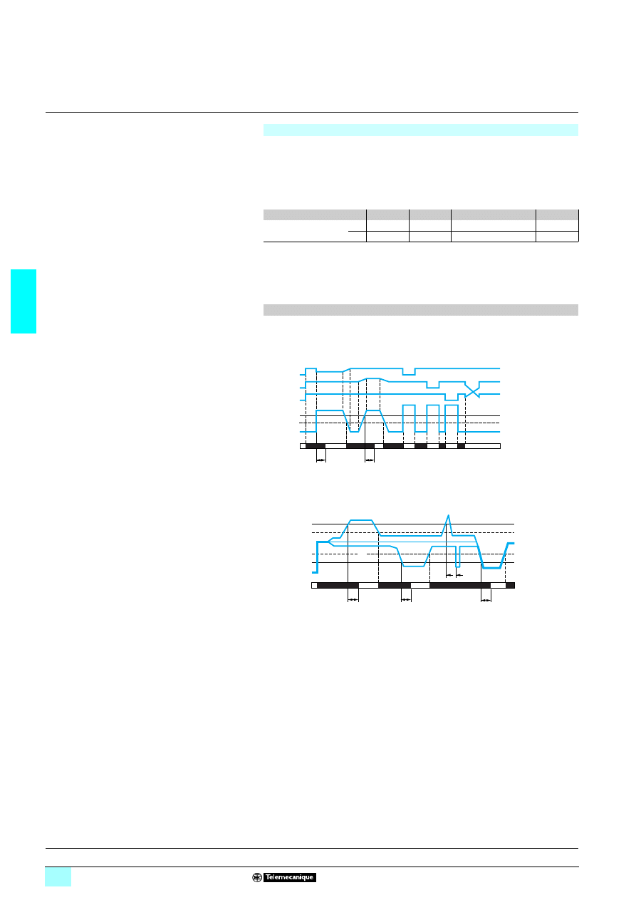
Control of 3-phase supplies
Functions
- Phase sequence
- Phase failure
- Asymmetry
- Phase sequence
- Phase failure
- Undervoltage
- Phase sequence
- Phase failure
- Asymmetry
- Overvoltage and
undervoltage
- Phase sequence
- Phase failure
- Motor temperature
Modular type
(17.5 or 35 mm width)
Values controlled
1 208…480 V
1 208…440 V
1 208…480 V
1 208…480 V
1 220…480 V
1 208…480 V
Output
1 or 2 C/O contacts
1 C/O
1 or 2 C/O contacts
2 N/O contacts
Size
17.5 mm
17.5 mm
17.5 or 35 mm
35 mm
Modular type relay
RM17 TG
10
RM17 TT00
RM17 TA00
RM17 TU00
RM17 TE00
RM35 TF30
RM35 TM
150
MW
Pages
3/6 to 3/17
3/10 to 3/17
3/10 to 3/21
3/22 to 3/27
Industrial type
(22.5 or 45 mm width)
Values controlled
1 220…440 V
1 220…240 V
1 380…440 V
1 220…440 V
1 220…240 V
1 380…440 V
–
–
Output
1 or 2 C/O contacts
2 C/O contacts
–
–
Size
22.5 mm
22.5 mm
–
–
Industrial type relay
RM4 TG20
RM4 TA
11
RM4 TU
11
RM4 TR
11
–
–
Pages
3/88 to 3/93
3/88 to 3/93
–
–
3/3
3
3
3
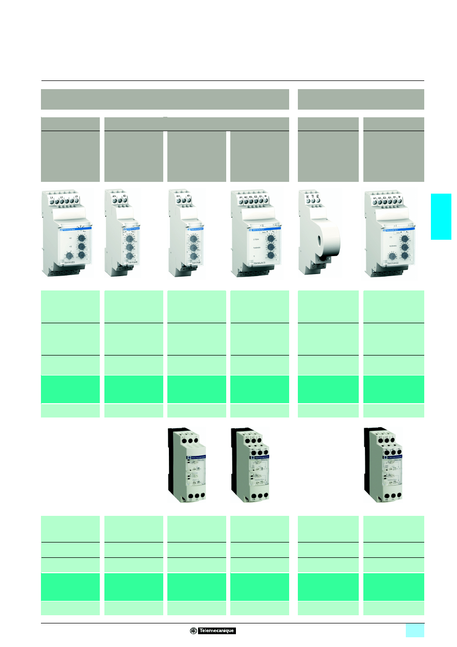
Voltage control
Current control
3-phase
Single-phase and d.c.
Integrated current
transformer
–
- Overvoltage and
undervoltage between
phases
- Overvoltage and
undervoltage between
phases and neutral
- Absence of
neutral / phase
- Overvoltage or
undervoltage
- Self-powered
- Overvoltage and
undervoltage in window
mode
- Self-powered
- Overvoltage or
undervoltage
- Overcurrent
- Overcurrent or
undercurrent
1 220…480 V
1 208…480 V
1 120…277 V
2 9…15 V
1/2 20…80 V
1/2 65…260 V
1/2 20…80 V
1/2 65…260 V
1/2 0,05…5 V
1/2 1…100 V
1/2 15…600 V
2…20 A
2…500 mA
0.15…15 A
1 C/O contact
or
1 C/O contact
+ 1 C/O contact
1 C/O contact
1 C/O contact
2 C/O contacts
1 C/O contact
2 C/O contacts
17.5 or 35 mm
17.5 mm
17.5 mm
35 mm
17.5 mm
35 mm
RM17 UB310
RM35 UB3
111
RM17 UAS1
1
RM17 UBE1
1
RM35 UA1
1MW
RM17 JC00MW
RM35 JA3
1MW
3/28 to 3/33
3/34 to 3/39
3/34 to 3/39
3/40 to 3/43
3/44 to 3/47
3/48 to 3/51
–
–
1/2 80…220 V
1/2 160…300 V
0.05…5 V
1…100 V
30…500 V
–
3 mA...1 A
0.3…15 A
–
–
2 C/O contacts
2 C/O contacts
–
1 or 2 C/O contacts
–
–
22.5 mm
22.5 mm
–
22.5 or 45 mm
–
–
RM4 UB3
1
RM4 UA3
1
RM4 UA1
1
–
RM4 JA01
RM4 JA3
1
–
–
3/94 to 3/97
3/98 to 3/103
–
3/104 to 3/109
3/4
3
Selection guide
(continued)
3
Zelio Control - modular and
industrial measurement
and control relays
3
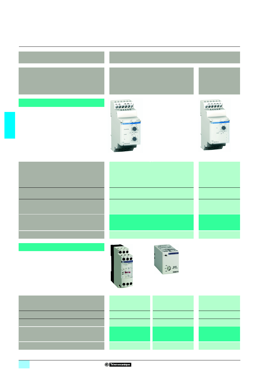
Application
Level control
Functions
By resistive probes
By discrete sensor
- Empty or fill
- Empty or fill
- Input for discrete sensor
AON: Contact/PNP/NPN
Modular type
(35 mm width)
Values controlled
0.25…5 k
Ω
5…100 k
Ω
0.05…1 M
Ω
–
Output
2 C/O contacts
1 C/O contact
Size
35 mm
35 mm
Modular type relay
RM35 LM33MW
RM35 LV14MW
Pages
3/52 to 3/57
3/52 to 3/57
Industrial type
(22,5 or 39 mm width)
Values controlled
2.5…50 k
Ω
5…100 k
Ω
25…500 k
Ω
5…100 k
Ω
–
Output
1 or 2 C/O contacts
1 or 2 C/O contacts
–
Size
22.5 mm
39 mm (plug-in 8 or 11-pin)
–
Industrial type relay
RM4 L
RM 84
–
Pages
3/110 to 3/115
3/116 to 3/119
–
3/5
3
3
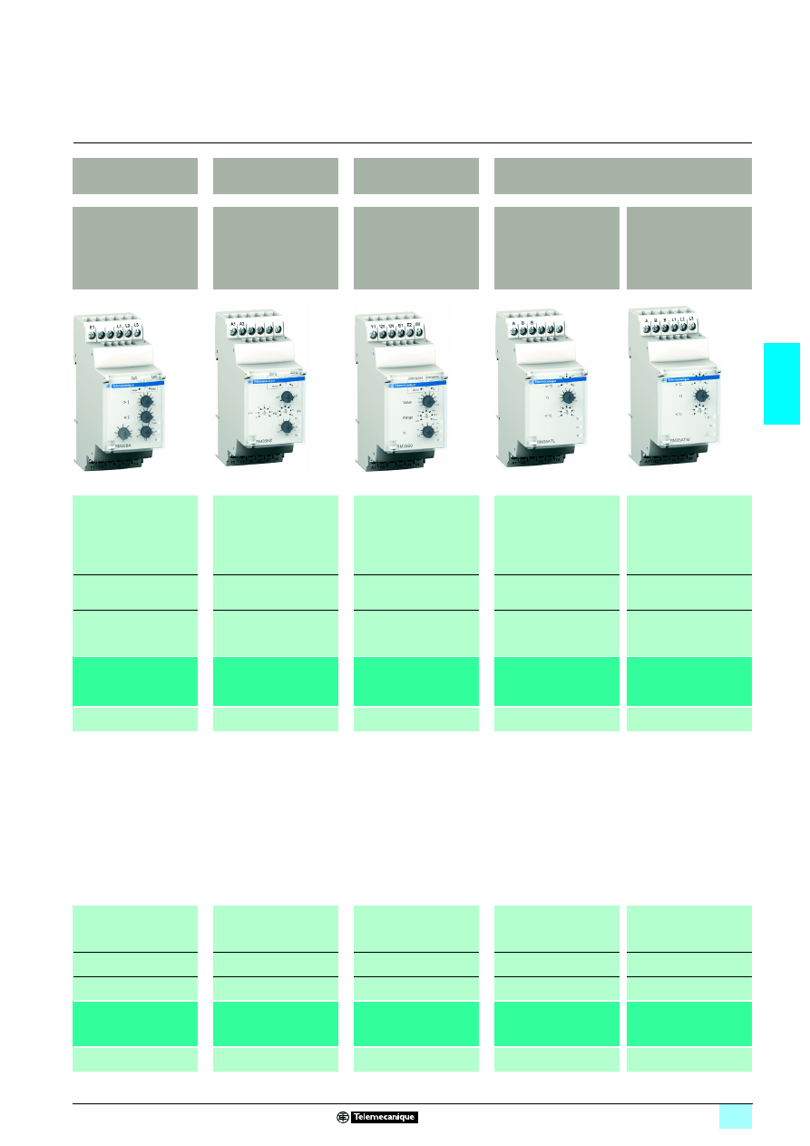
Pump control
Frequency control
Speed control
Temperature control for elevator machine rooms and
3-phase supplies
3-phase and single-phase
- Over-frequency and
under-frequency
- Over or under operating
rate / speed
- Machine room temperature
- Machine room temperature
- Phase failure and phase
sequence
- Overcurrent and
undercurrent
- Phase sequence
on 3-phase supply
- Phase failure
on 3-phase supply
Current: 1…10 A
3-phase
1 208…480 V
Single-phase
1 230 V
Mains supply: 50 or 60 Hz
High threshold: - 2…+ 10 Hz
Low threshold: - 10…+ 2 Hz
Time controlled between
pulses:
0.05…0.5 s, 0.1…1 s,
0.5…5 s, 1…10 s
0.1…1 min, 0.5…5 min,
1…10 min
Temperature
Low threshold: - 1…11 °C
High threshold: 34…46 °C
Temperature
Low threshold: - 1…11 °C
High threshold: 34…46 °C
3-phase supplies:
1 208…480 V
1 C/O contact
1 C/O contact
+ 1 C/O contact
1 C/O contact
1 C/O contact or
2 N/O contacts
2 N/O contacts
35 mm
35 mm
35 mm
35 mm
35 mm
RM35 BA10
RM35 HZ21FM
RM35 S0MW
RM35 ATL0MW
RM35 ATR5MW
RM35 ATW5MW
3/64 to 3/69
3/70 to 3/73
3/74 to 3/79
3/82 to 3/85
3/82 to 3/85
–
–
–
–
–
–
–
–
–
–
–
–
–
–
–
–
–
–
–
–
–
–
3/6
3
Presentation,
description
3
Zelio Control
-
modular measurement
and control relays
3
3-phase supply control relays
RM17 TG
Presentation
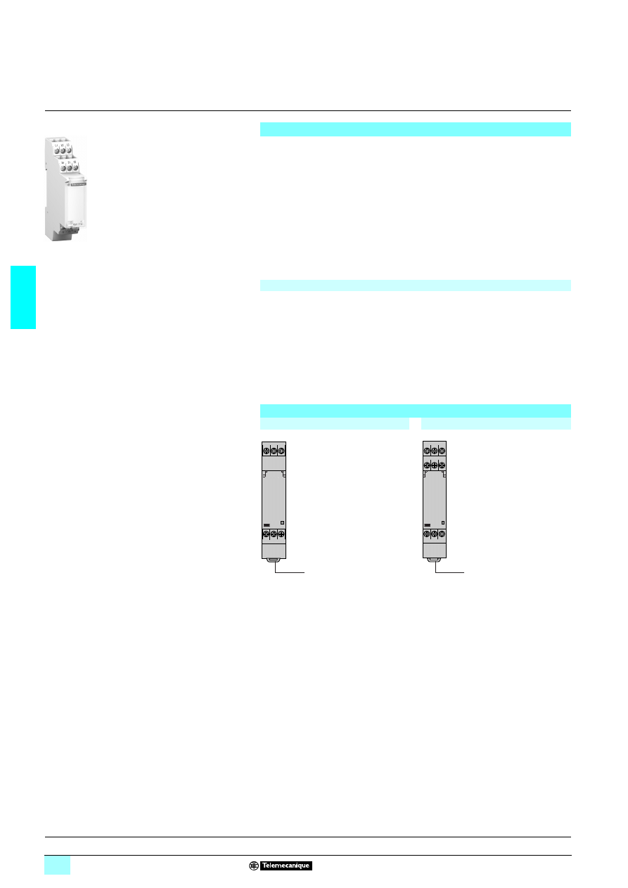
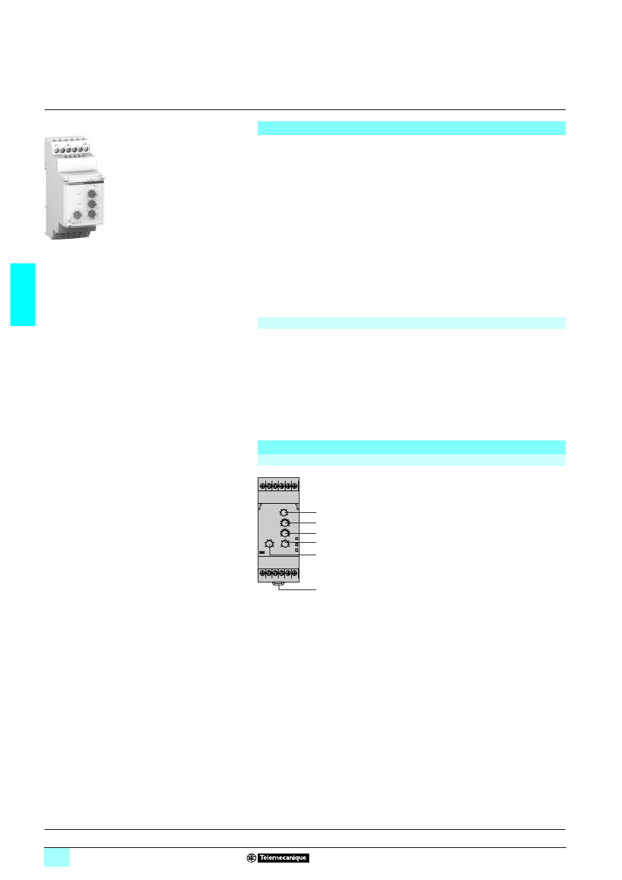
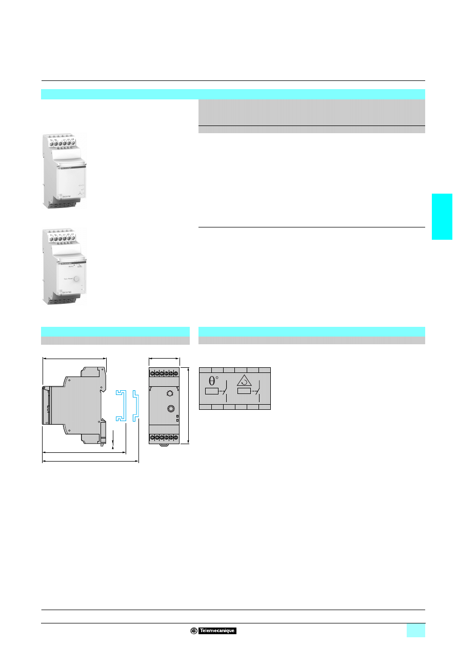
RM17 TG
30 measurement and control relays for 3-phase supplies monitor the
correct sequencing of phases L1, L2 and L3, as well as the total loss of one or more
of these phases.
These control relays accept different nominal 3-phase voltage values:
1 4 208…480 V for RM17 TG00,
1 4 208…440 V for RM17 TG20.
They monitor their own power supply, measured as a true rms value.
Control status is indicated by a LED.
The relays are designed for clip-on mounting on
5 rail
Applications
1 Control for connection of moving equipment (site equipment, agricultural
equipment, refrigerated trucks).
1 Control for protection of persons and equipment against the consequences of
reverse running (lifting, handling, elevators, escalators, etc.).
1 Control of sensitive 3-phase supplies.
1 Protection against the risk of a driving load (phase failure).
1 Normal/emergency power supply switching.
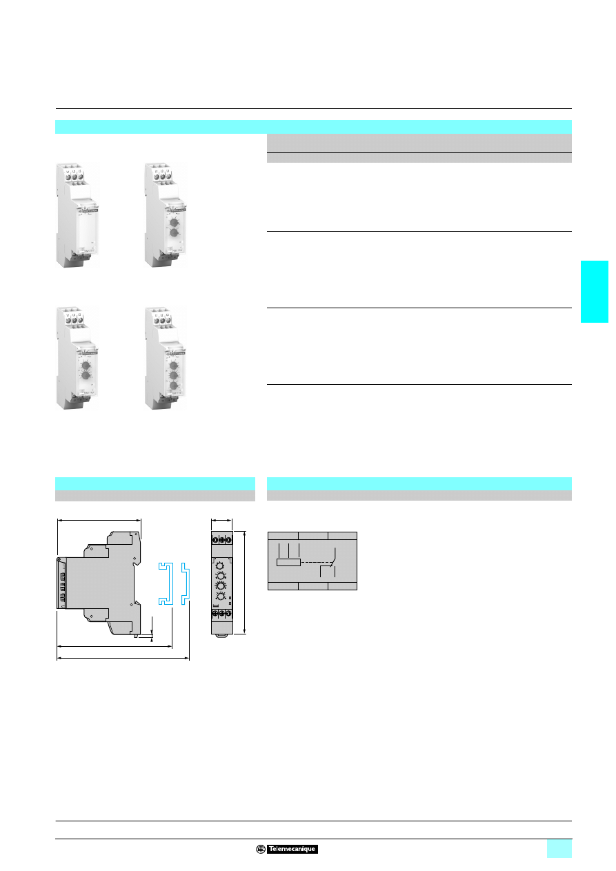
Description
RM17 TG00
RM17 TG20
1
Spring for clip-on mounting on 35 mm
5 rail.
R Yellow LED: indicates relay output state.
RM17 TG
10
10
56
62
L1 L2 L3
12 11 14
R
1
L1 L2 L3
24 21 22
12 11 14
R
1
Operation:
page 3/7
Characteristics:
page 3/8
References, dimensions :
page 3/9
3/7
3
Operation
3
Zelio Control
-
modular measurement
and control relays
3
3-phase supply control relays
RM17 TG
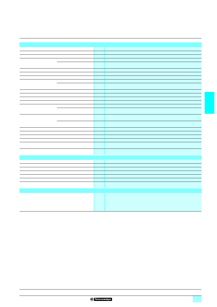
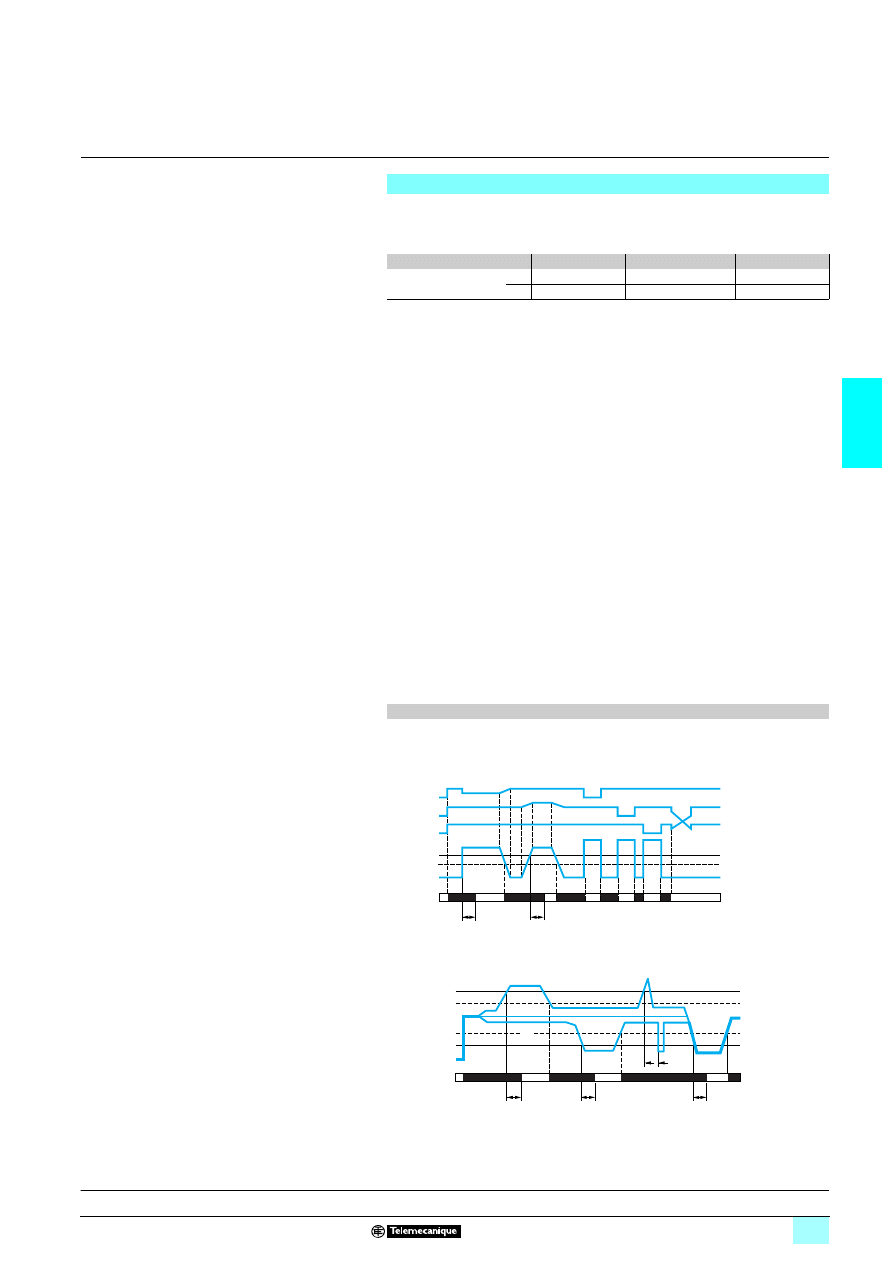
Operating principle
3-phase supply control relays monitor:
1 Correct sequencing of phases L1, L2 and L3.
Fault signalling is by LED.
Phase control relays: RM17 TG
11110
The relay monitors its own power supply.
The relay monitors:
1 Correct sequencing of the three phases,
1 Total loss of one or more of the phases.
When phase sequence and voltages are correct (>
4 183 V), the output relay(s) is/
are closed and the yellow LED is on.
In the event of a sequencing fault or total loss of one or more phases (detected as
soon as one of the voltages drops below 100 V) the relay opens instantly and the
LED goes out.
On energisation of the device with a fault measured, the relay stays open.
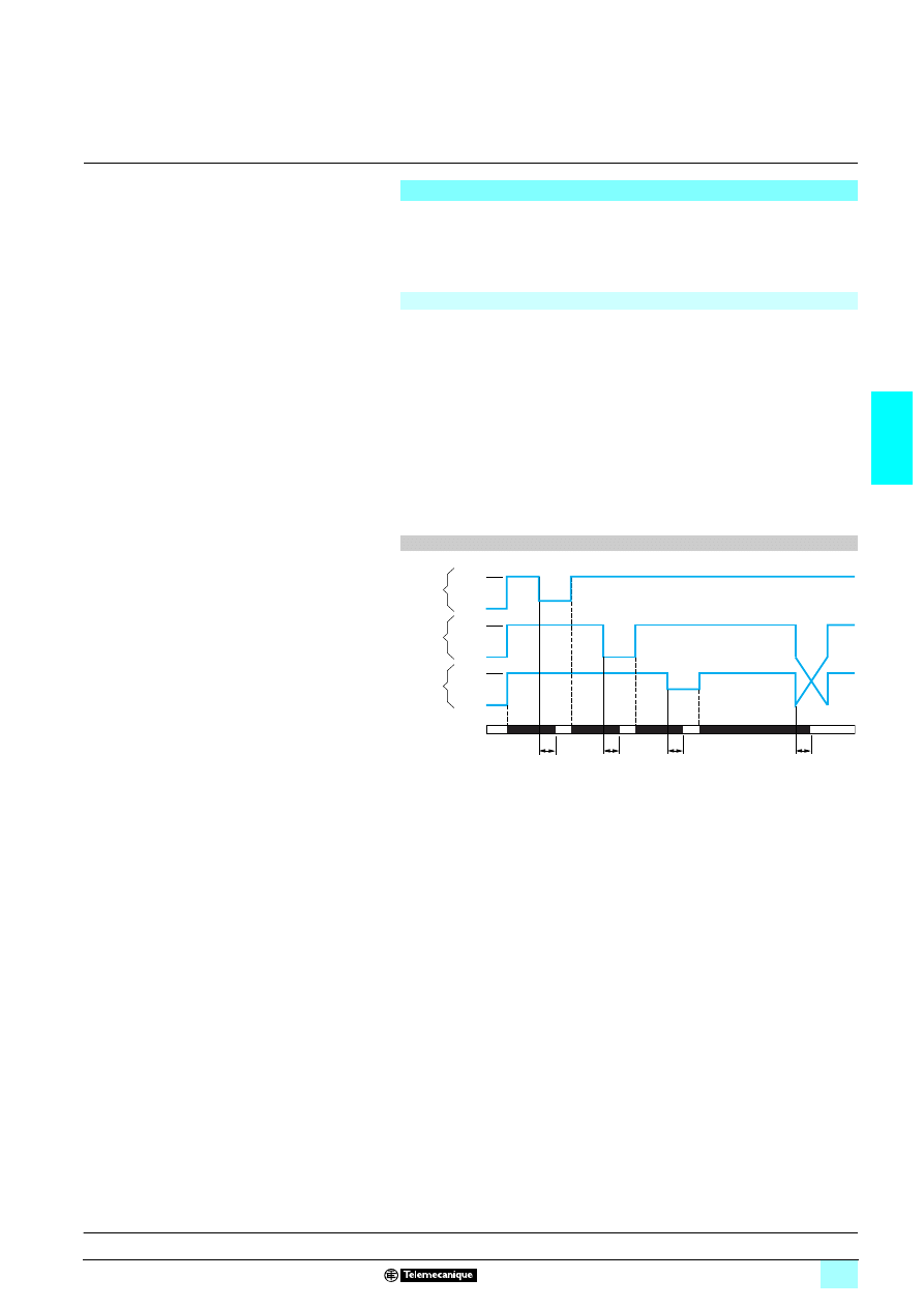
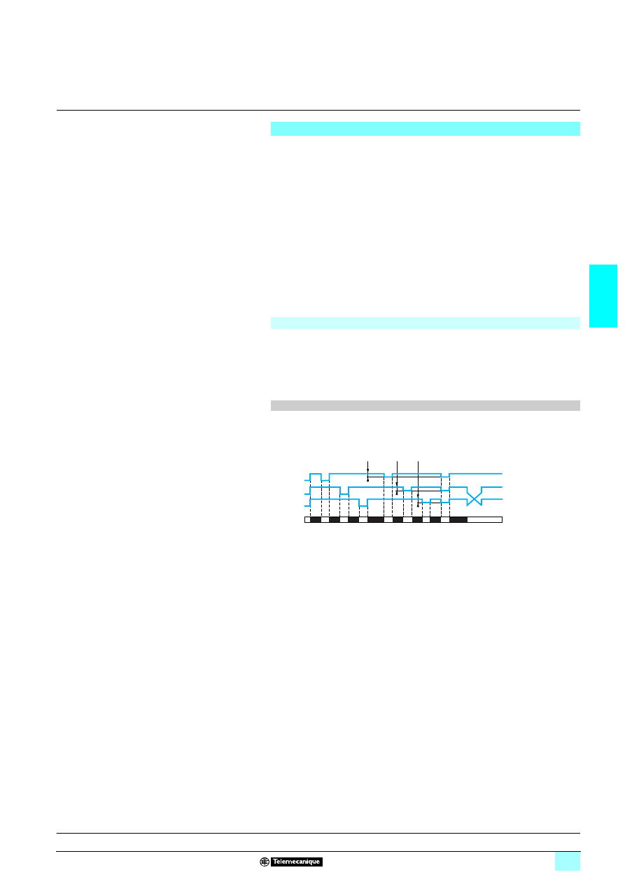
Function diagram
Tr: response time on appearance of a fault.
100 %
0 %
100 %
0 %
100 %
0 %
R - R1/R2
Tr
Tr
Tr
Tr
L3
L2
Phase L1
Phase L2
Phase L3
Relays
Presentation, description :
page 3/6
Characteristics:
page 3/8
References, dimensions :
page 3/9
3/8
3
Characteristics
3
Zelio Control
-
modular measurement
and control relays
3
3-phase supply control relays
RM17 TG
Environment characteristics
Conforming to standards
NF EN 60255-6 and IEC 60255-6
Product certifications
Pending
UL, CSA, GL, C-Tick, GOST
Marking
1
1
1
1 : 73/23/EEC and EMC 89/336/EEC
Ambient air temperature
around the device
Storage
°C
- 40…+ 70
Operation
°C
- 20…+ 50
Permissible relative humidity Conforming to IEC 60068-2-30
2 x 24 hours…+ 95 % RH at + 55 °C (without condensation)
Vibration resistance
Conforming to IEC 60068-2-6
0.035 mm from 10…150 Hz
Shock resistance
Conforming to IEC 60068-2-6
5 gn
Degree of protection
Conforming to IEC 60529
Casing
IP 30
Terminals
IP 20
Degree of pollution
Conforming to IEC 60664-1
3
Overvoltage category
Conforming to IEC 60664-1
III
Insulation resistance
Conforming to 60664-1/60255-5
> 500 M
Ω,
2 500 V
Rated insulation voltage
Conforming to IEC 60664-1
V
400
Insulation test voltage
Dielectric test
kV
2,
1 50 Hz, 1 min.
Shock wave
kV
4
Mounting position
without derating
In relation to normal
vertical mounting plane
Any position
Connection
Maximum c.s.a.
Conforming to IEC 60947-1
Solid cable without cable end
mm
2
1 conductor: 0.5…4 (AWG 20…AWG 11)
2 conductors: 0.5…2.5 (AWG 20…AWG 14)
Flexible cable with cable end
mm
2
1 conductor: 0.2…2.5 (AWG 24…AWG 12)
2 conductors: 0.2…1.5 (AWG 24…AWG 16)
Tightening torque
Conforming to IEC 60947-1
0.6…1 N.m / 5.3…8.8 Lbf.In
Housing material
Self-extinguishing plastic
Relay state indicator
Yellow LED
Mounting
Conforming to IEC/EN 60715
On 35 mm
3 rail
Supply characteristics
Relay type
RM17 TG00
RM17 TG20
Rated supply voltage Un
V
1 208…480
1 208…440
Operating range
V
1 183…528
1 183…484
Voltage limits
Of the power supply circuit
- 12 %, + 10 %
Frequency
Of the power supply circuit
Hz
50/60 Hz ± 10 %
Galvanic isolation, supply/measurement
No
Maximum power consumption
VA
141.8
Immunity to microbreaks
ms
60
Immunity to electromagnetic interference
Electromagnetic compatibility
Immunity NF EN 61000-6-2 / IEC 61000-6-2
Emission NF EN 61000-6-4
NF EN 61000-6-3
IEC 61000-6-4
IEC 61000-6-3
Input and measurement circuit characteristics
Guaranteed detection threshold for phase failure
V
<
1 100
Frequency of the measured
signal
Hz
50…60 ± 10 %
Output characteristics
Output type
1 C/O contact
2 C/O contacts
Contact type
Cadmium-free
Nominal current
A
5
Maximum switching voltage
V
1/2 250
Rated breaking capacity
VA
1250
Minimum breaking current
mA
10/
2 5 V
Electrical durability
1 x 10
5
operating cycles
1 x 10
4
operating cycles
Mechanical durability
30 x 10
6
operating cycles
Maximum operating rate
360 operations/hour under full load
Utilisation categories
Conforming to IEC 60947-5-1
AC-12, AC-13, AC-14, AC-15, DC-12, DC-13
Max. response time in the event of a fault
ms
100
Delay on pick-up
ms
500
Presentation, description :
page 3/6
Operation:
page 3/7
References, dimensions :
page 3/9
3/9
3
References,
dimensions,
schemes
3
Zelio Control
-
modular measurement
and control relays
3
3-phase supply control relays
RM17 TG
References
Function
Rated 3-phase
supply voltage
Output
Reference
Weight
V
kg
5 Phase sequence
5 Phase failure
1 208…480
1 C/O 5 A
RM17 TG00
0.080
1 208…440
2 C/O 5 A
RM17 TG20
0.085
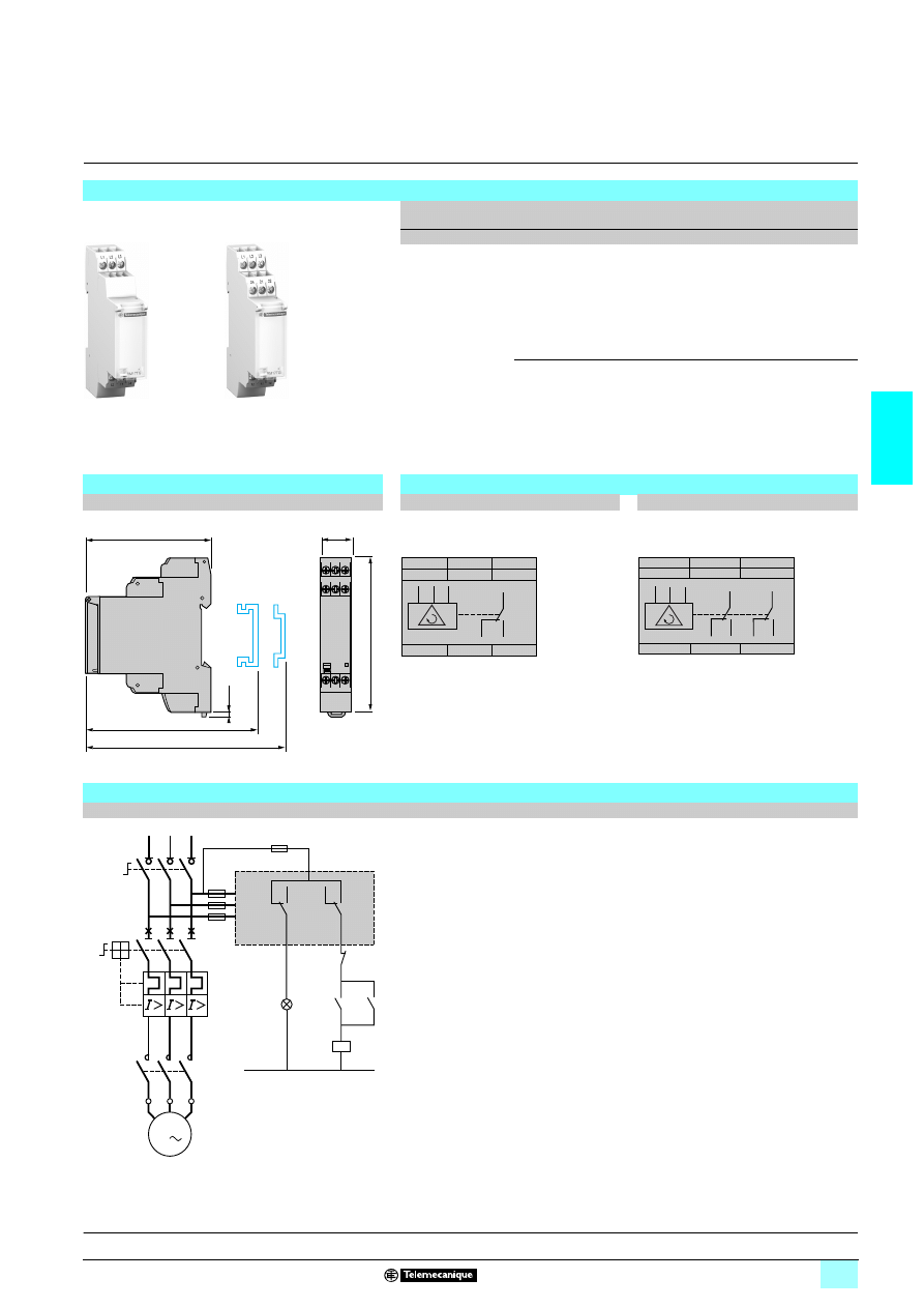
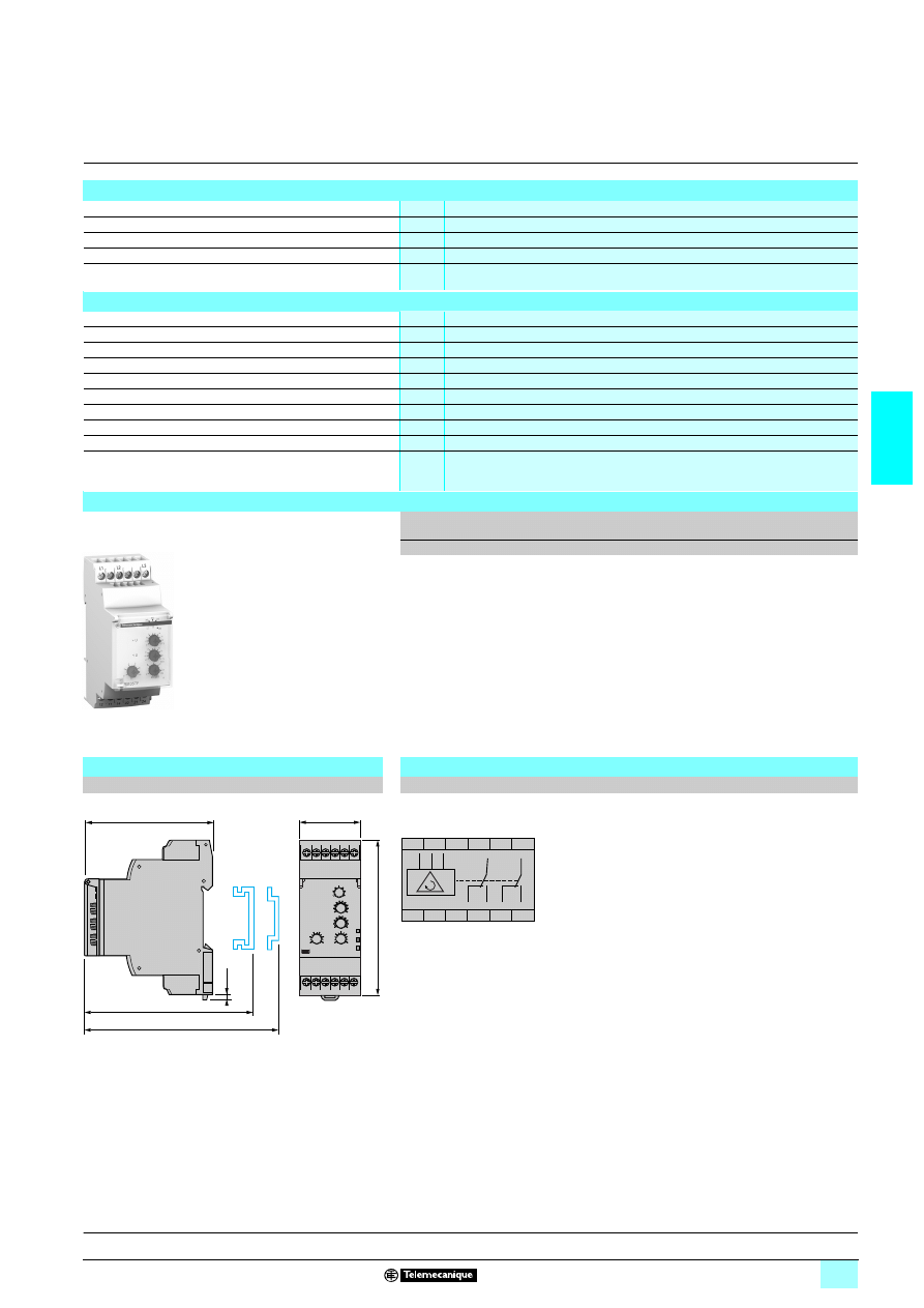
Dimensions
Schemes
RM17 TG
22220
RM17 TG00
RM17 TG20
mm/In.
Application scheme
Example
RM17 TG00
10
56
61
RM17 TG20
10
56
62
17,5
0.69
90/
3.54
72/
2.83
2,8
0.11
76/
2.99
72,5/
2.85
12
14
11
11
12
14
L1
L2
L3
L1
L3
L2
R
L1
L3
L2
24
11
14
22
21
12
21
11
12
14
24
L1
L2
L3
22
R1
R2
11
14
12
21
24
22
KM1
KM1
1/L1
2
3/L2
4
5/L3
6
Q1
2/T1
4/T2
6/T3
1
Q2
3
5
KM1
1
2
3
4
5
6
U1
W1
V1
M1
3
L3
L2
L1
RM17 TG20
N
fault
Start
Stop
Presentation, description :
page 3/6
Operation:
page 3/7
Characteristics
page 3/8
3/10
3
Presentation,
description
3
Zelio Control
-
modular measurement
and control relays
3
Multifunction 3-phase supply control relays
RM17 T
100
Presentation
RM17 TT, RM17 TA, RM17 TU and RM17 TE multifunction control relays monitor the
following on 3-phase supplies:
RM17 TT
RM17 TA
RM17 TU
RM17 TE
Sequence of phases L1, L2 and L3.
Phase failure with regeneration
Asymmetry
Undervoltage
Overvoltage and undervoltage
Function performed
Function not performed
These control relays accept different nominal 3-phase voltage values:
4 208… 480 V.
They monitor their own supply voltage, measured as a true rms value.
Settings are protected by a sealable cover.
Control status is indicated by a LED.
The relays are designed for clip-on mounting on
5 rail
Applications
1 Control for connection of moving equipment (site equipment, agricultural
equipment, refrigerated trucks).
1 Control for protection of persons and equipment against the consequences of
reverse running (lifting, handling, elevators, escalators, etc.).
1 Control of sensitive 3-phase supplies.
1 Protection against the risk of a driving load (phase failure).
1 Normal/emergency power supply switching.
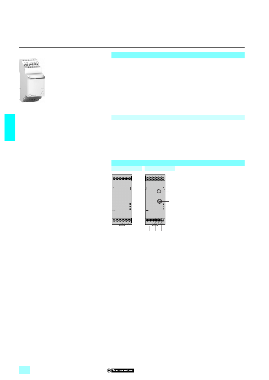
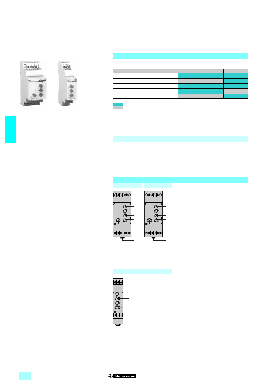
Description
RM17 TT00
RM17 TA00
1
Voltage range selector switch (208,
220, 380, 400, 415, 440 and 480 V).
2
Time delay adjustment potentiometer.
Tt
3a
Asymmetry threshold setting
potentiometer. Asy
3b
Undervoltage setting potentiometer.
<
U
3c
Undervoltage/overvoltage setting
potentiometer.
ΔU
4
Asymmetry threshold setting
potentiometer. Asy
RM17 TU00
RM17 TE00
5
Spring for clip-on mounting on 35 mm
5 rail.
Un Green LED: indicates that supply to the relay is on.
R
Yellow LED: indicates relay output state.
RM17 T
100
1
0
5
667
L1 L2 L3
12 11 14
MWG
1
5
Un
R
L1 L2 L3
12 11 14
1
2
3a
5
Un
R
L1 L2 L3
12 11 14
1
2
3b
5
Un
R
L1 L2 L3
12 11 14
1
2
3c
4
5
Un
R
Operation:
pages 3/11 to 3/14
Characteristics:
pages 3/15 and 3/16
References, dimensions :
page 3/17
3/11
3
Operation
3
Zelio Control
-
modular measurement
and control relays
3
Multifunction 3-phase supply control relays
RM17 T
100
Operating principle
3-phase supply control relays monitor:
1 The correct sequence of phases L1, L2, L3.
1 Phase failure, including in the case of voltage regeneration
1 Undervoltage from - 2…- 20 % of the supply voltage Un,
1 Overvoltage from 2…20 % of the supply voltage Un,
1 Asymmetry from 5…15 % of the supply voltage Un.
Fault signalling is by LED.
2222 Voltage selector switch :
2 Set the switch to the 3-phase supply voltage Un.
2 The position of this switch is only taken into account on energisation of the device.
2 If the switch position is changed while the device is operating, all the LEDs flash,
but the product continues to operate normally with the voltage selected at the time of
energisation preceding the change of position.
The LED's return to their normal state if the switch is returned to the original position
selected prior to the last energisation.
Phase control relay with voltage regeneration: RM17 TT00
2222 The relay monitors its own supply voltage Un:
2 The relay monitors:
- correct sequence of the three phases,
- failure of at least one of the three phases (U measured < 0.7 x Un).
2 In the event of a sequencing or phase failure fault, the relay opens instantly.
2 On energisation of the device with a fault measured, the relay stays open.
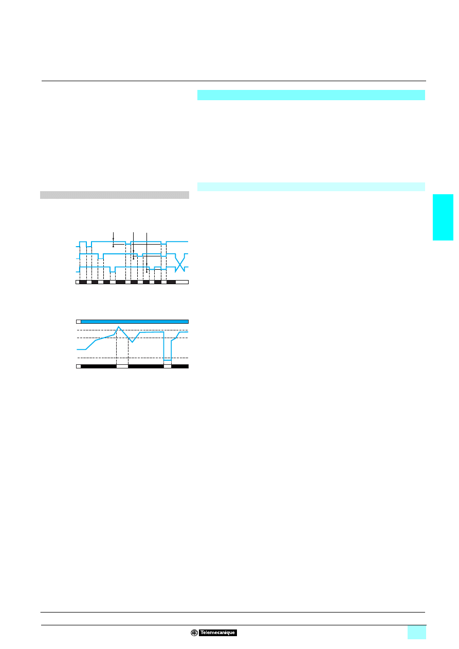
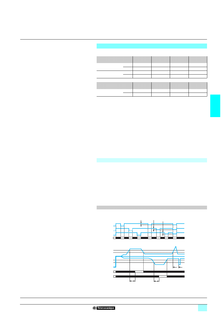
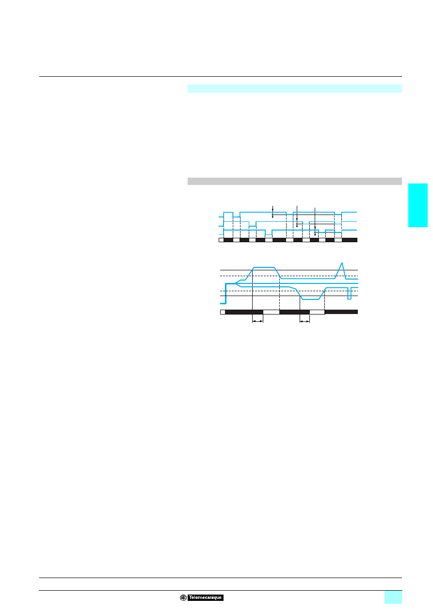
Function diagram
1 Function:
2 Sequence of phases L1, L2, L3.
2 Phase failure.
11-12
11-14
30 % Un 30 % Un
30 % Un
L3
L2
Phase L3
Phase L2
Phase L1
Relays
Presentation, description :
page 3/10
Characteristics:
pages 3/15 and 3/16
References, dimensions :
page 3/17
3/12
3
Operation
(continued)
3
Zelio Control
-
modular measurement
and control relays
3
Multifunction 3-phase supply control relays
RM17 T
100
Phase and asymmetry control relay: RM17 TA00
2222 The relay monitors its own supply voltage Un:
2 The relay monitors:
- correct sequence of the three phases,
- failure of at least one of the three phases (U measured < 0.7 x Un),
- asymmetry adjustable from 5…15 % of Un.
2 In the event of a sequencing or phase failure fault, the relay opens instantly.
2 In the event of an asymmetry fault, the relay opens at the end of the time delay
set by the user.
2 On energisation of the device with a fault measured, the relay stays open.
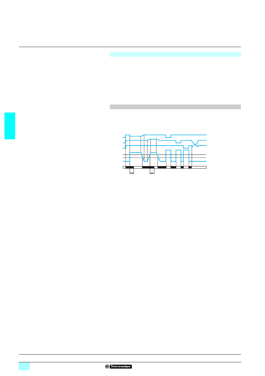
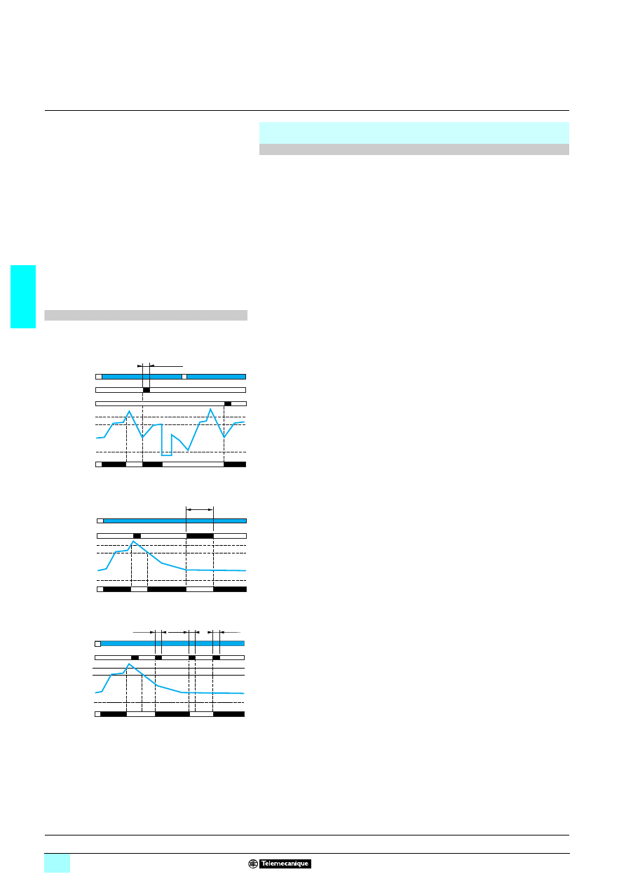
Function diagram
1 Function:
2 Sequence of phases L1, L2, L3.
2 Phase failure,
2 Asymmetry. Asy.
Tt : time delay after crossing of threshold (adjustable on front panel).
L2
L3
0 %
Tt
Tt
11-12
11-14
Phase L3
Phase L2
Phase L1
Hysteresis
Asymmetry
Relays
Presentation, description :
page 3/10
Characteristics:
pages 3/15 and 3/16
References, dimensions :
page 3/17
3/13
3
Operation
(continued)
3
Zelio Control
-
modular measurement
and control relays
3
Multifunction 3-phase supply control relays
RM17 T
100
Phase + undervoltage control relays: RM17 TU00
2222 The relay monitors its own supply voltage Un:
2 The relay monitors:
- correct sequence of the three phases,
- failure of at least one of the three phases (U measured < 0.7 x Un),
- undervoltage adjustable from - 2…- 20 % of Un (- 2… - 12 % in the range
4 3 x 208 V and - 2 %…- 17 % in the range 4 3 x 220 V due to the minimum
voltage
4 183 V).
2 In the event of a sequencing or phase failure fault, the relay opens instantly.
2 In the event of a voltage fault, the relay opens at the end of the time delay set by
the user.
2 On energisation of the device with a fault measured, the relay stays open.
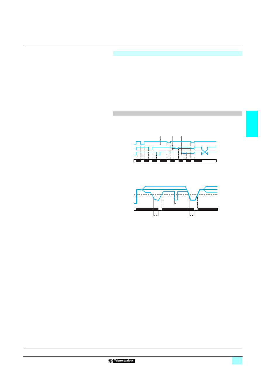
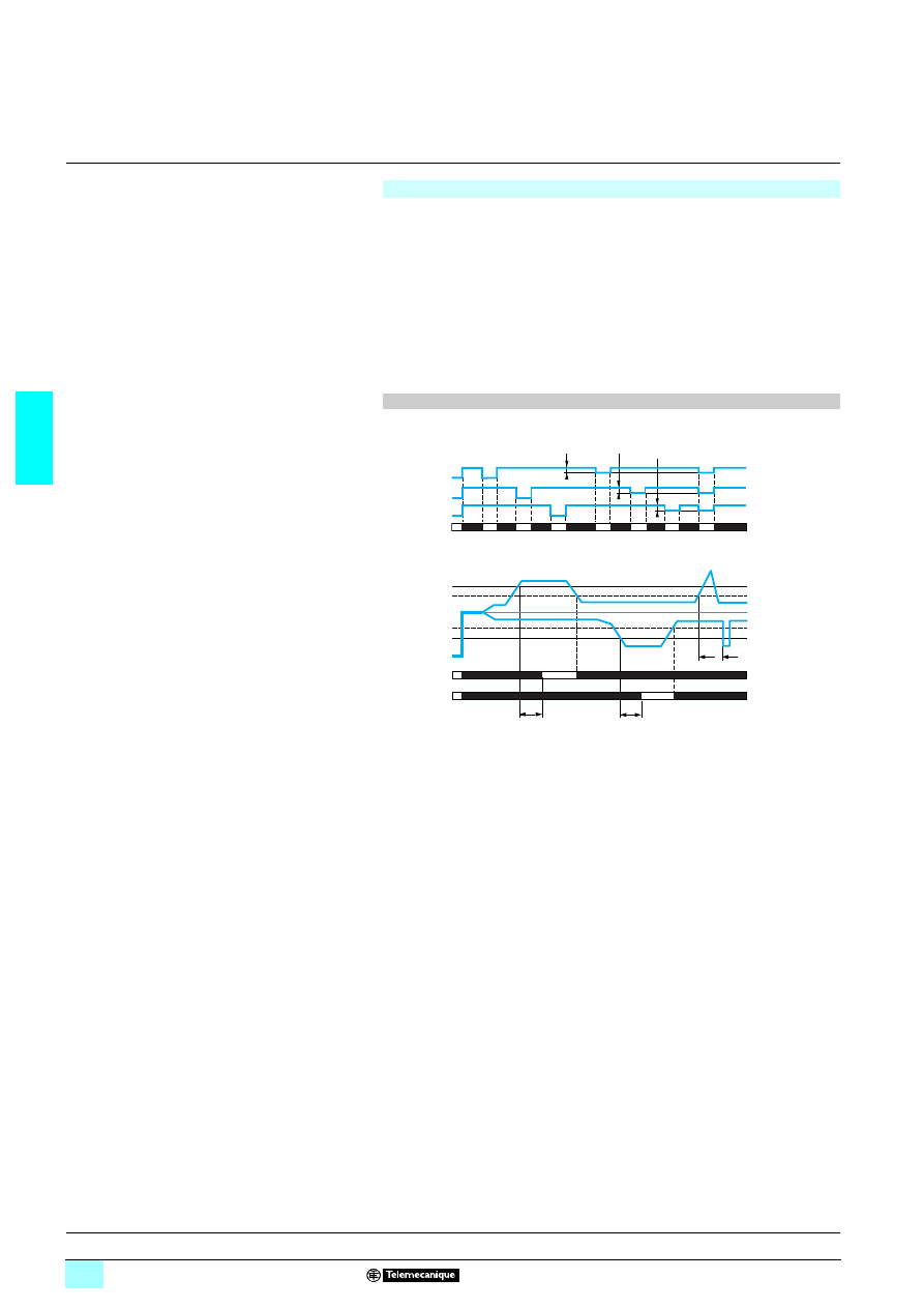
Function diagrams
1 Function:
26Sequence of phases L1, L2, L3.
26Phase failure.
2 Undervoltage control. U
<
Tt : time delay after crossing of threshold (adjustable on front panel)
11-12
11-14
30 % Un 30 % Un
30 % Un
L3
L2
Phase L3
Phase L2
Phase L1
Relays
L1/L2/L3
L1
L2
L3
L2
L3
L1
Tt
Tt
<
U
11-12
11-14
Threshold
Hysteresis
Relays
Phases
Presentation, description :
page 3/10
Characteristics:
pages 3/15 and 3/16
References, dimensions :
page 3/17
3/14
3
Operation
(continued)
3
Zelio Control
-
modular measurement
and control relays
3
Multifunction 3-phase supply control relays
RM17 T
100
Phase + asymmetry + undervoltage/overvoltage control relay: RM17 TE00
2222 The relay monitors its own supply voltage Un:
2 The relay monitors:
- correct sequence of the three phases,
- failure of at least one of the three phases (U measured < 0.7 x Un),
- asymmetry adjustable from 5…15 % of Un,
- the overvoltage and undervoltage difference in window mode, adjustable from
2…20 % of Un
Un
208 V
220 V
380, 400, 415, 440 V
480 V
Voltage threshold (%)
<
- 12…- 2
- 17…- 2
- 20…- 2
- 20…- 2
>
+ 2…+ 20
+ 2…+ 20
+ 2…+ 20
+ 2…+ 10
2 In the event of a sequencing or phase failure fault, the relay opens instantly.
2 In the event of an asymmetry or voltage fault, the relay opens at the end of the time
delay set by the user.
On energisation of the device with a fault measured, the relay stays open.
Function diagrams
1 Function:
26Sequence of phases L1, L2, L3.
26Phase failure,
26Asymmetry. Asy.
Tt : time delay after crossing of threshold (adjustable on front panel)
2 Control of overvoltage and undervoltage in window mode. U
> /
U
<
Tt : time delay after crossing of threshold (adjustable on front panel)
L2
L3
0 %
Tt
Tt
11-12
11-14
Phase L3
Phase L2
Phase L1
Hysteresis
Asymmetry
Relays
<
U
>
U
L1/L2/L3
L1
L2
L3
Tt
Tt
11-12
11-14
Tt
Threshold
Hysteresis
Hysteresis
Threshold
Relays
Presentation, description :
page 3/10
Characteristics:
pages 3/15 and 3/16
References, dimensions :
page 3/17
3/15
3
Characteristics
3
Zelio Control
-
modular measurement
and control relays
3
Multifunction 3-phase supply control relays
RM17 T
100
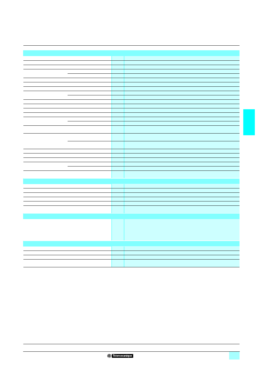
Environment characteristics
Conforming to standards
NF EN 60255-6 and IEC 60255-6
Product certifications
Pending
UL, CSA, GL, C-Tick, GOST
Marking
6: 73/23/EEC and EMC 89/336/EEC
Ambient air temperature
around the device
Storage
°C
- 40…+ 70
Operation
°C
- 20…+ 50
Permissible relative humidity Conforming to IEC 60068-2-30
2 x 24 hours…+ 95 % RH at + 55 °C (without condensation)
Vibration resistance
Conforming to IEC 60068-2-6
0.035 mm from 10…150 Hz
Shock resistance
Conforming to IEC 60068-2-6
5 gn
Degree of protection
Conforming to IEC 60529
Casing
IP 30
Terminals
IP 20
Degree of pollution
Conforming to IEC 60664-1
3
Overvoltage category
Conforming to IEC 60664-1
III
Insulation resistance
Conforming to 60664-1/60255-5
> 500 M
Ω,
2 500 V
Rated insulation voltage
Conforming to IEC 60664-1
V
400
Insulation test voltage
Conforming to
IEC 60664-1/60255-5
Dielectric test
kV
2,
1 50 Hz, 1 min.
Shock wave
kV
4 (1.2/50 µs)
Connection
Maximum c.s.a.
Conforming to IEC 60947-1
Solid cable without cable end
mm
2
1 conductor: 0.5…4 (AWG 20…AWG 11)
2 conductors: 0.5…2.5 (AWG 20…AWG 14)
Flexible cable with cable end
mm
2
1 conductor: 0.2…2.5 (AWG 24…AWG 12)
2 conductors: 0.2…1.5 (AWG 24…AWG 16)
Tightening torque
Conforming to IEC 60947-1
0.6…1 N.m / 5.3…8.8 Lbf.In
Housing material
Self-extinguishing plastic
Power ON indicator
Green LED
Relay state indicator
Yellow LED (flashes during the time delay on crossing the threshold)
Mounting position
without derating
In relation to normal
vertical mounting plane
Any position
Mounting
Conforming to IEC/EN 60715
On 35 mm
3 rail
Supply characteristics
Rated supply voltage Un
V
1 208…480
Operating range
V
1 183…528
Voltage limits
Of the power supply circuit
- 12 %, + 10 %
Frequency
Of the power supply circuit
Hz
50/60 Hz ± 10 %
Galvanic isolation, supply/measurement
No
Maximum power consumption at Un
VA
141.8
Immunity to microbreaks
ms
10
Immunity to electromagnetic interference
Electromagnetic compatibility
Immunity NF EN 61000-6-2 / IEC 61000-6-2
Emission NF EN 61000-6-4
NF EN 61000-6-3
IEC 61000-6-4
IEC 61000-6-3
Presentation, description :
page 3/10
Operation:
pages 3/11 to 3/14
References, dimensions :
page 3/17
3/16
3
Characteristics
(continued)
3
Zelio Control
-
modular measurement
and control relays
3
Multifunction 3-phase supply control relays
RM17 T
100
Measurement circuit and input characteristics
Measurement range
V
1 183…528
Phase-phase voltage selection
V
208, 220, 380, 400, 415, 440 , 480
Frequency of the measured signal
50…60 Hz ± 10 %
Maximum measuring cycle
ms
150/measurement as true rms value
Adjustment of voltage threshold
2…20 % of Un selected
(- 2…- 12 % in the range 3 x
1 208 V, - 2…- 17 % in the range 3 x 1 220 V /
+ 2…+ 10 % in the range 3 x
1 480 V)
Fixed hysteresis
2 % of Un
Adjustment of asymmetry threshold
5…15 % of Un selected
Fixed hysteresis
2 % of Un
Setting accuracy
± 10 % of the full scale value
Repeat accuracy (with constant parameters)
± 0.5 %
Measurement error with voltage variation
V
< 1 % over the whole range
Measurement error with temperature variation
< 0.05 % / °C
Maximum regeneration (phase failure)
0.7 Un
Time delay characteristics
Time delay on crossing the threshold
s
0.1…10, 0 + 10 %
Repeat accuracy (with constant parameters)
± 3 %
Reset time
ms
1500
Response time in the event of a fault
ms
< 200
Delay on pick-up
ms
500
Output characteristics
Type of output
1 C/O contact
Contact type
Cadmium-free
Nominal current
A
5
Maximum switching voltage
V
1/2 250
Rated breaking capacity
VA
1250
Minimum breaking current
mA
10/
2 5 V
Maximum breaking current
A
1/2 5
Electrical durability
1 x 10
5
operating cycles
Mechanical durability
30 x 10
6
operating cycles
Maximum operating rate
360 operations/hour under full load
Utilisation categories
Conforming to IEC 60947-5-1
AC-12, AC-13, AC-14, AC-15, DC-12, DC-13
Presentation, description :
page 3/10
Operation:
pages 3/11 to 3/14
References, dimensions :
page 3/17
3/17
3
References,
dimensions,
scheme
3
Zelio Control
-
modular measurement
and control relays
3
Multifunction 3-phase supply control relays
RM17 T
100
References
Function
Rated 3-phase
supply voltage
Output
Reference
Weight
V
kg
5 Phase sequence
5 Phase failure
1 208…480
1 C/O
5 A
RM17 TT00
0.080
5 Phase sequence
5 Phase failure
5 Asymmetry
1 208…480
1 C/O
5 A
RM17 TA00
0.080
5 Phase sequence
5 Phase failure
5 Undervoltage
1 208…480
1 C/O
5 A
RM17 TU00
0.080
5 Phase sequence
5 Phase failure
5 Asymmetry
5 Undervoltage and
overvoltage in
window mode
1 208…480
1 C/O
5 A
RM17 TE00
0.080
Dimensions
Scheme
RM17 T
222200
RM17 T
222200
mm/In.
RM17 TT00
RM17 TA00
10
56
66
10
56
63
RM17 TU00
RM17 TE00
10
566
5
10
566
7
2,8
0.11
17,5
0.69
90/
3.54
L1 L2 L3
12 11 14
72/
2.83
76/
2.99
72,5/
2.85
12
14
11
11
12
14
L1
L2
L3
L1
L3
L2
R
Presentation, description :
page 3/10
Operation:
pages 3/11 to 3/14
Characteristics:
pages 3/15 and 3/16
3/18
3
Presentation,
description
3
Zelio Control
-
modular measurement
and control relays
3
Multifunction 3-phase supply control relays
RM35 TF
Presentation
Measurement and control relay RM35 TF30 monitors the following on 3-phase
supplies: the correct sequencing of phases L1, L2 and L3, failure of one or more of
these phases, asymmetry, as well as overvoltage and undervoltage with
independent settings.
Multi-voltage product.
This control relay accepts different nominal 3-phase voltage values:
4 220… 480 V.
It monitors its own supply voltage, measured as a true rms value.
Settings are protected by a sealable cover.
Control status is indicated by a LED.
The relay is designed for clip-on mounting on
5 rail.
Applications
1 Control for connection of moving equipment (site equipment, agricultural
equipment, refrigerated trucks).
1 Control for protection of persons and equipment against the consequences of
reverse running (lifting, handling, elevators, escalators, etc.).
1 Control of sensitive 3-phase supplies.
1 Protection against the risk of a driving load (phase failure).
1 Normal/emergency power supply switching.
Description
RM35 TF
1
Voltage range selector switch (220, 380, 400, 415,
440 and 480 V).
2
Overvoltage setting potentiometer.
>
U
3
Undervoltage setting potentiometer.
<
U
4
Asymmetry threshold setting potentiometer.
Asym
5
Time delay adjustment potentiometer. Tt
6
Spring for clip-on mounting on 35 mm
5 rail.
Def. Yellow LED: indicates fault present status (on for asymmetry, flashing for
overvoltage and undervoltage).
Un Green LED: indicates that supply to the relay is on.
R
Yellow LED: indicates relay output state.
RM35 TF30
10
56
70
L1
12
22 21 24
11 14
L3
L2
Def.
Un
R
1
2
3
4
5
6
Operation:
page 3/19
Characteristics:
page 3/20
References, dimensions :
page 3/21
3/19
3
Operation
3
Zelio Control
-
modular measurement
and control relays
3
Multifunction 3-phase supply control relays
RM35 TF
Operating principle
3-phase supply control relay RM35 TF30 monitors:
1 The correct sequence of phases L1, L2, L3.
1 Phase failure,
1 Undervoltage and overvoltage in window mode:
Un
220 V
380, 400, 415, 440 V
480 V
Voltage threshold (%)
<
- 12…- 2
- 20…- 2
- 20…- 2
>
+ 2…+ 20
+ 2…+ 20
+ 2…+ 10
1 Asymmetry from 5…15 % of the supply voltage Un.
Fault signalling is by LED.
2222 Voltage selector switch :
2 Set the switch to the 3-phase supply voltage Un.
2 The position of this switch is only taken into account on energisation of the device.
2 If the switch position is changed while the device is operating, all the LEDs flash,
but the product continues to operate normally with the voltage selected at the time of
energisation preceding the change of position.
2 The LED's return to their normal state if the switch is returned to the original
position selected prior to the last energisation.
2222 The relay monitors its own supply voltage Un:
2 The relay monitors:
- correct sequence of the three phases,
- failure of at least one of the three phases (U measured < 0.7 x Un),
- asymmetry, adjustable from 5 to 15 % of Un,
- the undervoltage, adjustable from - 2…- 20 % of Un
(- 2…- 12 % in the range
4 3 x 220 V)
- the overvoltage, adjustable from + 2…+ 20 % of Un
(+ 2…+ 10 % in the range
4 3 x 480 V due to the maximum voltage 4 528 V).
2 In the event of a sequencing or phase failure fault, the relay opens instantly.
2 In the event of an asymmetry or voltage fault, the relay opens at the end of the time
delay set by the user.
2 On energisation of the device with a fault measured, the relay stays open.
Function diagrams
1 Function:
26Sequence of phases L1, L2, L3.
26Phase failure,
26Asymmetry.
Tt: time delay after crossing of threshold (adjustable on front panel)
2 Control of overvoltage and undervoltage in window mode.
<
U
<
Tt: time delay after crossing of threshold (adjustable on front panel)
L2
L3
0 %
Tt
Tt
Phase L3
Phase L2
Phase L1
Hysteresis
Asymmetry
Relay
<
U
>
U
L1/L2/L3
L1
L2
L3
Tt
Tt
Tt
Threshold
Hysteresis
Hysteresis
Threshold
Relay
Presentation, description :
page 3/18
Characteristics:
page 3/20
References, dimensions :
page 3/21
3/20
3
Characteristics
3
Zelio Control
-
modular measurement
and control relays
3
Multifunction 3-phase supply control relays
RM35 TF
Environment characteristics
Conforming to standards
NF EN 60255-6 and IEC 60255-6
Product certifications
Pending
UL, CSA, GL, C-Tick, GOST
Marking
1
1
1
1: 73/23/EEC and EMC 89/336/EEC
Ambient air temperature
around the device
Storage
°C
- 40…+ 70
Operation
°C
- 20…+ 50
Permissible relative humidity Conforming to IEC 60068-2-30
2 x 24 hours…+ 95 % RH at + 55 °C (without condensation)
Vibration resistance
Conforming to IEC 60068-2-6
0.035 mm from 10…150 Hz
Shock resistance
Conforming to IEC 60068-2-27
5 gn
Degree of protection
Conforming to IEC 60529
Casing
IP 30
Terminals
IP 20
Degree of pollution
Conforming to IEC 60664-1
3
Overvoltage category
Conforming to IEC 60664-1
III
Insulation resistance
Conforming to IEC 60664-1,
60255-5
> 500 M
Ω,
2 500 V
Rated insulation voltage
Conforming to IEC 60664-1
V
400
Insulation test voltage
Dielectric test
kV
2,
1 50 Hz, 1 min.
Shock wave
kV
4
Mounting position
without derating
In relation to normal
vertical mounting plane
Any position
Connection
Maximum c.s.a.
Conforming to IEC3 60947-1
Solid cable without cable end
mm
2
1 conductor: 0.5…4 (AWG 20…AWG 11)
2 conductors: 0.5…2.5 (AWG 20…AWG 14)
Flexible cable with cable end
mm
2
1 conductor: 0.2…2.5 (AWG 24…AWG 12)
2 conductors: 0.2…1.5 (AWG 24…AWG 16)
Tightening torque
Conforming to IEC 60947-1
0.6…1 N.m / 5.3…8.8 Lbf.In
Housing material
Self-extinguishing plastic
Power ON indicator
Green LED (this LED is off in the event of phase failure)
Relay state indicator
Yellow LED (this LED flashes during the time delay on crossing the threshold)
Fault indication
Yellow LED
- this LED lights up in the event of asymmetry,
- this LED flashes in the event of overvoltage or undervoltage
Mounting
Conforming to IEC/EN 60715
On 35 mm
3 rail
Supply characteristics
Rated supply voltage Un
V
1 3 x 220… 3 x 480
Operating range
V
1 194…528
Voltage limits
Of the power supply circuit
- 12 %, + 10 %
Frequency
Of the power supply circuit
50/60 Hz ± 10 %
Galvanic isolation, supply/measurement
No
Maximum power consumption
VA
142.9
Immunity to microbreaks
ms
10
Immunity to electromagnetic interference
Electromagnetic compatibility
Immunity NF EN 61000-6-2 / IEC 61000-6-2
Emission NF EN 61000-6-4
NF EN 61000-6-3
IEC 61000-6-4
IEC 61000-6-3
Input and measurement circuit characteristics
Measurement range
V
1 194…528
Phase-phase voltage selection
V
220, 380, 400, 415, 440, 480
Guaranteed detection threshold for phase failure
V
194
Frequency of the measured signal
Hz
50…60 ± 10 %
Maximum measuring cycle
ms
140/measurement as true rms value
Adjustment of voltage threshold
2…20 % of Un selected
(- 12…- 2 % in the range 3 x
1 220 V and - 20…- 2 % in the ranges 3 x 1 380…480 V)
(+ 2…+ 20 % in the ranges 3 x
1 220…440 V and + 2…+ 10 % in the range 3 x 1 480 V)
Fixed hysteresis
2 % of Un
Adjustment of asymmetry threshold
5…15 % of Un selected
Setting accuracy
± 10 % of the threshold setting (of the full scale value)
Repeat accuracy (with constant parameters)
± 0.5 %
Measurement error with voltage variation
< 1 % over the whole range
Measurement error with temperature variation
0.05 % / °C
Presentation, description :
page 3/18
Operation:
page 3/19
References, dimensions :
page 3/21
3/21
3
Characteristics
(continued)
reference,
dimensions,
scheme
3
Zelio Control
-
modular measurement
and control relays
3
Multifunction 3-phase supply control relays
RM35 TF
Time delay characteristics
Time delay on crossing the threshold
s
0.1…10. 0 + 10 %
Repeat accuracy (with constant parameters)
± 0.3 %
Reset time
ms
1500 max at 480 V
Response time in the event of a fault
ms
< 200
Delay on pick-up
ms
500
Output characteristics
Type of output
2 C/O contacts
Contact type
Cadmium-free
Maximum switching voltage
V
1/2 250
Rated breaking capacity
VA
1250
Maximum breaking current
A
1/2 5
Minimum breaking current
mA
10 /
2 5 V
Mechanical durability
30 x 10
6
operating cycles
Electrical durability
1 x 10
5
operating cycles
Maximum operating rate
360 operations/hour under full load
Utilisation categories
Conforming to IEC 60947-5-1
AC-12, AC-13, AC-14, AC-15, DC-12, DC-13
Reference
Function
Rated 3-phase
supply voltage
Output
Reference
Weight
V
kg
5 Phase sequence
5 Phase failure
5 Asymmetry
5 Undervoltage and
overvoltage in
window mode
1 220…480
2 C/O 5 A
RM35 TF30
0.130
Dimensions
Scheme
RM35 TF30
RM35 TF30
mm/In.
RM35 TF30
1
056
70
2,8
0.11
76/
2.99
72,5/
2.85
72/
2.83
90/
3.54
35/
1.38
L1
L2
L3
L1
L2
R
L3
24
22
14
12
21
11
11
21
24
12
22
14
Presentation, description :
page 3/18
Operation :
page 3/19
Characteristics:
page 3/20
3/22
3
Presentation,
description
3
Zelio Control
-
modular measurement
and control relays
3
3-phase supply and motor temperature
control relays RM35 TM
Presentation
Motor temperature measurement and control relays RM35 TM50MW and
RM35 TM250MW monitor the following, on 3-phase supplies: correct sequencing of
phases L1, L2 and L3, phase failure and motor temperature via PTC probes (with or
without memory).
The "phase" and "temperature" control functions are independent of each other.
These control relays accept different nominal 3-phase voltage values:
46208… 480 V.
They also detect line breaks or short-circuiting of the probes.
A version with fault memory and Test/Reset function is available.
Settings are protected by a sealable cover.
Control status is indicated by a LED.
The relays are designed for clip-on mounting on
5 rail
Applications
1 Control for connection of moving equipment (site equipment, agricultural
equipment, refrigerated trucks).
1 Control for protection of persons and equipment against the consequences of
reverse running (lifting, handling, elevators, escalators, etc.).
1 Control of sensitive 3-phase supplies.
1 Protection against the risk of a driving load (phase failure).
1 Normal/emergency power supply switching.
Description
RM35 TM50MW
RM35 TM250MW
1
Spring for clip-on mounting on 35 mm
5 rail.
2
Temperature contact (11-14).
3
Phase contact (21-24).
4
Configuration: selection of temperature
control operating mode (with or without
memory).
Memory - No Memory
5
Pushbutton (activation of temperature
control) Test/Reset
R1 Yellow LED: temperature relay state indicator.
Un Green LED: power ON indicator.
R2 Yellow LED: phase relay state indicator.
RM35 TM
111MW
10
64
39
T1
L1 L2 L3
A1
14
11
21 24
A2
T2
1
2
3
Un
R2
R1
T1
L1 L2 L3
A1
14
11
21 24
A2
T2 Y1
4
5
1
2
3
Un
R2
R1
Operation:
pages 3/23 and 3/24
Characteristics:
pages 3/25 and 3/26
References, dimensions :
page 3/27
3/23
3
Operation
3
Zelio Control
-
modular measurement
and control relays
3
3-phase supply and motor temperature
control relays RM35 TM
Operating principle
Relays RM35 TM50MW and RM35 TM250MW monitor:
1 The status of the 3-phase supply,
1 The temperature of motors with embedded PTC probes.
The "phase" and "temperature" control functions are independent of each other.
The 3-phase supply control function (208…480 V) monitors:
1 The correct sequence of phases L1, L2, L3:
1 Total failure of a phase, including in the case of regeneration (asymmetry greater
than 30 % of the average of the three phases).
Phase and temperature control relays: RM35 TM50MW and RM35 TM250MW
1 3-phase supply control
As soon as phase sequence (L1, L2, L3) and phase presence (symmetry of their
amplitude < 30 %) are considered to be correct, the output relay contact closes and
LED R2 is lit.
In the event of total failure or drop in amplitude of a phase (phase failure with
regeneration) or inversion of phase sequence, the output relay contact opens and
LED R2 goes out.
The result of the control is indicated by the status of output relay R2, N/O contact
21-24 open in the event of a fault.
2222 Temperature control
The temperature control relay can take up to 6 PTC (positive temperature
coefficient) probes wired in series between terminals T1 and T2.
A fault is declared when the resistance of the temperature sensing circuit exceeds
3100
Ω.
Return to normal status is detected when the resistance is once again below
1650
Ω.
The result of the control is indicated by the status of the "temperature" output relay,
N/O contact 11-14 open in the event of a fault.
Opening of the thermal sensing circuit, which has the same effect as a high
temperature (resistance exceeds 3100
Ω) is therefore interpreted as a fault.
Total short-circuiting of the temperature probe(s), detected when resistance is less
than 15
Ω ± 5 Ω, is treated as a fault.
LED R1 is lit when the temperature is correct.
Function diagrams
1 Function:
26Sequence of phases L1, L2, L3.
26Total phase failure.
21-24
30 % Un 30 % Un
30 % Un
L3
L2
Phase L3
Phase L2
Phase L1
Phase
relay R2
26Motor temperature control via PTC probe
1650
Ω
3100
Ω
15
Ω
11-14
θ° relay R1
Resistance T1-T2
Supply Un
Presentation, description :
page 3/22
Characteristics:
pages 3/25 and 3/26
References, dimensions :
page 3/27
3/24
3
Operation
(continued)
3
Zelio Control
-
modular measurement
and control relays
3
3-phase supply and motor temperature
control relays RM35 TM
Phase and temperature control relay (with or without memory):
RM35 TM250MW
Configuration
The configuration is taken into account when relay RM35 TM250MW is energised.
Selection of operating mode:
Set the switch to the required operating mode:
2 Temperature control without memory,
2 Temperature control with memory.
On energisation, placing the switch in one of the five intermediate positions holds the
relay in the open contact state and the error is signalled by simultaneous flashing of
the LEDs.
The position of the mode selector switch is taken into account on energisation.
Any modification of its position during operation has no effect: the active
configuration may therefore be different from that indicated by the switch; the
RM35 TM250MW operates normally but the fact that the configuration has been
changed is signalled by simultaneous flashing of the three LEDs.
1 Memory
Relay version RM35 TM250MW has a selector switch which allows the temperature
control operating mode to be configured with or without memory.
In "memory" mode, when a fault is detected, the "temperature" relay locks in the open
position.
As soon as the temperature returns to the correct value, the relay can be unlocked
(reset), either by pressing the "Test/Reset" button (for at least 50 ms), or by closing
a volt-free contact (for at least 50 ms) between terminal Y1 and T1 (without a parallel
load).
Relay RM35 TM250MW can also be reset by switching the power off then on (see
reset time).
1 Use of the “Test/Reset” button
Relay version RM35 TM250MW has a "Test/Reset" button which can be used to
check that the temperature control function is working correctly and to reset this
function after locking in "memory" mode.
The press and release times are 50 ms for both functions.
When the temperature is normal, pressing the "Test/Reset" button simulates
overheating, the "temperature" output relay contact is open and the "no fault" LED is
off.
If "memory" mode is not active, the "fault" indication is maintained for as long as the
button is pressed.
If "memory" mode is active, "fault" indication is locked and the button must be
released then pressed again to reset the function.
In "memory" mode, when a fault has been detected and the temperature has
returned to normal, the "temperature" control relay can be unlocked (reset) by
pressing the "Test/Reset" button.
Function diagrams
1 Function:
26Motor temperature control via PTC probe
(with memory) Memory.
11-14
S2 T1/Y1
1650
Ω
3100
Ω
15
Ω
Test/Reset
Test/Reset
θ° relay R1
Resistance T1-T2
Supply Un
26Use of the “Test/Reset” button
(without memory) No Memory.
(with memory) Memory.
11-14
15
Ω
1650
Ω
3100
Ω
Test/Reset
Test/Reset
θ° relay R1
Supply Un
Resistance T1-T2
Reset
Reset
Reset
11-14
15
Ω
1650
Ω
3100
Ω
Test/Reset
θ° relay R1
Supply Un
Resistance T1-T2
Presentation, description :
page 3/22
Characteristics:
pages 3/25 and 3/26
References, dimensions :
page 3/27
3/25
3
Characteristics
3
Zelio Control
-
modular measurement
and control relays
3
3-phase supply and motor temperature
control relays RM35 TM
Environment characteristics
Conforming to standards
NF EN 60255-6, IEC 60255-6 and IEC 60034-11-2
Product certifications
Pending
UL, CSA, GL, C-Tick, GOST
Marking
6: 73/23/EEC and EMC 89/336/EEC
Ambient air temperature
around the device
Storage
°C
- 40…+ 70
Operation
°C
- 20…+ 50
Permissible relative humidity Conforming to IEC 60068-2-30
2 x 24 hours…+ 95 % RH at + 55 °C (without condensation)
Vibration resistance
Conforming to IEC 60068-2-6
0.035 mm from 10…150 Hz
Shock resistance
Conforming to IEC 60068-2-6
5 gn
Degree of protection
Conforming to IEC 60529
Casing
IP 30
Terminals
IP 20
Degree of pollution
Conforming to IEC 60664-1
3
Overvoltage category
Conforming to IEC 60664-1
III
Insulation resistance
Conforming to 60664-1/60255-5
> 500 M
Ω,
2 500 V
Rated insulation voltage
Conforming to IEC 60664-1
V
400
Insulation test voltage
Dielectric test
kV
2,
1 50 Hz, 1 min.
Shock wave
kV
4 (1.2/50 µs)
Mounting position
without derating
In relation to normal
vertical mounting plane
Any position
Connection
Maximum c.s.a.
Conforming to IEC3 60947-1
Solid cable without cable end
mm
2
1 conductor: 0.5…4 (AWG 20…AWG 11)
2 conductors: 0.5…2.5 (AWG 20…AWG 14)
Flexible cable with cable end
mm
2
1 conductor: 0.2…2.5 (AWG 24…AWG 12)
2 conductors: 0.2…1.5 (AWG 24…AWG 16)
Tightening torque
Conforming to IEC 60947-1
0.6…1 N.m / 5.3…8.8 Lbf.In
Housing material
Self-extinguishing plastic
Power ON indicator
Green LED
Relay state indicators
R1 (temperature)
Yellow LED (flashes during the time delay on crossing the threshold)
R2 (phase)
Yellow LED
Mounting
Conforming to IEC/EN 60715
On 35 mm
3 rail
Supply characteristics
Rated supply voltage Un
V
1/2 24…240
Operating range
V
1/2 20.4…264
Frequency
Of the power supply circuit
50/60 Hz ± 10 %
Galvanic isolation, supply/measurement
No (current limitation)
Maximum power consumption
VA
1 4 VA / 2 0.5 W
Immunity to microbreaks
20 ms at 20.4 V
Immunity to electromagnetic interference
Electromagnetic compatibility
Immunity NF EN 61000-6-2 / IEC 61000-6-2
Emission NF EN 61000-6-4
NF EN 61000-6-3
IEC 61000-6-4
IEC 61000-6-3
Input and 3-phase measurement circuit characteristics
Measurement range
V
1 208…480
Operating range
V
1 176…528
Frequency of the measured signal
50…60 Hz ± 10 %
Input resistance
k
Ω
602/line
Presentation, description :
page 3/22
Operation:
pages 3/23 and 3/24
References, dimensions :
page 3/27

3/26
3
Characteristics
(continued)
3
Zelio Control
-
modular measurement
and control relays
3
3-phase supply and motor temperature
control relays RM35 TM
Output characteristics
Type of output
2 N/O contacts
Contact type
Cadmium-free
Maximum switching voltage
V
1/2 250
Rated breaking capacity
VA
1250
Minimum breaking current
mA
10/
2 5 V
Maximum breaking current
A
1/2 5
Electrical durability
1 x 10
4
operating cycles
Mechanical durability
30 x 10
6
operating cycles
Maximum operating rate
360 operations/hour under full load
Utilisation categories
Conforming to IEC 60947-5-1
AC-12, AC-13, AC-14, AC-15, DC-12, DC-13
Time delay on crossing
the threshold
Phases
ms
300
Temperature
ms
300
Response time input Y1 (contact Y1-T1) and pushbutton
ms
50 min.
Reset time
ms
10 000
Delay on pick-up
ms
500
Temperature control characteristics
Maximum voltage of temperature control circuit
V
3.6 (T1-T2 open)
Temperature sensing circuit short-circuit current
mA
7 (T1-T2 short-circuited)
Maximum resistance of temperature sensor at 20°C
Ω
1500
Tripping threshold
Ω
3100 ± 10 %
Reset threshold
Ω
1650 ± 10 %
Circuit short-circuit detection range
Ω
0…15 ± 5
Presentation, description :
page 3/22
Operation:
pages 3/23 and 3/24
References, dimensions :
page 3/27
3/27
3
References,
dimensions,
scheme
3
Zelio Control
-
modular measurement
and control relays
3
3-phase supply and motor temperature
control relays RM35 TM
References
Function
Supply
voltage
Rated
3-phase
supply
voltage
Output Reference
Weight
V
V
kg
5 Phase sequence
5 Phase failure
5 Motor temperature
via PTC probe
1/2 24…240 1 208…480 2 N/O
5 A
RM35 TM50MW
0.120
5 Phase sequence
5 Phase failure
5 Motor temperature
via PTC probe
5 Selection (with or
without memory)
5 “Test/Reset” button
1/2 24…240 1 208…480 2 N/O
5 A
RM35 TM250MW
0.120
Dimensions
Scheme
RM35 TM
22
22
22
22MW
RM35 TM
22
22
22
22MW
mm/In.
RM35 TM50MW
10
64
39
RM35 TM250MW
10
56
72
90/
3.54
2,8
0.11
76/
2.99
72,5/
2.85
35/
1.38
72/
2.83
A1
A2
T1
T2
L1
L2
L3
11
21
24
14
14
24
11
21
R1
R2
Presentation, description :
page 3/22
Operation:
pages 3/23 and 3/24
Characteristics:
pages 3/25 and 3/26
3/28
3
Presentation,
description
3
Zelio Control
-
modular measurement
and control relays
3
3-phase voltage control relays
RM17 UB3 and RM35 UB3
Presentation
Voltage measurement and control relays RM35 UB330, RM17 UB310 and
RM35 UB3N30 monitor the following, on 3-phase supplies:
RM35 UB330
RM17 UB310
RM35 UB3N30
Failure of one or more phases,
Absence of neutral
Overvoltage and undervoltage
Voltage between phases
220…480 V
208…480 V
Voltage between phases and neutral.
120…277 V
Function performed
Function not performed
They monitor their own supply voltage, measured as a true rms value.
Settings are protected by a sealable cover.
Control status is indicated by a LED.
The relays are designed for clip-on mounting on
5 rail
Applications
1 Control for connection of moving equipment (site equipment, agricultural
equipment, refrigerated trucks).
1 Control for protection of persons and equipment against the consequences of
reverse running (lifting, handling, elevators, escalators, etc.).
1 Control of sensitive 3-phase supplies.
1 Protection against the risk of a driving load (phase failure).
1 Normal/emergency power supply switching.
Description
RM35 UB330
RM35 UB3N30
1a
Voltage range selector switch (220, 380, 400,
415, 440 and 480 V).
1b
Voltage range selector switch (120, 127,
220, 230, 240, 260 and 277 V).
2
Overvoltage setting potentiometer.
>
U
3
Undervoltage setting potentiometer.
<
U
4
Undervoltage threshold delay setting
potentiometer. Tt2
5
Overvoltage threshold delay setting
potentiometer. Tt1
6
Spring for clip-on mounting on 35 mm
5
rail.
Un Green LED: indicates that supply to the relay is on.
R1 Yellow LED: indicates relay output state. High voltage threshold.
R2 Yellow LED: indicates relay output state. Low voltage threshold.
RM17 UB310
1
Voltage range selector switch (208, 220,
380, 400, 415, 440 and 480 V).
2
Time delay adjustment potentiometer. Tt
3
Overvoltage setting potentiometer.
>
U
4
Undervoltage setting potentiometer.
<
U
5
Spring for clip-on mounting on 35 mm
5
rail.
Un Green LED: indicates that supply to the relay is on.
R
Yellow LED: indicates relay output state.
RM17 UB310
RM35 UB3
111
10
64
38
10
56
64
L1
12
22 21 24
11 14
L3
L2
R1
Un
R2
1a
2
3
4
5
6
L1
12
22 21 24
11 14
L3 N
L2
R1
Un
R2
1b
2
3
4
5
6
5
L1 L2 L3
12 11 14
1
2
3
4
Operation:
pages 3/29 to 3/31
Characteristics:
page 3/32
References, dimensions :
page 3/33
3/29
3
Operation
3
Zelio Control
-
modular measurement
and control relays
3
3-phase voltage control relays
RM17 UB3 and RM35 UB3
Operating principle
3-phase voltage control relays monitor:
1 Undervoltage and overvoltage:
Un Phase/phase
208 V
220 V
380, 400, 415,
440 V
480 V
RM17 UB310
> U (%) + 2…+ 20
+ 2…+ 20
+ 2…+ 20
+ 2…+ 10
< U (%) - 12…- 2
- 17…- 2
- 20…- 2
- 20…- 2
RM35 UB30
> U (%) –
+ 2…+ 20
+ 2…+ 20
+ 2…+ 10
< U (%) –
- 12…- 2
- 20…- 2
- 20…- 2
Un Phase/neutral
120 V
127 V
220, 230, 240,
260 V
277 V
RM35 UB3N30
> U (%) + 2…+ 20
+ 2…+ 20
+ 2…+ 20
+ 2…+ 20
< U (%) - 20…- 2
- 20…- 2
- 20…- 2
- 20…- 2
1 Failure of one or more phases,
1 The presence of neutral (RM35 UB3N30 only).
Measurements are made between Phases/Phases for the RM35 UB330 and the
RM17 UB310 and between Phases/Neutral for the RM35 UB3N30.
Fault signalling is by LED. RM35 UB relays allow differentiation on the source of the
fault (one LED for high threshold, one LED for low threshold).
2222 Voltage selector switch:
2 Set the switch to the 3-phase supply voltage Un.
2 The position of this switch is only taken into account on energisation of the device.
2 If the switch position is changed while the device is operating, all the LEDs flash,
but the product continues to operate normally with the voltage selected at the time of
energisation preceding the change of position.
The LED's return to their normal state if the switch is returned to the original position
selected prior to the last energisation.
Overvoltage/undervoltage control relays: RM35 UB330
The relay monitors its own supply voltage Un:
2 The relay monitors:
- failure of at least one of the three phases (U measured < 0.7 x Un),
- the undervoltage,
- the overvoltage.
2 Each threshold has its own independently adjustable time delay from 0.3 to 30 s.
2 In the event of a voltage fault, the corresponding relay (one undervoltage output /
one overvoltage output) opens at the end of the time delay set by the user.
2 In the event of phase failure, both relays open instantly without waiting for the end
of the time delay set by the user.
2 On energisation of the device with a fault measured, the relays stay open.
Function diagrams
1 Functions:
2 Phase failure.
2
Overvoltage and undervoltage
.
Tt 1: overvoltage threshold delay (adjustable on front panel).
Tt 2: undervoltage threshold delay (adjustable on front panel).
30 % Un
30 % Un
30 % Un
Phase L3
Phase L2
Phase L1
Relays R1/R2
<
U
>
U
11-12
11-14
21-22
21-24
L1
L2
L3
Tt1
Tt2
Phases L1/L2/L3
Relay R1
Relay R2
Hysteresis
Hysteresis
Presentation, description :
page 3/28
Characteristics:
page 3/32
References, dimensions :
page 3/33
3/30
3
Operation
(continued)
3
Zelio Control
-
modular measurement
and control relays
3
3-phase voltage control relays
RM17 UB3 and RM35 UB3
Overvoltage/undervoltage + absence of neutral control relay: RM35 UB3N30
The relay monitors its own supply voltage Un:
2 The relay monitors:
- the presence of neutral,
- the undervoltage,
- the overvoltage,
- phase failure.
2 Each threshold has its own independently adjustable time delay from 0.3 to 30 s.
2 In the event of a voltage fault, the corresponding relay (one undervoltage output /
one overvoltage output) opens at the end of the time delay set by the user.
2 In the event of absence of neutral or phase, both relays open instantly without
waiting for the end of the time delay set by the user.
2 On energisation of the device with a fault measured, the relays stay open.
Function diagrams
1 Functions:
2 Phase failure.
2
Overvoltage and undervoltage
.
Tt 1: overvoltage threshold delay (adjustable on front panel).
Tt 2: undervoltage threshold delay (adjustable on front panel).
30 % Un
30 % Un
30 % Un
Phase L3
Phase L2
Phase L1
Relays R1/R2
<
U
>
U
11-12
11-14
21-22
21-24
L1
L2
L3
Tt1
Tt2
Phases L1/L2/L3
Relay R1
Relay R2
Hysteresis
Hysteresis
Presentation, description :
page 3/28
Characteristics:
page 3/32
References, dimensions :
page 3/33
3/31
3
Operation
(continued)
3
Zelio Control
-
modular measurement
and control relays
3
3-phase voltage control relays
RM17 UB3 and RM35 UB3
Overvoltage/undervoltage control relay: RM17 UB310
The relay monitors its own supply voltage Un:
2 The relay monitors:
- the undervoltage,
- the overvoltage,
- phase failure.
2 An adjustable time delay from 0.3 to 30 s allows inhibition of the output relay if a
transient fault occurs.
2 In the event of a voltage fault, the relay opens at the end of the time delay set by
the user.
2 On energisation of the device with a fault measured, the relay stays open.
2 In the event of phase failure, the relay opens instantly.
Function diagrams
1 Functions:
2 Phase failure.
2
Overvoltage and undervoltage
.
Tt: overvoltage and undervoltage threshold delay (adjustable on front panel).
30 % Un
30 % Un
30 % Un
Phase L3
Phase L2
Phase L1
Relays
11-12/11-14
<
U
>
U
L1
L2
L3
Tt
Tt
Phases L1/L2/L3
Relays
Hysteresis
Hysteresis
Presentation, description :
page 3/28
Characteristics:
page 3/32
References, dimensions :
page 3/33
3/32
3
Characteristics
3
Zelio Control
-
modular measurement
and control relays
3
3-phase voltage control relays
RM17 UB3 and RM35 UB3
Environment characteristics
Conforming to standards
NF EN 60255-6 and IEC 60255-6
Product certifications
Pending
UL, CSA, GL, C-Tick, GOST
Marking
6: 3/23/EEC and EMC 89/336/EEC
Ambient air temperature
around the device
Storage
°C
- 40…+ 70
Operation
°C
- 20…+ 50
Permissible relative humidity Conforming to IEC 60068-2-30
2 x 24 hours…+ 95 % RH at + 55 °C (without condensation)
Vibration resistance
Conforming to IEC 60068-2-6
0.035 mm from 10…150 Hz
Shock resistance
Conforming to IEC 60068-2-27
5 gn
Degree of protection
Conforming to IEC 60529
Casing
IP 30
Terminals
IP 20
Degree of pollution
Conforming to IEC 60664-1
3
Overvoltage category
Conforming to IEC 60664-1
III
Insulation resistance
Conforming to IEC 60664-1,
60255-5
> 500 M
Ω,
2 500 V
Rated insulation voltage
Conforming to IEC 60664-1
V
400
Insulation test voltage
Dielectric test
kV
2,
1 50 Hz, 1 min.
Shock wave
kV
4
Mounting position
without derating
In relation to normal
vertical mounting plane
Any position
Connection
Maximum c.s.a.
Conforming to IEC 60947-1
Solid cable without cable end
mm
2
1 conductor: 0.5…4 (AWG 20…AWG 11)
2 conductors: 0.5…2.5 (AWG 20…AWG 14)
Flexible cable with cable end
mm
2
1 conductor: 0.2…2.5 (AWG 24…AWG 12)
2 conductors: 0.2…1.5 (AWG 24…AWG 16)
Tightening torque
Conforming to IEC 60947-1
0.6…1 N.m / 5.3…8.8 Lbf.In
Housing material
Self-extinguishing plastic
Power ON indicator
Green LED
Relay state indicator
Yellow LED
Mounting
Conforming to IEC/EN 60715
On 35 mm
3 rail
Supply characteristics
Relay type
RM35 UB330
RM35 UB3N30
RM17 UB310
Rated supply voltage Un
V
1 3 x 220… 3 x 480
1 3 x 120… 3 x 277
1 3 x 208… 3 x 480
Operating range
V
1 194…528
1 114…329
1 183…528
Frequency
Of the power supply circuit
50/60 Hz ± 10 %
Galvanic isolation, supply/measurement
No
Maximum power consumption
VA
142.9
143.9
141.8
Immunity to microbreaks
ms
50
5
80
Immunity to electromagnetic interference
Electromagnetic compatibility
Immunity NF EN 61000-6-2 / IEC 61000-6-2
Emission NF EN 61000-6-4
NF EN61000-6-3
IEC 61000-6-4
IEC 61000-6-3
Input and measurement circuit characteristics
Measurement range
V
1 194…528
1 114…329
1 183…528
Phase failure detection threshold
V
194
114
183
Frequency of the measured signal
Hz
50…60 ± 15 %
50…60 ± 15 %
50…60 ± 10 %
Maximum measuring cycle
ms
150/measurement as true rms value
Fixed hysteresis
2 % Un
Setting accuracy
± 10 % of the full scale value
Repeat accuracy (with constant parameters)
± 0.5 %
Measurement error with voltage variation
< 1 % over the whole range
Measurement error with temperature variation
0.05 % / °C
Time delay characteristics
Delay on crossing the threshold
s
0.3…30, 0 + 10 %
Repeat accuracy (with constant parameters)
± 1 %
Reset time
ms
1500
Response time in the event of a fault
ms
< 200
Delay on pick-up
ms
500
Presentation, description :
page 3/28
Operation:
pages 3/29 to 3/31
References, dimensions :
page 3/33
3/33
3
Characteristics
(continued),
references,
dimensions,
schemes
3
Zelio Control
-
modular measurement
and control relays
3
3-phase voltage control relays
RM17 UB3 and RM35 UB3
Output characteristics
Relay type
RM35 UB330
RM35 UB3N30
RM17 UB310
Output type
1 C/O + 1 C/O contacts
1 C/O contact
Contact type
Cadmium-free
Maximum switching voltage
V
1/2 250
Rated breaking capacity
VA
1250
Maximum breaking current
A
1/2 5
Minimum breaking current
mA
10/
2 5 V
Mechanical durability
30 x 10
6
operating cycles
Electrical durability
1 x 10
4
operating cycles
1 x 10
5
operating cycles
Maximum operating rate
360 operations/hour under full load
Utilisation categories
Conforming to IEC 60947-5-1
AC-12, AC-13, AC-14, AC-15, DC-12, DC-13, DC-14
References
Function
Rated 3-phase
supply voltage
Output
Reference
Weight
V
kg
5 Overvoltage and
undervoltage
between phases
1 220…480
(Phase-phase)
1 C/O
+1 C/O
1 per
threshold
5 A
RM35 UB330
0.130
1 208…480
(Phase-phase)
1 C/O
5 A
RM17 UB310
0.080
5 Overvoltage and
undervoltage between
phases and neutral
5 Absence of neutral
1 120…277
(Phase-neutral)
1 C/O
+1 C/O
1 per
threshold
5 A
RM35 UB3N30
0.130
Dimensions
RM35 UB330, RM35 UB3N30
RM17 UB310
mm/In.
Schemes
RM35 UB330
RM17 UB310
RM35 UB3N30
RM17 UB310
RM35 UB330
10
64
38
10
56
64
RM35 UB3N30
10
56
69
2,8
0.11
76/
2.99
72,5/
2.85
72/
2.83
90/
3.54
35/
1.38
2,8
0.11
76/
2.99
72,5/
2.85
72/
2.83
17,5
0.69
90/
3.54
L1
L2
L3
L1
L2
R1
R2
L3
11
12
14
22
21
24
21
11
12
14
24
22
L1
L2
L3
L1
L2
R
L3
11
12
14
11
12
14
L1
L2
L3
(N)
(N)
L1
L2
L3
11
12
14
22
21
24
21
11
12
14
24
22
R1
R2
Presentation, description :
page 3/28
Operation:
pages 3/29 to 3/31
Characteristics:
page 3/32
3/34
3
Presentation,
description
3
Zelio Control
-
modular measurement
and control relays
3
Single-phase and d.c. voltage control relays
RM17 UAS and RM17 UBE
Presentation
Single-phase and d.c. voltage measurement and control relays RM17 UAS
33 and
RM17 UBE
33 monitor:
RM17 UAS14
UAS15
UAS16
UBE15
UBE16
Overvoltage
Undervoltage
Overvoltage and undervoltage
(window mode)
Nominal voltages (V)
2 12
1/2
110…240
1/2
24…48
1/2
110…240
1/2
24…48
They allow selection of operating mode.
They monitor their own supply voltage, measured as a true rms value.
Settings are protected by a sealable cover.
Control status is indicated by a LED.
The relays are designed for clip-on mounting on
5 rail
Applications
1 Protection of electronic or electromechanical devices against overvoltage and
undervoltage.
1 Normal/emergency power supply switching.
Description
RM17 UAS
11
11
11
11
1
Configuration: selection of operating mode
<
U /
>
U, (with or without memory).
Memory - No Memory
2
Setting potentiometer
3
Hysteresis adjustment potentiometer H
4
Time delay setting potentiometer, Tt
5
Spring for clip-on mounting on 35 mm
5 rail.
Un Green LED: indicates that supply to the relay is on.
R
Yellow LED: indicates relay output state.
RM17 UBE1
1111
1
Maximum voltage range selection and setting
potentiometer.
2
Minimum voltage range selection and setting
potentiometer.
3
Time delay setting potentiometer. Tt
4
Spring for clip-on mounting on 35 mm
5 rail.
Un Green LED: indicates that supply to the relay is on.
R
Yellow LED: indicates relay output state.
RM17 UAS
11
RM17 UBE
11
10
64
42
10
64
44
Function performed
Function not performed
A1
A2
12 11 14
R
<U
>U
Un
1
2
3
4
5
12 11 14
R
Un
1
2
3
4
A1
A2
Operation:
pages 3/35 and 3/36
Characteristics:
pages 3/37 and 3/38
References:
page 3/38
Dimensions, schemes :
page 3/39
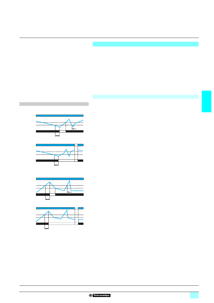
3/35
3
Operation
3
Zelio Control
-
modular measurement
and control relays
3
Single-phase and d.c. voltage control relays
RM17 UAS and RM17 UBE
Operating principle
Voltage control relays RM17 UAS and RM17 UBE monitor:
1 The voltages of single-phase and d.c. supplies.
These products monitor their own supply voltage.
RM17 UAS
33 relays give the user a choice of two operating modes:
1 Overvoltage or undervoltage,
1 Fault memory selected or not.
An adjustable time delay, on crossing the thresholds, provides immunity to
transients, so preventing spurious triggering of the output relay.
Fault signalling is by LED.
Overvoltage or undervoltage control relays: RM17 UAS14, UAS15 and UAS16
The operating mode is fixed by the user:
A switch allows selection between the following modes:
1 Undervoltage with or without memory
1 Overvoltage with or without memory.
The position of the switch, and therefore the operating mode, is read by the product
on energisation.
If the switch is set to an unacceptable position, the product detects a fault, the output
relay stays open and the LEDs flash to signal the position error.
If the switch position is changed while the device is operating, all the LEDs flash, but
the product continues to operate normally with the function selected at the time of
energisation preceding the change of position.
The LED's return to their normal state if the switch is returned to the original position
selected prior to the last energisation.
The undervoltage or overvoltage threshold value is set by means of a graduated
potentiometer clearly indicating the Un to be monitored.
The hysteresis is adjusted by means of a potentiometer graduated from 5…20 % of
the threshold setting. The hysteresis value must not exceed the limit values of the
measuring range.
If the voltage controlled exceeds the threshold setting for a time greater than that set
on the front panel (0.1…10 s), the output relay opens and LED R goes out.
As soon as the voltage returns to a value above (or below) the threshold setting
minus (or respectively plus) the hysteresis, the relay instantly closes.
"Memory" mode
If "Memory" mode is selected, the relay opens when crossing of the threshold is
detected and then stays in that position.
The power must be switched off to reset the product.
Function diagrams
1 Function: Undervoltage control.
<
U
2 without memory. No Memory
2 with memory. Memory
11-12/11-14
U
U
Tt
<
Relays
Hysteresis
Supply Un
Threshold
Tt
11-12/11-14
U
U
<
Relays
Hysteresis
Supply Un
Threshold
1 Function: Overvoltage control.
>
U
2 without memory. No Memory
2 with memory. Memory
Tt: time delay after crossing of threshold
11-12/11-14
U
>
Tt
U
Relays
Threshold
Supply Un
Hysteresis
11-12/11-14
U
>
U
Tt
Relays
Threshold
Supply Un
Hysteresis
Presentation, description :
page 3/34
Characteristics:
pages 3/37 and 3/38
References:
page 3/38
Dimensions, schemes :
page 3/39
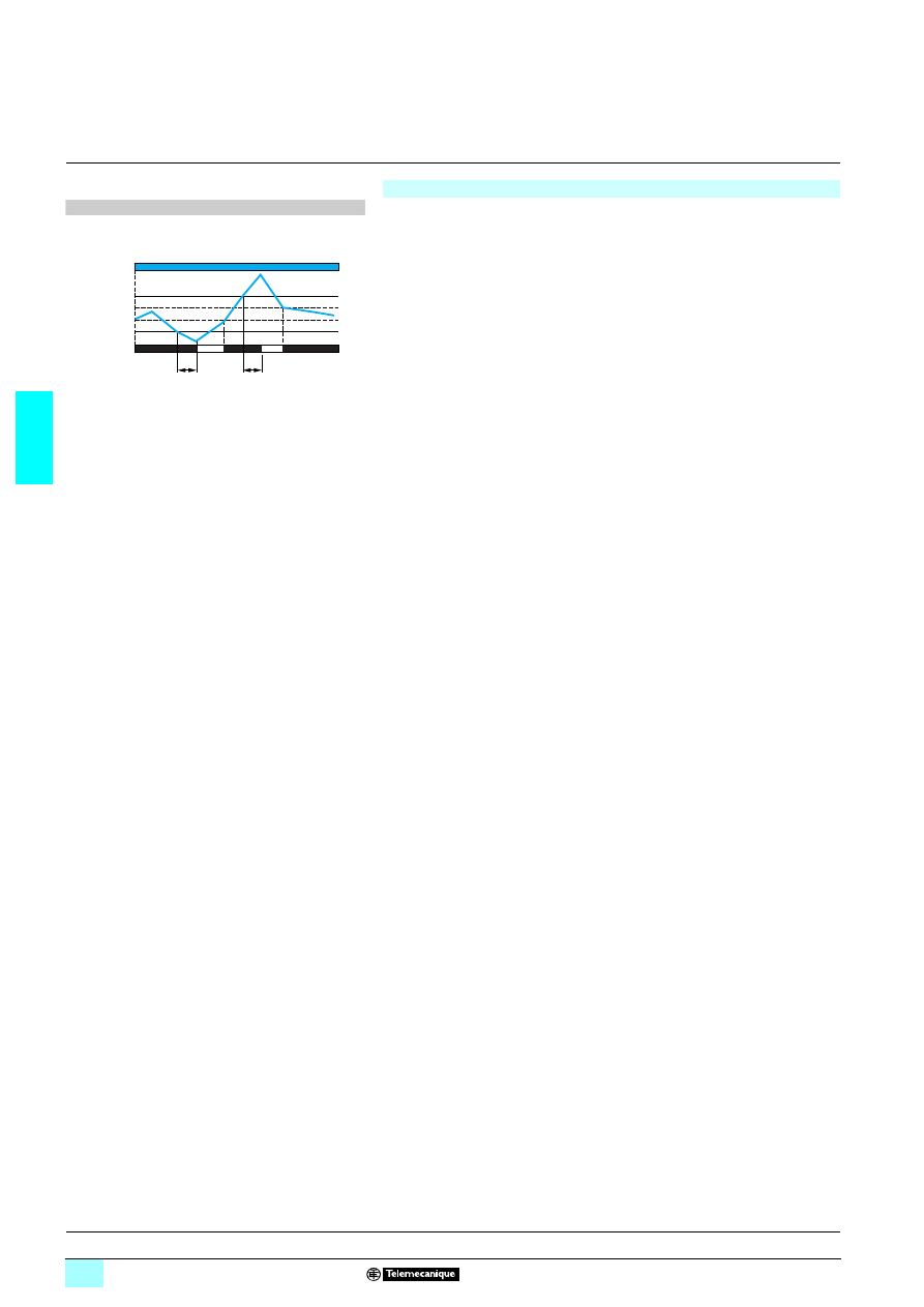
3/36
3
Operation
(continued)
3
Zelio Control
-
modular measurement
and control relays
3
Single-phase and d.c. voltage control relays
RM17 UAS and RM17 UBE
Overvoltage and undervoltage control relays: RM17 UBE15 and UBE16
Relays RM17 UBE operate in window mode: they check that the voltage controlled
stays between a minimum threshold and a maximum threshold.
The undervoltage or overvoltage threshold values are set by means of two graduated
potentiometers clearly indicating the Un to be monitored.
The hysteresis is fixed at: 3 % of the threshold setting.
If the voltage controlled exceeds the high threshold setting, or falls below the low
threshold setting for a time greater than that set on the front panel (0.1…10 s), the
output relay opens and LED R goes out. During the time delay, this LED flashes.
As soon as the voltage falls below the high threshold setting value minus the
hysteresis, or rises above the low threshold setting value plus the hysteresis, the
relay instantly closes.
On energisation of the device with a fault measured, the relay stays open.
Function diagrams
1 Function: Control of overvoltage and undervoltage
in window mode.
<
U
<
Tt: time delay after crossing of threshold
11-12/11-14
Tt
Tt
U
U
>
U
<
Relays
Hysteresis
Supply Un
Threshold
Hysteresis
Threshold
Presentation, description :
page 3/34
Characteristics:
pages 3/37 and 3/38
References:
page 3/38
Dimensions, schemes :
page 3/39
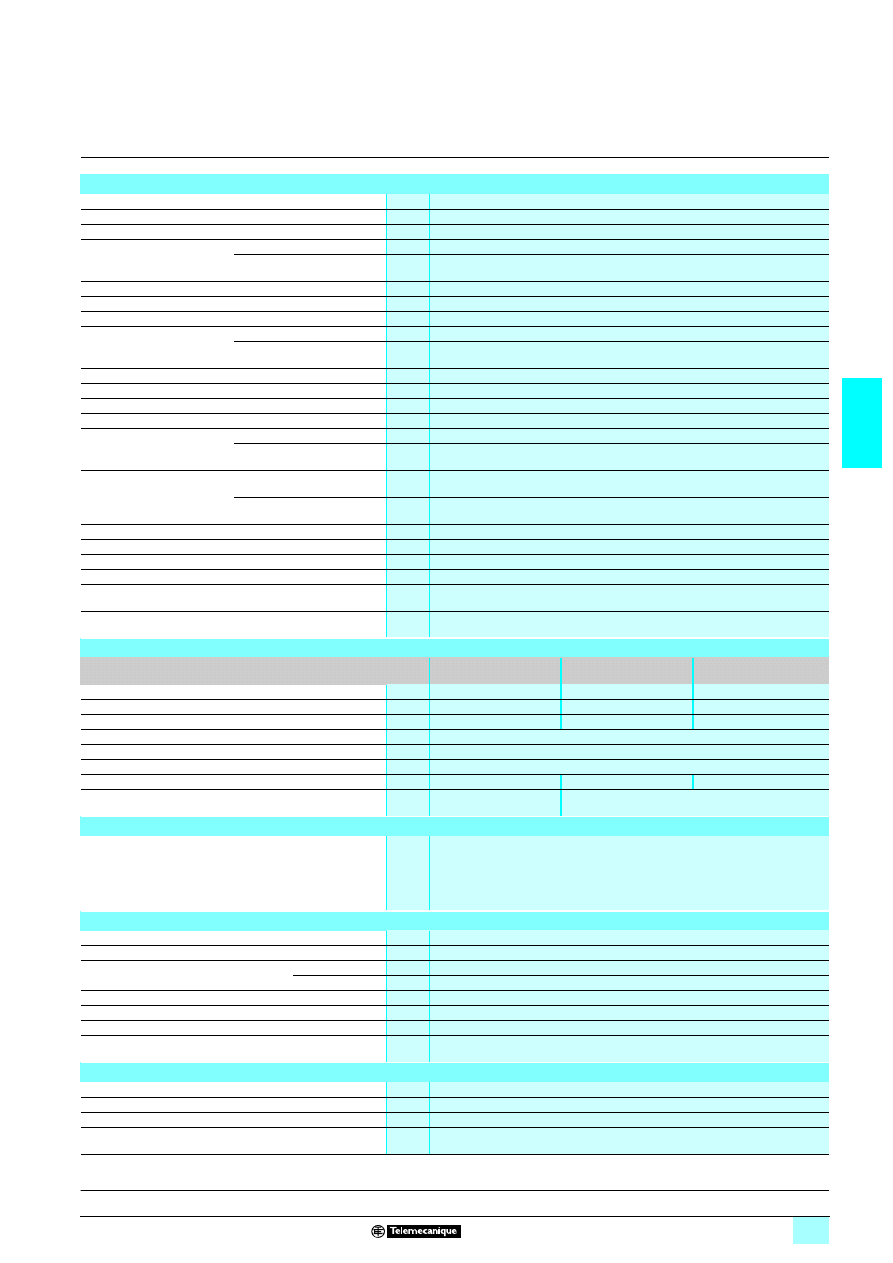
3/37
3
Characteristics
3
Zelio Control
-
modular measurement
and control relays
3
Single-phase and d.c. voltage control relays
RM17 UAS and RM17 UBE
Environment characteristics
Conforming to standards
NF EN 60255-6 and IEC 60255-6
Product certifications
Pending
UL, CSA, GL, C-Tick, GOST
Marking
1
1
1
1: 73/23/EEC and EMC 89/336/EEC
Ambient air temperature
around the device
Storage
°C
- 40…+ 70
Operation
°C
- 20…+ 50
Permissible relative humidity Conforming to IEC 60068-2-30
2 x 24 hours…+ 95 % RH at + 55 °C (without condensation)
Vibration resistance
Conforming to IEC 60068-2-6
0.035 mm from 10…150 Hz
Shock resistance
Conforming to IEC 60068-2-6
5 gn
Degree of protection
Conforming to IEC 60529
Casing
IP 30
Terminals
IP 20
Degree of pollution
Conforming to IEC 60664-1
3
Overvoltage category
Conforming to IEC 60664-1
III
Insulation resistance
Conforming to 60664-1/60255-5
> 500 M
Ω,
2 500 V
Rated insulation voltage
Conforming to IEC 60664-1
V
250 or 400
Insulation test voltage
Conforming to
IEC 60664-1/60255-5
Dielectric test
kV
2,
1 50 Hz, 1 min.
Shock wave
kV
4 (1.2/50 µs)
Connection
Maximum c.s.a.
Conforming to IEC 60947-1
Solid cable without cable end
mm
2
1 conductor: 0.5…4 (AWG 20…AWG 11)
2 conductors: 0.5…2.5 (AWG 20…AWG 14)
Flexible cable with cable end
mm
2
1 conductor: 0.2…2.5 (AWG 24…AWG 12)
2 conductors: 0.2…1.5 (AWG 24…AWG 16)
Tightening torque
Conforming to IEC 60947-1
0.6…1 N.m / 5.3…8.8 Lbf.In
Housing material
Self-extinguishing plastic
Power ON indicator
Green LED
Relay state indicator
Yellow LED (flashes during the time delay on crossing the threshold)
Mounting position
without derating
In relation to normal
vertical mounting plane
Any position
Mounting
Conforming to IEC/EN 60715
On 35 mm
3 rail
Supply characteristics
Relay type
RM17 UAS14
RM17 UAS16
RM17 UBE16
RM17 UAS15
RM17 UBE15
Rated supply voltage Un
V
2 12
1/2 24…48
1/2 110…240
Operating range
V
2 7…20
1/2 15…100
1/2 50… 270
Setting range
V
2 9…15
1/2 20…80
1/2 65…260
Polarity on d.c. supply
Yes
Frequency
Of the power supply circuit
Hz
50/60 Hz ± 10 %
Galvanic isolation, supply/measurement
No
Maximum power consumption at Un
2 1 W
2 1.6 W, 1 3.9 VA
2 1 W, 1 3 VA
Immunity to microbreaks
ms
20 at 12 V
20
Immunity to electromagnetic interference
Electromagnetic compatibility
Immunity NF EN 61000-6-2 / IEC 61000-6-2
Emission NF EN 61000-6-4
NF EN 61000-6-3
IEC 61000-6-4
IEC 61000-6-3
Input and measurement circuit characteristics
Frequency of the measured signal
Hz
50…60 ± 10 %
Maximum measuring cycle
ms
250/measurement as true rms value
Adjustable hysteresis or fixed hysteresis RM17 UAS
77
5…20 % of the threshold setting
RM17 UBE
77
3 % of the fixed threshold setting
Setting accuracy
10 % of the full scale value
Repeat accuracy (with constant parameters)
± 0.5 %
Measurement error with voltage variation
< 1 % over the whole range
Measurement error with temperature variation
0.2 %/ °C
Time delay characteristics
Time delay on crossing the threshold
s
0.1…10, 0 + 10 %
Repeat accuracy (with constant parameters)
± 1 %
Reset time
s
1.5
Delay on pick-up
ms
1 500 / 2 1000
Presentation, description :
page 3/34
Operation:
pages 3/35 and 3/36
References:
page 3/38
Dimensions, schemes :
page 3/39
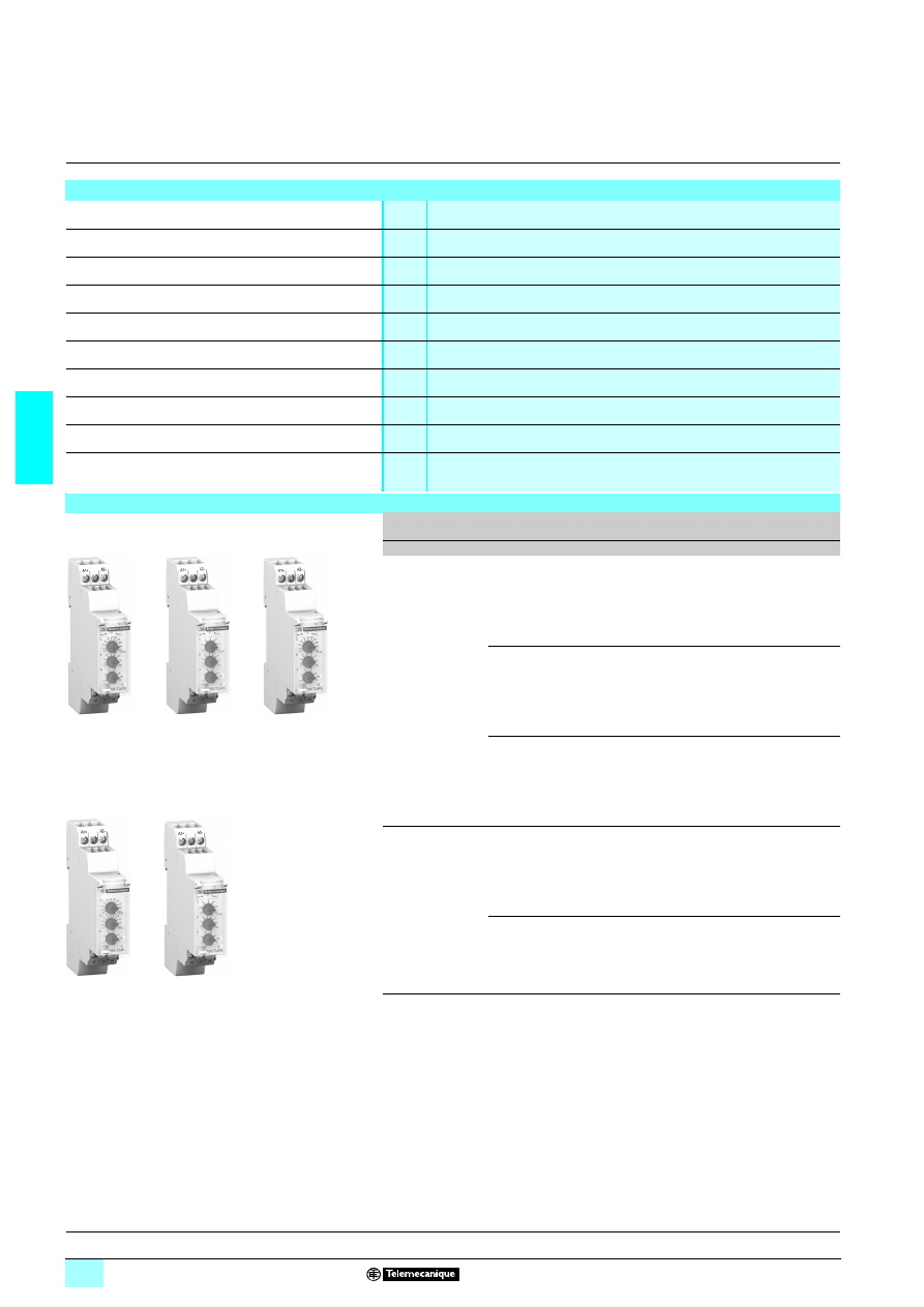
3/38
3
Characteristics
(continued)
,
references
3
Zelio Control
-
modular measurement
and control relays
3
Single-phase and d.c. voltage control relays
RM17 UAS and RM17 UBE
Output characteristics
Type of output
1 C/O contact
Contact type
Cadmium-free
Maximum switching voltage
V
1/2 250
Rated breaking capacity
VA
1250
Minimum breaking current
mA
10/
2 5 V
Maximum breaking current
A
1/2 5
Electrical durability
1 x 10
5
operating cycles
Mechanical durability
30 x 10
6
operating cycles
Maximum operating rate
360 operations/hour under full load
Utilisation categories
Conforming to IEC 60947-5-1
AC-12, AC-13, AC-14, AC-15, DC-12, DC-13, DC-14
References
Function
Ranges
controlled
Nominal
voltage
Out-
put
Reference
Weight
V
V
kg
1 Overvoltage
or undervoltage
2 9…15
2 12
1 C/O
5 A
RM17 UAS14
0.080
1/2 20…80
1/2 24…48
1 C/O
5 A
RM17 UAS16
0.080
1/2 65…260 1/2 110…240 1 C/O
5 A
RM17 UAS15
0.080
1 Overvoltage
and undervoltage
in window mode
1/2 20…80
1/2 24…48
1 C/O
5 A
RM17 UBE16
0.080
1/2 65…260 1/2 110…240 1 C/O
5 A
RM17 UBE15
0.080
RM17 UAS14
RM17 UAS16
RM17 UAS15
10
64
42
10
64
41
10
64
42
RM17 UBE16
RM17 UBE15
10
64
44
10
64
43
Presentation, description :
page 3/34
Operation:
pages 3/35 and 3/36
Characteristics:
pages 3/37 and 3/38
Dimensions, schemes :
page 3/39
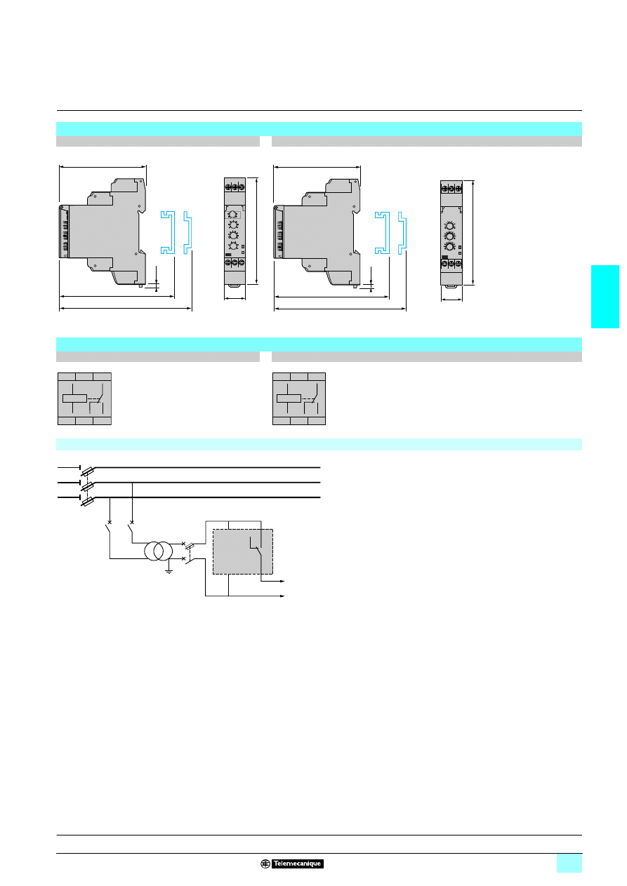
3/39
3
Dimensions,
schemes
3
Zelio Control
-
modular measurement
and control relays
3
Single-phase and d.c. voltage control relays
RM17 UAS and RM17 UBE
Dimensions
RM17 UAS
22
22
22
22
RM17 UBE
22
22
22
22
mm/In.
Schemes
RM17 UAS14
RM17 UAS16, RM17 UAS15, RM17 UBE
22
22
22
22
Application scheme
17,5
0.69
90/
3.54
A1
A2
12 11 14
R
Un
72/
2.83
2,8
0.11
76/
2.99
72,5/
2.85
72/
2.83
2,8
0.11
76/
2.99
72,5/
2.85
17,5
0.69
90/
3.54
A1
A2
12 11 14
A1 –
A2 +
11
12
14
A1
A2
11
12
14
R
11
12
14
A1
A2
11
12
14
R
A1 +
A2 –
11
14
12
Q2
1
2
Q2
1
2
Q1
1/L1
2
3/L2
4
5/L3
6
Q4
RM17 U
A2
A1
To sensitive loads
Presentation, description :
page 3/34
Operation:
pages 3/35 and 3/36
Characteristics:
pages 3/37 and 3/38
References:
page 3/38
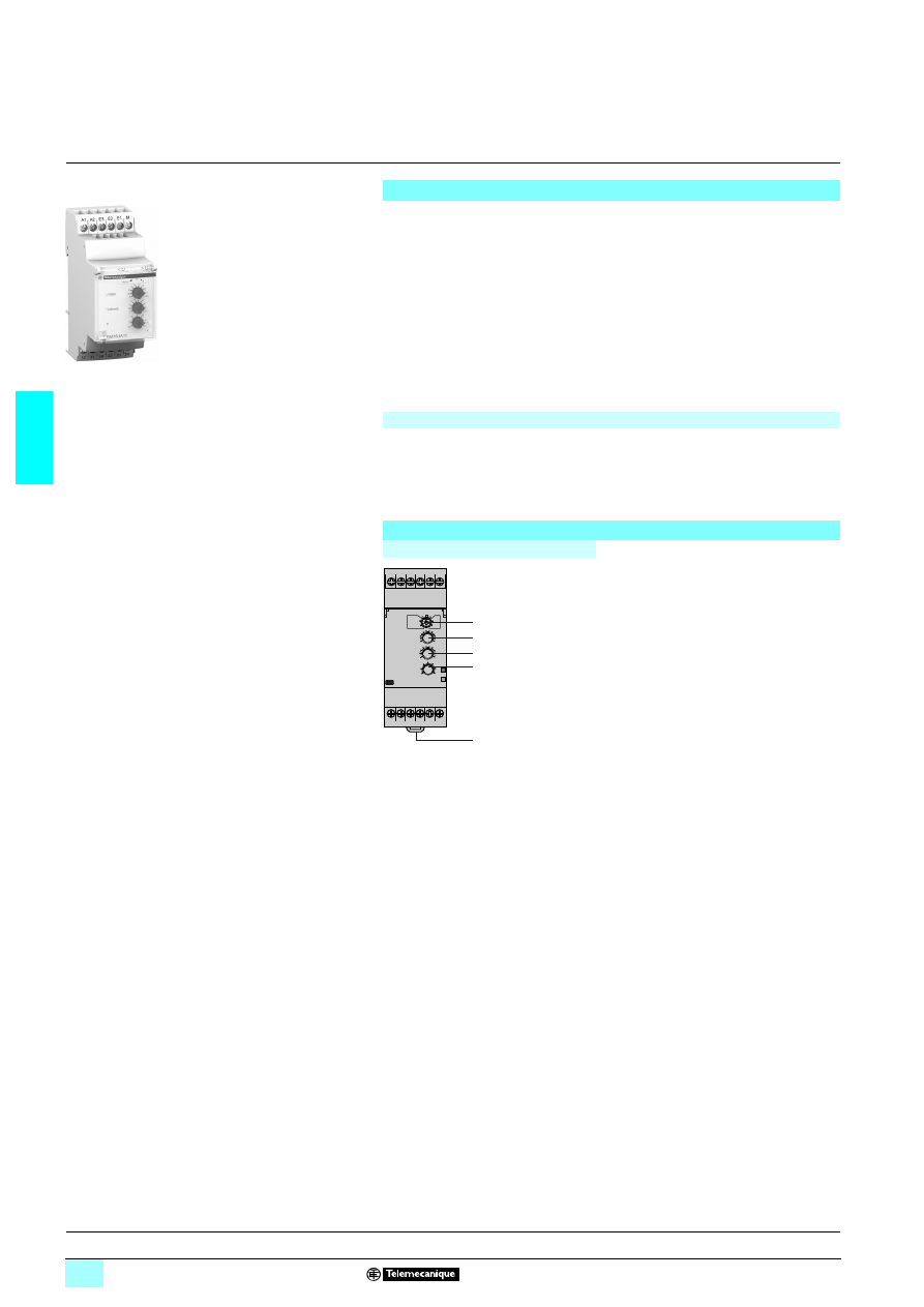
3/40
3
Presentation,
description
3
Zelio Control
-
modular measurement
and control relays
3
Multifunction voltage control relays
RM35 UA
Presentation
Multifunction voltage control relays RM35 UA1
3MW monitor both a.c. and d.c.
voltages.
1 Automatic 7 or 4 recognition,
1 Measurement ranges from 0.05 V to 600 V,
1 Selection between overvoltage and undervoltage,
1 Measurement as true rms value,
1 Selectable memory function.
Settings are protected by a sealable cover.
Control status is indicated by a LED.
The relays are designed for clip-on mounting on
5 rail
Applications
1 d.c. motor overspeed control,
1 Battery monitoring,
1 Monitoring of a.c. or d.c. supplies,
1 Speed monitoring (with tacho-generator).
Description
RM35 UA11MW, UA12MW, UA13MW
1
Configuration: selection of operating
mode
<
U /
>
U, (with or without memory)
Memory - No Memory
2
Voltage threshold setting potentiometer.
U Value
3
Hysteresis adjustment potentiometer. H
4
Time delay setting potentiometer. Tt
5
Spring for clip-on mounting on 35 mm
5 rail.
Un Green LED: indicates that supply to the relay is on.
R
Yellow LED: indicates relay output state.
RM35 UA1
1MW
10
56
78
5
A1
12
22 21 24
14
11
A2 E3 E2 E1 M
Un
R
< U
> U
1
2
3
4
Operation:
page 3/41
Characteristics:
page 3/42
References, dimensions :
page 3/43
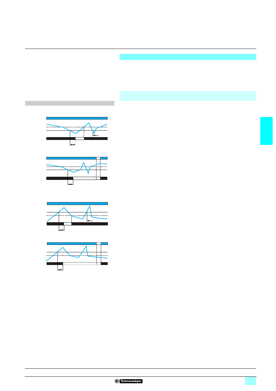
3/41
3
Operation
3
Zelio Control
-
modular measurement
and control relays
3
Multifunction voltage control relays
RM35 UA
Operating principle
Control relays RM35 UA1
3MW are designed for the monitoring of a.c. or d.c.
voltages.
They automatically recognise the form of the
7 or 4 (50 or 60 Hz) signal.
Fault signalling is by LED.
Overvoltage and undervoltage control relays: RM35 UA11MW, UA12MW and
UA13MW
1 The operating mode is fixed by the user :
A switch allows selection between the following modes:
2 Undervoltage with or without memory,
2 Overvoltage with or without memory.
The position of the switch, and therefore the operating mode, is read by the product
on energisation.
If the switch is set to an unacceptable position, the product detects a fault, the output
relay stays open and the LEDs flash to signal the position error.
If the switch position is changed while the device is operating, all the LEDs flash, but
the product continues to operate normally with the function selected at the time of
energisation preceding the change of position.
The LED's return to their normal state if the switch is returned to the original position
selected prior to the last energisation.
The undervoltage or overvoltage threshold value is set by means of a potentiometer
graduated as a percentage of the scale value of Un to be monitored.
The hysteresis is adjusted by means of a potentiometer graduated from 5…50 % of
the threshold setting.
The hysteresis value must not exceed the limit values of the measuring range.
In overvoltage mode, if the voltage controlled exceeds the threshold setting for a
time greater than that set on the front panel (0.3…30 s), the output relay opens and
LED R goes out. During the time delay, this LED flashes.
As soon as the voltage drops below the value of the threshold setting, minus the
hysteresis, the relay instantly closes.
In undervoltage mode, if the voltage controlled falls below the threshold setting for
a time greater than that set on the front panel (0.3…30 s), the output relay opens
and LED R goes out. During the time delay, this LED flashes.
As soon as the voltage rises above the value of the threshold setting, plus the
hysteresis, the relay instantly closes.
1 "Memory" mode :
If "Memory" mode is selected, the relay opens when crossing of the threshold is
detected and then stays in that position.
The power must be switched off to reset the product.
Function diagrams
1 Function: Undervoltage control.
<
U
2 without memory. No Memory
2 with memory. Memory
11-12/11-14
21-22/21-24
U
U
Tt
<
Relays
Hysteresis
Supply Un
Threshold
11-12/11-14
21-22/21-24
U
Tt
U
<
Relays
Hysteresis
Supply Un
Threshold
1 Function: Overvoltage control.
>
U
2 without memory. No Memory
2 with memory. Memory
Tt: time delay after crossing of threshold (adjustable on front
panel)
11-12/11-14
21-22/21-24
U
>
Tt
U
Relays
Hysteresis
Supply Un
Threshold
11-12/11-14
21-22/21-24
U
>
U
Tt
Relays
Hysteresis
Supply Un
Threshold
Presentation, description :
page 3/40
Characteristics:
page 3/42
References, dimensions :
page 3/43
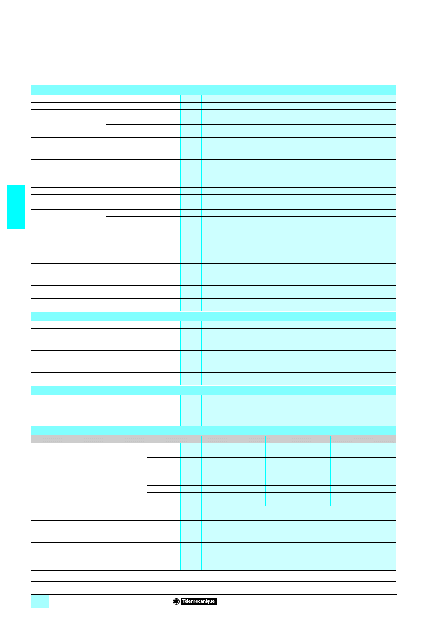
3/42
3
Characteristics
3
Zelio Control
-
modular measurement
and control relays
3
Multifunction voltage control relays
RM35 UA
Environment characteristics
Conforming to standards
NF EN 60255-6 and IEC 60255-6
Product certifications
Pending
UL, CSA, GL, C-Tick, GOST
Marking
6: 73/23/EEC and EMC 89/336/EEC
Ambient air temperature
around the device
Storage
°C
- 40…+ 70
Operation
°C
- 20…+ 50
Permissible relative humidity Conforming to IEC 60068-2-30
2 x 24 hours…+ 95 % RH at + 55 °C (without condensation)
Vibration resistance
Conforming to IEC 60068-2-6
0.035 mm from 10…150 Hz
Shock resistance
Conforming to IEC 60068-2-6
5 gn
Degree of protection
Conforming to IEC 60529
Casing
IP 30
Terminals
IP 20
Degree of pollution
Conforming to IEC 60664-1
3
Overvoltage category
Conforming to IEC 60664-1
III
Insulation resistance
Conforming to 60664-1/60255-5
> 500 M
Ω,
2 500 V
Rated insulation voltage
Conforming to IEC 60664-1
V
250 or greater (measured at 600 V)
Insulation test voltage
Conforming to
IEC 60664-1/60255-5
Dielectric test
kV
2,
1 50 Hz, 1 min.
Shock wave
kV
4 (1.2/50 µs)
Connection
Maximum c.s.a.
Conforming to IEC 60947-1
Solid cable without cable end
mm
2
1 conductor: 0.5…4 (AWG 20…AWG 11)
2 conductors: 0.5…2.5 (AWG 20…AWG 14)
Flexible cable with cable end
mm
2
1 conductor: 0.2…2.5 (AWG 24…AWG 12)
2 conductors: 0.2…1.5 (AWG 24…AWG 16)
Tightening torque
Conforming to IEC 60947-1
0.6…1 N.m / 5.3…8.8 Lbf.In
Housing material
Self-extinguishing plastic
Power ON indicator
Green LED
Relay state indicator
Yellow LED
Mounting position
without derating
In relation to normal
vertical mounting plane
Any position
Mounting
Conforming to IEC/EN 60715
On 35 mm
3 rail
Supply characteristics
Rated supply voltage Un
V
1/2 24…240
Operating range
V
1/2 20.4… 264
Polarity on d.c. supply
No
Voltage limits
Of the power supply circuit
- 15 %, + 10 %
Frequency
Of the power supply circuit
50/60 Hz ± 10 %
Galvanic isolation, supply/measurement
Yes
Maximum power consumption
143.5 VA, 240.6 W
Immunity to microbreaks
ms
10
Immunity to electromagnetic interference
Electromagnetic compatibility
Immunity NF EN 61000-6-2 / IEC 61000-6-2
Emission NF EN 61000-6-4
NF EN 61000-6-3
IEC 61000-6-4
IEC 61000-6-3
Input and measurement circuit characteristics
Relay type
RM35 UA11MW
RM35 UA12MW
RM35 UA13MW
Measurement range
V
0.05…5
1…100
15…600
Sub-measurement range
E1-M
V
0.05…0.5
1…10
15…150
E2-M
V
0.3…3
5…50
30…300
E3-M
V
0.5…5
10…100
60…600
Input resistance
E1-M
k
Ω
5
22
150
E2-M
k
Ω
30
110
300
E3-M
k
Ω
50
220
600
Frequency of the measured signal
Hz
40…70 ± 10 %
Maximum measuring cycle
ms
30/measurement as true rms value
Threshold setting
10…100 % of the range
Adjustable hysteresis or fixed hysteresis
5…50 % of the threshold setting
Setting accuracy
10 % of the full scale value
Repeat accuracy (with constant parameters)
± 0.5 %
Measurement error with voltage variation
< 1 % / V over the whole range
Measurement error with temperature variation
± 0.05 % / °C
Presentation, description :
page 3/40
Operation:
page 3/41
References, dimensions :
page 3/43
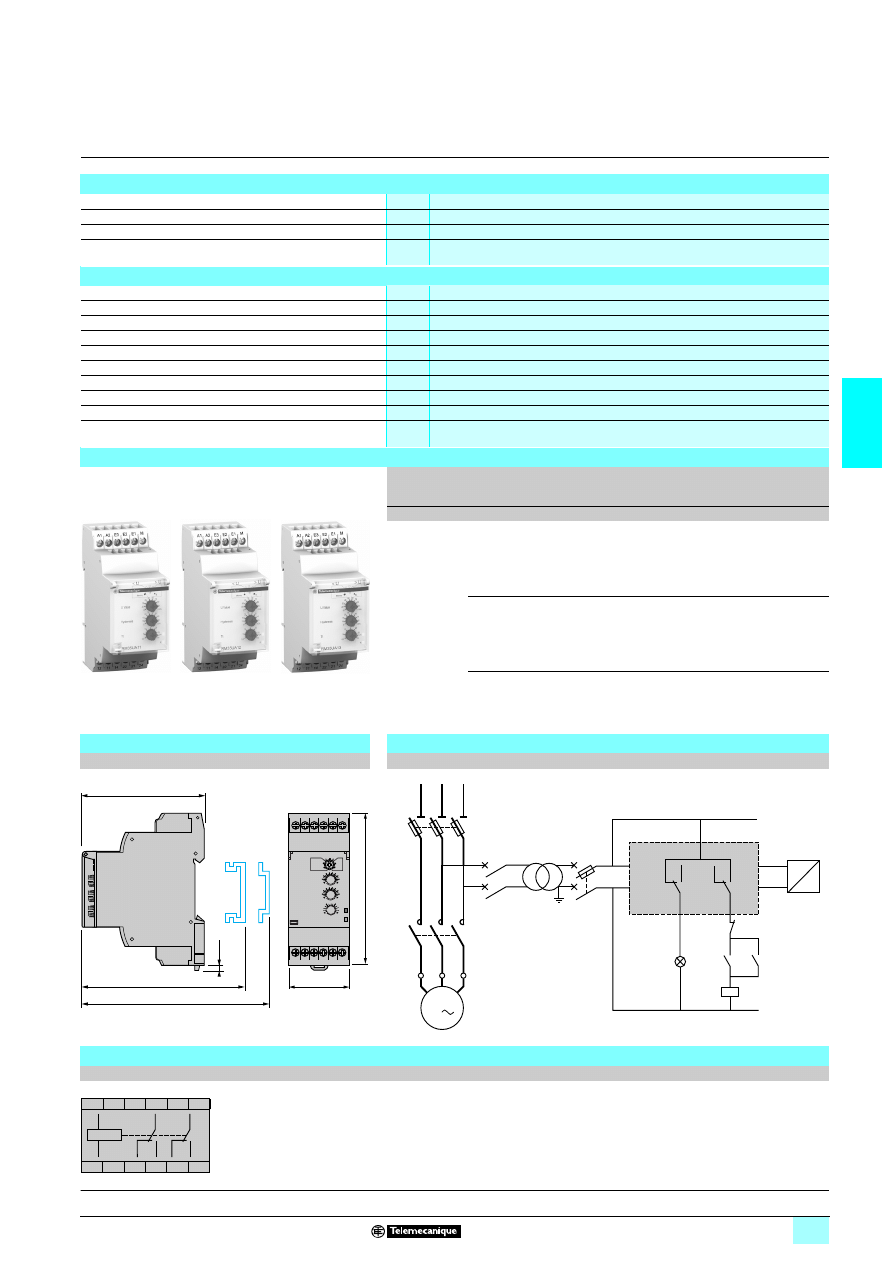
3/43
3
Characteristics
(continued)
references,
dimensions,
schemes
3
Zelio Control
-
modular measurement
and control relays
3
Multifunction voltage control relays
RM35 UA
Time delay characteristics
Time delay on crossing the threshold Tt
s
0.3…30, 0 + 10 %
Repeat accuracy (with constant parameters)
± 2 %
Reset time
s
1.5
Delay on pick-up
ms
600
Output characteristics
Type of output
2 C/O contacts
Contact type
Cadmium-free
Maximum switching voltage
V
1/2 250
Rated breaking capacity
VA
1250
Minimum breaking current
mA
10/
2 5 V
Maximum breaking current
A
1/2 5
Electrical durability
1 x 10
5
operating cycles
Mechanical durability
30 x 10
6
operating cycles
Maximum operating rate
360 operations/hour under full load
Utilisation categories
Conforming to IEC 60947-5-1
AC-12, AC-13, AC-14, AC-15, DC-12, DC-13, DC-14
References
Function
Range
controlled
Supply
voltage
Output
Reference
Weight
V
V
kg
1 Over-
voltage or
undervoltage
0.05…5
1/2 24…240 2 C/O
5 A
RM35 UA11MW
0.130
1…100
1/2 24…240 2 C/O
5 A
RM35 UA12MW
0.130
15…600
1/2 24…240 2 C/O
5 A
RM35 UA13MW
0.130
Dimensions
Application scheme
RM35 UA1
2222MW
Example: overspeed monitoring (undervoltage function)
mm/In.
Scheme
RM35 UA1
2222MW
RM35 UA11MW
10
56
78
RM35 UA12MW
10
56
79
RM35 UA13MW
10
56
80
90/
3.54
72/
2.83
2,8
0.11
76/
2.99
72,5/
2.85
35/
1.38
A1
12
22 21 24
14
11
A2 E3 E2 E1 M
11
14
12
21
24
22
KM1
KM1
KM1
1
2
3
1
1
1
2
2
4
5
6
U1
W1
V1
M1
3
A1
A2
E2
M
RM35 UA12MW
N
Q1
1/L1
2
3/L2
4
5/L3
6
Q2
Q3
Q4
2
U
V
Overspeed
Start
Overspeed
Tacho-
generator
Stop
A1
A2
E3
E2
E1
M
12
11
14
22
21
24
A1
A2
11
12
14
21
22
24
R
Presentation, description :
page 3/40
Operation:
page 3/41
Characteristics:
page 3/42
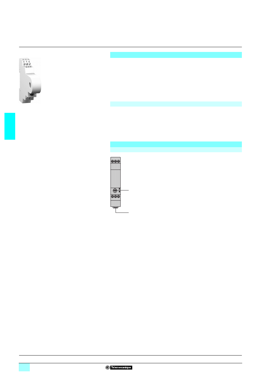
3/44
3
Presentation,
description
3
Zelio Control
-
modular measurement
and control relays
3
Current control relays
RM17 JC
Presentation
The control relay RM17 JC00MW is designed to monitor a.c. currents.
1 Integrated current transformer,
1 Measurement range 2…20 A,
1 Choice of action on the output relay.
Control status is indicated by a LED.
The relay is designed for clip-on mounting on
5 rail
Applications
1 Monitoring of load state of motors and generators,
1 Monitoring of current drawn by a 3-phase motor,
1 Monitoring of heating or lighting circuits,
1 Monitoring of pump draining (undercurrent),
1 Monitoring of overtorque (crushers),
1 Monitoring of electromagnetic brakes or clutches.
Description
RM17 JC00MW
1
Overcurrent setting potentiometer.
2
Spring for clip-on mounting on 35 mm
5 rail.
Un Green LED: indicates that supply to the relay is on.
R
Yellow LED: indicates relay output state.
RM17 JC00MW
10
64
45
A1 Y1 A2
12 11 14
Un
R
1
2
Operation:
page 3/45
Characteristics:
page 3/46
References, dimensions :
page 3/47
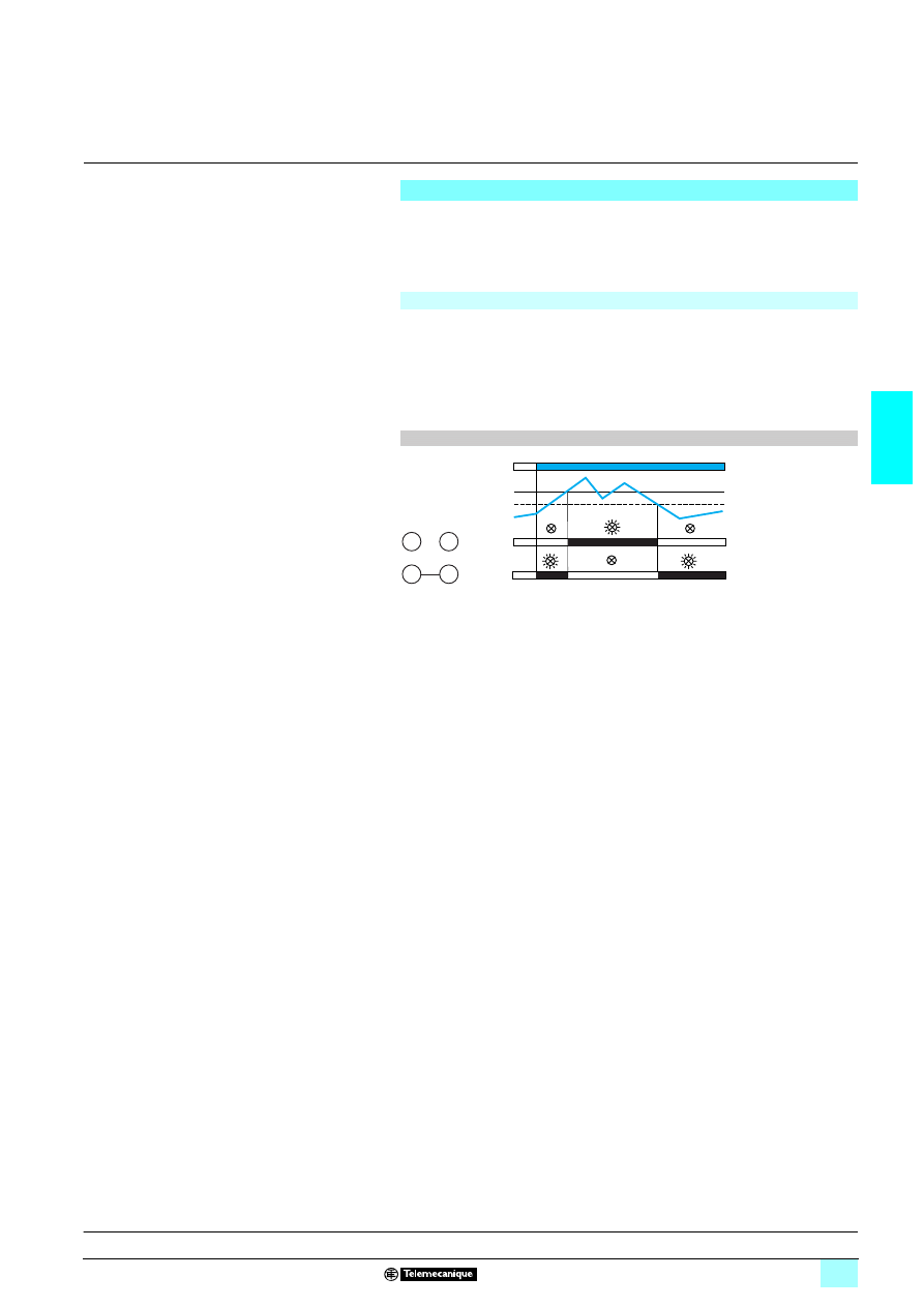
3/45
3
Operation
3
Zelio Control
-
modular measurement
and control relays
3
Current control relays
RM17 JC
Operating principle
1 Control relay RM17 JC00MW is designed to monitor overcurrent.
1 It is equipped with an integrated current transformer
Fault signalling is by LED.
Current control relay
Relay RM17 JC00MW controls overcurrent.
The relay closes when the current exceeds the threshold setting on the front panel
and opens when it drops below the threshold minus the hysteresis.
When terminal Y1 is linked to A1 (+), the output is reversed. The relay opens when
the current exceeds the threshold setting on the front panel and closes again when
it drops below the hystereris value.
Function diagram
I>
I
Y1
A1
Y1
A1
11-12
11-14
11-12
11-14
Relays
Relays
Hysteresis
Supply Un
Presentation, description :
page 3/44
Characteristics:
page 3/46
References, dimensions :
page 3/47
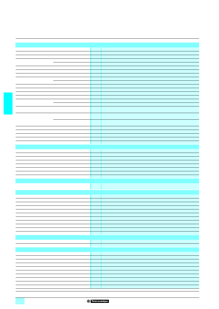
3/46
3
Characteristics
3
Zelio Control
-
modular measurement
and control relays
3
Current control relays
RM17 JC
Environment characteristics
Conforming to standards
NF EN 60255-6 and IEC 60255-6
Product certifications
Pending
UL, CSA, GL, C-Tick, GOST
Marking
1
1
1
1: 73/23/EEC and EMC 89/336/EEC
Ambient air temperature
around the device
Storage
°C
- 40…+ 70
Operation
°C
- 20…+ 50
Permissible relative humidity Conforming to IEC 60068-2-30
2 x 24 hours…+ 95 % RH at + 55 °C (without condensation)
Vibration resistance
Conforming to IEC 60068-2-6
0.035 mm from 10…150 Hz
Shock resistance
Conforming to IEC 60068-2-6
5 gn
Degree of protection
Conforming to IEC 60529
Casing
IP 30
Terminals
IP 20
Degree of pollution
Conforming to IEC 60664-1
3
Overvoltage category
Conforming to IEC 60664-1
III
Insulation resistance
Conforming to 60664-1/60255-5
> 500 M
Ω,
2 500 V
Rated insulation voltage
Conforming to IEC 60664-1
V
400
Insulation test voltage
Dielectric test
kV
2,
1 50 Hz, 1 min.
Shock wave
kV
4
Mounting position
without derating
In relation to normal
vertical mounting plane
Any position
Connection
Maximum c.s.a.
Conforming to IEC3 60947-1
Solid cable without cable end
mm
2
1 conductor: 0.5…4 (AWG 20…AWG 11)
2 conductors: 0.5…2.5 (AWG 20…AWG 14)
Flexible cable with cable end
mm
2
1 conductor: 0.2…2.5 (AWG 24…AWG 12)
2 conductors: 0.2…1.5 (AWG 24…AWG 16)
Tightening torque
Conforming to IEC 60947-1
0.6…1 N.m / 5.3…8.8 Lbf.In
Housing material
Self-extinguishing plastic
Power ON indicator
Green LED
Relay state indicator
Yellow LED
Mounting
Conforming to IEC/EN 60715
On 35 mm
3 rail
Supply characteristics
Rated supply voltage Un
V
1/2 24…240
Operating range
V
1/2 20.4…264
Polarity on d.c. supply
Yes
Voltage limits
Of the power supply circuit
- 15 %, + 10 %
Frequency
Of the power supply circuit
Hz
50/60 Hz ± 10 %
Galvanic isolation, supply/measurement
Yes
Maximum power consumption
VA
3 VA, 1 W
Immunity to microbreaks
ms
10
Immunity to electromagnetic interference
Electromagnetic compatibility
Immunity NF EN 61000-6-2 / IEC 61000-6-2
Emission NF EN 61000-6-4, NF EN 61000-6-3, IEC 61000-6-4, IEC 61000-6-3
Input and measurement circuit characteristics
Measurement range
A
2…20
Continuous overload at 25 °C
A
100
Non repetitive overload < 3 s at 25 °C
A
300
Frequency of the measured signal
Hz
40…70 sinusoidal
Maximum measuring cycle
ms
30, measured as true rms value
Adjustment of current threshold
%
10…100 % of the range
Fixed hysteresis
%
15 % of the threshold setting, fixed
Setting accuracy
± 10 % of the full scale value
Repeat accuracy (with constant parameters)
± 0,5 %
Measurement error with voltage variation
< 1 % / V over the whole range
Measurement error with temperature variation
± 0,05 % / °C
Time delay characteristics
Time delay in the event of a fault
ms
< 200
Delay on pick-up
ms
500
Output characteristics
Output type
1 C/O contact
Contact type
Cadmium-free
Nominal current
A
5
Maximum switching voltage
V
1/2 250
Rated breaking capacity
VA
1250
Minimum breaking current
mA
10 /
2 5 V
Electrical durability
1 x 10
5
operating cycles
Mechanical durability
30 x 10
6
operating cycles
Maximum operating rate
360 operations/hour under full load
Utilisation categories
Conforming to IEC 60947-5-1
AC-12, AC-13, AC-14, AC-15, DC-12, DC-13, DC-14
Presentation, description :
page 3/44
Operation:
page 3/45
References, dimensions :
page 3/47
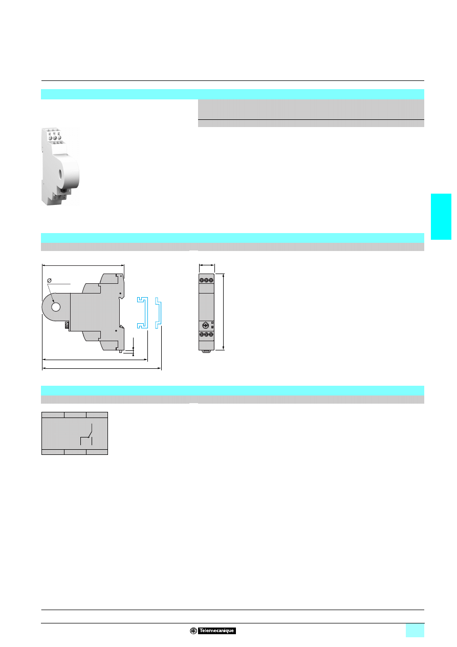
3/47
3
Reference,
dimensions,
scheme
3
Zelio Control
-
modular measurement
and control relays
3
Current control relays
RM17 JC
Reference
Function
Supply
Measure-
ment
range
Output
Reference
Weight
V
A
kg
5 Overcurrent
1/2 24…240 2…20
1 C/O
5 A
RM17 JC00MW
0,110
Dimensions
RM17 JC00MW
mm/In.
Scheme
RM17 JC00MW
RM17 JC00MW
10
64
45
97/
3.82
17,5
0.69
90/
3.54
2,8
0.11
101/
3.98
97,5/
3.84
10/0
.39
12
14
11
11
12
14
A1
A2
Y1
R
I>
Presentation, description :
page 3/44
Operation:
page 3/45
Characteristics:
page 3/46
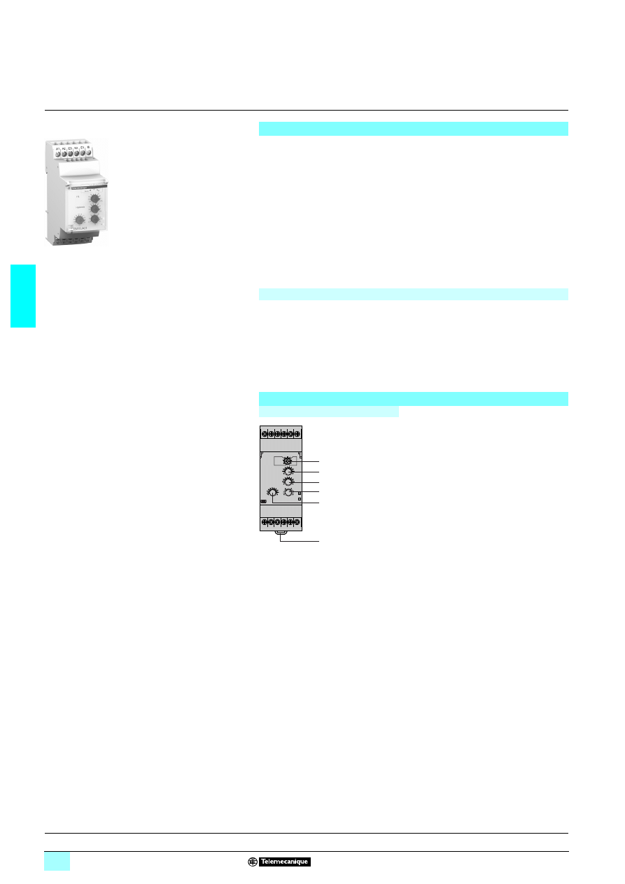
3/48
3
Presentation,
description
3
Zelio Control
-
modular measurement
and control relays
3
Current control relays RM35 JA
Presentation
Multifunction current control relays RM35 JA3
3MW monitor both a.c. and d.c.
currents.
1 Automatic 7 or 4 recognition,
1 Measurement ranges from 2 mA to 15 A,
1 Selection between overcurrent and undercurrent,
1 Measurement as true rms value,
1 Selectable memory function.
Settings are protected by a sealable cover.
Control status is indicated by a LED.
The relays are designed for clip-on mounting on
5 rail
Applications
1 Excitation control of d.c. machines,
1 Control of load state of motors and generators,
1 Control of current drawn by a 3-phase motor,
1 Monitoring of heating or lighting circuits,
1 Control of pump draining (undercurrent),
1 Control of overtorque (crushers),
1 Monitoring of electromagnetic brakes or clutches.
Description
RM35 JA31MW, RM35 JA32MW
1
Configuration: selection of operating mode
<
I /
>
I, (with or without memory)
Memory - No Memory.
2
Current threshold setting potentiometer.
I %
3
Hysteresis adjustment potentiometer.
Hysteresis
4
Time delay adjustment potentiometer. Tt
5
Starting inhibit time delay adjustment
potentiometer. Ti
6
Spring for clip-on mounting on 35 mm
5
rail.
Un Green LED: indicates that supply to the relay is on.
R
Yellow LED: indicates relay output state.
RM35 JA3
1MW
10
56
82
A1
12
22 21 24
14
11
A2 E3 E2 E1 M
< I
> I
Un
R
6
1
2
3
4
5
Operation:
page 3/49
Characteristics:
page 3/50
References, dimensions :
page 3/51
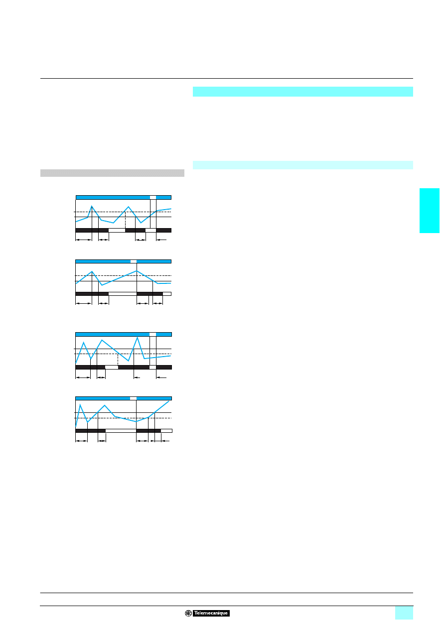
3/49
3
Operation
3
Zelio Control
-
modular measurement
and control relays
3
Current control relays RM35 JA
Operating principle
Control relays RM35 JA3
3MW are designed for the monitor of a.c. or d.c. currents.
They automatically recognise the form of the
7 or 4 (50 or 60 Hz) signal and can
provide direct monitor up to 15 A. Above this value, a current transformer can be
connected.
Fault signalling is by LED.
a.c. or d.c. current control relays: RM35 JA31MW and JA32MW
The operating mode is fixed by the user:
A switch allows selection between the following modes:
1 Undercurrent, with or without memory,
1 Overcurrent, with or without memory.
The position of the switch, and therefore the operating mode, is read by the product
on energisation.
If the switch is set to an unacceptable position, the product detects a fault, the output
relay stays open and the LEDs flash to signal the position error.
If the switch position is changed while the device is operating, all the LEDs flash, but
the product continues to operate normally with the function selected at the time of
energisation preceding the change of position.
The LED's return to their normal state if the switch is returned to the original position
selected prior to the last energisation.
The undercurrent or overcurrent threshold value is set by means of a potentiometer
graduated as a percentage of the scale value of I to be monitored.
The hysteresis is adjusted by means of a potentiometer graduated from 5…50 % of
the threshold setting.
The hysteresis value must not exceed the limit values of the measuring range.
In overcurrent (undercurrent) mode, if the current exceeds (falls below) the threshold
setting for a time greater than that set on the front panel (0.3…30 s), the relays open
and the LED goes out.
As soon as the current returns to below (above) the threshold minus (plus)
hysteresis, the relay instantly closes again.
"Memory" mode:
If "Memory" mode is selected, the relay opens when crossing of the threshold is
detected and then stays in that position.
The power must be switched off to reset the product.
On energisation, an inhibit time delay (1…20 s) makes it possible to inhibit current
peaks (or troughs) on start-up of equipment.
Function diagrams
1 Function: Undercurrent detection.
<
I
2 without memory. No Memory
2 with memory. Memory
2
11-12/11-14
21-22/21-24
Ti
Tt
Tt
Ti
I
I
<
Relays
Hysteresis
Supply Un
Threshold
11-12/11-14
21-22/21-24
Ti
Ti
I
I
<
Tt
Tt
Relays
Hysteresis
Supply Un
Threshold
1 Function: Overcurrent detection.
>
I
2 without memory. No Memory
2 with memory. Memory
Ti: starting inhibit time (adjustable on front panel)
Tt: time delay after crossing of threshold (adjustable on front
panel)
11-12/11-14
21-22/21-24
Tt
Tt
Ti
Ti
I
I
>
Relays
Hysteresis
Supply Un
Threshold
11-12/11-14
21-22/21-24
Ti
Tt
Ti
I
I
>
Tt
Relays
Hysteresis
Supply Un
Threshold
Presentation, description :
page 3/48
Characteristics:
page 3/50
References, dimensions :
page 3/51
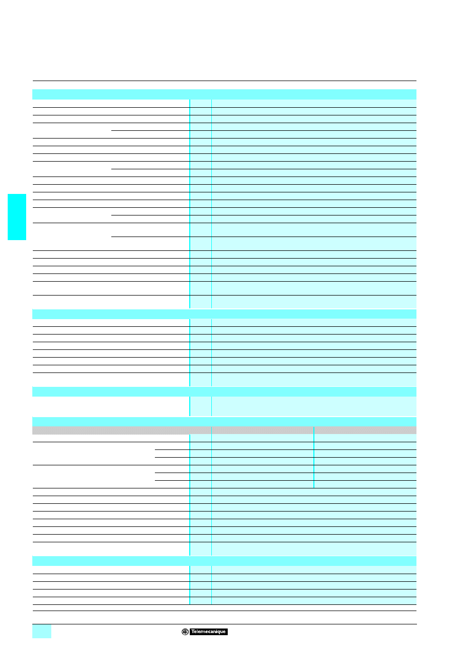
3/50
3
Characteristics
3
Zelio Control
-
modular measurement
and control relays
3
Current control relays RM35 JA
Environment characteristics
Conforming to standards
NF EN 60255-6 and IEC 60255-6
Product certifications
Pending
UL, CSA, GL, C-Tick, GOST
Marking
6: 73/23/EEC and EMC 89/336/EEC
Ambient air temperature
around the device
Storage
°C
- 40…+ 70
Operation
°C
- 20…+ 50
Permissible relative humidity Conforming to IEC 60068-2-30
2 x 24 hours…+ 95 % RH at + 55 °C (without condensation)
Vibration resistance
Conforming to IEC 60068-2-6
0.035 mm from 10…150 Hz
Shock resistance
Conforming to IEC 60068-2-6
5 gn
Degree of protection
Conforming to IEC 60529
Casing
IP 30
Terminals
IP 20
Degree of pollution
Conforming to IEC 60664-1
3
Overvoltage category
Conforming to IEC 60664-1
III
Insulation resistance
Conforming to 60664-1/60255-5
> 500 M
Ω,
2 500 V
Rated insulation voltage
Conforming to IEC 60664-1
V
250
Insulation test voltage
To IEC 60664-1/60255-5
Dielectric test
kV
2,
1 50 Hz, 1 min.
Shock wave
kV
4 (1.2/50 µs)
Connection
Maximum c.s.a.
Conforming to IEC 60947-1
Solid cable without cable end
mm
2
1 conductor: 0.5…4 (AWG 20…AWG 11)
2 conductors: 0.5…2.5 (AWG 20…AWG 14)
Flexible cable with cable end
mm
2
1 conductor: 0.2…2.5 (AWG 24…AWG 12)
2 conductors: 0.2…1.5 (AWG 24…AWG 16)
Tightening torque
Conforming to IEC 60947-1
0.6…1 N.m / 5.3…8.8 Lbf.In
Housing material
Self-extinguishing plastic
Power ON indicator
Green LED
Relay state indicator
Yellow LED
Mounting position
without derating
In relation to normal
vertical mounting plane
Any position
Mounting
Conforming to IEC/EN 60715
On 35 mm
3 rail
Supply characteristics
Rated supply voltage Un
V
1/2 24…240
Operating range
V
1/2 20.4… 264
Polarity on d.c. supply
No
Voltage limits
Of the power supply circuit
- 15 %, + 10 %
Frequency
Of the power supply circuit
50/60 Hz ± 10 %
Galvanic isolation, supply/measurement
Yes
Maximum power consumption
143.5 VA, 240.6 W
Immunity to microbreaks
ms
50
Immunity to electromagnetic interference
Electromagnetic compatibility
Immunity NF EN 61000-6-2 / IEC 61000-6-2
Emission NF EN 61000-6-4, NF EN 61000-6-3, IEC 61000-6-4, IEC 61000-6-3
Measurement circuit and input characteristics
Relay type
RM35 JA31MW
RM35 JA32MW
Measurement range
2…500 mA
0.15…15 A
Sub-measurement range
E1-M
2…20 mA
0.15…1.5 A
E2-M
10…100 mA
0.5…5 A
E3-M
50…500 mA
1.5…15 A
Input resistance
E1-M
Ω
5
0.05
E2-M
Ω
1
0.015
E3-M
Ω
0.2
0.005
Frequency of the measured signal
Hz
40…70 ± 10 %
Maximum measuring cycle
ms
30/measurement as true rms value
Threshold setting
10…100 % of the range
Adjustable hysteresis
5…50 % of the threshold setting
Setting accuracy
± 10 % of the full scale value
Repeat accuracy (with constant parameters)
± 0.5 %
Measurement error with voltage variation
1 % / V over the whole range
Measurement error with temperature variation
0.05 % / °C
Time delay characteristics
Time delay on energisation Ti
s
1…20, 0 + 10 %
Time delay on crossing the threshold Tt
s
0.3…30, 0 + 10 %
Repeat accuracy (with constant parameters)
± 2 %
Reset time
s
1.5
Delay on pick-up
ms
300
Presentation, description :
page 3/48
Operation:
page 3/49
References, dimensions :
page 3/51

3/51
3
Characteristics
(continued),
references,
dimensions,
schemes
3
Zelio Control
-
modular measurement
and control relays
3
Current control relays RM35 JA
Output characteristics
Type of output
2 C/O contacts
Contact type
Cadmium-free
Maximum switching voltage
V
1/2 250
Rated breaking capacity
VA
1250
Minimum breaking current
mA
10/
2 5 V
Maximum breaking current
A
1/2 5
Electrical durability
1 x 10
5
operating cycles
Mechanical durability
30 x 10
6
operating cycles
Maximum operating rate
360 operations/hour under full load
Utilisation categories
Conforming to IEC 60947-5-1
AC-12, AC-13, AC-14, AC-15, DC-12, DC-13, DC-14
References
Function
Range
controlled
Supply
Output
Reference
Weight
V
kg
5 Overcurrent or
undercurrent
2 …500 mA
1/2 24…240 2 C/O
5 A
RM35 JA31MW
0.130
0.15…15 A
1/2 24…240 2 C/O
5 A
RM35 JA32MW
0.130
Dimensions
Scheme
RM35 JA3
2222MW
RM35 JA3
2222MW
mm/In.
Application schemes
Example: detection of jamming on a crusher (overcurrent function)
Current measured
3333 15 A
Current measured > 15 A
RM35 JA31MW
10
56
82
RM35 JA32MW
10
56
83
72/
2.83
2,8
0.11
76/
2.99
72,5/
2.85
90/
3.54
35/
1.38
A1
12
22 21 24
14
11
A2 E3 E2 E1 M
A1
A2
E3
E2
E1
M
12
11
14
22
21
24
A1
A2
11
12
14
21
22
24
R
11
14
12
21
24
22
KM1
KM1
1/L1
2
3/L2
4
5/L3
6
Q1
2/T1
4/T2
6/T3
1
Q2
3
5
KM1
1
2
3
4
5
6
U1
W1
V1
M1
3
E3
M
A1
A2
RM35 JA3
N
Start
OK
Stop
11
14
12
21
24
22
KM1
KM1
1/L1
2
3/L2
4
5/L3
6
Q1
2/T1
4/T2
6/T3
1
Q2
3
5
KM1
1
2
3
4
5
6
U1
W1
V1
M1
3
E3
M
A1
A2
RM35 JA3
N
Start
OK
Stop
Presentation, description :
page 3/48
Operation:
page 3/49
Characteristics:
page 3/50
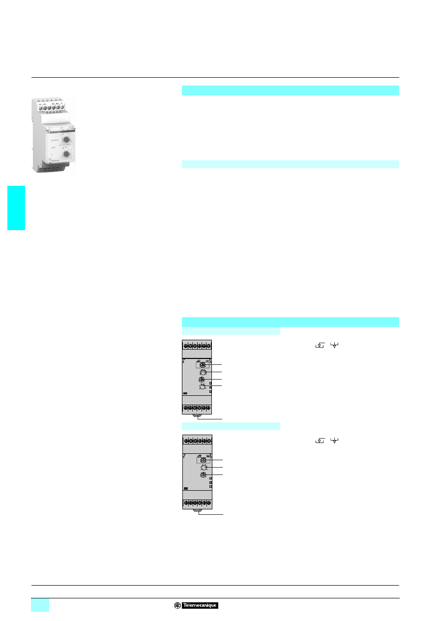
3/52
3
Presentation,
description
3
Zelio Control
-
modular measurement
and control relays
3
Level control relays RM35 L
Presentation
Level control relays RM35 LM33MW and RM35 LV14MW control one or two levels,
with fill or empty function:
1 RM35 LM33MW: control by resistive level probe,
1 RM35 LV14MW: control by discrete sensor.
Settings are protected by a sealable cover.
Control status is indicated by a LED.
The relays are designed for clip-on mounting on
5 rail
Applications
These devices monitor the levels of conductive liquid or non-conductive material.
They control the actuation of pumps or valves to regulate levels. They are also
suitable for protecting submersible pumps against dry running, or protecting tanks
from "overflow". They can also be used to control dosing of liquids in mixing
processes and to protect heating elements in the event of non immersion.
They have a transparent, hinged cover on their front panel to avoid any accidental
alteration of the settings. This cover can be directly sealed.
1 Application examples for RM35 LM33MW:
2 spring, town, industrial and sea water,
2 metallic salt, acid or base solutions,
2 liquid fertilizers,
2 non concentrated alcohol (< 40 %),
2 liquids in the food-processing industry: milk, beer, coffee, etc.
1 Application examples for RM35 LV14MW:
2 chemically pure water,
2 fuels, liquid gasses (inflammable),
2 oil, concentrated alcohol (> 40 %),
2 ethylene, glycol, paraffin, varnish and paints.
Description
RM35 LM33MW
1
Configuration: selection of operating
mode:
/
and of sensitivity
range. LS, St, HS.
2
Sensitivity adjustment potentiometer. %
3
Switch for selecting the number of levels.
4
Time delay adjustment potentiometer. Tt
5
Spring for clip-on mounting on 35 mm
5 rail.
RM35 LV14MW
1
Configuration: selection of operating
mode:
/
and of sensor type
PNP, NPN.
2
Time delay adjustment potentiometer. Tt
3
Switch for selecting the number of levels.
4
Spring for clip-on mounting on 35 mm
5 rail.
Tt Yellow LED: indicates timing status.
Un Green LED: indicates that supply to the relay is on.
R
Yellow LED: indicates relay output state.
RM35 L
111MW
10
56
85
A1
12
22 21 24
11 14
A2
Min Max
C
Tt
Un
R
5
1
2
3
4
12V
A1
12 11 14
A2
12V
Min Max
0V
Tt
Un
R
4
1
2
3
Operation:
pages 3/53 to 3/55
Characteristics:
pages 3/56 and 3/57
References, dimensions :
page 3/57
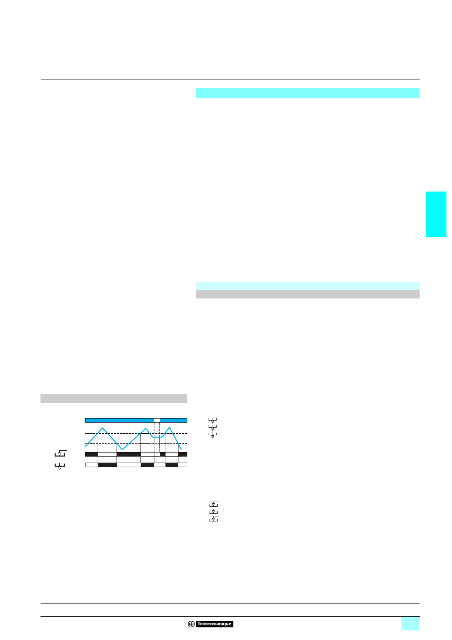
3/53
3
Operation
3
Zelio Control
-
modular measurement
and control relays
3
Level control relays RM35 L
Operating principle
Control relays RM35 LM and RM35 LV are designed to control levels of:
1 Conductive liquid for RM35 LM,
1 Any other material for RM35 LV.
Relay RM35 LM measures the levels by means of resistive probes.
Relay RM35 LM controls the levels of conductive liquids.
The operating principle is based on measurement of the apparent resistance of the
liquid between two submerged probes. When this value is less than the threshold
setting on the front panel of the device, the relay changes state. To avoid electrolytic
phenomena, an a.c. current runs across the probes. A selector switch on the front
panel allows selection of the required function and sensitivity range. Control of one
single level can be achieved by using the 2
nd
selector switch.
In this case, the Max level probe stays up in the air and an adjustable time delay
avoids any wave effect.
Relay RM35 LV measures the levels by means of discrete sensors.
These two products activate their output relay when a tank is either emptying or
filling.
A green LED indicates that the supply is ON.
A yellow LED indicates the state of the output relay.
A yellow LED indicates that timing is in progress.
The green and yellow LEDs flash to indicate an unacceptable setting position.
Level control relay: RM35 LM33MW
Configuration
A selector switch on the front panel allows selection of the required sensitivity range
and of the empty or fill function.
A second switch allows selection of the number of levels (1 or 2) and the type of time
delay in the case of 1 level mode.
The configuration of these switches is taken into account on energisation.
If the switch is set to an unacceptable position, the product detects a fault, the output
relay stays open and the LEDs flash to signal the position error.
If the switch position is changed while the device is operating, all the LEDs flash, but
the product continues to operate normally with the function selected at the time of
energisation preceding the change of position.
The LED's return to their normal state if the switch is returned to the original position
selected prior to the last energisation.
Function diagram
2222 Control of two levels
1 Fill/Empty function
2 empty function
level: 2, function:
-
LS (Low Sensitivity: 250
Ω…5 kΩ),
-
St (Standard Sensitivity: 5 k
Ω…100 kΩ),
-
HS (High Sensitivity: 50 k
Ω…1 MΩ).
The output relay stays open until the liquid reaches the Max. level probe. As soon
as the Max. level is reached, the contact closes and then allows emptying of the tank
(valve opens, pump starts, ...). When the level drops below the Min. level, the
contact opens to stop the emptying process.
Note: When two levels are controlled, the anti-wave time delay function is not active.
2 fill function
level: 2, function:
-
LS (Low Sensitivity: 250
Ω…5 kΩ),
-
St (Standard Sensitivity: 5 k
Ω…100 kΩ),
-
HS (High Sensitivity: 50 k
Ω…1 MΩ).
The output relay stays energised until the liquid reaches the Max. level probe. As
soon as the Max. level is reached, the contact opens and the pump stops. When the
level drops below the Min. level, the contact closes again and pumping re-starts to
raise the level.
Note: When two levels are controlled, the anti-wave time delay function is not active.
11-12/11-14
21-22/21-24
11-12/11-14
21-22/21-24
Supply Un
Relays
Relays
Max. level
Min. level
Presentation, description :
page 3/52
Characteristics:
pages 3/56 and 3/57
References, dimensions :
page 3/57
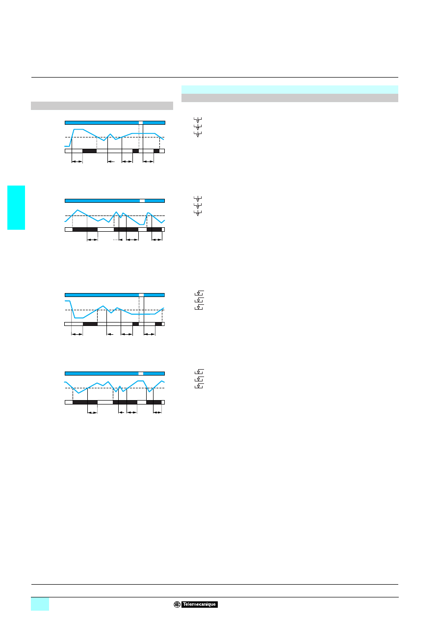
3/54
3
Operation
(continued)
3
Zelio Control
-
modular measurement
and control relays
3
Level control relays RM35 L
Level control relay: RM35 LM33MW (continued)
Configuration (continued)
Function diagrams
2222 Control of one level, empty function
1 Empty function T on
2 level: 1 - on delay functions:
-
LS (Low Sensitivity: 250
Ω…5 kΩ),
-
St (Standard Sensitivity: 5 k
Ω…100 kΩ),
-
HS (High Sensitivity: 50 k
Ω…1 MΩ).
When the liquid level rises above the probe for a time greater than the time delay
value Tt set on the front panel, the relay is energised and stays energised until the
liquid level drops back down to the probe.
If the liquid drops back down to below the set level before the end of the time delay,
the relay does not energise.
1 Empty function T off
2 level: 1 - off delay functions:
-
LS (Low Sensitivity: 250
Ω…5 kΩ),
-
St (Standard Sensitivity: 5 k
Ω…100 kΩ),
-
HS (High Sensitivity: 50 k
Ω…1 MΩ).
When the liquid level rises above the probe, the relay instantly energises and stays
energised until the liquid again reaches the probe level for a time Tt set on the front
panel.
If the liquid drops back down to below the set level before the end of the time delay
period, the relay stays energised.
2222 Control of one level, fill function
1 Fill function T on
2 level: 1 - on delay functions:
-
LS (Low Sensitivity: 250
Ω…5 kΩ),
-
St (Standard Sensitivity: 5 k
Ω…100 kΩ),
-
HS (High Sensitivity: 50 k
Ω…1 MΩ).
When the liquid level drops below the probe for a time greater than the time delay
value Tt set on the front panel, the relay is energised and stays energised until the
liquid level rises back up to the probe.
If the liquid rises back up to above the set level before the end of the time delay
period, the relay does not energise.
1 Fill function T off
2 level: 1 - off delay functions:
-
LS (Low Sensitivity: 250
Ω…5 kΩ),
-
St (Standard Sensitivity: 5 k
Ω…100 kΩ),
-
HS (High Sensitivity: 50 k
Ω…1 MΩ).
When the liquid level drops below the probe, the relay instantly energises and stays
energised until the liquid level again reaches the probe level and stays above it for
a time greater than the time delay period Tt set on the front panel.
If the liquid drops back down to below the set level before the end of the time delay
period, the relay stays energised.
11-12/11-14
21-22/21-24
Tt
Tt
Tt
Supply Un
Relays
Level
11-12/11-14
21-22/21-24
Tt
Tt
Tt
Tt
Supply Un
Relays
Level
11-12/11-14
21-22/21-24
Tt
Tt
Tt
Supply Un
Relays
Level
11-12/11-14
21-22/21-24
Tt
Tt
Tt
Supply Un
Relays
Level
Presentation, description :
page 3/52
Characteristics:
pages 3/56 and 3/57
References, dimensions :
page 3/57
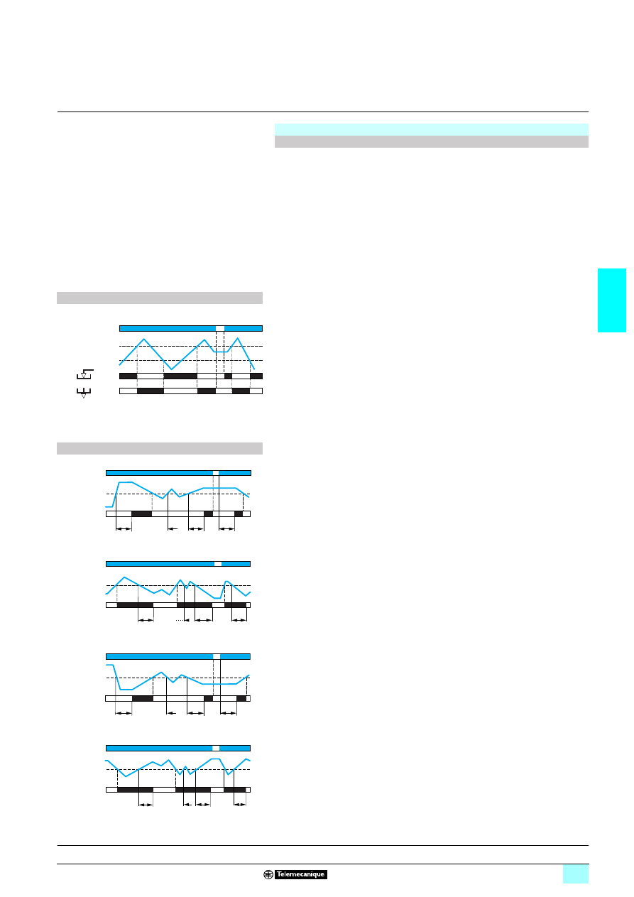
3/55
3
Operation
(continued)
3
Zelio Control
-
modular measurement
and control relays
3
Level control relays RM35 L
Level control relay: RM35 LV14MW
Configuration
A selector switch on the front panel allows selection of the function (empty or fill) and
the type of sensor.
A second switch allows selection of the number of levels (1 or 2) and the type of time
delay in the case of 1 level mode.
The configuration of these switches is taken into account on energisation.
If the switch is set to an unacceptable position, the product detects a fault, the output
relay stays open and the LEDs flash to signal the position error.
If the switch position is changed while the device is operating, all the LEDs flash, but
the product continues to operate normally with the function selected at the time of
energisation preceding the change of position.
The LED's return to their normal state if the switch is returned to the original position
selected prior to the last energisation.
Function diagram
2222 Control of two levels
26Fill/Empty function
2 empty function. Level: 2
The output relay stays open until the material level reaches the Max. probe. As soon
as the Max. level is reached, the contact closes and then allows emptying of the tank
(valve opens, pump starts, ...). When the level drops below the Min. probe, the
contact opens to stop the emptying process.
2 fill function. Level: 2
The output relay stays energised until the material level reaches the Max. probe. As
soon as the Max. level is reached, the contact opens and the pump stops. When the
level drops below the Min. probe, the contact closes again and pumping re-starts to
raise the level.
Note: When two levels are controlled, the anti-wave time delay function is not active.
Function diagrams
2222 Control of one level, empty function
26Empty function T on
2 level: 1 - on delay
When the material level rises above the probe for a time greater than the time delay
value Tt set on the front panel, the relay is energised and stays energised until the
material level drops back down to the probe.
If the level rises above the probe before the end of the time delay period, the relay
does not energise.
26Empty function T off
2 level: 1 - off delay
When the material level rises above the probe, the relay instantly energises and
stays energised until the material level again reaches the probe and stays below it
for a time greater than the time delay value Tt set on the front panel.
If the level drops back down to below the probe before the end of the time delay
period, the relay stays energised.
26Fill function T on
2222 Control of one level, fill function
2 level: 1 - on delay
When the material level drops below the probe for a time greater than the time delay
value Tt set on the front panel, the relay is energised and stays energised until the
material level again reaches the probe.
If the level rises above the probe before the end of the time delay period, the relay
does not energise.
2 Fill function T off
2 level: 1 - off delay
When the material level drops below the probe, the relay instantly energises and
stays energised until the material level again reaches the probe and stays above it
for a time greater than the time delay period Tt set on the front panel.
If the level drops back down to below the probe before the end of the time delay
period, the relay stays energised.
11-12/11-14
11-12/11-14
Supply Un
Relays
Relays
Max. level
Min. level
11-12/11-14
Tt
Tt
Tt
Supply Un
Relays
Level
11-12/11-14
Tt
Tt
Tt
Tt
Supply Un
Relays
Level
11-12/11-14
Tt
Tt
Tt
Supply Un
Relays
Level
11-12/11-14
Tt
Tt
Tt
Supply Un
Relays
Level
Presentation, description :
page 3/52
Characteristics:
pages 3/56 and 3/57
References, dimensions :
page 3/57
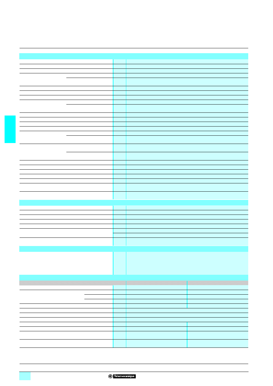
3/56
3
Characteristics
3
Zelio Control
-
modular measurement
and control relays
3
Level control relays RM35 L
Environment characteristics
Conforming to standards
NF EN 60255-6 and IEC 60255-6
Product certifications Pending
UL, CSA, GL, C-Tick, GOST
Marking
1
1
1
1: 73/23/EEC and EMC 89/336/EEC
Ambient air temperature
around the device
Storage
°C
- 40…+ 70
Operation
°C
- 20…+ 50
Permissible relative humidity Conforming to IEC 60068-2-30
2 x 24 hours…+ 95 % RH at + 55 °C (without condensation)
Vibration resistance
Conforming to IEC 60068-2-6
0.035 mm from 10…150 Hz
Shock resistance
Conforming to IEC 60068-2-6
5 gn
Degree of protection
Conforming to IEC 60529
Casing
IP 30
Terminals
IP 20
Degree of pollution
Conforming to IEC 60664-1
3
Overvoltage category
Conforming to IEC 60664-1
III
Insulation resistance
Conforming to 60664-1/60255-5
> 500 M
Ω,
2 500 V
Rated insulation voltage
Conforming to IEC 60664-1
V
250
Insulation test voltage
Conforming to
IEC 60664-1/60255-5
Dielectric test
kV
2,
1 50 Hz, 1 min.
Shock wave
kV
4 (1.2/50 µs)
Connection
Maximum c.s.a.
Conforming to IEC 60947-1
Solid cable without cable end
mm
2
1 conductor: 0.5…4 (AWG 20…AWG 11)
2 conductors: 0.5…2.5 (AWG 20…AWG 14)
Flexible cable with cable end
mm
2
1 conductor: 0.2…2.5 (AWG 24…AWG 12)
2 conductors: 0.2…1.5 (AWG 24…AWG 16)
Tightening torque
Conforming to IEC 60947-1
0.6…1N.m / 5.3…8.8 Lbf.In
Housing material
Self-extinguishing plastic
Power ON indicator
Green LED
Relay state indicator
Yellow LED
Timing indicator
Yellow LED
Mounting position
without derating
In relation to normal
vertical mounting plane
Any position
Mounting
Conforming to IEC/EN 60715
On
3 rail
Supply characteristics
Supply voltage Un
V
1/2 24…240
Operating range
V
1/2 20.4…264
Voltage limits
Of the power supply circuit
- 15 %, + 10 %
Frequency
Of the power supply circuit
50/60 Hz ± 10 %
Galvanic isolation, supply/measurement
Yes
Maximum power consumption at Un
VA
145
W
2 1.5
Immunity to microbreaks
ms
1 90, 2 100
Immunity to electromagnetic interference
Electromagnetic compatibility
Immunity NF EN 61000-6-2 2002 / IEC 61000-6-2
Emission NF EN 61000-6-4
NF EN 61000-6-3
IEC 61000-6-4
IEC 61000-6-3
Measurement circuit and input characteristics
Relay type
RM35 LM33MW
RM35 LV14MW
Measurement range
250
Ω…1 MΩ
–
Sub-measurement range
LS
250
Ω…5 kΩ
–
St
5 k
Ω…100 kΩ
–
HS
50 k
Ω…1 MΩ
–
Sensitivity adjustment
5…100 % of the range
–
Setting accuracy
± 10 % of the full scale / ± 20 % for the HS range
Measurement error with temperature variation
0.5 % / °C
Maximum voltage at the probe terminals
V
12
Maximum current across the probes
mA
< 1
40
Maximum probe cable length
m
100
100
Maximum capacity of probe cable
nF
1 for LS, 2.2 for St and 4.7 pour HS
10
Delay on pick-up
ms
600
500
Presentation, description :
page 3/52
Operation:
pages 3/53 to 3/55
References, dimensions :
page 3/57
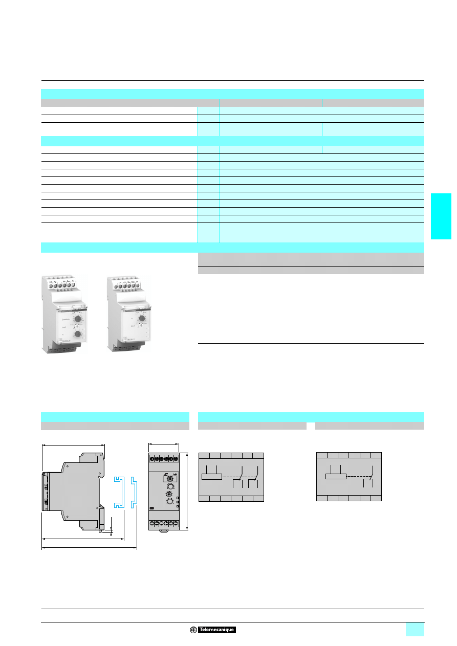
3/57
3
Characteristics
(continued)
references,
dimensions,
schemes
3
Zelio Control
-
modular measurement
and control relays
3
Level control relays RM35 L
Time delay characteristics
Relay type
RM35 LM33MW
RM35 LV14MW
Time delay on crossing the threshold
s
0.1…5, 0 + 10 %
Repeat accuracy (with constant parameters)
± 2 %
Reset time
s
1.75
4 if 1 line broken /
1 if 2 lines broken
Output characteristics
Type of output
2 C/O contacts
1 C/O contact
Contact type
Cadmium-free
Nominal current
A
5
Maximum switching voltage
V
1/2 250
Rated breaking capacity
VA
1250
Minimum breaking current
mA
10/
2 5 V
Maximum breaking current
A
1/2 5
Electrical durability
1 x 10
5
operating cycles
Mechanical durability
30 x 10
6
operating cycles
Maximum operating rate
360 operations/hour under full load
Utilisation categories
Conforming to IEC 60947-5-1
AC-12, AC-13, AC-14, AC-15, DC-12, DC-13
References
Function
Supply
voltage
Output
Reference
Weight
V
kg
Detection by
resistive probes
(see page 3/58)
1/2 24…240
2 C/O
5 A
RM35 LM33MW
0.130
Detection by
discrete sensors
(see page 3/60, references
XX5 12A
222
222
222
222)
1/2 24…240
1 C/O
5 A
RM35 LV14MW
0.130
Dimensions
Schemes
RM35 LM33MW, RM35 LV14MW
RM35 LM33MW
RM35 LV14MW
mm/In.
RM35 LM33MW
RM35 LV14MW
10
56
85
10
56
86
/
0
9
54.
3
35/
1.38
2,8
0.11
76/
2.99
72,5/
2.85
72/
2.83
11
12
14
22
21
24
21
11
12
14
24
22
A1
A2
C
Min Max
A1
A2
11
12
14
11
12
14
A1
A2
0V
Min Max
12V
NC
12V
A1
A2
Presentation, description :
page 3/52
Operation:
pages 3/53 to 3/55
Characteristics:
pages 3/56 and 3/57
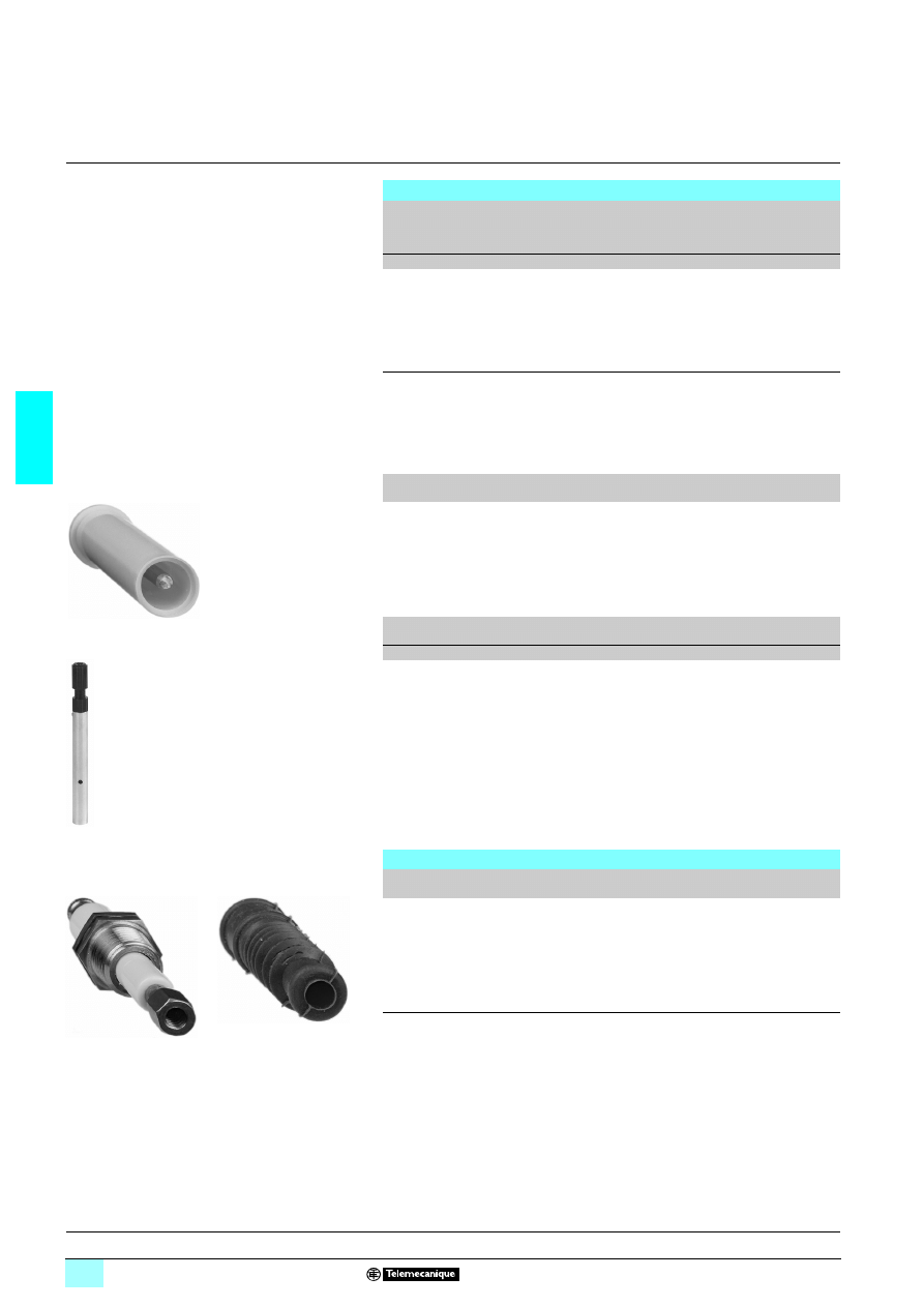
3/58
3
References
3
Zelio Control
-
modular measurement
and control relays
3
Electrode holders and probes
Probes
Application
No.
of
probes
Length
Opera-
ting
temper-
ature
Maximum
pressure
Reference
Weight
mm
°C
kg/cm
2
kg
Recommended
for drinks vending
machines and
where installation
space is limited
(Stainless steel)
3
1000
80
2
RM 79 696 044
0.800
Suitable for
boilers, pressure
vessels and under
high temperature
conditions (1)
(304 stainless
steel)
1
1000
200
25
RM 79 696 014
0.360
Description
Material
Reference
Weight
kg
Protected probe
for mounting by suspension
Protective shell
PUC (S7)
Electrode : stainless
steel
RM 79 696 043
0.150
Description
Type of
installation
Maximum operating
temperature
Reference
Weight
°C
kg
Liquid level
control probe
Suspended
by cable
100
LA9 RM201
0.100
Electrode holders
Description
Material
Reference
Weight
kg
Electrode for use up to 350 °C
and 15 kg/cm
2
(2)
Stainless steel
isolated by ceramic
RM 79 696 006
0.150
(1) 3/8" BSP mounting thread with hexagonal head. Use a 24 mm spanner for tightening.
(2) 3/8" BSP mounting thread.
RM 79 696 043
5
6
10
34
LA9 RM201
RM 79 696 006
56
10
3
5
56
10
3
6
Dimensions :
page 3/59
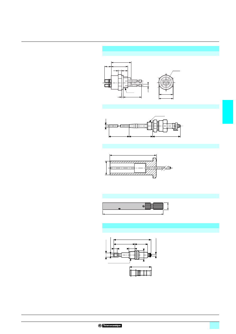
3/59
3
Dimensions
3
Zelio Control
-
modular measurement
and control relays
3
Electrode holders and probes
Probes
RM 79 696 044
38,5
32
7
3
14
26
Ø 27,5
Ø 11
12
11
100
PF 1/2
RM 79 696 014
60
Ø6
1000
60
G 3/8A
RM 79 696 043
Ø 25
80
LA9 RM201
150
16
Electrode holder
RM 79 696 006
46
29
84
6,5
49
20,7
13
9,5
A
c
ro
ss flats
1
/4
wh
it
5
/3
2
wh
it
3/8 tapered NPT
References :
page 3/58
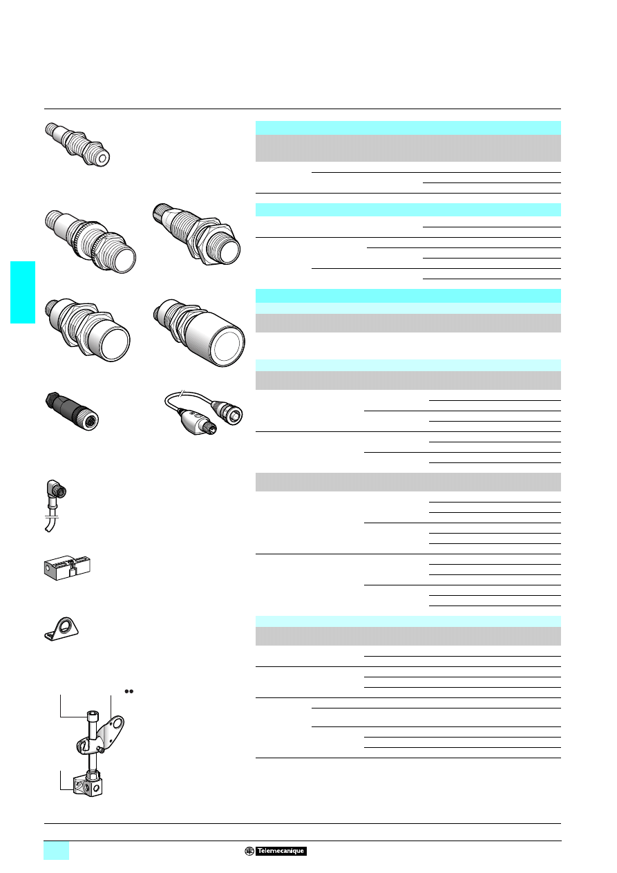
3/60
3
References
3
Ultrasonic sensors
3
Osisonic
®
, Optimum and Universal
(1)
Cylindrical plastic case, M12 x 1, M18 x 1, M30 x 1.5
d.c. supply, solid-state output
Optimum sensors
Sensors
Sensing
distance (Sn)
m
Function
Output
Reference
Weight
kg
Ø 12
0.05
NO
PNP/NPN
XX5 12A1KAM8 (1)
0.011
0.10
NO
NPN
XX5 12A2NAM8 (1)
0.011
PNP
XX5 12A2PAM8 (1)
0.011
Ø 18
0.15
NO
PNP/NPN
XX5 18A1KAM12
0.033
Universal sensors
Ø 18
0.50 (adjustable) NO
NPN
XX5 18A3NAM12
0.033
PNP
XX5 18A3PAM12
0.033
Ø 30
1 (adjustable)
NO
PNP/NPN
XX6 30A1KAM12
0.091
NO + NC
NPN
XX6 30A1NCM12 (2)
0.091
PNP
XX6 30A1PCM12 (2)
0.091
8 (adjustable)
NO + NC
NPN
XX6 30A3NCM12
0.110
PNP
XX6 30A3PCM12 0.110
Accessories
Teach mode pushbutton
Teach mode pushbutton
For use with
sensors
Reference
Weight
kg
Selection of detection window
Input: M12 female connector
Output: M12 male connector
XX5 18A3
7AM12
and XX7 V1A1
7AM12
XXZ PB100
0.035
Cabling accessories (4-wire output) (3)
Connectors
For use with
sensor
Type
Reference
Weight
kg
M8
Ø 12
Connection by
in-line IDC
Straight
XZ CC8FDM40V
0.010
Elbowed
XZ CC8FCM40V
0.010
Connection to
solder terminals
Straight
XZ CC8FDM40S
0.010
Elbowed
XZ CC8FCM40S
0.010
M12
Ø 18, Ø 30
Metal
clamping ring
Straight
XZ CC12FDM40B
0.020
Elbowed
XZ CC12FCM40B
0.020
Plastic
clamping ring
Straight
XZ CC12FDP40B
0.020
Elbowed
XZ CC12FCP40B
0.020
Pre-wired
connectors
For use with
sensor
Type
Length
m
Reference
Weight
kg
M8
Ø 12
Straight
2
XZ CP0166L2
0.080
5
XZ CP0166L5
0.180
10
XZ CP0166L10
0.360
Elbowed
2
XZ CP0266L2
0.080
5
XZ CP0266L5
0.180
10
XZ CP0266L10
0.360
M12
Ø 18, Ø 30
Straight
2
XZ CP1141L2
0.090
5
XZ CP1141L5
0.190
10
XZ CP1141L10
0.370
Elbowed
2
XZ CP1241L2
0.090
5
XZ CP1241L5
0.190
10
XZ CP1241L10
0.370
Fixing accessories
Description
For use with
sensor
Reference
Weight
kg
Fixing clamps
Ø 12
XSZ B112
0.006
Ø 18
XSZ B118
0.010
90° fixing bracket
Ø 12
XXZ 12
0.025
Ø 18
XUZ A118
0.038
Ø 30
XXZ 30
0.115
3D fixing kit
(4)
M12 rod
Ø 12, Ø 18 and Ø 30
XUZ 2001
0.050
Support for
M12 rod
Ø 12, Ø 18 and Ø 30
XUZ 2003
0.160
Ball-joint
mounted
fixing bracket
Ø 12
XUZ B2012
0.175
Ø 18
XUZ B2003
0.175
Ø 30
XUZ B2030
0.160
(1) Accessories recommended for RM35 LV14MW control relays.
(2) Sensor available with stainless steel 303 case. To order, replace the 1st letter A by the letter S.
(3) For 3-wire cabling accessories, refer to the Global Detection catalogue.
(4) To obtain a 3D fixing kit, order:
rod support XUZ 2003, M12 rod XUZ 2001 and ball-joint mounted fixing bracket XUZ B20
11
11
11
11.
XX5
218A1KAM12
56
64
5
4
7
56
45
31
XX6
230A1KAM12
XX6
230A31CM12
XX5
218A31AM12
53
271
3
56
45
33
XXZ PB100
56
45
30
56
45
34
56
453
5
XSZ B11
1
56
45
32
XUZ A118
XUZ 2003
XUZ 2001
B20
XUZ
53
25
17
3D fixing kit example
Characteristics:
page 3/61
Dimensions:
page 3/62
Schemes:
page 3/63
XX5
212A1KAM8
XZ
2CC12FD140B
XZ
2CP1041L1
56
45
46
5
3
22
43
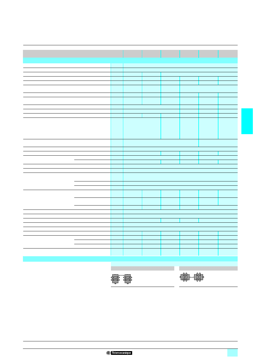
3/61
3
Characteristics,
setting-up
3
Ultrasonic sensors
3
Osisonic
®
, Optimum and Universal
Cylindrical plastic case, M12 x 1, M18 x 1, M30 x 1.5
d.c. supply, solid-state output
Sensor type
XX5
12A1
2222
2222
2222
2222
XX5
12A2
2222
2222
2222
2222
XX5
18A1
2222
2222
2222
2222
XX5
18A3
2222
2222
2222
2222
XX6
30A1
2222
2222
2222
2222
XX6
30A3
2222
2222
2222
2222
Characteristics
Product certifications
6
Conformity to standards
IEC 60947-5-2, UL508 pending and CSA C22-2 n° 14 pending
Connection
Connector
M8 - 4-pin
M8 - 3-pin
M12 - 4-pin
Sensing range
mm
6.4…51
6.4…102
19…152
51…508
51…991
203…8000
Nominal sensing distance (Sn)
m
0.05
0.1
0.15
0.50
1
8
Operating distance
mm
6.4…51
Fixed
6.4…102
Fixed
25…152
Fixed
Adjustable using teach mode
Differential travel
mm
< 0.7
< 0.7
< 0.35
< 2.5
< 2.5
< 12.7
Blind zone (no object must pass through this zone whilst the
sensor is operating)
mm
0…6.4
0…6.4
0…19
0…51
0…51
0…203
Transmission frequency
kHz
500
300
200
75
Repeat accuracy
mm
± 0.7
± 1.27
± 0.9
± 2.54
Overall beam angle (see detection lobe)
11°
10°
8°
6°
10°
16°
Minimum size of object to be detected
Cylinder Ø 2.5 mm or flat bar
1 mm wide
Cylinder
Ø 1.6 mm
Cylinder
Ø 2.5 mm
up to a
sensing
distance of
150 mm
Cylinder
Ø 1.6 mm
up to a
sensing
distance of
635 mm
Cylinder
Ø 50.8 mm
up to a
sensing
distance of
4732 mm
Degree of protection
Conforming to IEC 60529
and IEC 60947-5-2
IP 67
IP 65
Storage temperature
°C
- 40…+ 80
Operating temperature
°C
- 20…+ 65
0…+ 50
- 20…+ 65
0…+ 60
- 20…+ 60
Materials
Case
ULTEM
®
Valox
®
ULTEM
®
Sensing face
Epoxy
Silicone
Epoxy
Silicone
Epoxy
Vibration resistance
To IEC 60068-2-6
Amplitude ± 1 mm (f = 10…55 Hz)
Mechanical shock resistance
To IEC 60068-2-27
30 gn, duration 11 ms, in all 3 axes
Resistance to electromagnetic interference
Electrostatic discharges
To IEC 61000-4-2
kV
8, level 4
Radiated electromagnetic fields
To IEC 61000-4-3
V/m
10, level 3
Fast transients
To IEC 61000-4-4
kV
1, level 3
LED indicators
Output state
Yellow LED,
rear
Yellow LED –
Yellow LED Yellow LED,
rear
Yellow LED,
rear
Power on
Green LED,
rear
Green LED
–
Green LED
–
–
Setting-up assistance
–
–
–
Dual colour
Multicolour LED, rear
Rated supply voltage
V
2 12…24 V with protection against reverse polarity
Voltage limits (including ripple)
V
2 10…28 V
Current consumption, no-load
mA
25
60
40
50
Switching capacity
mA
< 100 (PNP and NPN) with overload and short-circuit protection
Voltage drop
V
< 1 (PNP and NPN)
Maximum switching frequency
Hz
125
125
80
40
10
2
Delays
First-up
ms
20
20
350
100
720
800
Response
ms
2
3
3
10
20
200
Recovery
ms
2
3
3
10
20
200
Deviation angle from 90° of the
object to be detected
± 10°
± 10°
± 10°
± 7°
± 7°
± 5°
Setting-up precautions
Minimum mounting distances
Side by side
Face to face
e: respect the distances indicated on the
detection curves shown on page 3/63.
e = 4 x Sn max.
e
e
Reference:
page 3/60
Dimensions:
page 3/62
Schemes:
page 3/63
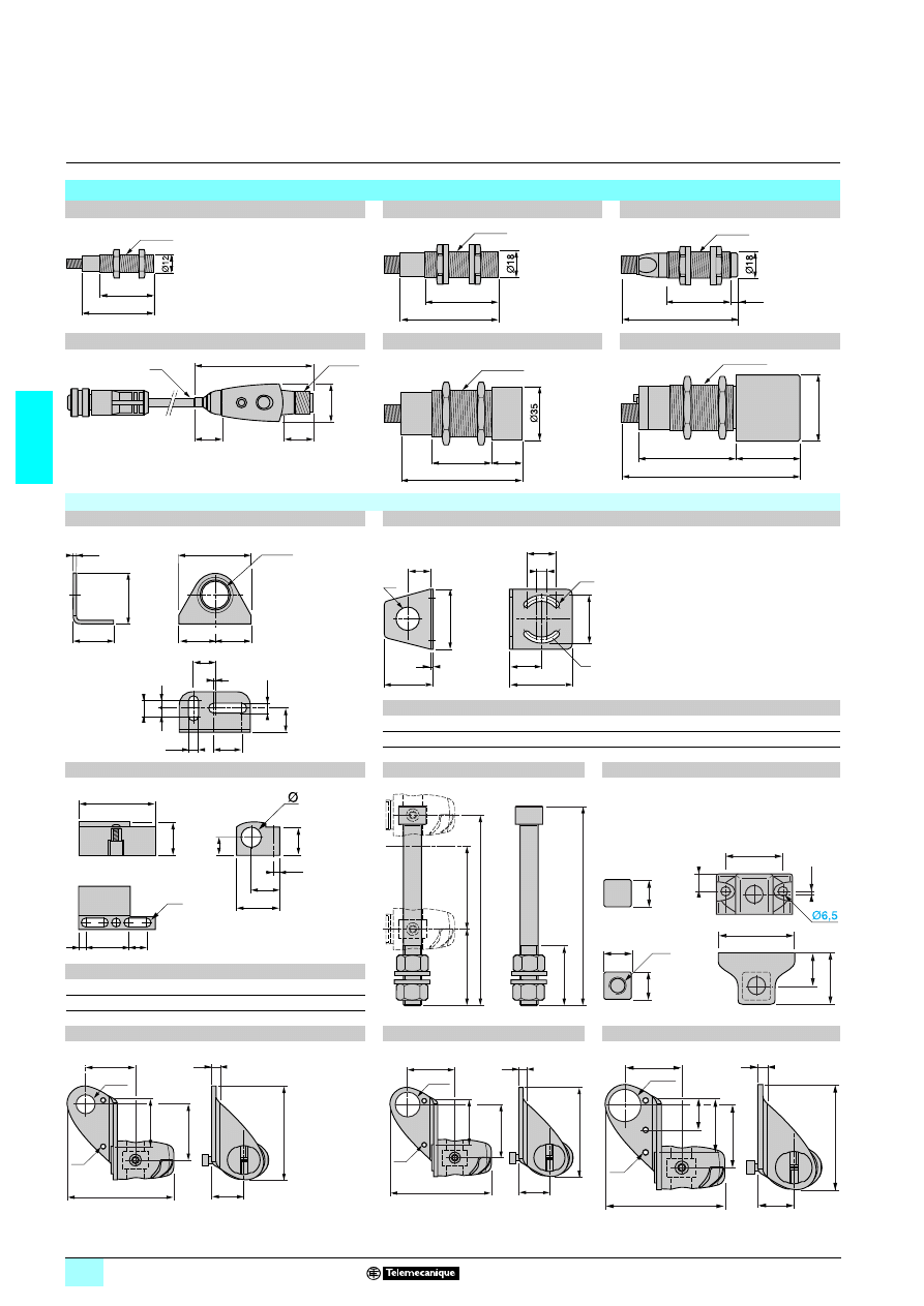
3/62
3
Dimensions
3
Ultrasonic sensors
3
Osisonic
®
, Optimum and Universal
Cylindrical plastic case, M12 x 1, M18 x 1, M30 x 1.5
d.c. supply, solid-state output
Dimensions
XX5 12A
22
22
22
22AM8
XX5 18A1KAM12
XX5 18A3
7AM12
XXZ PB100
XX6 30A1KAM12
XX6 30A3
2222CM12
(1) Cable, length: 152.4 mm.
Accessories
XUZ A118
XXZ 12, XXZ 30
90° fixing bracket (Ø 18)
90° fixing bracket (Ø 12 and Ø 30)
XXZ
a
b
c
c1
e
H
G
G1
Ø
Ø1
12
35
40
33
18
2
31
18
18
25
13
30
67
65
52
25
3
51
35
33
50
31
XSZ B112, XSZ B118
XUZ 2001
XUZ 2003
Fixing clamps (Ø 12 and Ø 18)
M12 rod
Support for M12 rod
XSZ
a
a1
b
b1
b2
Ø
B112
21.9
14.5
16
15.5
8.5
12
B118
26
15.7
22.3
20.1
11.5
18
(1) 2 elongated holes Ø 4 x 8.
XUZ B2012
XUZ B2003
XUZ 2030
Ball-joint mounted fixing bracket (Ø 12)
Ball-joint mounted fixing bracket (Ø 18)
Ball-joint mounted fixing bracket (Ø 30)
M12x1
50
38
65
51
M18x1
M18x1
77,7
43
4,7
63
16
14,5
(1)
M12x1
20
85
45
20
M30x1,5
117,35
42,1
64,3
M30x1,5
Ø43,2
2,5
Ø18,2
35
28
1
15
20
6,5
6,5
=
10
=
16,5
=
=
50
a
10
Ø5
Ø1
G1
Ø
G
H
c1
c
e
b
4
8
22,3
(1)
38,3
b
b2
a
3,5
b1
a1
126
50
55
132
40
23
40
M12
1,9
12
19
53
36
19
19
5,7
22,9
40
33
36
76,5
M4
Ø12,4
67
5,7
22,9
40
33
36
76,5
M4
Ø18,5
67
6
22,9
46,3
24,1
42,2
90,5
M3
81,7
13
Ø30,5
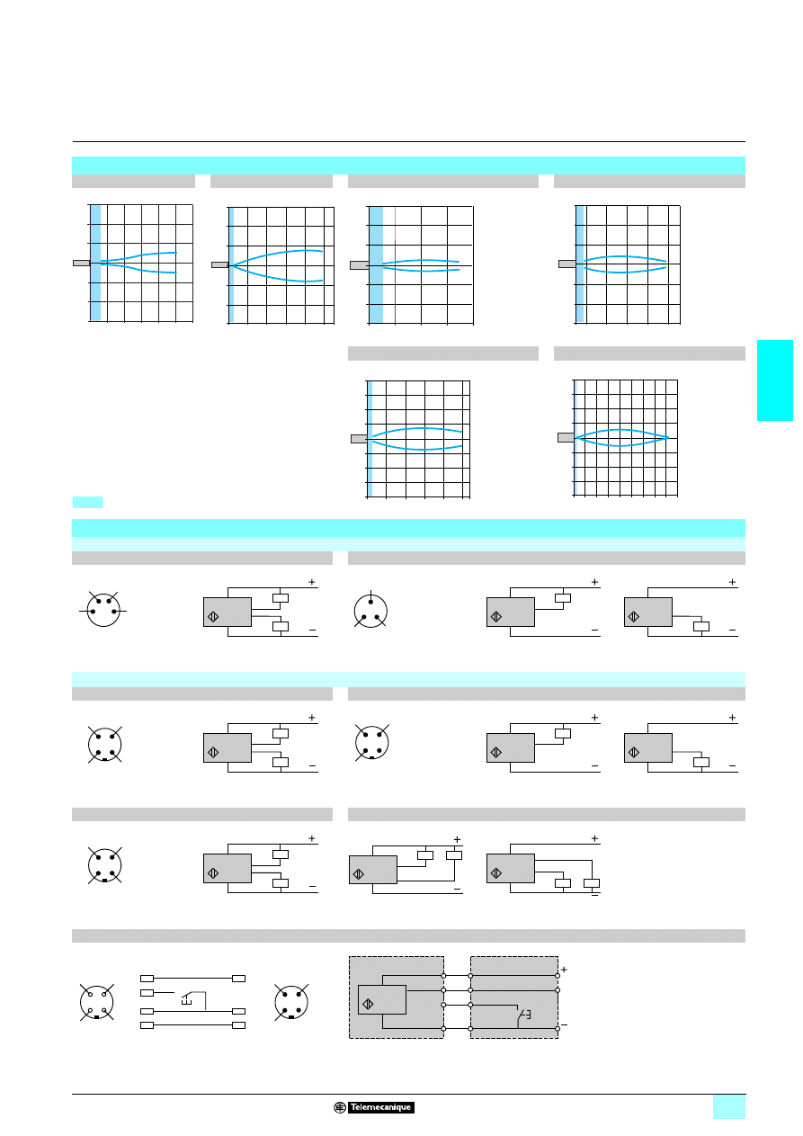
3/63
3
Curves,
schemes
3
Ultrasonic sensors
3
Osisonic
®
, Optimum and Universal
Cylindrical plastic case, M12 x 1, M18 x 1, M30 x 1.5
d.c. supply, solid-state output
Detection curves
XX5 12A1KAM8
XX5 12A2
2222NAM8
XX5 18A1KAM12
XX5 18A3
2222AM12
XX6 30A1
2222CM12
XX6 30A3
2222CM12
Blind zone
Wiring schemes
M8 connector
XX5 12A1KAM8
XX5 12A2
2222
4-wire type
NO outputs, PNP and NPN
3-wire type
NO outputs, NPN
NO outputs, PNP
1 (+)
2 PNP output
3 (-)
4 NPN output
(-) BU (Blue) (+) BN (Brown)
WH (White)
BK (Black)
1 (+)
3 (-)
4 NPN or PNP output
(-) BU (Blue) (+) BN (Brown)
BK (Black)
M12 connector
XX5 18A1KAM12
XX5 18A3
2222
4-wire type
NO outputs, PNP and NPN
3-wire type
NO outputs, NPN
NO outputs, PNP
1 (+)
2 PNP output
3 (-)
4 NPN output
(-) BU (Blue) (+) BN (Brown)
WH (White)
BK (Black)
1 (+)
3 (-)
4 NPN or PNP output
(-) BU (Blue) (+) BN (Brown)
BK (Black)
XX6 30A1KAM12
XX6 30A
22
22
22
22CM12
4-wire type
NO outputs, PNP and NPN
NO + NC outputs, NPN
NO + NC outputs, PNP
1 (+)
2 PNP output
3 (-)
4 NPN output
(-) BU (Blue) (+) BN (Brown)
WH (White)
BK (Black)
(-) BU (Blue) (+) BN (Brown)
WH (White)
BK (Black)
XXZ PB100 (teach mode pushbutton for XX5 18A3
7AM12)
1 (+) BN (Brown) 2 WH (White)
3 (-) BU (Blue)
4 BK (Black)
0
10
20
30
40
50 60
-20
-30
-10
10
20
30
mm
mm
cm
2
4
6
8
10
0
10
-10
20
30
-20
-30
mm
100
150
200
50
0
mm
40
-40
80
120
-80
-120
mm
65
190 320 445 570
mm
0
mm
100
-100
200
300
-200
-300
20
40
60
80 100
cm
0
100
-100
200
300
400
-200
-300
-400
mm
2
4
6
8 m
0
100
-100
200
300
400
-200
-300
-400
cm
4
3
2
1
2/WH
3/BU
4/BK
1/BN
NPN
PNP
4
1
3
3/BU
4/BK
1/BN
NPN
4/BK
3/BU
1/BN
PNP
3
2
4
1
2/WH
3/BU
4/BK
1/BN
NPN
PNP
3
2
4
1
3/BU
4/BK
1/BN
NPN
4/BK
3/BU
1/BN
PNP
3
2
4
1
2/WH
3/BU
4/BK
1/BN
NPN
PNP
3/BU
2/WH 4/BK
1/BN
NPN
NC
NO
3/BU
2/WH
4/BK
1/BN
NPN
NC
NO
4
4
1
1
3
3
4
1
3
2
2
4
1
3
Sensor side
M12 male
connector
M12 female
connector
Output
XXZ PB100
3/BU
1/BN
1/BN
NO
2/WH
4/BK
3/BU
4/BK
XX5 18A3
XXZ PB100
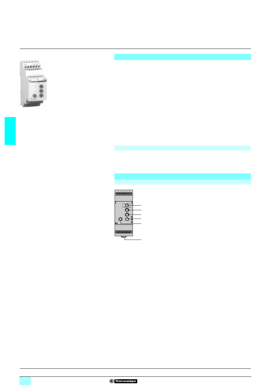
3/64
3
Presentation,
description
3
Zelio Control
-
modular measurement
and control relays
3
3-phase and single-phase pump control relays
RM35 BA
Presentation
Measurement and control relay RM35 BA10 is used for control and monitoring of
3-phase and single-phase pumps.
It monitors:
1 The sequence of phases L1, L2 and L3.
1 The absence of one or more phases,
1 Undercurrent for protection against running empty,
1 Overcurrent for protection against overload.
This control relay accepts different nominal voltage values:
1 4 208… 480 V in 3-phase mode,
1 4 230 V in single-phase mode.
It is self-powered and measurements are true rms values.
Settings are protected by a sealable cover.
Control status is indicated by a LED.
The relay is designed for clip-on mounting on
5 rail
Applications
1 Management of pumps.
Description
RM35 BA
1
Configuration: selection of active function and
operating mode.
3ph/1ph (Double - Single).
2
Overcurrent setting potentiometer.
>
I
3
Undercurrent setting potentiometer.
<
I
4
Time delay adjustment potentiometer. Tt
5
Starting inhibition time delay adjustment
potentiometer. Ti
6
Spring for clip-on mounting on 35 mm
5 rail.
Def. Yellow LED: indicates fault present status.
Un Green LED: indicates that supply to the relay is on.
R
Yellow LED: indicates relay output state.
RM35 BA10
10
56
91
E1
Y1
12 11 14
Y2
L2 L3
L1
Def.
Un
R
> I
< I
1
2
3
4
5
6
Operation:
pages 3/65 and 3/66
Characteristics:
pages 3/66 and 3/67
References, dimensions :
page 3/68
Schemes:
page 3/69
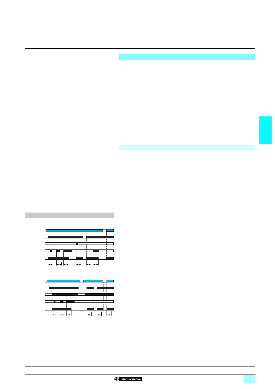
3/65
3
Operation
3
Zelio Control
-
modular measurement
and control relays
3
3-phase and single-phase pump control relays
RM35 BA
Operating principle
Pump control relay RM35 BA10 can operate on a single-phase or 3-phase supply.
It incorporates 3 functions in a single unit:
1 Current control,
1 Phase presence control (in 3-phase mode),
1 Phase sequence control (in 3-phase mode).
It has two operating modes which are designed to control a pump via two external
signal inputs (Y1 Y2).
These two signals are controlled by volt-free contacts.
Control inputs Y1 and Y2 can be connected to:
1 A level sensor,
1 A level relay,
1 A pressure sensor,
1 A pushbutton, etc...
Fault signalling is by LED with differentiation of the cause of the fault.
3-phase and single-phase pump control relay
The operating mode is fixed by the user:
A switch allows selection between the following modes:
1 Single control,
1 Double control,
1 Single-phase or 3-phase supply.
The position of the switch, and therefore the operating mode, is read by the product
on energisation.
If the switch position is changed while the device is operating, all the LEDs flash, but
the product continues to operate normally with the function selected at the time of
energisation preceding the change of position.
The LED's return to their normal state if the switch is returned to the original position
selected prior to the last energisation.
Function diagrams
Single control mode
1 Functions :
2 Single control mode (3ph/1ph).
This mode is designed to control a pump via an external signal.
The relay output is closed when the signal is present at Y1 (contact closed).
Y2 can be used to reset the relay after a current fault.
2 Double control mode (3ph/1ph).
Double control mode
This mode is designed to control a pump via two external control signals
(Y1 and Y2).
The output relay closes when both input signals are present (Y1 and Y2 closed).
It will open as soon as one of these signals disappears.
Ti: time delay to inhibit fault monitoring on starting of pump
(overcurrent and undercurrent, setting on front panel).
Tt: time delay in the event of a fault (overcurrent or
undercurrent, setting on front panel).
I. Def.: presence of a current fault (overcurrent or undercurrent)
Tt
Tt
Tt
Ti
Ti
Ti
Y1
Y2
I
I.Def.
11-12
11-14
Relays
Supply Un
Ti
Ti
Ti
Tt
Ti
Tt
Y1
Y2
I.Def.
11-12
11-14
Relays
Supply Un
Presentation, description :
page 3/64
Characteristics:
pages 3/66 and 3/67
References, dimensions :
page 3/68
Schemes:
page 3/69
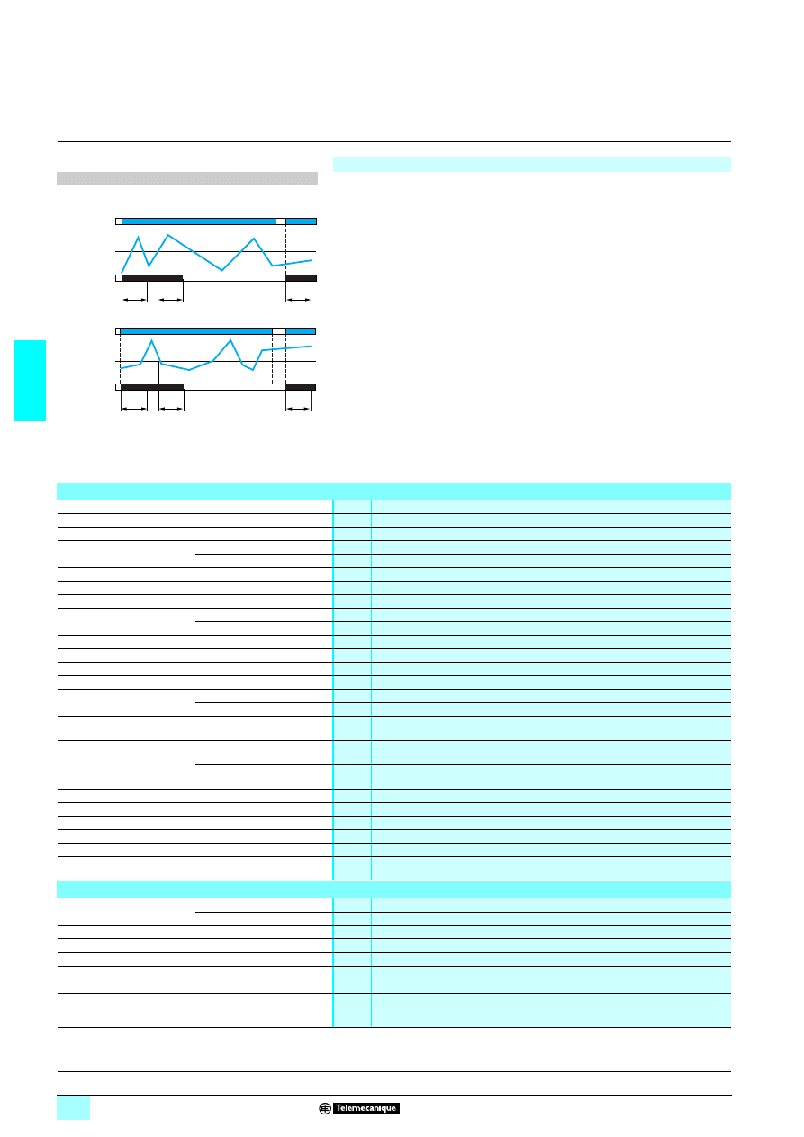
3/66
3
Operation
(continued),
characteristics
3
Zelio Control
-
modular measurement
and control relays
3
3-phase and single-phase pump control relays
RM35 BA
3-phase and single-phase pump control relay (continued)
Function diagrams
1 Control
If the control relay is configured for a single-phase supply, it monitors the current
consumed by the pump.
If the control relay is configured for a 3-phase supply, it monitors the current, phase
sequence and phase failure.
If a phase fault is detected, the output relay opens immediately.
On energisation, if there is a phase sequence or phase failure fault, the output is
unable to energise.
The overcurrent and undercurrent values are set by two separate potentiometers,
graduated from 1 to 10 A.
In the event of a setting error (low threshold greater than high threshold) the output
relay is open and all the LEDs flash to signal the error.
If a current fault occurs (overcurrent or undercurrent) the relay opens when the fault
persists for longer than the threshold time delay setting.
When the current returns to a correct value, the output relay stays open. It can only
be re-energised by a RESET: either by switching off the power,
or by closing of external contact Y2 (in single control mode).
An inhibition time delay on energisation (Ti) allows detection of current peaks on
starting of the motor.
1 Functions :
2 Overcurrent detection.
>
I
2 Undercurrent detection.
<
I.
Ti : time delay to inhibit fault monitoring on starting of pump
(overcurrent and undercurrent, setting on front panel).
Tt: time delay in the event of a fault (overcurrent or
undercurrent, setting on front panel).
Environment characteristics
Conforming to standards
NF EN 60255-6 and IEC 60255-6
Product certifications
Pending
UL, CSA, GL, C-Tick, GOST
Marking
1
1
1
1: 73/23/EEC and EMC 89/336/EEC
Ambient air temperature
around the device
Storage
°C
- 40…+ 70
Operation
°C
- 20…+ 50
Permissible relative humidity Conforming to IEC 60068-2-30
2 x 24 hours…+ 95 % RH at + 55 °C (without condensation)
Vibration resistance
Conforming to IEC 60068-2-6
0.035 mm from 10…150 Hz
Shock resistance
Conforming to IEC 60068-2-27
5 gn
Degree of protection
Conforming to IEC 60529
Casing
IP 30
Terminals
IP 20
Degree of pollution
Conforming to IEC 60664-1
3
Overvoltage category
Conforming to IEC 60664-1
III
Insulation resistance
Conforming to 60664-1/60255-5
> 500 M
Ω,
2 500 V
Rated insulation voltage
Conforming to IEC 60664-1
V
400
Insulation test voltage
Dielectric test
kV
2,
1 50 Hz, 1 min.
Shock wave
kV
4
Mounting position
without derating
In relation to normal
vertical mounting plane
Any position
Connection
Maximum c.s.a.
Conforming to IEC3 60947-1
Solid cable without cable end
mm
2
1 conductor: 0.5…4 (AWG 20…AWG 11)
2 conductors: 0.5…2.5 (AWG 20…AWG 14)
Flexible cable with cable end
mm
2
1 conductor: 0.2…2.5 (AWG 24…AWG 12)
2 conductors: 0.2…1.5 (AWG 24…AWG 16)
Tightening torque
Conforming to IEC 60947-1
0.6…1 N.m / 5.3…8.8 Lbf.In
Housing material
Self-extinguishing plastic
Power ON indicator
Green LED
Relay state indicator
Yellow LED
Fault indication
Yellow LED
Mounting
Conforming to IEC/EN 60715
On 35 mm
3 rail
Supply characteristics
Rated supply voltage Un
3-phase
V
1 208…480
Single-phase
V
14230
Operating range
V
1 183…528
Voltage limits
Of the power supply circuit
- 15 %, + 10 %
Frequency
Of the power supply circuit
50/60 Hz ± 10 %
Galvanic isolation, supply/measurement
No
Maximum power consumption
VA
145
Immunity to microbreaks
ms
500
Ti
Tt
Ti
I
I
>
11-12/11-14
Relays
Supply Un
11-12/11-14
Ti
Tt
Ti
I
I
<
Relays
Supply Un
Presentation, description :
page 3/64
Operation:
pages 3/65 and 3/66
References, dimensions :
page 3/68
Schemes:
page 3/69

3/67
3
Characteristics
(continued),
3
Zelio Control
-
modular measurement
and control relays
3
3-phase and single-phase pump control relays
RM35 BA
Immunity to electromagnetic interference
Electromagnetic compatibility
Immunity NF EN61000-6-2 / IEC 61000-6-2
Emission NF EN 61000-6-4, NF EN 61000-6-3, IEC 61000-6-4, IEC 61000-6-3
Measurement circuit and input characteristics
Measurement range
A
1 1…10
Input resistance
Ω
E1 - L2 : 0.01
Overload
Permanent at 25 °C
A
11 (E1-L2)
Non repetitive < 1 s at 25 °C
A
50 (E1-L2)
Frequency of the measured signal
Hz
50…60 ± 10 %
Maximum measuring cycle
ms
140/measurement as true rms value
Hysteresis
5 % of the threshold
Setting accuracy
± 10 % of the threshold setting (of the full scale value)
Repeat accuracy (with constant parameters)
± 1 %
Measurement error with voltage variation
1 % / V over the whole range
Measurement error with temperature variation
± 0.05 % / °C
Time delay characteristics
Time delay on energisation Ti
s
1…60. 0 + 10 %
Time delay on crossing the threshold Tt
s
0.1…10. 0 + 10 %
Repeat accuracy (with constant parameters)
± 1 %
Reset time
s
2
Minimum duration Y2 (reset)
ms
300
Response time in the event of a fault
ms
< 300
Delay on pick-up
ms
500
Output characteristics
Type of output
1 C/O contact
Contact type
Cadmium-free
Maximum switching voltage
V
1/2 250
Rated breaking capacity
VA
1250
Maximum breaking current
A
1/2 5
Minimum breaking current
10 mA/
2 5 V
Mechanical durability
30 x 10
6
operating cycles
Electrical durability
1 x 10
5
operating cycles
Maximum operating rate
360 operations/hour under full load
Utilisation categories
Conforming to IEC 60947-5-1
AC-12, AC-13, AC-14, AC-15, DC-12, DC-13
Presentation, description :
page 3/64
Operation:
pages 3/65 and 3/66
References, dimensions :
page 3/68
Schemes:
page 3/69
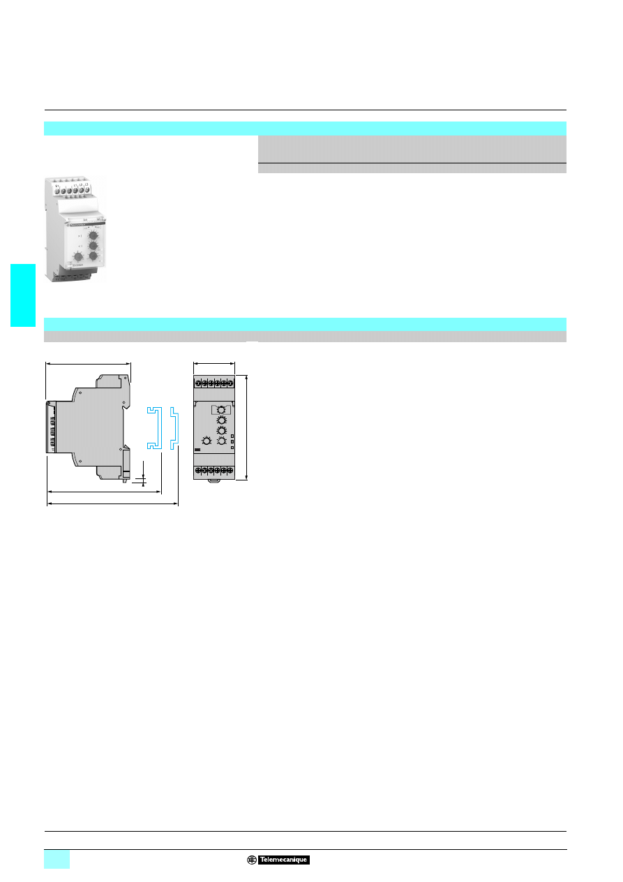
3/68
3
Reference,
dimensions
3
Zelio Control
-
modular measurement
and control relays
3
3-phase and single-phase pump control relays
RM35 BA
Reference
Function
Current
range
controlled
Supply
voltage
Output Reference
Weight
A
V
kg
3-phase:
5 Phase sequence
5 Phase failure
5 Overcurrent and
undercurrent control
Single-phase :
5 Overcurrent and
undercurrent control
1…10
1 4 208…480,
3-phase
1 4 230,
single-phase
1 C/O
5 A
RM35 BA10
0.110
Dimensions
RM35 BA10
mm/In.
RM35 BA10
105
69
1
2,8
0.11
76/
2.99
72,5/
2.85
72/
2.83
90/
3.54
35/
1.38
E1
Y1
12 11 14
Y2
L2 L3
L1
Def.
Un
R
> I
< I
Presentation, description :
page 3/64
Operation:
pages 3/65 and 3/66
Characteristics:
pages 3/66 and 3/67
Schemes:
page 3/69
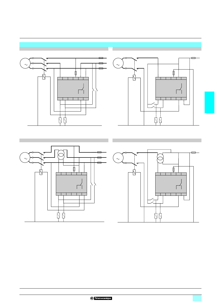
3/69
3
Schemes
3
Zelio Control
-
modular measurement
and control relays
3
3-phase and single-phase pump control relays
RM35 BA
Schemes RM35 BA10
3-phase < 10 A
Single-phase
45
45
45
45 230 V < 10 A
(1) 100 mA quick-blow fuse or circuit-breaker.
3-phase > 10 A
Single-phase
45
45
45
45 230 V > 10 A
(1) 100 mA quick-blow fuse or circuit-breaker.
M
3
F1
(1)
L1
L2
L3
KM1
U1
W1
V1
N
L1
L2
L3
E1
Y1
Y2
11
12
14
11
12
14
R
M
U
V
KM1
N
L1
L2
L3
E1
Y1
Y2
11
12
14
11
12
14
Ph
F1
(1)
R
L1
L2
L3
KM1
U1
W1
V1
M
3
N
L1
L2
L3
E1
Y1
Y2
11
12
14
11
12
14
T.I.
F1
(1)
R
M
T.I.
U
V
Ph
KM1
N
L1
L2
L3
E1
Y1
Y2
11
12
14
11
12
14
F1
(1)
R
Presentation, description :
page 3/64
Operation:
pages 3/65 and 3/66
Characteristics:
pages 3/66 and 3/67
References, dimensions :
page 3/68
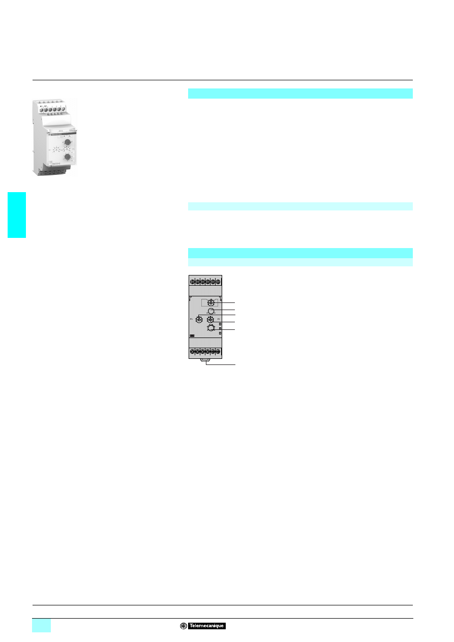
3/70
3
Presentation,
description
3
Zelio Control
-
modular measurement
and control relays
3
Frequency control relay
RM35 HZ
Presentation
Frequency control relay RM35 HZ monitors frequency variations on 50 or 60 Hz
a.c. supplies:
1 Over-frequency and under-frequency with two independent relay outputs.
1 Selectable memory function.
It monitors its own supply voltage, measured as a true rms value.
Settings are protected by a sealable cover.
Control status is indicated by a LED.
The relay is designed for clip-on mounting on
5 rail
Applications
Monitoring of electrical power sources:
1 Generating sets, wind turbines, micro-power stations...
Description
RM35 HZ21FM
1
Configuration: selection of 50/60 Hz frequency range and operating mode (with or
without memory). Memory - No Memory
2
Frequency threshold multiplication switch. x1-x2
3
Low frequency threshold setting switch. F
<
4
High frequency threshold setting switch. F
>
5
Time delay adjustment potentiometer.
6
Spring for clip-on mounting on 35 mm
5 rail.
R1 Yellow LED: indicates relay state (high frequency threshold).
Un Green LED: indicates that supply to the relay is on.
R2 Yellow LED: indicates relay state (low frequency threshold).
RM35 HZ21FM
10
56
84
A1
12
22
14
21 24
11
A2
R1
Un
R2
1
2
3
4
5
6
Operation:
page 3/71
Characteristics:
pages 3/72 and 3/73
References, dimensions :
page 3/73
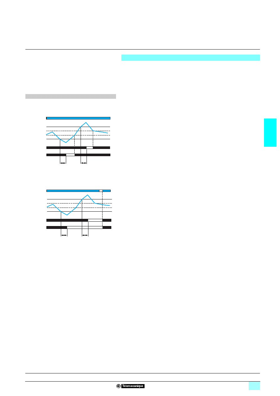
3/71
3
Operation
3
Zelio Control
-
modular measurement
and control relays
3
Frequency control relay
RM35 HZ
Operating principle
Frequency control relay RM35 HZ monitors:
2 Frequency variations on 50 or 60 Hz supplies.
2 It allows monitoring of over-frequency and under-frequency, via adjustment of two
independent thresholds. It has two relay outputs: one per threshold.
Fault signalling is by LED.
2222 Function selector switch:
2 Set the switch to frequency of 50 or 60 Hz of the supply monitored, then select
Memory or No memory mode. The position of the switch, and therefore the operating
mode, is read by the product on energisation.
2 If the switch is set to an unacceptable position, the product detects a fault, the
output relays stay open and the LEDs flash to signal the position error.
2 If the switch position is changed while the device is operating, all the LEDs flash,
but the product continues to operate normally with the function selected at the time
of energisation preceding the change of position.
2 The LED's return to their normal state if the switch is returned to the original
position selected prior to the last energisation.
1 The relay monitors its own supply voltage Un:
The under-frequency or over-frequency threshold values are set by means of two
graduated potentiometers indicating the variation value of the frequency to be
monitored.
A switch x1 / x2 allows the control scale to be doubled. Hysteresis is fixed at 0.3 Hz.
If the frequency of the voltage controlled exceeds the over-frequency threshold
setting for a time greater than that set on the front panel (0.1…10 s), the
corresponding output relay opens and its LED goes out. During the time delay, this
LED flashes.
As soon as the frequency drops below the value of the threshold setting, minus the
hysteresis, the relay instantly closes.
If the frequency of the voltage controlled falls below the under-frequency threshold
setting for a time greater than that set on the front panel (0.1…10 s), the
corresponding output relay opens and its LED goes out. During the time delay, this
LED flashes.
As soon as the frequency rises above the value of the threshold setting, plus the
hysteresis, the relay instantly closes.
On energisation of the device with a fault measured, the relay stays open.
1 "Memory" mode:
If "Memory" mode is selected, the relay opens after the time delay and stays in that
position when crossing of the threshold is detected.
The power must be switched off to reset the product.
Function diagrams
1 Function: Over-frequency and under-frequency
control
2 (without memory) No Memory.
Tt: time delay after crossing of threshold (adjustable on front
panel)
3333 (with memory) Memory.
Tt: time delay after crossing of threshold (adjustable on front
panel)
Tt
Tt
F
11-12
11-14
21-22
21-24
F
>
F
<
Relay R1
Hysteresis
Supply Un
Relay R2
Hysteresis
Tt
Tt
F
11-12
11-14
21-22
21-24
F
>
F
<
Relay R1
Hysteresis
Supply Un
Relay R2
Hysteresis
Presentation, description :
page 3/70
Characteristics:
pages 3/72 and 3/73
References, dimensions :
page 3/73
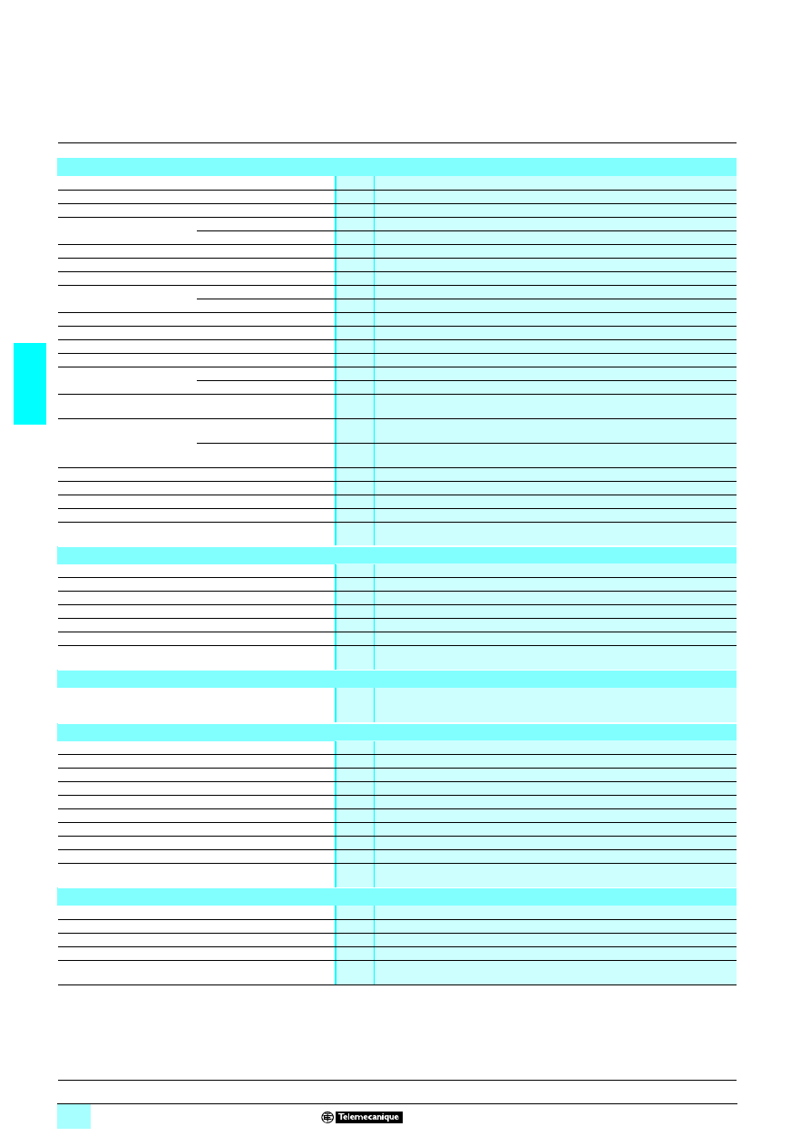
3/72
3
Characteristics
3
Zelio Control
-
modular measurement
and control relays
3
Frequency control relay
RM35 HZ
Environment characteristics
Conforming to standards
NF EN 60255-6 and IEC 60255-6
Product certifications
Pending
UL, CSA, GL, C-Tick, GOST
Marking
1
1
1
1: 73/23/EEC and EMC 89/336/EEC
Ambient air temperature
around the device
Storage
°C
- 40…+ 70
Operation
°C
- 20…+ 50
Permissible relative humidity Conforming to IEC 60068-2-30
2 x 24 hours…+ 95 % RH at + 55 °C (without condensation)
Vibration resistance
Conforming to IEC 60068-2-6
0.035 mm from 10…150 Hz
Shock resistance
Conforming to IEC 60068-2-6
5 gn
Degree of protection
Conforming to IEC 60529
Casing
IP 30
Terminals
IP 20
Degree of pollution
Conforming to IEC 60664-1
3
Overvoltage category
Conforming to IEC 60664-1
III
Insulation resistance
Conforming to 60664-1/60255-5
> 500 M
Ω,
2 500 V
Rated insulation voltage
Conforming to IEC 60664-1
V
400
Insulation test voltage
Dielectric test
kV
2,
1 50 Hz, 1 min.
Shock wave
kV
4
Mounting position
without derating
In relation to normal
vertical mounting plane
Any position
Connection
Maximum c.s.a.
Conforming to IEC3 60947-1
Solid cable without cable end
mm
2
1 conductor: 0.5…4 (AWG 20…AWG 11)
2 conductors: 0.5…2.5 (AWG 20…AWG 14)
Flexible cable with cable end
mm
2
1 conductor: 0.2…2.5 (AWG 24…AWG 12)
2 conductors: 0.2…1.5 (AWG 24…AWG 16)
Tightening torque
Conforming to IEC 60947-1
0.6…1 N.m / 5.3…8.8 Lbf.In
Housing material
Self-extinguishing plastic
Power ON indicator
Green LED
Relay state indication (R1-R2)
Yellow LEDs. These LEDs flash during the delay on crossing the threshold
Mounting
Conforming to IEC/EN 60715
On 35 mm
3 rail
Supply characteristics
Rated supply voltage Un
V
1 120…277
Operating range
V
1 102…308
Voltage limits
Of the power supply circuit
- 15 %, + 10 Hz
Frequency
Of the power supply circuit
50/60 Hz ± 10 Hz
Galvanic isolation, supply/measurement
No
Maximum power consumption
VA
146
Immunity to microbreaks
ms
10
Immunity to electromagnetic interference
Electromagnetic compatibility
Immunity NF EN 61000-6-2 / IEC 61000-6-2
Emission NF EN 61000-6-4, NF EN 61000-6-3, IEC 61000-6-4, IEC 61000-6-3
Measurement circuit and input characteristics
Measurement range
Hz
40…70
Frequency of the measured signal
Hz
40…70
Maximum measuring cycle
ms
200, measured as true rms value
Threshold setting
Hz
- 10…+ 2 and - 2…+ 10
Adjustable or fixed hysteresis
Hz
0.3 fixed
Setting accuracy
± 10 % of the full scale value
Repeat accuracy (with constant parameters)
± 0.5 %
Measurement error with voltage variation
< ± 1 % over the whole range
Measurement error with temperature variation
± 0.05 % / °C
Maximum frequency of input signals
Hz
70 max
Time delay characteristics
Time delay on crossing the threshold
s
0.1…10, 0 + 10 %
Setting accuracy
± 10 % of the full scale value
Repeat accuracy (with constant parameters)
± 0.5 %
Reset time
ms
2000
Delay on pick-up
ms
500
Presentation, description :
page 3/70
Operation:
page 3/71
References, dimensions :
page 3/73
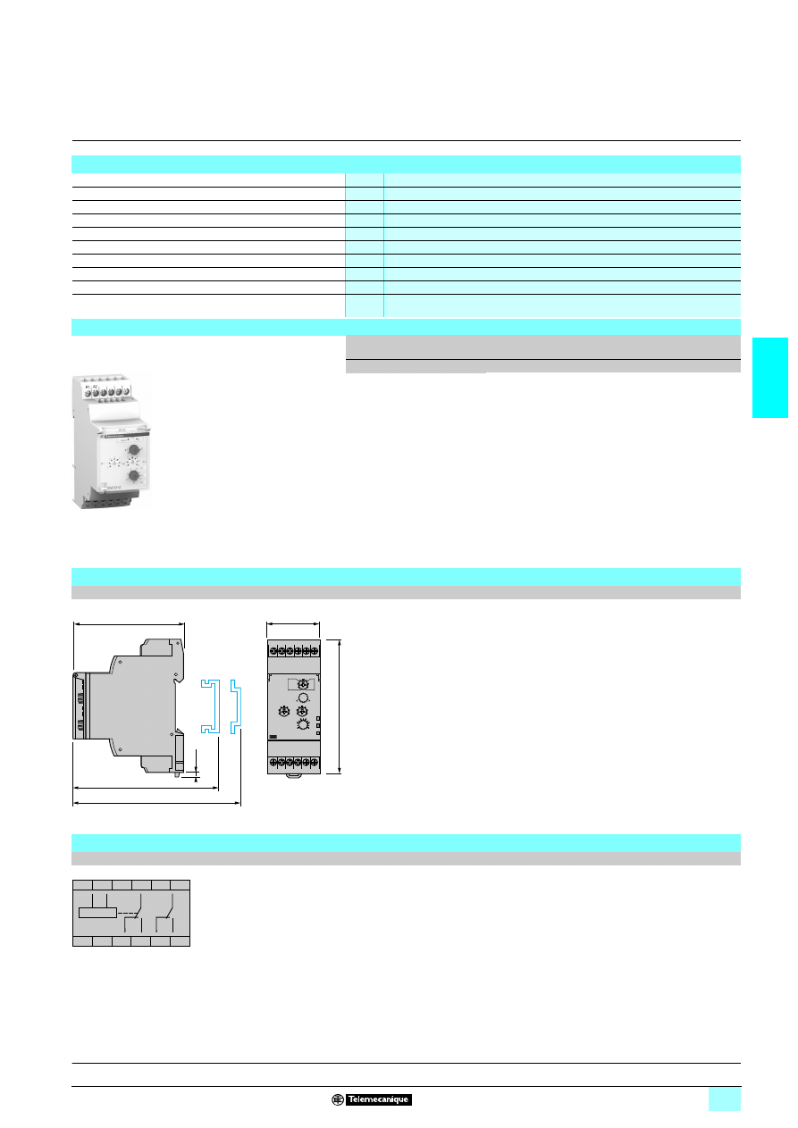
3/73
3
Characteristics
(continued),
reference,
dimensions,
scheme
3
Zelio Control
-
modular measurement
and control relays
3
Frequency control relay
RM35 HZ
Output characteristics
Output type
1 C/O + 1 C/O contacts
Contact type
Cadmium-free
Nominal current
A
5
Maximum switching voltage
V
1/2 250
Rated breaking capacity
VA
1250
Minimum breaking current
mA
10/
2 5 V
Electrical durability
1 x 10
5
operating cycles
Mechanical durability
30 x 10
6
operating cycles
Maximum operating rate
360 operations/hour under full load
Utilisation categories
Conforming to IEC 60947-5-1
AC-12, AC-13, AC-14, AC-15, DC-12, DC-13, DC-14
Reference
Function
Range
controlled
Supply
voltage
Output
Reference
Weight
V
kg
5 Over-frequency
and under-
frequency
50 or 60 Hz
40…60 Hz
(50 Hz) /
50…70 Hz
(60 Hz)
1 120…277
1 C/O + 1 C/O
5 A
RM35 HZ21FM
0.130
Dimensions
RM35 HZ21FM
mm/In.
Scheme
RM35 HZ21FM
RM35 HZ21FM
10
56
84
A1
12
22
14
21 24
11
A2
90/
3.54
35/
1.38
2,8
0.11
76/
2.99
72,5/
2.85
72/
2.83
A1
A2
11
12
14
22
21
24
A1
A2
21
11
12
14
24
22
R1
R2
Presentation, description :
page 3/70
Operation:
page 3/71
Characteristics:
pages 3/72 and 3/73
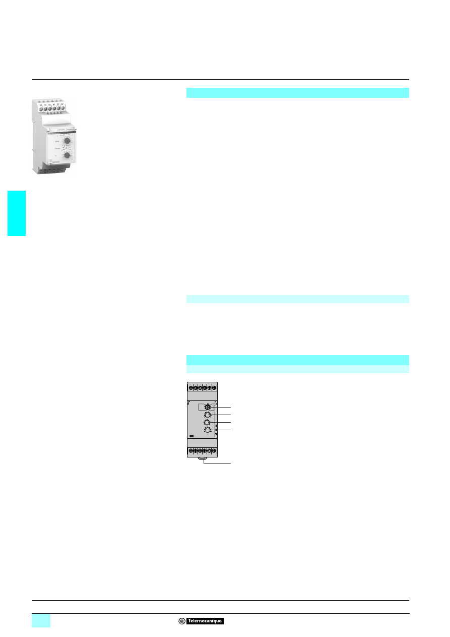
3/74
3
Presentation,
description
3
Zelio Control
-
modular measurement
and control relays
3
Speed control relays RM35 S
Presentation
Speed control relay RM35 S0MW monitors:
1 Underspeed:
2 without memory,
2 with memory,
2 with inhibition by external contact S2.
1 Overspeed:
2 without memory,
2 with memory,
2 with inhibition by external contact S2.
Speed control relay RM35 S0MW measures via:
1 A 3-wire PNP or NPN proximity sensor input,
1 A Namur proximity sensor input,
1 A 0-30 V voltage input,
1 A volt-free contact input.
It operates with either
N/O
or
N/C
sensors.
The adjustable time between impulses is 0.05 s…10 min.
The power-on inhibition time is adjustable from 0.6 to 60 s.
Inhibition is controlled by an external contact.
Settings are protected by a sealable cover.
Control status is indicated by a LED.
The relay is designed for clip-on mounting on
5 rail
Applications
1 Monitors speed or rate of rotary or linear movements in the following applications:
2 conveyors/conveyor belts,
2 packaging,
2 mechanical handling.
Description
RM35 S00MW
1
Configuration: selection of operating mode:
Underspeed or overspeed.
Underspeed/Overspeed
with or without memory. Memory - No Memory
2
Speed threshold setting potentiometer. Value
3
Speed range selector switch
4
Starting inhibition time delay adjustment
potentiometer. Ti
5
Spring for clip-on mounting on 35 mm
5 rail.
In
Yellow LED: indicates inhibition status (time-delay or S2 input).
Un Green LED: indicates that supply to the relay is on.
R
Yellow LED: indicates relay output state.
RM35 S0MW
10
56
87
Y1
A1
12 11 14
A2
12V12V E1 E2 0V
R
Un
In
1
2
3
4
5
Operation:
pages 3/75 and 3/76
Characteristics:
pages 3/77 and 3/78
References, dimensions :
page 3/79
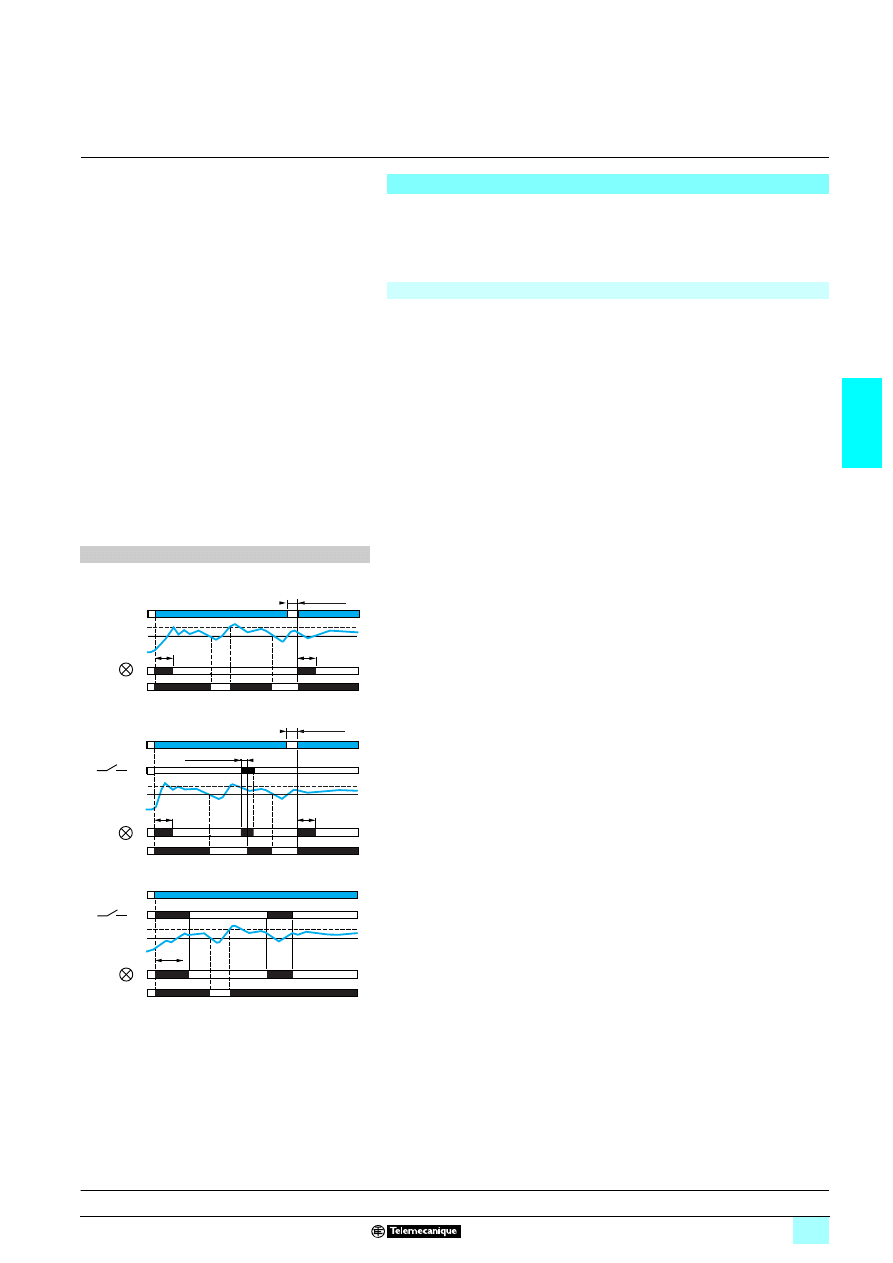
3/75
3
Operation
3
Zelio Control
-
modular measurement
and control relays
3
Speed control relays RM35 S
Operating principle
Relay RM35 S0MW monitors the speed (rate, frequency) of a process (conveyor,
conveyor belt, etc.) via discrete sensors:
3-wire PNP or NPN proximity sensor, or 0-30 V voltage input, or NAMUR proximity
sensor, or volt-free contact.
It can be used for monitoring underspeed or overspeed.
Speed control relay: RM35 S0MW
2222 Measurement
The cycle of the process being monitored is the series of impulses characterised by
a two-state signal: high and low. The speed measurement is obtained by measuring
the period of this signal, from the first change of state detected (either rising or falling
edge).
Digital processing of the signal allows the disparity between the signals to be
calculated.
At power up, or after appearance (or reappearance) of the sensor signal, detection
(characterisation) of the signal requires processing of one or more periods
(maximum of two). During this time, control is inoperative.
1 Operating mode
Using the switch, select one of the four operating modes:
2 Underspeed without memory,
2 Underspeed with memory,
2 Overspeed without memory,
2 Overspeed with memory.
Function diagrams
2222 Underspeed control
1 Function: Underspeed control - Underspeed
2 Without memory - No Memory
At the end of the starting inhibition time delay "Ti", as soon as the speed measured
drops below the threshold setting, the output relay changes state from "closed" to
"open".
It returns to its initial state when the speed is again higher than the threshold plus
hysteresis (fixed at 5% of the threshold setting).
When power is restored, after a break having lasted at least 1 s, the relay is in the on
("normal") state during the time delay and stays in that state for as long as the speed
remains higher than the threshold.
2 With memory Memory
When relay RM35 S has been configured in "memory" mode, if underspeed is
detected, the output relay stays in the off ("alarm") state whatever the further
evolution of the process speed.
It will not be able to return to the on ("normal") state until contact S2 closes (for at
least 50 ms).
If, when S2 re-opens, the speed is not high enough, the relay returns to the locked,
off ("alarm") state.
Relay RM35 S can also be reset by a power break (at least 1 s); the relay then
returns to the on ("normal") state for at least the duration of the time delay, whatever
the process speed.
2 With inhibition by S2 - Inhib./S2
At power up, in order to allow the process being monitored to reach its nominal
operating speed, relay RM35 S is inhibited for a time delay adjustable from
0.6…60 s. This time delay can be adjusted (shortened or lengthened) during
inhibition.
Relay RM35 S can also be inhibited by closing of contact S2: on starting, for
example, if the process run up to speed time is greater than 60 s, or at any time
during operation.
Whether it results from a starting inhibition time delay or closing of S2, inhibition
keeps the output relay in the "closed" position and is signalled by illumination of the
inhibition LED.
If, after lifting of inhibition (end of starting inhibition time delay or opening of contact
S2), the signal detection phase has not been completed, the relay drops out after the
set wait time between two impulses (measured as from the end of inhibition).
Inhibition must last as long as is necessary for the product to detect at least 2 periods.
When the signal has not been 'characterised' by the end of the inhibition period, the
"inhibition" LED flashes for as long as speed measurement is impossible.
It is also possible to inhibit relay RM35 S at any time, during operation, by closing S2.
V
Vs
Ti Ti
1 sec mini
In
11-12/11-14
Supply Un
Relays
Hysteresis
Threshold
1 sec mini
50 ms mini
V
S2
Ti
Ti
Vs
In
11-12/11-14
Supply Un
Relays
Hysteresis
Threshold
Ti
V
S2
Vs
In
11-12/11-14
Supply Un
Relays
Hysteresis
Threshold
Presentation, description :
page 3/74
Characteristics:
pages 3/77 and 3/78
References, dimensions :
page 3/79
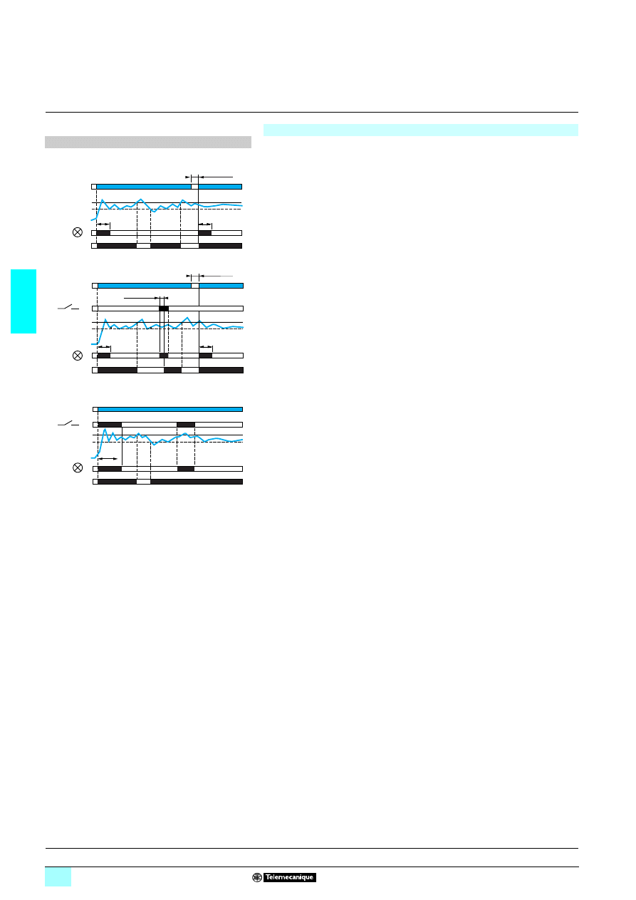
3/76
3
Operation
(continued)
3
Zelio Control
-
modular measurement
and control relays
3
Speed control relays RM35 S
Speed control relay: RM35 S0MW (continued)
Function diagrams
2222 Overspeed control
1 Function: overspeed control - Overspeed
2 Without memory- No Memory
At the end of the starting inhibition time delay, "Ti", as soon as the speed measured
is higher than the threshold setting, the output relay changes state from "closed" to
"open".
It returns to its initial state when the speed is again lower than the threshold minus
hysteresis (fixed at 5% of the threshold setting).
When power is restored to relay RM35 S, after a break having lasted at least 1 s, the
relay is in the on ("normal") state during the time delay and stays in that state for as
long as the speed remains lower than the threshold.
2 With memory - Memory
When relay RM35 S has been configured in "memory" mode, if overspeed is
detected, the output relay stays in the off ("alarm") state whatever the further
evolution of the process speed.
It will not be able to return to the on ("normal") state until contact S2 closes (for at
least 50 ms).
If, when S2 re-opens, the speed is too high, the relay returns to the locked off
("alarm") state.
Relay RM35 S can also be reset by a power break (at least 1 s); the relay then
returns to the on ("normal") state for at least the duration of the time delay, whatever
the process speed.
2 With inhibition by S2. - Inhib./S2
At power up, in order to allow the process being monitored to reach its nominal
operating speed, relay RM35 S is inhibited for a time delay adjustable from
0.6…60 s. This time delay can be modified (shortened or lengthened) during
inhibition.
Relay RM35 S can also be inhibited by closing of contact S2: on starting, for
example, if the process run up to speed time is greater than 60 s, or at any time
during operation.
Whether it results from a starting inhibition time delay or closing of S2, inhibition
keeps the output relay in the "closed" position and is signalled by illumination of the
inhibition LED.
If, after lifting of inhibition (end of starting inhibition time delay or opening of contact
S2), the signal detection phase has not been completed, the relay drops out after the
set wait time between two impulses (measured as from the end of inhibition).
Inhibition must last as long as is necessary for the product to detect at least 2 periods.
When the signal has not been 'characterised' by the end of the inhibition period, the
"inhibition" LED flashes for as long as speed measurement is impossible.
It is also possible to inhibit relay RM35 S at any time, during operation, by closing S2.
V
Ti
Ti
1 sec mini
In
11-12/11-14
Vs
Supply Un
Relays
Hysteresis
Threshold
V
1 sec mini
50 ms mini
Ti
Ti
S2
Vs
In
11-12/11-14
Supply Un
Relays
Hysteresis
Threshold
Ti
V
S2
Vs
In
11-12/11-14
Supply Un
Relays
Hysteresis
Threshold
Presentation, description :
page 3/74
Characteristics:
pages 3/77 and 3/78
References, dimensions :
page 3/79
3/77
3
Characteristics
3
Zelio Control
-
modular measurement
and control relays
3
Speed control relays RM35 S
Environment characteristics
Conforming to standards
NF EN 60255-6 and IEC 60255-6
Product certifications
Pending
UL, CSA, GL, C-Tick, GOST
Marking
1
1
1
1: 73/23/EEC and EMC 89/336/EEC
Ambient air temperature
around the device
Storage
°C
- 40…+ 70
Operation
°C
- 20…+ 50
Permissible relative humidity Conforming to IEC 60068-2-30
2 x 24 hours…+ 95 % RH at + 55 °C (without condensation)
Vibration resistance
Conforming to IEC 60068-2-6
0.035 mm from 10…150 Hz
Shock resistance
Conforming to IEC 60068-2-6
5 gn
Degree of protection
Conforming to IEC 60529
Casing
IP 30
Terminals
IP 20
Degree of pollution
Conforming to IEC 60664-1
3
Overvoltage category
Conforming to IEC 60664-1
III
Insulation resistance
Conforming to
IEC 60664-1, 60255-5
> 500 M
Ω,
2 500 V
Rated insulation voltage
Conforming to IEC 60664-1
V
250
Insulation test voltage
Dielectric test
kV
2,
1 50 Hz, 1 min.
Shock wave
kV
4
Mounting position
without derating
In relation to normal vertical
mounting plane
Any position
Connection
Maximum c.s.a.
Conforming to IEC3 60947-1
Solid cable without cable end
mm
2
1 conductor: 0.5…4 (AWG 20…AWG 11)
2 conductors: 0.5…2.5 (AWG 20…AWG 14)
Flexible cable with cable end
mm
2
1 conductor: 0.2…2.5 (AWG 24…AWG 12)
2 conductors: 0.2…1.5 (AWG 24…AWG 16)
Tightening torque
Conforming to IEC 60947-1
0.6…1 N.m / 5.3…8.8 Lbf.In
Housing material
Self-extinguishing plastic
Power ON indicator
Green LED
Relay state indicator (R)
Yellow LED
Inhibit status indication
Yellow LED
Mounting
Conforming to IEC/EN 60715
On 35 mm
3 rail
Supply characteristics
Rated supply voltage Un
V
1/2 24…240
Operating range
V
1/2 20.4…264
Polarity on d.c. supply
No
Voltage limits
Of the power supply circuit
- 15 %, + 10 %
Frequency
Of the power supply circuit
50/60 Hz ± 10 %
Galvanic isolation, supply/measurement
Yes
Maximum power consumption
1 5 VA and 2 3 W
Immunity to microbreaks
ms
50
Sensor supply characteristics
Nominal voltage
V
12 ± 0,5
Available current
mA
50 for
1/2424 V 8 Un 8 1/24240 V
40 for Un <
1/2424 V at 25 °C
Immunity to electromagnetic interference
Electromagnetic compatibility
Immunity NF EN 61000-6-2 / IEC 61000-6-2
Emission NF EN 61000-6-4,
NF EN 61000-6-3,
IEC 61000-6-4,
IEC 61000-6-3
Presentation, description :
page 3/74
Operation:
pages 3/75 and 3/76
References, dimensions :
page 3/79
3/78
3
Characteristics
(continued)
3
Zelio Control
-
modular measurement
and control relays
3
Speed control relays RM35 S
Measurement circuit and input characteristics
Input circuit
3-wire sensor (E1)
PNP or NPN, 12 V, 50 mA max
NAMUR sensor (E2)
12 V, 1.5 k
Ω
Volt-free contact input (E1)
12 V, 9.5 k
Ω
Voltage input (E1)
Voltage range: 0 V min, 30 V max
Input resistance: 9.5 k
Ω
High state: 4.5 V min
Low state: 1 V max
Minimum impulse time
At high state
ms
5
At low state
ms
5
Measurement range
0.05…0.5 s
0.1…1 s
0.5…5 s
1…10 s
0.1…1 min
0.5…5 min
1…10 min
Threshold setting
10…100 % of the range
Fixed hysteresis
5 % of the threshold setting
Setting accuracy
± 10 % of the full scale value
Repeat accuracy (with constant parameters)
± 0.5 %
Measurement error with voltage variation
< 1 % over the whole range
Measurement error with temperature variation
± 0,1 % / °C max
Frequency of input signals
Hz
1.7 mHz min, 20 Hz max
Time delay characteristics
Response time on crossing the threshold
ms
15 max
Repeat accuracy (with constant parameters)
± 0.5 %
Reset time in memory mode
Contact S2
ms
50 minimum
Supply Un
s
1
Inhibition time delay
On energisation
0.6…60 s +10 % of the full scale value
Delay on pick-up
ms
50
Output characteristics
Output type
1 C/O contact
Contact type
Cadmium-free
Nominal current
A
5
Maximum switching voltage
V
1/2 250
Rated breaking capacity
VA
1250
Minimum breaking current
mA
10/
2 5 V
Electrical durability
1 x 10
5
operating cycles
Mechanical durability
30 x 10
6
operating cycles
Maximum operating rate
360 operations/hour under full load
Utilisation categories
Conforming to IEC 60947-5-1
AC-12, AC-13, AC-14, AC-15, DC-12, DC-13, DC-14
Presentation, description :
page 3/74
Operation:
pages 3/75 and 3/76
References, dimensions :
page 3/79
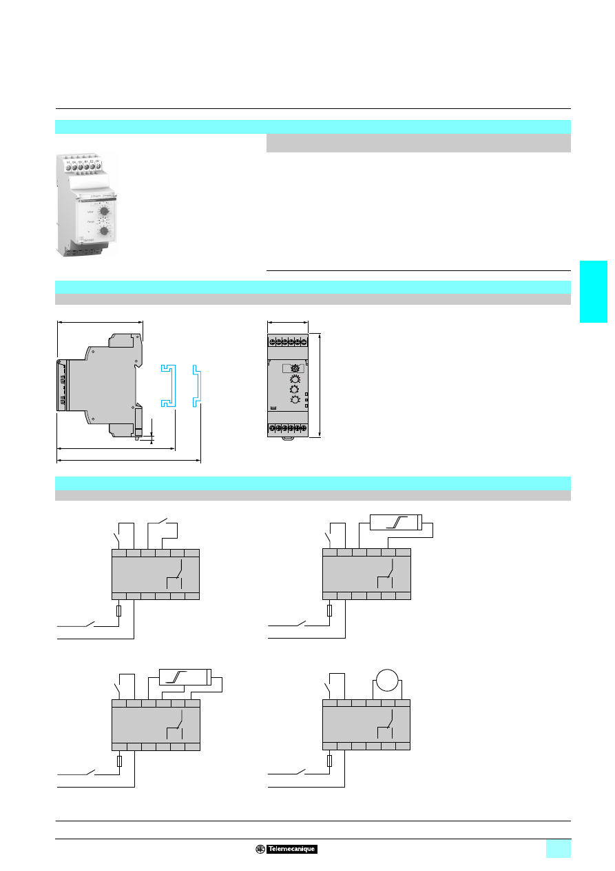
3/79
3
Reference,
dimensions,
schemes
3
Zelio Control
-
modular measurement
and control relays
3
Speed control relays RM35 S
Reference
Function
Supply
V
Measurement
Input
Output
Reference
Weight
kg
5 Underspeed,
5 Overspeed
1/2 24…240 5 3-wire
PNP or NPN
proximity sensor
(1),
5 Namur proximity
sensor,
5 0-30 V voltage,
5 Volt-free contact.
1 C/O
5 A
RM35 S0MW
0.130
(1) See page 3/80.
Dimensions
RM35 S0MW
mm/In.
Schemes
RM35 S0MW
Contact input
Namur proximity sensor input
NPN/PNP sensor input
0-30 V voltage input
(2) A quick-blow fuse or circuit-breaker.
RM35 S0MW
10
56
87
2,8
0.11
76/
2.99
72,5/
2.85
72/
2.83
90/
3.54
35/
1.38
11
12
14
11
12
14
A1
A2
Y1 12 V
S2
Inhib. - Reset
R
S1
12 V E1
E2 0 V
+/–
–/+
z 24...240 V
50/60 Hz
F1
(2)
S2
Inhib. - Reset
11
12
14
11
12
14
A1
A2
Y1 12 V
R
S1
12 V E1
E2 0 V
+/–
+
–
–/+
z 24...240 V
50/60 Hz
F1
(2)
S2
Inhib. - Reset
11
12
14
11
12
14
A1
A2
Y1 12 V
R
S1
12 V E1
E2 0 V
+/–
–/+
z 24...240 V
50/60 Hz
B
BU
BK
F1
(2)
S2
Inhib. - Reset
11
12
14
11
12
14
A1
A2
Y1 12 V
R
S1
12 V E1
E2 0 V
+/–
–
+
–/+
z 24...240 V
50/60 Hz
e
F1
(2)
Presentation, description :
page 3/74
Operation:
pages 3/75 and 3/76
Characteristics:
pages 3/77 and 3/78
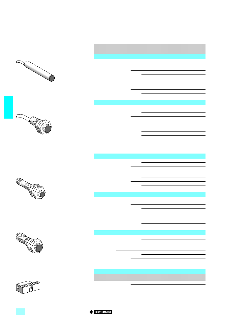
3/80
3
References
3
Inductive proximity sensors
3
Osiprox
®
Optimum
(1)
Cylindrical, flush mountable, increased range
Three-wire, d.c. supply, solid-state output
Sensing
distance Sn
(mm)
Function
Output Connection
Reference
Weight
kg
Ø 6 plain
2.5
NO
PNP
Pre-cabled (L = 2 m)
XS1 L06PA349
0.025
M8 connector
XS1 L06PA349S
0.010
M12 connector
XS1 L06PA349D
0.015
NPN
Pre-cabled (L = 2 m)
XS1 L06NA349
0.025
M8 connector
XS1 L06NA349S
0.010
M12 connector
XS1 L06NA349D
0.015
NC
PNP
Pre-cabled (L = 2 m)
XS1 L06PB349
0.025
M8 connector
XS1 L06PB349S
0.010
NPN
Pre-cabled (L = 2 m)
XS1 L06NB349
0.025
M8 connector
XS1 L06NB349S
0.010
Ø 8, threaded M8 x 1
2.5
NO
PNP
Pre-cabled (L = 2 m)
XS1 N08PA349
0.035
M8 connector
XS1 N08PA349S
0.015
M12 connector
XS1 N08PA349D
0.020
NPN
Pre-cabled (L = 2 m)
XS1 N08NA349
0.035
M8 connector
XS1 N08NA349S
0.015
M12 connector
XS1 N08NA349D
0.020
NC
PNP
Pre-cabled (L = 2 m)
XS1 N08PB349
0.035
M8 connector
XS1 N08PB349S
0.015
M12 connector
XS1 N08PB349D
0.020
NPN
Pre-cabled (L = 2 m)
XS1 N08NB349
0.035
M8 connector
XS1 N08NB349S
0.015
M12 connector
XS1 N08NB349D
0.020
Ø 12, threaded M12 x 1
4
NO
PNP
Pre-cabled (L = 2 m)
XS1 N12PA349
0.070
M12 connector
XS1 N12PA349D
0.020
NPN
Pre-cabled (L = 2 m)
XS1 N12NA349
0.070
M12 connector
XS1 N12NA349D
0.020
NC
PNP
Pre-cabled (L = 2 m)
XS1 N12PB349
0.070
M12 connector
XS1 N12PB349D
0.020
NPN
Pre-cabled (L = 2 m)
XS1 N12NB349
0.070
M12 connector
XS1 N12NB349D
0.020
Ø 18, threaded M18 x 1
10
NO
PNP
Pre-cabled (L = 2 m)
XS1 N18PA349
0.100
M12 connector
XS1 N18PA349D
0.040
NPN
Pre-cabled (L = 2 m)
XS1 N18NA349
0.100
M12 connector
XS1 N18NA349D
0.040
NC
PNP
Pre-cabled (L = 2 m)
XS1 N18PB349
0.100
M12 connector
XS1 N18PB349D
0.040
NPN
Pre-cabled (L = 2 m)
XS1 N18NB349
0.100
M12 connector
XS1 N18NB349D
0.040
Ø 30, threaded M30 x 1.5
20
NO
PNP
Pre-cabled (L = 2 m)
XS1 N30PA349
0.160
M12 connector
XS1 N30PA349D
0.100
NPN
Pre-cabled (L = 2 m)
XS1 N30NA349
0.160
M12 connector
XS1 N30NA349D
0.100
NC
PNP
Pre-cabled (L = 2 m)
XS1 N30PB349
0.160
M12 connector
XS1 N30PB349D
0.100
NPN
Pre-cabled (L = 2 m)
XS1 N30NB349
0.160
M12 connector
XS1 N30NB349D
0.100
Accessories
Description
mm
Reference
Weight
kg
Fixing clamps
Ø 8
XSZ B108
0.006
Ø 12
XSZ B112
0.006
Ø 18
XSZ B118
0.010
Ø 30
XSZ B130
0.020
(1) Accessories recommended for RM35 S0MW control relays
80
11
20
XS1 L06
1A349
80
12
31
XS1 N
1111349
80
11
67
XS1 N08
11349S
801
23
2
XS1 N
1111349D
XSZ B1
11
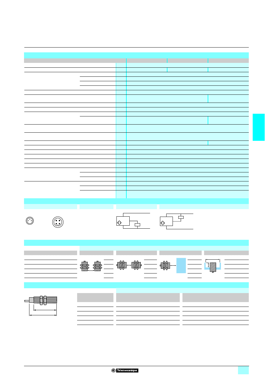
3/81
3
Characteristics,
schemes,
setting-up,
dimensions
3
Inductive proximity sensors
3
Osiprox
®
Optimum
Cylindrical, flush mountable, increased range
Three-wire, d.c. supply, solid-state output
Characteristics
Sensor type
XS1
22222
22222
22222
22222349D
XS1
22222
22222
22222
22222349S
XS1
22222
22222
22222
22222349
Product certifications
UL, CSA,
6
Connection
M12 connector
M8 connector
Pre-cabled, length: 2 m
Operating zone
Ø 6.5 and Ø 8
mm
0…2
Ø 12
mm
0…3.2
Ø 18
mm
0…8
Ø 30
mm
0…16
Differential travel
%
1...15 of real sensing distance (Sr)
Degree of protection
Conforming to IEC 60529
IP 67
IP 68, double insulation
(except Ø 6.5 and Ø 8: IP 67)
Storage temperature
°C
- 40…+ 85
Operating temperature
°C
- 25…+ 50
Materials
Case
Nickel plated brass
Cable
–
PvR 3 x 0.34 mm
2
except
Ø 6.5 and Ø 8: 3 x 0.11 mm
2
Vibration resistance
Conforming to
IEC 60068-2-6
25 gn, amplitude ± 2 mm (f = 10 to 55 Hz)
Shock resistance
Conforming to
IEC 60068-2-27
50 gn, duration 11 ms
Output state indication
Yellow LED, 4 viewing ports at 90°
Yellow LED, annular
Rated supply voltage
V
2 12…24 with protection against reverse polarity
Voltage limits (including ripple)
V
2 10…36
Switching capacity
mA
8 200 with overload and short-circuit protection
Voltage drop, closed state
V
8 2
Current consumption, no-load
mA
8 10
Maximum switching frequency
Ø 6.5, Ø 8 and Ø 12
Hz
2500
Ø 18
Hz
1000
Ø 30
Hz
500
Delays
First-up
ms
8 5
Response
ms
8 0.2 for Ø 8 and Ø 12, 8 0.3 for Ø 18, 8 0.6 for Ø 30
Recovery
ms
8 0.2 for Ø 8 and Ø 12, 8 0.7 for Ø 18, 8 1.4 for Ø 30
Wiring schemes
Connector
Pre-cabled
PNP 3-wire
NPN 3-wire
M8
M12
BU: Blue
BN: Brown
BK: Black
Setting-up
Minimum mounting distances (mm)
Sensor
Side by side
Face to face
Facing a metal object
Mounted in a metal support
Ø 6.5
e
1 5
e
1 30
e
1 7.5
d
1 10 h 1 1.6
Ø 8
e
1 5
e
1 30
e
1 7.5
d
1 10 h 1 1.6
Ø 12
e
1 8
e
1 48
e
1 12
d
1 14 h 1 2.4
Ø 18
e
1 20
e
1 96
e
1 30
d
1 28 h 1 3.6
Ø 30
e
1 40
e
1 240
e
1 60
d
1 50 h 1 6
Dimensions
Flush mountable in metal
Sensor
Pre-cabled
M8 connector
M12 connector
a
b
a
b
a
b
Ø 6.5
33
30
42
34
45
24
Ø 8
33
25
42
26
45
23
Ø 12
33
25
–
–
48
29
Ø 18
36.5
28
–
–
48.6
28
Ø 30
40.6
32
–
–
52.7
32
1
3
4
1
2
4
3
–
BN/1
BU/3
+
PNP
BK/4 (NO)
BK/2 (NC)
BN/1
BU/3
+
–
BK/4 (NO)
BK/2 (NC)
NPN
e
e
e
h
d
a
b
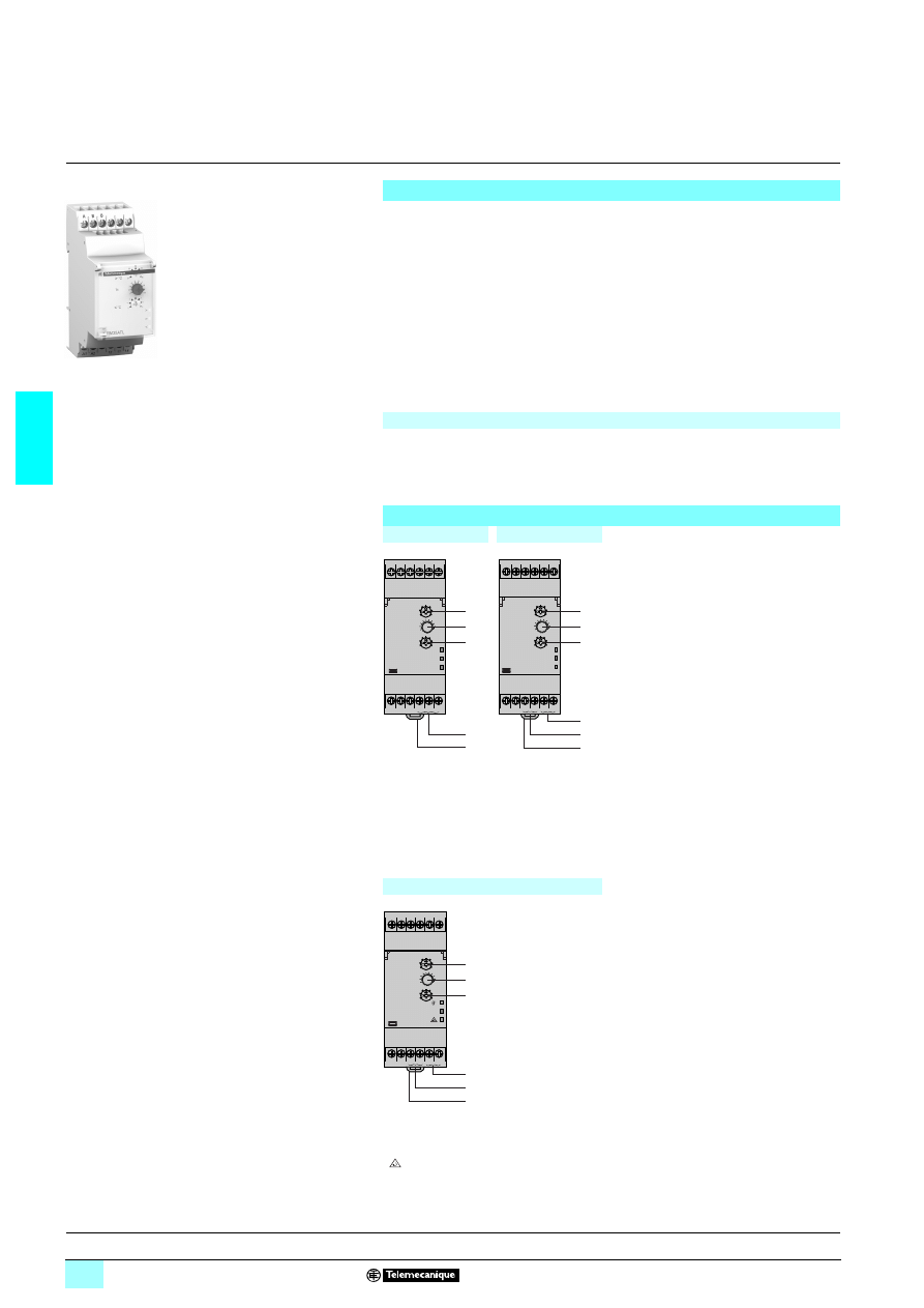
3/82
3
Presentation,
description
3
Zelio Control
-
modular measurement
and control relays
3
Temperature control relays RM35 AT
1 for
elevator machine rooms and 3-phase supplies
Presentation
Measurement and control relays RM35 ATL0MW, RM35 ATR5MW and
RM35 ATW5MW are designed for monitoring the temperature in elevator machine
rooms, in compliance with directive EN81.
1 PT 100 input,
1 Adjustable control around 5 °C and 40 °C,
1 Independent adjustment of high and low thresholds,
1 Possibility of integrated phase control,
Settings are protected by a sealable cover.
Control status is indicated by a LED.
The relays are designed for clip-on mounting on
5 rail.
Applications
1 Temperature control for elevator machine rooms.
Description
RM35 ATL0MW
RM35 ATR5MW
1
High temperature threshold setting
potentiometer.
θ
>
2
Potentiometer for adjustment of time
delay on crossing of temperature
threshold. Tt
3
Low temperature threshold setting
potentiometer.
θ
<
4
Spring for clip-on mounting on 35 mm
5 rail.
5
High temperature threshold contact
(11-14).
6
Low temperature threshold contact
(21-24).
7
High and low temperature threshold
contacts.
>
Yellow LED: indicates relay output state (high temperature threshold).
Un
Green LED: indicates that supply to the relay is on.
<
Yellow LED: indicates relay output state (low temperature threshold).
RM35 ATW5MW
1
High temperature threshold setting
potentiometer.
θ
>
2
Potentiometer for adjustment of time
delay on crossing of temperature
threshold. Tt
3
Low temperature threshold setting
potentiometer.
θ
<
4
Spring for clip-on mounting on 35 mm
5 rail.
5
Temperature relay contact (11-14).
6
Phase relay contact (21-44).
<
θ
°
<
Yellow LED: indicates temperature relay output state. R1
Un
Green LED: indicates that supply to the relay is on.
Yellow LED: indicates phase relay output state. R2
RM35 AT
10MW
10
56
88
4
A
A1
12 11 14
A2
B
B
>
<
Un
1
2
3
7
A
A1
14
11
21 24
A2
B
B
>
<
Un
1
2
3
4
5
6
A
L1 L2 L3
A1
14
11
21 24
A2
B
B
Un
L1
L2
L3
<
<
1
2
3
4
5
6
L1
L2
L3
Operation:
page 3/83
Characteristics:
pages 3/84 and 3/85
References, dimensions :
page 3/85
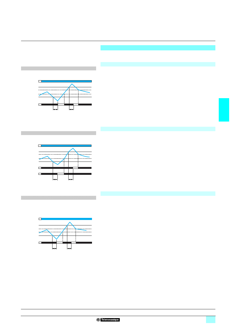
3/83
3
Operation
3
Zelio Control
-
modular measurement
and control relays
3
Temperature control relays RM35 AT
1 for
elevator machine rooms and 3-phase supplies
Operating principle
Temperature control relays for elevator machine rooms are designed to monitor the
said temperature between 5°C and 40°C in compliance with directive EN81.
Temperature control relay: RM35 ATL0MW
After a delay on pick-up after energisation, and for as long as the temperature
monitored by the PT100 probe remains between the two thresholds set on the front
panel, the output relay is closed and the yellow LEDs are on.
When the temperature crosses one of the threshold settings on the front panel (high
or low threshold), the time delay set on the front panel (Tt) is activated. The yellow
LED corresponding to the threshold crossed (low or high), flashes.
At the end of the time delay, if the temperature is still outside the threshold setting,
the output relay opens and the yellow LED corresponding to the threshold crossed
goes out.
The output relay closes instantly (within the response time on disappearance of a
fault) when the temperature returns within the window of the two threshold settings
on the front panel, plus the fixed hysteresis.
If the PT 100 probe is incorrectly wired (missing or short-circuited) the relay is open
and the 3 LEDs flash.
Temperature control relay: RM35 ATR5MW
After a delay on pick-up after energisation, and for as long as the temperature
monitored by the PT100 probe remains between the two threshold settings on the
front panel, the output relays are closed and their yellow LEDs are on.
When the temperature crosses one of the threshold settings on the front panel (high
or low threshold), the time delay set on the front panel (Tt) is activated. The yellow
LED corresponding to the threshold crossed (low or high), flashes.
At the end of the time delay, if the temperature is still outside one of the threshold
settings, the corresponding output relay opens and the yellow LED corresponding to
the threshold crossed goes out.
The output relay closes instantly (response time on disappearance of a fault) when
the temperature returns within the window of the two threshold settings on the front
panel, plus (or minus) the fixed hysteresis.
If the PT 100 probe is incorrectly wired (missing or short-circuited) the relays are
open and the 3 LEDs flash.
Temperature and phase control relay: RM35 ATW5MW
After a delay on pick-up after energisation, and for as long as the temperature
monitored by the PT100 probe remains between the two threshold settings on the
front panel, the temperature relay R1 is closed.
When the temperature crosses one of the threshold settings on the front panel (high
or low threshold), the time delay set on the front panel (Tt) is activated. The yellow
temperature LED flashes. At the end of the time delay, if the temperature is still
outside the threshold setting, the output relay R1 opens and the yellow LED goes out.
The output relay R1 closes instantly when the temperature returns to within the
window of the two threshold settings on the front panel, plus or minus the fixed
hysteresis.
The device also monitors the correct sequence of phases L1, L2 and L3 of the
3-phase supply and total phase failure, even in the case of phase regeneration
(< 70 %).
After a delay on pick-up after energisation, and for as long as phase presence and
phase sequence are correct, relay R2 and the "phase" LED are On. When a fault
appears, the "phase" relay opens and the "phase" LED instantly goes out (response
time on appearance of a fault).
When the fault disappears, the phase control relay and LED are activated (response
time on disappearance of a fault).
If the PT 100 probe is incorrectly wired (missing or short-circuited) relay R1 is open
and LED R1 flashes.
Function diagram
1 Function:
2 Temperature control by PT 100 probe.
Tt: Time delay after crossing of the temperature threshold
(adjustable on front panel).
11-12
>
<
Tt
Tt
θ°
θ°
θ
°
11-14
Relays
Hysteresis
Supply Un
Hysteresis
Function diagram
1 Function
2 Temperature control by PT 100 probe.
Tt: Time delay after crossing of the temperature threshold
(adjustable on front panel).
11-14
21-24
Tt
Tt
>
<
θ°
θ°
θ
°
Relay R1
Hysteresis
Supply Un
Hysteresis
Relay R2
Function diagram
1 Function
2 Temperature control by PT 100 probe
2 Sequence of phases L1, L2, L3.
2 Phase failure.
Tt: Time delay after crossing of the temperature threshold
(adjustable on front panel).
11-14
Tt
Tt
>
<
θ°
θ°
θ
°
Relay R1
Hysteresis
Supply Un
Hysteresis
Presentation, description :
page 3/82
Characteristics:
pages 3/84 and 3/85
References, dimensions :
page 3/85

3/84
3
Characteristics
3
Zelio Control
-
modular measurement
and control relays
3
Temperature control relays RM35 AT
1 for
elevator machine rooms and 3-phase supplies
Environment characteristics
Relay type
RM35 ATL0MW
RM35 ATR5MW
RM35 ATW5MW
Conforming to standards
NF EN 60255-6 and IEC 60255-6
Product certifications
Pending
UL, CSA, GL, C-Tick, GOST
Marking
1
1
1
1: 73/23/EEC and EMC 89/336/EEC
Ambient air temperature
around the device
Storage
°C
- 40…+ 70
Operation
°C
- 20…+ 50
Permissible relative humidity Conforming to IEC 60068-2-30
2 x 24 hours…+ 95 % RH at + 55 °C (without condensation)
Vibration resistance
Conforming to IEC 60068-2-6
0.035 mm from 10…150 Hz
Shock resistance
Conforming to IEC 60068-2-6
5 gn
Degree of protection
Conforming to IEC 60529
Casing
IP 30
Terminals
IP 20
Degree of pollution
Conforming to IEC 60664-1
3
Overvoltage category
Conforming to IEC 60664-1
III
Insulation resistance
Conforming to 60664-1/60255-5
> 100 M
Ω,
2 500 V
Rated insulation voltage
Conforming to IEC 60664-1
V
250
250
400
Insulation test voltage
Dielectric test
kV
2,
1 50 Hz, 1 min.
Shock wave
kV
4
Mounting position
without derating
In relation to normal
vertical mounting plane
Any position
Connection
Maximum c.s.a.
Conforming to IEC 60947-1
Solid cable without cable end
mm
2
1 conductor: 0.5…4 (AWG 20…AWG 11)
2 conductors: 0.5…2.5 (AWG 20…AWG 14)
Flexible cable with cable end
mm
2
1 conductor: 0.2…2.5 (AWG 24…AWG 12)
2 conductors: 0.2…1.5 (AWG 24…AWG 16)
Tightening torque
Conforming to IEC 60947-1
0.6…1 N.m / 5.3…8.8 Lbf.In
Housing material
Self-extinguishing plastic
Power ON indicator
Green LED
Green LED
Green LED
Relay state indicator
High threshold
Yellow LED
Yellow LED
–
Low threshold
Yellow LED
Yellow LED
–
High threshold/low threshold
–
–
Yellow LED
Phases
–
–
Yellow LED
Mounting
Conforming to IEC/EN 60715
On 35 mm
3 rail
Supply characteristics
Relay type
RM35 ATL0MW
RM35 ATR5MW
RM35 ATW5MW
Rated supply voltage Un
V
1/2 24…240
Operating range
V
1 20.4…264
2 21.6…264
Voltage limits
Of the power supply circuit
1 - 15 %, + 10 %
2 - 10 %, + 10 %
Frequency
Of the power supply circuit
Hz
50/60 Hz ± 10 %
Galvanic isolation, supply/measurement
Yes
No
Maximum power consumption at Un
VA
143.5
W
2 0.6
Immunity to microbreaks
ms
10
Immunity to electromagnetic interference
Electromagnetic compatibility
Immunity NF EN 61000-6-2 / IEC 61000-6-2
Emission NF EN 61000-6-4
NF EN61000-6-3 , IEC 61000-6-4, IEC 61000-6-3
Measurement circuit and input characteristics
Measurement range
Low temperature
°C
- 1, 1, 3, 5, 7, 9, 11
High temperature
°C
34, 36, 38, 40, 42, 44, 46
Temperature sensor
PT 100 - 3-wire
Phase measurement range
V
–
–
208…480, - 15 %/+ 10 %
Frequency of the measured signal
Hz
–
–
50…60 ± 1
Detection of phase failure with regeneration
–
–
> 30 % of the average of the
3 phases
Input resistance
Temperature
Ω
1330
3-phase
k
Ω
–
–
600
Setting accuracy
°C
± 2
Maximum length of PT100 probe cables
m
10
Presentation, description :
page 3/82
Operation:
page 3/83
References, dimensions :
page 3/85
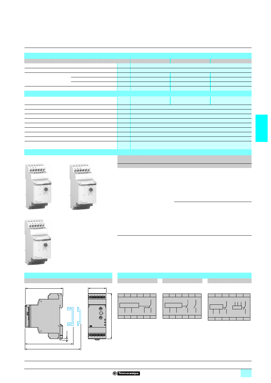
3/85
3
Characteristics
(continued),
references,
dimensions,
schemes
3
Zelio Control
-
modular measurement
and control relays
3
Temperature control relays RM35 AT
1 for
elevator machine rooms and 3-phase supplies
Time delay characteristics
Relay type
RM35 ATL0MW
RM35 ATR5MW
RM35 ATW5MW
Time delay on crossing the threshold
s
0.1…10, 0 + 10 %
Reset time
s
8
Maximum response time
In case of 3-phase fault
ms
–
–
500
In case of temperature fault
s
3.5 + Tt
3.5 + Tt
3.5 + Tt
On disappearance of fault
s
3.5
3.5
0.5
Delay on pick-up
ms
200
200
200
Output characteristics
Output type
1 C/O contact
2 N/O contacts
2 N/O contacts
Contact type
Cadmium-free
Nominal current
A
5
Maximum switching voltage
V
1/2 250
Rated breaking capacity
VA
1250
Minimum breaking current
mA
10/
2 5 V
Electrical durability
1 x 10
5
operating cycles
Mechanical durability
30 x 10
6
operating cycles
Maximum operating rate
360 operations/hour under full load
Utilisation categories
Conforming to IEC 60947-5-1
AC-12, AC-13, AC-14, AC-15, DC-12, DC-13, DC-14
References
Function
Supply
3-phase
control
Output
Reference
Weight
V
V
kg
5 Overtemperature :
34…46 °C
5 Under-temperature
- 1…11 °C
1/2 24…240 –
1 C/O
5 A
RM35 ATL0MW
0.130
–
2 N/O
5 A
RM35 ATR5MW
0.130
5 Overtemperature :
34…46 °C
5 Under-temperature
- 1…11 °C
5 Phase sequence
5 Phase failure
1/2 24…240 1 208…480 2 N/O
5 A
RM35 ATW5MW
0.130
Dimensions
Schemes
RM35 AT
22
22
22
22MW
RM35 ATL0MW
RM35 ATR5MW
RM35 ATW5MW
mm/In.
RM35 ATL0MW
10
568
8
RM35 ATR5MW
10
56
89
RM35 ATW5MW
2,8
0.11
76/
2.99
72,5/
2.85
72/
2.83
90/
3.54
35/
1.38
11
12
14
A1
A2
11
12
14
A1
A2
A
B
R
B
21
24
11
14
A1
A2
A1
A2
A
B
B
14
11
24
21
R1
R2
A1
A2
A1
A2
A
B
L1
L2
L3
B
11
21
24
14
14
24
11
21
L1
L2
L3
R1
R2
Presentation, description :
page 3/82
Operation:
page 3/83
Characteristics:
pages 3/84 and 3/85
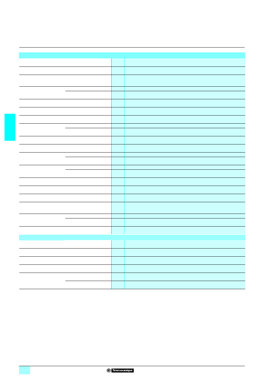
3/86
3
General characteristics
3
Zelio Control - industrial
measurement and control relays
3
RM4 relays
(1) Value not communicated
(2) Except RM4-T, see page 3/91.
Environment
Conforming to standards
IEC 60255-6, EN 60255-6
Product certifications
CSA, GL, UL, pending
14
14
14
14marking
LVD 73/23/EEC and
EMC 89/336/EEC
Zelio Control measurement relays conform to European regulations relating to
6
marking
Ambient air temperature
around the device
Storage
°C
- 40…+ 85
Operation
°C
- 20…+ 65
Permissible relative
humidity range
Conforming to IEC 60721-3-3
15…85 % Environmental class 3K3
Vibration resistance
Conforming to IEC 60068-2-6,
10 to 55 Hz
a = 0.35 ms
Shock resistance
Conforming to IEC 60068-2-27
15 gn - 11 ms
Degree of protection
Conforming to IEC 60529
Casing
IP 50
Terminals
IP 20
Degree of pollution
Conforming to IEC 60664-1
3
Overvoltage category
Conforming to IEC 60664-1
III
Rated insulation voltage
Conforming to IEC
V
500
Conforming to CSA
V
(1)
Test voltage for
insulation tests
Dielectric test
kV
2,5
Shock wave
kV
4,8
Voltage limits
Power supply circuit
0.85…1.1 Uc (2)
Frequency limits
Power supply circuit
50/60 ± 5 %
Disconnection value
Power supply circuit
> 0.1 Uc (2)
Mounting position
without derating
In relation to normal vertical
mounting plane
Any position
Cabling
Maximum c.s.a.
Conforming to IEC 60947-1
Flexible cable without cable end mm
2
2 x 2.5
Flexible cable with cable end
mm
2
2 x 1.5
Tightening torque
Conforming to IEC 60947-1
N.m
0.6…1.1
Immunity to electromagnetic interference (EMC)
(Application class 2 conforming to EN 61812-1)
Electrostatic discharge
Conforming to IEC 61000-4-2
Level 3 (6 kV contact, 8 kV air)
Electromagnetic fields
Conforming to IEC 61000-4-3
Level 3 (10 V/m)
Fast transients
Conforming to IEC 61000-4-4
Level 3 (2 kV)
Shock waves
Conforming to IEC 61000-4-5
Level 3 (2 kV)
Radiated and conducted
emissions
CISPR11
Group 1 class A
CISPR22
Class A
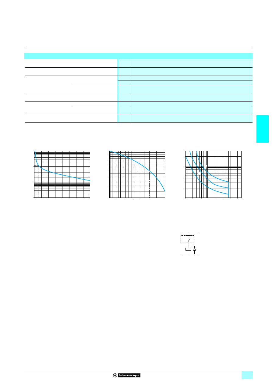
3/87
3
General characteristics
(continued)
3
Zelio Control - industrial
measurement and control relays
3
RM4 relays
Output circuit characteristics
Mechanical durability
In millions of operating cycles
30
Current limit Ith
A
8
Rated operational limits at 70 °C
Conforming to IEC 60947-5-1/1991
and VDE 0660
V
24
115
250
AC-15
A
3
3
3
DC-13
A
2
0.3
0.1
Minimum switching capacity
12 V/10 mA
Switching voltage
Rated
V
1 250
Max.
V
1 440
Contact material
90/10 nickel silver
a.c. load
d.c. load
Curve 1
Curve 2
Load limit curve
Electrical durability of contacts on resistive load
in millions of operating cycles
Reduction factor k for inductive loads (applies to
values taken from durability Curve 1)
Example:
1
L/R = 20 ms
2
L/R with load protection diode
An LC1-F185 contactor supplied with 115 V/50 Hz for a consumption of 55 VA or a current consumption
equal to 0.5 A and cos
ϕ = 0.3.
For 0.5 A, curve 1 indicates a durability of approximately 1.5 million operating cycles.
As the load is inductive, it is necessary to apply a reduction coefficient k to this number of cycles as indicated
by curve 2.
For cos
ϕ = 0.3: k = 0.6
The electrical durability therefore becomes:
1.5 10
6
operating cycles x 0.6 = 900 000 operating cycles.
3
Resistive load
10
1
0,1
0,01
0
1
2
3
4
5
6
7
8
Current broken in A
M
illions
of ope
ra
ting
cycles
1
0,6
0,5
0,9
0,8
0,7
0,4
0,3
1
0,8
0,6 0,5
0,4
0,3
0,2
Power factor on breaking (cos
ϕ)
R
educti
o
n
factor
k
300
40
30
200
100
50
20
10
0,1
0,2
0,5
1
2
5
20
10
1
2
3
Current in A
V
o
lt
ag
e i
n
V
RM4
K
+
–
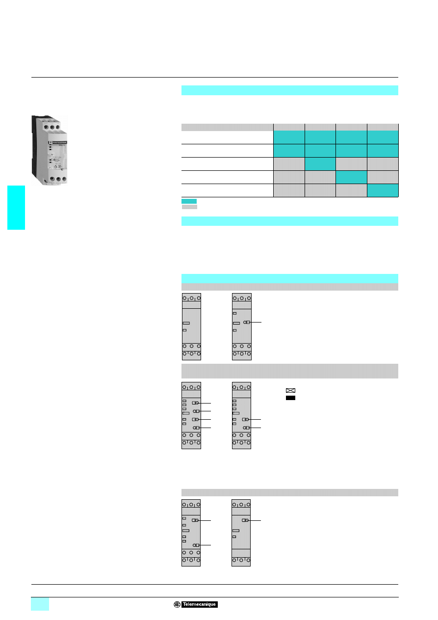
3/88
3
Presentation
3
Zelio Control - industrial
measurement and control relays
3
3-phase supply control relays RM4 T
These devices are designed to monitor 3-phase supplies and to protect motors and
other loads against the faults listed in the table below.
They have a transparent, hinged flap on their front face to avoid any accidental
alteration of the settings. This flap can be directly sealed.
5 Control for connection of moving equipment (site equipment, agricultural equipment,
refrigerated trucks).
5 Control for protection of persons and equipment against the consequences of reverse
running (lifting, handling, elevators, escalators, etc.).
5 Control of sensitive 3-phase supplies.
5 Protection against the risk of a driving load (phase failure).
5 Normal/emergency power supply switching.
Functions
RM4 TG
RM4 TU
RM4 TR
RM4 TA
Monitoring of rotational
direction of phases
Detection of complete failure
of one or more of the phases
Undervoltage detection
Overvoltage and undervoltage
detection (2 thresholds)
Detection of phase asymmetry
(imbalance)
Function performed
Function not performed
RM4 T
56
10
11
Applications
References :
page 3/92
Characteristics :
page 3/91
Dimensions, schemes :
page 3/93
Presentation
RM4 TG
RM4 TU
R
Yellow LED: indicates relay output state.
<U Red LED: undervoltage fault.
1
Undervoltage setting potentiometer.
RM4 TR31,
RM4 TR33,
RM4 TR32
RM4 TR34
1
Time delay function selector:
Fault detection delayed
Fault detection extended
2
Potentiometer for setting time delay in seconds.
3
Potentiometer for setting overvoltage as a direct
value.
4
Potentiometer for setting undervoltage as a direct
value.
R
Yellow LED: indicates relay output state.
U
Green LED: indicates that supply to the RM4 is on.
>U Red LED: overvoltage fault.
<U Red LED: undervoltage fault.
P
Red LED: phase failure or incorrect
rotational direction of phases.
RM4 TA3
RM4 TA0
1
Asymmetry threshold setting potentiometer,
from 5 to 15 %.
2
Potentiometer for setting time delay, 0.1 to 10 s.
R
Yellow LED: indicates relay output state.
U
Green LED: indicates that supply to the RM4 is on.
A
Red LED: phase asymmetry.
P
Red LED: phase failure or incorrect rotational
direction of phases.
R
1
R
<U
3
4
1
2
R
U
<U
P
>U
1
2
R
U
<U
P
>U
1
2
R
U
P
A
1
R
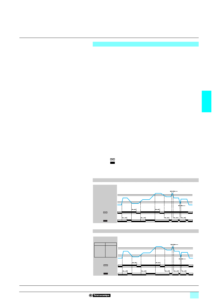
3/89
3
Presentation
(continued)
3
Zelio Control - industrial
measurement and control relays
3
3-phase supply control relays RM4 T
The supply voltage to be monitored is connected to terminals L1, L2, L3 of the
product.
There is no need to provide a separate power supply for RM4 T relays, they are self-
powered by terminals L1, L2, L3.
2222 Monitoring rotational direction of phases and detection of complete failure
of one or more phases (RM4 T all models):
26When terminals L1, L2, L3 are energised, the relay is energised and the yellow
LED comes on if the rotational direction of phases is correct and if all 3 phases are
present.
26If one or more of the phases have failed or if the rotational direction is incorrect,
the relay is not energised at switch-on.
26In normal operation (no fault) the relay is energised; it de-energises
instantaneously in the event of failure of one or more of the phases (any time delay
set is not active on these faults).
26In the event of failure or absence of a single phase, a voltage greater than the
detection threshold (
≈ 130 V on RM4 TG, undervoltage threshold setting on RM4 TU
and RM4 TR) can be generated back through the control circuit, thus preventing
detection of the phase failure. In this case, we recommend the use of RM4 TA relays.
26The absence of a phase is signalled, on RM4 TR and RM4 TA, by illumination of
LED “P”.
2222 Overvoltage and undervoltage detection (RM4 TR):
26In normal operation, the relay is energised and LEDs "U" and "R" are illuminated.
26If the average of the 3 voltages between phases goes outside the range to be
monitored, the output relay is de-energised:
- overvoltage: the red LED “> U” illuminates,
- undervoltage: the red LED “< U” illuminates.
26When the supply returns towards its rated value, the relay is re-energised
according to the hysteresis value (5 %) and the corresponding red LED goes out.
26A selector switch allows selection of an adjustable time delay from 0.1 s to 10 s.
With function
transient "over" or "under" voltages are not taken into account.
With function
all variations above or below are taken into account and
re-energisation of the relay is delayed.
26In all cases, in order to be detected, the duration of the overvoltage or undervoltage
must be greater than the measuring cycle time (80 ms).
Operating principle
Function diagram (RM4 TR31, RM4 TR32)
t
t
< t
t
t
t
t
t
< t
15/18 25/28
15/16 25/26
15/18 25/28
15/16 25/26
RM4 TR31
RM4 TR32
U
L1 L2 L3
0 Volt
Setting > U
0.95 x Setting > U
1.05 x Setting < U
Setting < U
Function
Function
t: time delay
Function diagram (RM4 TR33, RM4 TR34)
t
t
< t
t
t
t
< t
15/18 25/28
15/16 25/26
15/18 25/28
15/16 25/26
242 V 440 V
230 V 418 V
208 V 378 V
198 V 360 V
RM4 TR33
RM4 TR34
TR33 TR34
U
L1 L2 L3
t
t
0 Volt
t: time delay
Function
Function
References :
page 3/92
Characteristics :
page 3/91
Dimensions, schemes :
page 3/93
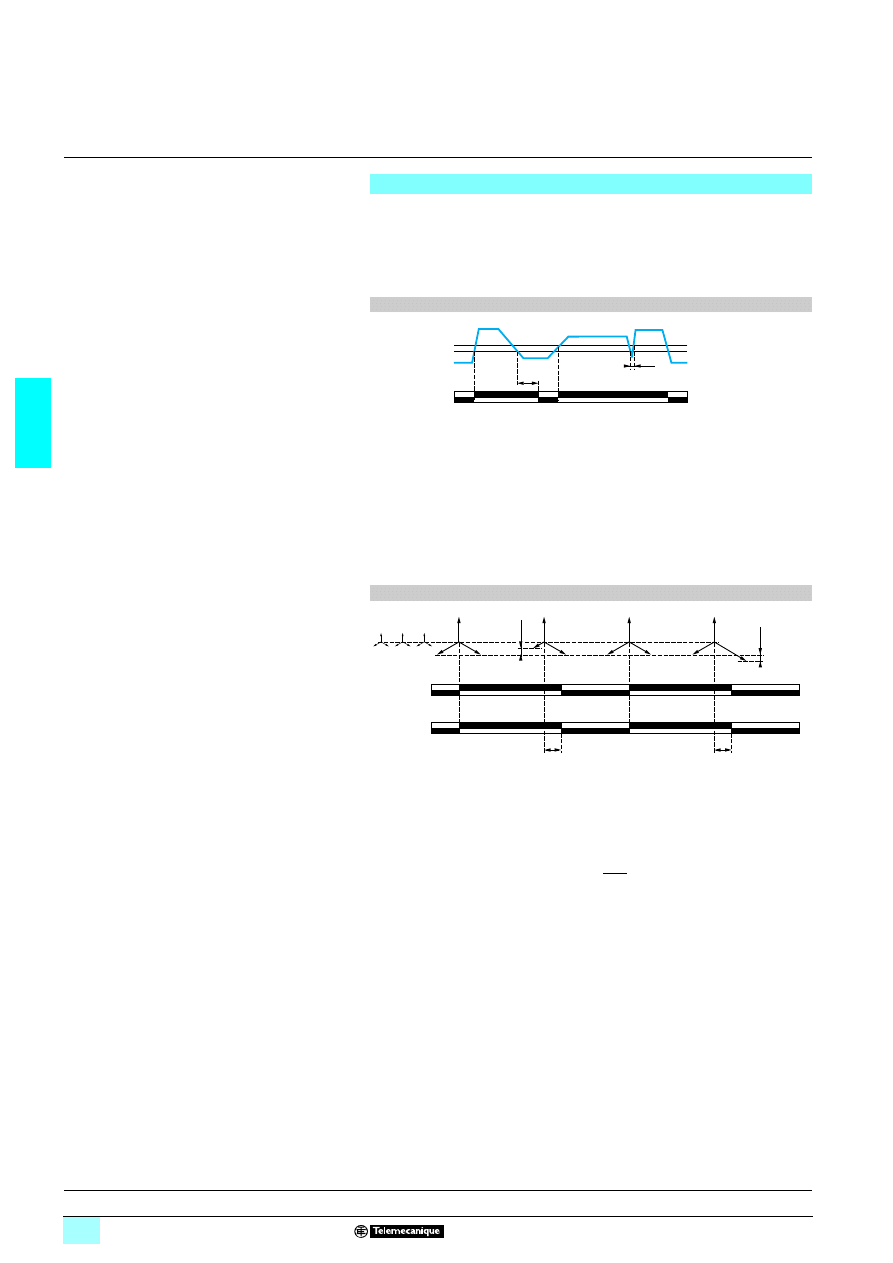
3/90
3
Presentation
(continued)
3
Zelio Control - industrial
measurement and control relays
3
3-phase supply control relays RM4 T
2222 Undervoltage detection only (RM4 TU)
26In normal operation, the output relay is energised and the yellow LED is
illuminated.
26If the average of the 3 voltages between phases is less than the undervoltage
threshold setting, the relay is de-energised after 550 ms and the red LED “< U”
illuminates.
t : fixed time delay = 550 ms
2222 Detection of phase asymmetry (RM4 TA)
26In normal operation, the output relay is energised and the yellow and green LEDs
are illuminated.
26In the event of an asymmetry fault, after a time delay set between 0.1 s and 10 s
(on RM4 TA3 only), the output relay is de-energised, the yellow LED goes out and
red LED “A” illuminates (RM4 TA3
3 only).
26The relay re-energises when the asymmetry value measured is less than half of
the asymmetry value setting (hysteresis).
t : time delay
Example: asymmetry set at 10 %, mains supply voltage 400 V
- relay de-energisation threshold: 400 V – 10 % = 360 V, 10 %,
- relay re-energisation threshold: 400 V – 10% = 380 V.
2
Note : If there is distortion of the 3-phase supply sine wave, malfunctioning of the
RM4 T 3-phase supply control relay is possible.
Operating principle (continued)
Function diagram
t
< t
0 volt
15/18 25/28
15/16 25/26
U
L1 L2 L3
1.05 x Setting < U
Setting < U
Function diagram
15-18
15-16
25-28
25-26
t
t
L1
L3 L2
L2
L1 L3
L3
L2 L1
Relay
Asymmetry >
set threshold
Asymmetry >
set threshold
References :
page 3/92
Characteristics :
page 3/91
Dimensions, schemes :
page 3/93
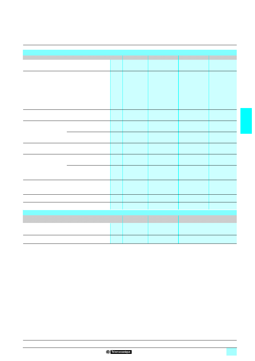
3/91
3
Characteristics
3
Zelio Control - industrial
measurement and control relays
3
3-phase supply control relays RM4 T
Output relay and operating characteristics
Relay type
RM4 TG
RM4 TU
RM4 TR
RM4 TA
Number of C/O contacts
2
2
2
RM4 TA3
7: 2
RM4 TA0
7: 1
Output relay state
Energised during
fault free
operation.
De-energised or
unable to
energise on
detection of
rotational
direction fault or
failure of one or
more phases.
Energised during
fault free operation.
De-energised on
detection of
undervoltage or
rotational direction
fault or failure of one
or more phases.
Energised during
fault free operation.
De-energised on
detection of
overvoltage,
undervoltage or
rotational direction
fault or phase failure.
Energised during
fault free operation.
De-energised on
detection of
asymmetry fault,
phase failure or
rotational direction
fault.
Accuracy of the switching
threshold setting
As % of the set value
–
± 3 %
± 3 %
± 3 %
Switching threshold drift
Depending on the permissible
ambient temperature
–
≤ 0.06 % per degree
centigrade
≤ 0.06 % per degree
centigrade
≤ 0.06 % per
degree centigrade
Within the measuring range
–
≤ 0.5 %
≤ 0.5 %
≤ 0.5 %
Accuracy of the
time delay setting
As % of the full-scale value
–
± 10 %
± 10 %
± 10 %
Time delay drift
Within the measuring range
–
≤ 0.5 %
≤ 0.5 %
≤ 0.5 %
Depending on the rated
operational temperature
–
≤ 0.07 % per degree
centigrade
≤ 0.07 % per degree
centigrade
≤ 0.07 % per
degree centigrade
Hysteresis
Fixed
–
About 5 % of the
de-energisation
threshold
About 5 % of the
de-energisation
threshold
About 50 % of the
asymmetry
percentage
Delay on pick-up
ms
< 650
< 650
< 650
< 650
Measuring cycle
ms
≤ 80
≤ 80
≤ 80
≤ 80
Measuring input characteristics
Relay type
RM4 TG
RM4 T
771
RM4 TR33
RM4 T
772
RM4 TR34
Nominal voltage
V
220…440
RM4 T
771: 220…240
RM4 TR33: 220
RM4 T
772: 380…440
RM4 TR34: 400
Maximum operating range
V
198…484
160…300
290…484
(1) Minimum voltage required for operation of indicators and of the time delay.
Presentation :
pages 3/88 to 3/90
References :
page 3/92
Dimensions, schemes :
page 3/93
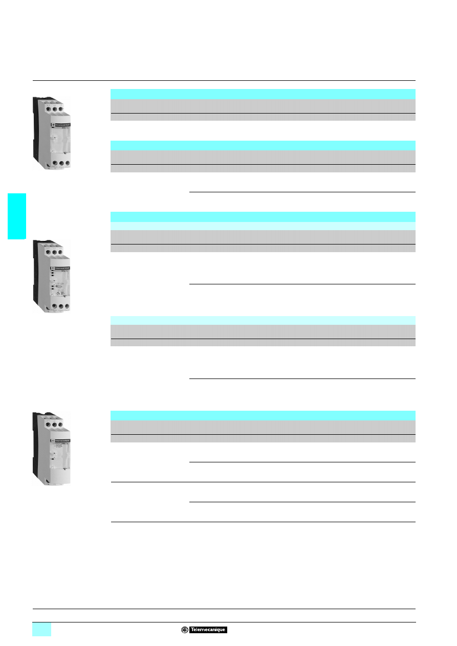
3/92
3
References
3
Zelio Control - industrial
measurement and control relays
3
3-phase supply control relays RM4 T
Control relays: rotational direction and presence of phases
Time delay
Rated mains
supply voltage (1)
Width
Output
relay
Reference
Weight
s
V
mm
kg
Without
220...440
50/60 Hz
22.5
2 C/O
RM4 TG20
0.110
Control relays: rotational direction and presence of phases + undervoltage
Time delay
Rated mains
supply voltage (1)
Control
threshold
Width
Output
relay
Reference
Weight
s
V
V
mm
kg
Without
220…240
50/60 Hz
Undervoltage
160…220
22.5
2 C/O
RM4 TU01
0.110
380…440
50/60 Hz
Undervoltage
300…430
22.5
2 C/O
RM4 TU02
0.110
Control relays: rotational direction and presence of phases + overvoltage & undervoltage
Relays with fixed voltage thresholds
Adjustable time delay
Rated mains
supply voltage (1)
Control
threshold
Width
Output
relay
Reference
Weight
s
V
V
mm
kg
0.1...10
220
50/60 Hz
Undervoltage
198
Overvoltage
242
22.5
2 C/O
RM4 TR33
0.110
400
50/60 Hz
Undervoltage
360
Overvoltage
440
22.5
2 C/O
RM4 TR34
0.110
Relays with adjustable voltage thresholds
Adjustable time delay
Rated mains
supply voltage (1)
Control
threshold
Width
Output
relay
Reference
Weight
s
V
V
mm
kg
0.1…10
220…240
50/60 Hz
Undervoltage
160…220
Overvoltage
220…300
22.5
2 C/O
RM4 TR31
0.110
380…440
50/60 Hz
Undervoltage
300…430
Overvoltage
420…480
22.5
2 C/O
RM4 TR32
0.110
Control relays: rotational direction and presence of phases + asymmetry
Time delay on
de-energisation
Rated mains
supply voltage (1)
Control
threshold
Width
Output
relay
Reference
Weight
s
V
%
mm
kg
Fixed
0.5
220...240
50/60 Hz
Asymmetry
5…15
22.5
1 C/O
RM4 TA01
0.110
380…440
50/60 Hz
Asymmetry
5…15
22.5
1 C/O
RM4 TA02
0.110
Adjustable
0.1…10
220...240
50/60 Hz
Asymmetry
5…15
22.5
2 C/O
RM4 TA31
0.110
380...440
50/60 Hz
Asymmetry
5…15
22.5
2 C/O
RM4 TA32
0.110
(1) Can be used on other supply voltages provided that the minimum operational voltages, maximum voltage between phases and
compatibility with the control threshold ranges are complied with, see page 3/91.
RM4 TG20
56
10
24
RM4 TR33
56
10
25
RM4 TA01
56
10
26
Presentation :
pages 3/88 to 3/90
Characteristics :
page 3/91
Dimensions, schemes :
page 3/93
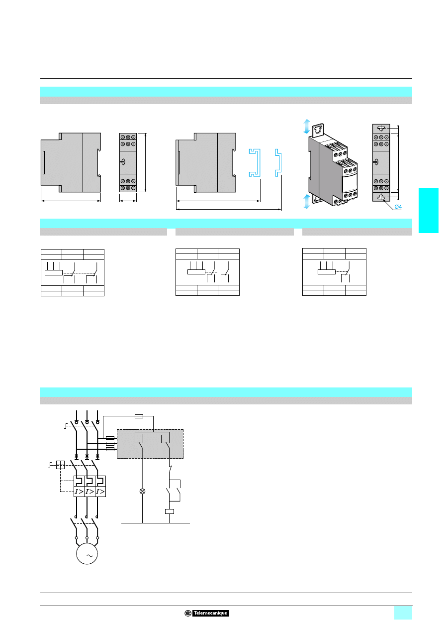
3/93
3
Dimensions,
schemes
3
Zelio Control - industrial
measurement and control relays
3
3-phase supply control relays RM4 T
Dimensions
RM4 T
Rail mounting
Screw fixing
Schemes
RM4 TG20, TU0
2222
RM4 TR3
2222, TA32222
RM4 TA0
2222
L1, L2, L3
Supply to be monitored
L1, L2, L3
Supply to be monitored
L1, L2, L3
Supply to be monitored
15(11)-18(14)
1
st
C/O contact
of the output relay
15-18
1
st
C/O contact
of the output relay
15-18
1
st
C/O contact
of the output relay
15(11)-16(12)
15-16
15-16
25(21)-28(24)
2
nd
C/O contact
of the output relay
25-28
2
nd
C/O contact
of the output relay
25(21)-26(22)
25-26
Application scheme
Example
80
22,5
78
89,5
82
6
6
78
L1
L2
L3
28 (24)
26 (22)
18 (14)
25 (21)
15 (11)
16 (12)
L1
L2
L3
28
25
(21)
26
16
(24)
(22)
18
15
(11)
(14)
(12)
L1
L2
L3
18
15
16
28
25
26
18
15
16
28
25
26
L1
L2
L3
L1
L2
L3
18
15
16
18
15
16
L1
L2
L3
15
18
16
25
28
26
RM4 T
KM1
KM1
1/L1
2
3/L2
4
5/L3
6
Q1
2/T1
4/T2
6/T3
1
Q2
3
5
KM1
1
2
3
4
5
6
U1
W1
V1
M1
3
L3
L2
L1
N
Fault
Start
Stop
Presentation :
pages 3/88 to 3/90
References :
page 3/92
Characteristics :
page 3/91
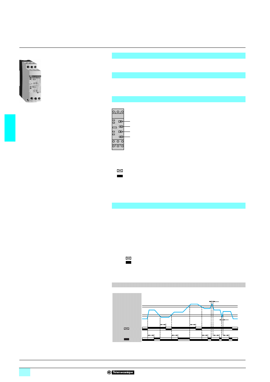
3/94
3
Presentation
3
Zelio Control - industrial
measurement and control relays
3
Voltage control relays RM4 U
1
Overvoltage setting potentiometer.
2
Undervoltage setting potentiometer.
3
Time delay function selector:
4
Potentiometer for setting time delay in seconds.
The voltage to be monitored is connected to terminals L1, L3 of the product.
There is no need to provide a separate power supply for RM4 UB relays, they are
self-powered by terminals L1, L3.
If the voltage goes outside the range to be monitored, the output relay is de-energised:
- overvoltage: the red LED “> U” illuminates,
- undervoltage: the red LED “< U” illuminates.
When the voltage returns towards its rated value, the relay is re-energised according
to the hysteresis value (5 %) and the corresponding red LED goes out.
A selector switch allows selection of an adjustable time delay from 0.1 s to 10 s. With
function
transient "over" or "under" voltages are not taken into account. With
function
all variations above or below are taken into account and re-energisation
of the relay is delayed.
In all cases, in order to be detected, the duration of the overvoltage or undervoltage
must be greater than the measuring cycle time (80 ms).
t : time delay
Functions
These devices are designed for monitoring single-phase voltages.
They have a transparent, hinged flap on their front face to avoid any accidental
alteration of the settings. This flap can be directly sealed.
Applications
1 Protection of electronic or electromechanical devices against overvoltage and
undervoltage.
1 Normal/emergency power supply switching.
Presentation
RM4 UB
RM4 UB
1
2
3
4
R
U
<U
>U
Fault detection delayed.
Fault detection extended.
R
Yellow LED: indicates relay state.
U
Green LED: indicates that supply to the RM4 is on.
> U Red LED: overvoltage fault.
< U Red LED: undervoltage fault.
Operating principle
Function diagram
t
t
< t
t
t
t
t
t
< t
15/18 25/28
15/16 25/26
15/18 25/28
15/16 25/26
RM4 UB34
RM4 UB35
U
L1 L3
0 Volt
Setting > U
0.95 x Setting > U
1.05 x Setting < U
Setting < U
Function
Function
References :
page 3/95
Characteristics :
page 3/96
Dimensions, schemes :
page 3/97
56
10
37
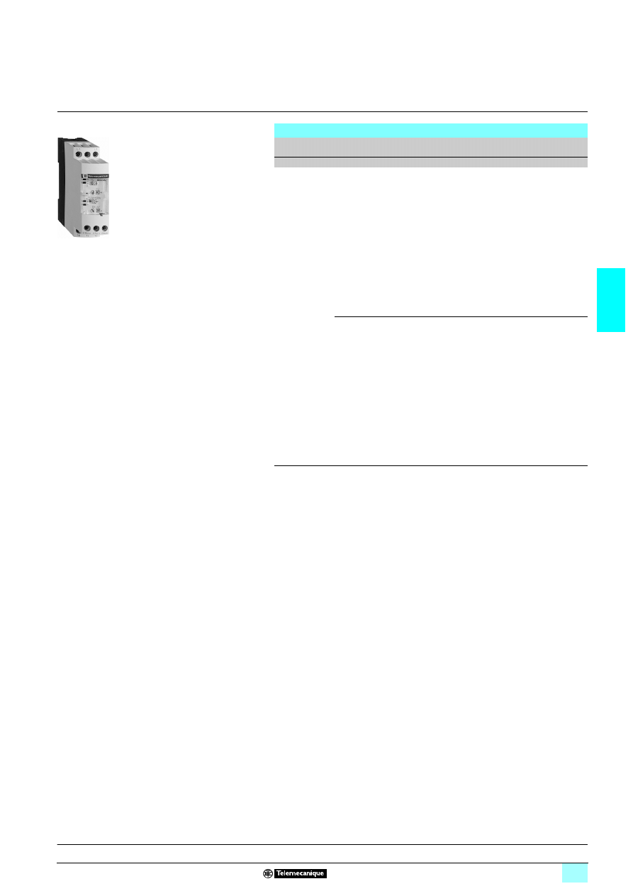
3/95
3
References
3
Zelio Control - industrial
measurement and control relays
3
Voltage control relays RM4 U
Relays with adjustable voltage thresholds
Adjustable
time delay
Control
threshold
Width
Output
relay
Reference
Weight
s
V
mm
kg
0.1…10
Undervoltage
80…120
50/60 Hz
Overvoltage
160…220
22.5
2 C/O
RM4 UB34
0.110
Undervoltage
160…220
50/60 Hz
Overvoltage
220…300
22.5
2 C/O
RM4 UB35
0.110
RM4 UB
Presentation :
page 3/94
Characteristics :
page 3/96
Dimensions, schemes :
page 3/97
56
10
38
3/96
3
Characteristics
3
Zelio Control - industrial
measurement and control relays
3
Voltage control relays RM4 U
Output relay and operating characteristics
Number of C/O contacts
2
Output relay state
Energised during fault free operation.
De-energised on detection of an overvoltage or undervoltage fault
Accuracy of the switching
threshold setting
As % of the set value
± 3 %
Switching threshold drift
Depending on the permissible
ambient temperature
≤ 0.06 % per degree centigrade
Within the measuring range
≤ 0.5 %
Accuracy of the
time delay setting
As % of the full scale value
± 10 %
Time delay drift
Within the measuring range
≤ 0.5 %
Depending on the rated
operational temperature
≤ 0.07 % per degree centigrade
Hysteresis
Fixed
About 5 % of the de-energisation threshold
Measuring cycle
ms
≤ 80
Measuring input characteristics
Minimum operational voltage
V
RM4: 60
RM4 UB35: 160
Maximum permissible voltage
between L1 and L3
V
RM4 UB34: 300
RM4 UB35: 300
Presentation :
page 3/94
References :
page 3/95
Dimensions, schemes :
page 3/97
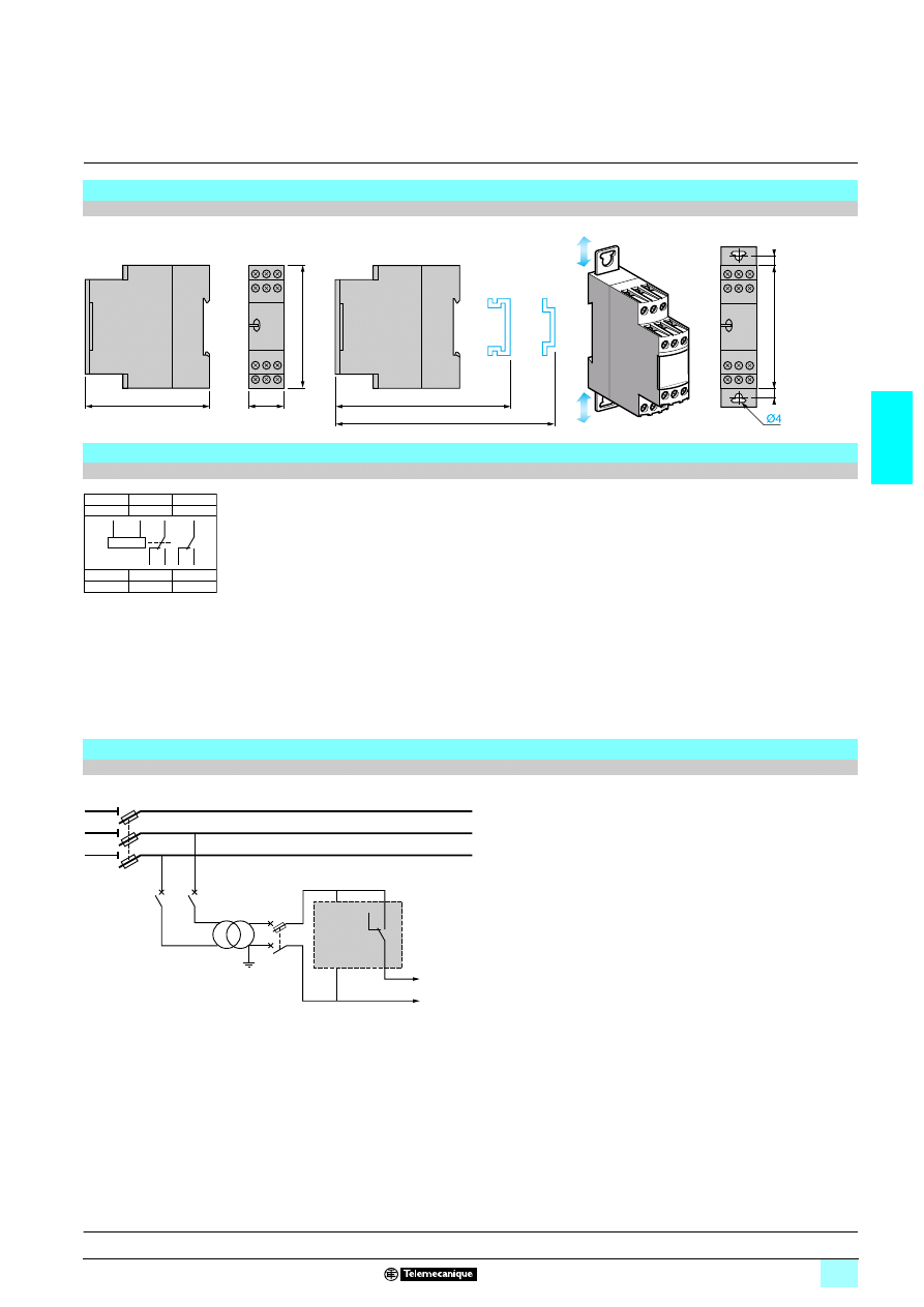
3/97
3
Dimensions,
schemes
3
Zelio Control - industrial
measurement and control relays
3
Voltage control relays RM4 U
Dimensions
RM4 UB
Rail mounting
Screw fixing
Connection schemes
RM4 UB
L1, L3
Voltage to be monitored
15-18
1
st
C/O contact
15-16
of the output relay
25-28
2
nd
C/O contact
25-26
of the output relay
Application scheme
Example
80
22,5
78
89,5
82
6
6
78
L1
L3
18
15
16
28
25
26
18
15
16
28
25
26
L1
L3
15
18
16
Q2
1
2
Q2
1
2
Q1
1/L1
2
3/L2
4
5/L3
6
Q4
RM4 UB
L3
L1
To
sensitive
loads
Presentation :
page 3/94
References :
page 3/95
Characteristics :
page 3/96
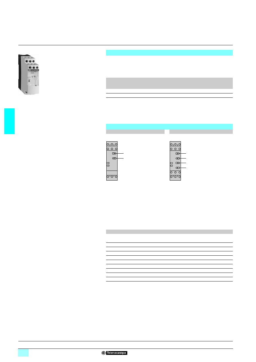
3/98
3
Presentation
3
Zelio Control - industrial
measurement and control relays
3
Voltage measurement relays RM4 U
1
Adjustment of voltage threshold as % of setting range max. value.
2
Hysteresis adjustment from 5 to 30 % (2).
3
Fine adjustment of time delay as % of setting range max. value.
4
Switch combining:
- selection of the timing range: 1s, 3s, 10s, 30s, no time delay,
- selection of overvoltage (>) or undervoltage (<) detection.
See table below.
(1) Selection by switch on front face.
(2) Value of voltage difference between energisation and de-energisation of the output relay
(% of the voltage threshold to be measured).
Functions
These devices are designed to detect when voltage rises above or drops below a
preset threshold, on an a.c. or a d.c. supply.
They have a transparent, hinged flap on their front face to avoid any accidental
alteration of the settings. This flap can be directly sealed.
Relay type
Voltage control
Overvoltage or
undervoltage
detection (1)
Measuring range
RM4 UA0
74
Yes
No
50 mV…500 V
RM4 UA3
7
Yes
Yes
50 mV…500 V
Applications :
- d.c. motor overspeed control,
- battery monitoring,
- monitoring of a.c. or d.c. supplies,
- speed monitoring (with tacho-generator).
Presentation
RM4 UA0
24
24
24
24
RM4 UA3
2222
Width 22.5 mm
Width 22.5 mm
RM4 UA01
1
2
R
U
1
2
3
4
R
U
R
Yellow LED: indicates relay state.
U
Green LED: indicates that supply to the RM4 is on.
Table showing details for switch 4
Switch position
Function
Time delay (t)
< 0
Undervoltage control
No time delay
< 1
Undervoltage control
0.05 to 1 s
< 3
Undervoltage control
0.15 to 3 s
< 10
Undervoltage control
0.5 to 10 s
< 30
Undervoltage control
1.5 to 30 s
> 0
Overvoltage control
No time delay
> 1
Overvoltage control
0.05 to 1 s
> 3
Overvoltage control
0.15 to 3 s
> 10
Overvoltage control
0.5 to 10 s
> 30
Overvoltage control
1.5 to 30 s
References :
page 3/100
Characteristics :
page 3/101
Dimensions, schemes :
page 3/102
Setting-up :
page 3/103
56
10
46
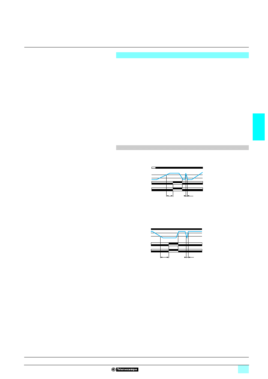
3/99
3
Presentation
(continued)
3
Zelio Control - industrial
measurement and control relays
3
Voltage measurement relays RM4 U
The supply voltage is connected to terminals A1-A2.
The voltage to be monitored is connected to terminals B1, B2 or B3 and C.
Hysteresis is adjustable between 5 and 30%: for overvoltage h = (US1 - US2) / US1,
for undervoltage h = (US2 - US1) / US1.
A measuring cycle lasts only 80 ms, which allows rapid detection of changes in
voltage.
Relay set for overvoltage detection (RM4 UA0
3 or selector on “>” for model
RM4 UA3
3) :
If the voltage is > the setting threshold US1, the output relay is energised with or
without a time delay. When the voltage returns to a value US2 below the threshold,
depending on the hysteresis setting, the relay is instantaneously de-energised.
Relay set for undervoltage detection (selector on “<”, model RM4 UA3
3 only):
If the voltage is < the setting threshold US1, the output relay is energised with or
without a time delay. When the voltage returns to a value US2 above the threshold,
depending on the hysteresis setting, the relay is de-energised.
2222 Functions
2 Overvoltage control
2 Undervoltage control
Note: the measurement ranges can be extended above 500 V by adding a resistor,
see page 3/103.
The measurement range on
4 supply can be extended by means of a voltage
transformer, the secondary of which is connected to the measuring terminals of the
corresponding RM4.
Operating principle
Function diagrams
Voltage
measured
Relay
Function “>”
t : time delay
t
< t
US1
US2
15-18
15-16
25-28
25-26
U supply A1-A2
Relay
Function “<”
t
< t
US1
US2
15-18
15-16
25-28
25-26
Voltage
measured
U supply A1-A2
t : time delay
References :
page 3/100
Characteristics :
page 3/101
Dimensions, schemes :
page 3/102
Setting-up :
page 3/103
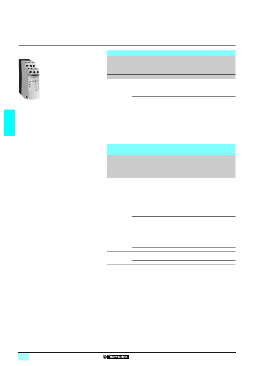
3/100
3
References
3
Zelio Control - industrial
measurement and control relays
3
Voltage measurement relays RM4 U
Voltage measurement relays: overvoltage detection
Time delay
Voltage to be
measured
depending on
connection
5
5
5
5 or 64
64
64
64
Width
Output
relay
Basic reference,
to be completed by
adding the voltage
code (1)
Weight
V
mm
kg
Without
0.05...0.5
22.5
1 C/O
RM4 UA01
2222
0.168
0.3…3
0.5…5
1...10
22.5
1 C/O
RM4 UA02
2222
0.168
5…50
10…100
30...300
22.5
1 C/O
RM4 UA03
2222
0.168
50…500
Voltage measurement relays: overvoltage or undervoltage
detection
Adjustable
time delay
Voltage to be
measured
depending on
connection
5
5
5
5 or 6
6
6
6
Width
Output
relay
Basic reference,
to be completed by
adding the voltage
code (1)
Weight
s
V
mm
kg
0.05...30
0.05...0.5
22.5
2 C/O
RM4 UA31
22
22
22
22
0.168
0.3…3
0.5…5
1...10
22.5
2 C/O
RM4 UA32
22
22
22
22
0.168
5…50
10…100
30...300
22.5
2 C/O
RM4 UA33
22
22
22
22
0.168
50…500
(1) Standard supply voltages
RM4 UA0
1111
1111
Volts
24
110...130 220...240
1 50/60 Hz
B
F
M
RM4 UA3
1111
Volts
24...240
110...130 220...240 380...415
1 50/60 Hz
MW
F
M
Q
2
MW
–
–
–
RM4 UA01
Presentation :
pages 3/98 and 3/99
Characteristics :
page 3/101
Dimensions, schemes :
page 3/102
Setting-up :
page 3/103
5
6
10
46
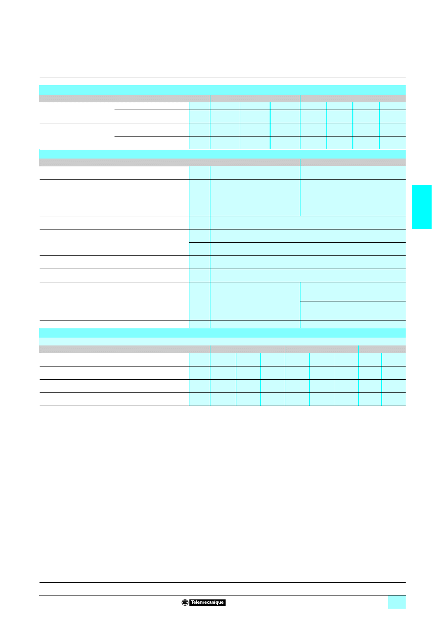
3/101
3
Characteristics
3
Zelio Control - industrial
measurement and control relays
3
Voltage measurement relays RM4 U
Power supply circuit characteristics
Relay type
RM4 UA0
74
RM4 UA3
7
Rated supply voltage (Un)
1 50/60 Hz
V
24
110...130
220...240
24...240
110…130 220...240
380...415
2
V
–
–
–
24...240
–
–
–
Average consumption at Un
1
VA
2
1.9…3.3
2.7…3.5
1.5…3.3
1.9…3.3
2.7…3.4
2.7…3
2
W
–
–
–
1.2
–
–
–
Output relay and operating characteristics
Relay type
RM4 UA0
74
RM4 UA3
7
Number of C/O contacts
1
2
Output relay state
Energised when:
voltage measured > threshold setting
Energised when:
voltage measured > threshold setting
(“>” function)
voltage measured < threshold setting
(“<” function)
Setting accuracy of the switching threshold
As % of the full-scale value: ± 5 %
Switching threshold drift
%
≤ 0.06 per degree centigrade, depending on the permissible ambient temperature
%
≤ 0.5, within the supply voltage range (0.85…1.1 Un)
Hysteresis (adjustable)
%
5…30 of the voltage threshold setting
Setting accuracy of the time delay
As % of the full-scale value: ± 10 %
Time delay drift
%
–
≤ 0.5, within the supply voltage range
(0.85…1.1 Un)
≤ 0.07 per degree centigrade, depending on
rated operating temperature
Measuring cycle
ms
≤ 80
Measuring input characteristics
Internal input resistance and permissible overload depending on the voltage measurement ranges
Relay type
RM4 UA
71
RM4 UA
72
RM4 UA
22223
Measurement range
1 50-60 Hz and 2
V
0.05…0.5 0.3…3
0.5…5
1…10
5…50
10…100
30…300 50…500
Internal input resistance Ri
k
Ω
6.6
43
71
23
112
225
668
1111
Permissible continuous overload
V
20
60
80
90
150
300
400
550
Permissible non repetitive overload
for t
≤ 1 s
V
25
80
100
100
200
400
500
550
Presentation :
pages 3/98 and 3/99
References :
page 3/100
Dimensions, schemes :
page 3/102
Setting-up :
page 3/103
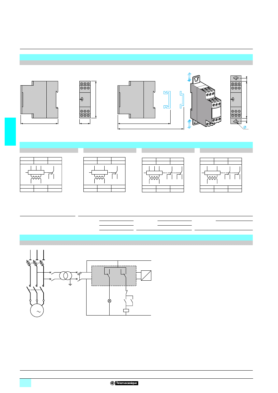
3/102
3
Dimensions,
schemes
3
Zelio Control - industrial
measurement and control relays
3
Voltage measurement relays RM4 U
Dimensions
RM4 UA
4
Rail mounting
Screw fixing
4
Schemes
RM4 UA01, UA02
RM4 UA03
RM4 UA31, UA32
RM4 UA33
A1-A2
Supply voltage
Connection and current values to be measured, depending on type of RM4 UA
B1, B2,
Voltages to be measured
RM4 UA
71
B1-C
0.05…0.5 V
RM4 UA
72 B1-C
1…10 V
RM4 UA
73 B2-C
30…300 V
B3, C
(see table opposite)
B2-C
0.3…3 V
B2-C
5…50 V
B3-C
50…500 V
B3-C
0.5…5 V
B3-C
10…100 V
Application scheme
Example: overspeed monitoring (undervoltage function)
80
22,5
78
89,5
82
4
6
6
78
A1
A2
C
B1
B3
B2
18
16
15
18
15
16
B3
B2
B1
A2
A1
C
A1
A2
C
B3
B2
18
16
15
18
15
16
B3
B2
A2
A1
C
A1
A2
C
B1
B3
B2
26
28
25
18
16
15
18
15
16
B3
28
25
26
B2
B1
A2
A1
C
A1
A2
C
B3
B2
26
28
25
18
16
15
18
15
16
B3
28
25
26
B2
A2
A1
C
Q1
1/L1
2
3/L2
4
5/L3
6
Q4
1
2
Q3
2
1
Q2
2
1
15
18
16
25
28
26
RM4 UA
KM1
KM1
A1
A2
B1
C
U
v
KM1
1
2
3
4
5
6
U1
W1
V1
M1
3
Tacho-generator
Overspeed
Stop
Start
Presentation :
pages 3/98 and 3/99
References :
page 3/100
Characteristics :
page 3/101
Setting-up :
page 3/103
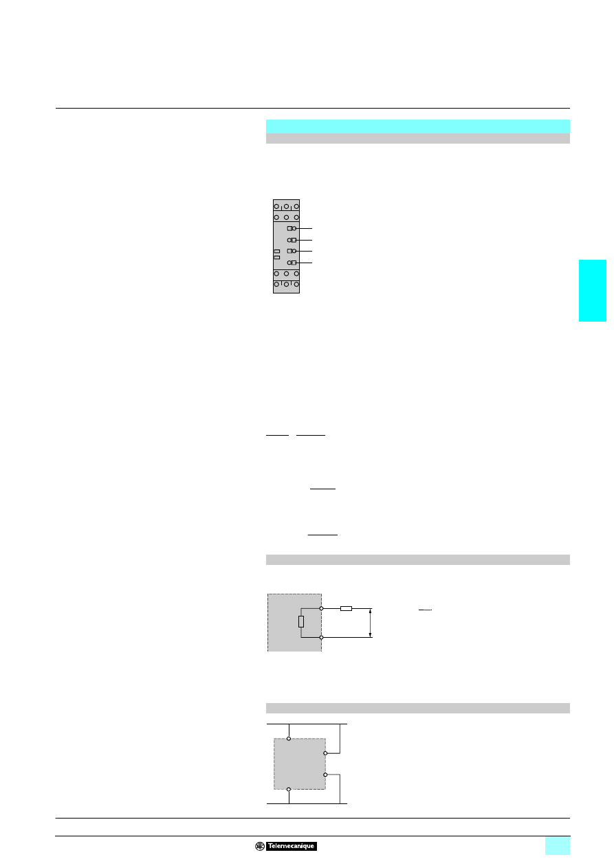
3/103
3
Setting-up
3
Zelio Control - industrial
measurement and control relays
3
Voltage measurement relays RM4 U
Undervoltage threshold to be measured: 12 V
7.
Output relay time delay: 20 s.
Reset voltage threshold: 13.2 V
Supply voltage: 230 V at
1
60 Hz.
1 Adjustments:
2 Adjustment of function and timing range, switch
4
:
- determine the timing range, immediately greater than the time required; in the
above example 30 s,
- determine whether overvoltage or undervoltage detection is required; in this
example, undervoltage,
- position switch
4
according to the above 2 criteria; in this example, switch
4
on
< 30.
2 Fine adjustment of time delay:
Depending on the max. range setting displayed at
4
(in the above example: 30 s)
use potentiometer
3
to set the required time delay as a % of value
4
.
In the above example, the required time = 20 s therefore :
2 Set the voltage threshold setting potentiometer
1
as a percentage of the maximum
value of the measuring range selected when wiring.
In the above example: wiring B2-C, max. value of measuring range = 50 V, therefore:
2 Set the hysteresis
2
as a % of the threshold value; in this example:
Setting-up
Example of undervoltage to be measured
Product selected
RM4 UA32M
Connection of voltage to be measured B2-C (5 to 50 V)
Set the time delay potentiometer
3
to
66
.
Setting
1
=
= 24 %
Set the voltage threshold setting potentiometer
1
to
24
.
Setting
2
=
= 10 %
Set the hysteresis
2
to
10
.
1
2
3
4
R
U
t x 100
4
20 x 100
30
= 66 %
=
12 x 100
50
13.2 - 12
12
Extension of the measuring range
6
6
6
6 or 5
5
5
5
supply
Simply connect an additional resistor (Rs) in series
with the measuring input B3 or C.
If the value of Rs is in the region of:
Rs = Ri
where:
Ri
Internal resistance of input B3-C.
Um Maximum value of threshold setting range.
U
Voltage threshold to be measured.
The tripping threshold of the relay will be towards the maximum graduation on the
threshold setting potentiometer.
In general, the power consumed by the resistor does not exceed 0.5 W.
For a.c. voltages, it is also possible to use a voltage transformer.
Supply by the measured voltage
For monitoring mains and power supplies, the
RM4 UA can be supplied by the voltage to be
controlled, provided that:
- the measurement threshold is within the operating
range of the product's power supply (0.85…1.1 Uc),
- variations of the voltage to be measured are
compatible with the supply and measurement
voltage ranges.
Rs
C
B3
Ri
U > 500 V
RM4 UA33
U
Um
-1
A1
A2
B2/B3
C
RM4 UA
Presentation :
pages 3/98 and 3/99
References :
page 3/100
Characteristics :
page 3/101
Dimensions, schemes :
page 3/102
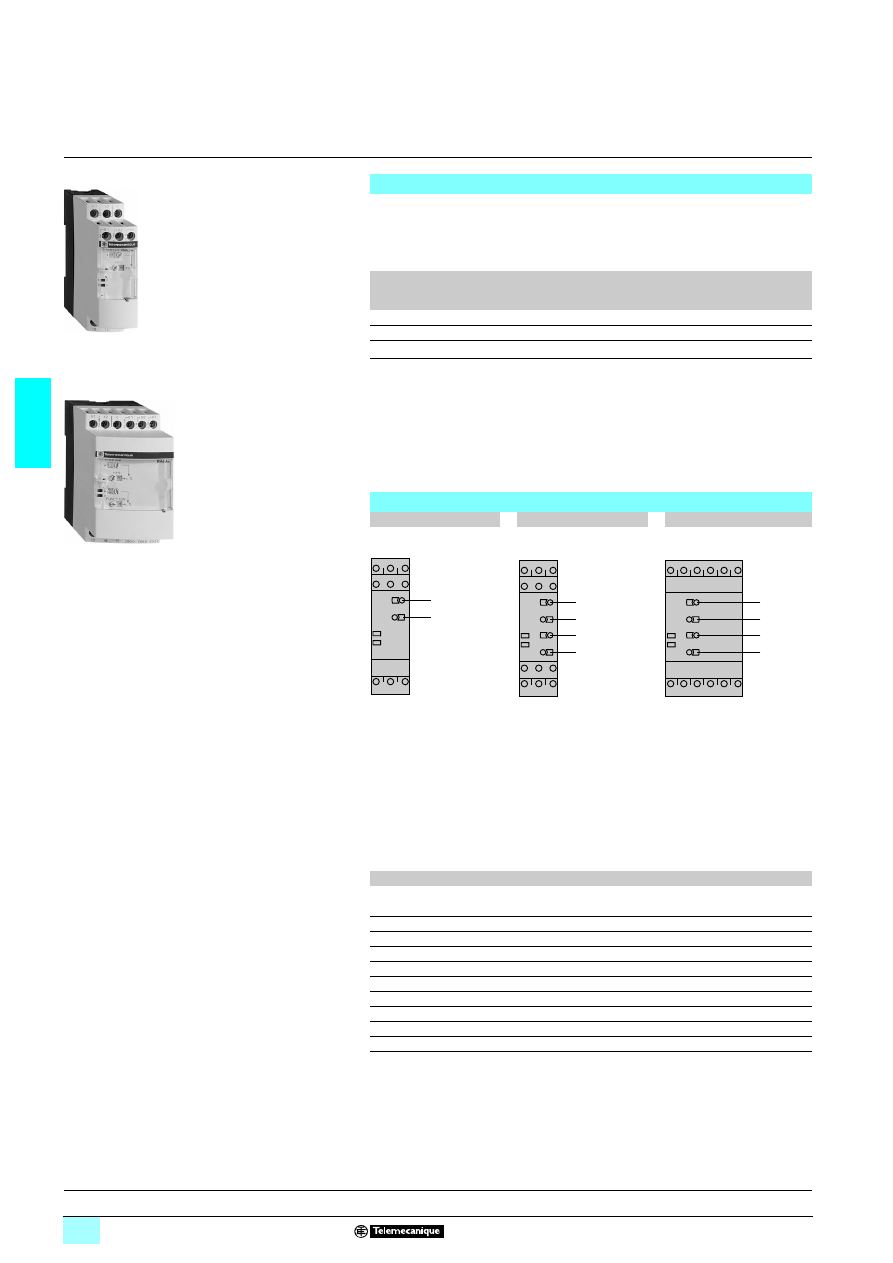
3/104
3
Presentation
3
Zelio Control - industrial
measurement and control relays
3
Current measurement relays RM4 J
1
Adjustment of current threshold as % of setting range max. value.
2
Hysteresis adjustment from 5 to 30 % (2).
3
Fine adjustment of time delay as % of setting range max. value.
4
10-position switch combining:
- selection of the timing range: 1 s, 3 s, 10 s, 30 s, no time delay,
- selection of overcurrent (>) or undercurrent (<) detection.
See table below.
(1) Selection by switch on front face.
(2) Value of current difference between energisation and de-energisation of the output relay
(% of the current threshold to be measured).
Functions
These devices are designed to detect when current rises above or drops below a
preset threshold, on an a.c. or a d.c. supply.
They have a transparent, hinged flap on their front face to avoid any accidental
alteration of the settings. This flap can be directly sealed.
Relay type
Overcurrent
detection
Overcurrent or
undercurrent
detection (1)
Measuring range
RM4 JA01
Yes
No
3 mA…1 A
RM4 JA31
Yes
Yes
3 mA…1 A
RM4 JA32
Yes
Yes
0.3 A…15 A
Applications :
- excitation control of d.c. machines,
- control of load state of motors and generators,
- control of current drawn by a 3-phase motor,
- monitoring of heating or lighting circuits,
- control of pump draining (undercurrent),
- control of overtorque (crushers),
- monitoring of electromagnetic brakes or clutches.
Description
RM4 JA01
RM4 JA31
RM4 JA32
Width 22.5 mm
Width 22.5 mm
Width 45 mm
RM4 JA01
RM4 JA32
1
2
R
U
1
2
3
4
R
U
1
2
3
4
R
U
R
Yellow LED: indicates relay state.
U
Green LED: indicates that supply to the RM4 is on.
Table showing details for switch 4
Switch position
Function
Time delay (t)
< 0
Undercurrent detection
No time delay
< 1
Undercurrent detection
0.05 to 1 s
< 3
Undercurrent detection
0.15 to 3 s
< 10
Undercurrent detection
0.5 to 10 s
< 30
Undercurrent detection
1.5 to 30 s
> 0
Overcurrent detection
No time delay
> 1
Overcurrent detection
0.05 to 1 s
> 3
Overcurrent detection
0.15 to 3 s
> 10
Overcurrent detection
0.5 to 10 s
> 30
Overcurrent detection
1.5 to 30 s
References :
page 3/106
Characteristics :
page 3/107
Dimensions, schemes :
page 3/108
Setting-up :
page 3/109
56
10
61
56
10
62
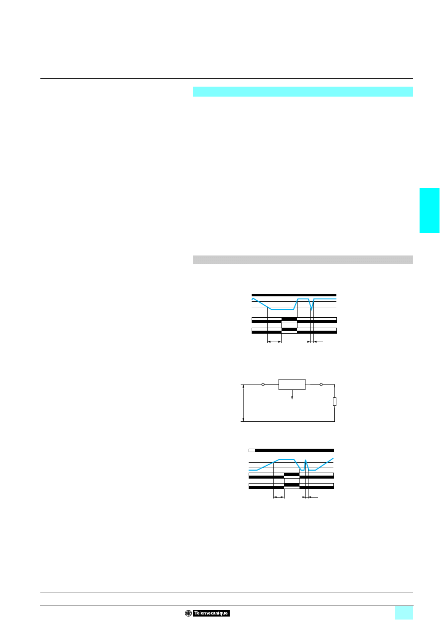
3/105
3
Presentation
(continued)
3
Zelio Control - industrial
measurement and control relays
3
Current measurement relays RM4 J
The supply voltage is connected to terminals A1-A2.
The current to be monitored is connected to terminals B1, B2, B3 and C. See diagram
below.
Hysteresis is adjustable between 5 and 30 %: for overcurrent h = (IS1 - IS2) / IS1,
for undercurrent h = (IS2 - IS1) / IS1.
A measuring cycle lasts only 80 ms, which allows rapid detection of changes in
current.
Relay set for overcurrent detection (RM4 JA01 or selector on “>” for model
RM4 JA3
3).
If the current is > the setting threshold IS1, the output relay is energised with or
without a time delay, depending on the model. When the current returns to a value
IS2 below the threshold, depending on the hysteresis setting, the relay is
instantaneously de-energised.
Relay set for undercurrent detection (selector on “<”, model RM4 JA3
3 only).
If the current is <, the setting threshold IS1, the output relay is energised with or
without a time delay, depending on the model. When the current returns to a value
IS2 above the threshold, depending on the hysteresis setting, the relay is
instantaneously de-energised.
1 Functions
2 Undercurrent detection
2 Overcurrent detection
Note: The measurement ranges can be extended by means of a current transformer,
the secondary of which is connected to the measuring terminals of the RM4 relay, or
by means of a resistor connected in parallel with the measuring input (see example
page 3/109 “Setting-up”).
Operating principle
Function diagrams
t
< t
IS1
IS2
15-18
15-16
25-28
25-26
A1-A2
Current measured
Relay
U supply
Function “<”
t : time delay
B1, B2, B3
RM4 JA
C
Load
U drop < 1 V
Mea
s
urem
ent
t
< t
IS1
IS2
15-18
15-16
25-28
25-26
A1-A2
Current
measured
Relay
U supply
Function “>”
t : time delay
References :
page 3/106
Characteristics :
page 3/107
Dimensions, schemes :
page 3/108
Setting-up :
page 3/109
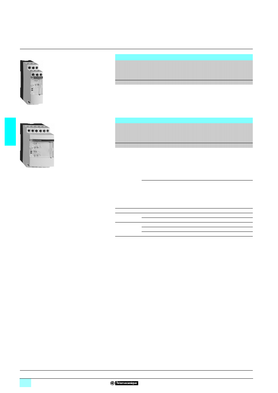
3/106
3
References
3
Zelio Control - industrial
measurement and control relays
3
Current measurement relays RM4 J
Overcurrent detection
Time delay
Current to
be measured
depending on
connection
5
5
5
5 or 64
64
64
64
Width
Output
relay
Basic reference,
to be completed by
adding the voltage
code (1)
Weight
s
mm
kg
Without
3...30 mA
22.5
1 C/O
RM4 JA01
2222
0.172
10...100 mA
0.1...1 A
Overcurrent or undercurrent detection
Adjustable
time delay
Current to
be measured
depending on
connection
5
5
5
5 or 64
64
64
64
Width
Output
relay
Basic reference,
to be completed by
adding the voltage
code (1)
Weight
s
mm
kg
0.05...30
3...30 mA
22.5
2 C/O
RM4 JA31
22
22
22
22
0.172
10...100 mA
0.1...1 A
0.3...1.5 A
45
2 C/O
RM4 JA32
224
224
224
224
0.204
1...5 A
3...15 A
(1) Standard supply voltages
RM4 JA01
Volts
24
110...130 220...240
1 50/60 Hz
B
F
M
RM4 JA31
Volts
24...240
110...130 220...240 380...415
and RM4 JA32
1 50/60 Hz
MW
F
M
Q
2
MW
–
–
–
RM4 JA01
RM4 JA32
Presentation :
pages 3/104 and 3/105
Characteristics :
page 3/107
Dimensions, schemes :
page 3/108
Setting-up :
page 3/109
56
10
68
56
10
69
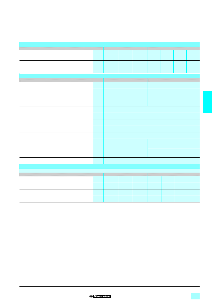
3/107
3
Characteristics
3
Zelio Control - industrial
measurement and control relays
3
Current measurement relays RM4 J
Power supply circuit characteristics
Relay type
RM4 JA01
RM4 JA31 and RM4 JA32
Rated supply voltage (Un)
1 50/60 Hz
V
24
110...130
220...240
24...240
110…130 220...240
380...415
2
V
–
–
–
24...240
–
–
–
Average consumption at Un
1
VA
2
1.9…3.3
2.7…3.5
1.5…3.3
1.9…3.3
2.7…3.4
2.7…3
2
W
–
–
–
1.2
–
–
–
Output relay and operating characteristics
Relay type
RM4 JA01
RM4 JA31 and RM4 JA32
Number of C/O contacts
1
2
Output relay state
Energised when:
current measured > threshold setting
Energised when:
current measured > threshold setting
(“>” function)
current measured < threshold setting
(“<” function)
Setting accuracy of the switching threshold
As % of the full-scale value: ± 5 %
Switching threshold drift
%
≤ 0.06 per degree centigrade, depending on the permissible ambient temperature
%
≤ 0.5, within the supply voltage range (0.85…1.1 Un)
Hysteresis (adjustable)
%
5…30 of the current threshold setting
Setting accuracy of the time delay
As % of the full-scale value: ± 10 %
Time delay drift
%
–
≤ 0.07 per degree centigrade, depending on
temperature
≤ 0.5, within the supply voltage range
(0.85… 1.1 Un)
Measuring cycle
ms
≤ 80
Measuring input characteristics
Internal input resistance and permissible overload depending on the current measurement ranges
Relay type
RM4 JA01 and RM4 JA31
RM4 JA32
Measurement range
1450-60 Hz and 6
6
6
6
3…30 mA
10…100 mA 0.1…1 A
0.3…1.5 A 1… 5 A
3… 15 A
Internal input resistance Ri
Ω
33
10
1
0.06
0.02
0.006
Permissible continuous overload
A
0.05
0.15
1.5
2
7
20
Permissible non repetitive overload
for t
≤ 3 s
A
0.2
0.5
5
10
15
100
Presentation :
pages 3/104 and 3/105
References :
page 3/106
Dimensions, schemes :
page 3/108
Setting-up :
page 3/109
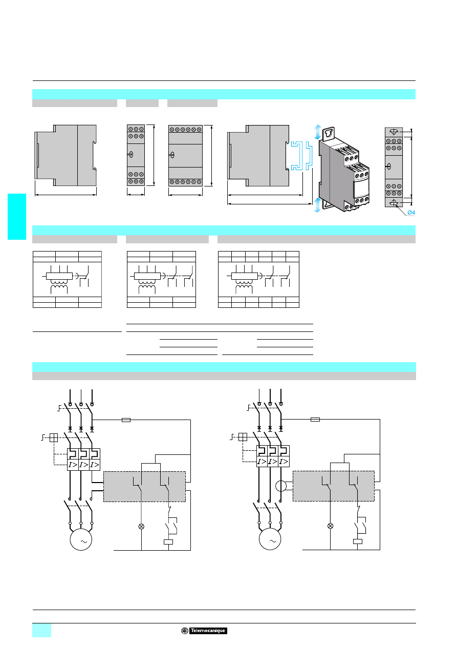
3/108
3
Dimensions,
schemes
3
Zelio Control - industrial
measurement and control relays
3
Current measurement relays RM4 J
Dimensions
RM4 JA (common side view)
RM4 JA
2222
RM4 JA32
Rail mounting
Screw fixing
4
Connection schemes
RM4 JA01
RM4 JA31
RM4 JA32
A1-A2
Supply voltage
Connection and current values to be measured, depending on type of RM4 JA
B1, B2,
Currents to be measured
RM4 JA01
B1-C
3…30 mA
RM4 JA32
B1-C
0.3…1.5 A
B3, C
(see table opposite)
& RM4 JA31 B2-C
10…100 mA
B2-C
1…5 A
B3-C
0.1…1 A
B3-C
3…15 A
Application schemes
Example: detection of blockage on a crusher (overcurrent function)
Current measured
≤ 15 A
Current measured > 15 A
80
22,5
78
45
78
89,5
82
6
6
78
A1
A2
C
B1
B3
B2
18
16
15
18
15
16
B3
B2
B1
A2
A1
C
A1
A2
C
B1
B3
B2
26
28
25
18
16
15
18
15
16
B3
28
25
26
B2
B1
A2
A1
C
A1
A2
C
B1
B2
B3
18
16
15
28
26
25
18
15
16
B3
28
25
26
B2
B1
A2
A1
C
15
18
16
25
28
26
RM4 JA3
KM1
KM1
1/L1
2
3/L2
4
5/L3
6
Q1
2/T1
4/T2
6/T3
1
Q2
3
5
KM1
1
2
3
4
5
6
U1
W1
V1
M1
3
B3
C
A1
A2
N
Overtorque
Start
Stop
15
18
16
25
28
26
RM4 JA3
KM1
KM1
1/L1
2
3/L2
4
5/L3
6
Q1
2/T1
4/T2
6/T3
1
Q2
3
5
KM1
1
2
3
4
5
6
U1
W1
V1
M1
3
B3
C
A1
A2
N
Overtorque
Start
Stop
Presentation :
pages 3/104 and 3/105
References :
page 3/106
Characteristics :
page 3/107
Setting-up :
page 3/109
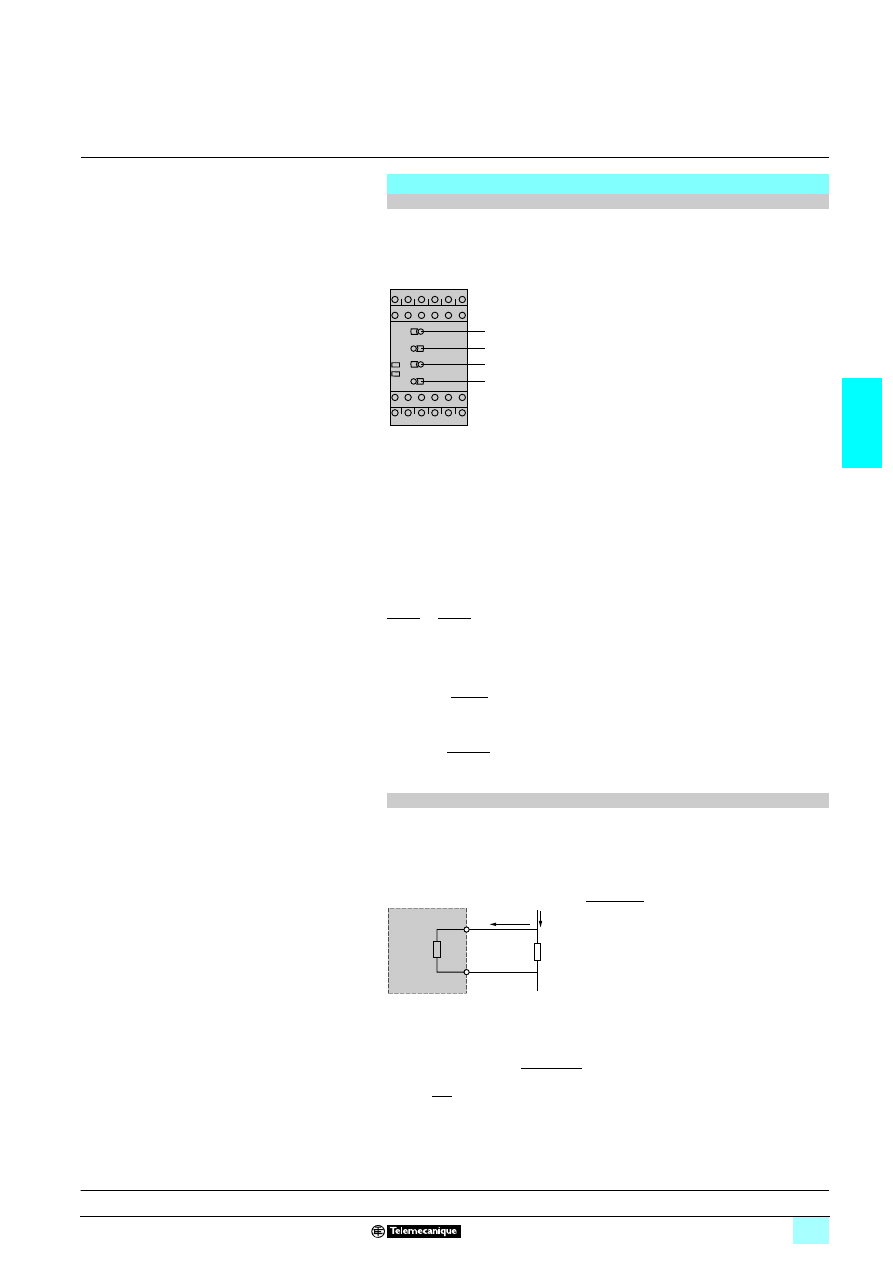
3/109
3
Setting-up
3
Zelio Control - industrial
measurement and control relays
3
Current measurement relays RM4 J
Overcurrent threshold at: 13 A.
Output relay time delay: 5 s.
Reset current threshold: 11 A
Supply voltage: 127 V
7666
1 Adjustments:
2 Adjustment of function and timing range, switch
4
:
- determine whether overcurrent or undercurrent detection is required; in this
example, overcurrent,
- determine the timing range, immediately greater than the time required; in this
example 10 s,
- position switch
4
according to the above 2 criteria; in this example, switch
4
on > 10.
2 Fine adjustment of time delay:
Depending on the max. range setting displayed at
4
(in the above example: 10 s) use
potentiometer
3
to set the required time delay as a % of value
4
.
In the above example, the required time = 5 s therefore:
2 Set the current threshold setting potentiometer
1
as a percentage of the maximum
value of the measuring range selected when wiring.
In the above example: wiring B3-C, max. value of measuring range = 15 A, therefore:
2 Set the hysteresis
2
as a % of the threshold value; in this example:
1 d.c. or a.c. supply
Simply connect a resistor “Rs” to terminals B1-C (or B2, B3-C) on the measuring
input.
The relay energisation threshold will be towards the middle of the setting
potentiometer range if the value of Rs is in the region of:
1 Application:
Use of relay RM4 JA31
33 (10 to 100 mA).
Connection B2-C to measure a threshold of 1 A, knowing that Ri = 10
Ω
for this rating
and that Im = 100 mA.
The value of Rs will be:
= 0.526
Ω
P = (1 -
)
2
x 0.526 i.e. 0.47 W
Select a resistor Rs capable of dissipating at least twice the calculated value, i.e.
1 W for this example, in order to limit temperature rise.
On an a.c. supply, it is also possible to use a current transformer.
Setting-UP
Example of overcurrent to be measured
Product selected RM4 JA32MW
Connection of current to be measured B3-C (3 to 15 A)
Set the time delay potentiometer
3
to
50
.
Setting
1
=
= 87 %
Set the current threshold setting potentiometer
1
to
87
.
Setting
2
=
= 15.4 %
Set the hysteresis
2
to
15
(13 - 11 = 2 i.e. 15.4 % of the current to be measured).
1
2
3
4
R
U
t x 100
4
5 x 100
10
= 50 %
=
13 x 100
15
13 - 11
13
Extension of the measuring range
Rs
=
where:
Ri
Internal resistance of input B1-C,
Im
Maximum value of threshold setting range,
I
Current threshold to be measured.
Power dissipated by Rs: P = Rs (I -Im/2)
2
Rs
B1
C
RM4 JA
Ri
Ii = Im/2
I
Ri
(2I/Im) - 1
10
(2 x 1/0.1) - 1
0.1
2
Presentation :
pages 3/104 and 3/105
References :
page 3/106
Characteristics :
page 3/107
Dimensions, schemes :
page 3/108
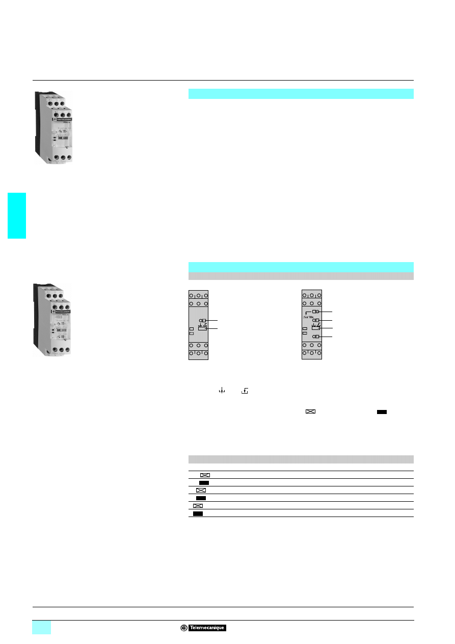
3/110
3
Presentation
3
Zelio Control - industrial
measurement and control relays
3
Liquid level control relays RM4 L
Functions
These devices monitor the levels of conductive liquids.
They control the actuation of pumps or valves to regulate levels and are also suitable
for protecting submersible pumps against running empty, or protecting tanks from
"overflow". They can also be used to control dosing of liquids in mixing processes
and to protect heating elements in the event of non immersion.
They have a transparent, hinged flap on their front face to avoid any accidental
alteration of the settings. This flap can be directly sealed.
1 Compatible liquids:
2 spring, town, industrial and sea water,
2 metallic salt, acid or base solutions,
2 liquid fertilizers,
2 non concentrated alcohol (< 40 %),
2 liquids in the food-processing industry: milk, beer, coffee, etc.
1 Non-compatible liquids:
2 chemically pure water,
2 fuels, liquid gasses (inflammable),
2 oil, concentrated alcohol (> 40 %),
2 ethylene, glycol, paraffin, varnish and paints.
Description
RM4 LG01
RM4 LA32
Width 22.5 mm
Width 22.5 mm
1
Fine adjustment of time delay (as % of setting range max. value).
2
Fine adjustment of response sensitivity (as % of setting range max. value).
3
Function selector switch:
- empty
or fill
.
4
Switch combining:
- selection of the response sensitivity range,
- selection of time delay on energisation
or on de-energisation
of the
relay.
RM4 LG01
RM4 LA32
2
3
R
U
1
2
4
R
U
3
R
Yellow LED: indicates relay state.
U
Green LED: indicates that supply to the RM4 is on.
Table showing details for switch 4
Switch position
Time delay
Sensitivity
500
On-delay
High = 500 k
Ω range
500
Off-delay
High = 500 k
Ω range
50
On-delay
Medium = 50 k
Ω range
50
Off-delay
Medium = 50 k
Ω range
5
On-delay
Low = 5 k
Ω range
5
Off-delay
Low = 5 k
Ω range
References :
page 3/112
Characteristics :
page 3/113
Dimensions, schemes :
page 3/114
Setting-up :
page 3/115
56
10
78
561
07
9
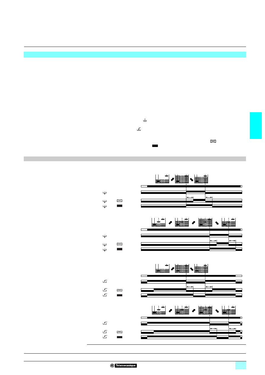
3/111
3
Presentation
(continued)
3
Zelio Control - industrial
measurement and control relays
3
Liquid level control relays RM4 L
The operating principle is based on a change in the resistance measured between immersed
or non-immersed electrodes. Low resistance between electrodes: liquid present. High
resistance between electrodes: no liquid present. The electrodes may be replaced by other
sensors or probes which transmit values representing variations in resistance.
The a.c. measuring voltage which is < 30 V and galvanically insulated from the supply
and contact circuits, ensures safe use and the absence of any electrolysis phenomena.
RM4 relays may be used:
1 For detection of a liquid level, operating with 2 electrodes, one reference electrode and
one high level electrode, or an LA9 RM201 probe. Example: prevention of tank overflow.
1 For regulating a liquid level between a minimum and a maximum level, operating
with 3 electrodes, one reference electrode, one low level electrode and one high level
electrode, or two LA9 RM201 probes.
Example: water tower.
The state of the output relay can be configured:
1 Empty function : the output relay is energised when high level electrode B2 is
immersed and is de-energised when low level electrode B3 is "dry" (1).
1 Fill function : the output relay is energised when the low level electrode is "dry"
and is de-energised when high level electrode is immersed (1).
On model RM4 LA32 a time delay can be set on energisation or de-energisation of
the output relay in order to raise the maximum level function
or to lower the
minimum level function
.
This function also makes it possible to avoid pulsing of the output relay (wave effect)
when operating with 2 electrodes .
Operating principle
Function diagrams
2222 Empty function
26Maximum level detection (2 electrodes or 1 probe LA9 RM201)
26Regulation between a maximum and a minimum level (3 electrodes or 2 probes LA9 RM201)
2222 Full function
26Maximum level detection (2 electrodes or 1 probe LA9 RM201)
26Regulation between a maximum and a minimum level (3 electrodes or 2 probes LA9 RM201)
B1 : reference electrode
B2 : high level electrode
B3 : low level electrode
(1) When operating with 2 electrodes, the high level electrode performs both high and low level functions.
t
t
15/18 25/28
15/16 25/26
15/18 25/28
15/16 25/26
15/18
LA32
LA32
LG01
Ð
15/16
B1
B2
B1
B2
B1
B2
Type
RM4-
Function
switch 3
Time delay
switch 4
U supply
A1/A2
t
t
15/18 25/28
15/16 25/26
15/18 25/28
15/16 25/26
15/18
15/16
B1 B3 B2
B1 B3 B2
B1 B3 B2
B1 B3 B2
LA32
LA32
LG01
Ð
Type
RM4-
Function
switch 3
Time delay
switch 4
U supply
A1/A2
LA32
LA32
LG01
Ð
t
t
15/18 25/28
15/16 25/26
15/18 25/28
15/16 25/26
15/18
15/16
B1
B2
B1
B2
B1
B2
Type
RM4-
Function
switch 3
Time delay
switch 4
U supply
A1/A2
t
t
15/18 25/28
15/16 25/26
15/18 25/28
15/16 25/26
15/18
15/16
B1 B3 B2
B1 B3 B2
B1 B3 B2
B1 B3 B2
LA32
LA32
LG01
Ð
Type
RM4-
Function
switch 3
Time delay
switch 4
U supply
A1/A2
References :
page 3/112
Characteristics :
page 3/113
Dimensions, schemes :
page 3/114
Setting-up :
page 3/115
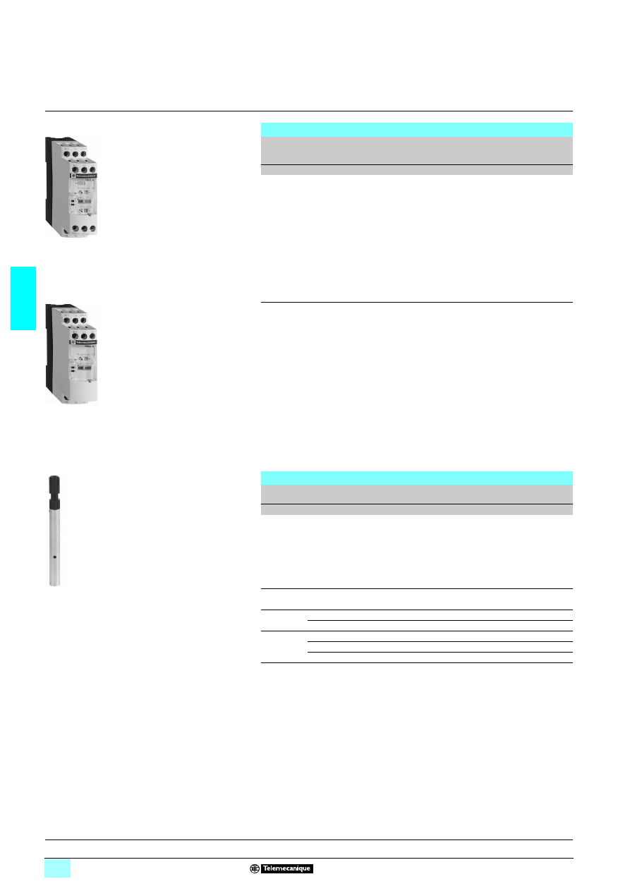
3/112
3
References
3
Zelio Control - industrial
measurement and control relays
3
Liquid level control relays RM4 L
Liquid level control relays
Time delay
Sensitivity
scale
Width
Output
relay
Basic reference, to be
completed by adding
the voltage code (1)
Weight
k
Ω
mm
kg
Without
5…100 22.5
1
C/O
RM4 LG01
2222
0.165
Adjustable
0.1...10 s
0.25 ...5
22.5
2 C/O
RM4 LA32
22
22
22
22
0.165
2.5 ...50
25 ...500
Level control probe for liquid
Type of installation
Maximum operating
temperature
Reference
Weight
°C
kg
Suspended by cable
100
LA9 RM201
0.100
(1) Standard supply voltages
RM4 LG01
Volts
24
110...130 220...240
380...415
1 50/60 Hz
B
F
M
Q
RM4 LA32
Volts
24...240 24
110...130 220...240
380...415
1 50/60 Hz MW
B
F
M
Q
2
MW
–
–
–
–
RM4 LG01
RM4 LA32
LA9 RM201
Presentation :
pages 3/110 and 3/111
Characteristics :
page 3/113
Dimensions, schemes :
page 3/114
Setting-up :
page 3/115
56
10
87
56
10
89
56
10
88
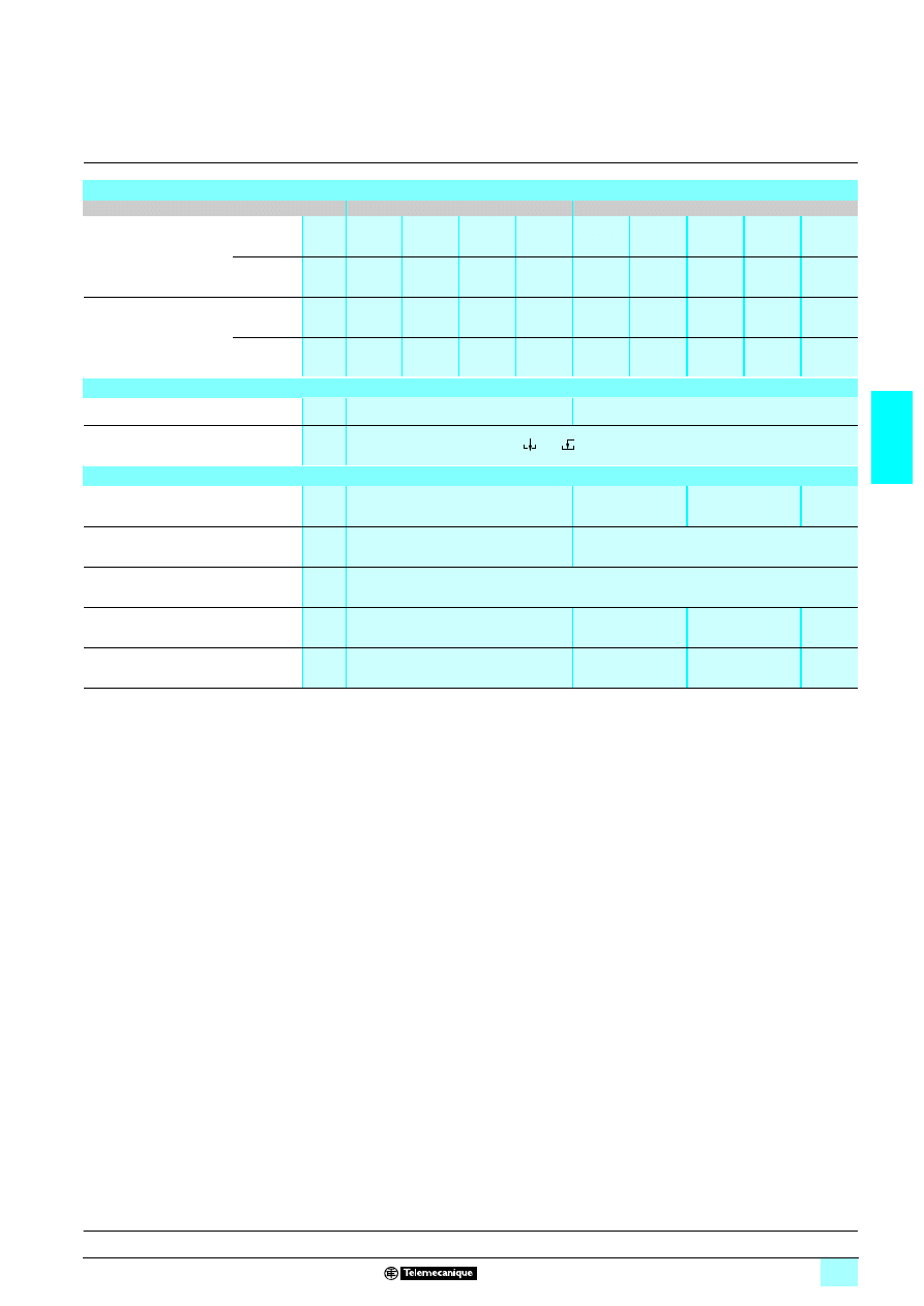
3/113
3
Characteristics
3
Zelio Control - industrial
measurement and control relays
3
Liquid level control relays RM4 L
Power supply circuit characteristics
Relay type
RM4 LG01
RM4 LA32
Rated supply voltage (Un)
1 50/60 Hz
V
24
110...130
220...240
380...415
24...240
24
110...130
220...240
380...415
2
V
–
–
–
–
24...240
–
–
–
–
Average consumption
at Un
1
VA
1.9
2.6
2.4
2.9
2.7
3.1
2.7
2.6
3.4
2
W
–
–
–
–
2.4
–
–
–
–
Output relay and operating characteristics
Number of C/O contacts
1
2
Output relay state
Can be configured by switch: empty
/ fill
Electrode circuit characteristics
(1)
Sensitivity scale
k
Ω
5…100 (adjustable)
0.25…5
2.5…50
25…500
Maximum a.c. electrode voltage
(peak to peak)
V
24
24
Maximum current in the electrodes
mA
1
Maximum cable capacity
nF
10
200
25
4
Maximum cable length
m
100
1000
100
20
(1) The electrodes may also be incorporated in the probes. The probes are normally designed for fixing to a tank by means of a bracket with a seal (closed tanks)
or suspended by their own electrical connecting cable (boreholes, etc.). See page 3/115 “Setting-up” Probe LA9-RM201.
Presentation :
pages 3/110 and 3/111
References :
page 3/112
Dimensions, schemes :
page 3/114
Setting-up :
page 3/115
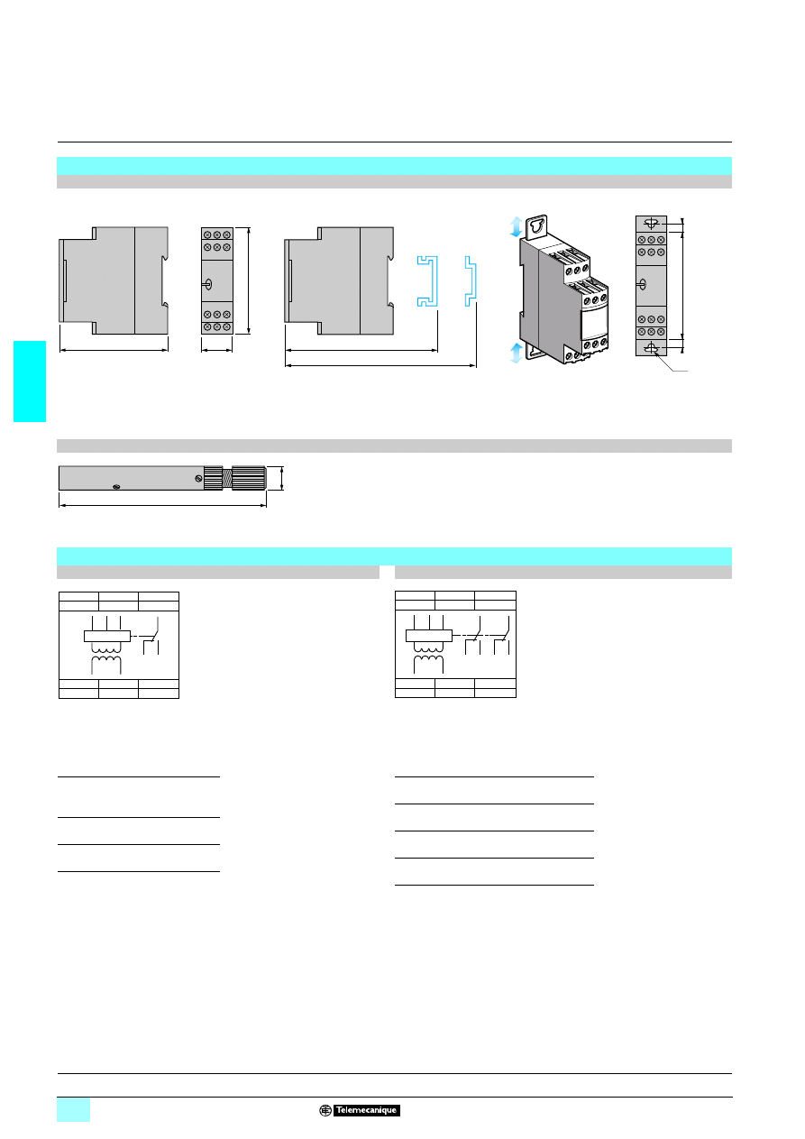
3/114
3
Dimensions,
schemes
3
Zelio Control - industrial
measurement and control relays
3
Liquid level control relays RM4 L
Dimensions
RM4 LG01, LA32
Rail mounting
Screw fixing
Probe LA9 RM201
Connection schemes
RM4 LG01
RM4 LA32
A1-A2
B1, B2, B3
Supply voltage
Electrodes
(see table opposite)
Electrodes and level controlled
B1
Reference or tank earth electrode
15-18
1
st
C/O contact
of the output relay
15-16
B2
High level
25-28
2
nd
C/O contact
of the output relay
25-26
B3
Low level
22,5
78
80
89,5
82
Ø4
6
6
78
150
16
B1
B2
A1
15
B3
18
16
A2
18
15
16
B3
B2
B1
A2
A1
B1
B2
A1
15
B3
25
18
16
A2
28
26
18
15
16
B3
26
28
25
B2
B1
A2
A1
Presentation :
pages 3/110 and 3/111
References :
page 3/112
Characteristics :
page 3/113
Setting-up :
page 3/115
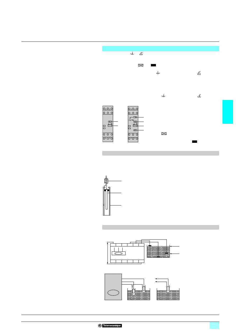
3/115
3
Setting-up
3
Zelio Control - industrial
measurement and control relays
3
Liquide level control relays RM4 L
1 Select the empty /fill function according to the sequence to be performed.
1 If necessary, set potentiometer
1
to minimum (time delay).
1 Set potentiometer
2
to minimum; on RM4-LA, select the lowest sensitivity range
using potentiometer
4
(5
or 5
).
1 With all the electrodes immersed, turn the sensitivity potentiometer towards
maximum until the relay is energised (
function) or de-energised (
function),
then exceed the threshold by about 10 % to compensate for variation in the supply
voltage.
If the relay is not able to energise, a higher sensitivity scale must be used (selector
4
on RM4 LA32) or relay RM4 LG must be replaced by an RM4 LA32 relay and the
adjustment procedure must be started again.
1 Then check that the relay de-energises ( function) or energises ( function) as
soon as electrodes B3 and B2 are out of the liquid. If the relay does not de-energise,
select a lower sensitivity scale.
This probe is of the "suspension" type. It is coaxial, i.e. in addition to the normal
(central) electrode, the stainless steel skirt can also act as earth (reference
electrode), which means that there is no need to install a separate reference probe.
In this way, for controlling one level, only one probe is required instead of 2; for
controlling 2 levels, only 2 probes are required instead of 3.
Setting-up
1 The electrode connection point must be
protected against corrosion by sticking or sealing.
In areas where thunderstorms are likely to occur,
measures must also be taken to protect the
electrode lines.
Note: the high level can be raised by means of the
adjustable time delay from 0.1 to 10 seconds with
function .
The low level can be lowered by means of this
same time delay with function
.
RM4 LG01
RM4 LA32
2
3
R
U
1
2
4
R
U
3
Probe LA9 RM201
The connecting cable must be of the
"2-conductor" type, with common cylindrical PVC
sheath, having a maximum diameter of 6.3 mm.
The skirt also acts as a "calming chamber", so
avoiding inaccuracy due to an agitated surface of
the liquid (waves).
Maximum operating temperature: 100 °C.
Probe LA9 RM201 can also be fixed on various
containers (cisterns, tanks, ...) by means of a
bracket or other suitable fixing device.
LA9 RM201
2-conductor cable in
cylindrical sheath
(max Ø 6.3 mm)
Level electrode
Reference electrode
(skirt)
Connection examples
2222 Control by electrodes
2222 Control by probes
B3
B2
B1
A1
B2
B3
B1
A2
High level
Low level
S
u
pply volta
g
e
B1
B2
B3
B2
B1
RM4 LG01
2 levels
1 level
Presentation :
pages 3/110 and 3/111
References :
page 3/112
Characteristics :
page 3/113
Dimensions, schemes :
page 3/114
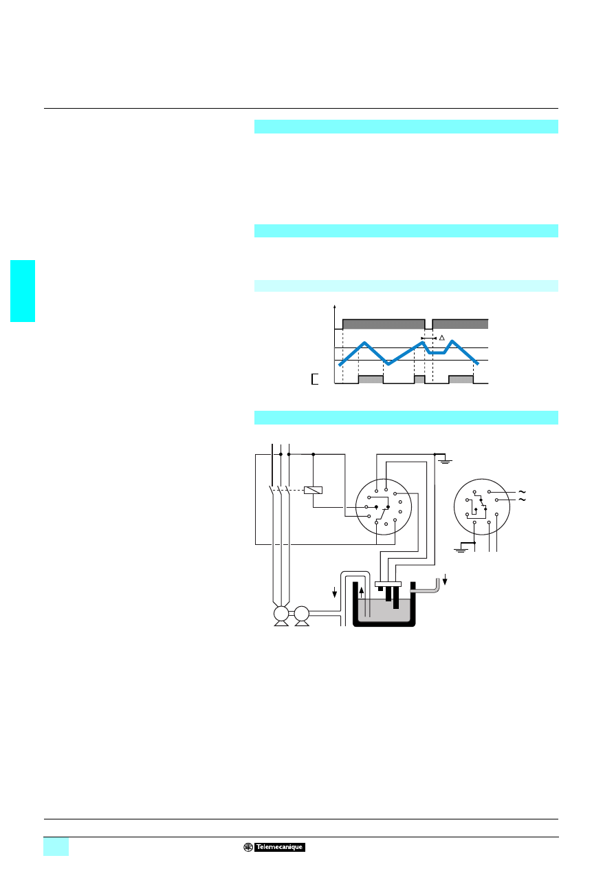
3/116
3
Functions,
schemes
3
Zelio Control - industrial
measurement and control relays
3
Plug-in liquid level control relays RM 84 870
The output relay changes state when the level of the liquid reaches the maximum
level probe, with the minimum level probe submerged. It returns to its initial state
when the minimum level probe is no longer in contact with the liquid.
1 Controlling the levels of conductive liquids
1 Regulation of two thresholds:
2 minimum,
2 maximum.
1 Emptying function.
1 Plug-in, 8 or 11-pin.
1 Sensitivity adjustable from 5 kΩ to 100 kΩ.
Operating principle
Control of maximum and/or minimum levels of conductive liquids (tap water, sea
water, waste water, chemical solutions, coffee ...).
The operating principle is based on measurement of the apparent resistance of the
liquid between two submerged probes. When this value is less than the threshold
setting on the front panel of the device, the output relay changes state. To avoid
electrolytic phenomena, an a.c. current runs across the probes.
Applications in the food-processing, chemical industries, etc.
Regulation of two levels, minimum/maximum
Emptying control
Connection scheme
For RM 84 870 807 (special 11-pin base fitting), pin 5 must be connected to “a”
(maximum) and pin 7 must be connected to “c” (common).
Un
T
Energisation of the
device
Level being controlled
Emptying function
Max. level
Min. level
Output relay
Down
R S T
M
P
1
2
3
4
5
6
7
8
10
9
11
1
2
3
4
5
6
7
8
a
b
c
c
b a
a - Maximum
b - Minimum
c - Common
8-pin
11-pin
Input
References :
page 3/117
Characteristics :
page 3/117
Dimensions :
page 3/117
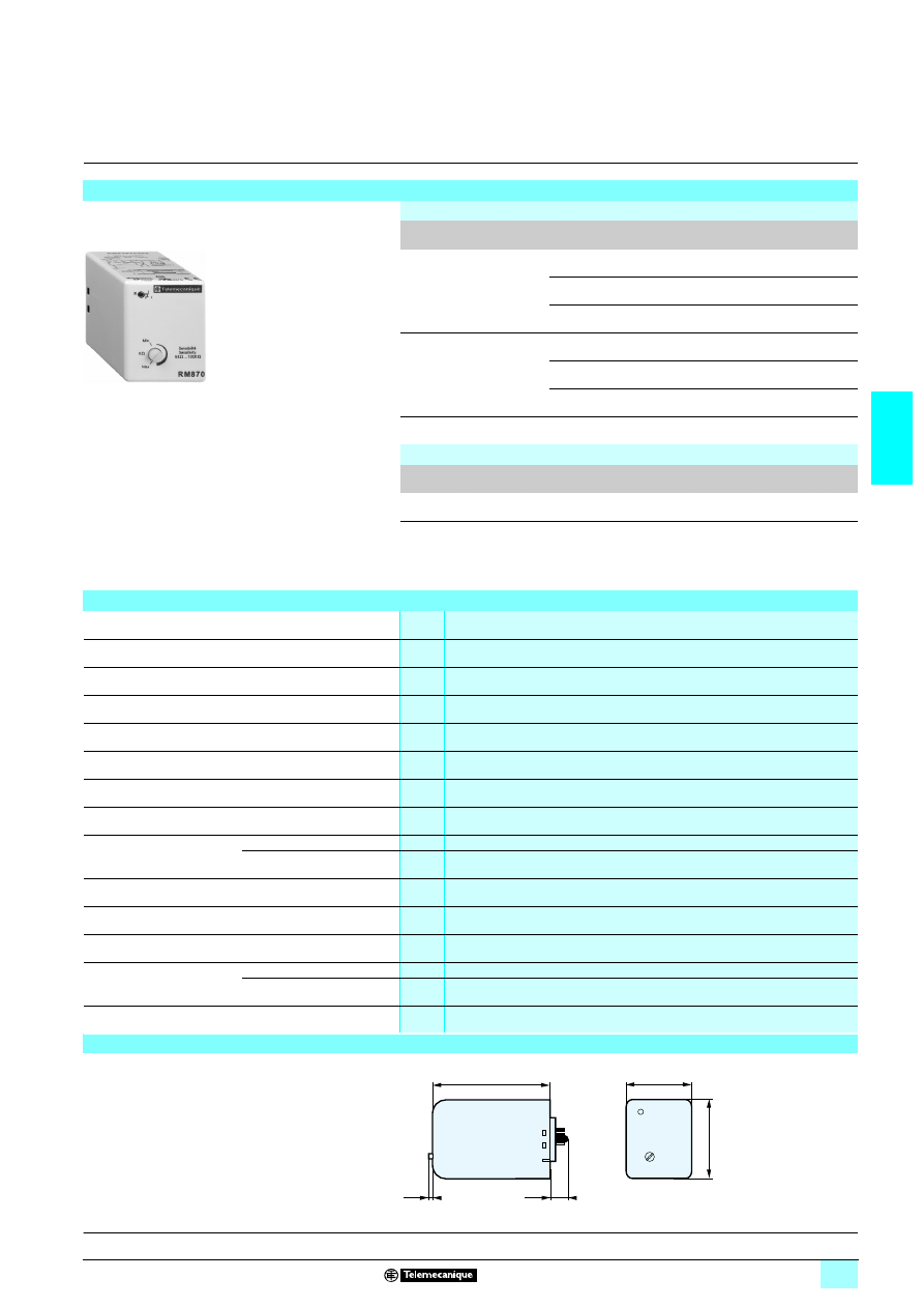
3/117
3
References,
characteristics,
dimensions
3
Zelio Control - industrial
measurement and control relays
3
Plug-in liquid level control relays RM 84 870
References
Liquid level control relays
Number of pins
Voltage
Reference
Weight
kg
8-pin
1424 V
RM 84 870 301
0.140
14120 V
RM 84 870 303
0.140
14230 V
RM 84 870 304
0.140
11-pin
1424 V
RM 84 870 306
0.140
14120 V
RM 84 870 308
0.140
14230 V
RM 84 870 309
0.140
Special 11-pin base fitting
14230 V
RM 84 870 807
0.190
Accessories
Description
Sold in lots of
Unit reference
Weight
kg
11-pin socket
10
RUZ 1A
0.067
Note: The probe cable, with a maximum length of 100 metres (recommended probes,
see page 3/58) need not be screened, but it is inadvisable to fit it in parallel with the power supply
cables.
Screened cable may be used, with the screening connected to the common.
Characteristics
Supply voltage Un
V
1 24, 120, 230 (50/60 Hz)
Operating range
0.85…1.15 x Un
Maximum power consumption
VA
3
Sensitivity adjustment
k
Ω
5…100
Measurement accuracy
(at maximum sensitivity)
0…+ 30 %
Maximum electrode voltage
V
1 24 (50/60 Hz)
Maximum electrode current
mA
1 (50/60 Hz)
Maximum cable capacity
nF
10
Response time
High level
ms
300
Low level
ms
500
Output relay (to meet AC-1 requirements, resistive load)
1 C/O contact, AgCdO
1 8 A max.
Galvanic isolation via transformer
(4 kV, 8 mm creepage distance)
Class II VDE 0551
Isolation of contacts and electrodes from the supply
kV
1 2.5
Temperature limits
Operation
°C
- 20…+ 60
Storage
°C
- 30…+ 70
Product certifications
c UL us, CSA
Dimensions
RM 84 870 303
56
10
08
70
39
50
16
3,5
Functions :
page 3/116
Scheme :
page 3/116
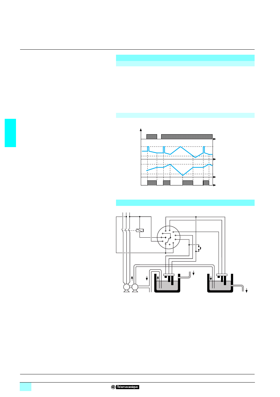
3/118
3
Functions,
scheme
3
Zelio Control - industrial
measurement and control relays
3
Plug-in liquid level control relays RM 84 870,
combined fill/empty functions
For RM 84 870 808 (special 11-pin base fitting), pin 5 must be connected to “a”
(maximum) and pin 7 must be connected to “c” (common).
1 Controlling the levels of conductive liquids.
1 Combined fill/empty function.
1 Combined regulation of emptying a well and filling a
tank.
1 Plug-in, 11-pin.
1 Output relay state indication LED.
1 Sensitivity adjustable from 5 kΩ to 100 kΩ
Operating principle
Combined fill/empty function
The output relay changes state when the level of the liquid in the tank reaches the
maximum level probe, with the minimum level probe submerged. It returns to its initial
state when the minimum level probe is no longer in contact with the liquid.
When the level of the liquid in the well reaches the minimum level probe, the pump
stops.
If, on energisation or after a power cut, the maximum level probe in the tank is above
the liquid level, reset the device by pressing button BP.
Emptying control
(1) Pushbutton
Connection scheme
Un
(1)
(1)
(1)
Max. level
Well
Min. level
Output relay
Max. level
Tank
Min. level
R S T
M
P
1
2
3
4
a
b
c
5
6
7
8
10
9
11
Tank
Well
Pushbutton
Output
Input
a : maximum
b : minimum
c : common
References :
page 3/119
Characteristics :
page 3/119
Dimensions :
page 3/119
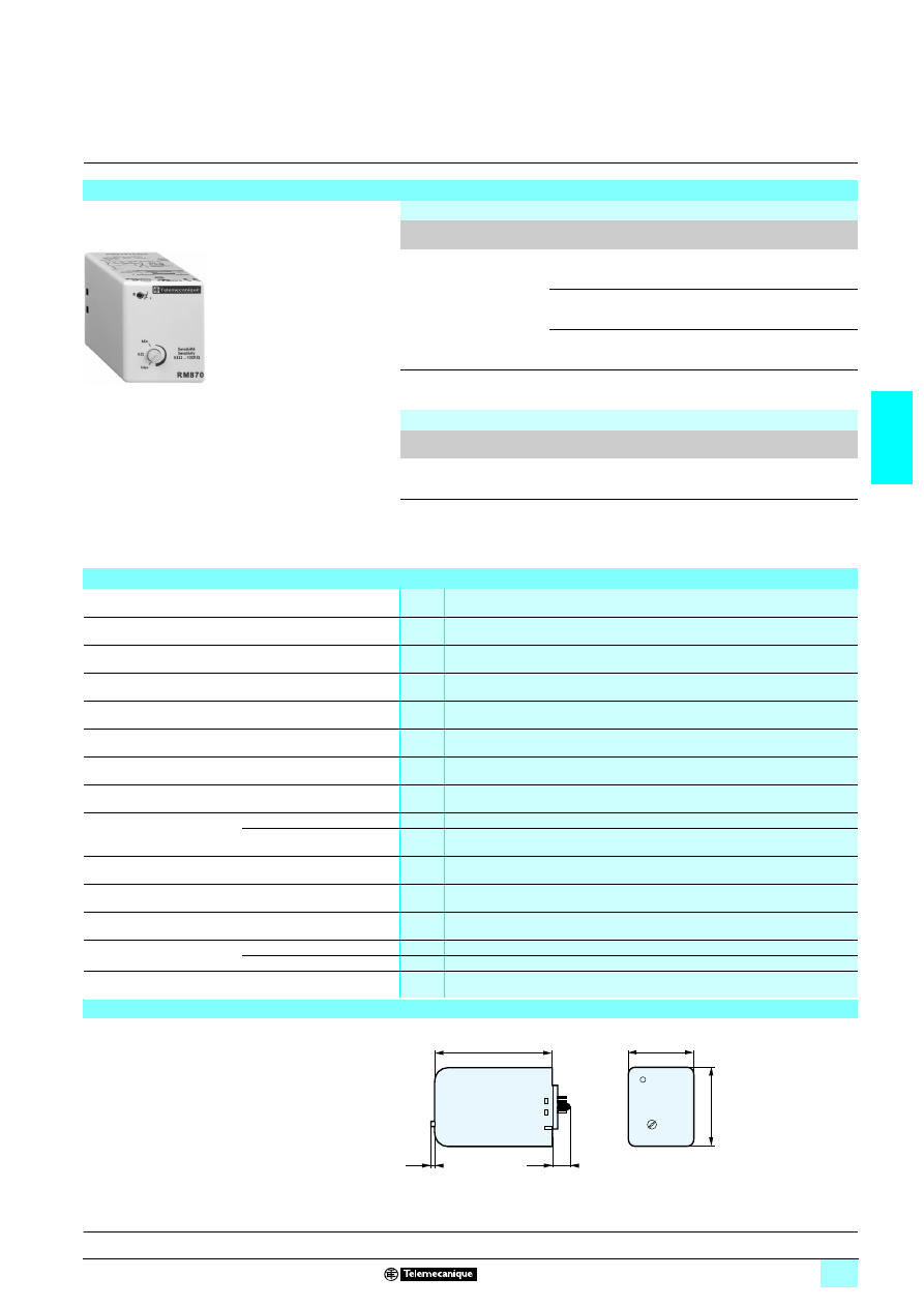
3/119
3
References,
characteristics,
dimensions
3
Zelio Control - industrial
measurement and control relays
3
Plug-in liquid level control relays RM 84 870,
combined empty/fill functions
References
Liquid level control relays
Number of pins
Voltage
Reference
Weight
kg
11-pin
1424 V
RM 84 870 401
0.140
14120 V
RM 84 870 403
0.140
14230 V
RM 84 870 404
0.140
Special 11-pin base fitting
14230 V
RM 84 870 808
0.190
Accessories
Description
Sold in lots of
Unit reference
Weight
kg
11-pin socket
10
RUZ 1A
0.067
Note: The probe cable, with a maximum length of 100 metres (recommended probes,
see page 3/58) need not be screened, but it is inadvisable to fit it in parallel with the power supply
cables.
Screened cable may be used, with the screening connected to the common.
Characteristics
Supply voltage Un
V
1 24, 120, 230 (50/60 Hz)
Operating range
0.85…1.15 x Un
Maximum power consumption
VA
3
Sensitivity adjustment
k
Ω
5…100
Measurement accuracy
(at maximum sensitivity)
0…+ 30 %
Maximum electrode voltage
V
1 24 (50/60 Hz)
Maximum electrode current
mA
1 (50/60 Hz)
Maximum cable capacity
nF
10
Response time
High level
ms
300
Low level
ms
500
Output relay (to meet AC-1 requirements, resistive load)
1 C/O contact, AgCdO
1 8 A max.
Galvanic isolation via transformer
(4 kV, 8 mm creepage distance)
Class II VDE 0551
Isolation of contacts and electrodes from the supply
kV
1 2.5
Ambient air temperature
Operation
°C
- 20…+ 60
Storage
°C
- 30…+ 70
Product certifications
c UL us, CSA
Dimensions
RM 84 870 40
1
56
10
09
70
39
50
16
3,5
Functions :
page 3/118
Scheme :
page 3/118
Wyszukiwarka
Podobne podstrony:
ch3
ch3 (2)
Ch3 3 6 ProductionOfForestEnergy
Ch3 Q1
ch3
Biochemia 3, aminokwasy, metanol: CH3-OH, etanol: C2H5-OH, Propyl: C3H7-OH, Butanol: C4H9-OH, Pentan
Ch3 Q4
Ch3 Q6
CH3 (3)
Ch3 Q2
cisco2 ch3 focus LWIJRK6VCQAXIIIE3LHUL753BUY5NGJMRCTRJQQ
Biochemia 4, kwasy karboksylowe, metanol: CH3-OH, etanol: C2H5-OH, Propyl: C3H7-OH, Butanol: C4H9-OH
ch3
cisco2 ch3 concept CFDTCGGIQW4KGH7I6FTQ4JMKT4VRXEZHT3GKDOA
Ch3 PowerPlantEconomicsAndVariableLoadProblem
ch3 revised id 110497 Nieznany
ch3 Timing Overhead
routing statyczny, EiT, Protokoły rutingu, Ruting statyczny CH3
więcej podobnych podstron