

7/0

7/1
Contents
0
7
7 - Phaseo power supplies and
transformers
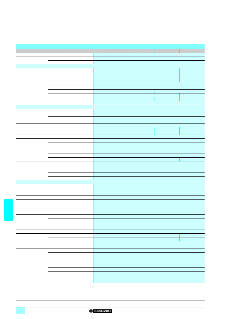
Selection guide: Phaseo power supplies
Modular, Optimum and universal ranges . . . . . . . . . . . . . . . . . . . . . . . . page 7/2
Selection guide: Phaseo power supplies
Dedicated, Rectified and AS-Interface ranges . . . . . . . . . . . . . . . . . . . . page 7/4
Selection guide: Phaseo transformers . . . . . . . . . . . . . . . . . . . . . . . . . . page 7/6
Phaseo regulated switch mode power supplies
1 Presentation . . . . . . . . . . . . . . . . . . . . . . . . . . . . . . . . . . . . . . . . . . . . . . page 7/8
1 Phaseo Modular range power supplies . . . . . . . . . . . . . . . . . . . . . . . . . page 7/12
1 Phaseo Optimum range power supplies. . . . . . . . . . . . . . . . . . . . . . . . page 7/18
1 Phaseo Universal range power supplies
2 Presentation, description . . . . . . . . . . . . . . . . . . . . . . . . . . . . . . . . . . page 7/24
2 References . . . . . . . . . . . . . . . . . . . . . . . . . . . . . . . . . . . . . . . . . . . . page 7/31
2 Converter modules . . . . . . . . . . . . . . . . . . . . . . . . . . . . . . . . . . . . . . page 7/34
2 Function modules
Solutions to microbreaks and power outages . . . . . . . . . . . . . . . . . . page 7/38
Redundancy solution . . . . . . . . . . . . . . . . . . . . . . . . . . . . . . . . . . . . page 7/46
Solution for discriminating protection of the application . . . . . . . . . . page 7/50
1 Phaseo dedicated range power supplies. . . . . . . . . . . . . . . . . . . . . . . . page 7/54
1 Phaseo AS-Interface range power supplies . . . . . . . . . . . . . . . . . . . . . page 7/60
Rectified and filtered power supplies
1 Phaseo Rectified range power supplies . . . . . . . . . . . . . . . . . . . . . . . . page 7/64
Safety and isolation transformers
1 Phaseo Economic range of transformers . . . . . . . . . . . . . . . . . . . . . . . page 7/74
1 Phaseo Optimum range of transformers . . . . . . . . . . . . . . . . . . . . . . . . page 7/75
1 Phaseo Universal range of transformers . . . . . . . . . . . . . . . . . . . . . . . . page 7/76
Substitution
1 Substitution table . . . . . . . . . . . . . . . . . . . . . . . . . . . . . . . . . . . . . . . . . . page 7/86
7/2
7
Selection guide
7
Power supplies and transformers
7
Power supplies for DC control circuits
Phaseo power supplies
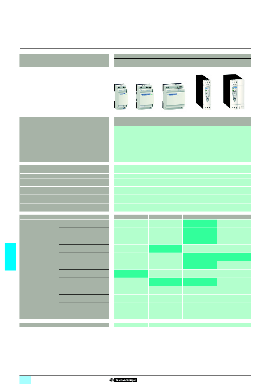
Power supplies
Regulated switch mode
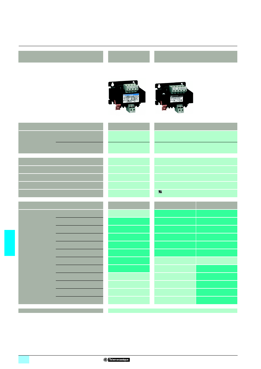
Phaseo Modular range and Optimum range industrial power supplies
Input voltage
100...240 V
12
120...250 V
3 (see pages 7/13 and 7/14)
Connection to
world-wide line supplies
United States
- 120 V (in phase-to-neutral)
- 240 V (in phase-to-phase)
Single-phase (N-L1) or 2-phase (L1-L2) connection
Europe
- 230 V (in phase-to-neutral)
- 400 V (in phase-to-phase)
Single-phase (N-L1) connection
United States
- 277 V (in phase-to-neutral)
- 480 V (in phase-to-phase)
–
IEC 61000-3-2 conformity
Yes for ABL 7RP, not for ABL 8REM and not applicable for ABL 8MEM and ABL 7RM
Protection against undervoltage (U > 19 V)
Yes
Protection against overloads and short-circuits
Yes, voltage detection. Automatic restart on elimination on the fault
Diagnostic relay
–
Compatibility with function modules
–
Power reserve (Boost)
1,25 to 1,4 In during 1 minute, depending on model (with ABL 8MEM)
No
Output voltage
5 V
3
12 V
3
24 V
3
48 V
3
Output current
0.3 A
ABL 8MEM24003
(Modular)
0.6 A
ABL 8MEM24006
(Modular)
1.2 A
ABL 8MEM24012
(Modular)
2 A
ABL 8MEM12020
(Modular)
2.5 A
ABL 7RM24025
(Modular)
ABL 7RP4803
(Optimum)
3 A
ABL 8REM24030
(Optimum)
4 A
ABL 8MEM05040
(Modular)
5 A
ABL 7RP1205
(Optimum)
ABL 8REM24050
(Optimum)
6 A
10 A
20 A
40 A
Pages
7/17
7/17 (Modular) and 7/23 (Optimum)
7/23
(1) Except ABL 8RPM24200.
12100...120 V and 12200...240 V.
(2)
1/12converter module, requires to be associated with the Phaseo Universal range power supply.
7/3
7
7
7
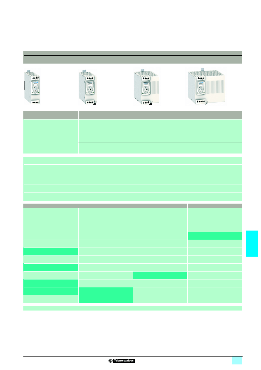
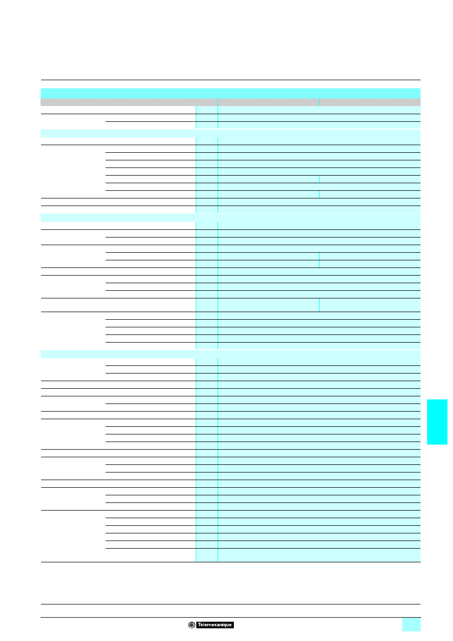
Regulated switch mode
Phaseo Universal range industrial power supplies
100...120 V
12and 200...500 V 1 (1) 380...500 V 12
24 V
3
Single-phase (N-L1) or 2-phase (L1-L2)
connection
–
–
3-phase (L1-L2-L3) connection
–
3-phase (L1-L2-L3) connection
–
Yes
–
Yes
–
Yes, current limitation or undervoltage detection
Yes, current limitation
Yes, depending on model
Yes with buffer module, battery and battery check modules, redundancy module and discriminating downstream protection module
1,5 In during 4 secondes
No
24 V
3
5 V
3
7...12 V
3
ABL 8DCC12020 (2)
ABL 8RPS24030
ABL 8RPS24050
ABL 8DCC05060 (2)
ABL 8RPS24100
ABL 8RPM24200
ABL 8WPS24200
ABL 8WPS24400
7/31
7/36
7/4
7
Selection guide
7
Power supplies and transformers
7
Power supplies for DC control circuits
Phaseo power supplies
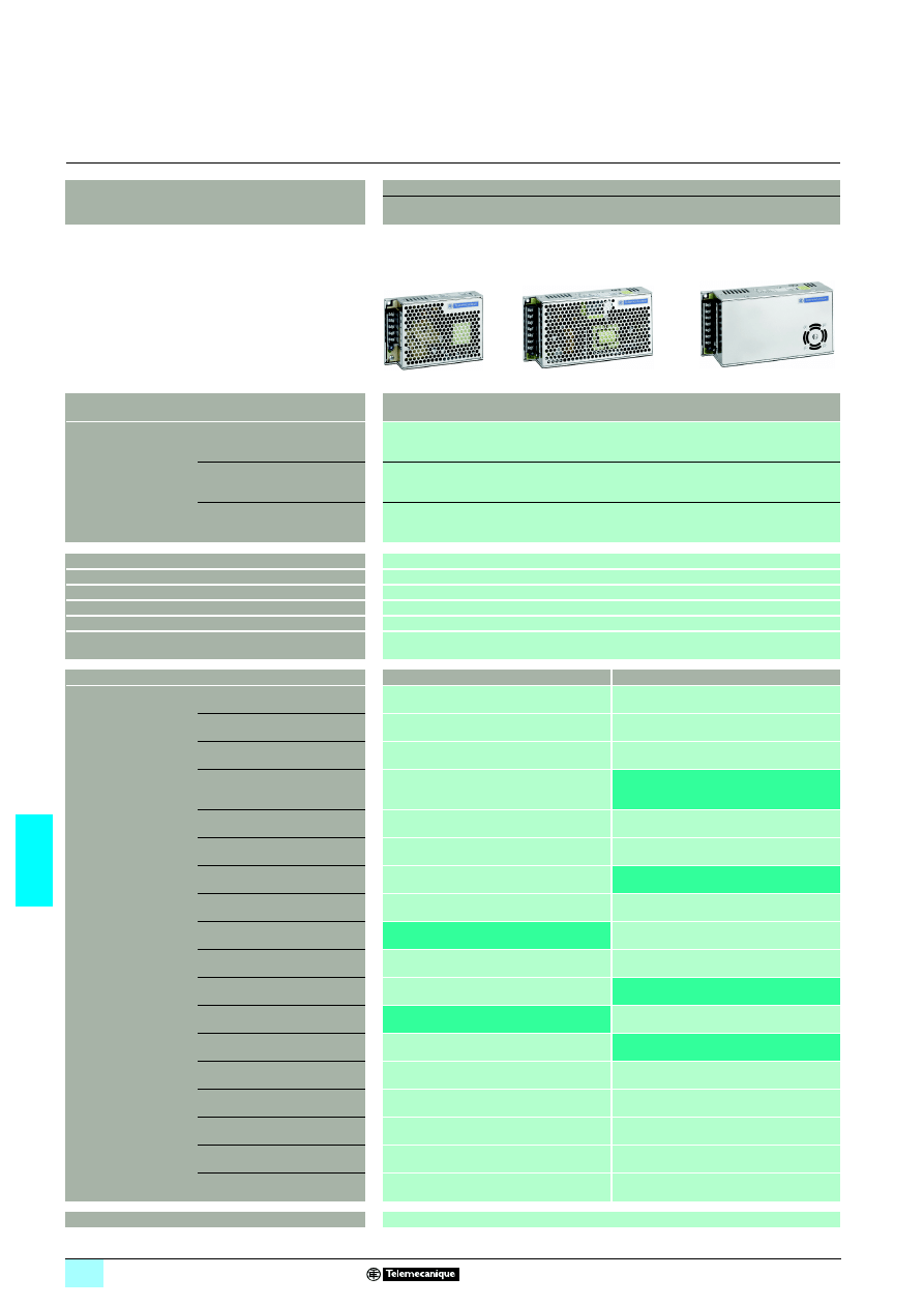
Power supplies
Regulated switch mode
Phaseo Dedicated range power supplies for repetive machines
Input voltage
100...240 V
12
120...370 V
3 (see page 7/55)
Connection to
world-wide line supplies
United States
- 120 V (in phase-to-neutral)
- 240 V (in phase-to-phase)
Single-phase (N-L1) or 2-phase (L1-L2) connection
Europe
- 230 V (in phase-to-neutral)
- 400 V (in phase-to-phase)
Single-phase (N-L1)
–
United States
- 277 V (in phase-to-neutral)
- 480 V (in phase-to-phase)
Single-phase (N-L1)
–
IEC 61000-3-2 conformity
Yes for ABL 1RP, not applicable for ABL1REM24025/12050
Protection against undervoltage (U > 19 V)
–
Protection against overloads and short-circuits
Yes, voltage detection. Automatic restart on elimination on the fault
Diagnostic relay
–
Compatibility with function modules
–
Power reserve (Boost)
No
Output voltage
12 V
3
24 V
3
Output current
0.5 A
1 A
2 A
2.5 A
ABL 1REM24025
3 A
4 A
4.2 A
ABL 1R
1111M24042
4.8 A
5 A
ABL 1REM12050
6 A
6.2 A
ABL 1R
1111M24062
8.3 A
ABL 1RPM12083
10 A
ABL 1R
1111M24100
15 A
20 A
30 A
40 A
60 A
Pages
7/58
7/5
7
7
7
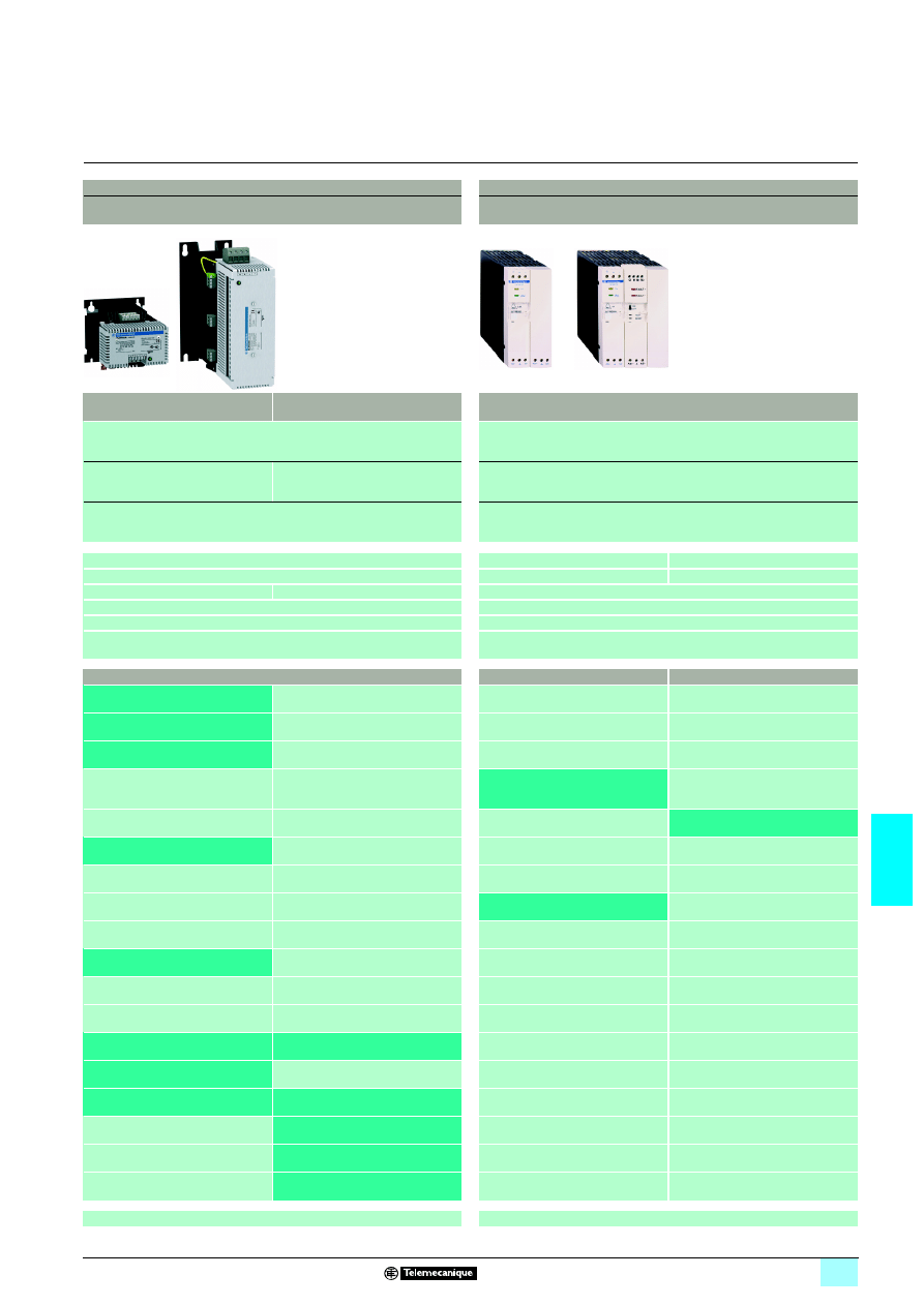
Rectified and filtered
Regulated switch mode
Phaseo Rectified range for harsh environment
Phaseo range AS-Interface for AS-Interface cabling system
230 V
1 and 400 V 1
400 V
1
100...240 V
12
–
Single-phase (N-L1) connection
Single-phase (N-L1) or
2-phase (L1-L2) connection
3-phase (L1-L2-L3) connection
Single-phase (N-L1) connection
–
–
Yes
No
Yes
No
–
Yes
Yes depending on model, by fuse
Yes, by external protection
Yes
No
–
No
–
No
No
24 V
3
30 V
3
24 V
3
ABL 8FEQ24005
ABL 8FEQ24010
ABL 8FEQ24020
ASI ABLB3002
ASI ABLD3002 (1)
ASI ABLM3024 (2)
ASI ABLM3024 (2)
ABL 8FEQ24040
ASI ABLB3004 (2)
ASI ABLD3004 (1)
ABL 8FEQ24060
ABL 8FEQ24100
ABL 8TEQ24100
ABL 8FEQ24150
ABL 8FEQ24200
ABL 8TEQ24200
ABL 8TEQ24300
ABL 8TEQ24400
ABL 8TEQ24600
7/70
7/63
(1) With earth fault detection.
(2) One output 30 V
1 and one output 24 V 1 ± 5 %.
7/6
7
Selection guide
7
Power supplies and transformers
7
Transformers for AC control circuits
Phaseo transformers
Transformers for AC control circuits
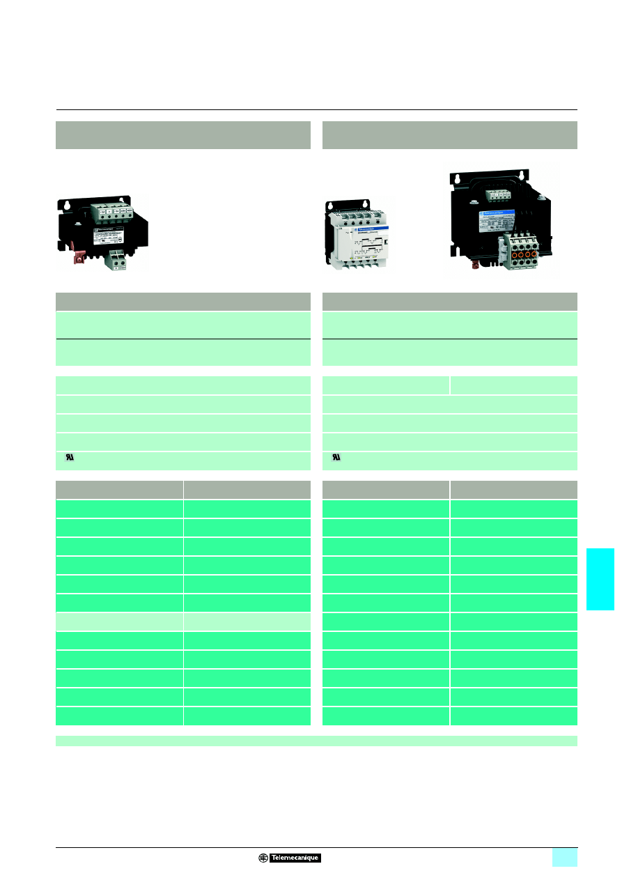
Phaseo Economic range
transformers
Phaseo Optimum range transformers
Tension d’entrée
230 V
1, ± 15 V
230 V
1 and 400 V 1, ± 15 V
Connection to
world-wide line supplies
United States
- 120 V (in phase-to-neutral)
- 240 V (in phase-to-phase)
–
–
–
2-phase (L1-L2) connection
Europe
- 230 V (in phase-to-neutral)
- 400 V (in phase-to-phase)
Single-phase (N-L1)
connection
Single-phase (N-L1) connection
Applications
Safety transformer (SELV)
Safety transformer (SELV)
Secondary winding
Single winding
Single winding
Signalling
–
–
Standards
IEC 61558-2-6,
EN 61558-2-6
IEC 61558-2-6, EN 61558-2-6, UL 506
Certifications
–
C
us
Output voltage
24 V
1
12 V
1
24 V
1
Nominal power
25 VA
ABL 6TS02J
ABL 6TS02B
40 VA
ABT 7ESM004B
ABL 6TS04J
ABL 6TS04B
63 VA
ABT 7ESM006B
ABL 6TS06J
ABL 6TS06B
100 VA
ABT 7ESM010B
ABL 6TS10J
ABL 6TS10B
160 VA
ABT 7ESM016B
ABL 6TS16J
ABL 6TS16B
250 VA
ABT 7ESM025B
ABL 6TS25J
ABL 6TS25B
320 VA
ABT 7ESM032B
400 VA
ABT 7ESM040B
ABL 6TS40B
630 VA
ABL 6TS63B
1 000 VA
ABL 6TS100B
1 600 VA
ABL 6TS160B
2 500 VA
ABL 6TS250B
Pages
7/82
7/7
7
7
7
Phaseo Optimum range transformers
Phaseo Universal range transformers
230 V
1 and 400 V 1, ± 15 V
230 V
1 and 400 V 1, ± 15 V
–
2-phase (L1-L2) connection
–
2-phase (L1-L2) connection
Single-phase (N-L1) connection
Single-phase (N-L1) connection
Isolation transformer
Safety transformer (SELV)
Isolation transformer
Single winding
Double winding
–
Presence of input voltage by LED (up to 320 VA)
IEC 61558-2-6, EN 61558-2-6, UL 506
IEC 61558-2-6, EN 61558-2-6, UL 506
C
us
C
us, ENEC
115 V
1
230 V
1
2 x 24 V
1
2 x 115 V
1
ABL 6TS02G
ABL 6TS02U
ABT 7PDU002B
ABT 7PDU002G
ABL 6TS04G
ABL 6TS04U
ABT 7PDU004B
ABT 7PDU004G
ABL 6TS06G
ABL 6TS06U
ABT 7PDU006B
ABT 7PDU006G
ABL 6TS10G
ABL 6TS10U
ABT 7PDU010B
ABT 7PDU010G
ABL 6TS16G
ABL 6TS16U
ABT 7PDU016B
ABT 7PDU016G
ABL 6TS25G
ABL 6TS25U
ABT 7PDU025B
ABT 7PDU025G
ABT 7PDU032B
ABT 7PDU032G
ABL 6TS40G
ABL 6TS40U
ABT 7PDU040B
ABT 7PDU040G
ABL 6TS63G
ABL 6TS63U
ABT 7PDU063B
ABT 7PDU063G
ABL 6TS100G
ABL 6TS100U
ABT 7PDU100B
ABT 7PDU100G
ABL 6TS160G
ABL 6TS160U
ABT 7PDU160B
ABT 7PDU160G
ABL 6TS250G
ABL 6TS250U
ABT 7PDU250B
ABT 7PDU250G
7/82

7/8
7
Presentation
7
Power supplies and transformers
7
Power supplies for DC control circuits
Phaseo regulated switch mode power supplies
The Phaseo electronic switch mode power supply offer is designed to provide the DC
voltage necessary for the PLC and automation system equipment control circuits.
Comprising five ranges:
23Modular, Optimum and Universal for common applications
23AS-Interface for the AS-Interface cabling system
23Dedicated for repetitive equipment
the Phaseo offer meets all the needs encountered in industrial, commercial and
residential applications. With phase-to-neutral (N-L1), phase-to-phase (L1-L2) or
3-phase (L1-L2-L3) connection to the line supply, these electronic switch mode
power supplies provide a quality of output current that is suitable for the loads
supplied and compatible with the line supply available in the equipment. Clear
guidelines are given for selecting protection devices which are often used with them,
and thus a comprehensive solution is provided that can be used in total safety.
Phaseo switch mode power supplies are totally electronic and their output voltage is
regulated. The use of electronics makes it possible to significantly improve the
performance of these power supplies, which offer:
1 Very compact size
1 Integrated overload, short-circuit, overvoltage and undervoltage protection (1)
1 A very wide input voltage range for the Universal range
1 A high degree of output voltage stability
1 Good performance
1 Diagnostics via LED indicators on the front panel
1 Remote diagnostics via a relay contact for the Universal range
Phaseo power supplies deliver a stabilized
4 output3voltage that is precise to 3%,
whatever the load from a
5 line supply, within the ranges of:
1 For Modular, Optimum, Dedicated and AS-Interface ranges:
23100 to 240 V 5 for phase-to-neutral (N-L1) or phase-to-phase (L1- L2) connection
1 For the Universal range:
2385 to 550 V 5 for phase-to-neutral (N-L1) or phase-to-phase (L1- L2) connection
23360 to 550 V 5 for 3-phase connection (L1-L2-L3)
Conforming to IEC standards and UL, CSA, TÜV and CTick certified, they are
suitable for industrial use. The inclusion of overload and short-circuit protection
makes downstream protection unnecessary if discrimination is not required. To
provide discrimination whenever faults occur, it is advisable to use discriminating
electronic downstream protection modules.
Phaseo power supplies also incorporate:
1 An output voltage adjustment potentiometer in order to be able to compensate for
any line voltage drops in installations with long cable runs
1 Direct mounting on 35 mm 6 rails, optional on Dedicated range (2)
(1) The inclusion of overload and short-circuit protection makes downstream protection
unnecessary if discrimination is not required (see page 7/50).
(2) The Optimum and AS-Interface ranges can also take 75 mm
4 rails.
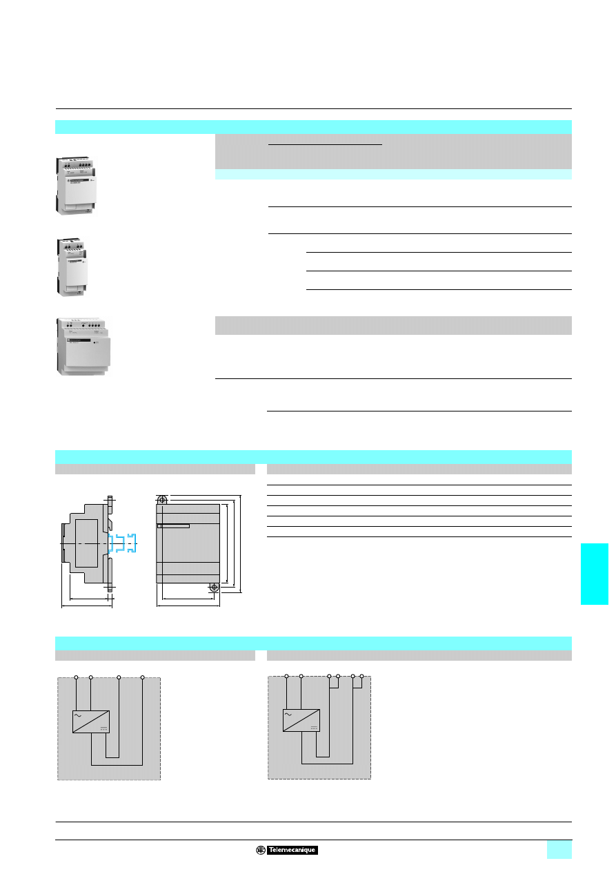
Presentation
Phaseo switch mode power supplies
7/9
7
Presentation
(continued)
7
Power supplies and transformers
7
Power supplies for DC control circuits
Phaseo regulated switch mode power supplies
Phaseo regulated switch mode industrial supplies are offered in three ranges
(Modular, Optimum and Universal), complemented by the range for the AS-Interface
cabling system and the Dedicated range for repetitive machines:
The Phaseo Modular range meets all the needs of simple automation systems with
power ratings from 7 to 60 W and an output voltage of 5 V
4, 12 V 4 or 24 V 4.
The shape and compact nature of its casing mean that it can be incorporated either
in a modular panel or mounted on a
6 rail in a cabinet. Direct mounting on a panel
(using its two retractable lugs) and the choice of wires exiting at the top or bottom
(except for the ABL 7RM24025 model) make it an easy product to integrate.
The Phaseo Optimum range is the low-cost solution for applications supplied in
12 V
4, 24 V 4 or 48 V 4 and requiring currents between 3 and 5 A.
The Optimum range of Phaseo power supplies delivers a voltage that can guarantee
the PLC logic states. In the event of an overload the power supply protection trips so
that, once the fault has been eliminated, the power supply reverts to its nominal state.
Since the Optimum range of Phaseo power supplies does not have PFC (Power
Factor Correction), they do not meet the requirements of standard EN 61000-3-2
(except for AB 7RP1205/7RP4803 models).
The Universal range of Phaseo power supplies covers power ratings from 72 to
960 W in 24 V
4 and adapts to the majority of power distribution systems used
throughout the world. The same power supply can thus be connected
phase-to-neutral (N-L1) or phase-to-phase for line supplies ranging from 100 V
5
to 500 V
5 nominal. In addition, this range offers:
1 Diagnostic functions (local or remote)
1 User choice of operating mode in the event of an overload (current limiting or stop)
1 Function modules to ensure continuity of service:
23Protection against microbreaks or prolonged outages by means of the Buffer
module and Battery check modules
23Paralleling and redundancy functions by means of the Redundancy module
23Discriminating protection against application overloads by means of discriminating
electronic downstream Protection modules
1 A power reserve (boost function) for absorbing the transient current peaks
required by the application
With the Universal range of power supplies, it is possible to satisfy the need for
auxiliary voltage (5 V
4 to 15 V 4) using 4/4 Converter modules.
The incorporation of a PFC (Power Factor Correction) input filter reduces harmonic
pollution to a minimum level across the entire Universal range, ensuring compliance
with the requirements of standard EN 61000-3-2.
The 72 and 144 W AS-Interface range of Phaseo power supplies is designed to
deliver a voltage of 30 V
4, which is a prerequisite for the AS-Interface cabling
system. These electronic switch mode power supplies with phase-to-neutral (N-L1)
connection ensure the quality of the output current in accordance with the electrical
characteristics and in compliance with standard EN 50295.
The Dedicated range of Phaseo power supplies from 60 to 240 W is designed for
integration in repetitive equipment requiring a voltage of 12 V
4 or 24 V 4. These
electronic switch mode power supplies, with phase-to-neutral (N-L1) connection,
with or without anti-harmonic filter and UL 508, CSA and TÜV certified, meet all the
needs encountered in commercial machines and standard catalog machines.
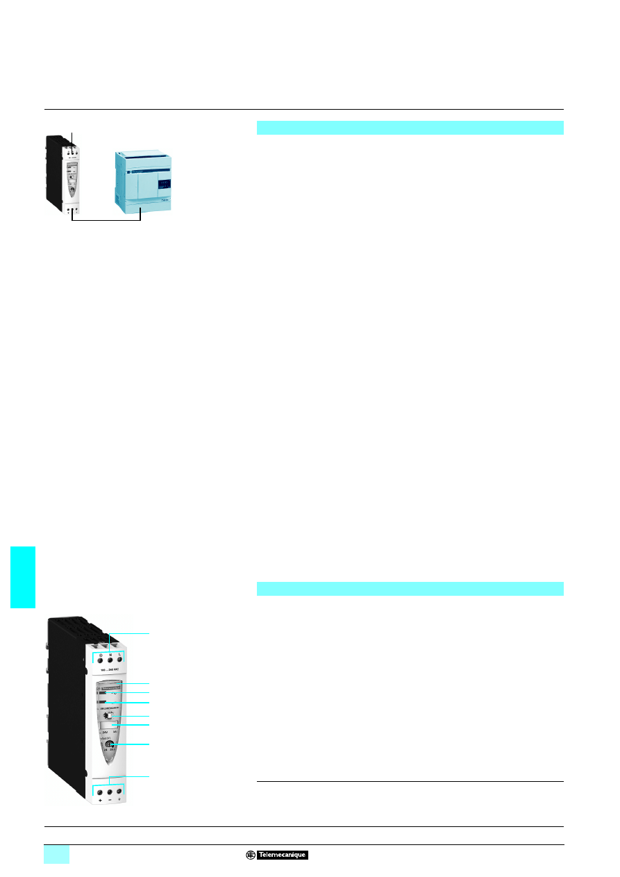
Presentation
(continued)
Phaseo switch mode power supplies
(continued)
Phaseo Modular range
ABL 8MEM12020
Phaseo Optimum range
ABL 8REM24030
Phaseo Universal range
ABL 8RPS24100
ABL 8BUF24400
Phaseo AS-Interface range
ASI ABL
53054
ASI ABL
53002
Phaseo Dedicated range
ABL 1R
5M55055
ABL 1R
5M24100

7/10
7
General
7
Power supplies and transformers
7
Power supplies for DC control circuits
Phaseo regulated switch mode power supplies
The permissible tolerances for the operating voltage are listed in publications
IEC 61131-2 and DIN 19240.
For a nominal voltage Un of 24 V
4, the extreme operating values are from - 15% to
+ 20% of voltage Un, whatever the supply fluctuations in the range - 10% to + 6%
(defined by standard IEC 38) with load variations in the range 0 to 100% of nominal
current In.
All 24 V
4 Phaseo power supplies are designed to provide an output voltage within
these ranges.
It may be necessary to use a voltage measurement relay to detect when the normal
voltage limits are being surpassed and to deal with the consequences of this. The
Universal range has integrated voltage detection.
The Phaseo range of power supplies can be used to supply control circuits with
Protection Extra Low Voltage (PELV) or Safety Extra Low Voltage (SELV) in
compliance with standard IEC/EN 60364-4-41.
They have the following characteristics:
1 Double insulation between the input circuit (connected to the line supply) and the
low voltage output circuit via an integrated isolation transformer
1 Internal device limiting the output voltage to less than 60 V in the event of an
internal fault
Characteristics of the 24 V
1 operating voltage
Recommendations for the use of 24 V
1 voltage

7/11
7
General
(continued)
7
Power supplies and transformers
7
Power supplies for DC control circuits
Phaseo regulated switch mode power supplies
The current drawn by a power supply is not sinusoidal. This leads to the generation of
harmonic currents that pollute the distribution system. European standard
EN 61000-3-2 limits the harmonic currents produced by power supplies.
This standard covers all devices between 75 and 1000 W, drawing up to 16 A per
phase and connected directly to the public distribution system. Devices connected
downstream of a private, low voltage general transformer are therefore excluded.
Regulated switch mode supplies always consume harmonic currents; a filter circuit
(Power Factor Correction or PFC) must therefore be added to comply with standard
EN 61000-3-2.
The ABL 8RPS/8RPM/8WPS 24
770 Universal range and the ABL 1RPM Dedicated
range of Phaseo power supplies comply with standard EN 61000-3-2 and can
therefore be connected directly to public distribution systems.
Since the ABL 8MEM240
77 Modular range and ABL 7RM24025 and
ABL 1REM12050/24025 Dedicated range of Phaseo power supplies have power
ratings of < 75 W, they are not subject to the requirements of standard EN 61000-3-2.
They can therefore be connected directly to public distribution systems.
The ABL 8REM Optimum range and the ABL 1REM Dedicated range of Phaseo
power supplies must only be connected downstream of a private, low voltage general
transformer.
Harmonic pollution (power factor)
7/12
7
Presentation,
description
7
Power supplies and transformers
7
Power supplies for DC control circuits
Regulated switch mode power supplies
Phaseo Modular range
The ABL 8MEM/7RM power supply offer is designed to provide the DC voltage
necessary for the control circuits of automation system equipment consuming 7 to
60 W in 5, 12 and 24 V
3
. Comprising six products, this range meets the needs
encountered in industrial, commercial, and residential applications. These modular
electronic switch mode power supplies provide a quality of output current that is
suitable for the loads supplied and compatible with the Zelio Logic range. Clear
guidelines are given on selecting the upstream protection devices which are often
used with them, and thus a comprehensive solution is provided that can be used in
total safety.
The Modular range of Phaseo power supplies can be connected in phase-to-neutral
(N-L1) or in phase-to-phase (1) (L1-L2). They deliver a voltage that is precise to 3%,
whatever the load and whatever the type of line supply, within a range of
85 to
264 V
1
. Conforming to IEC standards and UL, CSA and TUV certified, they are
suitable for universal use. The inclusion of overload and short-circuit protection
makes downstream protection unnecessary if discrimination is not required.
Due to their low power, the Modular range of Phaseo power supplies consume very
little harmonic current and thus are not subject to the requirements of standard
61000-3-2 concerning harmonic pollution.
All the Modular range of Phaseo power supplies have protection devices to ensure
optimum performance of the automation system with an automatic reset mode on
elimination of the fault.
All products are equipped with an output voltage adjustment potentiometer in order
to be able to compensate for any line voltage drops in installations with long cable
runs.
These power supplies also have a cable run inside the unit so that the outputs can
be connected at the top or bottom of the product as required.
These power supplies are designed for direct mounting on 35 mm
6
rails, or on a
mounting plate using their retractable fixing lugs.
There are six references available in the Phaseo Modular range:
(1) 240 V
3 nominal.
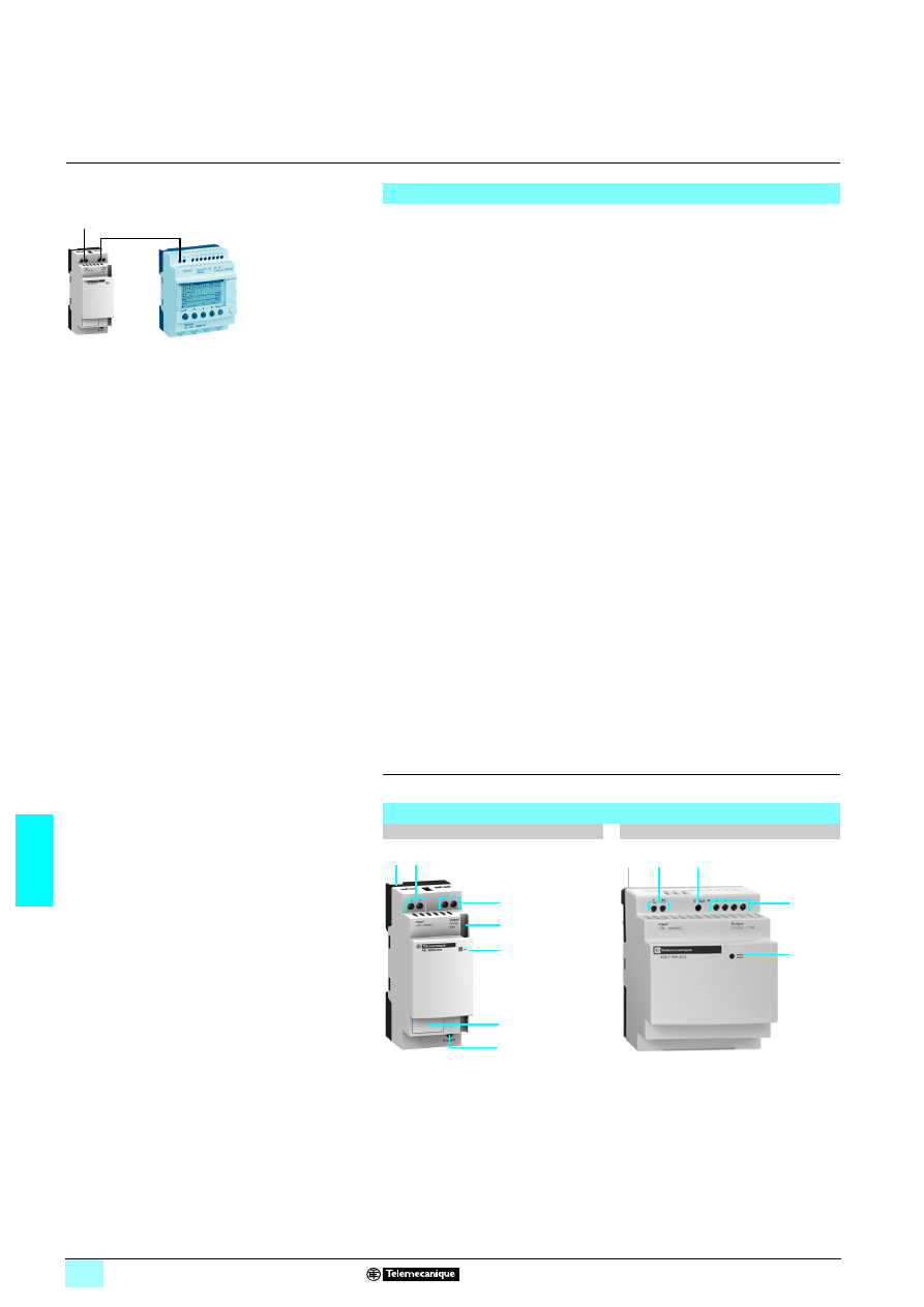
1
2.5 mm
2
screw terminal for connection of the AC input voltage
2
Output voltage adjustment potentiometer
3
2.5 mm
2
screw terminal for connection of the output voltage
4
LED indicating presence of the DC output voltage
5
Duct for throughwiring of the output voltage conductors at the bottom (except for
model ABL 7RM24025)
6
Clip-on marker label (except for model ABL 7RM24025)
7
Retractable fixing lugs for panel mounting
Switch mode power supplies: Modular range
ABL 8MEM
5555522Zelio Logic
1
3
1 ABL8MEM24003
7 W
300 mA
24 V
4
1 ABL8MEM24006
15 W
600 mA
24 V
4
1 ABL8MEM24012
30 W
1.2 A
24 V
4
1 ABL7RM24025
60 W
2.5 A
24 V
4
1 ABL8MEM05040
20 W
4 A
5 V
4
1 ABL8MEM12020
25 W
2 A
12 V
4
Description
ABL 8MEM
5555
ABL7RM24025
3
1
4
5
2
6
7
3
1
4
2
7
7/13
7
Characteristics
7
Power supplies and transformers
7
Power supplies for DC control circuits
Regulated switch mode power supplies
Phaseo Modular range
(1) The certification is not valid for DC input voltages.
Technical characteristics
Power supply type
ABL 8MEM24003
ABL 8MEM24006
ABL 8MEM24012
ABL 7RM24025
Certifications
cULus 508, cCSAus (CSA22.2 n950-1), TUV 60950-1,
6, CTick
Conformity to standards
Safety
IEC/EN 60950-1, SELV
EMC
IEC/EN 61000-6-2, IEC/EN 61000-6-3, IEC/EN 61204-3, EN 55022 Class B
Input circuit
LED indication
No
Input values
Nominal voltage
V
100…240
1
Limit voltage
V
85…264
1
120…250
3 (1)
85…264
1
Current consumption
A
0.25 (100 V
1)
0.18 (240 V
1)
0.4 (100 V
1)
0.25 (240 V
1)
0.65 (100 V
1)
0.4 (240 V
1)
1.2 (120 V
1)
0.7 (240 V
1)
Permissible frequencies
Hz
47…63
Maximum inrush current
A
20
90 for 1 ms
Power factor
> 0.5
Efficiency at nominal load
> 78%
> 80%
> 82%
> 84%
Dissipated power at nominal
load
W
2
3.8
6.6
11.4
Output circuit
LED indication
Green LED
Nominal output values
Voltage (U
Out
)
V
24
3
Current
A
0.3
0.6
1.2
2.5
Power
W
7
15
30
60
Precision
Output voltage
V
Adjustable from 22.8 to 28.8
Line and load regulation
± 3%
Residual ripple - noise
mV
250
200
Holding time
for I max.
U
In =
100 V
1
ms
7 10
U
In =
230 V
1
ms
7 150
Protection
Against short-circuits
Permanent
Against undervoltages
V
–
< 19
Thermal
Yes
–
Operating and environmental characteristics
Connections
Input
mm
2
2 x 0.14…2.5 screw terminals (26…14 AWG)
Output
mm
2
2 x 0.14…2.5 screw terminals
(26…14 AWG)
4 x 0.14…2.5 screw terminals
(26…14 AWG)
Mounting
On
6
rail, 35 x 7.5 mm and 35 x 15 mm or on panel (2 x
∅
4 mm)
Operating position
On vertical plane
Vertical
Connections
Series
Possible, see page 7/15
Parallel
Possible, see page 7/15
Environment
Operating temperature
°C
- 25…+ 70 (derating from 55°C, see page 7/15)
- 25…+ 55
Storage temperature
°C
- 40…+ 70
Relative humidity
90% during operation
95% in storage
Degree of protection
IP 20 conforming to IEC 60529
Vibration acc. to EN 61131-2
3...11.9 Hz amplitude 3.5 mm and 11.9 -150 Hz acceleration 2 g
Protection class according to VDE 0106 1
Class II
Dielectric strength
50 Hz for 1 min
Input/output
V
rms
3000
1
Input fuse incorporated
Yes (not interchangeable)
Emissions
according to EN 61000-6-3
EN 50081-1 (generic)
Radiation
EN 55022 Class B
Conducted on the power line
EN 55022 Class B
Harmonic currents
IEC/EN 61000-3-2
Immunity
according to EN 61000-6-2
IEC 61000-6-2 (generic)
Electrostatic discharge
IEC/EN 61000-4-2 (6 kV contact/8 kV air)
IEC/EN 61000-4-2
(4 kV contact/8 kV air)
Radiated electromagnetic fields
IEC/EN 61000-4-3 level 3
(10 V/m)
Induced electromagnetic fields
IEC/EN 61000-4-6 level 3 (10 V/m)
Rapid transients
IEC/EN 61000-4-4 (4 kV)
Surges
IEC/EN 61000-4-5 (1 kV)
Primary outages
IEC/EN 61000-4-11 (voltage dips and interruptions)
Presentation:
page 7/12
References:
page 7/17
Dimensions:
page 7/17
Schemes:
page 7/17
7/14
7
Characteristics
(continued)
7
Power supplies and transformers
7
Power supplies for DC control circuits
Regulated switch mode power supplies
Phaseo Modular range
(1) The certification is not valid for DC input voltages.
Technical characteristics
Power supply type
ABL 8MEM05040
ABL 8MEM12020
Certifications
cULus 508, cCSAus (CSA22.2 n950-1), TUV EN 60950-1,
6, CTick
Conformity to standards
Safety
IEC/EN 60950-1, SELV
EMC
IEC/EN 61000-6-2, IEC/EN 61000-6-3, IEC/EN 61204-3, EN 55022 Class B
Input circuit
LED indication
No
Input values
Nominal voltage
V
100…240
1
Limit voltage
V
85…264 V
12
120…250 V
32(1)
Current consumption
A
0.55 (100 V
1)
0.35 (240 V
1)
0.6 (100 V
1)
0.35 (240 V
1)
Permissible frequencies
Hz
47…63
Maximum inrush current
A
20
Power factor
> 0.5
Efficiency at nominal load
> 75%
> 80%
Dissipated power at nominal
load
W
6.7
6.2
Output circuit
LED indication
Green LED
Nominal output values
Voltage (U
Out
)
V
5
3
12...15
3
Current
A
4
2.1
Power
W
20
25
Precision
Output voltage
V
Adjustable from 4.75 to 6.25
Adjustable from 11.4 to 15
Line and load regulation
± 3%
Residual ripple - noise
mV
250
Holding time
for I max
U
In
min
ms
7 10
Protection
Against short-circuits
Permanent
Against undervoltages
–
Thermal
–
Operating and environmental characteristics
Connections
Input
mm
2
2 x 0.14…2.5 screw terminals (26…14 AWG)
Output
mm
2
4 x 0.14…2.5 screw terminals (26…14 AWG)
Mounting
On
6
rail, 35 x 7.5 mm and 35 x 15 mm or on panel (2 x
∅
4 mm)
Operating position
On vertical plane
Vertical
Connections
Series
Possible, see page 7/15
Parallel
Possible, see page 7/15
Environment
Operating temperature
°C
- 25…+ 70 (derating from 55°C, see page 7/15)
Storage temperature
°C
- 40…+ 70
Maximum relative humidity
90% during operation
95% in storage
Degree of protection
IP 20 conforming to IEC 60529
Vibration
3...11.9 Hz amplitude 3.5 mm and 11.9 -150 Hz acceleration 2 g
Protection class according to VDE 0106 1
Class II
Dielectric strength
50 Hz for 1 min
Input/output
V
rms
3000
1
Input fuse incorporated
Yes (not interchangeable)
Emissions
according to EN 61000-6-3
EN 50081-1 (generic)
Radiation
EN 55022 Class B
Conducted on the power line
EN 55022 Class B
Harmonic currents
IEC/EN 61000-3-2
Immunity
according to EN 61000-6-2
IEC 61000-6-2 (generic)
Electrostatic discharge
IEC/EN 61000-4-2 (6 kV contact/8 kV air)
Radiated electromagnetic fields
IEC/EN 61000-4-3 level 3
(10 V/m)
Induced electromagnetic fields
IEC/EN 61000-4-6 level 3 (10 V/m)
Rapid transients
IEC/EN 61000-4-4 (4 kV)
Surges
IEC/EN 61000-4-5 (1 kV)
Primary outages
IEC/EN 61000-4-11 (voltage dips and interruptions)
Description:
page 7/12
References:
page 7/17
Dimensions:
page 7/17
Schemes:
page 7/17
7/15
7
Output characteristics
7
Power supplies and transformers
7
Power supplies for DC control circuits
Regulated switch mode power supplies
Phaseo Modular range
Phaseo power supplies are equipped with an electronic protection device.
In the event of an overload or short-circuit, the integrated protection interrupts the
current supply before the output voltage drops below 19 V.
The output voltage reverts to its nominal value on elimination of the fault, which
avoids having to take any action.
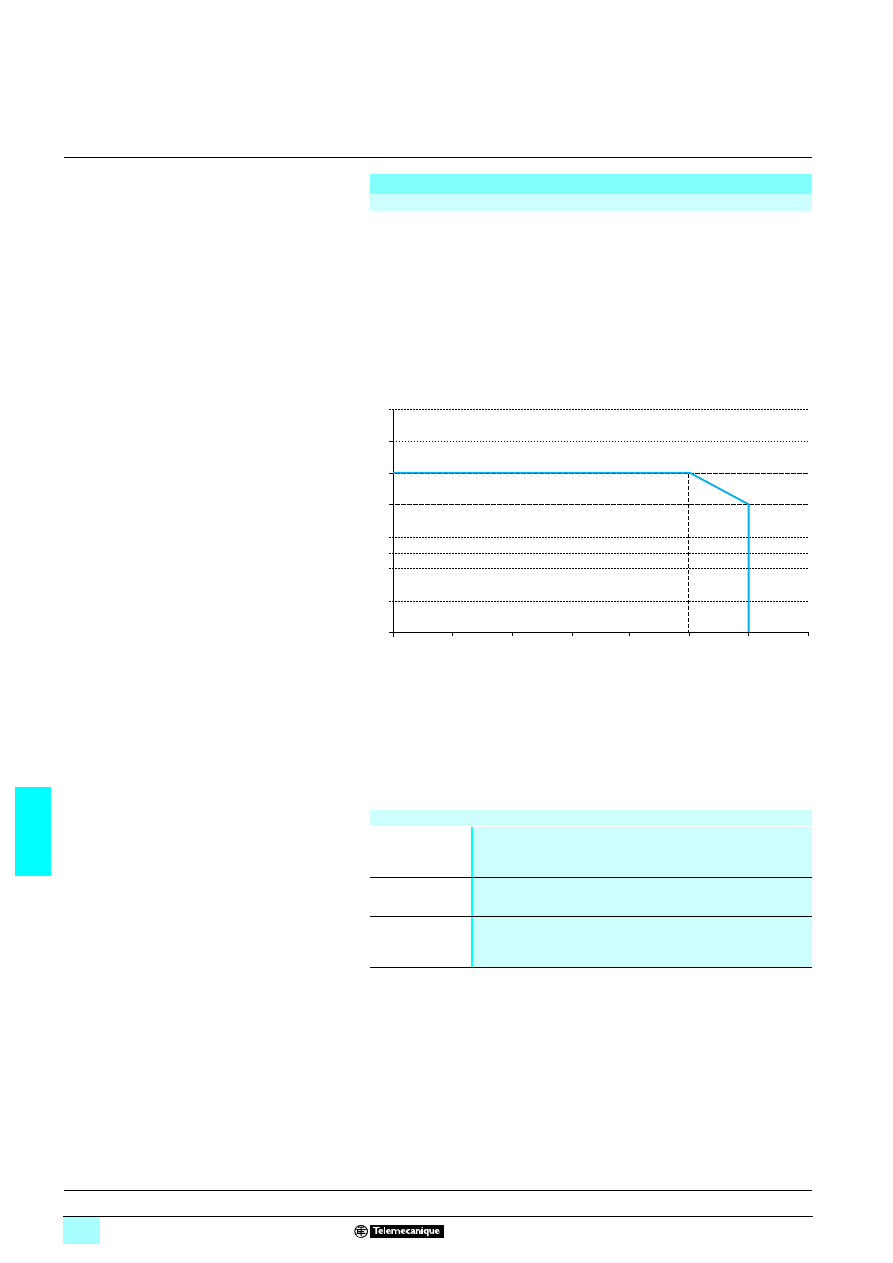
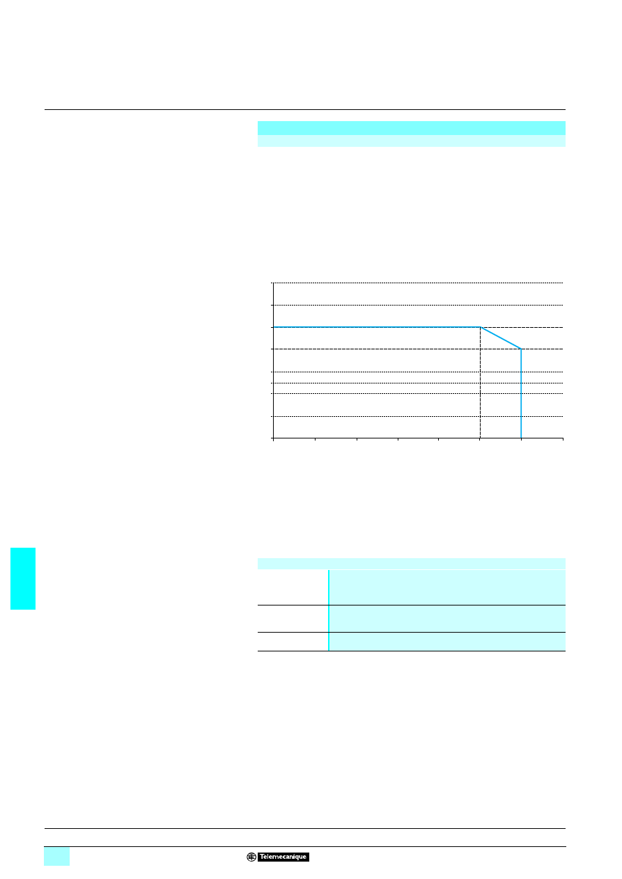
The ambient temperature is a determining factor that limits the power an electronic
power supply can deliver continuously. If the temperature around the electronic
components is too high, their life will be significantly reduced.
The nominal ambient temperature for the Modular range of Phaseo power supplies
is 55°C. Above this temperature, derating is necessary up to a maximum
temperature of 70°C (except for the ABL 7RM24025 model).
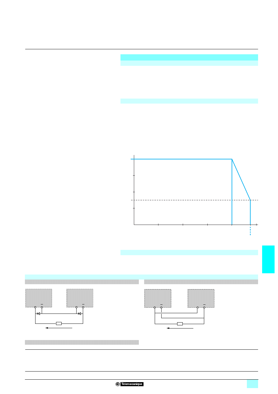
The graph below shows the power as a percentage of the nominal power that the
power supply can deliver continuously, depending on the ambient temperature.
1
With an ABL 7RM24025
2
With an ABL 8MEM
77777
The ABL 8MEM
7777 Modular range of power supplies have an energy reserve that
can be used to supply the application with 125% to 140% of the nominal output
current for a maximum of 1 minute, depending on the model.
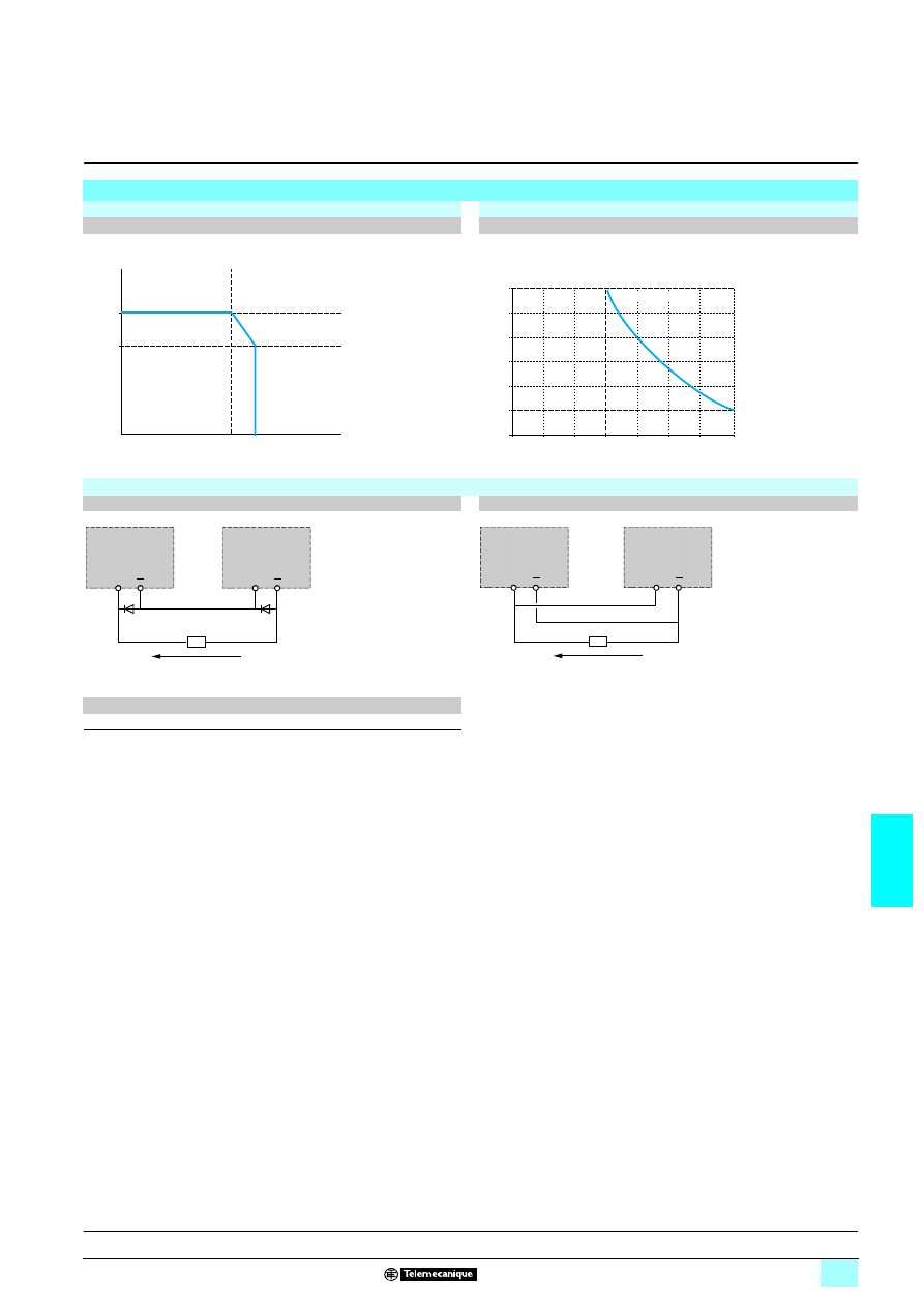
Output characteristics
Behavior in the event of short-circuits and overloads
Derating
100 %
- 25
- 5
15
35
55
75
70
30 %
1
2
P/Pn (%)
Maximum operating temperature (°C)
Temporary overloads
Description:
page 7/12
References:
page 7/17
Dimensions:
page 7/17
Schemes:
page 7/17
Series or parallel connection
Series connection
Parallel connection
(1) Two Shottky diodes Imin = power supply In and Vmin = 50 V
Family
Series
Parallel
ABL 7RM/8MEM
2 products max.
2 products max.
Note: Series or parallel connection is only recommended for products with identical references.
+
+
ABL 7RM
ABL 8MEM
(1)
(1)
ABL 7RM
ABL 8MEM
2 x 24 V
1/I out
+
+
ABL 7RM
ABL 8MEM
ABL 7RM
ABL 8MEM
24 V
1/2 x I out
7/16
7
Combinations,
schemes
7
Power supplies and transformers
7
Power supplies for DC control circuits
Regulated switch mode power supplies
Phaseo Modular range
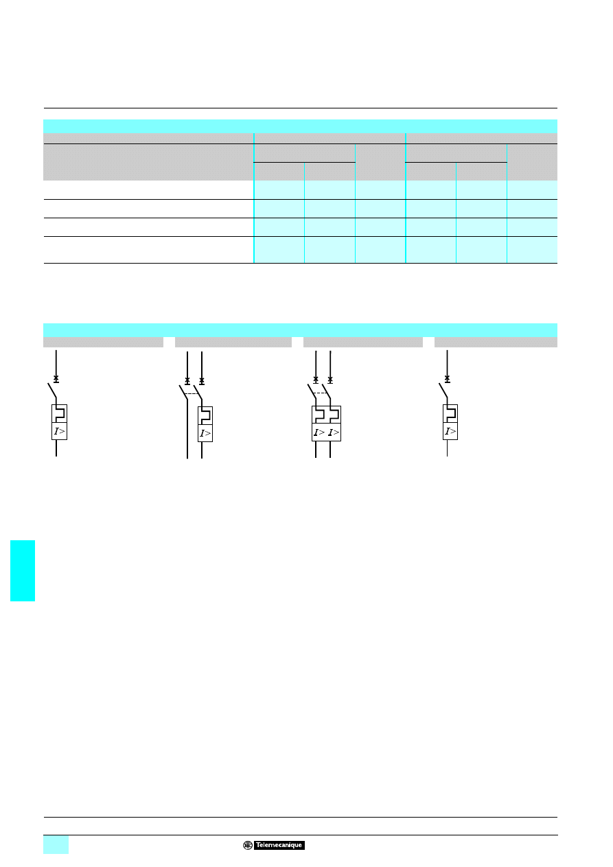
Selection of protection for the power supply primary
Type of line supply
100 to 240 V
2
2
2
2 single-phase
Type of protection
Thermal-magnetic circuit-breaker
gG fuse
GB2 (IEC) (1)
C60N (IEC)
C60N (UL/CSA)
ABL 8MEM05040
GB2
5507 (2)
24581
24517
2 A
ABL 8MEM12020
ABL 8MEM24003
ABL 8MEM24006
ABL 8MEM24012
ABL 7RM24025
GB2
5508 (2)
24582
24518
3 A
(1) UL pending
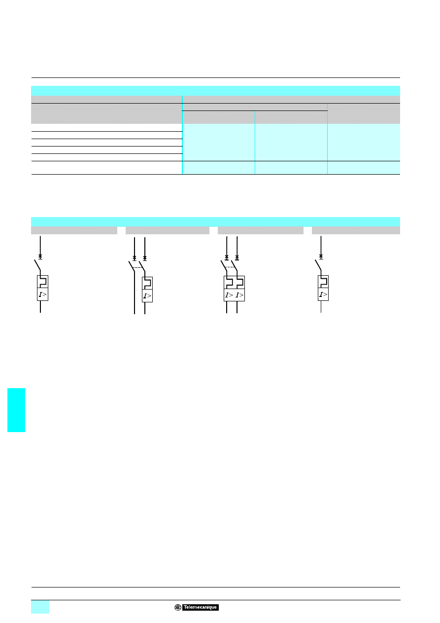
(2) Complete the reference by replacing
55 as required:
- CB for single-pole circuit-breaker with magnetic trip threshold 12 to 16 In
- CD for single-pole + neutral circuit-breaker with magnetic trip threshold 12 to 16 In
- DB for 2-pole circuit-breaker with magnetic trip threshold 12 to 16 In
- CS for single-pole circuit-breaker with magnetic trip threshold 5 to 7 In
Circuit-breaker schemes
GB2 CB
11
11
11
11
GB2 CD
11
11
11
11
GB2 DB
11
11
11
11
GB2 CS
11
11
11
11
2/T1
1/L1
2/T1
4/T2 (14)
1/L1
3/L2 (13)
2/T1
4/T2
1/L1
3/L2
2/T1
1/L1
Description:
page 7/12
Characteristics:
pages 7/13 to 7/15
7/17
7
References,
dimensions,
internal schemes
7
Power supplies and transformers
7
Power supplies for DC control circuits
Regulated switch mode power supplies
Phaseo Modular range
(1) Due to their power < 75 W, the ABL 8MEM/7RM Modular range of power supplies is not
subject to the requirements of standard EN 61000-3-2.
Regulated switch mode power supplies: Phaseo Modular range
Input voltage Secondary
Reset
Conforming
to standard
EN 61000-3-2
(1)
Reference
Weight
kg
Output
voltage
Nominal
power
Nominal
current
Single-phase (N-L1) or 2-phase (L1-L2) connection
100…240 V
-15%, + 10%
50/60 Hz
5 V
3
20 W
4 A
Automatic
Not applicable
ABL 8MEM05040
0.195
12 V
3
25 W
2 A
Automatic
Not applicable
ABL 8MEM05040
0.195
24 V
3
7 W
0.3 A
Automatic
Not applicable
ABL 8MEM24003
0.100
15 W
0.6 A
Automatic
Not applicable
ABL 8MEM24006
0.100
30 W
1.2 A
Automatic
Not applicable
ABL 8MEM24012
0.195
60 W
2.5
Automatic
Not applicable
ABL 7RM24025
0.255
Designation
Use
Sold in packs
of
Unit reference
Weight
kg
Clip-on marker
labels
Replacement parts for ABL 8MEM power supplies
100
LAD 90
0.030
ABL 8MEM05040/12020/24012
ABL 7RM24025
ABL 8MEM24003/24006
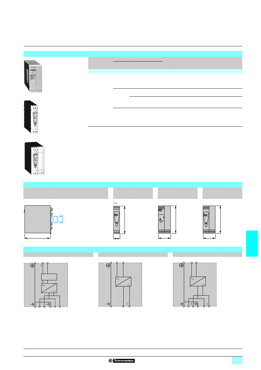
Dimensions
ABL 8MEM
11111
11111
11111
11111/ABL 7RM24025 power supply
a
a1
ABL 8MEM05040
54
42
ABL 8MEM12020
54
42
ABL 8MEM24003
36
24
ABL 8MEM24006
36
24
ABL 8MEM24012
54
42
ABL 7RM24025
72
60
a1
100
90
59
a
44
4
110
Internal schemes
ABL 8MEM2400
5
ABL 8MEM05040/8MEM12020/8MEM24012/7RM24025
–
–
+
+
N
L
–
+
N
L
Description:
page 7/12
Characteristics:
pages 7/13 to 7/15
7/18
7
Presentation,
description
7
Power supplies and transformers
7
Power supplies for DC control circuits
Regulated switch mode power supplies
Phaseo Optimum range
The ABL 8REM/7RP power supply offer is designed to provide the DC voltage
necessary for the control circuits of automation system equipment consuming 60 to
144 W in 12, 24 and 48 V
3
. Comprising four products, this range meets the needs
encountered in industrial, commercial, and residential applications. With
phase-to-neutral (N-L1) or phase-to-phase (1) (L1-L2) connection, these slim
electronic switch mode power supplies provide a quality of output current that is
suitable for the loads supplied and compatible with both the Twido range and the
smallest Modicon M340 configurations, making them ideal partners. Their simplified
characteristics in comparison with the Universal offer also make them the low-cost
solution for applications less affected by problems with the line supply, such as
harmonic pollution and outages. Clear guidelines are given on selecting the
upstream protection devices which are often used with them, and thus a
comprehensive solution is provided that can be used in total safety.
The Optimum range of Phaseo power supplies delivers a voltage that is precise to
3%, whatever the load and whatever the type of line supply, within a range of 85 to
264 V
1
. Conforming to IEC standards and UL, CSA and TUV certified, they are
suitable for universal use. The inclusion of overload and short-circuit protection
makes downstream protection unnecessary if discrimination is not required.
ABL 8REM power supplies do not have an anti-harmonic filter and do not satisfy the
requirements of standard 61000-3-2 concerning harmonic pollution. ABL 7RP power
supplies, however, are equipped with a PFC (Power Factor Correction) filter, thus
ensuring compliance with standard 61000-3-2.
All the Optimum range of Phaseo power supplies have protection devices to ensure
optimum performance of the automation system with an automatic reset mode on
elimination of the fault.
In the event of an overload or short-circuit, the integrated protection interrupts the
current supply before the output voltage drops below 19 V
4. The protection device
resets itself automatically on elimination of the fault, which avoids having to take any
action or change a fuse.
All products are equipped with an output voltage adjustment potentiometer in order
to be able to compensate for any line voltage drops in installations with long cable
runs.
These power supplies are designed for direct mounting on 35 and 75 mm
6
rails.
There are four references available in the Optimum range of Phaseo power supplies:
1
2.5 mm
2
enclosed screw terminals for connection of the input voltage
(single-phase N-L1, phase-to-phase L1-L2 (1))
2
Protective glass flap
3
Input voltage status LED (orange).
4
Output DC voltage status LED (green).
5
Locking catch for the glass flap (sealable)
6
Clip-on marker label.
7
Output voltage adjustment potentiometer
8
2.5 mm
2
enclosed screw terminal block for connection of the DC output voltage
(1) 240 V
3 nominal
Switch mode power supplies: Optimum range
ABL 8REM24030
Twido
1
2
3
4
5
7
8
6
1
3
1 ABL 8REM24030
72 W
3 A
24 V
4
1 ABL 8REM24050
120 W
5 A
24 V
4
1 ABL 7RP1205
60 W
5 A
12 V
4
1 ABL 7RP4803
144 W
3 A
48 V
4
Description
Characteristics:
pages 7/19 to 7/21
References:
page 7/23
Dimensions:
page 7/23
Schemes:
page 7/23
7/19
7
Characteristics
7
Power supplies and transformers
7
Power supplies for DC control circuits
Regulated switch mode power supplies
Phaseo Optimum range
Technical characteristics
Type of power supply
ABL 7RP1205
ABL 7RP4803
ABL 8REM24030
ABL 8REM24050
Certifications
cULus 508, cCSAus (CSA22.2 n950-1), TUV 60950-1,
6, CTick
Conformity to
standards
Safety
IEC/EN 60950, IEC/EN 61496-1-2, SELV
IEC/EN 60950, SELV
EMC
EN 50081-1, IEC 61000-6-2 (EN 50082-2)
Input circuit
LED indication
Orange LED
Input values
Nominal voltage
V
100…240
1
compatible with 110…220
3 (1)
100…240
1
compatible with 110…220
3 (1)
Limit voltage
V
85…264
1
compatible with 100…250
3 (1)
85…264
1 single-phase
compatible with 100…250
3 (1)
Current
consumption
U
In
= 240 V
1
A
0.4
0.6
0.83
1.2
U
In
= 100 V
1
A
0.8
1
1.46
1.9
Permissible frequencies
Hz
47…63
Maximum inrush current
A
30
Power factor
0.98 approx.
0.65 approx.
Efficiency at nominal load
> 85%
Dissipated power at nominal load
W
10.6
25.4
12.7
21.2
Output circuit
LED indication
Green LED
Nominal output values Voltage (U
Out
)
V
12
3
48
3
24
3
Current
A
5
3
3
5
Power
W
60
144
72
120
Precision
Output voltage
V
Adjustable from 24...28.8
3
Line and load regulation
± 3%
Residual ripple - noise
mV
< 200 (peak-peak)
Holding time for I max U
In
= 240 V
1
ms
7 20
7 10
U
In
= 100 V
1
ms
7 20
7 10
Protection
Against short-circuits
Permanent/automatic or manual restart
Permanent/automatic restart
Against overloads
1.1 In
Against overvoltages
Tripping if U
Out
> 1.5 Un
Against undervoltages
Tripping if U
Out
< 0.8 Un
Operating and environmental characteristics
Connections
Input
mm
2
2 x 0.14…2.5 screw terminals (26…14 AWG) + ground
Output
mm
2
2 x 0.14…2.5 screw terminals (26…14 AWG) + ground, multiple output, depending on
model
Mounting
On
6
rail
, 35 x 7.5 mm, 35 x 15 mm and 75 x 7.5 mm
Operating position
On vertical plane
Vertical
Connections
Series
Possible, see page 7/21
Parallel
Possible, see page 7/21
Degree of protection
IP 20 conforming to IEC 60529
Environment
Operating temperature
°C
0… + 60 (derating from 50°C, see page 7/20)
Storage temperature
°C
- 25...+ 70
Maximum relative humidity
95% without condensation or dripping water
Vibration acc. to EN 61131-2
3...11.9 Hz amplitude 3.5 mm and 11.9 -150 Hz acceleration 2 g
Protection class according to VDE 0106 1
Class I
Dielectric strength
50 and 60 Hz for 1 min
Input/output
V rms 3000
Input/ground
V rms 3000
Output/ground (and output/output)
V rms 500
Input fuse incorporated
Yes (not interchangeable)
Emissions
according to EN
61000-6-3
EN 50081-1 (generic)
Conducted/radiated
EN 55011/EN 55022 cl. B
Immunity
according to
EN 61000-6-2
IEC 61000-6-2 (generic)
Electrostatic discharge
IEC/EN 61000-4-2 (6 kV contact/8 kV air)
Radiated electromagnetic fields
IEC/EN 61000-4-3 level 3 (10 V/m)
Induced electromagnetic fields
IEC/EN 61000-4-6 level 3 (10 V/m)
Rapid transients
EN 61000-4-4 level 3 (2 kV)
Surges
IEC/EN 61000-4-5 (2 kV)
Primary outages
IEC/EN 61000-4-11 (voltage dips and interruptions)
(1) The certification is not valid for DC input voltages.
References:
page 7/23
Dimensions:
page 7/23
Schemes:
page 7/23
7/20
7
Output characteristics
7
Power supplies and transformers
7
Power supplies for DC control circuits
Regulated switch mode power supplies
Phaseo Optimum range
The ambient temperature is a determining factor that limits the power an electronic
power supply can deliver continuously. If the temperature around the electronic
components is too high, their life will be significantly reduced.
The nominal ambient temperature for the Optimum range of Phaseo power supplies
is 50 °C. Above this temperature, derating is necessary up to a maximum
temperature of 60 °C.
The graph below shows the power as a percentage of the nominal power that the
power supply can deliver continuously, depending on the ambient temperature.
1
ABL 8REM, ABL 7RP mounted vertically
Derating should be considered in extreme operating conditions:
23Intensive operation (output current permanently close to the nominal current,
combined with a high ambient temperature)
23Output voltage set above 24 V 4 (to compensate for line voltage drops, for
example)
23Parallel connection to increase the total power
In all cases, there must be adequate convection around the products to assist
cooling. There must be sufficient clearance around the Optimum range of Phaseo
power supplies:
2350 mm above and below
2315 mm on the sides
Output characteristics
Derating
0
0
10 20 30 40
50
60
70
20
40
50
60
80
100
120
140
1
P/Pn (%)
Maximum operating temperature (°C)
General rules to be complied with
Intensive operation
See derating on above graph.
Example for ABL 8REM:
- Without derating, from 0°C to 50°C
- Derating of nominal current by 2%, per additional °C, up to 60°C
Rise in output
voltage
The nominal power is fixed.
Increasing the output voltage means that the current delivered must be
reduced.
Parallel connection
to increase the total
power
The total power is equal to the sum of the power supplies used, but the
maximum ambient temperature for operation is 50°C.
To improve heat dissipation, the power supplies must not be in contact
with each other.
Description:
page 7/18
References:
page 7/23
Dimensions:
page 7/23
Schemes:
page 7/23
7/21
7
Output characteristics
(continued)
7
Power supplies and transformers
7
Power supplies for DC control circuits
Regulated switch mode power supplies
Phaseo Optimum range
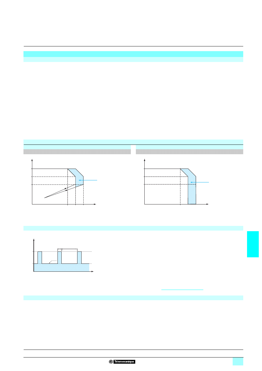
Output characteristics
(continued)
Load limit
Temporary overloads
ABL 8REM240
11
11
11
11/ABL 7RP1111
1111
1111
1111
ABL 8REM/ABL 7RP
Series or parallel connection
Series connection
Parallel connection
1,1 x In
I out
U out
c 19 V
In
c 24 V
1,2
1,3
1,4
1,5
1,6
1,7
1,8
x In
0
10
12
14
16
18
20
T (ms)
I out:(0...100 %)
I out
+
+
ABL 7RM
ABL 8MEM
(1)
(1)
ABL 7RM
ABL 8MEM
2 x 24 V
1/I out
+
+
ABL 7RM
ABL 8MEM
ABL 7RM
ABL 8MEM
24 V
1/2 x I out
Description:
page 7/18
References:
page 7/23
Dimensions:
page 7/23
Schemes:
page 7/23
Family
Series
Parallel
ABL 8REM/7RP
2 products max.
2 products max.
(1) Two Shottky diodes Imin = power supply In and Vmin = 50 V
Note: Series or parallel connection is only recommended for products with identical references.
7/22
7
Combinations,
schemes
7
Power supplies and transformers
7
Power supplies for DC control circuits
Regulated switch mode power supplies
Phaseo Optimum range
Selection of protection for the power supply primary
Type of line supply
100 V
2
2
2
2
240 V
2
2
2
2
Type of protection
Thermal-magnetic
circuit-breaker
gG fuse
Thermal-magnetic
circuit-breaker
gG fuse
GB2 (IEC) (1)
C60N (IEC)
C60N (UL)
GB2 (IEC) (1)
C60N (IEC)
C60N (UL)
ABL 7RP1205
GB2
5506 (2)
24580
24516
2 A
GB2
5506 (2) 24580
24516
1 A
ABL 8REM24030
GB2
5507 (2)
24581
24517
2 A
GB2
5506 (2) 24580
24516
1 A
ABL 8REM24050
GB2
5507 (2)
24581
24517
2 A
GB2
5506 (2) 24580
24516
1 A
ABL 7RP4803
GB2
5507 (2)
24581
24517
2 A
GB2
5506 (2) 24580
24516
1 A
(1) UL pending
(2) Complete the reference by replacing
55 with:
- CB for single-pole circuit-breaker with magnetic trip threshold 12 to 16 In
- CD for single-pole + neutral circuit-breaker with magnetic trip threshold 12 to 16 In
- DB for 2-pole circuit-breaker with magnetic trip threshold 12 to 16 In
- CS for single-pole circuit-breaker with magnetic trip threshold 5 to 7 In
Schemes for GB2
1101 thermal-magnetic circuit-breakers
GB2 CB
11
11
11
11
GB2 CD
11
11
11
11
GB2 DB
11
11
11
11
GB2 CS
11
11
11
11
2/T1
1/L1
2/T1
4/T2 (14)
1/L1
3/L2 (13)
2/T1
4/T2
1/L1
3/L2
2/T1
1/L1
Description:
page 7/18
Characteristics:
pages 7/19 to 7/21
References:
page 7/23
Dimensions:
page 7/23
Schemes:
page 7/23
7/23
7
References,
dimensions,
internal schemes
7
Power supplies and transformers
7
Power supplies for DC control circuits
Regulated switch mode power supplies
Phaseo Optimum range
Regulated switch mode power supplies: Phaseo Optimum range
Input voltage
Secondary
Reset
Conforming
to standard
EN 61000-3-2
Reference
Weight
kg
Output
voltage
Nominal
power
Nominal
current
Single-phase (N-L1) or phase-to-phase (L1-L2) connection
100...240 V
1
- 15%, + 10%
50/60 Hz
12 V
3
60 W
5 A
Automatic or
manual
Yes
ABL 7RP1205
1.000
24 V
3
72 W
3 A
Automatic
No
ABL 8REM24030
0.520
120 W
5 A
Automatic
No
ABL 8REM24050
1.000
48 V
3
144 W
2.5 A
Automatic or
manual
Yes
ABL 7RP4803
1.000
ABL 7RP1205/4803
ABL 8REM24050
ABL 8REM24030
Dimensions
ABL 7RP
5555
Common side view
Mounted on 35 and 75 mm rails
ABL 8REM24030
ABL 7RP1205/4803
ABL 8REM24050
Internal schemes
ABL 7RP1205/48030
ABL 8REM24030
ABL 8REM24050
120
27
120
54
120
54
120
+
–
+
–
L/
+
N/
Filter
+
L
N
+
+
L
N
Description:
page 7/18
Characteristics:
pages 7/19 to 7/21

7/24
7
Presentation
7
Power supplies and transformers
7
Power supplies for DC control circuits
Regulated switch mode power supplies
Phaseo Universal range
The ABL 8RPS/RPM/WPS power supply offer is designed to provide the DC voltage
necessary for the control circuits of automation system equipment. Comprising six
products, this range meets the needs encountered in industrial and commercial
applications. These compact electronic switch mode power supplies provide a
quality of output current that is suitable for the loads supplied and compatible with the
Modicon M340, Premium and Quantum ranges. When used with additional
function modules, they ensure continuity of service in the event of network power
outages or application malfunctions. Clear guidelines are given on selecting the
function modules and upstream protection devices which are often used with them,
and thus a comprehensive solution is provided that can be used in total safety.
The Universal range of Phaseo power supplies must be connected in
phase-to-neutral or phase-to-phase for ABL 8RPS/RPM, and in three-phase for
ABL 8WPS. They deliver a voltage that is precise to 3%, whatever the load and
whatever the type of line supply, within the ranges:
2385 to 132 V
1
and 170 to 550 V
1
for ABL 8RPS
2385 to 132 V
1
and 170 to 264 V
1
for ABL 8RPM
23340 to 550 V
1
for ABL 8WPS
Their very wide input voltage range allows a considerable reduction of parts held in
stock and offers a distinct advantage in terms of machine design.
Conforming to IEC standards and UL and CSA certified, they are suitable for
universal use.
ABL 8RPS/RPM and ABL 8WPS power supplies are all equipped with a harmonic
filter, ensuring compliance with standard 61000-3-2 concerning harmonic pollution.
All the Universal range of Phaseo power supplies have protection devices to ensure
optimum performance of the automation system. Their operating mode can be
configured as required by the user:
1 Manual reset protection mode: Priority is given to the voltage so as to guarantee
the PLC logic states and nominal operation of the supplied actuators.
1 Automatic reset protection mode: Priority is given to the current to allow
troubleshooting for example, or to ensure continuity of service until the arrival of the
maintenance team.
The Universal range of Phaseo power supplies also has a power reserve, allowing
them to deliver a current of 1.5 In at regular intervals. This avoids the need to
oversize the power supply if the device has a high inrush current, while ensuring
optimum performance of the automation system.
The diagnostics for the Universal range of Phaseo power supplies are available on
the front of the device via LEDs (Uout and Iout) and via a volt-free relay contact
(whether or not the PLC states are guaranteed).
All products are equipped with an output voltage adjustment potentiometer in order
to be able to compensate for any line voltage drops in installations with long
connection cable runs.
These power supplies are designed for direct mounting on a 35 mm
6 rail.
Switch mode power supplies: Universal range
ABL 8RPS24050
Modicon M340
automation platform
1
3
Description:
page 7/25
Characteristics:
pages 7/26 to 7/30
References:
page 7/31
Dimensions:
page 7/32
Schemes:
page 7/33
7/25
7
Presentation
(continued)
,
description
7
Power supplies and transformers
7
Power supplies for DC control circuits
Regulated switch mode power supplies
Phaseo Universal range
There are four references available in the Universal range of Phaseo power supplies
for phase-to-neutral or phase-to-phase connection:
The Universal range of Phaseo power supplies also features two references for
three-phase connection:
A range of function modules also allows functions to be added to the Universal range
of Phaseo power supplies so as to ensure continuity of service:
23A Buffer module or Battery check modules combined with their batteries to ensure
continuity of service in the event of a network power outage (see selection tables on
pages 7/38 and 7/39)
23A Redundancy module to meet the most demanding requirements for continuity of
service even if the power supply fails
23Downstream electronic Protection modules to ensure that the protection in the
application is discriminating
23Converter modules delivering nominal voltages of 5 and 12 V 4 from the 24 V 4
output of the Universal range of Phaseo power supplies
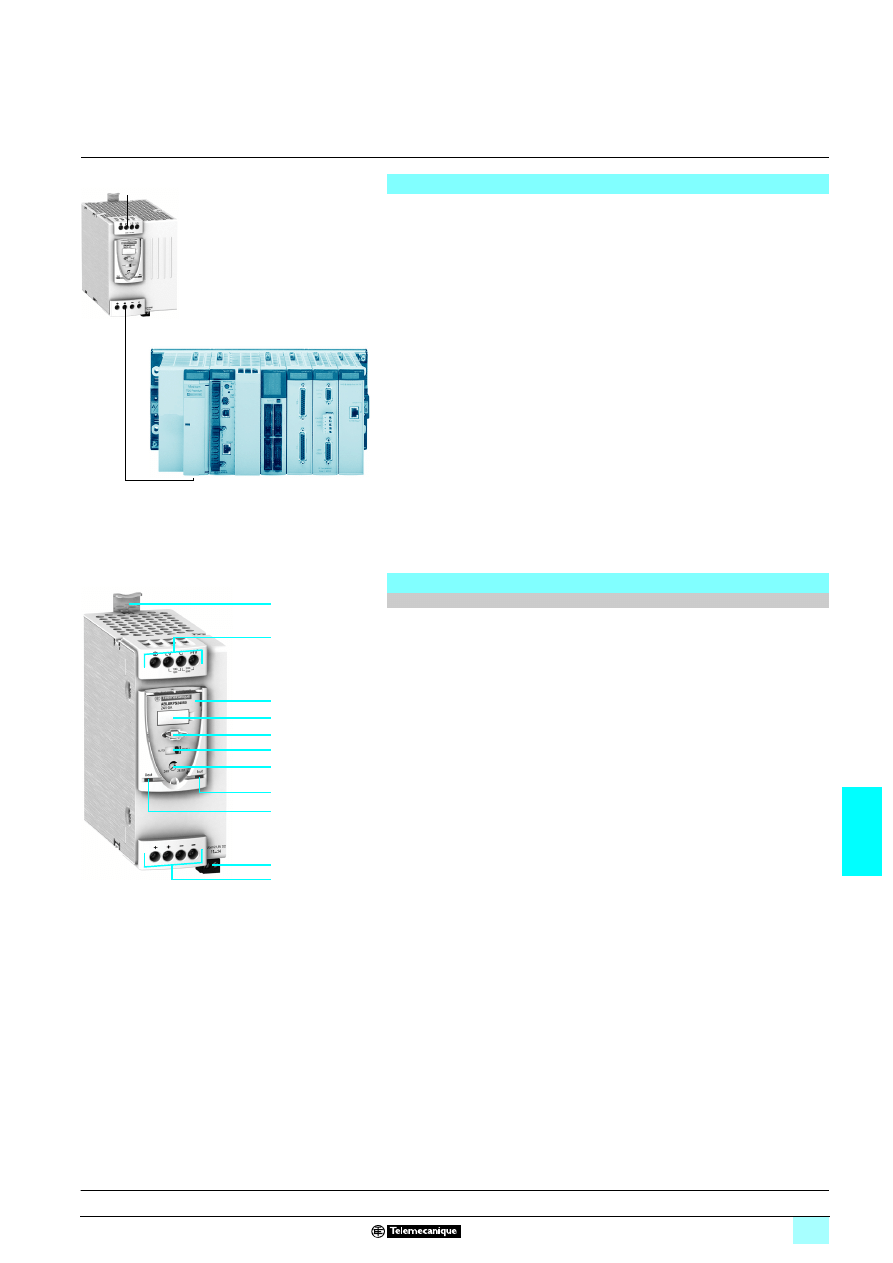
The Universal range of Phaseo regulated switch mode power supplies,
ABL 8RPS24
770/RPM24200/WPS24700, comprise:
1
Spring clip for 35 mm
6 rail
2
4 mm
2
enclosed screw terminals for connection of the AC voltage (single-phase,
phase-to-phase or three-phase connection)
3
Protective glass flap
4
Clip-on marker label
5
Locking catch for the glass flap (sealable)
6
Protection mode selector
7
Output voltage adjustment potentiometer
8
Output voltage status LED (green and red)
9
Output current status LED (green, red and orange)
10
Screw terminals for connection of the diagnostic relay contact, except
ABL 8RPS24030
11
4 mm
2
(10 mm
2
on ABL 8WPS24
700 and ABL 8RPM24200) enclosed screw
terminals for connection of the DC output voltage
Switch mode power supplies: Universal range
(continued)
1 ABL 8RPS24030 72 W
3 A
24
V
4
1 ABL 8RPS24050
120 W
5 A
24 V
4
1 ABL 8RPS24100
240 W
10 A
24 V
4
1 ABL 8RPM24200
480 W
20 A
24 V
4
1 ABL 8WPS24200
480 W
20 A
24 V
4
1 ABL 8WPS24400
960 W
20 A
24 V
4
Description
Universal range of power supplies
ABL 8WPS24200
Premium
automation platform
1
3
11
10
9
8
7
6
4
3
2
5
1
Characteristics:
pages 7/26 to 7/30
References:
page 7/31
Dimensions:
page 7/32
Schemes:
page 7/33
7/26
7
Characteristics
7
Power supplies and transformers
7
Power supplies for DC control circuits
Regulated switch mode power supplies
Phaseo Universal range
(1) No ground screw on ABL 8RPM 24200 power supply
Technical characteristics
Type of power supply
ABL 8RPS24030
ABL 8RPS24050
ABL 8RPS24100
ABL 7RPM24200
Certifications
CB scheme EN 60950-1, UL (pending), cCSAus
Conformity to standards Safety
IEC/EN 60950-1, EN 61204, SELV
EMC
EN 61000-6-1, EN 61000-6-2, EN 61000-6-3, EN 61000-6-4, EN 61204-3
Input circuit
Input values
phase-to-neutral (N-L1) or
phase-to-phase (L1-L2)
Nominal voltage
V
100…120 V
1/200…500 V 1
100…120 V
1 /
200…240 V
1
Limit voltage
V
85…132 V
1/170…550 V 1
85…132 V
1 /
170…264 V
1
Permissible frequencies
Hz
47…63
Maximum inrush current
A
30 for 2 ms max.
Power factor
0.59 at 120 V
1/0.51 at 240 V 1
0.69 at 120 V
1/0.68 at 240 V 1
Efficiency at nominal load
> 87 %
> 88 %
Dissipated power at nominal load
W
7.8
15.5
31
57.6
Anti-harmonic filtering
Yes, via integrated PFC (Power Factor Correction) passive filter
Output circuit
Compatibility with function modules
Buffer, battery and battery check unit, redundancy, discriminating protection
Diagnostics
LEDs on front panel
Current (green, orange and red), voltage (green, red and off)
Relay
–
Relay closed U
Out
> 21.6 V
contact 230 V
1, 0.5 A max; 24 V 3, 5 mA min
Nominal output values
Nominal output voltage (U
Out
)
V
24
3
Current
A
3
5
10
20
Power
W
72
120
240
480
Permissible temporary inrush current (boost)
A
1.5 In for 4 s maximum, see curves on page 7/29
Precision
Nominal output voltage (U
Out
)
V
Adjustable 24…28.8
Line and load regulation
1 %...3 %
Residual ripple - noise
mV
< 200 (peak-peak)
Holding time for I max.
U
In
= 100 V
1
ms
7 20
U
In
= 240 V
1
ms
7 40
U
In
= 400 V
1
ms
7 120
–
Protection
Against short-circuits
Permanent, automatic or manual restart
Against overloads
< 1.10 In (after "boost" function)
Against overvoltages
V
30…32
3
Against undervoltages
V
Tripping if U
Out
< 21.6 (in manual mode)
Thermal
Yes
Operating and environmental characteristics
Connections
Input
mm
2
2 x 0.5….4 screw terminals (22….12 AWG) + ground terminal
Output
mm
2
4 x 0.5….4 screw terminals (22….12 AWG) + ground terminal (1)
Diagnostic relay
mm
2
–
2 x 2.5 removable screw terminal block
Mounting
On
6
rail
35 x 7.5 mm and 35 x 15 mm
Operating position
Vertical
Connections
Series
Possible, see page 7/30
Parallel
Possible, see page 7/30
Degree of protection
IP 20 conforming to IEC 60529
Environment
Operating temperature
°C
- 25…+ 60 (derating from 50°C, see page 7/28)
Storage temperature
°C
- 40…+ 70
Maximum relative humidity
90% during operation, 95% in storage
Vibration acc. to EN 61131-2
3...11.9 Hz amplitude 3.5 mm & 11.9 -150 Hz acceleration 2 g
Protection class According
to
VDE 0106 1
Class I
Dielectric strength
50 Hz for 1 min
Input/output
V rms
4000
1
3000
1
Input/ground
V rms
3500
1
2500
1
Output/ground
V rms
500
1
Input fuse incorporated
No
Emissions
according to EN 61000-6-3
Radiation
EN 55022 Class B and GL levels
Conducted on the power line
EN 55022 Class B and GL levels
Harmonic currents
IEC/EN 61000-3-2
Immunity
according to EN 61000-6-2
and GL
Electrostatic discharge
IEC/EN 61000-4-2 (6 kV contact/8 kV air)
Radiated electromagnetic fields
IEC/EN 61000-4-3 level 3
(10 V/m)
Induced electromagnetic fields
IEC/EN 61000-4-6 level 3 (10 V/m)
Rapid transients
IEC/EN 61000-4-4 (4 kV)
Surges
IEC/EN 61000-4-5 (2 kV)
Primary outages
IEC/EN 61000-4-11 (voltage dips and interruptions)
Description:
page 7/25
References:
page 7/31
Dimensions:
page 7/32
Schemes:
page 7/33
7/27
7
Characteristics
(continued)
7
Power supplies and transformers
7
Power supplies for DC control circuits
Regulated switch mode power supplies
Phaseo Universal range
Technical characteristics
Type of power supply
ABL 8WPS24200
ABL 8WPS24400
Certifications
CB scheme EN 60950-1, UL (pending), cCSAus
Conformity to standards Safety
EN 60950-1, EN 61204, SELV
EMC
EN 61000-6-1, EN 61000-6-2, EN 61000-6-3, EN 61000-6-4, EN 61204-3
Input circuit
LED indication
–
Input values
3 phases (L1-L2-L3)
Nominal values
V
380-500 V
1
Permissible values
V
320-550 V
1
Permissible frequencies
Hz
47…63
Maximum inrush current
A
25 for 2 ms max.
Power factor
0.65
0.85
Efficiency at nominal load
> 92%
Dissipated power at nominal load
W
38.4
76.8
Anti-harmonic filtering
Yes, via integrated PFC (Power Factor Correction) passive filter
Operating mode in the event of phase failure
V
Operation possible for a few minutes then protection trips
Output circuit
Compatibility with function modules
Buffer, battery and battery check unit, redundancy, discriminating protection
Diagnostics
LEDs on front panel
Current (green, orange and red), voltage (green, red and off)
Relay
Closed relay U
out
> 21.6 V, contact 230 V
21, 0.5 A max; 24 V 3, 5 mA min
Nominal output values
Output voltage (U
Out
)
V
24
3
Current
A
0...20
0...40
Power
W
480
960
Permissible temporary inrush current (boost)
A
1.5 In for 4 s maximum, see curves on page 7/29
Precision
Output voltage (U
Out
)
V
Adjustable 24…28.8
Line and load regulation
1 %...3 %
Residual ripple - noise
mV
< 200 (peak-peak)
Holding time
for I max
U
In
= 400 V
1
ms
7 18
7 14
Protection
Against short-circuits
Permanent, automatic or manual restart
Against overloads
< 1.10 In (after "boost" function)
Against overvoltages
V
30…32
3
Against undervoltages
V
Tripping if U
Out
< 21.6 (in manual mode)
Thermal
Yes
Operating and environmental characteristics
Connections
Input
mm
2
3 x 0.5….4 screw terminals (22….12 AWG) + ground
Output
mm
2
4 x 0.5….10 screw terminals (22….8 AWG)
Diagnostic relay
mm
2
2 x 2.5 removable screw terminal block
Mounting
On
6
rail
35 x 7.5 mm and 35 x 15 mm
Operating position
Vertical
Connections
Series
Possible, see page 7/30
Parallel
Possible, see page 7/30
Degree of protection
IP 20 conforming to IEC 60529
Environment
Operating temperature
°C
- 25…+ 60 (derating from 50°C, see page 7/28)
Storage temperature
°C
- 40…+ 70
Maximum relative humidity
90% during operation, 95% in storage
Vibration acc. to EN 61131-2
3...11.9 Hz amplitude 3.5 mm & 11.9 -150 Hz acceleration 2 g
Protection class according to VDE 0106 1
Class I
Dielectric strength
50 Hz for 1 min
Input/output
V rms
4000
1
Input/ground
V rms
3500
1
Output/ground
V rms
500
1
Input fuse incorporated
No
Emissions
according to EN 61000-6-3
Radiation
EN 55022 Class B and GL levels
Conducted on the power line
EN 55022 Class B and GL levels
Harmonic currents
IEC/EN 61000-3-2
Immunity
according to EN 61000-6-2
and GL
Electrostatic discharge
IEC/EN 61000-4-2 (6 kV contact/8 kV air)
Radiated electromagnetic fields
IEC/EN 61000-4-3 level 3
(10 V/m)
Induced electromagnetic fields
IEC/EN 61000-4-6 level 3 (10 V/m)
Rapid transients
IEC/EN 61000-4-4 (4 kV)
Surges
IEC/EN 61000-4-5 (1 kV)
Primary outages
IEC/EN 61000-4-11 (voltage dips and interruptions)
Description:
page 7/25
References:
page 7/31
Dimensions:
page 7/32
Schemes:
page 7/33
7/28
7
Output characteristics
7
Power supplies and transformers
7
Power supplies for DC control circuits
Regulated switch mode power supplies
Phaseo Universal range
The ambient temperature is a determining factor that limits the power an electronic
power supply can deliver continuously. If the temperature around the electronic
components is too high, their life will be significantly reduced.
The nominal ambient temperature for the Universal range of Phaseo power supplies
is 50°C. Above this temperature, derating is necessary up to a maximum
temperature of 60°C.
The graph below shows the power (in relation to the nominal power) that the power
supply can deliver continuously, depending on the ambient temperature.
ABL 8RPM, ABL 8RPS, ABL 8WPS mounted vertically
Derating should be considered in extreme operating conditions:
23Intensive operation (output current permanently close to the nominal current,
combined with a high ambient temperature)
23Output voltage set above 24V (to compensate for line voltage drops, for example)
23Parallel connection to increase the total power
In all cases, there must be adequate convection around the products to assist
cooling. There must be sufficient clearance around the Universal range of Phaseo
power supplies:
2350 mm above and below
2310 mm on the sides
Output characteristics
Derating
0
0
10
20
30
40
50
60
70
20
40
50
60
80
100
120
140
P/Pn (%)
Maximum operating temperature (°C)
General rules to be complied with
Intensive operation
See derating on above graph.
Example for ABL 8RPS:
- Without derating, from 0°C to 50°C
- Derating of nominal current by 2%, per additional °C, up to 60°C
Rise in output
voltage
The nominal power is fixed.
Increasing the output voltage means that the current delivered must be
reduced.
Mounting
To allow heat dissipation, the power supplies must not be in contact with
each other.
Description:
page 7/25
References:
page 7/31
Dimensions:
page 7/32
Schemes:
page 7/33
7/29
7
Output characteristics
(continued)
7
Power supplies and transformers
7
Power supplies for DC control circuits
Regulated switch mode power supplies
Phaseo Universal range
Behavior in the event of overloads:
1 Automatic reset protection mode (current limiting): If the output current
exceeds approximately 1.2 In, the output current is limited to this value. The value of
the output voltage can then be less than 21 V but the diagnostic relay opens, allowing
the anomaly to be fed back to the automation system and thus prevent feedback of
any undefined logic state. On elimination of the overload, the output voltage reverts
to its preset value.
1 Manual reset protection mode (undervoltage detection): If the output current
exceeds approximately 1.2 In, the power supply stops completely before the output
voltage drops below 21 V and no longer delivers any current. The fault is memorized
as long as voltage is present at the power supply primary. The power supply will
become operational again, if the fault has disappeared, after de-energizing the
primary for a few seconds.
Note: In both these modes, any overload of less than 1.5 In and lasting less than 4 s will be
absorbed by the "boost" circuit and the voltage delivered will stay within the specified limits
(adjustment voltage +/- 3%).
The ABL 8RPS/RPM/WPS Universal range of Phaseo power supplies has a power
reserve, allowing them to supply the application with energy up to 1.5 times the
nominal current at the intervals illustrated by the graph opposite.
The "boost" amplitude and repeat accuracy depend on:
23The overload duration
23The overload intensity
23The period between each consumption peak
When the power supply can no longer cope (repeated overloads, overload duration
> 4 seconds, power rating > 150% of nominal power) the integrated protection trips.
This type of operation is described in detail in the user manual, which can be
downloaded from our website,
www.telemecanique.com
.
The ABL 8WPS24
700 Universal range of Phaseo power supplies is capable of
starting and delivering a nominal current and voltage for a few minutes in the event
of failure of one phase. Their protection (thermal) then trips and they are reset
automatically.
Output characteristics (continued)
Behavior in the event of overloads
Load limit
Manual reset protection mode
Automatic reset protection mode
ABL 8RPM24200/ABL 8RPS24
111
111
111
111
/ABL 8WPS24
111
111
111
111
ABL 8RPM24200/ABL 8RPS24
111
111
111
111
/ABL 8WPS24
111
111
111
111
U out
I out
28,8
24
21,6
In
1,5 In
1,2 In
Boost 4 s
U out
I out
28,8
24
21,6
In
1,5 In
1,2 In
Boost 4 s
"Boost" repeat accuracy
150 %
75 %
0 %
30 s
30 s
4 s
t
Pout
Behavior in the event of phase failure on three-phase power supplies
Description:
page 7/25
References:
page 7/31
Dimensions:
page 7/32
Schemes:
page 7/33
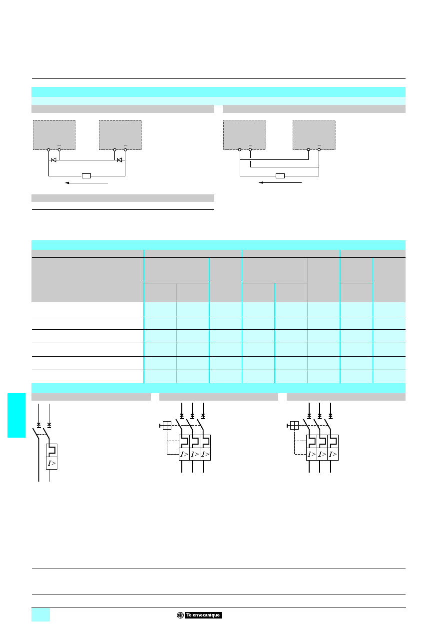
7/30
7
Output characteristics
(continued)
,
selection,
schemes
7
Power supplies and transformers
7
Power supplies for DC control circuits
Regulated switch mode power supplies
Phaseo Universal range
Output characteristics (continued)
Series or parallel connection
Series connection
Parallel connection
Family
Series
Parallel
ABL 8RPS/8RPM/8WPS
2 products max. (1)
2 products max.
Note: Series or parallel connection is only recommended for products with identical references.
For better availability, the power supplies can also be connected in parallel using the ABL8 RED24400 Redundancy module.
Selection of protection on the power supply primaries
Type of line supply
115 V
2
2
2
2 phase-to-neutral
230 V
2
2
2
2 phase-to-phase
400 V
2
2
2
2 phase-to-phase
Type of protection
Thermal-magnetic
circuit-breaker
gG/gL
fuse
Thermal-magnetic
circuit-breaker
gG/gL
fuse
Thermal-
magnetic
circuit-
breaker
gG/gL
fuse
Telemecanique
GB2 (IEC)
(2)
Merlin Gerin
C60N (IEC)
C60N (UL)
Telemecanique
GB2 (IEC)
(2)
Merlin Gerin
C60N (IEC)
C60N (UL)
Telemecanique
GV2
(IEC/UL)
ABL 8RPS24030
GB2 CD07
MG24443
2 A
(8 x 32)
GB2 CD07
MG24443
2 A
(8 x 32)
GV2 RT06
2 A
(14 x 51)
ABL 8RPS24050
GB2 CD08
MG24444
4 A
(8 x 32)
GB2 CD07
MG24443
2 A
(8 x 32)
GV2 RT06
2 A
(14 x 51)
ABL 8RPS24100
GB2 CD12
MG24447
6 A
(8 x 32)
GB2 CD08
MG24444
4 A
(8 x 32)
GV2 RT07
4 A
(14 x 51)
ABL 8RPM24200
GB2 CD16
MG24449
10 A
(8 x 32)
GB2 CD12
MG24447
6 A
(8 x 32)
–
–
ABL 8WPS24200
–
–
–
–
–
–
GV2 ME07
2 A
(14 x 51)
ABL 8WPS24400
–
–
–
–
–
–
GV2 ME08
4 A
(14 x 51)
Schemes
GB2 CD
11
11
11
11
GV2 RT
11
11
11
11
GV2 ME
11
11
11
11
(1) Two Shottky diodes Imin = power supply In and Vmin = 50 V
(2) UL certification pending
+
+
ABL 8RP
ABL 8WP
(1)
(1)
ABL 8RP
ABL 8WP
2 x 24 V
1/I out
+
+
ABL 8RP
ABL 8WP
ABL 8RP
ABL 8WP
24 V
1/2 x I out
2/T1
4/T2 (14)
1/L1
3/L2 (13)
2/T1
4/T2
6/T3
1/L1
3/L2
5/L3
2/T1
4/T2
6/T3
1/L1
3/L2
5/L3
Description:
page 7/25
References:
page 7/31
Dimensions:
page 7/32
Schemes:
page 7/33
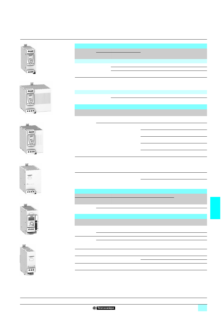
7/31
7
References
7
Power supplies and transformers
7
Power supplies for DC control circuits
Regulated switch mode power supplies
Phaseo Universal range
Regulated switch mode power supplies: Phaseo Universal range
Input
voltage
Secondary
Reset
Conforming
to standard
EN 61000-3-2
Reference
Weight
kg
Output
voltage
Nominal
power
Nominal
current
Single-phase (N-L1) or 2-phase (L1-L2) connection
100…120 V -
200...500 V
23
23
23
23
- 15%,+ 10%
50/60 Hz
24...28.8 V
3
72 W
3 A
Auto/man
Yes
ABL 8RPS24030
0.300
120 W
5 A
Auto/man
Yes
ABL 8RPS24050
0.700
240 W
10 A
Auto/man
Yes
ABL 8RPS24100
1.000
100…120 V/200..
.240 V
23
23
23
23
- 15%,+ 10%
50/60 Hz
24...28.8 V
3
480 W
20 A
Auto/man
Yes
ABL 8RPM24200
1.600
Three-phase connection (L1-L2-L3)
380…500 V
2
2
2
2
± 10 %
50/60 Hz
24...28.8 V
3
480 W
20 A
Auto/man
Yes
ABL 8WPS24200 1.600
960 W
40 A
Auto/man
Yes
ABL 8WPS24400 2.700
Function modules for continuity of service
Function
Use
Designation
Reference
Weight
kg
Continuity after
a power outage
Holding time 100 ms at 40 A and 2 s at
1 A
Buffer module
ABL 8BUF24400
1.200
Holding time 9 min at 40 A...2 hrs at
1 A (depending on use with a battery
check module-battery unit and load)
(1)
Battery check module
20 A output current
ABL 8BBU24200
4
4
4
4
0.500
Battery check module
40 A output current
ABL 8BBU24200
4
4
4
4
0.700
3.2 Ah battery module (2)
ABL 8BPK24A03
4
4
4
4
3.500
7 Ah battery module (2)
ABL 8BPK24A03
4
4
4
4
6.500
12 Ah battery module (2)
ABL 8BPK24A12
4
4
4
4
12.000
Continuity after
a malfunction
Paralleling and redundancy of the
power supply to ensure uninterrupted
operation of the application excluding
AC line failures and application
overloads
Redundancy module
ABL 8RED24400
0.700
Discriminating
downstream
protection
Electronic protection (1...10 A
overload or short-circuit) with 4 output
terminals from a Universal range
Phaseo power supply
Protection module with
single-pole breaking (3)
ABL 8PRE24100
4
4
4
4
0.270
Protection module with
2-pole breaking (4) (3)
ABL 8PRP24100
4
4
4
4
0.270
2/2 converters
(for use with Universal range of Phaseo power supplies)
Primary (5)
Secondary
Reference
Weight
kg
Input voltage
Universal range power supply
module output current
Output
voltage
Nominal
current
24 V
5
5
5
5
- 9%, + 24%
2.2 A
5...6.5 V
3 6 A
ABL 8DCC05060
0.300
1.7 A
7...15 V
3
2 A
ABL 8DCC12020
0.300
Separate and replacement parts
Designation
Description
Composition
Unit reference
Weight
kg
Fuse
assemblies
For ABL 8PR
524100 discriminating
Protection modules
4 x 3 A, 4 x 7.5 A and 4 x
15 A
ABL 8FUS01
–
For ABL 8BKP24A
55 Battery
4 x 20 A and 6 x 30 A
ABL 8FUS02
–
Clip-on marker
labels
All products except ABL 8PR
555555
Order in multiples of 100
LAD 90
0.030
ABL 8PR
555555
Order in multiples of 22
ASI20MACC5
–
DIN rail
mounting kit
For ABL 8BPK2403 Battery Module
Single unit
ABL 1A02
–
Cables
Connection cable between ABL8 BBU
and PC for updating the software
RS232 3 m
SR2CBL01
0.150
USB 3 m
SR2USB01
0.150
EEPROM
memory
Backup and duplication of ABL8 BBU
parameters
Single unit
SR2MEM02
0.010
(1) For table of compatibility of battery check module-battery unit with holding time depending on the load,
see page 7/39.
(2) Supplied with 20 or 30 A fuse depending on the model.
(3) Supplied with four 15 A fuses.
(4) Local reset via pushbutton or automatic reset on elimination of the fault and diagnostic relay.
(5) Voltage from a 24 V
1 Universal range Phaseo power supply.
8 Available 2
nd
quarter 2007.
ABL 8RPS24050
ABL 8RPM24200
ABL 8WPS24200
ABL 8BUF24400
ABL 8BBU24200
ABL 8RED24400
Description:
page 7/25
Characteristics:
pages 7/26 to 7/30
Dimensions:
page 7/32
Schemes:
page 7/33
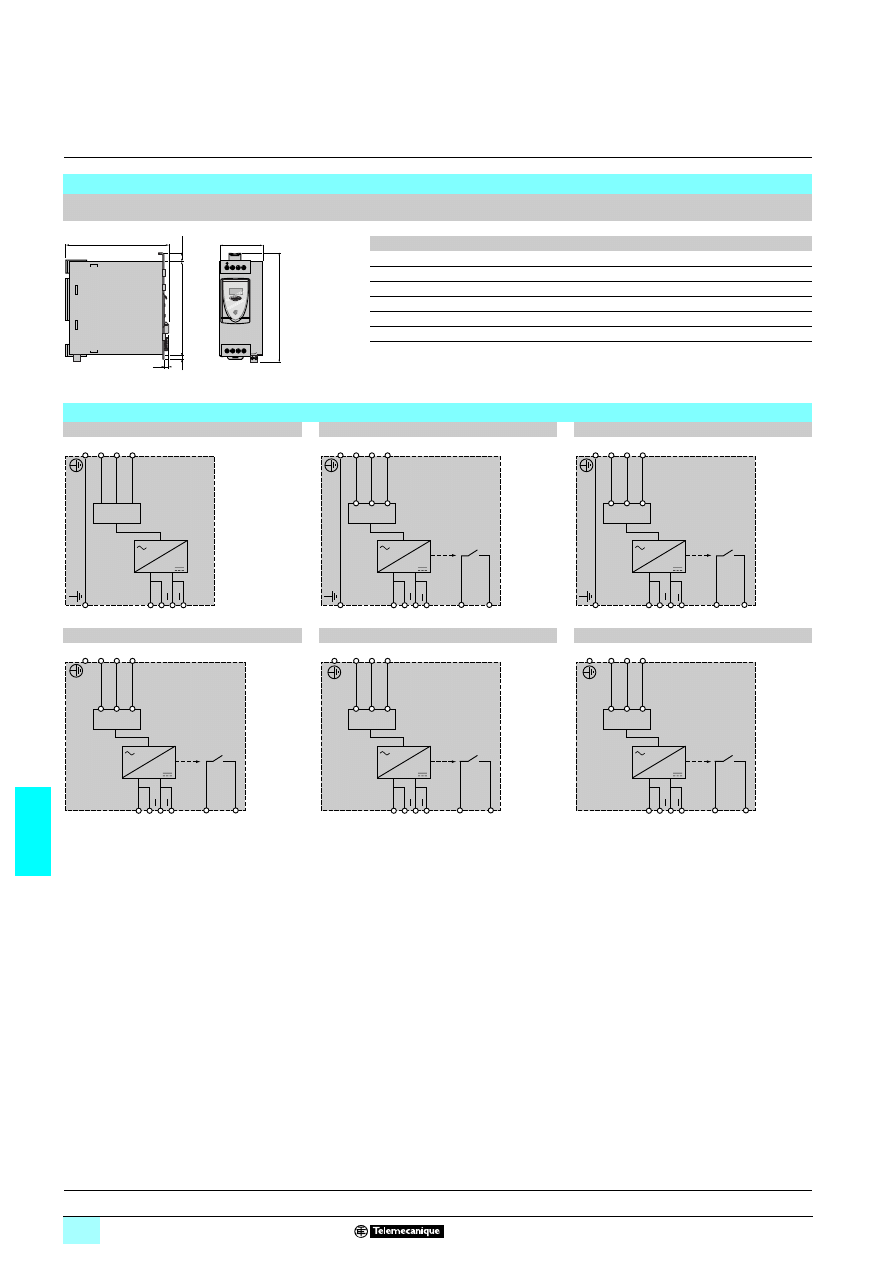
7/32
7
Dimensions,
internal schemes
7
Power supplies and transformers
7
Power supplies for DC control circuits
Regulated switch mode power supplies
Phaseo Universal range
Dimensions
ABL 8RPS24
555/ABL 8RPM24200/ABL 8WPS24555
Common side view
ABL 8
a
b
RPS24030
120
44
RPS24050
120
56
RPS24100
140
85
RPM24200
140
145
WPS24200
155
95
WPS24400
155
165
12
a
b
+
IN
OUT
+
125
6
6
143
L1 N/L2 L3
11
14
Description:
page 7/25
Characteristics:
pages 7/26 to 7/30
References:
page 7/31
Schemes:
page 7/33
Internal schemes
ABL 8RPS24030
ABL 8RPS24050
ABL 8RPS24100
ABL 8RPM24200
ABL 8WPS24200
ABL 8WPS24400
+
HV
C
+
LV
PFC
+
HV
C
+
LV
PFC
11
14
+
HV
C
+
LV
PFC
11
14
+
HV
C
+
LV
PFC
11
14
+
L3
L2
+
L1
PFC
11
14
+
L3
L2
+
L1
PFC
11
14
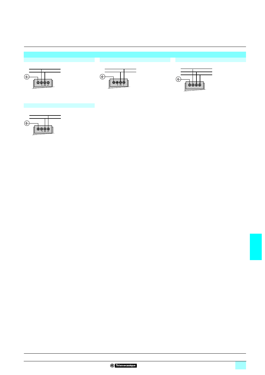
7/33
7
Connections
7
Power supplies and transformers
7
Power supplies for DC control circuits
Regulated switch mode power supplies
Phaseo Universal range
Line supply connection schemes
Single-phase (L-N) 100 to 120 V
Phase-to-phase (L1-L2) 200 to 500 V
Three-phase (L1-L2-L3) 3 x 380 to 500 V
Single-phase (L-N) 200 to 500 V
L
N
LV C HV
100
120
200
500
Ph 1
Ph 2
LV
C HV
100
120
200
500
L 1
L 2
L 3
L1 L2 L3
3x380 - 500 VAC
L
N
LV C HV
100
120
200
500
Description:
page 7/25
Characteristics:
pages 7/26 to 7/30
References:
page 7/31
Dimensions:
page 7/32
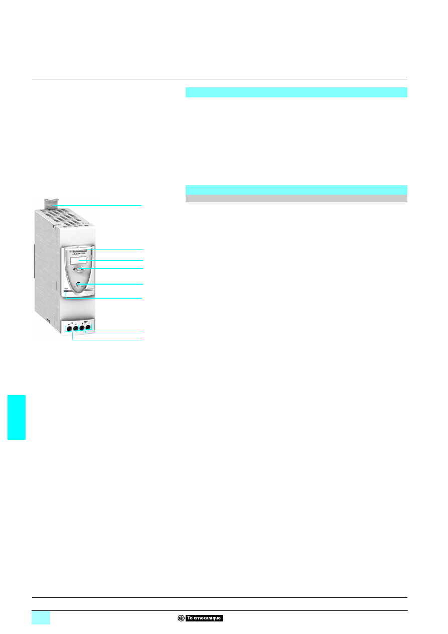
7/34
7
Presentation,
description
7
Power supplies and transformers
7
Regulated switch mode power supplies
Phaseo Universal range: Converter modules
The Phaseo range offers modules that convert the 24 V
3
voltage to a 5 to 15 V
3
voltage.
These modules can be used to make savings in the:
23Upstream protection normally used with the 5 to 15 V
3
power supply
23Connection to the line supply
There are two references available for this solution:
1 ABL 8DCC05060 : 5...6.5 V
3
, 6 A converter module
1 ABL 8DCC12020 : 7...15 V
3
, 2 A converter module
The ABL 8DCC
77070 4/4 Converter modules comprise:
1
Spring clip for 35 mm
6 rail
2
Protective glass flap
3
Clip-on marker label
4
Locking catch for the glass flap (sealable)
5
Output voltage adjustment potentiometer
6
Output current status LED (green)
7
4 mm
2
enclosed screw terminals for connection of the 24 V
4 input voltage
8
4 mm
2
enclosed screw terminals for connection of the 5 V
4 or 12 V 4 output
voltage
Supplying 5 V
2 and 12 V 2 auxiliary voltages
Description
5 V
5
5
5
5 and 12 V 5
5
5
5 Converter modules
1
8
6
5
3
2
4
7
Characteristics:
page 7/35
References:
page 7/36
Dimensions:
page 7/37
Schemes:
page 7/37
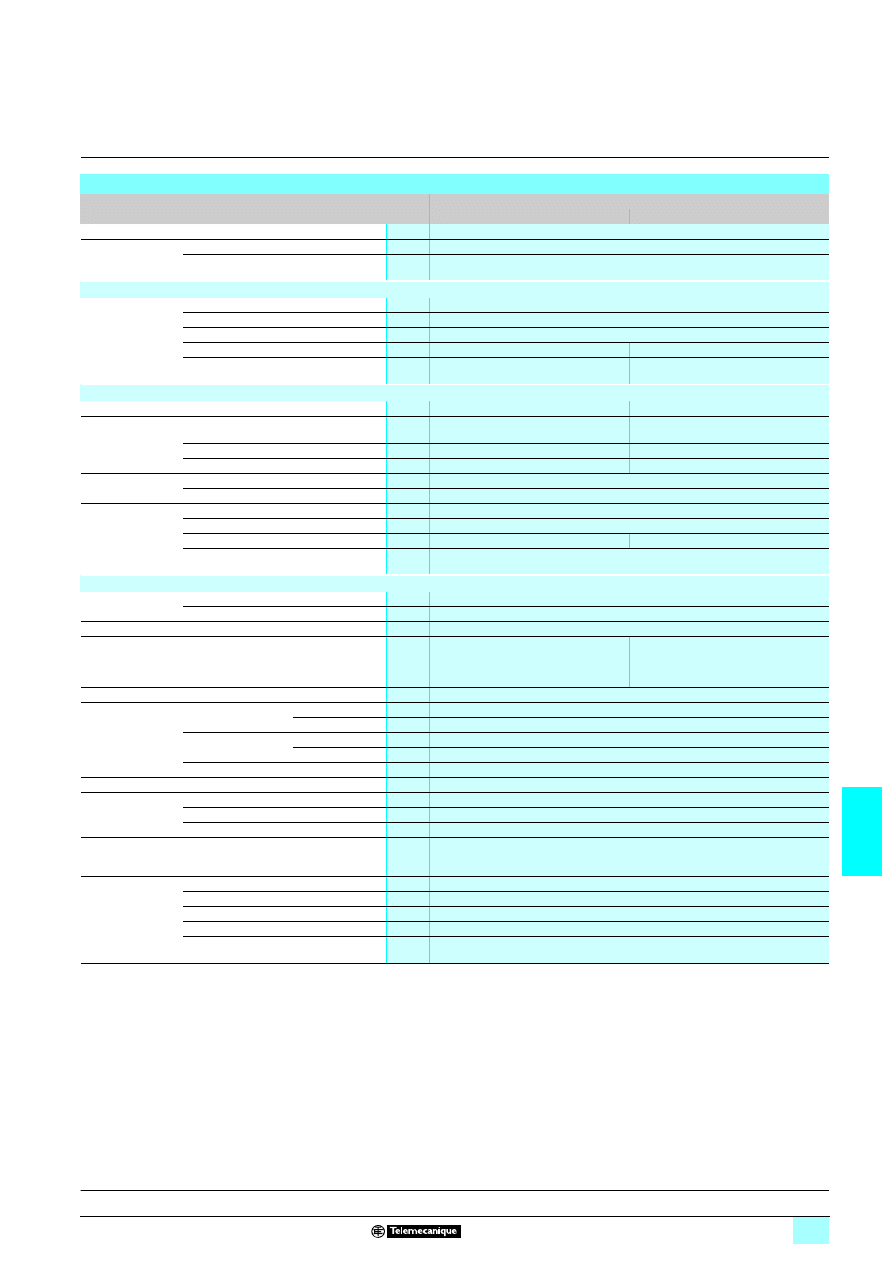
7/35
7
Characteristics
7
Power supplies and transformers
7
Regulated switch mode power supplies
Phaseo Universal range: Converter modules
Technical characteristics
Type of module
Converter
ABL 8DCC05060
ABL 8DCC12020
Certifications
CB scheme EN60950-1, UL (pending), cCSAus
Conformity to
standards
Safety
EN60950-1, EN61204
EMC
EN 50081-1, EN61000-6-2, EN61000-6-3
Input circuit
Input values
Nominal voltage
V
24...28.8
3
Limit voltage
V
22...30
3
Protection against reverse polarity
Yes
Efficiency at nominal load
> 80%
> 82%
Dissipated power at nominal load
W
7
4
Output circuit
Diagnostics
LEDs on front panel
Voltage > 4 V
3 (green)
Voltage > 6 V
3 (green)
Nominal output
values
Output voltage (U
Out
)
V
5
3
Adjustable from 5...6.5
3
12
3
Adjustable from 7...15
3
Current
A
6
2
Power
W
30
24
Precision
Line and load regulation
1...3%
Residual ripple - noise
mV
< 100
Protection
Against short-circuits
Permanent, automatic restart
Against overloads
Permanent, automatic restart I
Out
> 1.1 In
Against overvoltages
V
Permanent, automatic restart U
Out
> 7.8
Permanent, automatic restart U
Out
> 18
Thermal
–
Operating and environmental characteristics
Connections
Input
mm
2
2 x 0.5...4 (24...10 AWG)
Output
mm
2
2 x 0.5...4 (24...10 AWG)
Mounting
On
4 rail
35 x 7.5 mm and 35 x 15 mm
Operating position Vertical plane
Mounted vertically
Mounted horizontally with derating of
power from 50 °C to 60 °C
(40% maximum to 60°C)
Vertical or horizontal position
Degree of protection
IP 20 conforming to IEC 60529
Environment
Temperature
Operation
°C
- 40…+ 85
Storage
°C
- 25…+ 60
Relative humidity
Operation
90%
Storage
95%
Vibration acc. to EN 61131-2
3...11.9 Hz amplitude 3.5 mm; 11.9... 150 Hz acceleration 2 g
Protection class
Class III
Dielectric strength
50 Hz for 1 min
Input/output
V rms
500
1
Input/ground
V rms
500
1
Output/ground
V rms
500
1
Emissions
according to EN
61000-6-3
Conducted/radiated
EN 55022 - Class B
Immunity
according to
EN 61000-6-2
Electrostatic discharge
IEC/EN 61000-4-2 (6 kV contact/8 kV air)
Radiated electromagnetic fields
IEC/EN 61000-4-3 level 3 (10 V/m)
Induced electromagnetic fields
IEC/EN 61000-4-6 level 3 (10 V/m)
Rapid transients
IEC/EN 61000-4-4 level 3 (2 kV)
Surges
IEC/EN 61000-4-5 level 2 (1 kV)
Presentation:
page 7/34
Description:
page 7/34
References:
page 7/36
Dimensions:
page 7/37
Schemes:
page 7/37
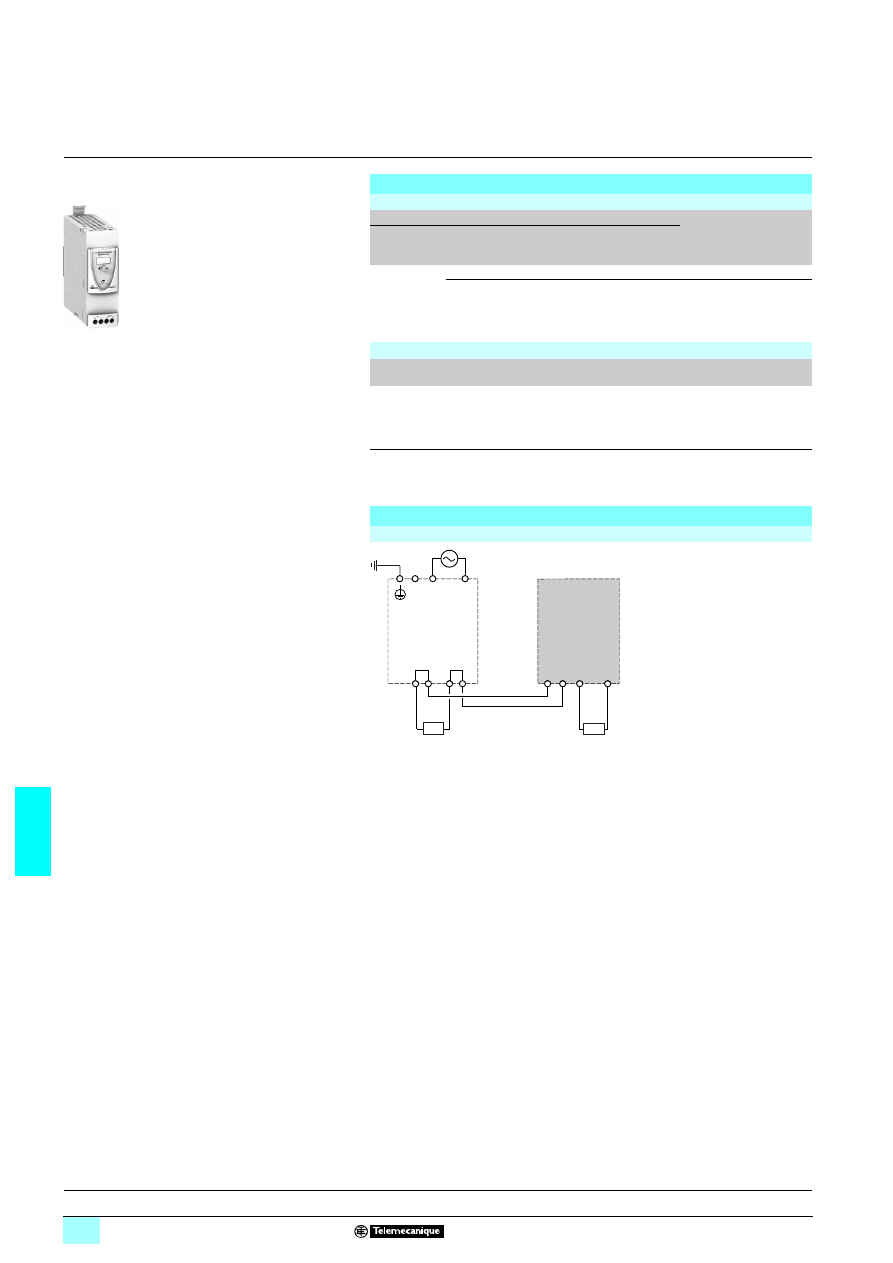
7/36
7
References,
connections
7
Power supplies and transformers
7
Regulated switch mode power supplies
Phaseo Universal range: Converter modules
References
4/4 converters
(for use with Universal range of Phaseo power supplies)
Primary (1)
Secondary
Reference
Weight
kg
Input voltage Universal range power
supply module output
current
Output
voltage
Nominal
current
24 V
3
- 9%,+ 24%
2.2 A
5...6.5 V
3 6 A
ABL 8DCC05060
0.300
1.7 A
7...15 V
3 2 A
ABL 8DCC12020
0.300
Replacement part
Designation
Composition
Unit reference
Weight
kg
Clip-on marker labels
Order in multiples
of 100
LAD 90
0.030
(1) Voltage from a 24 V
1 Phaseo Universal range power supply
Scheme of use with a Universal range power supply
With ABL 8DCC
77070 Converter module
ABL 8DCC050060/12020
c
24 V
c
5 V
+ +
c
c
ABL 8RPp24pp0
+
+
ABL 8DCCppppp
ABL 8DCC05060
c
12 V
ABL 8DCC12020
Out
In
–
–
–
–
a
Presentation:
page 7/34
Description:
page 7/34
Characteristics:
page 7/35
Dimensions:
page 7/37
Schemes:
page 7/37
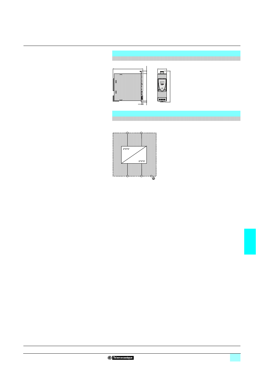
7/37
7
Dimensions,
internal scheme
7
Power supplies and transformers
7
Regulated switch mode power supplies
Phaseo Universal range: Converter modules
Dimensions
ABL 8DCC05060 and ABL 8DCC12020 Converter modules
Internal scheme
ABL 8DCC05060 and ABL 8DCC12020 Converter modules
12
140
44
+
IN
OUT
+
125
6
6
143
OUT
+
OUT
-
IN
+
IN
-
Presentation:
page 7/34
Description:
page 7/34
Characteristics:
page 7/35
References:
page 7/36
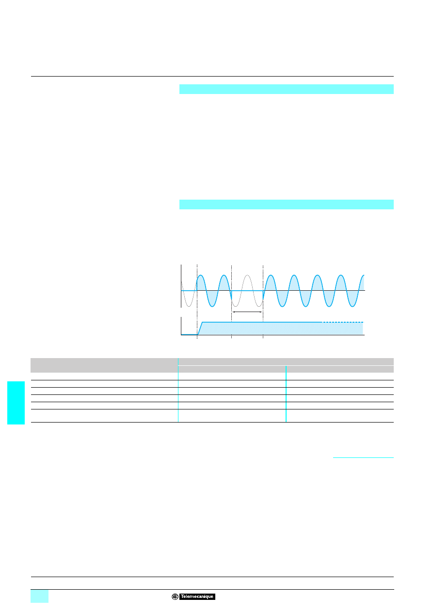
7/38
7
Presentation
7
Power supplies and transformers
7
Regulated switch mode power supplies
Phaseo Universal range: Function modules
Solutions to microbreaks and power outages
The ABL 8 Function module offer complements the ABL 8RPS/RPM/WPS electronic
switch mode power supply offer, thus forming a set of solutions to meet the needs for
continuity of service in the most demanding applications.
These modules, connected to the electronic switch mode power supply outputs, offer
solutions such as:
1 Immunity to microbreaks (see pages 7/38 to 7/45)
1 Voltage holding in the event of power outages (see pages 7/38 to 7/45)
1 Voltage holding in the event of power supply equipment failure (see pages 7/46 to
7/49)
1 Discrimination in the application's protection against overloads and short-circuits
(see pages 7/50 to 7/53)
ABL 8RPS/RPM/WPS power supplies can deliver their nominal power in the event
of a microbreak of less than 20 ms. When outages exceed this value, the
ABL 8BUF24400 Buffer Function module, combined with an ABL 8RPS/RPM/WPS
Universal power supply, is used. In the event of short interruptions, the Buffer module
takes over and continues to provide the 24 V
4 voltage. The table below indicates
the maximum time for immunity to microbreaks t1.
Note: In order to maximize the immunity time, it is advisable to connect only those circuits
requiring protection against microbreaks (controller or PLC power supply) at the Buffer module
output.
(1) Values liable to increase significantly. Please consult our website
www.telemecanique.com
Presentation
Continuity of service: Immunity to microbreaks
t1
t
t
Input voltage
Output voltage
Power supply
Typical time for immunity to microbreaks with Buffer module (40 A) at Un t1
100% load at the Buffer module output
2 A at the Buffer module output
ABL 8RPS24030
Single-phase or 2-phase 3 A, 72 W
0.912 s
0.984 s
ABL 8RPS24050
Single-phase or 2-phase 5 A, 120 W
0.472 s
1.33 s
ABL 8RPS24100
Single-phase or 2-phase 10 A, 240 W
0.220 s
1.34 s
ABL 8RPM24200
Single-phase or 2-phase 20 A, 480 W
0.206 s
1.82 s
ABL 8WPS24200
3-phase 20 A, 480 W
0.056 s (1)
1.18 s
ABL 8WPS24400
3-phase 40 A, 960 W
0.092 s (1)
1.29 s
Description:
page 7/40
Characteristics:
pages 7/42 and 7/43
References:
page 7/44
Dimensions:
page 7/45
Schemes:
page 7/45
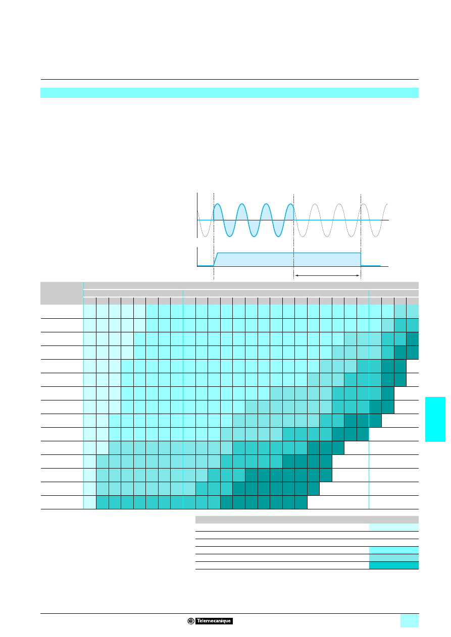
7/39
7
Presentation
(continued)
7
Power supplies and transformers
7
Regulated switch mode power supplies
Phaseo Universal range: Function modules
Solutions to microbreaks and power outages
For applications that are sensitive to unintended stopping, the ABL 8 range of
Function modules offers a solution comprising:
1 Electronic switch mode power supply and Buffer module for holding times t2 up to
two seconds
1 Electronic switch mode power supply, Battery check module and Battery module
for holding times t2 of between two seconds and a few hours
These solutions are used to supply voltage after loss of the line supply, thus enabling
saving of current values or fallback of some actuators supplied with 24 V
4.
The table below indicates the possible holding times according to the equipment
combinations and the current required.
Note: Several Buffer modules (up to a maximum of three) can be connected in parallel to
increase the immunity time. The times given in the table above (boxes marked 1) should be
multiplied by the number of modules used (2 or 3).
Continuity of service: Voltage holding in the event of a power outage (continued)
t2
t
t
Input voltage
Output voltage
Holding current Holding time t2
Seconds
Minutes
Hours
0.1
0.2
0.5
1
2
5
10
30
1
2
3
4
5
6
7
8
9
10
15
20
30
40
50
1
2
3
5
1 A
1
1
1
1
1
2+4 2+4 2+4 2+4 2+4 2+4 2+4 2+4 2+4 2+4 2+4 2+4 2+4 2+4 2+4 2+4 2+4 2+4 2+4 2+4 2+5 2+5
2 A
1
1
1
1
1
2+4 2+4 2+4 2+4 2+4 2+4 2+4 2+4 2+4 2+4 2+4 2+4 2+4 2+4 2+4 2+4 2+4 2+4 2+4 2+5 2+6 2+6
3 A
1
1
1
1
2+4 2+4 2+4 2+4 2+4 2+4 2+4 2+4 2+4 2+4 2+4 2+4 2+4 2+4 2+4 2+4 2+4 2+5 2+5 2+5 2+6 2+6 2+6
+6
4 A
1
1
1
1
2+4 2+4 2+4 2+4 2+4 2+4 2+4 2+4 2+4 2+4 2+4 2+4 2+4 2+4 2+4 2+4 2+5 2+5 2+5 2+5 2+6 2+6
+6
2+6
+6
5 A
1
1
1
2+4 2+4 2+4 2+4 2+4 2+4 2+4 2+4 2+4 2+4 2+4 2+4 2+4 2+4 2+4 2+4 2+5 2+5 2+5 2+6 2+6 2+6
+6
2+6
+6
6 A
1
1
1
2+4 2+4 2+4 2+4 2+4 2+4 2+4 2+4 2+4 2+4 2+4 2+4 2+4 2+4 2+4 2+5 2+5 2+5 2+6 2+6 2+6 2+6
+6
2+6
+6
7 A
1
1
1
2+4 2+4 2+4 2+4 2+4 2+4 2+4 2+4 2+4 2+4 2+4 2+4 2+5 2+5 2+5 2+5 2+5 2+6 2+6 2+6 2+6 2+6
+6
8 A
1
1
1
2+4 2+4 2+4 2+4 2+4 2+4 2+4 2+4 2+4 2+4 2+5 2+5 2+5 2+5 2+5 2+5 2+5 2+6 2+6 2+6 2+6
+6
2+6
+6
10 A
1
1
2+4 2+4 2+4 2+4 2+4 2+4 2+4 2+4 2+4 2+4 2+5 2+5 2+5 2+5 2+5 2+5 2+5 2+6 2+6 2+6
+6
2+6
+6
2+6
+6
15 A
1
1
2+4 2+4 2+4 2+4 2+4 2+4 2+4 2+4 2+4 2+5 2+5 2+5 2+5 2+5 2+6 2+6 2+6 2+6 2+6
+6
2+6
+6
2+6
+6
20 A
1
1
2+5 2+5 2+5 2+5 2+5 2+5 2+5 2+5 2+5 2+5 2+6 2+6 2+6 2+6 2+6 2+6 2+6
+6
2+6
+6
2+6
+6
25 A
1
3+5 3+5 3+5 3+5 3+5 3+5 3+5 3+5 3+5 3+5 3+6 3+6 3+6 3+6 3+6 3+6
+6
3+6
+6
3+6
+6
3+6
+6
30 A
1
3+5 3+5 3+5 3+5 3+5 3+5 3+5 3+5 3+5 3+6 3+6 3+6 3+6
+6
3+6
+6
3+6
+6
3+6
+6
3+6
+6
3+6
+6
3+6
+6
35 A
1
3+5 3+5 3+5 3+5 3+5 3+5 3+5 3+5 3+6 3+6 3+6 3+6
+6
3+6
+6
3+6
+6
3+6
+6
3+6
+6
3+6
+6
3+6
+6
40 A
1
3+6 3+6 3+6 3+6 3+6 3+6 3+6 3+6 3+6 3+6 3+6
+6
3+6
+6
3+6
+6
3+6
+6
3+6
+6
3+6
+6
3+6
+6
Function modules
Reference
Code
40 A Buffer module
ABL 8BUF24400
1
20 A Battery check module
ABL 8BBU24200
2
40 A Battery check module
ABL 8BBU24400
3
3.2 Ah Battery module
ABL 8BPK24A03
4
7 Ah Battery module
ABL 8BPK24A07
5
12 Ah Battery module
ABL 8BPK24A12
6
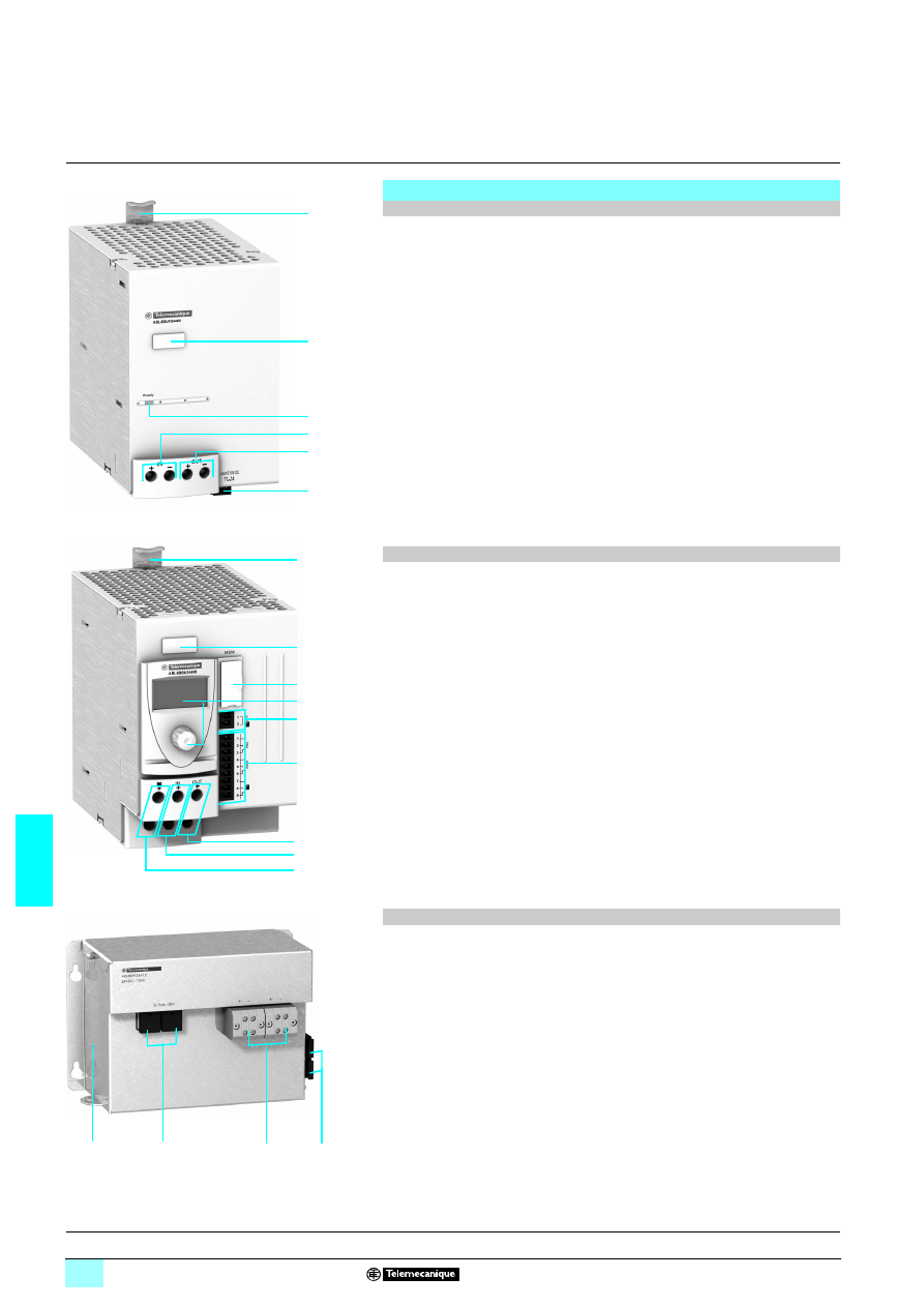
7/40
7
Description
7
Power supplies and transformers
7
Regulated switch mode power supplies
Universal Phaseo range: Function modules
Solutions to microbreaks and network power outages
The ABL 8BUF24400 Buffer Function module comprises:
1
Spring clip for 35 mm
6 rail
2
Clip-on marker label
3
LED indicator (green): module ready (maximum load)
4
10 mm
2
enclosed screw terminals for connection of the 24 V
4 input voltage
5
10 mm
2
enclosed screw terminals for connection of the 24 V
4 output voltage
6
Removable screw terminal block for connection of the diagnostic contact: module
ready (maximum load)
The ABL 8BBU24
700 Battery check Function modules comprises:
1
Spring clip for 35 mm
6 rail
2
Clip-on marker label
3
Memory card slot for backup and duplication of the configuration parameters
4
Display and configuration parameter browse/selection button
5
Removable screw connector for connection of the battery voltage inhibit input
3
This contact must always be volt-free.
6
Removable screw connector for connection of the diagnostic contacts (power
supply presence, battery alarm and presence)
7
10 mm
2
enclosed screw terminals for connection of the 24 V
4 output voltage
8
10 mm
2
enclosed screw terminals for connection of the power supply 24 V
4
input voltage
9
10 mm
2
enclosed screw terminals for connection of the battery voltage 24 V
4
input voltage
The front panel of the ABL 8BPK24A
77 Battery Function modules comprises:
1
A metal box that can be fixed on a vertical or horizontal panel
2
Fuse carrier (one or two depending on the model), which, in addition to protecting
the output, can be used to disable the battery module (fuse supplied but not fitted)
3
10 mm
2
enclosed screw terminals for connection of the Battery module 24 V
4
output voltage (depending on the model, allows two Battery modules to be
connected in parallel)
4
Fuse storage attachment
Description
40 A Buffer module
20 A and 40 A Battery check modules
3.2 Ah, 7 Ah, and 12 Ah Battery modules
6
4
2
1
3
5
9
8
7
6
3
2
5
1
2
1
4
4
3
Presentation:
pages 7/38 and 7/39
Characteristics:
pages 7/42 and 7/43
References:
page 7/44
Dimensions:
page 7/45
Schemes:
page 7/45
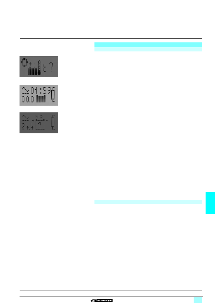
7/41
7
Functions
7
Power supplies and transformers
7
Regulated switch mode power supplies
Phaseo Universal range: Function modules
Solutions to microbreaks and power outages
The main module functions are:
1 Charging and checking the associated battery
1 Automatic switching between the power supply and the battery in the event of a
power outage
1 Diagnostics
The Battery check modules offer a three-color LCD screen and a navigation button that
can be used to:
1 Display the status and diagnostic data
1 Access the service and maintenance functions
1 Set the module parameters
These modules also have a diagnostic relay (C/O contacts) relating to:
1 The power supply status
1 The Battery module status
1 The alarm
The following functions are available:
1 Inhibition or activation (local or remote) of the battery to ensure the safety of
maintenance operations on the application and to avoid the battery discharging when
the installation is powered down
1 Battery test
1 Backup and download of a configuration via a memory card enabling storage and
duplication of the configuration parameters so as to eliminate repetitive operations
when setting up the Battery check modules
1 Firmware updating from a PC
The module parameters can be set in order to define:
1 The user language
1 The rating of the battery connected to the Battery check module
1 The operating temperature for the battery in order to optimize its life
1 The length and cross-section of the connection to compensate for voltage losses
due to the length of the line
1 The duration of the battery-powered supply
1 The threshold voltage provided by the power supply below which the battery takes
over
Whichever solution is used, the output terminals for the power supplies, Buffer
modules and Battery check modules have been designed to make it easier to isolate
a backed-up circuit and a non-backed-up circuit to ensure discrimination in continuity
of service after a power outage.
Each Battery module consists of:
1 Lead-sealed batteries (two in series)
1 Its automotive type fuse protection
Only these modules are compatible with the ABL 8BBU Battery check modules.
Functions
ABL 8BBU24
1111
00 Battery check modules
Green: Nominal
status/information
Orange: Warning
Red: Fault
Examples of Battery check module diagnostic screens
ABL 8BPK24A
11
11
11
11 Battery modules
Presentation:
pages 7/38 and 7/39
Characteristics:
page 7/42
References:
page 7/44
Dimensions:
page 7/45
Schemes:
page 7/45
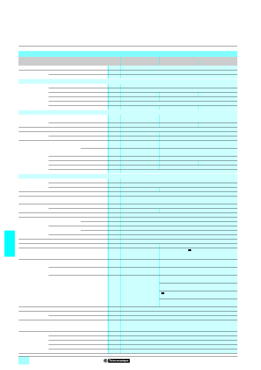
7/42
7
Characteristics
7
Power supplies and transformers
7
Regulated switch mode power supplies
Phaseo Universal range: Function modules
Solutions to microbreaks and power outages
Technical characteristics
Type of Function module
Buffer module
Battery check module
ABL 8BUF24400
ABL 8BBU24200
ABL 8BBU24400
Certifications
CB scheme EN60950-1, UL (pending), cCSAus
Conformity to
standards
Safety
EN60950-1, EN61204
EMC
IEC/EN61000-6-2, IEC/EN61000-6-3
Input circuit
Input values
Nominal voltage
V
24...28.8
3
Limit voltage
V
22...30
3
No-load/On-load/Max. consumption
A
0.1/0.6/40.6
0.1/1.7/21.7
0.1/1.7/41.7
Activation threshold
V
U
In
- 1 and 22
3 min.
Adjustable 22...26
3
Protection against reverse polarity
Yes
Dissipated power at nominal load
W
< 15
< 7
< 12
Output circuit
Nominal output
values
Voltage (U
Out
)
V
Nominal mode: U
In
-0.25
Buffer mode: U
In
-1
Nominal mode: U
In
-0.25
Battery mode: U
battery
-0.5
Max. current
A
40
20
40
Precision
Residual ripple - noise
mV
< 200
Holding time
I = 0.5 A
6 s
See page 7/39
I = 40 A
0.1 s
See page 7/39
Protection
Against short-circuits
Power-supplied
mode
Permanent,
automatic restart
Power supply protection
Battery-backed
mode
–
Permanent, automatic restart
Against overloads
> 45 A
1.5 In
Against overvoltages
V
–
–
–
Against undervoltages
V
Tripping if U
Out
< 19
–
Thermal
–
Operating and environmental characteristics
Connections
Input
mm
2
2 x 0.5...10 screw terminals (20...8 AWG)
Output
mm
2
2 x 0.5...10 screw terminals (20...8 AWG)
Diagnostic relay
mm
2
2.5
0.75
Mounting
On
4 rail
35 x 7.5 mm and 35 x 15 mm
Operating position Vertical plane
Mounted vertically
Mounted horizontally (with derating of maximum power by 20% from 50°C)
Connections
Series
–
Parallel
Yes
–
Degree of protection
IP 20 conforming to IEC 60529
Environment
Temperature Operation
°C
- 25…+ 60
Storage
°C
- 40…+ 85
Relative humidity
Operation
90%
Storage
95%
Vibration acc. to EN 61131-2
3...11.9 Hz amplitude 3.5 mm; 11.9... 150 Hz acceleration 2 g
Protection class according to VDE 0106 1
Class II
Charging time
s
< 25
Depending on the battery used
Control input
–
Battery inhibit input
/OFF: terminals 1 and 2 linked =
battery off
3
This contact must always be volt-free.
Diagnostics
Via LED
Green: Buffer ready
Off: Load < 95%
–
LCD screen
–
Green: nominal status, orange: warning,
red: fault
Via relay
Open: Load < 95%
Closed: Buffer ready
3 C/O relays: for power supply status, battery and alarm
status
PSU: relay tripped (contact 1-2 closed): 24 V present on
In input
: relay tripped (contact 4-5 closed): backup mode,
current supplied by the battery
Alarm: relay tripped (contact 7-8 closed): battery charge
< 80% battery off or disconnected
Relay characteristic
230 V
120.5 A, 24 V 3 5 mA min.
Dielectric strength
50 Hz for 1 min
Input/ground
V rms
500
1
Output/ground
V rms
500
1
Emissions
according to
EN 61000-6-3
Conducted/radiated
EN 55022 - Class B
Immunity
according to
EN 61000-6-2
Electrostatic discharge
IEC/EN 61000-4-2 (6 kV contact/8 kV air)
Radiated electromagnetic fields
IEC/EN 61000-4-3 level 3 (10 V/m)
Induced electromagnetic fields
IEC/EN 61000-4-6 level 3 (10 V/m)
Rapid transients
IEC/EN 61000-4-4 level 3 (2 kV)
Surges
IEC/EN 61000-4-5 level 2 (1 kV)
+
+
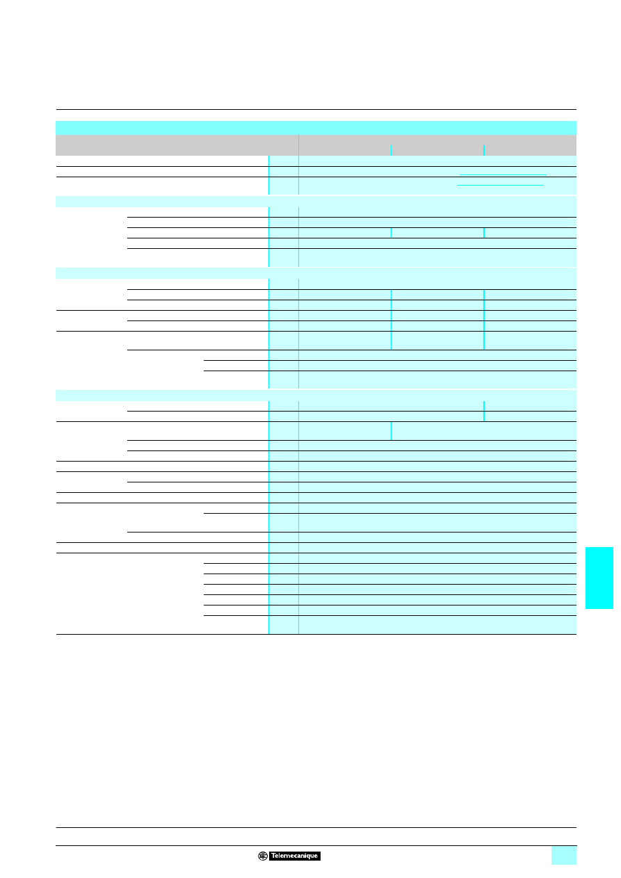
7/43
7
Characteristics
(continued)
7
Power supplies and transformers
7
Regulated switch mode power supplies
Phaseo Universal range: Function modules
Solutions to microbreaks and power outages
(1) With mounting kit on ABL 1A02 rail
Technical characteristics
Type of Function module
Battery
ABL 8BPK24A03
ABL 8BPK24A07
ABL 8BPK24A12
Battery type
Lead-sealed battery
Certifications
Certification pending, please consult our website
www.telemecanique.com
Conformity to standards
Safety
Conformity pending, please consult our website
www.telemecanique.com
Input circuit
Input values
Nominal voltage
V
24...28.8
3
Limit voltage
V
22...29
3
Load current
A
0.3
0.7
1.2
Protection against reverse polarity
Yes
Charging time
h
72 max.
Output circuit
Nominal output
values
Voltage (Un)
V
24
3
Max. current
A
32
40
75
Capacity
Ah
3.2
7
12
Holding time
at 20°C
Maximum
h
20 at 0.16 A
20 at 0.35 A
20 at 0.6 A
Minimum
min
5 at 8.4 A
5 at 18.2 A
5 at 31.3 A
Protection
Against short-circuits and overloads by
automotive type fuse protection
1 x 20 A
1 x 30 A
2 x 30 A
Self-discharge rate
1 month
3%
3 months
9%
6 months
15%
Operating and environmental characteristics
Connections
Input
mm
2
2 x 0.5...10 (20...6 AWG)
4 x 0.5...10 (20...6 AWG)
Output
mm
2
2 x 0.5...10 (20...6 AWG)
4 x 0.5...10 (20...6 AWG)
Mounting
On
6
rail
35 x 7.5 mm and 35 x
15 mm (1)
–
On vertical panel
With 4 screws
∅
5 mm
On horizontal panel
With 2 screws
∅
5 mm
Operating position
Vertical or horizontal
Connections
Series
–
Parallel
Yes
Degree of protection
IP 10 conforming to IEC 60529
Environment
Temperature
Operation
°C
0…+ 40
Storage
°C
- 20…+ 50
Vibration acc. to EN 61131-2
3...11.9 Hz amplitude 3.5 mm and 11.9 -150 Hz acceleration 2 g
Protection class according to VDE 0106 1
Class III
Service life
(approximate)
20°C
h
44,000
25°C
h
31,000
30°C
h
22,000
35°C
h
15,000
40°C
h
11,000
45°C
h
7,300
50°C
h
5,000
Presentation:
pages 7/38 and 7/39
Description:
page 7/40
References:
page 7/44
Dimensions:
page 7/45
Schemes:
page 7/45
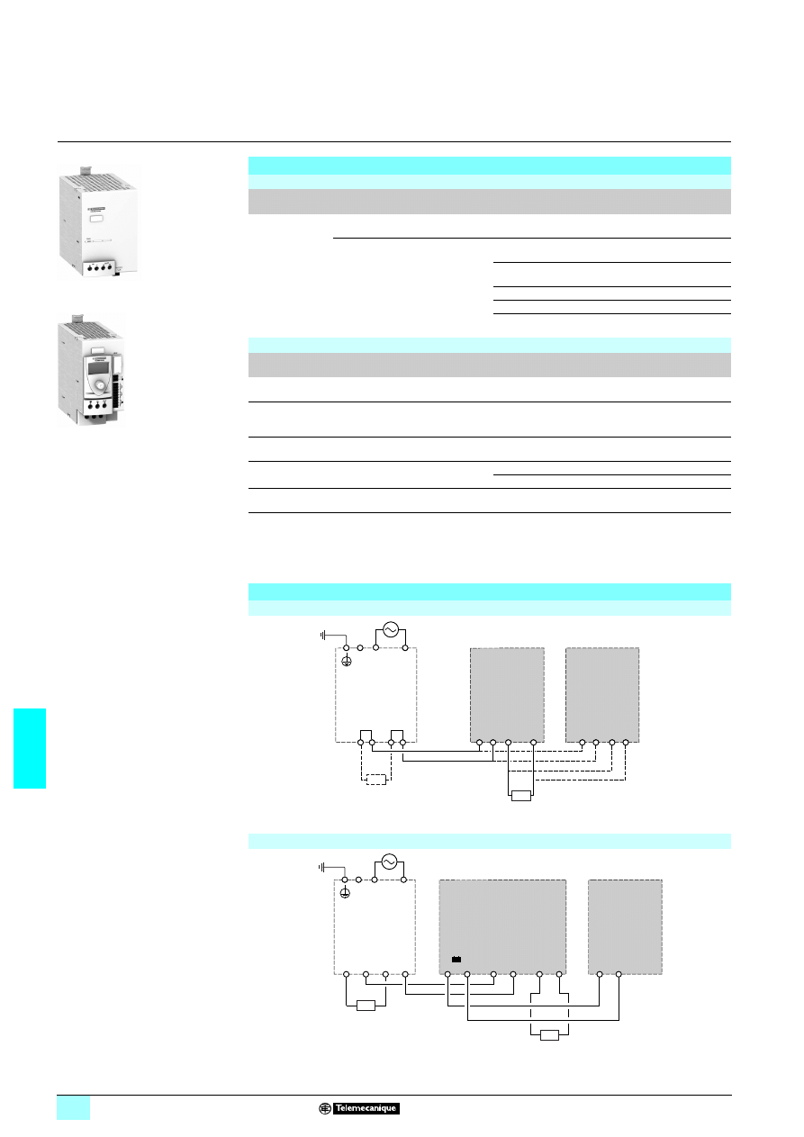
7/44
7
References,
connections
7
Power supplies and transformers
7
Regulated switch mode power supplies
Phaseo Universal range: Function modules
Solutions to microbreaks and power outages
References
Function modules
Function
Use
Designation
Reference
Weight
kg
Continuity after a
power outage
Holding time 100 ms at 40 A and 2 s at
1 A
Buffer module
ABL 8BUF24400
1.200
Holding time 9 min at 40 A...2 hrs at
1 A (depending on use with a battery
check module-battery unit and load)
(1)
Battery check module
20 A output current
ABL 8BBU24200
4
4
4
4
0.500
Battery check module,
40 A output current
ABL 8BBU24400
4
4
4
4
0.700
3.2 Ah battery module (2) ABL 8BPK24A03
4
4
4
4
3.500
7 Ah battery module (2)
ABL 8BPK24A07
4
4
4
4
6.500
12 Ah battery module (2)
ABL 8BPK24A12
4
4
4
4 12.000
Separate and replacement parts
Designation
Description
Composition
Unit reference
Weight
kg
Fuse assemblies
For ABL 8BKP24A
55 battery
4 x 20 A and 6 x 30 A
ABL 8FUS02
–
Clip-on marker
labels
All products except ABL 8PR
555555
Order in multiples of 100
LAD 90
0.030
Kit for mounting
on
4 rail
For ABL 8BPK2403 Battery module
Single unit
ABL 1A02
–
Cables
Connection cable between ABL8 BBU
and PC for updating the software
RS232 3 m
SR2CBL01
0.150
USB 3 m
SR2USB01
0.150
EEPROM memory Backup and duplication of ABL8 BBU
parameters
Single unit
SR2MEMO2
0.010
(1) For table of compatibility of battery check module-battery unit with holding time depending on the load,
see page 7/39.
(2) Supplied with 20 or 30 A fuse depending on the model.
.
8 Available 2
nd
quarter 2007
Schemes of use with a Universal range power supply
With ABL 8BUF24400 Buffer module
With ABL 8BBU24
700 Battery check module
ABL 8BUF24400
ABL 8BBU24200
c
24 V
c
24 V
+
+
+
+
c
c
+
+
ABL 8BUF24400
ABL 8BUF24400
Out
In
Out
In
–
–
–
–
–
–
a
ABL 8RPp24pp0
ABL 8WPS24p00
Load saved
Load not
saved
c
24 V
c
24 V
+
+
+
ABL 8RPp24pp0
ABL 8WPS24p00
+
+
ABL 8BPK24App
ABL 8BBU24p00
OUT
IN
–
–
–
–
–
+
–
+
a
Load saved
Load not
saved
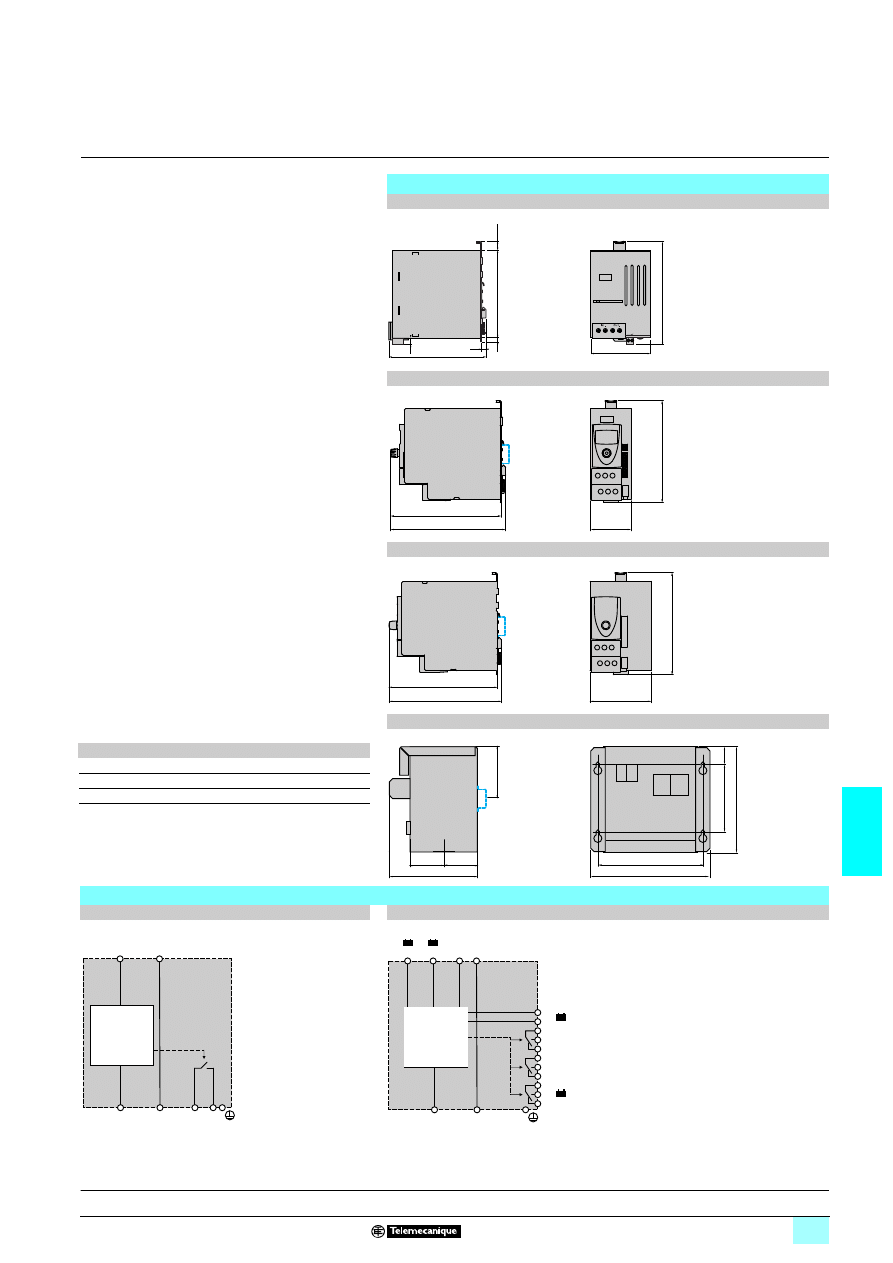
7/45
7
Dimensions,
internal schemes
7
Power supplies and transformers
7
Regulated switch mode power supplies
Phaseo Universal range: Function modules
Solutions to microbreaks and power outages
Dimensions
ABL 8BUF24400 Buffer module
ABL 8BBU24200 Battery check module
ABL 8BBU24400 Battery check module
ABL 8BPK24A03/A07/A12 Battery modules
+
+
11
14
85
140
12
125
146
6
6
9
60
153
158
141
85
153
158
141
b
c
G
J
27
a
K
=
=
Internal schemes
ABL 8BUF24400 Buffer module
ABL 8BBU24200 and ABL 8BBU24400 Battery check modules
OUT
+
OUT
-
IN
+
IN
-
11
14
OUT
+
OUT
-
IN
+
+
IN
-
-
PSU
ALARM
Terre fonctionnelle
+
+
+
OFF
+
1
2
3
4
5
6
7
8
1
2
9
Presentation:
pages 7/38 and 7/39
Description:
page 7/40
Characteristics:
pages 7/42 and 7/43
References:
page 7/44
ABL 8BKP a
b
c
G
J
K
24A03
97
185
140
157
83
78
24A07
133
170
158
152
100
–
24A12
130
237
157
219
100
–
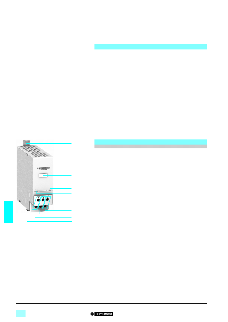
7/46
7
Presentation,
description
7
Power supplies and transformers
7
Regulated switch mode power supplies
Phaseo Universal range: Function modules
Redundancy solution
Where continuous operation of the application is the prime concern, it is necessary
to ensure that when one power supply malfunctions, a second power supply takes
over. The ABL 8RED24400 Redundancy module can perform this function, ensuring
that the failure of one power supply does not disturb the second (for example, in the
event of a short-circuit of one of the power supply outputs).
The ABL 8RED24400 Redundancy module, used with two electronic switch mode
power supplies of the same type, can be used to supply the nominal power to the
application even if one of the power supplies fails.
The various diagnostics - on the front panel (LED) and remote (relay) - inform the
maintenance team as soon as the first fault occurs on one of the power supplies.
When continuity of service is critical for the application, it may be necessary to
provide redundancy for the Redundancy module. A special connection is detailed in
the user manual (downloadable from the
telemecanique.com
website).
Note: The Redundancy module can be used to connect two power supplies with a maximum
rating of 20 A in parallel. To connect two 40 A ABL 8WPS24400 power supplies, two
ABL 8RED24400 Redundancy modules must be used.
The ABL 8RED24400 Redundancy Function module comprises:
1
Spring clip for 35 mm
6 rail
2
Clip-on marker label
3
Input voltage status LED (green) for the first 24 V
4 power supply
4
Input voltage status LED (green) for the second 24 V
4 power supply
5
10 mm
2
enclosed screw terminals for connection of the 24 V
4 output voltage
6
10 mm
2
enclosed screw terminals for connection of the input voltage for the
second 24 V
4 power supply (I 9 20 A)
7
10 mm
2
enclosed screw terminals for connection of the input voltage for the
first 24 V
4 power supply (I 9 20 A)
8
Removable screw terminal block for connection of the diagnostic contact: power
supply connected to a faulty input
Continuity of service: Failure of power supply equipment
Description
2 x 20 A Redundancy module
2
1
4
3
7
6
5
8
Characteristics:
page 7/47
References:
page 7/48
Dimensions:
page 7/49
Schemes:
page 7/49
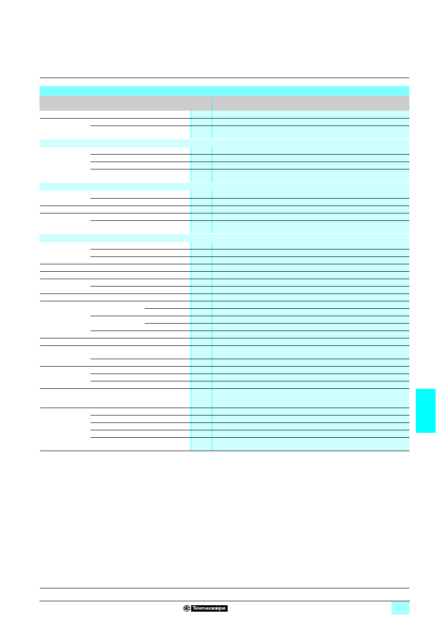
7/47
7
Characteristics
7
Power supplies and transformers
7
Regulated switch mode power supplies
Phaseo Universal range: Function modules
Redundancy solution
Technical characteristics
Type of Function module
Redundancy
ABL 8RED24400
Certifications
CB scheme EN60950-1, UL (pending), cCSAus
Conformity to
standards
Safety
EN60950-1, EN61204
EMC
EN61000-6-2, EN61000-6-3
Input circuit
Input values
Nominal voltage (U
In
)
V
24...28.8
3
Limit voltage
V
22...30
3
Input limit current
A
20 per input
Protection against reverse polarity
Yes
Output circuit
Nominal output
values
Output voltage (U
Out
)
V
U
In
- 0.2
Max. current (I
Out
)
A
40
Number of channels
1
Protection
Against short-circuits
Provided by the power supply
Against overloads
Manual, provided by the power supply
Operating and environmental characteristics
Connections
Input
mm
2
2 x 0.5...10 (20...8 AWG)
Output
mm
2
2 x 0.5...10 (20...8 AWG)
Diagnostic relay
mm
2
2.5
Mounting
On
4 rail
35 x 7.5 mm and 35 x 15 mm
Operating position Vertical plane
Vertical or horizontal position
Connections
Series
–
Parallel
Yes for 2 x 40 A
Degree of protection
IP 20 conforming to IEC 60529
Environment
Temperature Operation
°C
- 25…+ 60
Storage
°C
- 40…+ 85
Relative humidity
Operation
90%
Storage
95%
Vibration acc. to EN 61131-2
3...11.9 Hz amplitude 3.5 mm; 11.9... 150 Hz acceleration 2 g
Protection class according to VDE 0106 1
Class II
Diagnostics
Via LED
1 LED per input
Green: power supply operational
Via relay
Closed: 2 power supplies operational
Dielectric strength
50 Hz for 1 min
Input/output
V rms
No isolation
Input/ground
V rms
500
1
Output/ground
V rms
500
1
Emissions
according to
EN 61000-6-3
Conducted/radiated
EN 55022 - Class B
Immunity
according to
EN 61000-6-2
Electrostatic discharge
IEC/EN 61000-4-2 (6 kV contact/8 kV air)
Radiated electromagnetic fields
IEC/EN 61000-4-3 level 3 (10 V/m)
Induced electromagnetic fields
IEC/EN 61000-4-6 level 3 (10 V/m)
Rapid transients
IEC/EN 61000-4-4 level 3 (2 kV)
Surges
IEC/EN 61000-4-5 level 2 (1 kV)
Description:
page 7/46
References:
page 7/48
Dimensions:
page 7/49
Schemes:
page 7/49
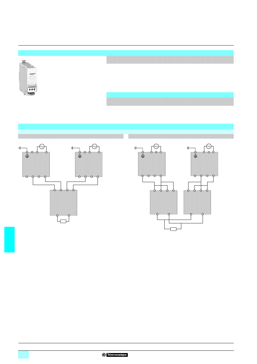
7/48
7
References,
connections
7
Power supplies and transformers
7
Regulated switch mode power supplies
Phaseo Universal range: Function modules
Redundancy solution
Function module
ABL 8RED24400
Function
Use
Designation
Reference
Weight
kg
Continuity
after a failure
Paralleling and redundancy of
the power supply to ensure
uninterrupted operation of the
application excluding AC line
failures and application
overloads
Redundancy module ABL 8RED24400
0.700
Replacement part
Designation
Composition
Unit reference
Weight
kg
Clip-on marker labels
Order in multiples
of 100
LAD 90
0.030
Schemes of use with Universal range power supplies
With ABL 8RED24400 Redundancy module
ABL 8RPS24
111
111
111
111/ABL 8RPM24200/ABL 8WPS24200
ABL 8WPS24400 or full system redundancy
c 24 V
+
+
+
+
IN1
IN2
+
OUT
ABL8RED24400
+
+
In y 20 A
–
–
–
–
–
–
–
a
a
ABL 8RPp24pp0
ABL 8WPS24200
ABL 8RPp24pp0
ABL 8WPS24200
+
+
+
+
IN1
IN2
ABL8
+
OUT
ABL8RED24400
c 24 V
+
+
IN1
IN2
+
OUT
ABL8RED24400
+
+
ABL8
In = 40 A
–
–
–
–
–
–
–
–
–
–
a
a
Description:
page 7/46
Characteristics:
page 7/47
Dimensions:
page 7/49
Schemes:
page 7/49
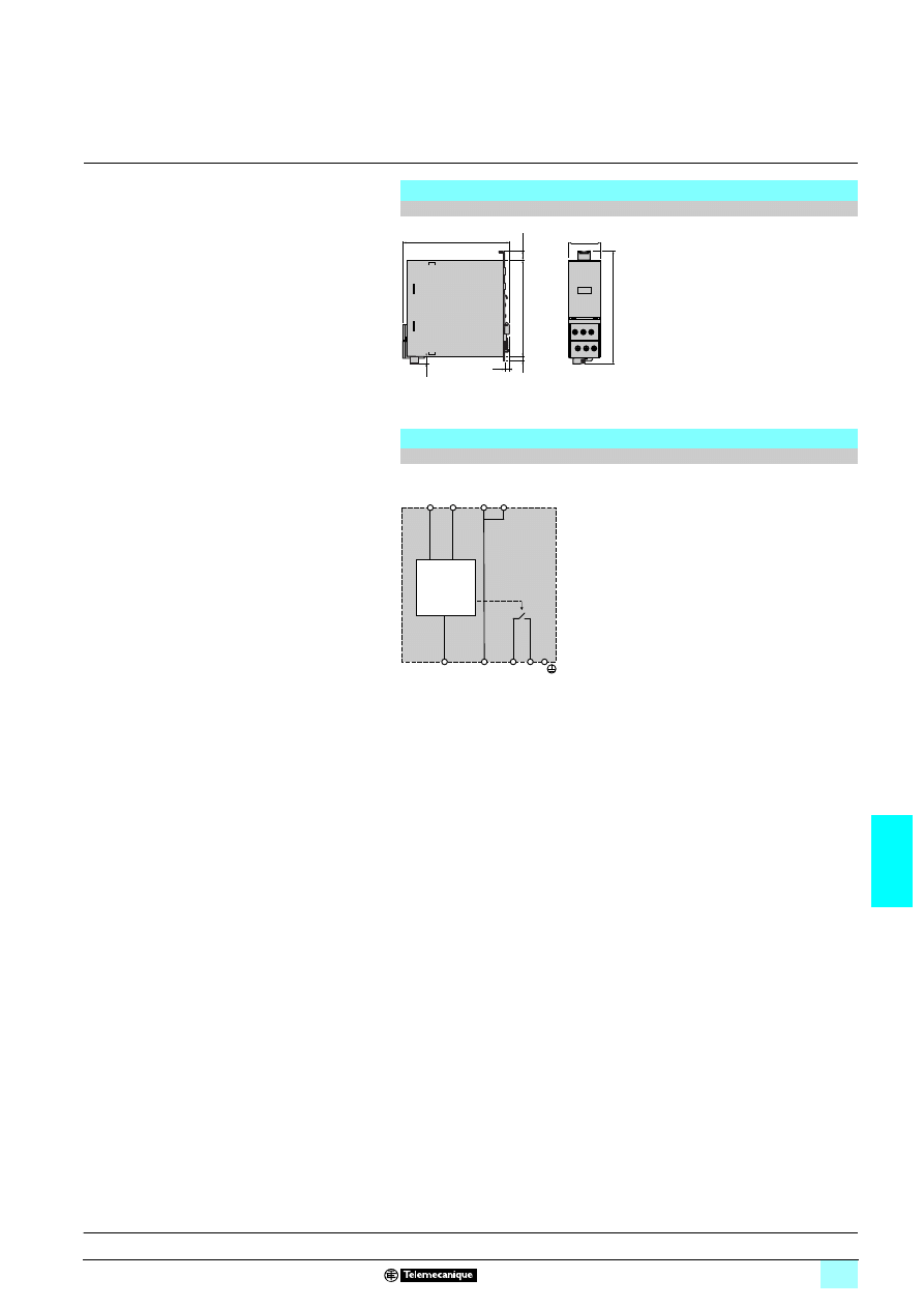
7/49
7
Dimensions,
internal scheme
7
Power supplies and transformers
7
Regulated switch mode power supplies
Phaseo Universal range: Function modules
Redundancy solution
Dimensions
ABL 8RED24400 Redundancy module
Internal scheme
ABL 8RED24400 Redundancy module
140
44
IN
1
+
+
+
146
9
12
125
6
6
OUT
+
OUT
-
IN1
+
IN2
+
IN1
-
IN2
-
11 14
Description:
page 7/46
Characteristics:
page 7/47
References:
page 7/48
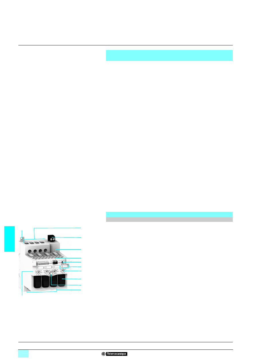
7/50
7
Presentation,
description
7
Power supplies and transformers
7
Regulated switch mode power supplies
Phaseo Universal range: Function modules
Solution for discriminating protection of the application
There is no point in using thermal-magnetic circuit-breakers or fuses downstream of
an electronic switch mode power supply in the majority of cases. When a short-circuit
or very quick overload occurs in the application, the electronic protection is faster
than the thermal-magnetic circuit-breaker or fuse. In this case, none of the circuits
are powered.
To provide discriminating protection in the event of an overload or short-circuit, the
Universal Phaseo power supply electronic protection function has been integrated in
four-channel modules. These discriminating downstream Protection modules can be
daisy-chained to provide protection discrimination on as many application segments
as necessary.
There are two references available for this solution:
1 ABL 8PRE24100: Optimum discriminating downstream electronic Protection
module with single-pole breaking
1 ABL 8PRP24100: Universal discriminating downstream electronic Protection
module with 2-pole breaking
The ABL 8PR
724100 discriminating downstream Protection modules have:
1 Overload and short-circuit protection on each of their four channels:
23Each channel can be calibrated by the user from 1 to 10 A, according to the needs
of the application.
23The breaking capacity is provided by one fuse per channel that can be calibrated
according to the line (factory setting 15 A).
1 Memorization of the fault even in the event of failure of the 24 V 4 voltage to be
protected
1 One diagnostic LED per channel
1 Manual reset on the front panel
1 One switch per channel that can be used, like thermal-magnetic circuit-breakers,
to open or close the circuits during test, maintenance or installation periods
In addition, the ABL 8PRP24100 module has:
1 A 2-pole isolator on each of its channels
1 An automatic or manual reset mode for the protection
1 A diagnostic relay indicating that all channels are operational
The ABL 8PR
724100 4-channel downstream electronic Protection modules
comprises:
1
10 mm
2
enclosed screw terminals for connection of the 24 V
4 voltage to be
protected
2
Enclosed screw terminals for connection of the diagnostic relay contact (on
ABL 8PRP24100 model only)
3
Line protection fuses (one 15 A fuse per channel by default)
4
Automatic or manual reset mode selector (on ABL 8PRP24100 model only)
5
Reset pushbutton (on ABL 8PRP24100 model only)
6
Diagnostic LEDs (green and red) and clip-on marker tag holder (1 per channel)
7
1...10 A output nominal current selector (1 per channel)
8
Channel isolator switch (1 per channel)
9
Locking catch for the glass flap (sealable).
10
4 mm
2
enclosed screw terminals for connection of the four channels: single-pole
(with ABL 8PRE24100 model) or 2-pole (with ABL 8PRP24100 model)
11
Protective glass flap
12
Retractable fixing lugs for panel mounting (
6 rail mounting also possible)
Continuity of service: Discrimination of protection against
overloads and short-circuits
Description
Single-pole and 2-pole downstream electronic Protection modules
1
2
3
4
5
6
7
8
10
9
12
11
Characteristics:
page 7/51
References:
page 7/52
Dimensions:
page 7/53
Schemes:
page 7/53
7/51
7
Characteristics
7
Power supplies and transformers
7
Regulated switch mode power supplies
Phaseo Universal range: Function modules
Solution for discriminating protection of the application
Technical characteristics
Type of Function module
Discriminating downstream electronic protection
ABL 8PRE24100
ABL 8PRP24100
Certifications
CB scheme EN60950-1, UL (pending), cCSAus
Conformity to
standards
Safety
EN60950-1, EN61204
EMC
EN61000-6-2, EN61000-6-3
Input circuit
Input values
Nominal voltage
V
24...28.8
3
Limit voltage
V
19...32
3
Input limit current
A
40
Protection against reverse polarity
Yes
Output circuit
Nominal output
values
Voltage (U
Out
)
V
U
In
- 0.3 V
Max. current (I
Out
)
A
10 per channel
Rating
A
1/2.5/4/5/7/8/10 per channel
Number of channels
4
Protection
Against short-circuits
Permanent, manual restart
Permanent, automatic or manual restart
Against overloads
1.3 In
1.3 In
Isolation
Type
Single-pole switch (+ 24 V)
2-pole switch (+ 24 V and 0 V)
Breaking capacity (fuse)
1000 A at 32 V
3
Operating and environmental characteristics
Connections
Input
mm
2
4 x 0.5...10 (20...8 AWG)
Output
mm
2
4 x 0.5...4 (20...10 AWG)
8 x 0.5...4 (20...10 AWG)
Diagnostic relay
mm
2
2.5
Mounting
On
12
rail
35 x 7.5 mm and 35 x 15 mm
Operating position Vertical plane
Mounted vertically
Degree of protection
IP 20 conforming to IEC 60529
Environment
Temperature Operation
°C
- 25…+ 60
Storage
°C
- 40…+ 85
Relative humidity
Operation
90%
Storage
95%
Vibration acc. to EN 61131-2
3...11.9 Hz amplitude 3.5 mm; 11.9... 150 Hz acceleration 2 g
Protection class according to VDE 0106 1
Class II
Diagnostics
Via LED
1 LED per channel
Green: Channels operating
Red: Overload
Off: U
In
< 19 V or switch open
Via relay
–
Closed: Channels operating
Open: If 1 channel faulty
Dielectric strength
50 Hz for 1 min
Input/output
V rms
No isolation
Input/ground
V rms
500
1
Output/ground
V rms
500
1
Emissions
according to
EN 61000-6-3
Conducted/radiated
EN 55022-Class B
Immunity
according to
EN 61000-6-2
Electrostatic discharge
IEC/EN 61000-4-2 (6 kV contact/8 kV air)
Radiated electromagnetic fields
IEC/EN 61000-4-3 level 3 (10 V/m)
Induced electromagnetic fields
IEC/EN 61000-4-6 level 3 (10 V/m)
Rapid transients
IEC/EN 61000-4-4 level 3 (2 kV)
Surges
IEC/EN 61000-4-5 level 2
(1 kV)
Description:
page 7/50
References:
page 7/52
Dimensions:
page 7/53
Schemes:
page 7/53
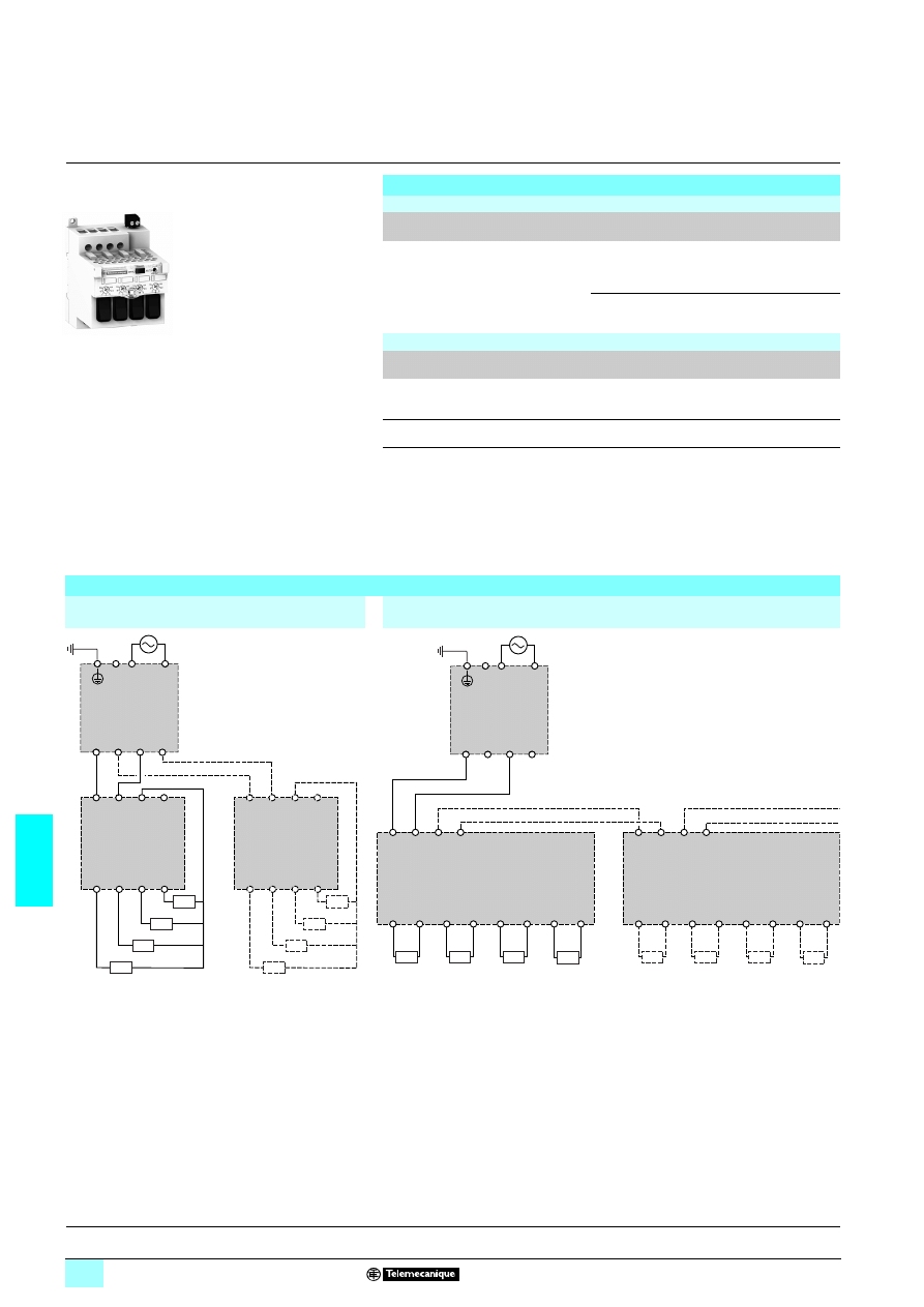
7/52
7
References,
connections
7
Power supplies and transformers
7
Regulated switch mode power supplies
Phaseo Universal range: Function modules
Solution for discriminating protection of the application
References
Function modules: Discriminating downstream Protection
Function
Use
Designation
Reference
Weight
kg
Discriminating
downstream
protection
Electronic protection
(1...10 A overload or
short-circuit) of 4 output
terminals from a Phaseo
Universal range power
supply
Optimum Protection
module with
single-pole breaking
(1) (3)
ABL 8PRE24100
4
4
4
4
–
Universal Protection
module with 2-pole
breaking (2) (3)
ABL 8PRP24100
4
4
4
4
–
Replacement parts
Designation
Description
Composition
Unit reference
Weight
kg
Fuse
assemblies
For ABL 8PR
524100
discriminating Protection
modules
4 x 3 A, 4 x 7.5 A and 4
x 15 A
ABL 8FUS01
–
Clip-on marker
labels
ABL 8PR
555555
Order in multiples of
22
ASI20MACC5
–
(1) Local reset via pushbutton
(2) Local reset via pushbutton or automatic reset on elimination of the fault
(3) Supplied with four 15 A fuses
8 Available 2
nd
quarter 2007
Connections
With ABL 8PRE24100 downstream electronic
Protection module
With ABL 8PRP24100 downstream electronic Protection module
c
24 V
c
24 V
c
24 V
c
24 V
+
+
ABL 8PRE24100
+
+
ABL 8RPp24p00
ABL 8WPS24p00
–
–
–
–
+
+
+
+
a
c
24 V
c
24 V
c
24 V
c
24 V
+
+
ABL 8PRE24100
–
–
+
+
+
+
c
24 V
c
24 V
c
24 V
c
24 V
+
+
IN1
IN2
OUT1
ABL 8PRP24100
+
+
ABL 8RPp24pp0
ABL 8 WPS24p00
–
–
–
–
+
–
OUT2
+
–
OUT3
+
–
OUT4
+
–
c
24 V
c
24 V
c
24 V
c
24 V
+
+
IN1
IN2
OUT1
ABL 8PRP24100
–
–
+
–
OUT2
+
–
OUT3
+
–
OUT4
+
–
a
3
IN1 and IN2 terminals limited to 40 A
Description:
page 7/50
Characteristicss:
page 7/51
Dimensions:
page 7/53
Schemes:
page 7/53
ABL 8PRP24100
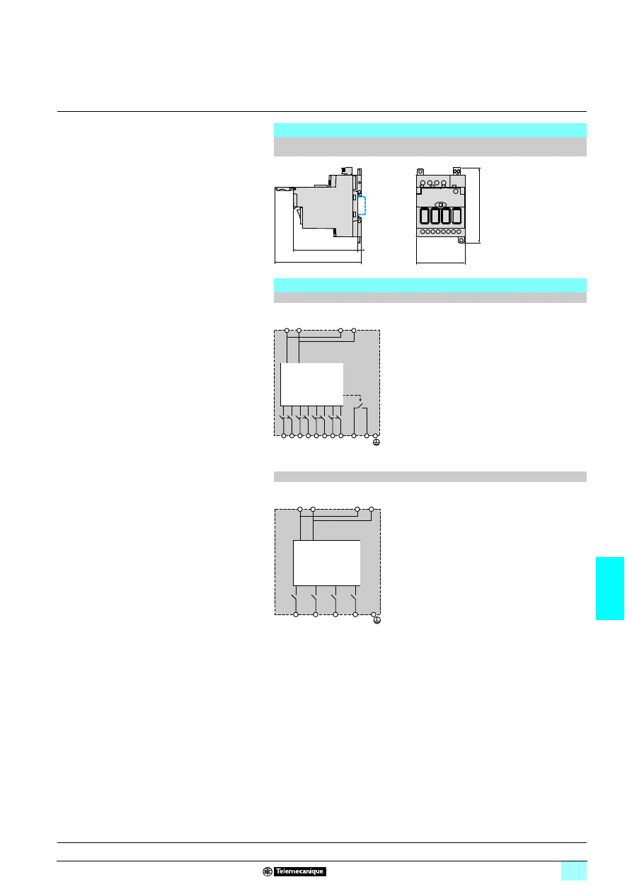
7/53
7
Dimensions,
internal schemes
7
Power supplies and transformers
7
Regulated switch mode power supplies
Phaseo Universal range: Function modules
Solution for discriminating protection of the application
Dimensions
ABL 8PRE24100 and ABL 8PRP24100 discriminating downstream electronic Protection
modules
Internal schemes
ABL 8PRP24100 downstream electronic Protection module (2-pole breaking)
ABL 8PRE24100 downstream electronic Protection module (single-pole breaking)
Note: The 0 V (- Out) polarities are not distributed on this module. They must therefore be wired
externally to the module by the user.
103
136
11
0
71
6
IN
+
IN
-
11
14
+
OUT 1
-
OUT 2
OUT 3
OUT 4
+ -
+ - + - + -
IN
IN
+ -
+ -
+
OUT 1
+
OUT 2
+
OUT 3
+
OUT 4
IN
IN
IN
IN
Description:
page 7/50
Characteristics:
page 7/51
References:
page 7/52
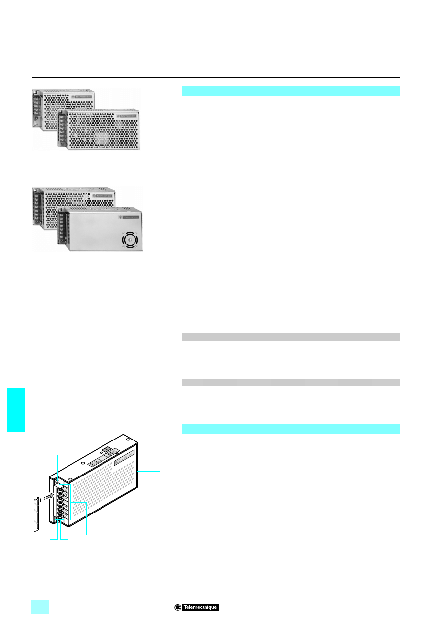
7/54
7
Presentation,
description
7
Power supplies and transformers
7
Power supplies for DC control circuits
Regulated switch mode power supplies
Phaseo Dedicated range
ABL 1REM/RPM Phaseo Dedicated range regulated switch mode power supplies
are specially designed to provide the d.c. voltage necessary for electrical equipment
operating on a safety extra low voltage (SELV). Split into two ranges, they are able
to meet all the needs encountered in standard commercial machines.
These single-phase power supplies, with or without anti-harmonic distortion filter,
conform to world-wide standards. Switch mode technology guarantees the quality of
the output current with regulation below 3%.
As machine components, ABL 1REM/RPM Phaseo Dedicated range power supplies
must be easy to install; only setting-up may vary from one application to another. The
ABL 1 range has been specially designed for machine manufacturers.
ABL 1REM/RPM regulated switch mode power supplies are totally electronic and
regulated. They provide the following benefits:
1 A wide input voltage range from 85 to 264 V 5 and 120 to 370 V 4 (not indicated
on the product).
1 Products with anti-harmonic distortion input filter.
1 A high degree of output voltage stability, adjustable by potentiometer.
1 Built-in thermal overload protection.
1 Conformity to world-wide standards.
1 Conformity to standard EN 55022 class B.
1 UL 508, CSA and TÜV certifications.
1 Overload and short-circuit protection.
1 Considerably reduced weight.
1 Identical mounting accessories for all models.
ABL 1 power supplies for electrical equipment are split into two ranges :
1 ABL 1REM, single-phase:
2360 W for the 12 V 4 version,
2360 W, 100 W, 150 W and 240 W for the 24 V 4 versions.
1 ABL 1RPM, single-phase with anti-harmonic distortion filter:
23100 W for the 12 V 4 version,
23100 W, 150 W and 240 W for the 24 V 4 versions.
Levels of conducted and radiated emissions are defined in standards EN 55011 and
EN 55022.
The products in the ABL 1 range are class B, the strictest level, and can be used
without any restrictions due to their low emissions..
ABL 1 power supplies are equipped with electronic and thermal overload protection.
This protection resets itself automatically on elimination of the fault, which avoids
having to take any action or change a fuse.
ABL 1REM/RPM regulated switch mode power supplies comprise:
1
Two fixing holes for M4 x 20 screws.
2
A 115/230 V input voltage selector (on 150 W and 240 W versions only).
3
A 4 mm
2
screw clamp terminal block for connection of the AC input voltage and
DC output voltage.
4
A green LED indicating presence of the d.c. output voltage.
5
An output voltage adjustment potentiometer (± 10 %).
6
A removable, transparent, clip-on cover.
Presentation
53
18
50
53
18
51
Electromagnetic compatibility
Behaviour in the event of short-circuits
Description
1
2
6
4
5
3
Characteristics:
pages 7/55 to 7/57
References:
page 7/58
Schemes:
page 7/58
Dimensions, mouting:
page 7/59
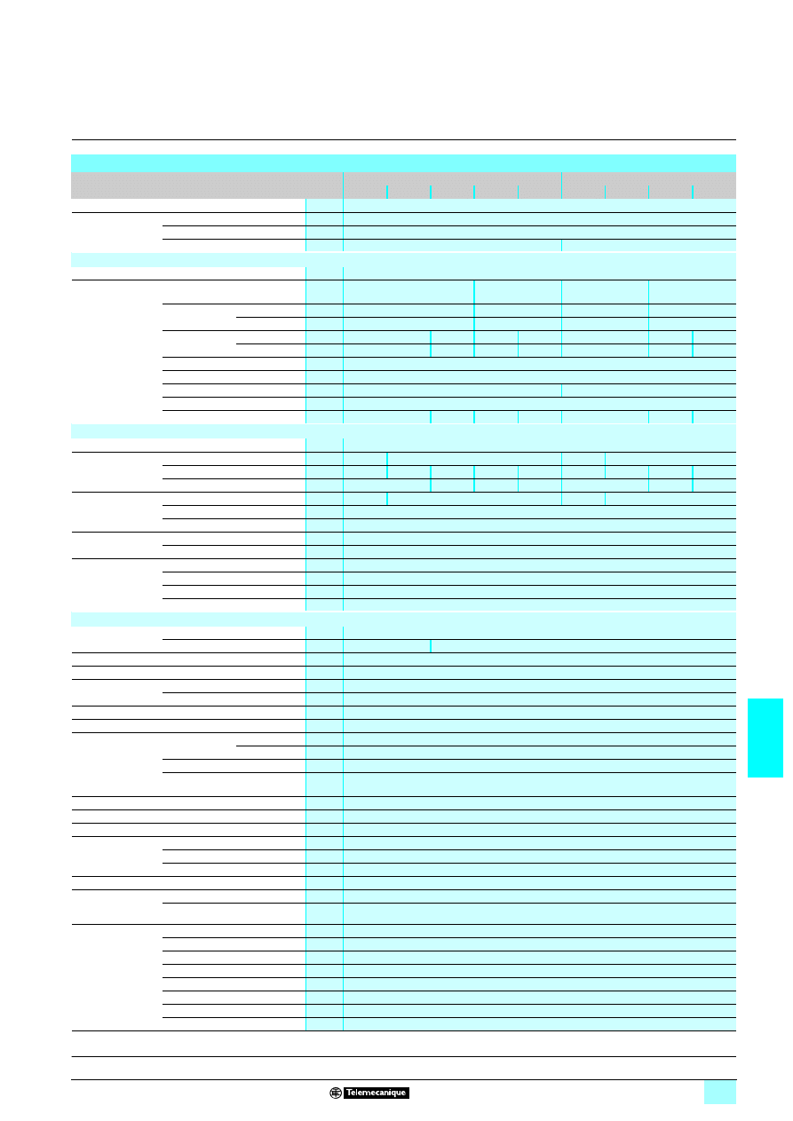
7/55
7
Characteristics
7
Power supplies and transformers
7
Power supplies for DC control circuits
Regulated switch mode power supplies
Phaseo Dedicated range
(1) Not indicated on the products.
Technical characteristics
Type of power supply
ABL 1REM
ABL 1RPM
12050
24025
24042
24062
24100
12083
24042
24062
24100
Product certifications/markings
UL 508, cCSAus, CSA 22.2 n° 60950-1, UL 60950-1, TÜV, CTick,
6
Conforming
to standards
Safety
IEC/EN 60950-1, SELV
Generic EMC
EN 50081-1, IEC 61000-6-2 (EN 50082-2), IEC/EN 61000-6-3
Low frequency harmonic currents
–
IEC/EN 61000-3-2
Input circuit
LED indication
–
Input voltages
Nominal voltage
V
100…240
1
100…120
1
200…240
1
100…240
1
100…120
1
200…240
1
Limit voltage
1
V
85…264
85…132/170…264
85…264
85…132/170…264
32compatible
V
120...370 (1)
180…370 (1)
120…370 (1)
180…370 (1)
Current
consumption
U
In
= 240 V
A
1
0.7
2.5
3
0.7
2.5
3
U
In
= 100 V
A
2
1.4
5
6
1.7
5
6
Permissable frequencies
Hz
47...63
Maximum inrush current
A
50
Power factor
0.65 approx.
0.7…0.95 approx. (depending on model)
Efficiency at nominal load
> 80 %
Dissipated power at nominal load
W
15
25
37.5
60
25
37.5
60
Output circuit
LED indicationL
Green LED
Nominal output
values
Voltage (U
Out
)
V
2
3
24
3
12
3
24
3
Current
A
5
2.5
4.2
6.2
10
8.3
4.2
6.2
10
Power
W
60
100
150
240
100
150
240
Precision
Ajustable output voltage
V
10.8…13.2 21.6…26.4
10.8…13.2 21.6…26.4
Line and load regulation
± 3 %
Residual ripple - noise
mV
< 200 (peak-peak)
Holding time
for I max.
U
In
= 240 V
ms
7 40
U
In
=100 V
ms
7 10
Protections
Against shorts-circuits
Permanent, automatic restart
Against overloads
1.1…1.5 In, see curve, page 7/57
Against undervoltages
U > 1.25 U
Out
Thermal
Yes (limiting operation above a temperature between 50 & 60 °C, depending on the load rating)
Operating and environmental characteristics
Connections
Input
mm
2
(2 + earth) x 4 (12 AWG)
Output
mm
2
2 x 4 (12 AWG)
4 x 4 (12 AWG)
Mounting
On panel or on ABL 1A01 reversible mounting bracket
Operating position
All positions with derating, see page 7/56
Connections
Series
Possible (2 max.), see page 7/57
Parallel
Possible (2 max.), see page 7/57
Degree of protection
IP 20, conforming to standard IEC/EN 60950 with clip-on cover over connection terminal block
Overvoltage category
II
Environment
Temperature
Operating
°C
0…+ 60 (derating from 45 °C), see page 7/56
Storage
- 25… + 85
Max. relative humidity
20…90 %
Vibrations,
according to EN 61131-2
5…9 Hz amplitude 3.5 mm and 9…150 Hz acceleration 2 g
Protection class
According to VDE 0106 1
Class 1
Degree of pollution
2
MTBF at 40 °C
> 100 000 h at 100 % load
Dielectric strength
50 and 60 Hz
for 1 min
Input/output
V rms
1 3000
Input/earth
V rms
1 1500
Output/earth
V rms
1 500
Input fuse incorporated
Yes (not interchangeable)
Emissions
according to
EN 61000-6-3
IEC/EN 61000-6-3 (generic)
Conducted/radiated
IEC/EN 55011, IEC/EN 55022 class B
Immunity
according to
EN 61000-6-2
IEC/EN 61000-6-2 (generic)
Electrostatic discharge
IEC/EN 61000-4-2 level 3 (4 kV contact/8 kV air)
Radiated electromagnetic fields
IEC/EN 61000-4-3 level 3 (10 V/m)
Induced electromagnetic fields
IEC/EN 61000-4-6 level 3 (10 V/m)
Rapid transients
IEC/EN 61000-4-4 level 3 (2 kV)
Surges
IEC/EN 61000-4-5
Conducted interference
IEC/EN 61000-4-8 level 4, IEC/EN 61000-4-12 level 3
Primary outage
Conforming to standard IEC/EN 61000-4-11(voltage dips and interrptions)
References:
page 7/58
Schemes:
page 7/58
Dimensions, mounting:
page 7/59
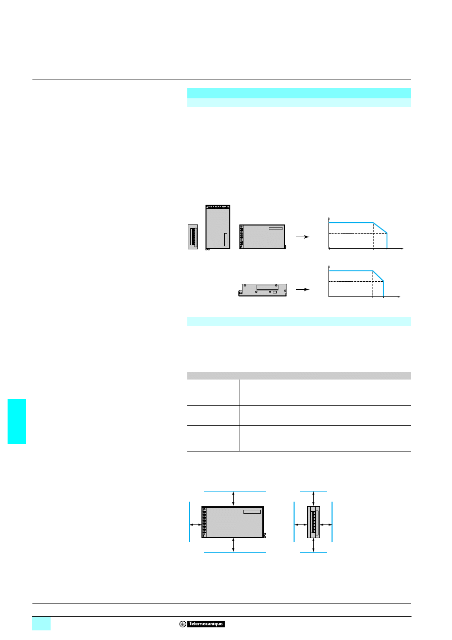
7/56
7
Characteristics
(continued)
7
Power supplies and transformers
7
Power supplies for DC control circuits
Regulated switch mode power supplies
Phaseo Dedicated range
The ambient temperature is a determining factor which limits the power that an
electronic power supply can deliver continuously. If the temperature around the
electronic components is too high, their life will be significantly reduced.
ABL 1R
7M24100 (240 W) power supplies are mechanically ventilated as from an
ambient temperature > 40 °C approx., or for a load rating > 90 % approx.
The rated ambient temperature for ABL 1REM/1RPM power supplies is + 50 °C.
Above this, derating is necessary up to a maximum temperature of + 60 °C.
The curves below show the power (in relation to the nominal power) which the power
supply can deliver continuously, according to the ambient temperature.
Derating should be considered in extreme operating conditions:
23intensive operation (output current permanently close to the nominal current,
combined with a high ambient temperature),
23output voltage set above 24 V (to compensate for line voltage drops, for example),
23parallel connection to increase the total power.
In all cases, there must be adequate convection round the products to ensure easier
cooling. There must be a clear space of 50 mm (1.97 inch) above and below the
power supplies, and of 20 mm (0.79 inch) at the sides.
Output characteristics
Derating
Tp (˚C/˚F)
Tp (˚C/˚F)
50˚C/
122˚F
60˚C/
140˚F
0˚C/
32˚F
0˚C/
32˚F
P/P
N
100 %
60 %
P/P
N
100 %
60 %
45˚C/
113˚F
55˚C/
131˚F
Mountig on vertical plane
Montage on horizontal plane
Extreme operating conditions
General rules to be complied with
Intensive operation
See derating on above curves.
Example for ABL 1 mounted vertically:
- without derating, from 0 °C to 50 °C,
- derating of nominal current by 4 %, per additional °C, up to 60 °C.
Rise in
output voltage
The nominal power is fixed.
Increasing the output voltage means that the current delivered must be
reduced.
Parallel connection
to increase
the power
The total power is equal to the sum of the power supplies used, but the
maximum ambient temperature for operation is 50 °C.
To improve heat dissipation, the power supplies must not be in contact
with each other.
1
(0.59)
50
(1.97)
50
(1.97)
50
(1.97)
50
(1.97)
20
(0.79)
20
(0.79)
Dimensions are in
mm (inch)
Presentation:
page 7/54
Description:
page 7/54
References:
page 7/58
Schemes:
page 7/58
Dimensions, mounting:
page 7/59
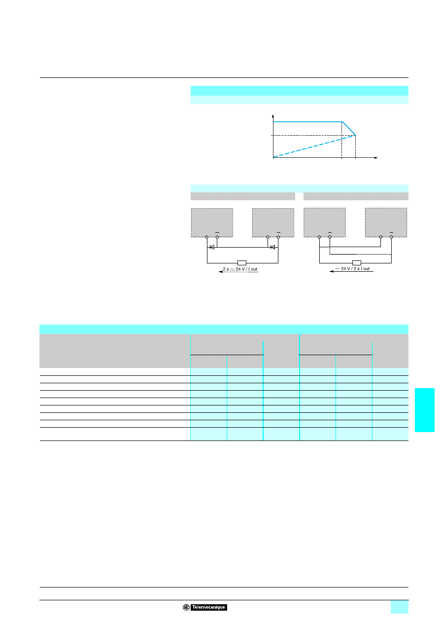
7/57
7
Characteristics
(continued),
selection of protection
7
Power supplies and transformers
7
Power supplies for DC control circuits
Regulated switch mode power supplies
Phaseo Dedicated range
(1) Pending UL certification.
Output characteristics
(continued)
Load limits
0
In
x
1,1 In
≤ x ≤ 1,5 In
U out
I out
24 V
15 V
Series or parallel connection
Series connection
Parallel connection
(1) 8 A/100 V Shottky diode for ABL 1REM12050/1REM24025/1R
5M24042.
15 A/100 V Shottky diode for ABL 1RPM12083/1R
5M24062/1R5M24100.
+
+
ABL 1
ABL 1
(1)
(1)
+
+
ABL 1
ABL 1
Selection of protection for the power supply primary
Type of mains supply
2
2
2
2 115 V single-phase
2
2
2
2 230 V single-phase
Type of protection (2 poles protected)
Thermal-magnetic
circuit-breaker
gG fuse
Thermal-magnetic
circuit-breaker
gG fuse
GB2 (IEC) (1) C60N (IEC)
C60N (UL)
GB2 (IEC) (1)
C60N (IEC)
C60N (UL)
ABL 1REM12050
GB2 DB07
24517
2 A
GB2 DB07
24517
2 A
ABL 1REM24025
GB2 DB07
24517
2 A
GB2 DB07
24517
2 A
ABL 1RPM12083
GB2 DB07
24517
2 A
GB2 DB07
24517
2 A
ABL 1REM24042
GB2 DB07
24517
2 A
GB2 DB07
24517
2 A
ABL 1RPM24042
GB2 DB07
24517
2 A
GB2 DB07
24517
2 A
ABL 1REM24062
GB2 DB07
24517
2 A
GB2 DB08
24518
4 A
ABL 1RPM24062
GB2 DB07
24517
2 A
GB2 DB08
24518
4 A
ABL 1REM24100
GB2 DB08
24518
4 A
GB2 DB10
17454
6 A
ABL 1RPM24100
GB2 DB08
24518
4 A
GB2 DB10
17454
6 A
Presentation:
page 7/54
Description:
page 7/54
References:
page 7/58
Schemes:
page 7/58
Dimensions, mounting:
page 7/59
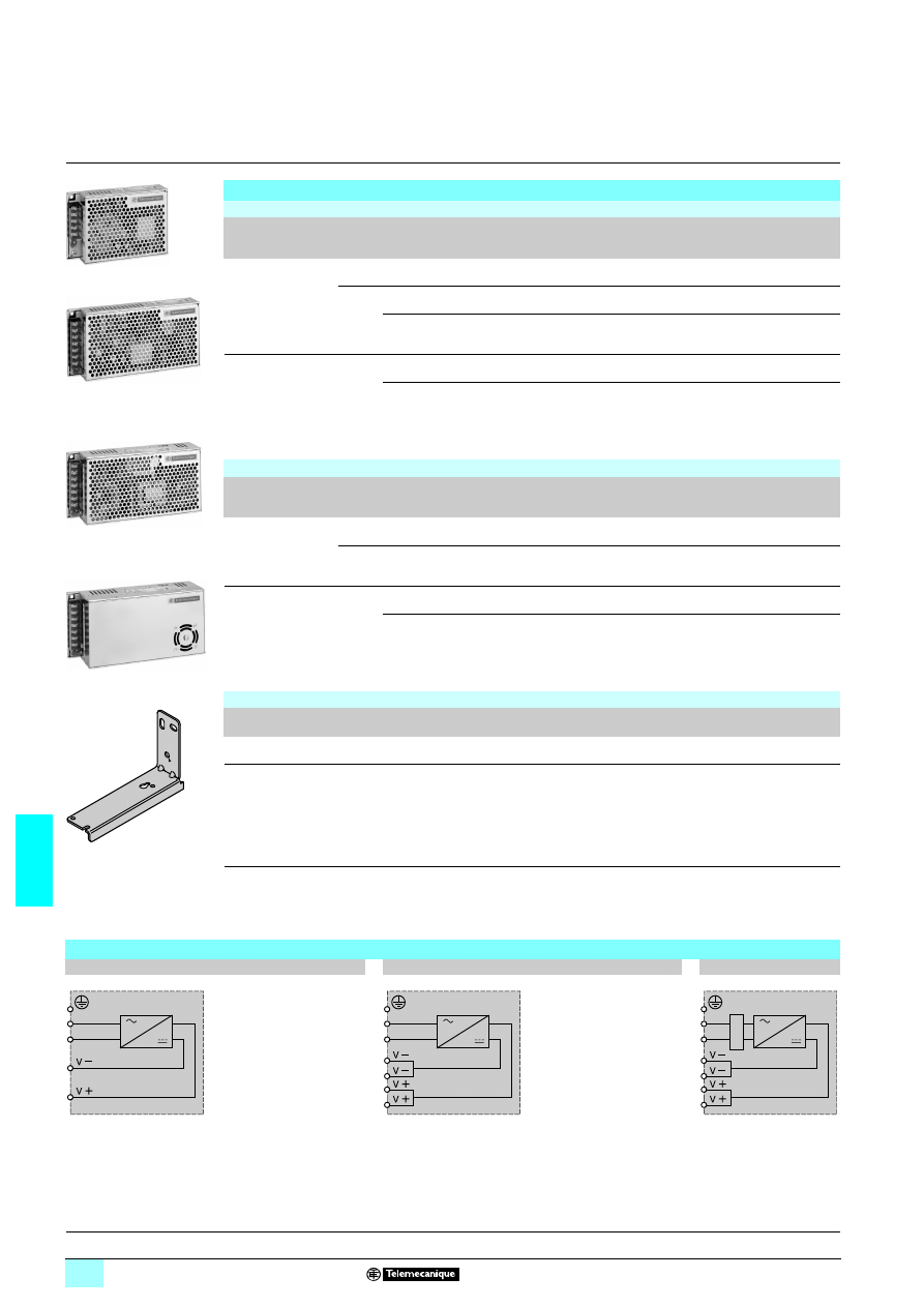
7/58
7
References,
schemes
7
Power supplies and transformers
7
Power supplies for DC control circuits
Regulated switch mode power supplies
Phaseo Dedicated range
(1) Compatible input voltage
1 120…370 V not indicated on the product.
(2) Compatible input voltage
1 180…370 V not indicated on the product.
References
Regulated switch mode power supplies: ABL 1REM Phaseo Dedicated range
Input voltage
47…63 Hz
Output
voltage
Nominal
power
Nominal
current
Auto-protect
reset
Conforming
to standard
IEC/EN 61000-3-2
Reference
Weight
100…240 V
2
2
2
2 (1)
single-phase
wide range
12 V
5
5
5
5 60 W
5 A
Automatic
No
ABL 1REM12050
0.440
24 V
5
5
5
5 60 W
2.5 A
Automatic
No
ABL 1REM24025
0.440
100 W
4.2 A
Automatic
No
ABL 1REM24042
0.640
100...120 V
2
2
2
2
200...240 V
2
2
2
2
(2) single-phase
24 V
5
5
5
5 150 W
6.2 A
Automatic
No
ABL 1REM24062
0.730
240 W
10 A
Automatic
No
ABL 1REM24100
0.880
Regulated switch mode power supplies: ABL 1RPM Phaseo Dedicated range
Input voltage
47…63 Hz
Output
voltage
Nominal
power
Nominal
current
Auto-protect
reset
Conforming
to standard
IEC/EN 61000-3-2
Reference
Weight
100…240 V
2
2
2
2 (1)
single-phase
wide range
12 V
5
5
5
5 100 W
8.3 A
Automatic
Yes
ABL 1RPM12083
0.640
24 V
5
5
5
5 100 W
4.2 A
Automatic
Yes
ABL 1RPM24042
0.640
100...120 V
2
2
2
2
200...240 V
2
2
2
2
(2) single-phase
24 V
5
5
5
5 150 W
6.2 A
Automatic
Yes
ABL 1RPM24062
0.970
240 W
10 A
Automatic
Yes
ABL 1RPM24100
1.230
Mouting accessories
Description
For power supplies
Sold in
lots of
Unit
reference
Weight
kg
Reversible mounting bracket For the mounting on the back of cabinet of
ABL 1R
5M55555 power supply
5
ABL 1A01
0.085
Clip-on mounting plate
for
4 35 mm mounting rail
- ABL 1REM12050/24025: the plate mounting
on
4 requires one mounting plate
- ABL 1RPM12083 and
ABL 1R
5M24042/24062/24100: the plate
mouting on
4 requires 2 mounting plates
- ABL 1R
5M55555: the mounting on the back
of cabinet on the
4 rail requires one
mounting plate
5
ABL 1A02
0.035
10
97
10
ABL 1REM24025
10
97
11
ABL 1R
4M24042
10
971
2
ABL 1R
4M24062
10
97
13
ABL 1R
4M24100
ABL 1A01
Schemes
ABL 1REM12050, 1REM24025
ABL 1REM24042, 1REM24062, 1REM24100
ABL 1RPM
11111
11111
11111
11111
N
L
N
L
N
L
F
iltr
e
Presentation:
page 7/54
Description:
page 7/54
Characteristics:
pages 7/55 to 7/57
Dimensions, mounting:
page 7/59
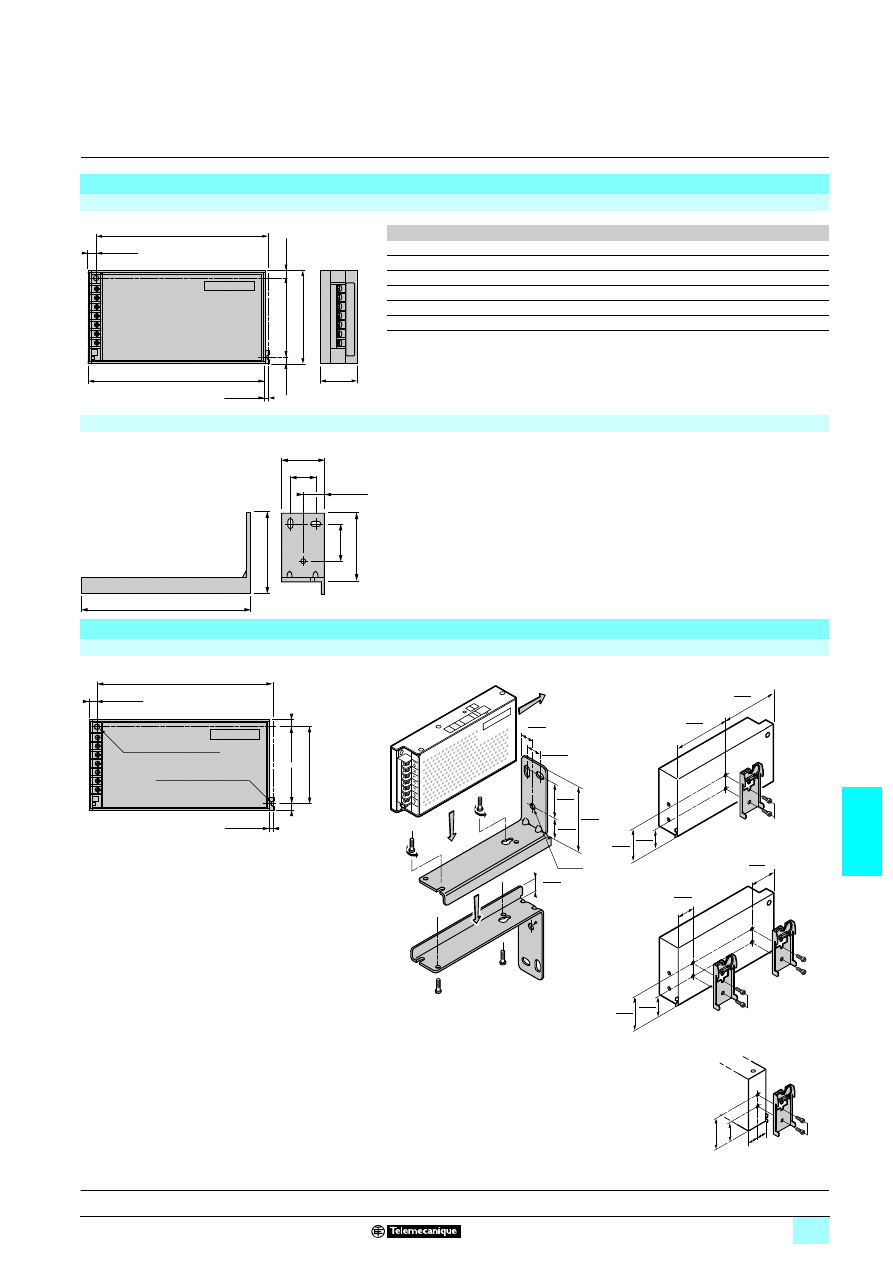
7/59
7
Dimensions,
mounting
7
Power supplies and transformers
7
Power supplies for DC control circuits
Regulated switch mode power supplies
Phaseo Dedicated range
Dimensions
(the dimensions are in mm/inch)
ABL 1R
1111M11111
11111
11111
11111
ABL
L
P
a
b
c
1REM12050
150/5.91
38/1.5
144/5.67
38/1.5
58/2.28
1REM24025
150/5.91
38/1.5
144/5.67
38/1.5
58/2.28
1REM12083
200/7.87
38/1.5
194/7.64
38/1.5
58/2.28
1RPM24042
200/7.87
38/1.5
194/7.64
38/1.5
58/2.28
1RPM24062
200/7.87
50/1.97
194/7.64
28/1.10
48/1.89
1RPM24100
200/7.87
65/2.56
194/7.64
28/1.10
48/1.89
ABL 1A01
Mounting
ABL 1R
1111M11111
11111
11111
11111
Direct mounting by 2 M4 x 20 screws
Mounting on the back on ABL 1A01
reversible bracket by 3
∅ 4 mm screws
Mounting on ABL 1A02 clip-on mounting on
6
6
6
6 35 mm rail
P
2,5/0.10
8,5/0.33
8/0.31
L
a
8/0.31
98/3.86
82/3.23
36/1.42
22/0.87
65/2.56
116/4.57
36/1.42
55/2.17
18/0.71
2,5/0.10
8,5/0.33
M4 x 20/# 8 x 32 (A)
M4 x 20/# 8 x 32 (B)
8/0.31
a
8/0.31
82/3.23
36
1.42
11,5
0.45
18
0.71
22,25
0.88
55
2.17
M4x8
M4x8
3x 4
M4x8
M4x8
10
0.39
59
2.32
20
0.79
30
1.18
39
1.54
58
2.28
75
2.95
75
2.95
38
1.49
M4x8
M4x8
M4x8
"
"
c b
ABL 1REM12050
ABL 1REM24025
ABL 1RPM12083
ABL 1R
5M24042/062/100
Mounting by the back
ABL 1R
5M55555 :
Presentation:
page 7/54
Characteristics:
pages 7/55 to 7/57
References :
page 7/58
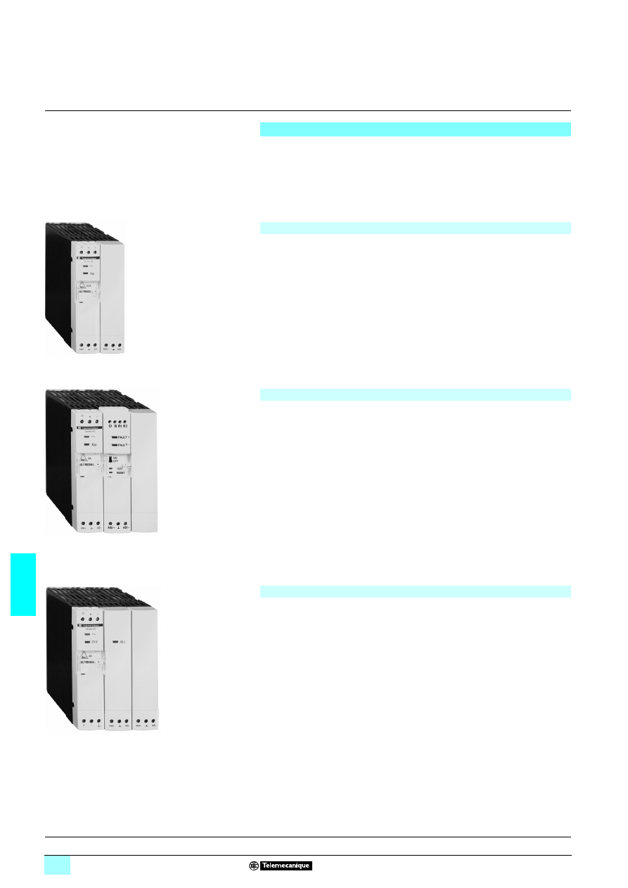
7/60
7
Presentation
7
Power supplies and transformers
7
Power supplies for control circuits for
AS-Interface cabling system
Regulated switch mode power supplies
Phaseo AS-Interface range
Consistent with the standard Phaseo line, the range of ASI ABL power supplies is
designed to deliver a d.c. voltage, as required by AS-Interface cabling systems.
Three versions are available to meet all needs encountered in industrial applications,
in enclosures, cells or floor-standing enclosures. These single-phase, electronic,
switch mode power supplies guarantee the quality of the output current, in
accordance with the electrical characteristics and conforming to standard EN 50295.
Operating on a 100 to 240 V a.c. supply, this power supply delivers a voltage of
30 V d.c. Available in 2.4 and 4.8 A ratings, the outgoing terminal block allows the
cable to be connected separately to the
AS-Interface interface modules and to the AS-Interface master. Input and output
LEDs allow fast and continuous diagnostics.
Operating on a 100 to 240 V a.c. supply, this power supply delivers a voltage of
30 V d.c. Available in 2.4 and 4.8 A ratings, it allows diagnosis and management of
earth faults on AS-Interface interface modules. In the event of an earth fault, the
Phaseo power supply stops dialogue on the AS-Interface cabling system and puts
the installation in a fallback condition. Restarting is only possible after deliberate
acknowledgement of the fault. Two inputs/outputs enable dialogue with a processing
unit. The outgoing terminal block is used to connect the AS-Interface cable
separately to the interface modules and master modules. Input, output and earth fault
LED’s allow fast and continuous diagnostics.
2
Warning:
1 The earth (GND) (1) connection must be made. In the event of disconnection, the
built-in detector becomes inoperative. To obtain earth connection diagnostics, it is
recommended that an ASI ABLB300
7 power supply be used together with insulation
relay RMO PAS 101.
Operating on a 100 to 240 V a.c. supply, this product provides two separate power
supplies, which are totally independent in the way they operate.
Two output voltages - 30 V/2.4 A (AS-Interface line supply) and 24 V/3 A - are
available, so making it possible to supply the control equipment without an additional
power supply. Input and output LEDs allow fast and continuous diagnostics.
(1) Compulsory connection.
Power supplies for AS-Interface cabling system
ASI ABLB300
7
ASI ABLB3002
ASI ABLD300
73
ASI ABLD3004
ASI ABLM3024
ASI ABLM3024
Characteristics :
page 7/61
References :
page 7/63
Dimensions :
page 7/63
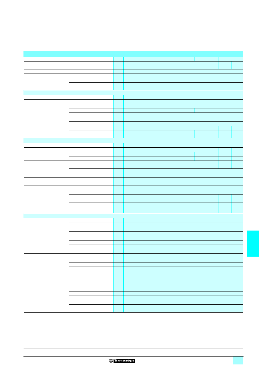
7/61
7
Characteristics
7
Power supplies and transformers
7
Power supplies for control circuits for
AS-Interface cabling system
Regulated switch mode power supplies
Phaseo AS-Interface range
Technical characteristics
Type of power supply
ASI ABLB3002
ASI ABLB3004
ASI ABLD3002
ASI ABLD3004
ASI ABLM3024
Functions
Supply to the AS-Interface line (30 V
3)
30 V
3
supply
24 V
3
supply
Product certifications
UL 508, CSA 22-2 n° 950, TÜV 60950-1
Conforming to standards
Safety
EN 60950-1
EMC
EN 50081-1, IEC 61000-6-2, EN 55022 class B
Low frequency
harmonic currents
No
Input circuit
LED indication
Orange LED
Input voltage
Rated values
V
1 100…240
Permissible values
V
1 85…264
Current consumption
A
0.5
1
0.5
1
Permissible frequencies
Hz
47…63
Current at switch-on
A
< 30
Power factor
0.65
Efficiency at nominal load
%
> 83
> 83
> 80
Dissipated power at nominal
load
W
14.7
29.5
14.7
29.5
14.7
36
Output circuit
LED indication
Green LED
Nominal output values
Voltage (U
out
)
V
30 (AS-Interface)
3 30
3 24
Current
A
2.4
4.8
2.4
4.8
2.4
3
Power
W
72
144
72
144
72
72
Precision
Adjustable output voltage
V
–
–
100 to
120 %
Line and load regulation
3 %
Residual ripple - noise
mV
300 - 50
Holding time
for I max
U
in
min
ms
7 10
Protection
Against short-circuit
Permanent. Automatic restart after elimination of the fault
Against overload
1.1 In
Against overvoltage
Tripping if U > 1.2 Un
U >
1.2 Un
U >
1.5 Un
Against undervoltage
Tripping if U < 0.95 Un
U <
0.95 Un
U <
0.8 Un
Operating characteristics
Connections
Input
mm
2
2 x 2.5 screw terminals + earth
Output
mm
2
2 x 2.5 screw terminals + earth, multiple output
Environment
Operating temperature
°C
0 to + 60 (derating from 50, see page 7/62)
Storage temperature
°C
- 25 to + 70
Maximum relative humidity
95 % (without condensation or dripping water)
Degree of protection
IP 20 (conforming to IEC 529)
Vibrations
EN 61131-2
Operating position
Vertical
MTBF
h
> 100000 (conforming to Bell core, at 40 °C)
Dielectric strength 50 Hz
during 1 min
Input/output
V rms 3000
Input/earth
V rms 3000
Output/earth (and output/output) V rms 500
Input fuse incorporated
Yes (not interchangeable)
Emission
according to EN 61000-6-3
Conducted/radiated
Class B (conforming to EN 55022)
Immunity
according to EN 61000-6-2
Electrostatic discharge
EN 61000-4-2 (4 kV contact/8 kV air)
Radiated lectromagnetic field
EN 61000-4-3 level 3 (10 V/m)
Induced electromagnetic field
EN 61000-4-6 (10 V/m)
Rapid transients
EN 61000-4-4 level 3 (2 kV),
Primary outages
EN 61000-4-11 (voltage dips and interruptions)
Presentation :
page 7/60
References :
page 7/63
Dimensions :
page 7/63
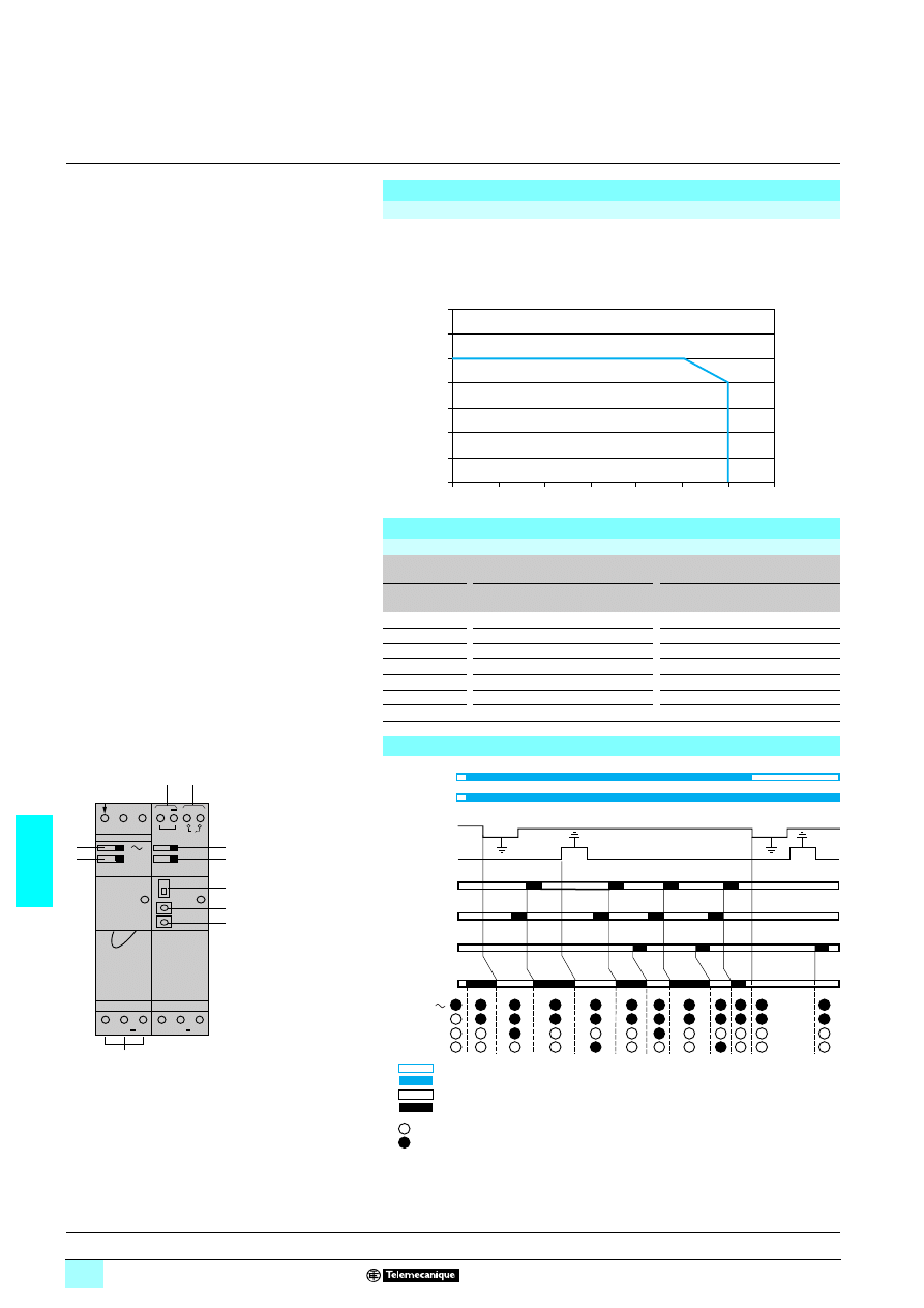
7/62
7
Characteristics,
selection
7
Power supplies and transformers
7
Power supplies for control circuits for
AS-Interface cabling system
Regulated switch mode power supplies
Phaseo AS-Interface range
The ambient temperature is a determining factor which limits the power that an
electronic power supply can deliver continuously. If the temperature around the
electronic components is too high, their life will be significantly reduced.
The graph below shows the power (in relation to the nominal power) which the power
supply can deliver continuously, according to the ambient temperature.
Output characteristics
Derating
0
0
10
20
30
40
50
60
70
20
40
60
80
100
120
140
P/Pn (%)
Maximum operating temperature (°C)
Presentation :
page 7/60
Characteristics :
page 7/61
References :
page 7/63
Dimensions :
page 7/63
Selection
Upstream protection of power supplies for AS-Interface cabling system
Type of
mains supply
2
2
2
2 115 V single-phase
2
2
2
2 230 V single-phase
Type of
protection
Thermal-magnetic
circuit-breaker
Gg
fuse
Thermal-magnetic
circuit-breaker
Gg
fuse
Single-pole
GB2 CB
55
2-pole
GB2 DB
55 C60N
GB2 DB
55 C60N
ASI ABLB3002
GB2
5B07 MG24517 (1) 2 A
GB2 DB06
MG24516 (1)
2 A
ASI ABLB3004
GB2
5B08 MG24518 (1) 4 A
GB2 DB07
MG17453 (1)
2 A
ASI ABLD3002
GB2
5B07 MG24517 (1) 2 A
GB2 DB06
MG24516 (1)
2 A
ASI ABLD3004
GB2
5B08 MG24518 (1) 4 A
GB2 DB07
MG17453 (1)
2 A
ASI ABLM3024
GB2
5B07 MG24517 (1) 2 A
GB2 DB06
MG17453 (1)
2 A
(1) UL certified circuit-breaker.
Function diagram
(1) 30 ms min.
(2) 15 ms.
(3) 20 ms.
(4) Warning: the earth fault detector will only operate if the earth (GND) terminal is connected.
N
L
24 V
AS-i : 2,4 A
AS-i + AS-i GND
AS-i + AS-i GND
+
1
2
10
6
7
8
9
5
1
4
3
2
(1)
(1)
(3)
(3)
(3)
(3)
(2)
(2)
(2)
(2)
ON/OFF DDT
AS-i +
AS-i –
Reset
(1)
Reset
Test
Fault
Fault –
Fault +
AS-i
1
2
3
or
10
4
5
6
7
8
9
Supply
OFF
ON
Input at state 0 or contact open
Input at state 1 or contact closed
LED off
LED on
AS-i + AS-i
–
, and GND (4)
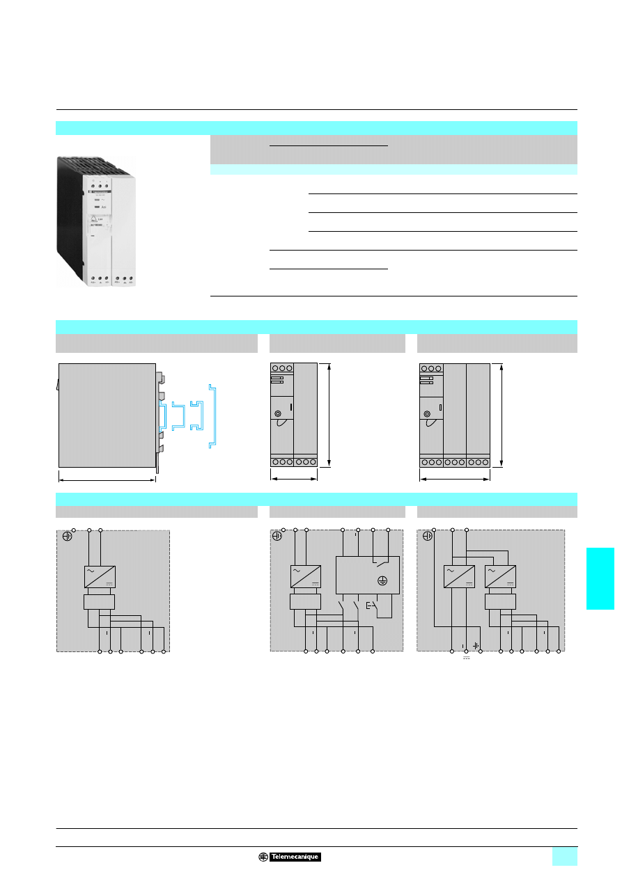
7/63
7
References,
dimensions,
schemes
7
Power supplies and transformers
7
Power supplies for control circuits for
AS-Interface cabling system
Regulated switch mode power supplies
Phaseo AS-Interface range
Phaseo AS-Interface range regulated switch mode power supplies
Input voltage
Secondary
Auto-protect
reset
Earth fault
detection
Reference
Weight
kg
Output
voltage
Nominal
power
Nominal
current
Single phase (N-L1) or 2-phase (L1-L2)
2
2
2
2 100…240 V
- 15 %, + 10 %
50/60 Hz
3 30 V
72 W
2,4 A
Auto
No
ASI ABLB3002
0.800
144 W
4,8 A
Auto
No
ASI ABLB3004
1.300
72 W
2,4 A
Auto
Yes
ASI ABLD3002
0.800
144 W
4,8 A
Auto
Yes
ASI ABLD3004
1.300
3 30 V 72 W
2,4 A
Auto
No
ASI ABLM3024
1.300
3 24 V
72 W
3 A
Dimensions
Common side view
Mounting on
4 35 et 75 mm rail
ASI ABLB3002
ASI ABLD3002
ASI ABLB3004 / ABLD3004
ASI ABLM3024
ASI ABL
53002
120
54
120
81
120
Schemes
ASI ABLB300
1111
ASI ABLD300
1111
ASI ABLM3024
AS-i
AS-i +
AS-i
AS-i +
L
N
GND
GND
Filter
AS-i
AS-i +
AS-i
GND
GND
AS-i +
L
1
2
N
ON/
OFF
Set
+
Filter
Fault
detector
AS-i
AS-i +
AS-i
AS-i +
L
N
+
24 V
GND
GND
Filter
Presentation :
page 7/60
Characteristics :
page 7/61
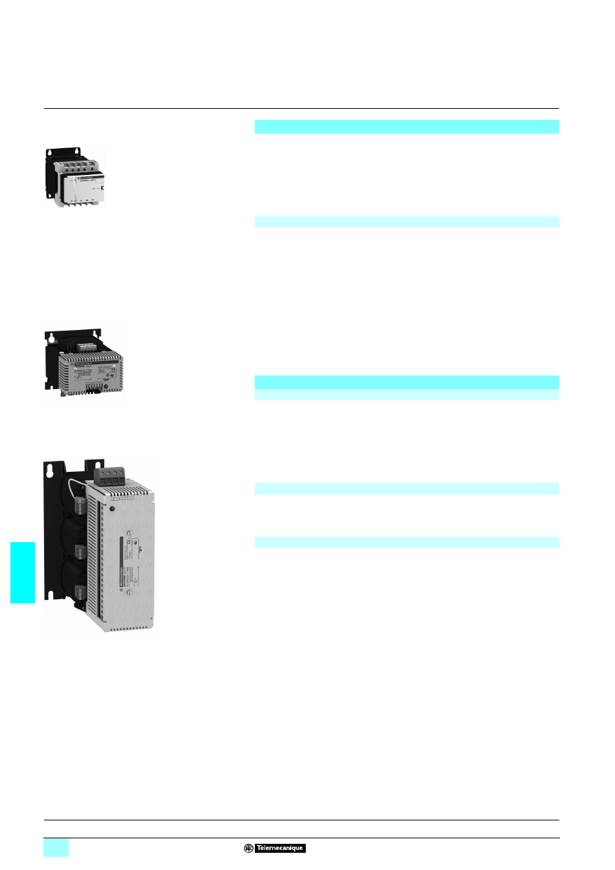
7/64
7
Presentation
7
Power supplies and transformers
7
Power supplies for DC control circuits
Rectified and filtered power supplies
Phaseo Rectified range
The ABL 8FEQ/TEQ range of power supplies is designed to provide the DC voltage
necessary for the control circuits of automation system equipment. Comprising two
families, this range meets all the needs encountered in industrial, commercial and
residential applications. With phase-to-neutral or three-phase connection, of the
conventional type with rectifier, they provide a quality of output current that is suitable
for the loads supplied and compatible with the line supply available in the equipment.
Clear guidelines are given for selecting protection devices which are often used with
them, and thus a comprehensive solution is provided that can be used in total safety.
Filtered rectified power supplies are built using a safety transformer equipped with a
bridge rectifier and smoothing capacitors.
With no regulation system, and of simple and rugged construction, their output
voltage will withstand line voltage variations and load variations while remaining
within the range defined in standards IEC 1131-2.
These power supplies are split into two families:
1 The ABL 8FEQ family, with phase-to-neutral or phase-to-phase connection,
rectified and filtered, enables connection to European 230/400 V line supplies. Power
supplies from 0.5 A to 4 A are available for direct mounting on a
3 rail.
1 The ABL 8TEQ family, with three-phase connection, filtered and rectified, is
particularly suitable where a high power level is required for controlling actuators and
preactuators. This is especially true for "All 24 V
4" equipment, or for pilot operation
of DC valves and solenoid valves.
Rectified power supplies provide a non-regulated voltage, sensitive to load and line
supply fluctuations. They can only be used on good-quality line supplies, with
fluctuations limited to -10%… + 10% of the nominal value.
Graphs showing the output voltage as a function of the current, the load and the input
voltage for ABL 8FEQ and ABL 8TEQ supplies are given on pages 7/67 and 7/68.
If the quality of the line supply is not suitable for a rectified power supply, a regulated
supply must be used.
By design, ABL 8FEQ and ABL 8TEQ rectified power supplies consume very little
harmonic current; they meet the requirements of standard EN 61000-3-2 and can
therefore be connected directly to public distribution systems.
In the event of an overload or short-circuit, rectified power supplies must be protected by
a downstream fuse or circuit-breaker to prevent their destruction. ABL 8FEQ models up
to 6 A are fitted with a 5 x 20 mm glass fuse and do not need any external downstream
protection.
ABL 8FEQ/8TEQ power supplies
ABL 8FEQ24
550
Filtered rectified power supplies
ABL 8TEQ
Selection of power supplies
Quality of the line supply
Harmonic pollution (power factor)
Behavior in the event of short-circuits
Characteristics:
pages 7/65 to 7/68
References:
page 7/70
Dimensions:
page 7/71
Schemes:
page 7/71
ABL 8FEQ24040
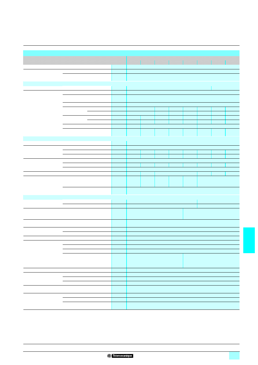
7/65
7
Characteristics
7
Power supplies and transformers
7
Power supplies for DC control circuits
Rectified and filtered power supplies
Phaseo Rectified range
Technical characteristics
Type of power supply
ABL 8FEQ
24005
24010
24020
24040
24060
24100
24150
24200
Certifications
cULus, ENEC
Conformity to standards
Safety
IEC 61558-2-6, EN 61558-2-6, UL 60950-1, UL 508
EMC
EN 62041, EN 61000-3-2
Input circuit
LED indication
Voltage LED (orange)
–
Input values
Nominal voltage
V
230 or 400 V
12phase-to-neutral or phase-to-phase with - 15 V and + 15 V connectors
Limit voltage
V
207...253 V
12
360...440 V
12
Permissible frequencies
Hz
47…63
Maximum inrush
current
230 V
1
A
1.68
4.8
9
10
16
27.8
31.9
400 V
1
A
0.97
2.77
5.2
5.78
9.24
16
18.4
Power factor
230 V
1
0.656
0.764
0.737
0.689
0.781
0.783
0.693
0.698
400 V
1
0.881
0.905
0.863
0.867
0.860
0.834
0.663
0.671
Efficiency at nominal load
%
71
75
80
Dissipated power at nominal load
W
3.48
6
12
24
36
48
72
96
Output circuit
Diagnostics
Voltage LED (green)
Nominal values
Voltage
V
24 V
3
Current
A
0.5
1
2
4
6
10
15
20
Power
W
12
24
48
96
144
240
360
480
Limit values
Output voltage
See graphs on pages 7/67 and 7/68
Voltage variation at nominal load
%
10...16
18...25
14...21
13...20
15...21
14...21
12...16
12...15
Residual ripple - noise
≤ 5 %
Holding time
at 400 V
12
ms
17
15
14
15
14
10
Protection
Against overloads and short-circuits
Fuse
5 x 20
0.5 AT
Fuse
5 x 20
1 AT
Fuse
5 x 20
2 AT
Fuse
5 x 20
4 AT
Fuse
5 x 20
6.3 AT
External, depending on the
output current
Against overvoltages
2 J peak limiter
Operating and environmental characteristics
Connections
Input
mm
2
2 x 2.5...4 (AWG 14/11) + Ground
2 x 2.5 (AWG 14) + Ground
Output
mm
2
2 x 2.5...4 (AWG 14/11) + Ground
2 x 4 (AWG 11) + Ground
Mounting
On
6
rail, 35 x 7.5 mm and
35 x 15 mm or via 4 screws (not
supplied)
4 screws (not supplied)
Operating position
Vertical: 60°C
Horizontal: 40°C
Connections
Series
Possible
Parallel
Possible
Degree of protection
IP 20 conforming to IEC 60529
Environment
Operating temperature
°C
- 20…+ 60
Storage temperature
°C
- 40…+ 80
Maximum relative humidity
95% without condensation or dripping water
Vibration acc. to IEC 60068-1 (ability
to stay attached to the rail)
3...13.9 Hz amplitude 1 mm and
13.9...47 Hz acceleration 0.7 g
47...57 Hz amplitude 0.05 mm and
57...150 Hz acceleration 1 g
–
Protection class according to VDE 0106 1
Class I
Dielectric strength
50 Hz for 1 min
Input/output
V rms
4600
1
Input/ground
V rms
2000
1
Output/ground
V rms
500
1
Emissions
according to EN 61000-6-3
Conducted/radiated
EN 55011 Class B
Immunity
according to EN 61000-6-2
Electrostatic discharge
EN 61000-4-2 (4 kV contact and 8 kV air)
Rapid transients
EN 61000-4-4 (2 kV)
Surges
EN 61000-4-5 (2 kV)
Presentation :
page 7/64
References:
page 7/70
Dimensions:
page 7/71
Schemes:
page 7/71
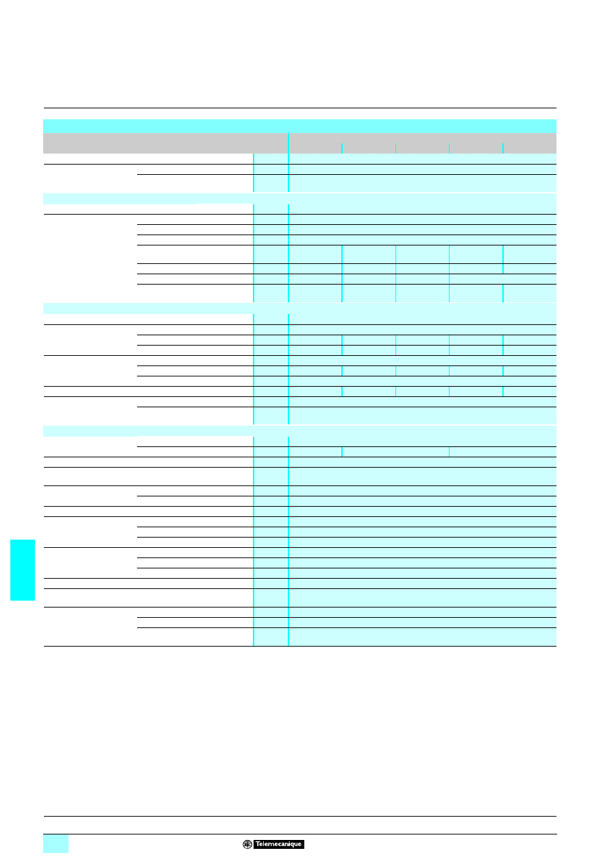
7/66
7
Characteristics
(continued)
7
Power supplies and transformers
7
Power supplies for DC control circuits
Rectified and filtered power supplies
Phaseo Rectified range
Technical characteristics
Type of power supply
ABL 8TEQ
24100
24200
24300
24400
24600
Certifications
cULus, ENEC
Conformity to standards
Safety
IEC 61558-2-6, EN 61558-2-6, UL 60950-1, UL 508
EMC
EN 62041, EN 61000-3-2
Input circuit
LED indication
–
Input values
Nominal voltage
V
400 V
12on three phases with - 20 V and + 20 V connectors
Limit voltage
V
360...440 V
1
Permissible frequencies
Hz
47…63
Maximum inrush
current
400 V
1
A
7
14
20
30
41
Power factor
400 V
1
4
0.872
0.81
0.835
0.857
0.757
Efficiency at nominal load
%
73
78
77
78
Dissipated power at nominal load
W
64
105
165
211
316
Output circuit
Diagnostics
Voltage LED (green)
Nominal values
Voltage
V
24 V
3
Current
A
10
20
30
40
60
Power
W
240
480
720
960
1440
Limit values
Output voltage
See graphs on pages 7/67 and7/68
Voltage variation at nominal load
%
17.08
14.25
18.67
14.58
15.29
Residual ripple - noise
≤ 2 %
Holding time
at 400 V
12
ms
4
6
7
5
4
Protection
Against overloads and short-circuits
External, depending on the output current
Against overvoltages
2 J peak limiter
Operating and environmental characteristics
Connections
Input
mm
2
2 x 2.5...4 (AWG 14/11) + Ground
Output
mm
2
2 x 4 (AWG 11) 2 x 10...16 (AWG 8/6)
2 x 16 (AWG 6)
Mounting
4 screws (not supplied)
Operating position
Vertical: 55°C
Horizontal: 40°C
Connections
Series
Possible
Parallel
Possible
Degree of protection
IP 20 conforming to IEC 60529
Environment
Operating temperature
°C
- 20…+ 55
Storage temperature
°C
- 40…+ 80
Maximum relative humidity
95% without condensation or dripping water
Dielectric strength
50 Hz for 1 min
Input/output
V rms
4600
1
Input/ground
V rms
2000
1
Output/ground
V rms
500
1
Protection class according to VDE 0106 1
Class I
Emissions
according to EN 61000-6-3
Conducted/radiated
EN 55011 Class B
Immunity
according to EN 61000-6-2
Electrostatic discharge
EN 61000-4-2 (4 kV contact and 8 kV air)
Rapid transients
EN 61000-4-4 (2 kV)
Surges
EN 61000-4-5 (2 kV)
Presentation :
page 7/64
References:
page 7/70
Dimensions:
page 7/71
Schemes:
page 7/71
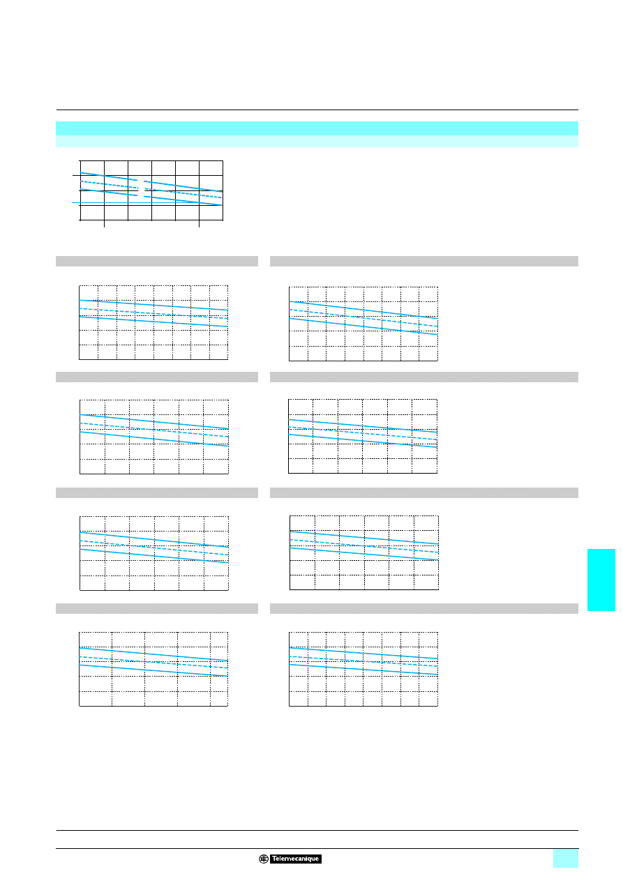
7/67
7
Output characteristics
7
Power supplies and transformers
7
Power supplies for DC control circuits
Rectified and filtered power supplies
Phaseo Rectified range
Output characteristics
Example of how to use the graph
Nominal load current (at 24 V
1)
For an ABL 8FEQ power supply, used with a variable load of 1 to 5 A, on a line supply Un ±10%,
the graph gives the limits at the load terminals: 21 and 30 V.
Note: The load lines are represented by vertical lines, images of the nominal current for the load
supplied at its nominal voltage.
1
Nominal line supply +10%
2
Nominal line supply
3
Nominal line supply -10%
ABL 8FEQ24005
ABL 8FEQ24010
ABL 8FEQ24020
ABL 8FEQ24040
ABL 8FEQ24060
ABL 8FEQ24100
ABL 8FEQ24150
ABL 8FEQ24200
15 V
0 A
1 A
2 A
3 A
4 A
5 A
6 A
25 V
30 V
21 V
35 V
1
2
3
10 V
15 V
20 V
25 V
30 V
35 V
0,25 A
0,50 A
0,75 A
10 V
15 V
20 V
25 V
30 V
35 V
0,75 A
1,5 A
0 A
10 V
15 V
20 V
25 V
30 V
35 V
0 A
1 A
2 A
3 A
10 V
15 V
20 V
25 V
30 V
35 V
0 A
6 A
2 A
4 A
1 A
3 A
5 A
10 V
15 V
20 V
25 V
30 V
35 V
9 A
0 A
6 A
3 A
10 V
15 V
20 V
25 V
30 V
35 V
0 A
15 A
5 A
10 A
10 V
15 V
20 V
25 V
30 V
35 V
22,5 A
20 A
10 A
15 A
5 A
0 A
10 V
15 V
20 V
25 V
30 V
35 V
30 A
15 A
0 A
Presentation:
page 7/64
References:
page 7/70
Dimensions:
page 7/71
Schemes:
page 7/71
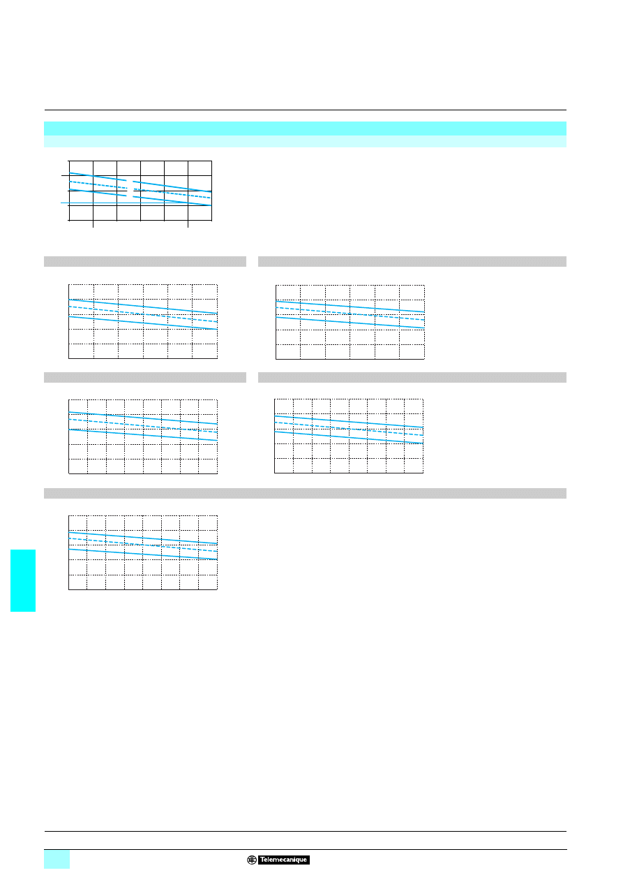
7/68
7
Output characteristics
(continued)
7
Power supplies and transformers
7
Power supplies for DC control circuits
Rectified and filtered power supplies
Phaseo Rectified range
Output characteristics (continued)
Example of how to use the graph
Nominal load current (at 24 V
1)
For an ABL 8TEQ power supply, used with a variable load of 10 to 60 A, on a line supply Un
±10%, the graph gives the limits at the load terminals: 21 and 30 V.
Note: The load lines are represented by vertical lines, images of the nominal current for the load
supplied at its nominal voltage.
1
Nominal line supply +10%
2
Nominal line supply
3
Nominal line supply -10%
ABL 8TEQ24100
ABL 8TEQ24200
ABL 8TEQ24300
ABL 8TEQ24400
ABL 8TEQ24600
15 V
0 A
1 A
2 A
3 A
4 A
5 A
6 A
25 V
30 V
21 V
35 V
1
2
3
10 V
15 V
20 V
25 V
30 V
35 V
5 A
15 A
0 A
10 A
10 V
15 V
20 V
25 V
30 V
35 V
0 A
10 A
20 A
30 A
10 V
15 V
20 V
25 V
30 V
35 V
0 A
25 A
45 A
35 A
15 A
10 V
15 V
20 V
25 V
30 V
35 V
60 A
30 A
0 A
15 A
45 A
10 V
15 V
20 V
25 V
30 V
35 V
0 A
90 A
45 A
Presentation:
page 7/64
References:
page 7/70
Dimensions:
page 7/71
Schemes:
page 7/71
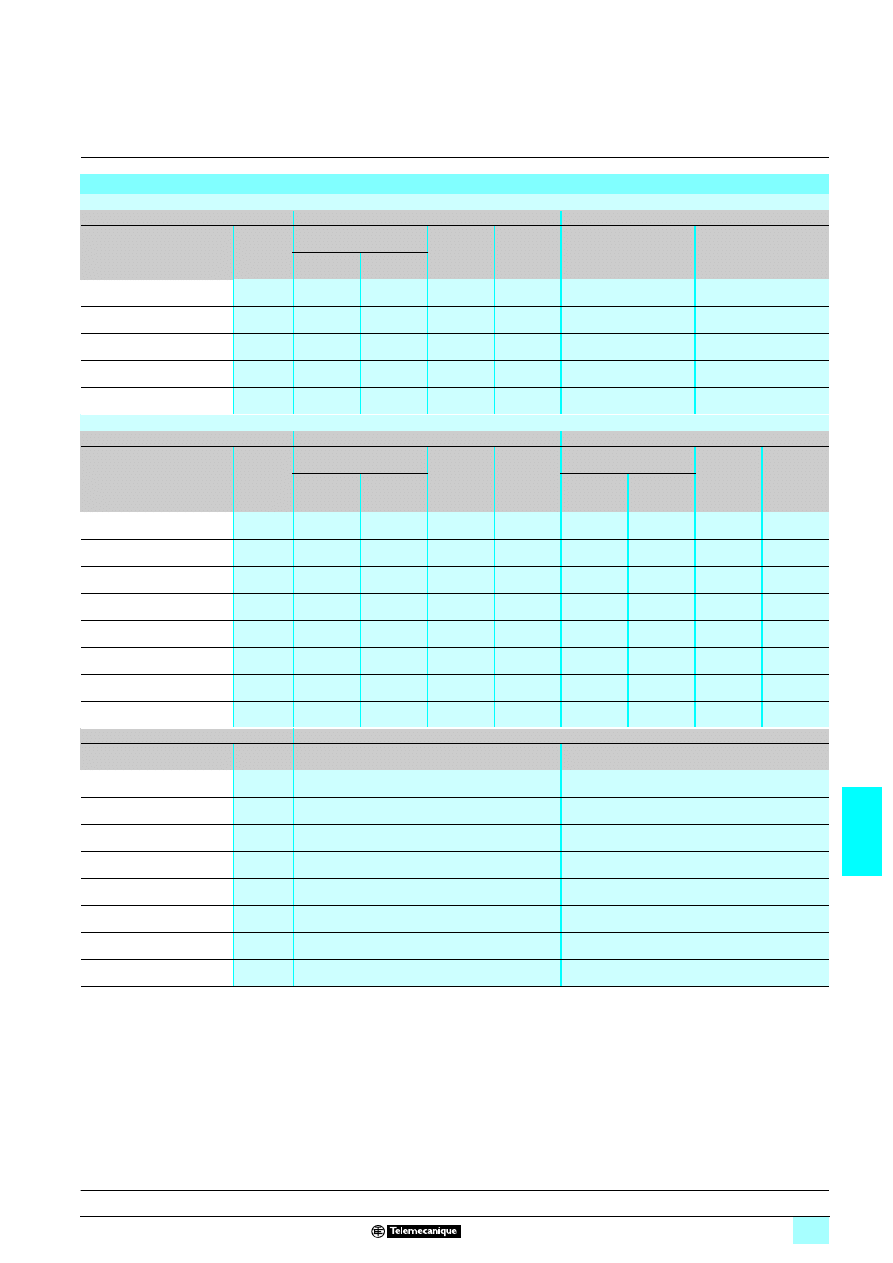
7/69
7
Selection
7
Power supplies and transformers
7
Power supplies for DC control circuits
Rectified and filtered power supplies
Phaseo Rectified range
(1) UL certified circuit-breaker
Selection
ABL 8TEQ power supplies: protection of the primary and secondary voltages
Type of line supply
400 V
2
2
2
2 3-phase, primary voltage
24 V
5
5
5
5, secondary voltage
Type of protection
Nominal
power
3-pole thermal-magnetic
circuit-breaker
UL listed
FNQ type
fuse
aM type
fuse
gC type
fuse
T type
fuse
Telemecanique Merlin Gerin
C60N (1)
ABL 8TEQ24100
240 W
GB2 RT04
24532
0.8 A
1 A
12 A
12 A
ABL 8TEQ24200
480 W
GB2 RT06
17470
1.5 A
1 A
25 A
25 A
ABL 8TEQ24300
720 W
GB2 RT07
24533
2 A
2 A
40 A
–
ABL 8TEQ24400
960 W
GB2 RT07
24534
3 A
2 A
50 A
–
ABL 8TEQ24600
1440 W
GB2 RT08
24535
4 A
4 A
80 A
–
ABL 8FEQ power supplies: protection of the primary and secondary voltages
Type of line supply
400 V
2
2
2
2 single-phase, primary voltage
230 V
2
2
2
2 single-phase, primary voltage
Type of protection
Nominal
power
3-pole thermal-magnetic
circuit-breaker
UL listed
FNQ type
fuse
aM type
fuse
Thermal-magnetic
circuit-breaker
UL listed
MDL type
fuse
aM type
fuse
Telemecanique Merlin Gerin
C60N
2 poles (1)
Telemecanique Merlin Gerin
C60N
1 pole (1)
ABL 8FEQ24005
12 W
GB2 DB05
17451
0.1 A
0.25 A
GB2
11
11
11
1105
17421
0.125 A
0.25 A
ABL 8FEQ24010
24 W
GB2 DB05
17451
0.15 A
0.25 A
GB2
11
11
11
1105
17421
0.2 A
0.25 A
ABL 8FEQ24020
48 W
GB2 DB05
17451
0.3 A
0.25 A
GB2
11
11
11
1105
17421
0.5 A
0.25 A
ABL 8FEQ24040
96 W
GB2 DB06
24516
0.5 A
0.5 A
GB2
11
11
11
1106
24500
1 A
0.5 A
ABL 8FEQ24060
144 W
GB2 DB06
24516
1 A
0.5 A
GB2
11
11
11
1107
17422
1.25 A
1 A
ABL 8FEQ24100
240 W
GB2 DB06
24516
1.25 A
1 A
GB2
11
11
11
1107
24501
2 A
1 A
ABL 8FEQ24150
360 W
GB2 DB07
24517
2 A
1 A
GB2
11
11
11
1108
24502
3 A
2 A
ABL 8FEQ24200
480 W
GB2 DB07
24517
2.5 A
1 A
GB2
11
11
11
1109
24503
4 A
2 A
Type of line supply
24 V
5
5
5
5, secondary voltage
Type of protection
Nominal
power
gC type fuse
T type fuse
ABL 8FEQ24005
12 W
–
0.5 A (internal fuse)
ABL 8FEQ24010
24 W
–
1 A (internal fuse)
ABL 8FEQ24020
48 W
–
2 A (internal fuse)
ABL 8FEQ24040
96 W
–
4 A (internal fuse)
ABL 8FEQ24060
144 W
–
6.3 A (internal fuse)
ABL 8FEQ24100
240 W
12 A
12 A
ABL 8FEQ24150
360 W
20 A
20 A
ABL 8FEQ24200
480 W
25 A
25 A
Presentation:
page 7/64
Characteristics:
pages 7/64 to 7/68
References:
page 7/70
Dimensions:
page 7/71
Schemes:
page 7/71
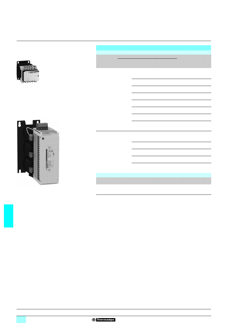
7/70
7
References
7
Power supplies and transformers
7
Power supplies for DC control circuits
Rectified and filtered power supplies
Phaseo Rectified range
References
Rectified and filtered power supplies: Phaseo Rectified range
Input voltage
Secondary
Reference
Weight
kg
Output
voltage
Nominal
power
Output
current
Protection by
5 x 20 fuse
Single-phase (N-L1) or phase-to-phase (L1-L2) connection
230/400 V
2
2
2
2
±10%
50/60 Hz
24 V
3
12 W
0.5 A
Yes
ABL 8FEQ24005
1.280
24 W
1 A
Yes
ABL 8FEQ24010
1.300
48 W
2 A
Yes
ABL 8FEQ24020
2.200
96 W
4 A
Yes
ABL 8FEQ24040
2.900
144 W
6 A
Yes
ABL 8FEQ24060
4.940
240 W
10 A
No
ABL 8FEQ24100
7.660
360 W
15 A
No
ABL 8FEQ24150
8.820
480 W
20 A
No
ABL 8FEQ24200
13.220
Three-phase connection (L1-L2-L3)
400 V
2
2
2
2
± 10%
50/60 Hz
24 V
3
240 W
10 A
No
ABL 8TEQ24100
4.720
480 W
20 A
No
ABL 8TEQ24200
9.900
720 W
30 A
No
ABL 8TEQ24300
13.000
960 W
40 A
No
ABL 8TEQ24400
17.500
1440 W
60 A
No
ABL 8TEQ24600
26.500
Marking accessory
Designation
Size
Order in
multiples of
Unit
reference
Weight
kg
Self-adhesive marker tag
holder
20 x 10 mm
50
AR1 SB3
0.010
ABL 8FEQ24
555
ABL 8TEQ24
500
Presentation:
page 7/64
Characteristics:
pages 7/64 to 7/68
References:
page 7/70
Schemes:
page 7/71
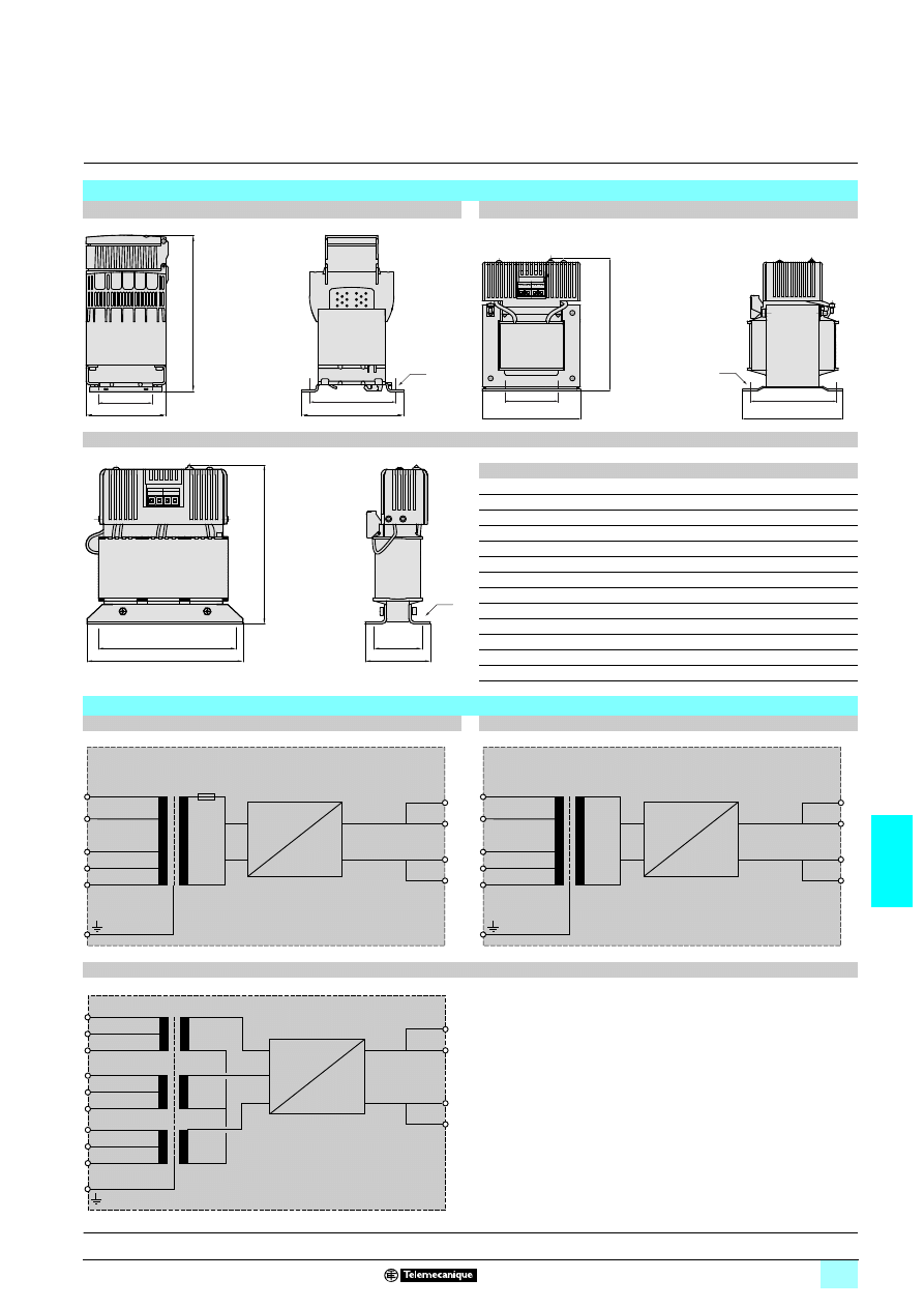
7/71
7
Dimensions,
internal schemes
7
Power supplies and transformers
7
Power supplies for DC control circuits
Rectified and filtered power supplies
Phaseo Rectified range
Dimensions
ABL 8FEQ24005/240
11110/24100
ABL 8FEQ24150/24200
ABL 8TEQ24
111100
ABL
a
b
c
G
J
Ø
8FEQ24005
87
124
108
60
96
5.5
8FEQ24010
87
124
108
60
96
5.5
8FEQ24020
87
142
108
60
96
5.5
8FEQ24040
87
165
108
60
96
5.5
8FEQ24060
123
153
153
82
136
6.5
8FEQ24100
123
185
153
82
136
6.5
8FEQ24150
135
185
138
105
125
6.5
8FEQ24200
175
215
128
135
105
6.5
8TEQ24100
185
190
78
165
58
6.5
8TEQ24200
220
215
104
200
80
8
8TEQ24300
240
252
108
220
87
8
8TEQ24400
310
310
140
260
95
11
8TEQ24600
310
310
154
260
130
11
Internal schemes
ABL 8FEQ24005/24010/24020/24040/24060
ABL 8FEQ24100/24150/24200
ABL 8TEQ24100/24200/24300/24400/24600
J
b
a
c
G
4
∅
a
c
b
G
J
4
∅
a
c
G
J
b
4
∅
400 V
230 V
–
15 V
0 V
+
15 V
0 V
+
24 V
F1
a
c
400 V
230 V
–
15 V
0 V
+
15 V
0 V
+
24 V
a
c
420 V
400 V
0 V
+
24 V
380 V
a
c
420 V
400 V
380 V
420 V
400 V
380 V
Presentation:
page 7/64
Characteristics:
pages 7/64 to 7/68
References:
page 7/70
Schemes:
page 7/71
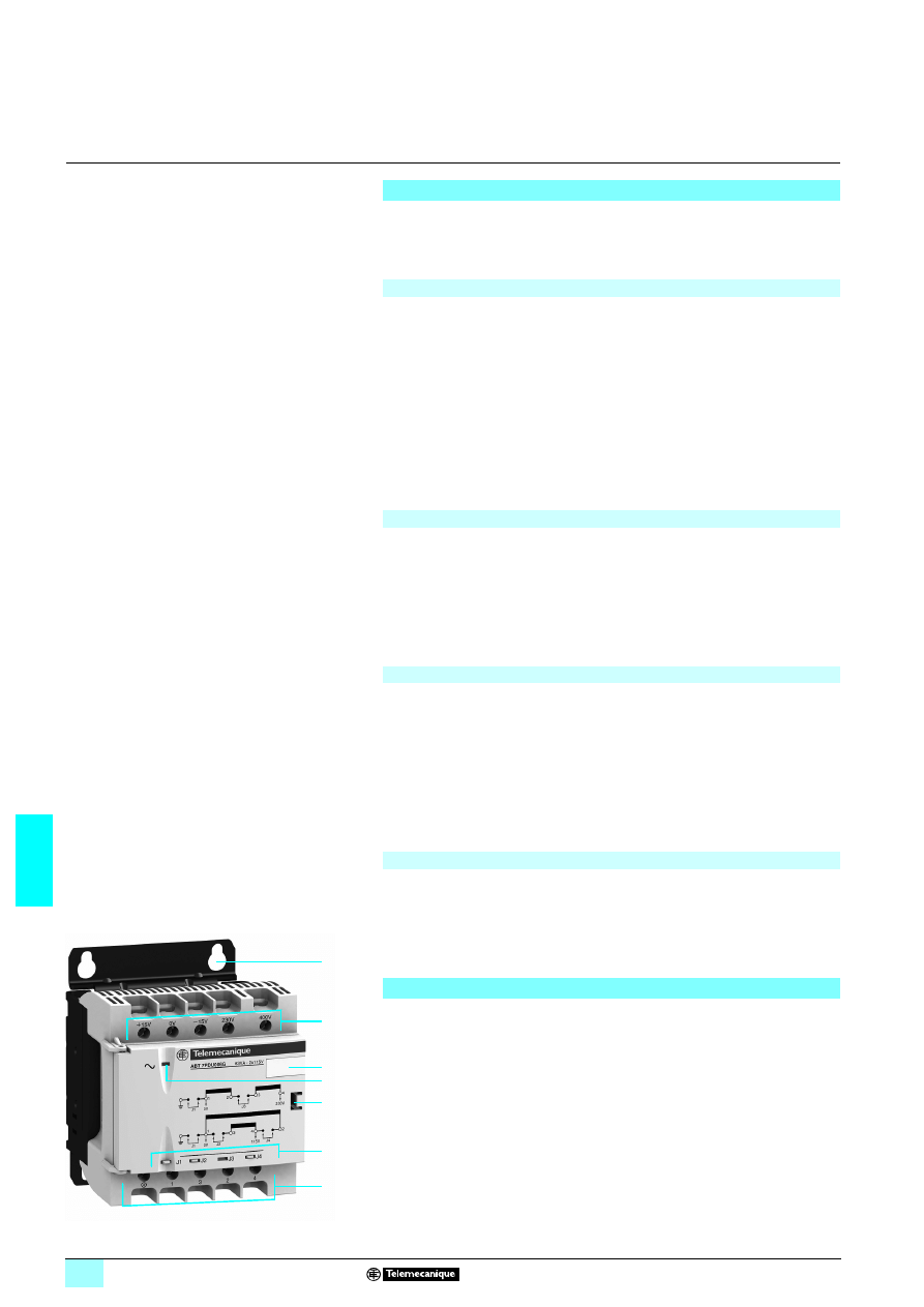
7/72
7
Presentation,
description
7
Power supplies and transformers
7
Safety and isolation transformers (25 to 2500 VA)
The Phaseo ABL 6TS and ABT 7 single-phase transformers offer is designed to
supply control circuits in electrical equipment from a 230 V
5 or 400 V 5 supply
(depending on the model) at 50 or 60 Hz. ± 15 V connectors at the primary ensure
adaptation to the actual values of the supply networks to which they are connected.
This range of transformers with double winding features a particularly innovative
design and offers high-level characteristics (depending on the model) such as:
1 230 V/400 V 5 ± 15 V input voltage
1 2 x 115 V or 2 x 24 V 5 output voltage
1 Clip-on 6 rail mounting (depending on the model) or panel mounting (using 4
screws)
1 Series or parallel connection of secondary winding and grounding via internal
jumpers
1 LED indicator
1 Operating temperature of 60°C
1 cURus, ENEC certifications
All these components are concealed behind a plastic cover making it easier to
integrate the Universal range of Phaseo transformers in control cabinets.
The following characteristics demonstrate the suitability of this tried and tested range
of single-winding transformers for standard applications:
1 230 V/400 V 5 ± 15 V input voltage
1 12 V, 24 V, 115 V or 230 V 5 output voltage
1 Panel mounting, using 4 screws (or clip-on 6 rail-mounting option available
depending on the model)
1 Operating temperature of 50°C
1 cURus certifications
This range of simplified single-winding transformers is primarily designed for repetitive
applications and offers the following as standard:
1 230 V 5 ± 15 V input voltage
1 24 V 5 output voltages
1 Panel mounting using 4 screws
1 Operating temperature of 40°C
ABL 6TS and ABT 7 transformers provide enhanced electrical isolation between the
line supply and the application. The whole range features an electrostatic screen to
limit the spread of electromagnetic interference and improve user safety.
The transformers can be protected against short-circuits by means of fuses or
thermal-magnetic circuit-breakers mounted on the secondary.
For operation in compliance with UL standards, short-circuit protection must be
achieved using fuses (UL approved) mounted on the primary.
Where the control circuit is isolated from the ground (IT system), a leakage detector
will indicate any accidental ground faults.
1
Mounted using 4 screws or, depending on the model in the Universal range, by
clipping on a 35 mm
6 rail
2
Screw terminals with ± 15 V connectors for connection of the AC input voltage
3
Clip-on marker tag or self-adhesive marker tag holder AR1 SB3
4
LED (green) indicating presence of input voltage (depending on the model in the
Universal range)
5
Access to the jumpers for selecting the secondary connection (opened using a
screwdriver)
6
Windows (depending on the model in the Universal range) for viewing the
connection via jumpers of the:
120 V to ground (J1 jumper)
23Series connection, totally freeing up the "customer" secondary wiring capacity
(J3 jumper)
23Parallel connection, totally freeing up the "customer" secondary wiring capacity
(J2 and J4 jumpers)
7
Screw terminals for connection of the AC output voltage
Presentation
Universal range (25 VA to 2500 VA)
Optimum range (25 VA to 2500 VA)
Economic range (25 VA to 400 VA)
Protection
Description
1
2
4
3
6
5
7
ABT 7PDU002
4…7PDU0324
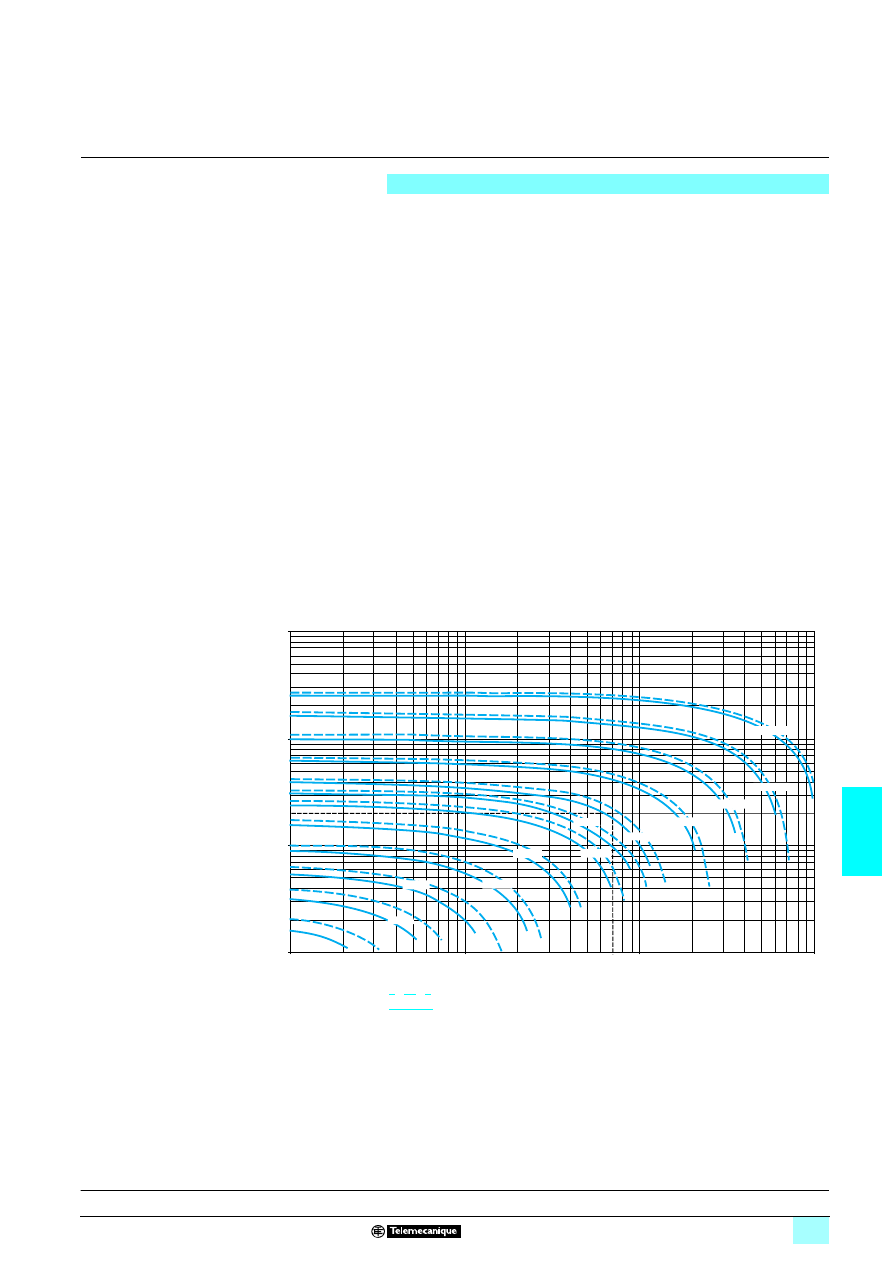
7/73
7
Selection
7
Power supplies and transformers
7
Safety and isolation transformers (25 to 2500 VA)
Selection
ABL 6TS and ABT 7 transformers are characterized by the apparent nominal power
they can supply continuously. However, they are also designed to supply, when
necessary, significantly higher powers, such as contactor inrush peaks.
Contactor inrush peaks can reach 10 to 20 times the required holding current. This
leads to the transformer being oversized in relation to the continuous power it has to
supply. The transformer must be sized so that the voltage drop at its terminals,
caused by the inrush, remains with the permissible limits for the contactor to close
properly.
The two power values that need to be taken into account to determine which
transformer rating to use are therefore:
1 The continuous power the transformer has to supply
1 The maximum inrush power it has to provide
In practice, only the sum of the holding currents and the largest contactor inrush
current need to be considered.
For ABL 6TS transformers, the graph below can be used to select the appropriate rating
according to these two currents. This ensures a maximum voltage drop of 5% at the
moment of inrush, compatible with correct operation of the entire installation. However,
these transformers have been designed for continuous operation at nominal load and
at an ambient temperature of 50°C. A reduction in the ambient temperature may
uprate the transformer, which, in some cases, allows a lower rating to be used.
The graph below has therefore been drawn up for ambient temperatures of 35…50°C.
The inrush values of the contactor coils are given on the contactor control circuit
characteristics pages.
10 000
1000
10
200
100
10
100
80
1000
10 000
63 VA
160 VA
250 VA
400 VA
630 VA
1000 VA
1600 VA
2500 VA
40 VA
25 VA
100 VA
320 VA
Inrush current (VA)
Holding current (VA)
Operation at 35°C
Operation at 50°C
Example: A device with a total holding current of 200 VA and inrush current of the
largest contactor of 700 VA can be supplied by a 630 VA transformer if it is used at
an ambient temperature of 50°C. A 400 VA transformer is sufficient if the ambient
temperature is 35°C.
Characteristics:
pages 7/74 to 7/77
References:
page 7/82
Dimensions:
pages 7/83 and 7/84
Schemes:
page 7/85
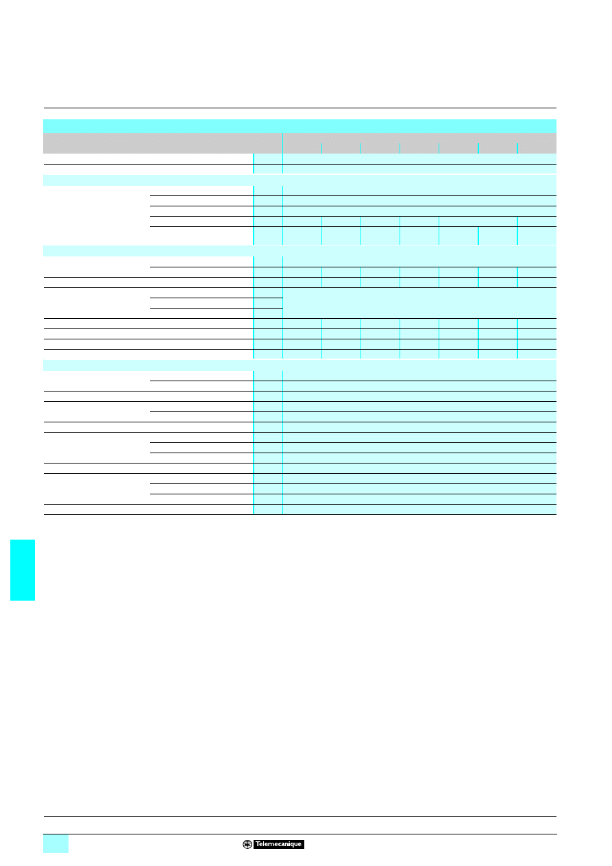
7/74
7
Characteristics
7
Power supplies and transformers
7
Safety and isolation transformers (25 to 2500 VA)
Economic range of transformers
Technical characteristics
Type of transformer
ABT 7ESM
111
111
111
111B
004
006
010
016
025
032
040
Conformity to standards
IEC-61558-2-6, EN-61558-2-6
Product certifications
None
Input circuit
Input values
Nominal voltage
V
230
1 single-phase with - 15 V and + 15 V connectors
Limit voltage
V
207…253
12
Permissible frequencies
Hz
47…63
Efficiency at nominal load
%
74
82
83
87
89
90
Dissipated power at nominal
load
W
14.1
13.8
20.5
23.9
30.9
39.6
44.4
Output circuit
Nominal output values
Voltage
V
24
1
Power
VA
40
63
100
160
250
320
400
Voltage variation at nominal load
%
13.50
11.60
9.25
6.12
5.04
5.08
4.29
Protection
Against short-circuits
External, depending on the power rating, (see page 7/78)
Against overloads
Against overvoltages
Sustained overvoltage (no-load, hot state)
%
15.50
13.60
10.20
7.50
6.30
6.10
5
Voltage drop (at nominal load)
%
15.80
14.13
11.04
7.42
6.25
6.50
5.75
No-load losses
W
3.8
5.7
6.7
9.6
12.3
16.7
19.3
Short-circuit voltage
%
16
13.30
11.30
9
8.30
6.20
5.50
Operating and environmental characteristics
Connections
Input
mm
2
2 x 2.5...4 (AWG 14/11) + ground
Output
mm
2
2 x 2.5...4 (AWG 14/11) + ground
Mounting
On panel (4
∅ 5 mm)
Operating position
Vertical plane
Vertical or horizontal position
Horizontal plane
With derating to 90%
Degree of protection
IP 20 conforming to IEC 60529
Environment
Operating temperature
°C
- 20…+ 40
Storage temperature
°C
- 40…+ 80
Maximum relative humidity
95% during operation
Protection class according to VDE 0106 1
Class I
Dielectric strength
50 Hz for 1 min
Input/output
V rms
5100
1
Input/ground
V rms
3200
1
Output/ground
V rms
3200
1
Electrical insulation class
Class B
Presentation:
page 7/72
Selection of protection:
page 7/78
References:
page 7/82
Dimensions:
page 7/83
Schemes:
page 7/85
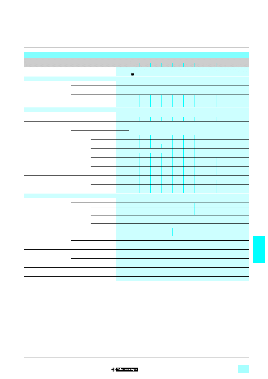
7/75
7
Characteristics
(continued)
7
Power supplies and transformers
7
Safety and isolation transformers (25 to 2500 VA)
Optimum range of transformers
Technical characteristics
Type of transformer
ABL 6TS
02
1111
04
1111
06
1111
10
1111
16
1111
25
1111
40
1111
63
1111
100
1111 1601111 2501111
Conformity to standards
IEC-61558-2-6, EN-61558-2-6, UL 506
Product certifications
Input circuit
Input values
Nominal voltage
V
230 or 400
1 single-phase with - 15 V and + 15 V connectors
Limit voltage
V
207…253
12or 360…440 12
Permissible frequencies
Hz
47…63
Efficiency at nominal load
%
79
81
84
86
88
90
92
93
94
96
96
Dissipated power at nominal
load
6.6
9.4
12.0
16.3
21.8
27.8
34.8
47.4
63.8
66.7
104.2
Output circuit
Nominal output values
Voltage
V
12, 24, 115 or 230
1
Power
VA
25
40
63
100
160
250
400
630
1000
1600
2500
Protection
Against short-circuits
External, depending on the power rating (see page 7/79)
Against overloads
Against overvoltages
Sustained overvoltage
(no-load, hot state)
Secondary
voltage
12 V
1 (J)
%
16
14
9
7
5
–
24 V
1 (B)
%
15
11
9
7
6
4
3
2
115 V
1 (G)
%
15
12
9
8
6
5
4
3
2
3
230 V
1 (U)
%
9
7
5
4
3
Voltage drop
(at nominal load)
Secondary
voltage
12 V
1 (J)
%
0.6
0
1.3
0.3
0.4
0.6
–
24 V
1 (B)
%
0.3
0.2
0.2
0.0
0.3
0.1
0.7
0.5
- 0.3
0.0
0.5
115 V
1 (G)
%
0
0.4
0.1
0.6
0.7
0.7
0.5
0.3
0.5
0.1
- 0.3
230 V
1 (U)
%
5.9
4
1.4
0.6
0.9
0.7
0.7
0.4
5
0.0
0.0
No-load losses
W
3
4.4
5.3
7.1
9.1
12.5
12.4
18.9
26.5
23.7
23.4
Short-circuit voltage
Secondary
voltage
12 V
1 (J)
%
14.74
12.13
9.63
8
6.9
5.47
–
24 V
1 (B)
%
13.52
10.27
8.62
7.86
6.81
5.51
4.50
3.41
2.93
2.50
2.85
115 V
1 (G)
%
14.03
10.71
7.92
7.51
6.65
5.28
4.66
3.47
3.04
2.45
2.61
230 V
1 (U)
%
14.34
11.46
9.08
8.32
7.5
5.85
4.77
3.68
3.24
2.65
8.73
Operating and environmental characteristics
Connections
Primary
mm
2
4 (AWG 11)
Secondary
12 V
1 (J)
mm
2
4 (AWG 11)
–
24 V
1 (B)
mm
2
4 (AWG 11)
10 (AWG 6)
16
(AWG 4)
35
(AWG 2)
115 V
1 (G)
mm
2
4 (AWG 11)
10
(AWG 6)
230 V
1 (U)
mm
2
4 (AWG 11)
Mounting
On panel
4
∅ 4.8 mm or on
4 with
ABL 6AM0
5 plate
4
∅ 5.8 mm
4
∅ 7 mm
4
∅
10 mm
Operating position
Vertical plane
Vertical or horizontal position
Horizontal plane
With derating to 90%
Degree of protection
IP 20 conforming to IEC 60529
Protective treatment
"TC"
Environment
Operating temperature
°C
- 20…+ 50
Storage temperature
°C
- 40…+ 80
Protection class according to VDE 0106 1
Class I
Dielectric strength
50 Hz for 1 min
Primary/secondary
V rms
4000
Winding/ground
V rms
2000
Electrical insulation class
Class F: ABL 6TS160
1111 and ABL 6TS2501111, Class B: other ABL 6TS references
Presentation:
page 7/72
Selection of protection:
page 7/78
References:
page 7/82
Dimensions:
page 7/83
Schemes:
page 7/85
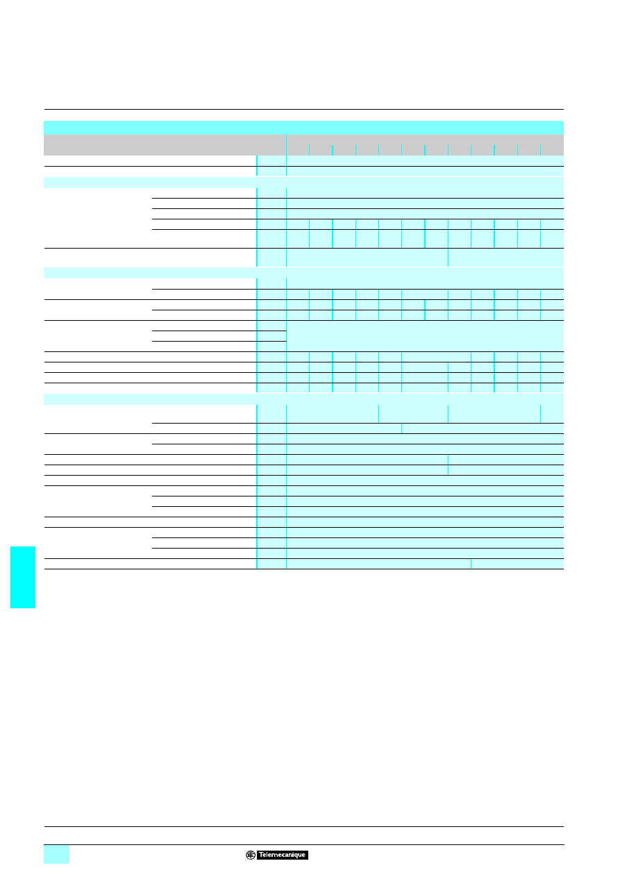
7/76
7
Characteristics
(continued)
7
Power supplies and transformers
7
Safety and isolation transformers (25 to 2500 VA)
Universal range of transformers,
24 or 48 V
4 output voltage
Technical characteristics
Type of transformer
ABT 7PDU
111
111
111
111B
002
004
006
010
016
025
032
040
063
100
160
250
Conformity to standards
IEC-61558-2-6, EN-61558-2-6, UL 506
Product certifications
cURus, ENEC
Input circuit
Input values
Nominal voltage
V
230 or 400
1 single-phase with - 15 V and + 15 V connectors
Limit voltage
V
207…253
12or 360…440 1
Permissible frequencies
Hz
47…63
Efficiency at nominal load
%
74
79
83
86
88
90
91
90
90
92
94
96
Dissipated power at nominal
load
W
8.8
10.6
12.9
16.3
21.8
27.8
31.6
44.4
70.0
87.0
102.1 104.2
Diagnostics
LED (orange) indicating presence of voltage at
the primary
–
Output circuit
Nominal output values
Voltage
V
24 or 48
1 depending on connection
Power
VA
25
40
63
100
160
250
320
400
630
1000
1600
2500
Voltage variation at nominal
load
230
1
%
9.12
6.16
4.79
4.04
3.29
3.12
3.12
3.66
4.16
3.37
2.7
1.45
400
1
%
9.40
6.50
4.70
4.29
3.16
3.00
3.58
3.29
4.54
3.62
3.29
2.12
Protection
Against short-circuits
External, depending on the power rating (see pages 7/80 and7/81)
Against overloads
Against overvoltages
Sustained overvoltage (no-load, hot state)
%
3.30
2.40
3.30
2.60
2.40
2.10
2.30
4.00
4.80
3.70
2.80
0.50
Voltage drop (at nominal load)
%
9.54
6.00
3.88
3.63
2.83
2.50
2.79
3.79
4.37
4.46
3.71
2.29
No-load losses
W
5.07
6.73
8.11
10.69 14.32 14.68 15.10 21.67 24.01 32.95 26.33 40.50
Short-circuit voltage
%
15.10 10.60 7.50
6.60
6.80
6.50
6.70
4.00
5.00
4.70
4.00
2.80
Operating and environmental characteristics
Mounting
On panel
4
∅ 5.5 mm
4
∅ 6.5 mm
4
∅ 7 mm
4
∅
10 mm
On
4 rail
35 x 15 mm
–
Operating position
Vertical plane
Vertical or horizontal position
Horizontal plane
With derating to 90%
Winding connection
Series or parallel
Via internal jumpers
Via external links
Grounding of the secondary
Via internal jumper
–
Degree of protection
IP 20 conforming to IEC 60529
Environment
Operating temperature
°C
- 20…+ 40
Storage temperature
°C
- 40…+ 60
Maximum relative humidity
95% during operation
Protection class according to VDE 0106 1
Class I
Dielectric strength
50 Hz for 1 min
Input/output
V rms
5100
1
Input/ground
V rms
3200
1
Output/ground
V rms
3200
1
Electrical insulation class
Class B
Class F
Presentation:
page 7/72
Selection of protection:
pages 7/80 and7/81
References:
page 7/82
Dimensions:
page 7/83
Schemes:
page 7/85
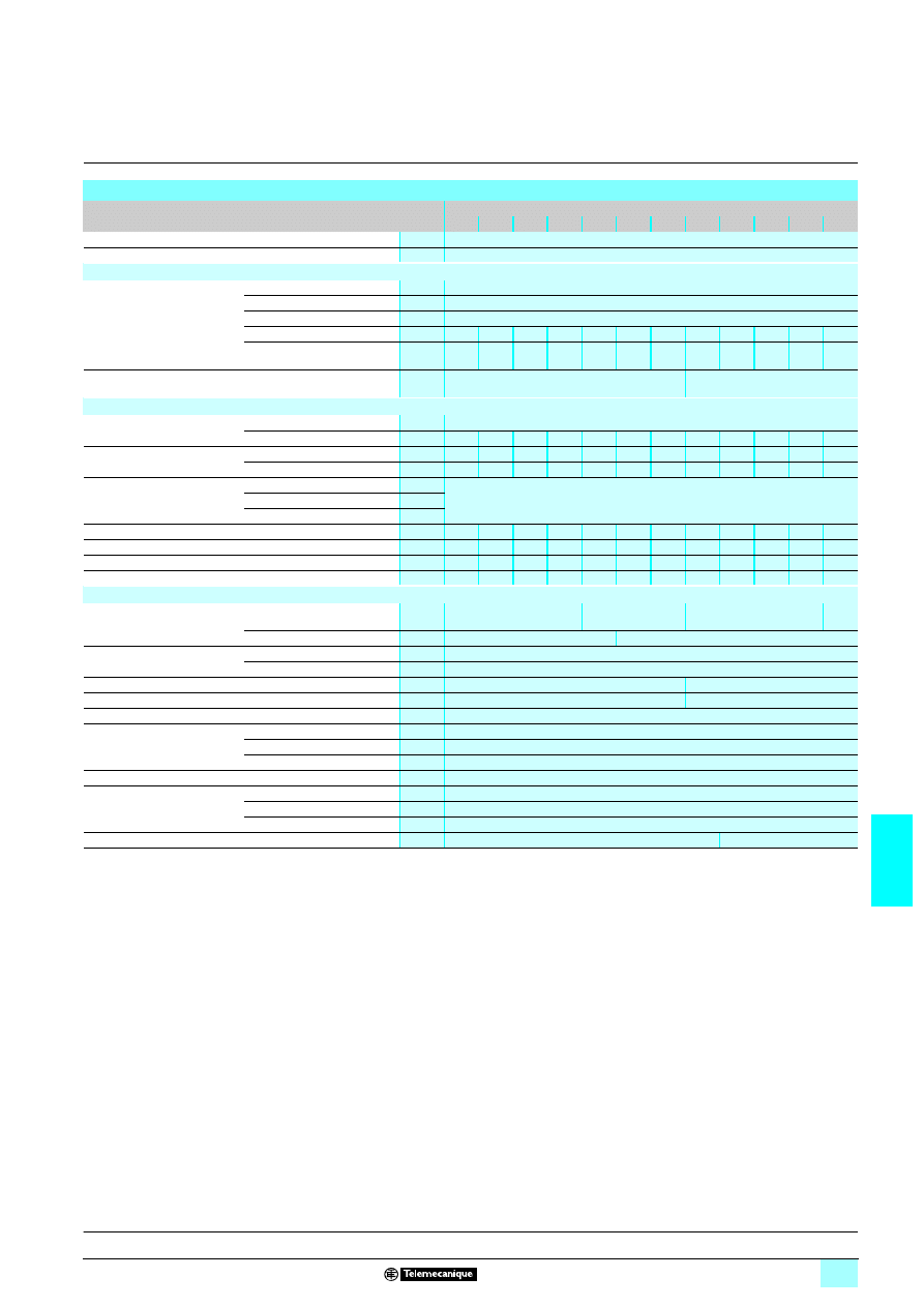
7/77
7
Characteristics
(continued)
7
Power supplies and transformers
7
Safety and isolation transformers (25 to 2500 VA)
Universal range of transformers,
115 or 230 V
4 output voltage
Technical characteristics
Type of transformer
ABT 7PDU
111
111
111
111G
002
004
006
010
016
025
032
040
063
100
160
250
Conformity to standards
IEC-61558-2-6, EN-61558-2-6, UL 506
Product certifications
cURus, ENEC
Input circuit
Input values
Nominal voltage
V
230 or 400
1 single-phase with - 15 V and + 15 V connectors
Limit voltage
V
207…253
12or 360…440 1
Permissible frequencies
Hz
47…63
Efficiency at nominal load
%
76
81
84
86
88
90
91
90
90
92
94
96
Dissipated power at nominal
load
W
7.9
9.4
12.0
16.3
21.8
27.8
31.6
44.4
70.0
87.0
102.1 104.2
Diagnostics
LED (orange) indicating presence of voltage at
the primary
–
Output circuit
Nominal output values
Voltage
V
115 or 230
1 depending on connection
Power
VA
25
40
63
100
160
250
320
400
630
1000
1600
2500
Voltage variation at nominal
load
230
1
%
6.95
5.47
3.82
4.00
3.39
3.13
2.86
3.75
3.58
3.15
3.06
1.70
400
1
%
7.73
5.73
4.26
4.17
3.30
3.13
3.13
3.90
4.17
3.40
2.86
1.89
Protection
Against short-circuits
External, depending on the power rating (see pages 7/80 and7/81)
Against overloads
Against overvoltages
Sustained overvoltage (no-load, hot state)
%
5.40
4.20
2.50
4.90
2.50
1.80
1.40
3.30
4.90
3.50
2.70
1.50
Voltage drop (at nominal load)
%
7.90
6.16
4.28
4.23
3.61
3.37
3.63
4.17
4.89
4.08
3.14
1.70
No-load losses
W
4.89
5.93
7.37
11.26 9.53
13.68 15.68 21.28 23.55 31.09 26.38 31.60
Short-circuit voltage
%
11.50 8.70
6.60
6.20
6.70
6.60
6.80
4.10
4.80
3.80
3.50
2.20
Operating and environmental characteristics
Mounting
On panel
4
∅ 5.5 mm
4
∅ 6.5 mm
4
∅ 7 mm
4
∅
10 mm
On
4 rail
35 x 15 mm
–
Operating position
Vertical plane
Vertical or horizontal position
Horizontal plane
With derating to 90%
Winding connection
Series or parallel
Via internal jumpers
Via external links
Grounding of the secondary
Via internal jumper
–
Degree of protection
IP 20 conforming to IEC 60529
Environment
Operating temperature
°C
- 20…+ 60
Storage temperature
°C
- 40…+ 80
Maximum relative humidity
95% during operation
Protection class according to VDE 0106 1
Class I
Dielectric strength
50 Hz for 1 min
Input/output
V rms
5100
1
Input/ground
V rms
3200
1
Output/ground
V rms
3200
1
Electrical insulation class
Class B
Class F
Presentation:
page 7/72
Selection of protection:
pages 7/80 and7/81
References:
page 7/82
Dimensions:
page 7/83
Schemes:
page 7/85
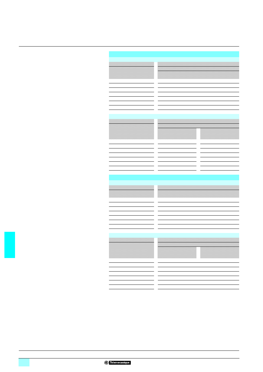
7/78
7
Selection of protection
7
Power supplies and transformers
7
Safety and isolation transformers (25 to 2500 VA)
Economic range
(1) For operation in compliance with UL.
(2) GB2 CB
55: single-pole, GB2 CD55: 1 pole protected and 1 pole switched, GB2 DB55:
2 poles protected. UL certification pending.
Recommended protection for the primary
Protection by fuses
Transformer
230 V
2
2
2
2 single-phase input voltage
Reference
Power
(V
2
2
2
2)
Fuse carrier/isolator
MDL fuses
UL Listed
(1)
aM fuses
ABT 7ESM004B
40
0.3 A
0.5 A
ABT 7ESM006B
63
0.4 A
0.5 A
ABT 7ESM010B 100
0.6
A
1
A
ABT 7ESM016B 160
1
A
2
A
ABT 7ESM025B 250
1.25
A
2
A
ABT 7ESM032B 320
2
A
4
A
ABT 7ESM040B 400
2
A
6
A
Protection by thermal-magnetic circuit-breakers
Transformer
230 V
2
2
2
2 single-phase input voltage
Reference
Power
Circuit-breaker
Telemecanique (2)
GB2 (IEC)
Merlin Gerin
C60N single-pole (IEC)
(UL)
ABT 7ESM004B
40 VA
GB2
5505
17421
ABT 7ESM006B
63 VA
GB2
5505
17421
ABT 7ESM010B
100 VA
GB2
5506
24500
ABT 7ESM016B
160 VA
GB2
5506
24500
ABT 7ESM025B
250 VA
GB2
5507
17422
ABT 7ESM032B
320 VA
GB2
5507
17422
ABT 7ESM040B
400 VA
GB2
5508
24502
Recommended protection for the secondary
Protection by fuses
Transformer
24 V
2
2
2
2 secondary
Reference
Power
(V
2
2
2
2)
Fuses
gG
T
ABT 7ESM004B
40
1 A
1.6 A
ABT 7ESM006B
63
2 A
2.5 A
ABT 7ESM010B 100
4
A
4
A
ABT 7ESM016B 160
6
A
7
A
ABT 7ESM025B
250
10 A
10 A
ABT 7ESM032B
320
12 A
14 A
ABT 7ESM040B
400
16 A
20 A
Protection by thermal-magnetic circuit-breakers
Transformer
24 V
2
2
2
2 secondary
Reference
Power
Circuit-breaker (1)
Telemecanique (2)
GB2 (IEC)
Merlin Gerin
C60N single-pole (IEC)
(UL)
ABT 7ESM004B
40 VA
GB2
5507
24426
ABT 7ESM006B
63 VA
GB2
5508
24427
ABT 7ESM010B
100 VA
GB2
5510
24430
ABT 7ESM016B
160 VA
GB2
5512
24432
ABT 7ESM025B
250 VA
GB2
5520
24434
ABT 7ESM032B
320 VA
GB2
5521
24434
ABT 7ESM040B
400 VA
GB2
5522
24435
Presentation:
page 7/72
Characteristics:
page 7/74
References:
page 7/82
Dimensions:
page 7/83
Schemes:
page 7/85
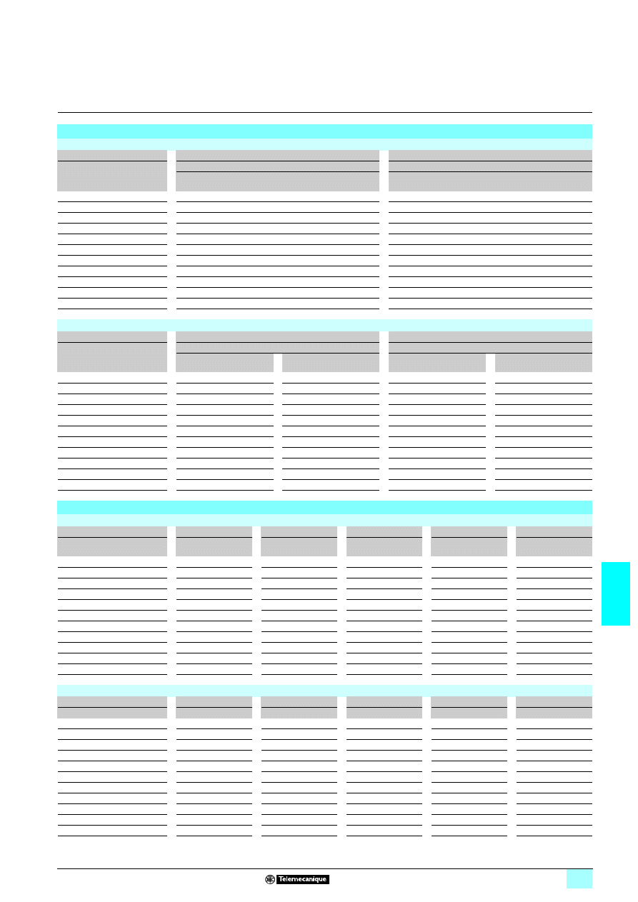
7/79
7
Selection of protection
(continued)
7
Power supplies and transformers
7
Safety and isolation transformers (25 to 2500 VA)
Optimum range
Recommended protection for the primary
Protection by fuses
Transformer
230 V
2
2
2
2 single-phase input voltage
400 V
2
2
2
2 single-phase input voltage
Reference
Power
(V
2
2
2
2)
Fuse carrier/isolator
Fuse carrier/isolator
MDL fuses
UL Listed
(1)
aM fuses
MDL fuses
UL Listed
(1)
aM fuses
ABL 6TS002
1111
25
2/10 A
0.5 A
15/100 A
0.5 A
ABL 6TS004
1111
40
1/4 A
0.5 A
15/100 A
0.5 A
ABL 6TS006
1111
63
4/10 A
0.5 A
2/10 A
0.5 A
ABL 6TS010
1111
100
6/10 A
1 A
3/10 A
0.5 A
ABL 6TS016
1111
160
1 A
2 A
1/2 A
1 A
ABL 6TS025
1111
250
1 1/2 A
2 A
8/10 A
1 A
ABL 6TS040
1111
400
2 A
4 A
12/10 A
2 A
ABL 6TS063
1111
630
3 2/10 A
6 A
2 A
4 A
ABL 6TS100
1111
1000
5 A
8 A
3 A
6 A
ABL 6TS160
1111
1600
8 A
10 A
5 A
8 A
ABL 6TS250
1111
2500
2 A
16 A
7 A
10 A
Protection by thermal-magnetic circuit-breakers
Transformer
230 V
2
2
2
2 single-phase input voltage
400 V
2
2
2
2 single-phase input voltage
Reference
Power
Circuit-breaker
Circuit-breaker
Telemecanique (2)
GB2 (IEC)
Merlin Gerin
C60N single-pole (IEC) (UL)
Telemecanique (2)
GB2 2-pole (IEC)
Merlin Gerin
C60N 2-pole (IEC) (UL)
ABL 6TS002
1111
25 VA
GB2
5505
17421
GB2 DB05
17451
ABL 6TS004
1111
40 VA
GB2
5505
17421
GB2 DB05
17451
ABL 6TS006
1111
63 VA
GB2
5505
17421
GB2 DB05
17451
ABL 6TS010
1111
100 VA
GB2
5506
24500
GB2 DB05
17451
ABL 6TS016
1111
160 VA
GB2
5507
17422
GB2 DB06
24516
ABL 6TS025
1111
250 VA
GB2
5507
17422
GB2 DB06
24516
ABL 6TS040
1111
400 VA
GB2
5508
24502
GB2 DB07
24517
ABL 6TS063
1111
630 VA
GB2
5510
24503
GB2 DB08
24518
ABL 6TS100
1111
1000 VA
GB2
5514
24504
GB2 DB09
24519
ABL 6TS160
1111
1600 VA
GB2
5520
–
GB2 DB14
24520
ABL 6TS250
1111
2500 VA
–
–
GB2 DB20
24522
Recommended protection for the secondary
Protection by fuses
Transformer
12 V
2
2
2
2 secondary
24 V
2
2
2
2 secondary
48 V
2
2
2
2 secondary
115 V
2
2
2
2 secondary
230 V
2
2
2
2 secondary
Reference
Power
(V
2
2
2
2)
Fuses
gG
T
Fuses
gG
T
Fuses
gG
T
Fuses
gG
T
Fuses
gG
T
ABL 6TS002
1111
25
2 A
2 A
1 A
1 A
0.5 A
0.5 A
–
0.2 A
–
0.1 A
ABL 6TS004
1111
40
4 A
3.15 A
1 A
1.6 A
0.5 A
0.8 A
–
0.315 A
–
0.16 A
ABL 6TS006
1111
63
6 A
5 A
2 A
2.5 A
1 A
1.25 A
0.5 A
0.5 A
–
0.25 A
ABL 6TS010
1111
100
8 A
–
4 A
4 A
2 A
2 A
0.5 A
0.8 A
–
0.4 A
ABL 6TS016
1111
160
12 A
–
6 A
–
2 A
3.15 A
1 A
1.4 A
0.5 A
0.63 A
ABL 6TS025
1111
250
20 A
–
10 A
–
4 A
5 A
2 A
2 A
1 A
1 A
ABL 6TS040
1111
400
–
–
16 A
–
8 A
–
2 A
3.15 A
1 A
1.6 A
ABL 6TS063
1111
630
–
–
25 A
–
12 A
–
4 A
5 A
2 A
2.5 A
ABL 6TS100
1111
1000
–
–
40 A
–
20 A
–
8 A
–
4 A
4 A
ABL 6TS160
1111
1600
–
–
63 A
–
32 A
–
12 A
–
6 A
–
ABL 6TS250
1111
2500
–
–
100 A
–
50 A
–
20 A
–
10 A
–
Protection by thermal-magnetic circuit-breakers
Transformer
12 V secondary
24 V
2
2
2
2 secondary
48 V
2
2
2
2 secondary
115 V
2
2
2
2 secondary
230 V
2
2
2
2 secondary
Reference
Power
Circuit-breaker (2)
Circuit-breaker (2)
Circuit-breaker (2)
Circuit-breaker (2)
Circuit-breaker (2)
ABL 6TS002
1111
25 VA
GB2
5507 24426
GB2
5506 24425
–
–
–
–
–
–
ABL 6TS004
1111
40 VA
GB2
5509 24428
GB2
5507 24426
–
–
–
17411
–
–
ABL 6TS006
1111
63 VA
GB2
5510 24430
GB2
5508 24427
–
–
GB2
5505 24425
–
–
ABL 6TS010
1111
100 VA
GB2
5514 24432
GB2
5509 24428
–
–
GB2
5506 24425
GB2
5505 17411
ABL 6TS016
1111
160 VA
–
24434
GB2
5512 24430
–
–
GB2
5507 24426
GB2
5506 24425
ABL 6TS025
1111
250 VA
–
24435
GB2
5516 24432
–
–
GB2
5507 24426
GB2
5506 24425
ABL 6TS040
1111
400 VA
–
–
–
24434
–
–
GB2
5508 24428
GB2
5507 24426
ABL 6TS063
1111
630 VA
–
–
–
24436
–
–
GB2
5510 24430
GB2
5508 24427
ABL 6TS100
1111
1000 VA
–
–
–
24438
–
–
GB2
5514 24432
GB2
5509 24428
ABL 6TS160
1111
1600 VA
–
–
–
24440
–
–
GB2
5520 24434
GB2
5512 24430
ABL 6TS250
1111
2500 VA
–
–
–
–
–
–
–
24435
GB2
5516 24432
(1) For operation in compliance with UL.
(2) Telemecanique circuit-breaker (IEC), GB2 CB
55: single-pole, GB2 CD55: 1 pole protected and 1 pole switched, GB2 DB55: 2 poles protected. UL certification
pending. Merlin Gerin circuit-breaker (IEC, UL), 24
555.

7/80
7
Selection of protection
(continued)
7
Power supplies and transformers
7
Safety and isolation transformers (25 to 2500 VA)
Universal range
Recommended protection for the primary
Protection by fuses
Transformer
230 V
2
2
2
2 single-phase input voltage
400 V
2
2
2
2 single-phase input voltage
Reference
Power
(V
2
2
2
2)
Fuse carrier/isolator
Fuse carrier/isolator
MDL fuses
UL Listed
(1)
aM fuses
MDL fuses
UL Listed
(1)
aM fuses
ABT 7PDU002
1111
25
0.2 A
0.25 A
0.15 A
0.25 A
ABT 7PDU004
1111
40 0.25 A
0.25 A
0.2 A
0.25 A
ABT 7PDU006
1111
63
0.4 A
0.25 A
0.3 A
0.25 A
ABT 7PDU010
1111
100
0.6 A
0.5 A
0.4 A
0.5 A
ABT 7PDU016
1111
160
1 A
0.5 A
0.6 A
0.5 A
ABT 7PDU025
1111
250
1.5 A
1 A
1 A
1 A
ABT 7PDU032
1111
320
2 A
1 A
1.25 A
1 A
ABT 7PDU040
1111
400
2.5 A
2 A
1.5 A
2 A
ABT 7PDU063
1111
630
4 A
2 A
2.5 A
2 A
ABT 7PDU100
1111
1000
6 A
4 A
3.5 A
4 A
ABT 7PDU160
1111
1600
8 A
6 A
5 A
6 A
ABT 7PDU250
1111
2500
–
8 A
8 A
8 A
Protection by thermal-magnetic circuit-breakers
Transformer
230 V
2
2
2
2 single-phase input voltage
400 V
2
2
2
2 single-phase input voltage
Reference
Power
Circuit-breaker
Circuit-breaker
Telemecanique (2)
GB2 (IEC)
Merlin Gerin
C60N single-pole (IEC) (UL)
Telemecanique (2)
GB2 (IEC)
Merlin Gerin
C60N single-pole (IEC) (UL)
ABT 7PDU002B/G 25 VA
GB2
5505
17421
GB2 DB05
17451
ABT 7PDU004B/G 40 VA
GB2
5505
17421
GB2 DB05
17451
ABT 7PDU006B/G 63 VA
GB2
5505
17421
GB2 DB05
17451
ABT 7PDU010B/G 100 VA
GB2
5506
24500
GB2 DB05
17451
ABT 7PDU016B/G 160 VA
GB2
5506
24500
GB2 DB06
24516
ABT 7PDU025B/G 250 VA
GB2
5507
17422
GB2 DB06
24516
ABT 7PDU032B/G 320 VA
GB2
5507
17422
GB2 DB06
24516
ABT 7PDU040B/G 400 VA
GB2
5508
24502
GB2 DB07
24517
ABT 7PDU063B/G 630 VA
GB2
5509
24503
GB2 DB07
24517
ABT 7PDU100B/G 1000 VA
GB2
5512
24504
GB2 DB08
24518
ABT 7PDU160B/G 1600 VA
GB2
5514
–
GB2 DB10
24520
ABT 7PDU250B/G 2500 VA
GB2
5520
–
GB2 DB14
24522
(1) For operation in compliance with UL.
(2) GB2 CB
55 : single-pole, GB2 CD55: 1 pole protected and 1 pole switched, GB2 DB55: 2 poles protected. UL certification pending.
Presentation:
page 7/72
Characteristics:
pages 7/76 and 7/77
References:
page 7/82
Dimensions:
page 7/84
Schemes:
page 7/85
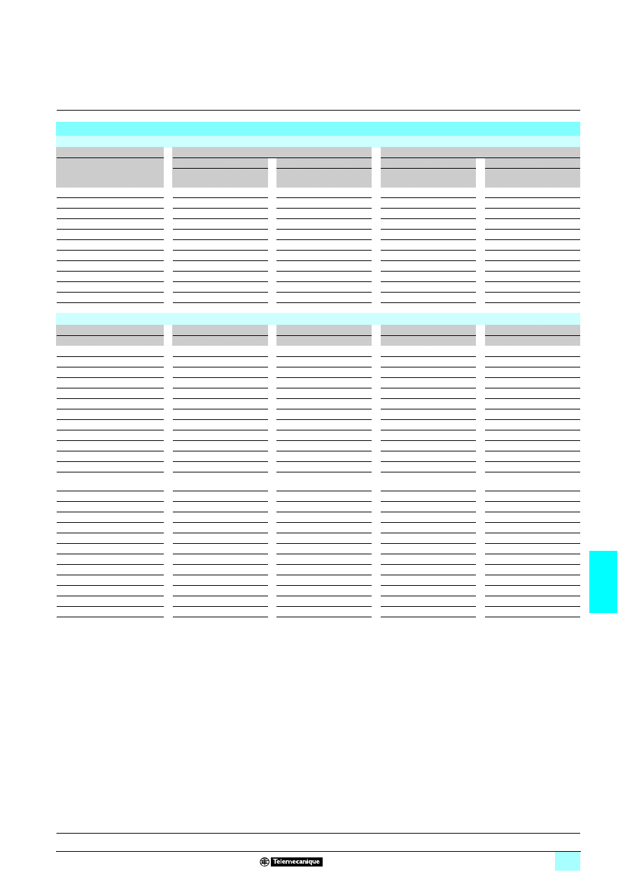
7/81
7
Selection of protection
(continued)
7
Power supplies and transformers
7
Safety and isolation transformers (25 to 2500 VA)
Universal range
Recommended protection for the secondary
Protection by fuses
Transformer
2 x 24 V
2
2
2
2 secondary
2 x 115 V
2
2
2
2 secondary
Reference
Power
(V
2
2
2
2)
Parallel connection
Series connection
Parallel connection
Series connection
Fuses
gG
T
Fuses
gG
T
Fuses
gG
T
Fuses
MDL
aM
ABT 7PDU002
1111
25
1 A
1 A
0.5 A
0.5 A
0.5 A
0.4 A
0.2 A
0.25 A
ABT 7PDU004
1111
40 1 A
1.6 A
0.5 A
0.8
A
0.5
A
0.5 A
0.25 A
0.25 A
ABT 7PDU006
1111
63
2 A
2.5 A
1 A
1.25 A
0.5 A
0.8 A
0.4 A
0.25 A
ABT 7PDU010
1111
100
4 A
4 A
2 A
2 A
0.5 A
1.25 A
0.6 A
0.5 A
ABT 7PDU016
1111
160
6 A
7 A
2 A
3.15 A
1 A
2 A
1 A
0.5 A
ABT 7PDU025
1111
250
10 A
10 A
4 A
5 A
2 A
3 A
1.5 A
1 A
ABT 7PDU032
1111
320
12 A
14 A
6 A
7 A
2 A
4 A
2 A
1 A
ABT 7PDU040
1111
400
16 A
20 A
8 A
10 A
2 A
5 A
2.5 A
2 A
ABT 7PDU063
1111
630
25 A
30 A
12 A
14 A
4 A
8 A
4 A
2 A
ABT 7PDU100
1111
1000
40 A
–
20 A
20 A
8 A
10 A
6 A
4 A
ABT 7PDU160
1111
1600
63 A
–
32 A
–
12 A
15 A
8 A
6 A
ABT 7PDU250
1111
2500
100 A
–
50 A
–
20 A
25 A
12 A
8 a
Protection by thermal-magnetic circuit-breakers
Transformer
24 V
2
2
2
2 secondary
48 V
2
2
2
2 secondary
115 V
2
2
2
2 secondary
230 V
2
2
2
2 secondary
Reference
Power
Circuit-breaker (1)
Circuit-breaker (1)
Circuit-breaker (1)
Circuit-breaker (1)
ABT 7PDU002B
25 VA
GB2
5507
24426
GB2
5506
24425
–
–
–
–
ABT 7PDU004B
40 VA
GB2
5507
24426
GB2
5506
24425
–
–
–
–
ABT 7PDU006B
63 VA
GB2
5508
24427
GB2
5507
24426
–
–
–
–
ABT 7PDU010B
100 VA
GB2
5510
24430
GB2
5508
24427
–
–
–
–
ABT 7PDU016B
160 VA
GB2
5512
24432
GB2
5509
24428
–
–
–
–
ABT 7PDU025B
250 VA
GB2
5520
24434
GB2
5512
24430
–
–
–
–
ABT 7PDU032B
320 VA
GB2
5521
24434
GB2
5514
24432
–
–
–
–
ABT 7PDU040B
400 VA
GB2
5522
24435
GB2
5516
24432
–
–
–
–
ABT 7PDU063B
630 VA
–
24437
GB2
5521
24434
–
–
–
–
ABT 7PDU100B
1000 VA
–
24439
–
24436
–
–
–
–
ABT 7PDU160B
1600 VA
–
–
–
24438
–
–
–
–
ABT 7PDU250B
2500 VA
–
–
–
24440
–
–
–
–
ABT 7PDU002G
25 VA
–
–
–
–
GB2
5505
24425
GB2
5505
24425
ABT 7PDU004G
40 VA
–
–
–
–
GB2
5505
24425
GB2
5505
24425
ABT 7PDU006G
63 VA
–
–
–
–
GB2
5506
24425
GB2
5505
24425
ABT 7PDU010G
100 VA
–
–
–
–
GB2
5506
24425
GB2
5505
24425
ABT 7PDU016G
160 VA
–
–
–
–
GB2
5507
24426
GB2
5506
24425
ABT 7PDU025G
250 VA
–
–
–
–
GB2
5508
24427
GB2
5507
24426
ABT 7PDU032G
320 VA
–
–
–
–
GB2
5508
24427
GB2
5507
24426
ABT 7PDU040G
400 VA
–
–
–
–
GB2
5509
24428
GB2
5507
24426
ABT 7PDU063G
630 VA
–
–
–
–
GB2
5512
24430
GB2
5508
24427
ABT 7PDU100G
1000 VA
–
–
–
–
GB2
5516
24430
GB2
5510
24430
ABT 7PDU160G
1600 VA
–
–
–
–
GB2
5521
24434
GB2
5514
24432
ABT 7PDU250G
2500 VA
–
–
–
–
–
24438
GB2
5520
24434
(1) Telemecanique circuit-breaker (IEC), GB2 CB
55: single-pole, GB2 CD55: 1 pole protected and 1 pole switched, GB2 DB55: 2 poles protected. UL certification
pending. Merlin Gerin circuit-breaker (IEC, UL), 241
44.
Presentation:
page 7/72
Characteristics:
pages 7/76 and 7/77
References:
page 7/82
Dimensions:
page 7/84
Schemes:
page 7/85
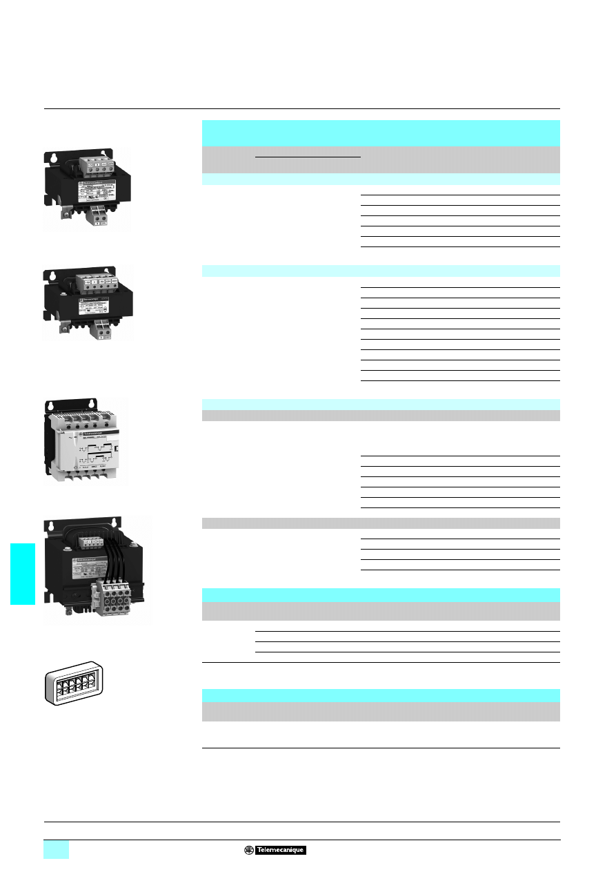
7/82
7
References
7
Power supplies and transformers
7
Safety and isolation transformers (25 to 2500 VA)
Transformers with phase-to-neutral (N-L1) or phase-to-phase (L1-L2)
connection
Input
voltage
Secondary
Nominal
power
Reference to be
completed (1)
Secondary
voltage
marking
Weight
kg
Type
Voltage
Economic range of transformers
230 V ± 15 V
single-phase,
50/60 Hz
Single winding 24 V (B) 40 VA
ABT 7ESM004B –
1.020
63 VA
ABT 7ESM006B –
1.140
100 VA
ABT 7ESM010B –
1.900
160 VA
ABT 7ESM016B –
2.720
250 VA
ABT 7ESM025B –
3.540
320 VA
ABT 7ESM032B –
4.080
400 VA
ABT 7ESM040B –
5.100
Optimum range of transformers
230/400 V
± 15 V
single-phase
50/60 Hz
Single winding 12 V (J)
or 24 V (B)
or 115 V (G)
or 230 V (U)
25 VA
ABL 6TS02
5
J B G U
0.700
40 VA
ABL 6TS04
5
J B G U
1.200
63 VA
ABL 6TS06
5
J B G U
1.600
100 VA
ABL 6TS10
5
J B G U
2.100
160 VA
ABL 6TS16
5
J B G U
3.200
250 VA
ABL 6TS25
5
J B G U
4.400
400 VA
ABL 6TS40
5
B G U
6.500
630 VA
ABL 6TS63
5
B G U
9.800
1000 VA
ABL 6TS100
5
B G U
14.300
1600 VA
ABL 6TS160
5
B G U
19.400
2500 VA
ABL 6TS250
5
B G U
27.400
Universal range of transformers
With cover, connected by internal jumpers with LED indicators
230/400 V
± 15 V
single-phase
50/60 Hz
Double winding 2 x 24 V (B)
or
2 x 115 V (G)
25 VA
ABT 7PDU002
5 B G
1.100
40 VA
ABT 7PDU004
5 B
G
1.400
63 VA
ABT 7PDU006
5 B
G
1.940
100 VA
ABT 7PDU010
5
B G
2.860
160 VA
ABT 7PDU016
5
B G
4.400
250 VA
ABT 7PDU025
5
B G
5.600
320 VA
ABT 7PDU032
5
B G
7.100
Without cover, connected by external jumpers
230/400 V
± 15 V
single-phase
50/60 Hz
Double winding 2 x 24 V (B)
or
2 x 115 V (G)
400 VA
ABT 7PDU040
5
B G
7.400
630 VA
ABT 7PDU063
52 B G
7.900
1000 VA
ABT 7PDU100
5
B G
14.000
1600 VA
ABT 7PDU160
5
B G
20.000
2500 VA
ABT 7PDU250
5
B G
28.000
Separate parts
Designation
Use
Order in
multiples of
Unit reference
Weight
kg
Plates for
mounting
on
4 rail
Optimum transfo. ABL 6TS02
5
5
ABL 6AM00
0.045
Optimum transfo. ABL 6TS04
5
5
ABL 6AM01
0.050
Optimum transfo. ABL 6TS06
5
5
ABL 6AM02
0.055
Optimum transfo. ABL 6TS10
5
5
ABL 6AM03
0.065
Self-adhesive
marker tag
holder
20 x 10 mm
50
AR1 SB3
0.001
Replacement parts
Designation
Use
Reference
Weight
kg
Pack of 10
jumpers
Universal range double-winding transformer
ABT 7JMP01
0.010
(1) Reference to be completed with the marking on the secondary voltage.
ABL 7ESM0
55B
ABL 6TS
555
ABT 7PDU002
5…0325
ABT 7PDU040
5…2505
AR1 SB3
Presentation:
page 7/72
Characteristics:
pages 7/74 and 7/77
Selection of protection:
pages 7/78 and 7/81
Dimensions:
pages 7/83 and 7/84
Schemes:
page 7/85
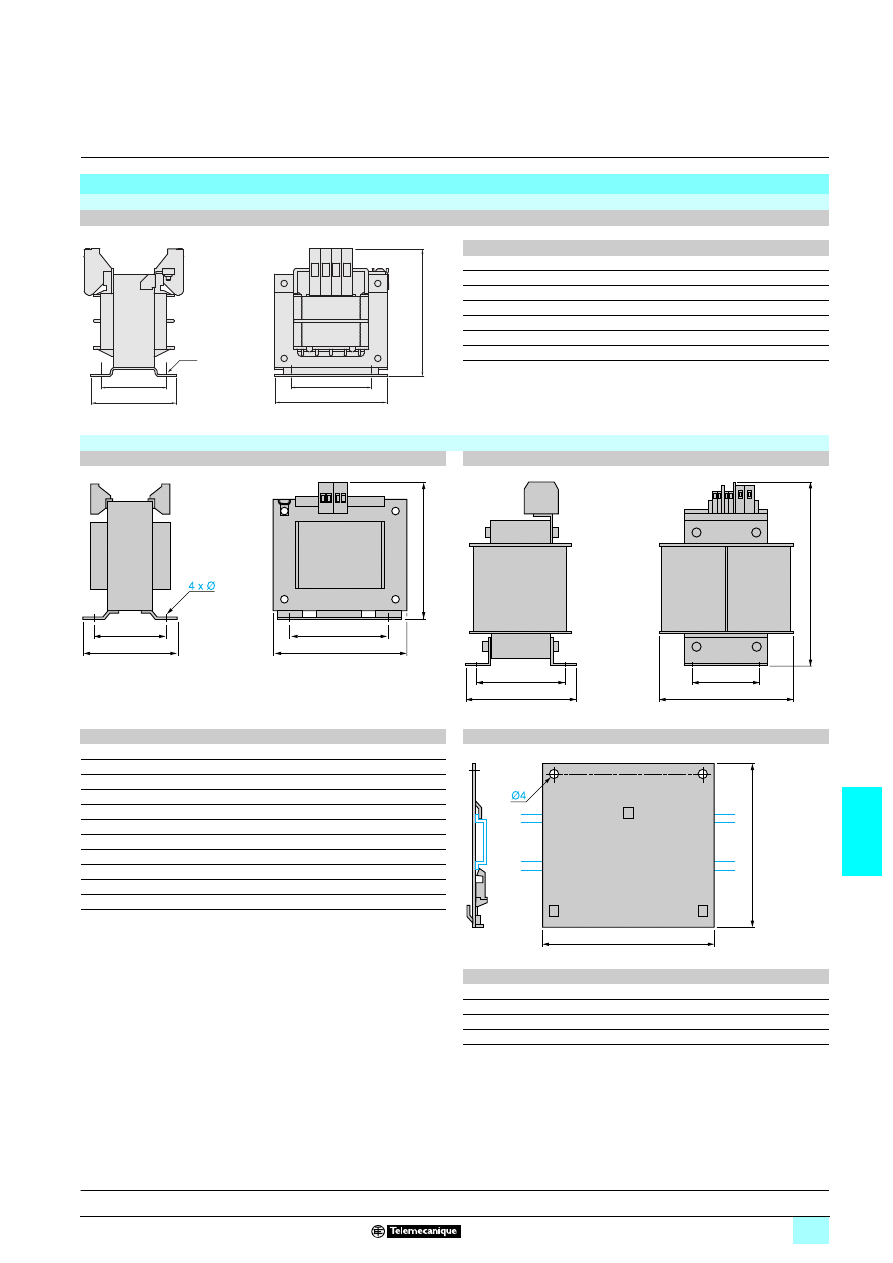
7/83
7
Dimensions
7
Power supplies and transformers
7
Safety and isolation transformers (25 to 2500 VA)
Dimensions
Economic range of transformers
ABT 7ESM00
1111B/011111B/025B/032B/040B
ABT
a
b
c
G
J
Ø
7ESM004B
79
90
70
56
48
5
7ESM006B
79
90
70
56
48
5
7ESM010B
85
94
86
64
67
5
7ESM016B
97
104
92
84
78
5
7ESM025B
98
106
105
84
86
5
7ESM032B
121
122
92
90
75
5
7ESM040B
121
122
103
90
86
5
Optimum range of transformers
ABL 6TS002
1111 to ABL 6TS1001111
ABL 6TS160
1111 and ABL 6TS2501111
ABL
a
b
c
G
J
Ø
ABL 6AM0
1111 mounting plates
6TS002
1111
66
90
55
55
42
4.8
6TS004
1111
78
90
68
56
47.5
4.8
6TS006
1111
78
90
80
56
56
4.8
6TS010
1111
85
94
86
64
65.5
4.8
6TS016
1111
106
109
81
80.5
63
5.8
6TS025
1111
120
122
85
90
74.5
5.8
6TS040
1111
136
140
120
104
87
5.8
6TS063
1111
150
152
138
122
107.5
7
6TS100
1111
174
180
146
135
111.5
7
6TS160
1111
174
221
167
135
138
7
6TS250
1111
198
335
145
125
117
10
ABL
a
b
6AM00
68
70
6AM01
78
70
6AM02
78
74
6AM03
84
78
c
a
b
J
G
4
∅
J
c
b
a
G
a
b
c
G
J
b
a
Presentation:
page 7/72
Characteristics:
pages 7/74 and 7/77
Selection of protection:
pages 7/78 and 7/81
References:
page 7/82
Schemes:
page 7/85
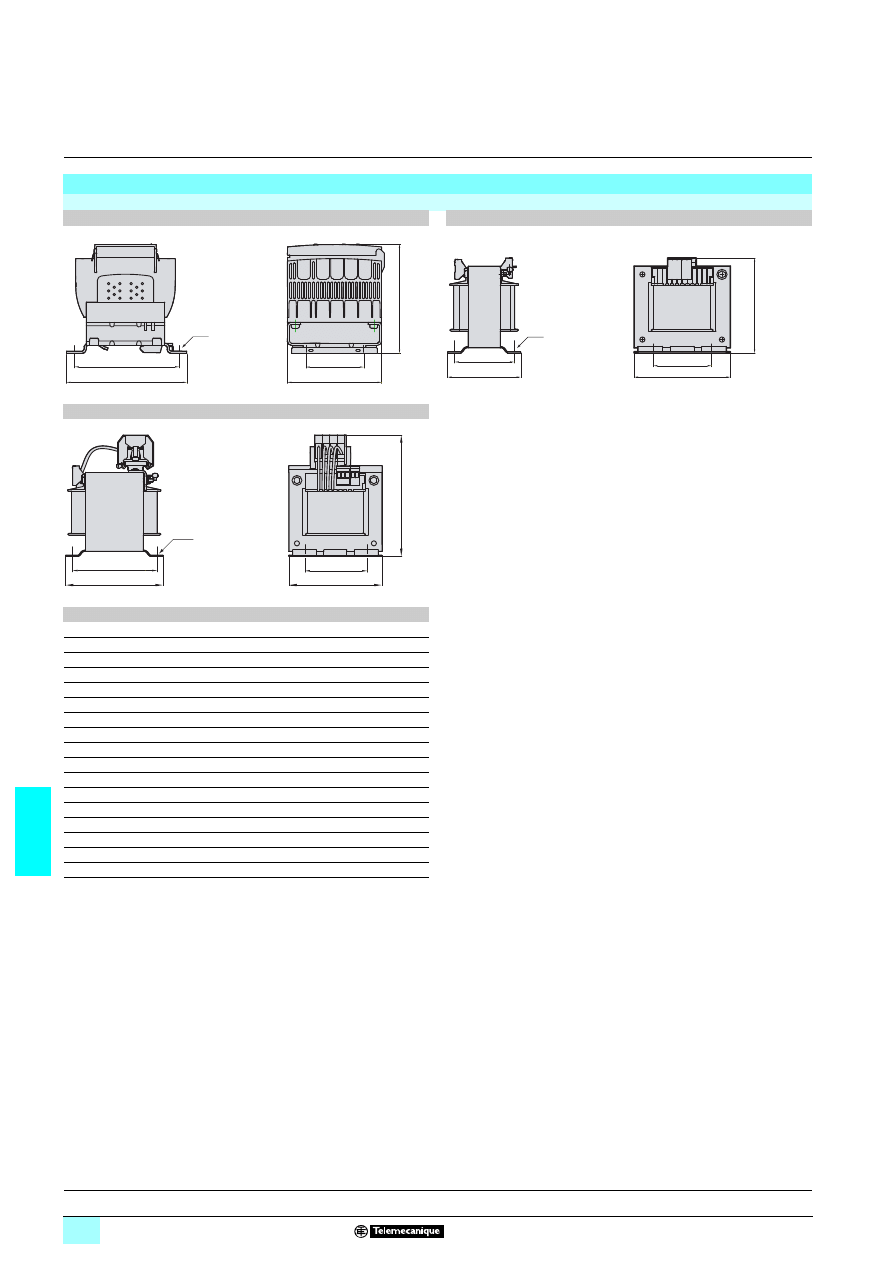
7/84
7
Dimensions
(continued)
7
Power supplies and transformers
7
Safety and isolation transformers (25 to 2500 VA)
Dimensions
(continued)
ABT 7PDU
1111
1111
1111
1111 transformers
ABT 7PDU002
1111/0041111/0061111/0101111/0251111/0321111
ABT 7PDU040
1111/0631111/1006/1606/2506
ABT 7PDU100B/160B/250B
ABT
a
b
c
G
J
Ø
7PDU002
1111
85
98
108
60
96
5.5
7PDU004
1111
87
104
108
60
96
5.5
7PDU006
1111
87
116
108
60
96
5.5
7PDU010
1111
87
139
108
60
96
5.5
7PDU016
1111
123
128
153
82
136
6.5
7PDU025
1111
123
142
153
82
136
6.5
7PDU032
1111
123
160
153
82
136
6.5
7PDU040B
151
160
113
122
95
7
7PDU040G
151
146
113
122
95
7
7PDU063B
151
166
125
122
95
7
7PDU063G
151
146
113
122
95
7
7PDU100B
151
197
157
122
140
7
7PDU100G
151
146
156
122
140
7
7PDU160B
175
222
170
135
145
7
7PDU160G
175
162
168
135
145
7
7PDU250B
193
245
188
150
150
10
7PDU250G
193
206
188
150
150
10
a
c
b
J
G
4
∅
c
b
a
J
G
4
∅
a
b
c
J
G
4
∅
Presentation:
page 7/72
Characteristics:
pages 7/74 and 7/77
Selection of protection:
pages 7/78 and 7/81
References:
page 7/82
Schemes:
page 7/85
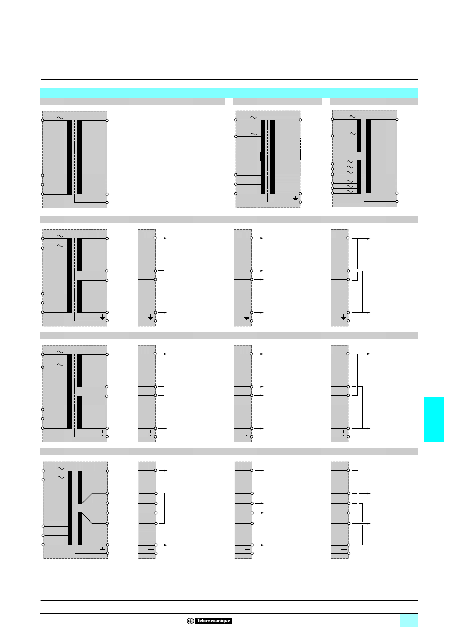
7/85
7
Internal schemes
7
Power supplies and transformers
7
Safety and isolation transformers (25 to 2500 VA)
Internal schemes
ABT 7ESM004B to ABT 7ESM040B
ABL 6TS002
5 to ABL 6TS1605
ABL 6TS250
5
ABT 7PDU002B to ABT 7PDU032B, ABT 7PDU100B to ABT 7PDU250B
ABT 7PDU002G to ABT 7PDU032G
ABT 7PDU040B and ABT 7PDU063B, ABT 7PDU040G to ABT 7PDU250G
230 V
- 15 V
+ 15 V
0 V
400 V
230 V
- 15 V
+ 15 V
0 V
0/400 V
0/230 V
240 V
220 V
230 V
420 V
380 V
400 V
1
4
48 V
0 V
400 V
- 15 V
+ 15 V
0 V
1
2
3
4
1
4
24 V2
0 V1
0 V2
24 V1
1
4
24 V
0 V
2
3
2
3
2
3
230 V
1
4
230 V
0 V
400 V
- 15 V
+ 15 V
0 V
1
4
1
4
115 V2
0 V1
0 V1
115 V2
1
4
115 V
0 V
2
3
2
3
2
3
2
3
230 V
400 V
- 15 V
+ 15 V
0 V
1
5
2
6
4
3
1
48 V (B)
230 V (G)
0 V
5
2
6
4
3
1
24 V2 (B)
115 V2 (G)
0 V1
0 V2
24 V2 (B)
115 V2 (G)
5
2
6
4
3
1
24 V (B)
115 V (G)
0 V
5
2
6
4
3
230 V
Presentation:
page 7/72
Characteristics:
pages 7/74 and 7/77
Selection of protection:
pages 7/78 and 7/81
References:
page 7/82
Dimensions:
pages 7/83 and 7/84

7/86
7
Substitution table
7
Old reference
New reference
Fonctionnal characteristics, to check in case of product substitution
Regulated switch mode power supplies
ABL 7RM1202
ABL 8MEM12020
Distance of fixing
ABL 7RM2401
ABL 8MEM24012
Distance of fixing
ABL 7RM24025
ABL 7RM24025
–
ABL 7CEM24003
ABL 8MEM24003
Dimensions, location and size of terminal blocks
ABL 7CEM24006
ABL 8MEM24006
Dimensions, location and size of terminal blocks
ABL 7CEM24012
ABL 8MEM24012
Dimensions, location and size of terminal blocks
ABL 7RE2402
ABL 8REM24030
–
ABL 7RE2403
ABL 8REM24030
–
ABL 7RE2405
ABL 8REM24050
–
ABL 7RE2410
ABL 8RPS24100
Depth of cabinet, location and number of connecting terminals
ABL 7RP2405
ABL 8RPS24050
Location of terminal blocks
ABL 7RP2410
ABL 8RPS24100
Depth of cabine, location and number of connecting terminals
ABL 7REQ24050
ABL 8RPS24050
Height of product, location of terminal blocks
ABL 7REQ24100
ABL 8RPS24100
Dimensions, location of terminal blocks
ABL 7UEQ24100
ABL 8RPS24100
Raccordement au réseau, dimensions, location of terminal blocks
ABL 7UEQ24200
ABL 8WPS24200
Dimensions, type of fixing, location of terminal blocks
ABL 7UES24050
ABL 8RPS24050
Connection to line supply, height of product, location of terminal blocks
ABL 7UPS24100
ABL 8RPS24100
Connection to line supply, dimensions, location of terminal blocks
ABL 7UPS24200
ABL 8WPS24200
Dimensions, type of fixing, location of terminal blocks
ABL 7UPS24400
ABL 8WPS24400
Dimensions, type of fixing, location of terminal blocks
ABL 1
555
ABL 1
555
–
ASI ABL
555
ASI ABL
555
–
Rectified and filtered power supplies
ABL 6RF2401
ABL 8FEQ24010
Dimensions, distance of fixing
ABL 6RF2402
ABL 8FEQ24020
Dimensions, distance of fixing
ABL 6RF2405
ABL 8FEQ24060
Dimensions, distance of fixing
ABL 6RF2410
ABL 8FEQ24100
Dimensions, distance of fixing
ABL 6RF2415
ABL 8FEQ24150
Dimensions, distance of fixing
ABL 6RF2420
ABL 8FEQ24200
Dimensions, distance of fixing
ABL 6RT2410
ABL 8TEQ24100
Dimensions, distance of fixing
ABL 6RT2420
ABL 8TEQ24200
Dimensions, distance of fixing
ABL 6RT2430
ABL 8TEQ24300
Dimensions, distance of fixing
ABL 6RT2440
ABL 8TEQ24400
Dimensions, distance of fixing
Safety and isolation transformers
ABL 6TS
555
ABL 6TS
555
–
ABL 6TD02B
ABT 7PDU002B
Dimensions, distance of fixing
ABL 6TD02G
ABT 7PDU002G
Dimensions, distance of fixing
ABL 6TD04B
ABT 7PDU004B
Dimensions, distance of fixing
ABL 6TD04G
ABT 7PDU004G
Dimensions, distance of fixing
ABL 6TD06B
ABT 7PDU006B
Dimensions, distance of fixing
ABL 6TD06G
ABT 7PDU006G
Dimensions, distance of fixing
ABL 6TD10B
ABT 7PDU010B
Dimensions, distance of fixing
ABL 6TD10G
ABT 7PDU010G
Dimensions, distance of fixing
ABL 6TD16B
ABT 7PDU016B
Dimensions, distance of fixing
ABL 6TD16G
ABT 7PDU016G
Dimensions, distance of fixing
ABL 6TD25B
ABT 7PDU025B
Dimensions, distance of fixing
ABL 6TD25G
ABT 7PDU025G
Dimensions, distance of fixing
ABL 6TD40B
ABT 7PDU040B
Dimensions, distance of fixing
ABL 6TD40G
ABT 7PDU040G
Dimensions, distance of fixing
ABL 6TD63B
ABT 7PDU063B
Dimensions, distance of fixing
ABL 6TD63G
ABT 7PDU063G
Dimensions, distance of fixing
ABL 6TD100B
ABT 7PDU100B
Dimensions, distance of fixing
ABL 6TD100G
ABT 7PDU100G
Dimensions, distance of fixing
ABL 6TD160B
ABT 7PDU160B
Dimensions, distance of fixing
ABL 6TD160G
ABT 7PDU160G
Dimensions, distance of fixing
ABL 6TD250B
ABT 7PDU250B
Dimensions, distance of fixing
ABL 6TD250G
ABT 7PDU250G
Dimensions, distance of fixing

7/87
7
Wyszukiwarka
Podobne podstrony:
ch7
ch7
CH7 (3)
cisco2 ch7 focus AC6SFLBHTHU6KY5ZZICPKNWKCNKEFDMXOENYZEY
ch7
ch7
ch7
Ch7 Model Space & Layouts
ch7 031102
Ch7 Constrain Sketches
Ch7 PolicyAndInstitutionalFactorsAffectingForestEnergy
Ch7 FuelsAndCombustion
cisco2 ch7 vocab BV5KK4QJZKQRTF3IC3MN3ODFN7YEWK6SOIOS6TY
cisco2 ch7 concept GKEEPVQ7US3W7UGSEZGK7LPOCNZT2DEHL2WAIMQ
Ch7 E2
Ch7 Q1
ch7 pl p1
Ch7 Pgs243 258
więcej podobnych podstron