SPITFIRE
SPITFIRE
Mk II a
SUPERMARINE
Print the kit on color printer with maximal resolution.
Use special coated paper.
50
50
100
100
150
150
scale
PRECISE CARD MODEL
1/48
You can use pencils and water based paints
to weather the model before cutting its parts.
ACES HIGH
There goes the siren that warns of the air raid
Then comes the sound of the guns sending flak
Out of the scramble we’ve got to get airborne
Got to get up for the coming attack
Jump in the cockpit and start up the engines
Remove all the wheel blocks there’s no time to waste
Gathering speed as we head down the runway
Gotta get airborne before it’s too late
Running, scrambling, flying
Rolling, scrambling, diving, going in again
Run, live to fly, fly to live, do or die
Run, live to fly, fly to live, Aces high
Move into fire at the main stream of bombers
Let off a sharp burst and then turn away
Roll over, spin round and come in behind them
Move to their blind sides and firing again
Bandits at 8 o’clock moving behind us
Ten ME-109’s out of the sun
Ascending and turning our Spitfires to face them
Heading straight for them I press down my guns
Rolling, turning, diving,
Rolling, turning, diving, going in again
Run, live to fly, fly to live, do or die
Run, live to fly, fly to live, Aces high
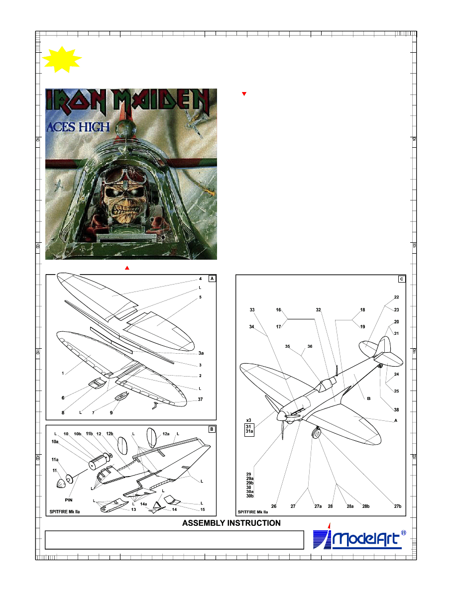
The cover artwork of the Iron Maiden album
The text of the Iron Maiden song
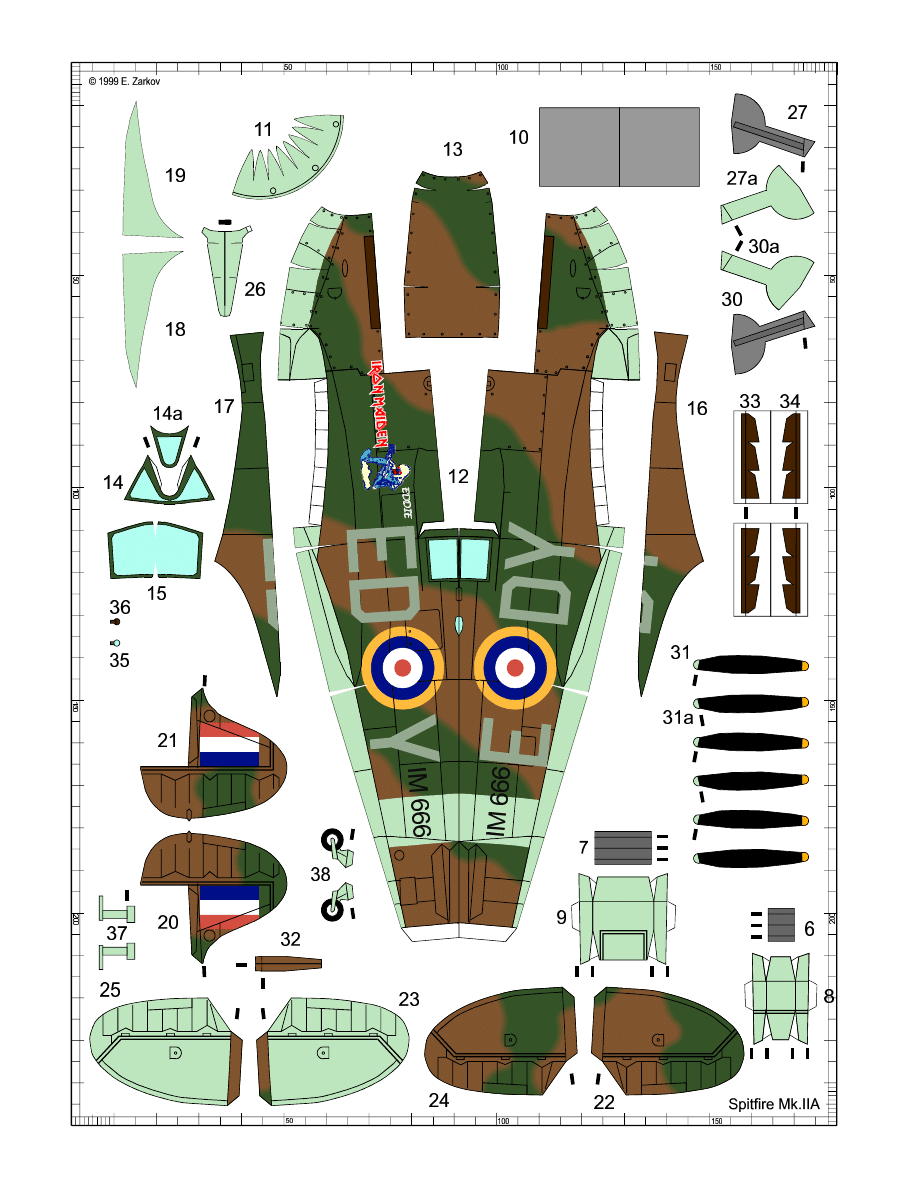
© 1999 E. Zarkov
50
50
100
100
150
150
Glue the red numbered
parts on 0.3 mm card
before cutting them
50
50
100
100
150
150
Study drawings of assembly steps carefully before
starting the work on the model. Make sure you
understand the purpose and place of every part.
The assembly requires some basic tools, such as
scissors, sharp modeling knife, blunt knife for
scoring the fold lines, ruler and needle. Additional
materials you need are one pin to make the
propeller’s shaft and a piece of cardboard approx.
0.3 mm thick for reinforcing elements and wheels.
You'll need of course suitable cement too. For
cement application you can use toothpicks or some
similar tool (special fine cement applicator is most
suitable if you have one).
First of all you must score with the blunt knife all fold
lines shown on the cutouts with short thick marks
near the parts. To avoid mistakes and lost parts cut
the necessary details shortly before their use.
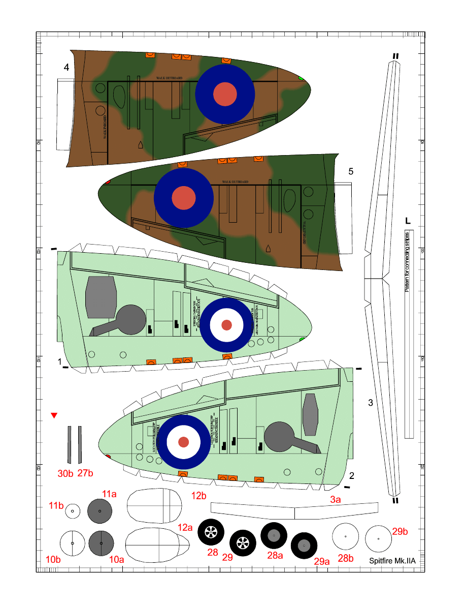
Start with the wing. Cut lower halves 1 and 2 and
don't forget the cut in their front part near the wing
root, which is necessary to form the wing's V-shape
later. Bend the joint elements inwards and carefully
form each half. Try to represent the characteristic
shape of the wing - fuselage joint, as shown on the
drawing. Cut from joint elements [L] stripes with
suitable length and use them to assemble the wing's
lower part from the two halves. Cut and bend the
wing’s part 3 and cement the reinforcing element 3a
to it.
Cut and shape the upper halves of the wing.
Cement the spar 3 to the wing's lower part. Test the
fit of the wing’s upper and lower parts and cement
them together. Watch out for the wing profile and
avoid warping.
Drill holes in the center of the forming parts 10a and
10b, then make the cylindrical body 10 through
which the propeller's axle is protruding.
Make the propeller's shaft cementing the pin's head
to the forming part 11a, as shown on the drawing.
The pin must be coaxial with the cylinder's 10
centerline. Put the pin into the cylinder, then cement
the limiting disc 11b on the pin's rear end. The
propeller's shaft must turn free in the cylinder's
body, but with minimal clearance. Then make and
cement the spinner 11 to the forming part 11a.
Cut the fuselage 12 and pay attention to the cuts in
it - you must make them with maximal accuracy. Cut
the forming parts 12a and 12b and make the
necessary joint elements [L]. Carefully shape the
fuselage - all edges of the small cuts must join
together and then must be reinforced with [L]
elements cemented from inside. Give elliptical
shape to the fuselage and cement it starting from
the rear lower section. Be careful and avoid warping.
Put the bulkhead 12a on its place and cement it to
the fuselage. It's a very tricky job and requires
special attention. Any inaccuracy will result in
fuselage warping or crooking. The same is valid for
the front lower fuselage part. When this fuselage
section is ready too, put the fire wall 12b inside and
cement the cylinder-shaft-spinner subassembly to
the nose fuselage part. Be extremely careful - use
cement sparingly to prevent cementing of the
rotating shaft. Make the upper part of the engine
cowling 13 as shown on the drawing and cement i
t
to the fuselage. Don't forget that the propeller shaft's
axle (i.e. the pin) must be coaxial with fuselage
centerline.
The next step is the canopy - parts 14, 14a and 15.
You have a choice of normal or armored windshield
for the canopy. Alternative parts are with the same
numbers, but the number's color is dark blue.
Make the canopy, cement it on its place; then
cement the assembled wing to the fuselage. Beware
of any warping and crooking.
Cut the aerodynamic wing-fuselage joints 16, 17, 18
and 19. Parts 16 and 17 must have double-curved
shape. To ease your job cut parts 16 and 17 on
some places. The cuts must be perpendicular to
their contour lines. For cleaner job it's recommended
to apply cement not on these parts, but on their
attachment points on the wing and fuselage.
Cut and assemble the horizontal and vertical tail
(parts 20 25) and cement them to the fuselage as
shown on the drawing.
Now it is time for details - oil and cooling liquid
radiators, armament, propeller’s blades, antenna's
mast, rear view mirror, exhausts and carburetor's air
intake. Follow the instruction drawings for their
assembly.
If you want to have an aircraft with extended landing
gear, make the wheels from cardboard (parts 28,
28a, 28b; 29, 29a and 29b) and paint their edges
with suitable paint - water based or acrylic; the
easiest way is to use black marker.
If you prefer a flying model, make your aircraft with
retracted main landing gear. In this case you can
omit parts 10, 10a, 10b; 11b; 27, 27b; 28, 28a, 28b;
29, 29a, 29b; 30, 30b; 31 and 31a, using only the
forming part 11a for the fuselage front part. Put
some weight in the nose to balance the flying model.
The model's center of gravity must be on approx.
25% from the wing chord.
Now your model is ready. Enjoy your Spitfire!
ASSEMBLY INSTRUCTION
Wyszukiwarka
Podobne podstrony:
(paper model)(mały modelarz 01 1959)polski parowóz pt 47 TXHIJ2ZLF4EVBIUZNK4BG4RLCURZMRTJCMLX3MI
[Paper Model] [Maly Modelarz 1963 11] Polish Mielec TS 11 Iskra Jet Trainer
[Paper Model] [German Mickey Mouse Club] [Airplane] 1982 Goofy's Hang Glider
[Paper Model] [Maly Modelarz 1990 07] Messerschmitt Me109
[Paper Model][Airplane][Fiddlers Green] Wright Glider of 1902 (1of2)
[Paper Model] [Space Craft] [Betexa 041] ATLANTIS Space Shuttle [1=72, jpg s]
[Paper Model] [Maly Modelarz 1963 11] Polish Mielec TS 11 Iskra Jet Trainer
[Paper Model] [German Mickey Mouse Club] [Airplane] 1982 Goofy s Hang Glider
[Paper Model] [Maly Modelarz 1990 07] Messerschmitt Me109
(paper model)[maly modelarz 12 1986] renault r17 tank
[Paper Model] [Submarine] [Wilhelmshavner] U 96 Type VII C U Boat
[Papermodels@emule] [Maly Modelarz 1971 04] British Tank Cromwell
[Paper Model] [Building] [Morris] Eastbourne Signal Cabin
[Paper Model] [Pmodel] US Air Force F 86E
[Paper Model] [Auto] [YMjr] Expert Beer Truck
[Paper Model] Foldup paper Modeling
[Paper Model] [Pmodel] US Air Force F 86E
[Paper Model] [Warhammer 40k] Space Marine Whirlwind
więcej podobnych podstron