MANUAL CONTROL HEATING, VENTILATION, AND AIR CONDITIONING SYSTEM 7B -- 21
DAEWOO M-150 BL2
D18B511B
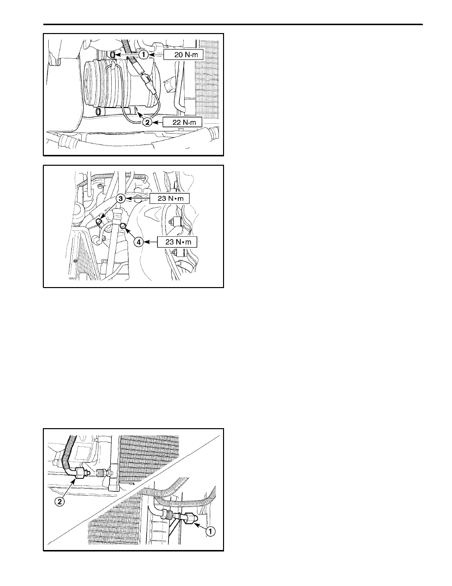
Installation Procedure
1. Install the compressor with the mounting bolts.
Tighten
D
Tighten the compressor--to--bracket upper bolt to
20 NSm (15 lb-ft) (1).
D
Tighten the compressor--to--bracket lower bolts to
22 NSm (16 lb-ft) (2).
2. Connect the electrical connector.
D18B512A
3. Install the A/C high pressure pipe line to the compres-
sor with the bolt.
Tighten
Tighten the A/C high pressure pipe line bolt to 23 NSm
(17 lb-ft) (3).
4. Install the A/C low pressure pipe line to the compres-
sor with the bolt.
Tighten
Tighten the A/C low pressure pipe line bolt to 23 NSm
(17 lb-ft) (4).
5. Evacuate and charge the system. Refer to “Discharg-
ing, Adding Oil, Evacuating, and Charging Procedure
for A/C System” in this section.
6. Install the A/C belt. Refer to Section 6B, Power Steer-
ing Pump.
7. Install the receiver dryer. Refer to “Receiver Dryer
and Dual Cut Switch” in this section.
D18B513A
CONDENSER
1. Disconnect the negative battery cable.
2. Remove the front bumper fascia. Refer to Section
9O, Bumpers and Fascias.
3. Discharge and recover the refrigerant. Refer to “Dis-
charging, Adding Oil, Evacuating, and Charging Pro-
cedures for A/C system” in this section.
4. Remove the condenser.
D
Loosen the condenser pipe--to--compressor pipe
fitting (1).
D
Loosen the condenser pipe--to--receiver dryer pipe
fitting (2).
7B -- 22 MANUAL CONTROL HEATING, VENTILATION, AND AIR CONDITIONING SYSTEM
DAEWOO M-150 BL2
D18B514A
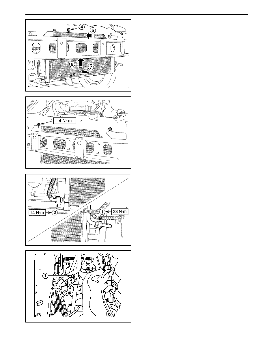
D
Remove the condenser mounting nuts (3).
D
Push the top of the condenser (4).
D
Take off the condenser from the lower bracket by
lifting the condenser (5).
D
Remove the condenser (6).
D18B515B
Installation Procedure
Important: Discard the removed O--rings.
1. Install the condenser with the nuts.
Tighten
Tighten the condenser mounting nuts to 4 NSm (36 lb-
in).
D18B516B
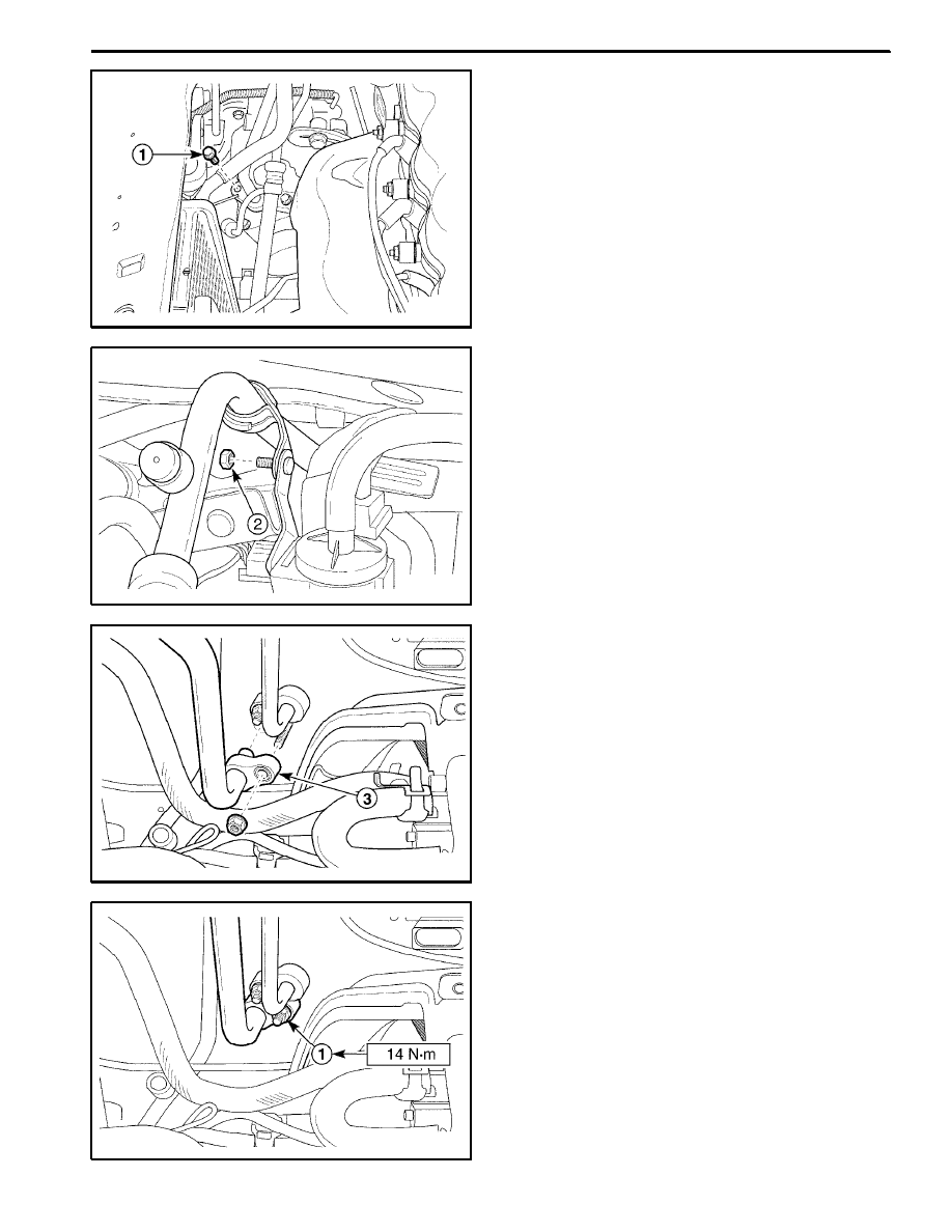
2. Tighten the fittings and the bolt.
Tighten
D
Tighten the condenser pipe--to--compressor pipe
fitting to 23 NSm (17 lb-ft) (1).
D
Tighten the condenser pipe--to--receiver dryer pipe
fitting to 14 NSm (10.5 lb-ft) (2).
3. Evacuate and recharge the system. Refer to “Dis-
charging, Adding Oil, Evacuating, and Charging Pro-
cedures for A/C System” in this section.
4. Install the front bumper fascia. Refer to Section 9O,
Bumpers and Fascias.
5. Connect the negative battery cable.
D108B517
A/C HIGH PRESSURE PIPE LINE
(Left--Hand Drive Shown, Right--Hand
Drive Similar)
Removal Procedure
1. Disconnect the negative battery cable.
2. Remove the front bumper fascia. Refer to Section
9O, Bumpers and Fascias.
3. Discharge and recover the refrigerant. Refer to “Dis-
charging, Adding Oil, Evacuating, and Charging Pro-
cedures for A/C System” in this section.
4. Remove the A/C high pressure pipe line between the
compressor and the condenser.
D
Remove the bolt securing the high pressure pipe
line to the compressor (1).
MANUAL CONTROL HEATING, VENTILATION, AND AIR CONDITIONING SYSTEM 7B -- 23
DAEWOO M-150 BL2
D18B518A
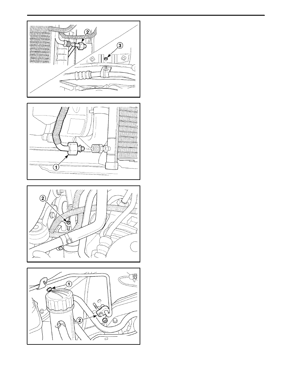
D
Loosen the fitting securing the high pressure pipe
line to the condenser pipe line (2).
D
Remove the clamp nut (3).
D18B519A
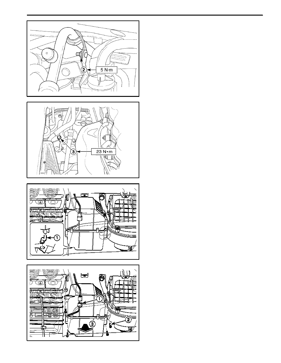
5. Remove the A/C high pressure pipe line between the
condenser and the receiver dryer.
D
Loosen the fitting securing the receiver dryer to the
condenser (1).
D108B520
D
Remove the receiver dryer flange nuts (2).
D18B521A
6. Remove the A/C high pressure pipe line between the
receiver dryer and the evaporator.
D
Remove the purge control valve. Refer to Section
1F, Engine Controls.
D
Remove the bracket nut (1).
D
Loosen the fitting (2).
7B -- 24 MANUAL CONTROL HEATING, VENTILATION, AND AIR CONDITIONING SYSTEM
DAEWOO M-150 BL2
D18B522A
D18B523B
D18B524A
Installation Procedure
Important: Discard the removed O--rings.
1. Install the high pressure pipe lines with the bolts, the
nuts, and the fittings.
Tighten
D
Tighten the bolt securing the high pressure pipe
line to the compressor to 23 NSm (17 lb-ft) (1).
D
Tighten the fitting securing the high pressure pipe
line to the condenser pipe line to 23 NSm (17 lb-ft)
(2).
D
Tighten the fitting securing the high pressure pipe
line to the receiver dryer to 14 NSm (10.5 lb-ft) (3).
D
Tighten the bracket nut to 5 NSm (44 lb-in) (4).
D
Tighten the receiver dryer flange nuts to 14 NSm
(10.5 lb-ft) (5).
D
Tighten the nut securing the high pressure pipe line
to the evaporator to 14 NSm (10.5 lb-ft) (6).
D
Tighten the bracket nut to 5 NSm (44 lb-in) (7).
2. Install the purge control valve. Refer to Section 1F,
Engine controls.
3. Evacuate and recharge the system. Refer to “Dis-
charging, Adding Oil, Evaculating, and Charging Pro-
cedures for A/C System” in this section.
4. Install the front bumper fascia. Refer to Section 9O,
Bumpers and Fascias.
5. Connect the negative battery cable.
D18B525B
MANUAL CONTROL HEATING, VENTILATION, AND AIR CONDITIONING SYSTEM 7B -- 25
DAEWOO M-150 BL2
D108B526
A/C LOW PRESSURE PIPE LINE
(Left--Hand Drive Shown, Right--Hand
Drive Similar)
Removal Procedure
1. Disconnect the negative battery cable.
2. Discharge and recover the refrigerant. Refer to “Dis-
charging, Adding Oil, Evacuating, and Charging Pro-
cedures for A/C System” in this section.
3. Remove the A/C low pressure pipe line.
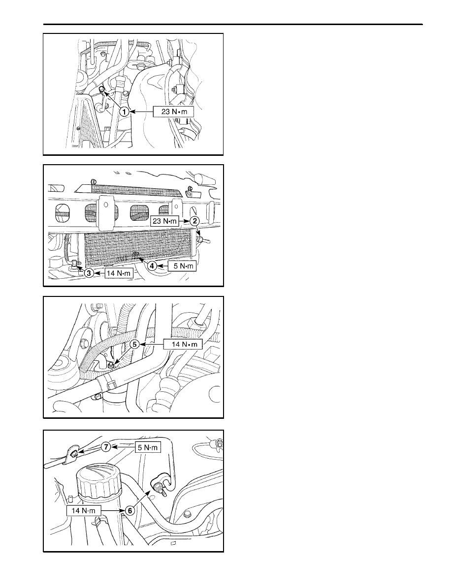
D
Remove the bolt securing the A/C low pressure
pipe line at the compressor (1).
D18B527A
D
Remove the bracket nut from shut bar (2).
D18B528A
D
Remove the purge control valve. Refer to Section
1F, Engine Controls.
D
Loosen the nut securing the A/C low pressure pipe
line at the evaporator (3).
D18B529B
Installation Procedure
Important: Discard the removed O--rings.
1. Install the A/C low pressure pipe line.
Tighten
D
Tighten the nut securing the A/C low pressure pipe
line at the evaporator to 14 NSm (10.5 lb-ft) (1).
7B -- 26 MANUAL CONTROL HEATING, VENTILATION, AND AIR CONDITIONING SYSTEM
DAEWOO M-150 BL2
D18B530B
D18B531A
D
Tighten the bracket nut to 5 NSm (44 lb-in) (2).
D
Tighten the bolt securing the A/C low pressure pipe
line at the compressor to 23 NSm (17 lb-ft) (3).
2. Evacuate and recharge the system. Refer to “Dis-
charging, Adding Oil, Evacuating, and Charging Pro-
cedure for A/C System” in this section.
3. Connect the negative battery cable.
D108B532
D108B533
EVAPORATOR UNIT AND DRAIN
HOSE
(Left--Hand Drive Shown, Right--Hand
Drive Similar)
Removal Procedure
1. Disconnect the negative battery cable.
2. Discharge and recover the refrigerant. Refer to “Dis-
charging, Adding Oil, Evacuating, and Charging Pro-
cedures for A/C System” in this section.
3. Loosen the high pressure pipe line (receiver dry-
er → evaporator) nut and the low pressure pipe line
(evaporator → compressor) nut.
4. Remove the glove box. Refer to Section 9E, Instru-
mentation/Driver information.
5. Remove the evaporator unit.
D
Remove the drain hose (1).
D
Disconnect the thermistor connector (2).
D
Remove the screws (3).
D
Remove the evaporator backward slowly (4).
MANUAL CONTROL HEATING, VENTILATION, AND AIR CONDITIONING SYSTEM 7B -- 27
DAEWOO M-150 BL2
D18B534A
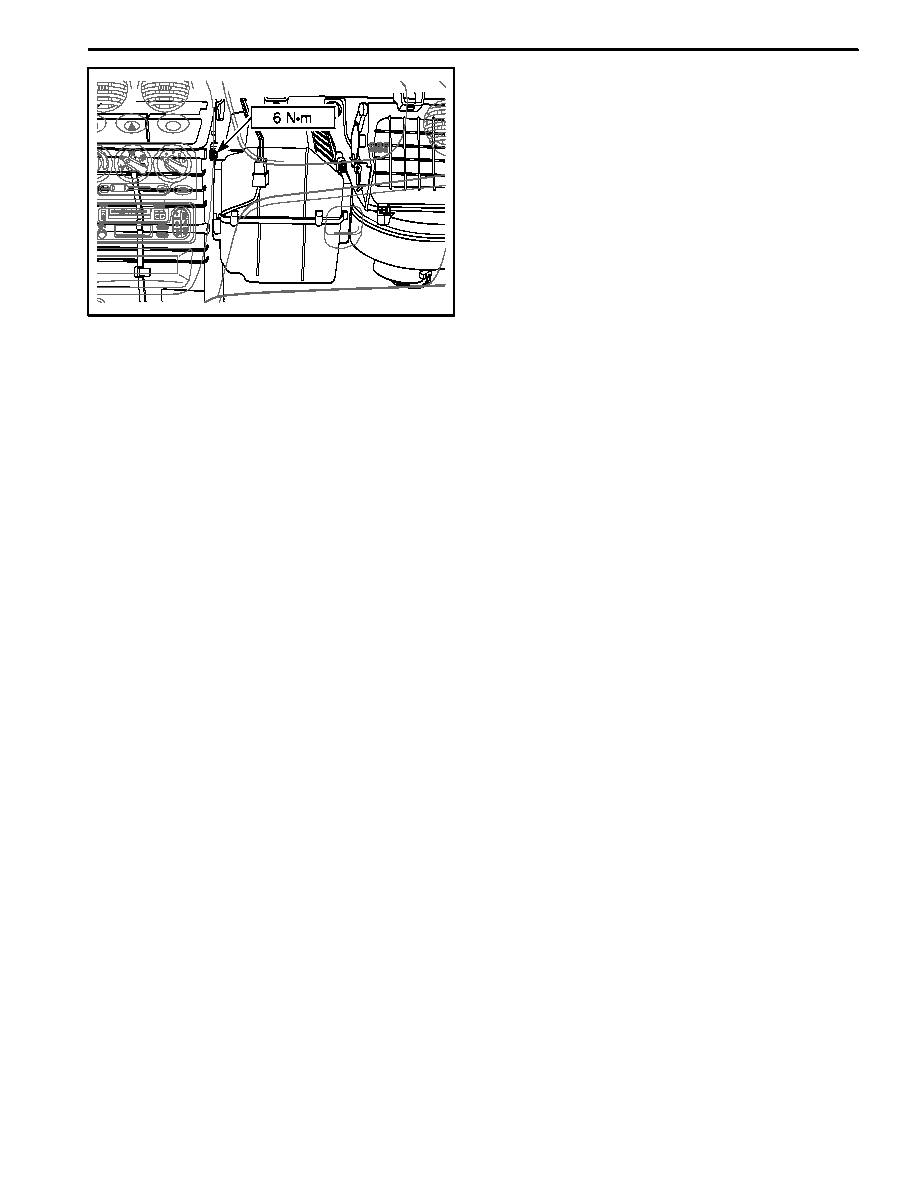
Installation Procedure
1. Install the evaporator evaporator with the screws.
2. Connect the thermistor connector.
3. Install the drain hose.
4. Install the glove box. Refer to Section 9E, Instrumen-
tation / Driver Information.
5. Tighten the high pressure pipe line (receiver dry-
er → evaporator) nut and the low pressure pipe line
(evaporator → compressor) nut to 14 NSm (10.5 lb-ft).
6. Evacuate and recharge the system. Refer to “Dis-
charging, Adding Oil, Evacuating, and Charging Pro-
cedures for A/C System” in this section.
7. Connect the negative battery cable.
7B -- 28 MANUAL CONTROL HEATING, VENTILATION, AND AIR CONDITIONING SYSTEM
DAEWOO M-150 BL2
UNIT REPAIR
D18B701A
EVAPORATOR CORE AND
EXPANSION VALVE
Disassembly Procedure
1. Remove the evaporator unit. Refer to “Evaporator
Unit and Drain Hose” in this section.
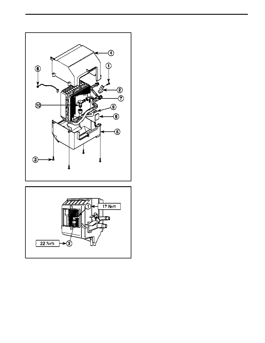
2. Remove the evaporator core and expansion valve.
D
Remove the screw (1).
D
Remove the clamp (2).
D
Remove the screws securing the evaporator case
cover (3).
D
Remove the upper evaporator case cover (4).
D
Remove the lower evaporator case cover (5).
D
Remove the thermistor (6).
D
Loosen the fitting and remove the high pressure
pipe line (7).
D
Remove the tape (8).
D
Remove the evaporator plate seal (9).
D
Loosen the fitting and remove the expansion valve
(10).
D18B702A
Assembly Procedure
1. Install the exponsion valve with the fitting.
Tighten
Tighten the high pressure pipe line coupling to 17 NSm
(13 lb-ft) (1).
2. Install the evaporator plate seal.
3. Install the tape.
4. Install the high pressure pipe line with the fitting.
Tighten
Tighten the expansion valve coupling to 22 NSm (16
lb-ft) (2).
5. Install the thermistor.
6. Install the screws securing the evaporator case cov-
er.
7. Install the clamp and the screw.
8. Install the evaporator unit. Refer to “Evaporator Unit
and Drain Hose” in this section.
MANUAL CONTROL HEATING, VENTILATION, AND AIR CONDITIONING SYSTEM 7B -- 29
DAEWOO M-150 BL2
D10B703A
COMPRESSOR OVERHAUL
Tools Required
DW--610--010 Clutch Hub Holding Tool
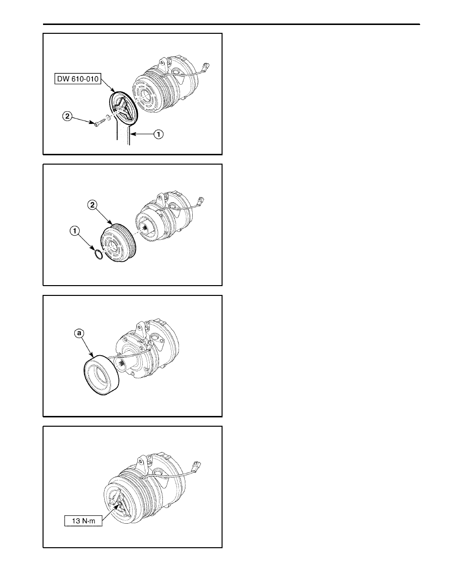
Disassembly Procedure
1.Remove the compressor. Refer to “Compressor” in
this section.
2. Remove the clutch drive plate.
D
Use the clutch hub holding tool DW--610--010 to
keep the clutch drive plate (1).
D
Remove the shaft bolt (2).
D18B704A
3. Remove the compressor pulley.
D
Remove the snap ring using a ring pryer (1).
D
Remove the pulley (2).
D18B705A
4. Disconnect the wiring harness holder and remove the
electromagnetic clutch.
a. Electromagnetic clutch
D18B706B
Assembly Procedure
1. Connect the wiring harness holder and install the
clutch coil.
2. Install the snap ring and compressor pulley.
3. Use the clutch hub holding tool DW--610--010, install
the clutch drive plate with the shaft bolt.
Tighten
Tighten the shaft bolt to 13 NSm (115 lb-in).
4. Install the compressor. Refer to “Compressor” in this
section.
7B -- 30 MANUAL CONTROL HEATING, VENTILATION, AND AIR CONDITIONING SYSTEM
DAEWOO M-150 BL2
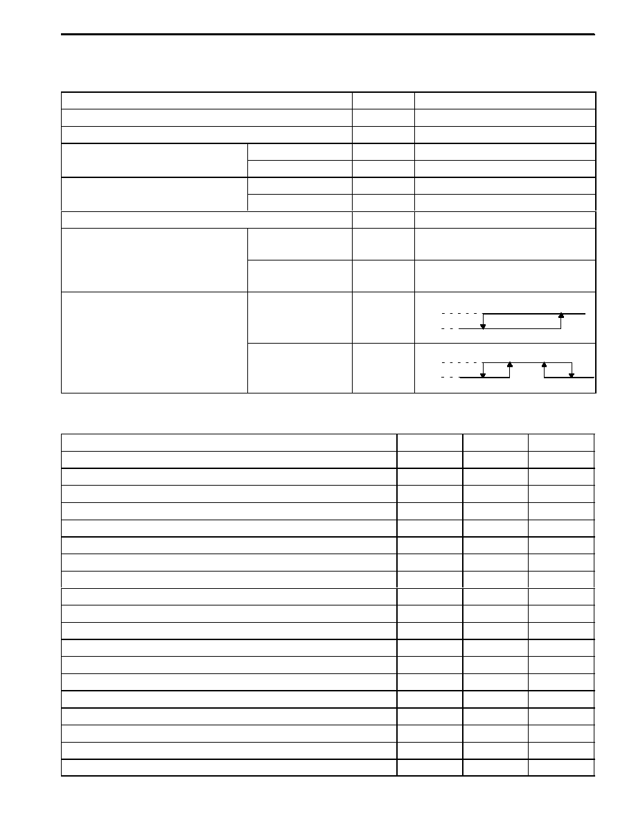
SPECIFICATIONS
GENERAL SPECIFICATIONS
Application
Unit
Description
Compressor
--
SP--10.4PK
Receiver--Dryer
--
AL R/DRIER
Refrigerant
Type
--
R--134a System
Refrigerant
Capacity
g
500 (RHD : 530)
Refrigerant Oil in A/C System
Type
--
RL 244 PAG OIL
Refrigerant Oil in A/C System
Capacity
cc
150
A/C Cooling Capacity (Airflow rate 8.7 kg/min)
Kcal/h
5,500
Refrigerant Pressure in A/C Sys-
tem(Engine Idle, Fresh Air 30_C
(86_F) Ambient Temperature
Low Pressure Side
kPa (psi)
200 (2.9)
(86_F), Ambient Temperature
25_C--35_C (77_F--95_F), Tempera-
ture to Full Cold)
High Pressure Side
kPa (psi)
1,500 (217.5)
A/C Compressor ON/OFF Condition
(Refer to Section 1F, Engine Controls
About the A/C Compressor ON/OFF
Evaporator Therm-
istor Temperature
_
C (_F)
2.45(36.81)
1.0 (34.2)
ON
OFF
About the A/C Compressor ON/OFF
Condition According to Engine Oper-
ating Status)
Dual Cut Switch
Pressure
kPa
205--245
180--220
ON
OFF
300--400
240--280
FASTENER TIGHTENING SPECIFICATIONS
Application
NSm
Lb-Ft
Lb-In
Compressor Upper Bracket Bolts
20
15
--
Compressor Front Head-to-Rear Head Through-Bolt
22
16
--
High Pressure Pipe Line (Compressor → Condenser) Bolt
23
17
--
High Pressure Pipe Line (Compressor → Condenser) Fitting
23
17
--
High Pressure Pipe Line (Compressor → Condenser) Clamp Nut
5
--
44
Receiver--Dryer Flange Nut
14
10.5
--
High Pressure Pipe Line (Condenser → Receiver--Dryer) Fitting Nut
14
10.5
--
High Pressure Pipe Line (Receiver--Dryer → Evaporator) Fitting Nut
14
10.5
--
High Pressure Pipe Line(Receiver--Dryer → Evaporator) Clamp Nut
5
--
44
Low Pressure Pipe Line (Evaporator → Compressor) Fitting Nut
14
10.5
--
Low Pressure Pipe Line (Evaporator → Compressor) Clamp Nut
5
--
44
Low Pressure Pipe Line(Evaporator→Compressor) Compressor Bolt
23
17
--
Dual Cut Switch
13
--
115
Receive--Dryer Bracket--to--Body Bolts
5
--
44
Receive--Dryer Bracket Bolt
5
--
44
Expansion Valve Coupling (Receiver--Dryer → Expansion Valve)
17
13
--
Expansion Valve Coupling (Expansion Valve → Evaporator)
22
16
--
Compressor Shaft Bolt
13
--
115
Condenser Mounting Nuts
4
--
36
MANUAL CONTROL HEATING, VENTILATION, AND AIR CONDITIONING SYSTEM 7B -- 31
DAEWOO M-150 BL2
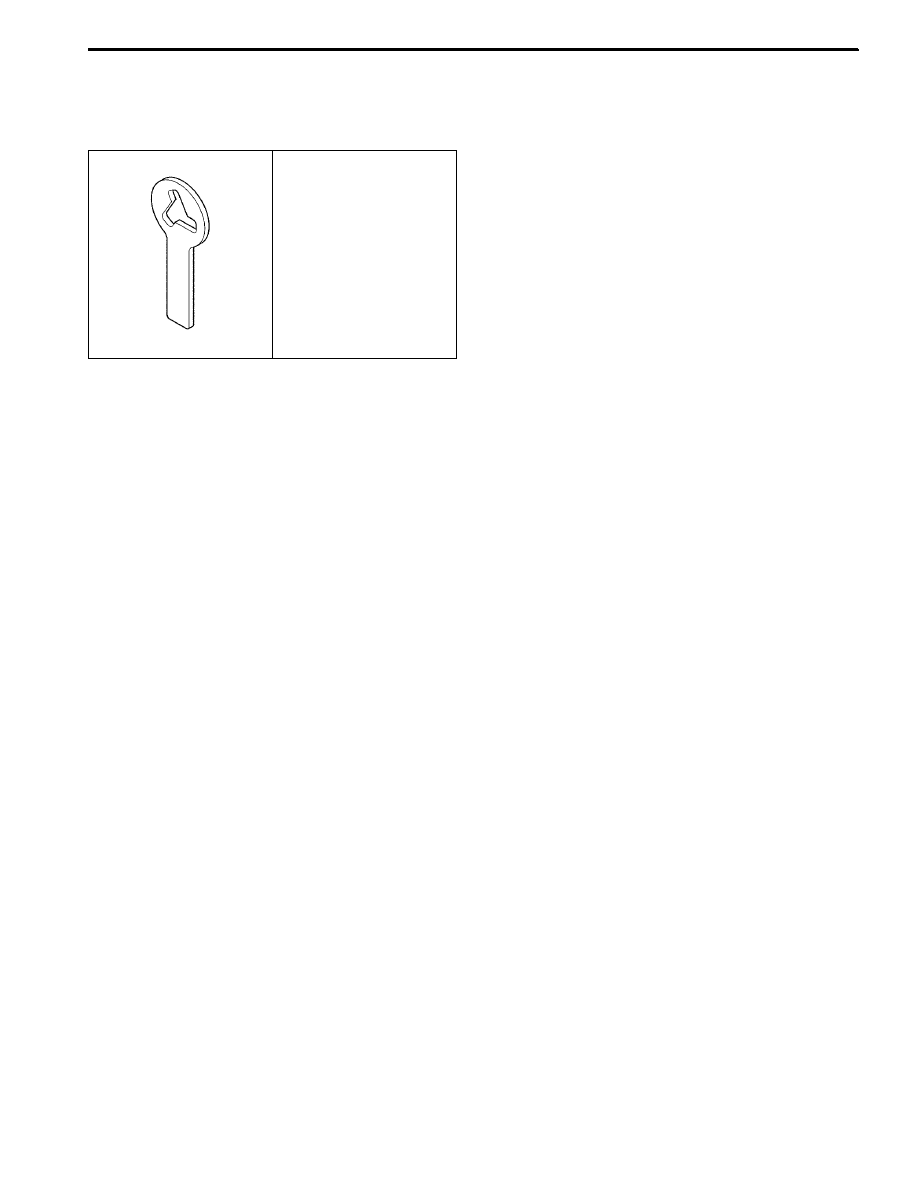
SPECIAL TOOLS AND EQUIPMENT
SPECIAL TOOLS TABLE
D108B101
DW--610--010
Clutch Hub
Holding Tool
7B -- 32 MANUAL CONTROL HEATING, VENTILATION, AND AIR CONDITIONING SYSTEM
DAEWOO M-150 BL2
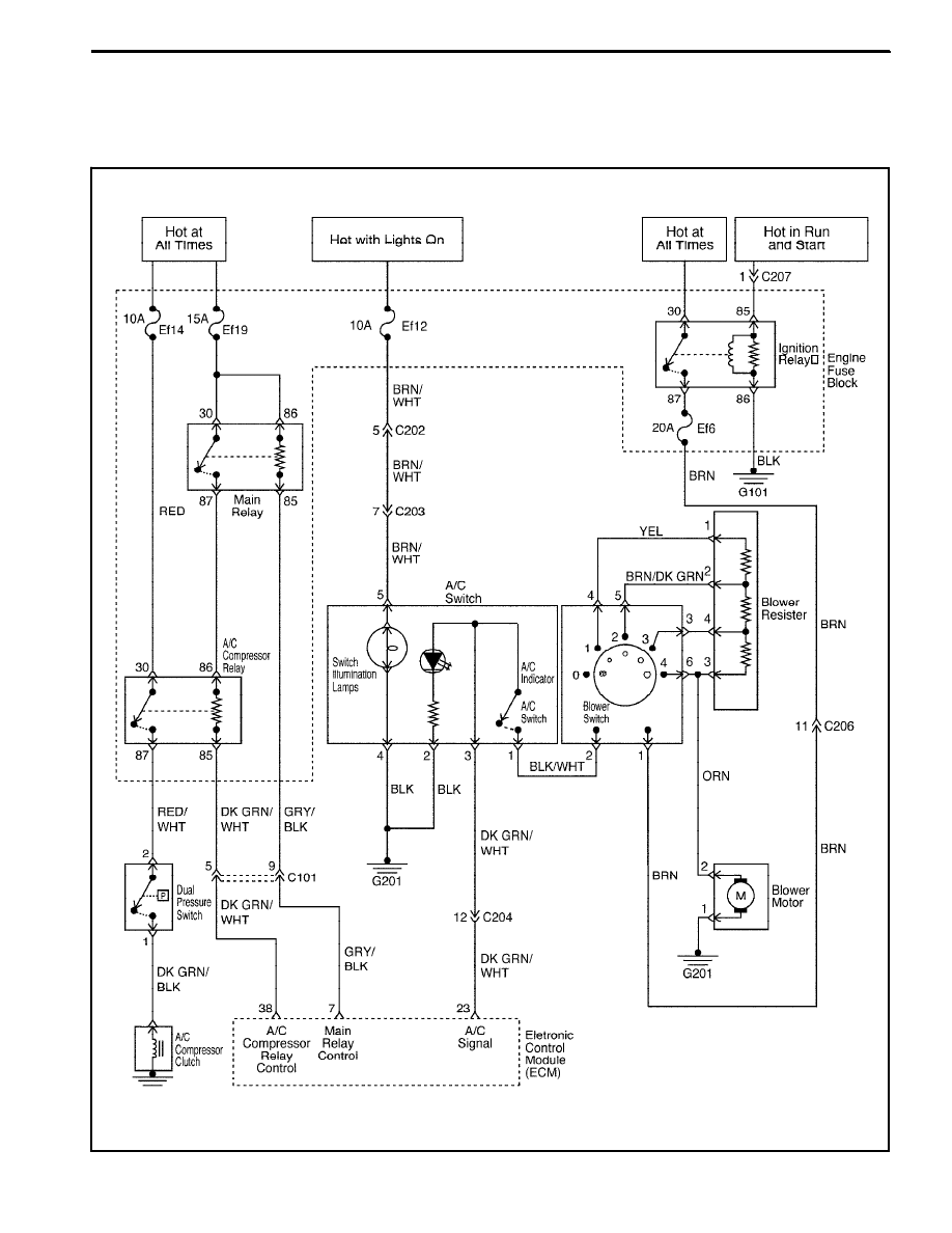
SCHEMATIC AND ROUTING DIAGRAMS
A/C DIAGRAMS
D18B201B
MANUAL CONTROL HEATING, VENTILATION, AND AIR CONDITIONING SYSTEM 7B -- 33
DAEWOO M-150 BL2
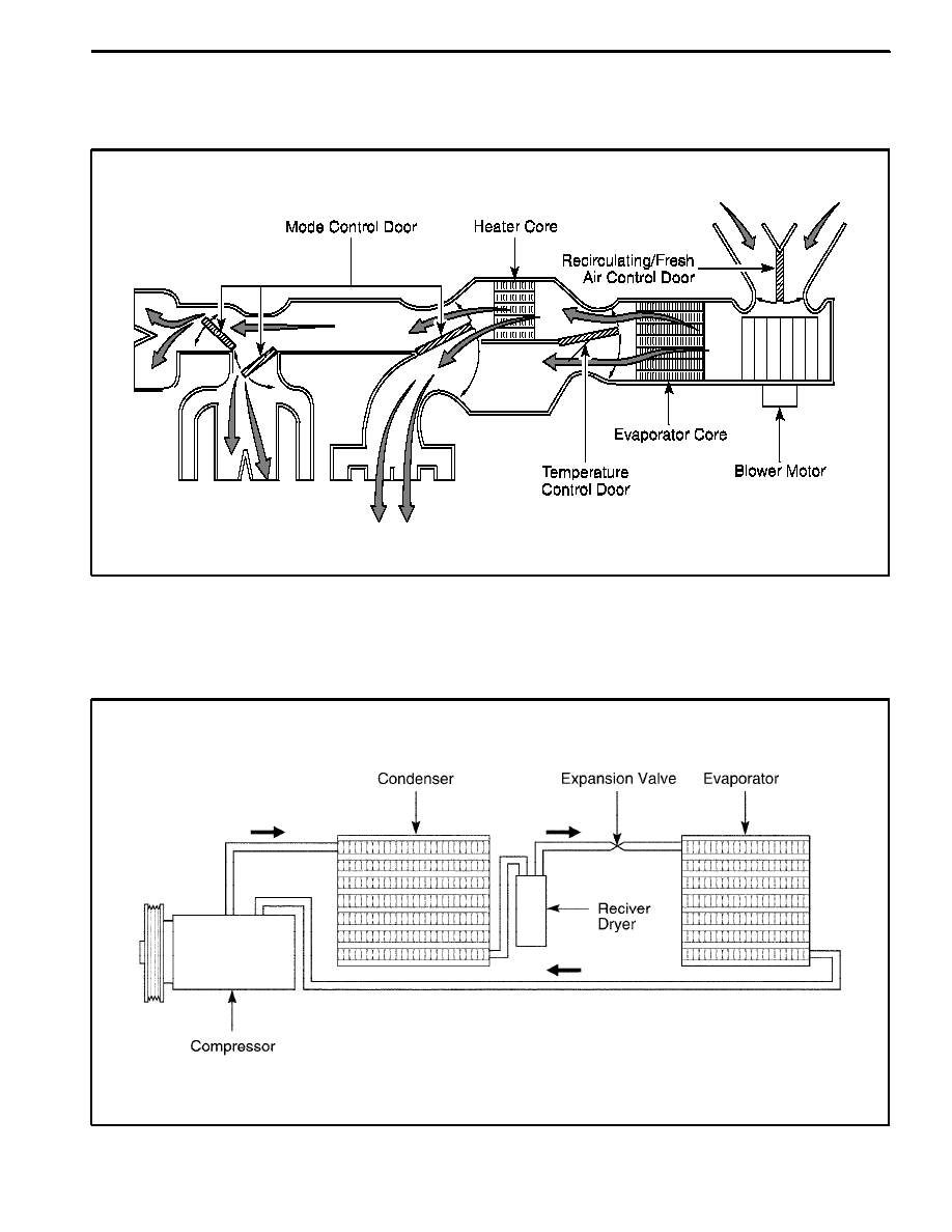
A/C AIRFLOW
(Left--Hand Drive Shown, Right--Hand Drive Similar)
D108B202
A/C SYSTEM
(Left--Hand Drive Shown, Right--Hand Drive Similar)
D18B203A
Wyszukiwarka
Podobne podstrony:
M37b1 Heating, Ventilation and AC 1 20
Removal and installation of interior temperature sensor Heating, ventilation Model 126 A To 06 81,
VENTILATION AND COOLING IN UNDERGROUND MINES (2)
VENTILATION AND COOLING IN UNDERGROUND MINES
Mine ventilation and air (2)
Fundamentals of Anatomy and Physiology 21 Chapter
Norris, C E i Colman, A M (1993) Context effects on memory for televiosion advertisements Social Bah
8381 Replacing dust filter for heating & ventilation
M37a2 Heating and Ventilation System 18 32
M37a1 Heating and Ventilation System 1 17
Basic AC Generators and Motors
21 269 287 Effect of Niobium and Vanadium as an Alloying Elements in Tool Steels
więcej podobnych podstron