
Lab 04
MAGNETICALL COUPLED CIRCUITS
Goal: To study the electric signal transmission between two resonance circuits
coupled magnetically.
Experiment
1. Two resonance circuits magnetically coupled.
1.1 Build the circuit of Fig. 1.
1.2 Measure capacitor voltages U
C1
and U
C2
as a function of frequency of
the constant current in the primary circuit. The constancy of this current
should be maintain by kipping the generator output voltage U
G
constant
and using sufficiently large impedance Z in series with the powered
circuit. This allows to replace the total impedance by the impedance Z
and gat the constant current as:
i = U
G
/Z
The measurements should be performed for: i) over-critical coupling, ii)
critical coupling and iii) weak, below critical, coupling.
2. Resonance and damped circuits.
2.1 Build the circuit of Fig. 2.
2.2 Measure capacitor voltages U
C1
as a function of frequency of the
constant current in the primary circuit. Measurements should be
performed for three different values of the impedance R
Z
; about 10Ω,
100Ω and one much larger value.
3. Background
3.1 Inductance, capacitance and resistance in AC circuits.
3.2 Electrical resonance circuits (series, parallel). Magnetic coupling.
3.3 Coupled circuits and transmission of electrical signals.
Pre-lab reading
[1] I. Mayergoyz, W. Lawson,
Basic Electric Circuit Theory.
[2] W.H. Hayt,
Engineering Circuit Analysis.
[3] W.H. Hayt, J.E. Kemmerly,
Engineering Circuit Analysis.
[4] S. Szczeniowski
Fizyka. Tom III. (Elektryczno
i magnetyzm).
ść
[5] T. Szczypułowski
Podstawy elektroniki.
[6] I.P. Żerebcow
Radiotechnika.
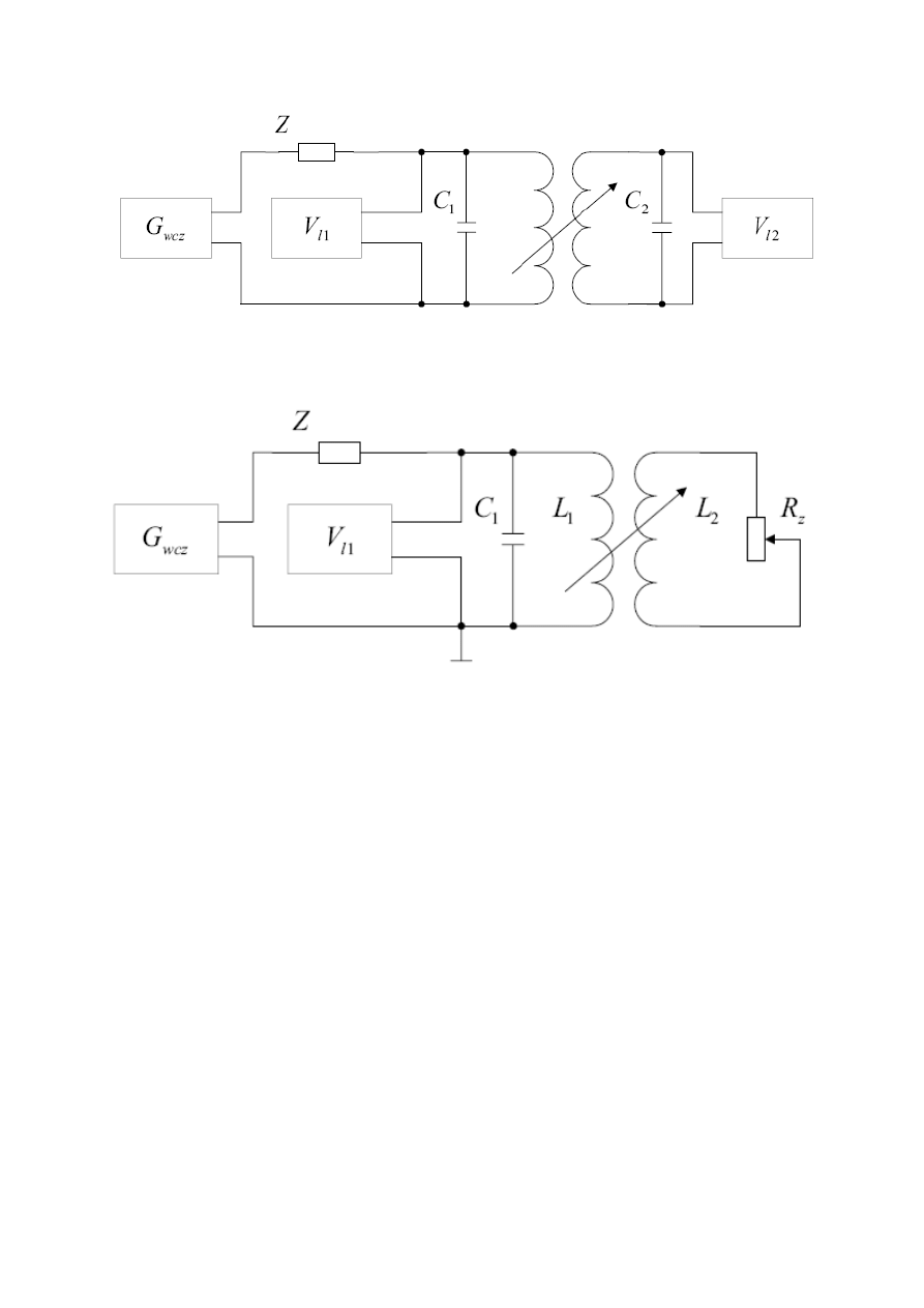
Fig 1: Magneticalle coupled resonance circuits with HF generator and voltmeters.
_
G
wcz
– High frequency generator,
V
l1
and
V
l2
– high frequency voltmeters (bulb voltmeters).
Fig 2: Magnetically coupled resonance circuit magnetically coupled to damped circuit with HF
generator and voltmeter.
_
G
wcz
– High frequency generator,
V
l1
– high frequency voltmeter (bulb voltmeter).
Wyszukiwarka
Podobne podstrony:
5396
5396
5396
5396
5396
newspaper 5396
więcej podobnych podstron