
CL-1
CLUTCH
C TRANSMISSION/TRANSAXLE
CONTENTS
D
E
F
G
H
I
J
K
L
M
SECTION
CL
A
B
CL
CLUTCH
APPLICATION NOTICE .............................................. 2
How to Check Vehicle Type ..................................... 2
PRECAUTIONS .......................................................... 3
Caution ..................................................................... 3
PREPARATION ........................................................... 4
Special Service Tools ............................................... 4
NVH Troubleshooting Chart ..................................... 5
CLUTCH ................................................................ 5
CLUTCH PEDAL ........................................................ 6
On Board Inspection ................................................ 6
Removal and Installation .......................................... 7
CLUTCH FLUID .......................................................... 8
Air Bleeding Procedure ............................................ 8
CLUTCH MASTER CYLINDER .................................. 9
Removal and Installation .......................................... 9
CSC (CONCENTRIC SLAVE CYLINDER) ................ 10
Removal and Installation ........................................ 10
CLUTCH DISC, CLUTCH COVER AND FLYWHEEL... 11
Removal and Installation ........................................ 11
REMOVAL ........................................................... 12
INSPECTION AND ADJUSTMENT AFTER
REMOVAL (CR ENGINE) .................................... 12
INSPECTION AND ADJUSTMENT AFTER
REMOVAL (K9K ENGINE) .................................. 13
INSTALLATION ................................................... 13

CL-2
APPLICATION NOTICE
APPLICATION NOTICE
PFP:00000
How to Check Vehicle Type
BCS000KL
Confirm K9K engine type with Model written on identification plate (refer to
),then refer to service information in CL section.
Vehicle type
Engine type
xTKxxxxE11xxE
50kW
xTKxxxxE11xxA
63kW

PRECAUTIONS
CL-3
D
E
F
G
H
I
J
K
L
M
A
B
CL
PRECAUTIONS
PFP:00001
Caution
BCS000KM
●
Recommended fluid is brake fluid “Nissan Genuine Brake Fluid or DOT 3 or DOT 4 (US FMVSS
No.116)". Refer to
MA-24, "Fluids and Lubricants"
●
Never reuse drained brake fluid.
●
Be careful not to splash brake fluid on painted areas.
●
Use new brake fluid to clean or wash all parts of master cylinder and concentric slave cylinder.
●
Never use mineral oils such as gasoline or kerosene. It will ruin the rubber parts of the hydraulic
system.
●
If manual transaxle is removed from the vehicle, always replace CSC (concentric slave cylinder).
CSC insert is returned to original position to remove transaxle. Dust on clutch disc sliding parts
may damage CSC seal and may cause fluid leak.
●
Do not disassemble master cylinder and CSC.
WARNING:
After cleaning clutch disc, wipe it with a dust collector. Do not use compressed air.
CL-4
PREPARATION
PREPARATION
PFP:00002
Special Service Tools
BCS000KN
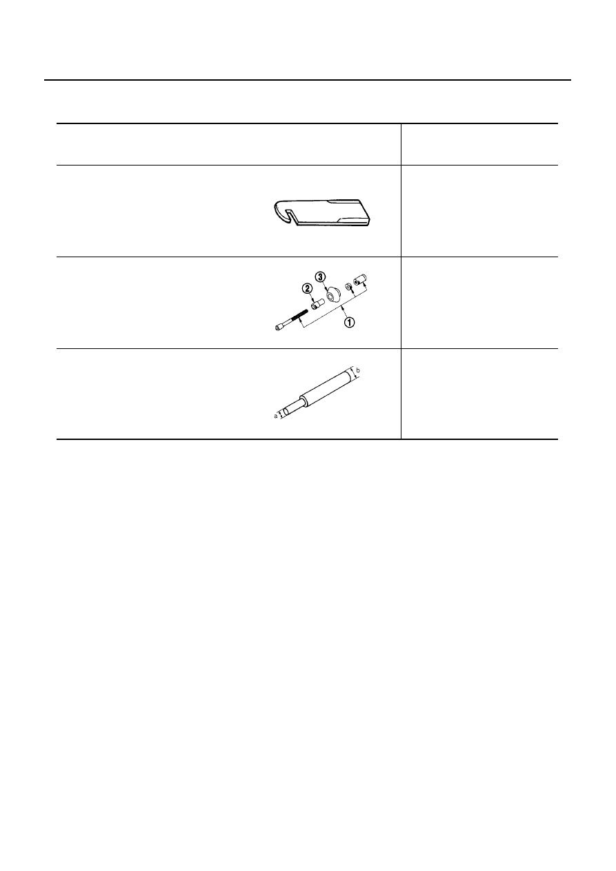
Tool number
(Renault tool number)
Tool name
Description
ST20050240
Diaphragm spring adjusting wrench
Inspecting diaphragm spring of
clutch cover
EM07020000
Clutch aligner
Installing clutch cover and disc
KV30101000
Clutch aligner
a:15.9mm(0.626in)dia
b:19.8mm(0.780in)dia
Installing clutch disc
ZZA0508D
PCIB0017E
ZZA1178D
NOISE, VIBRATION AND HARSHNESS (NVH) TROUBLESHOOTING
CL-5
D
E
F
G
H
I
J
K
L
M
A
B
CL
NOISE, VIBRATION AND HARSHNESS (NVH) TROUBLESHOOTING
PFP:00003
NVH Troubleshooting Chart
BCS000KO
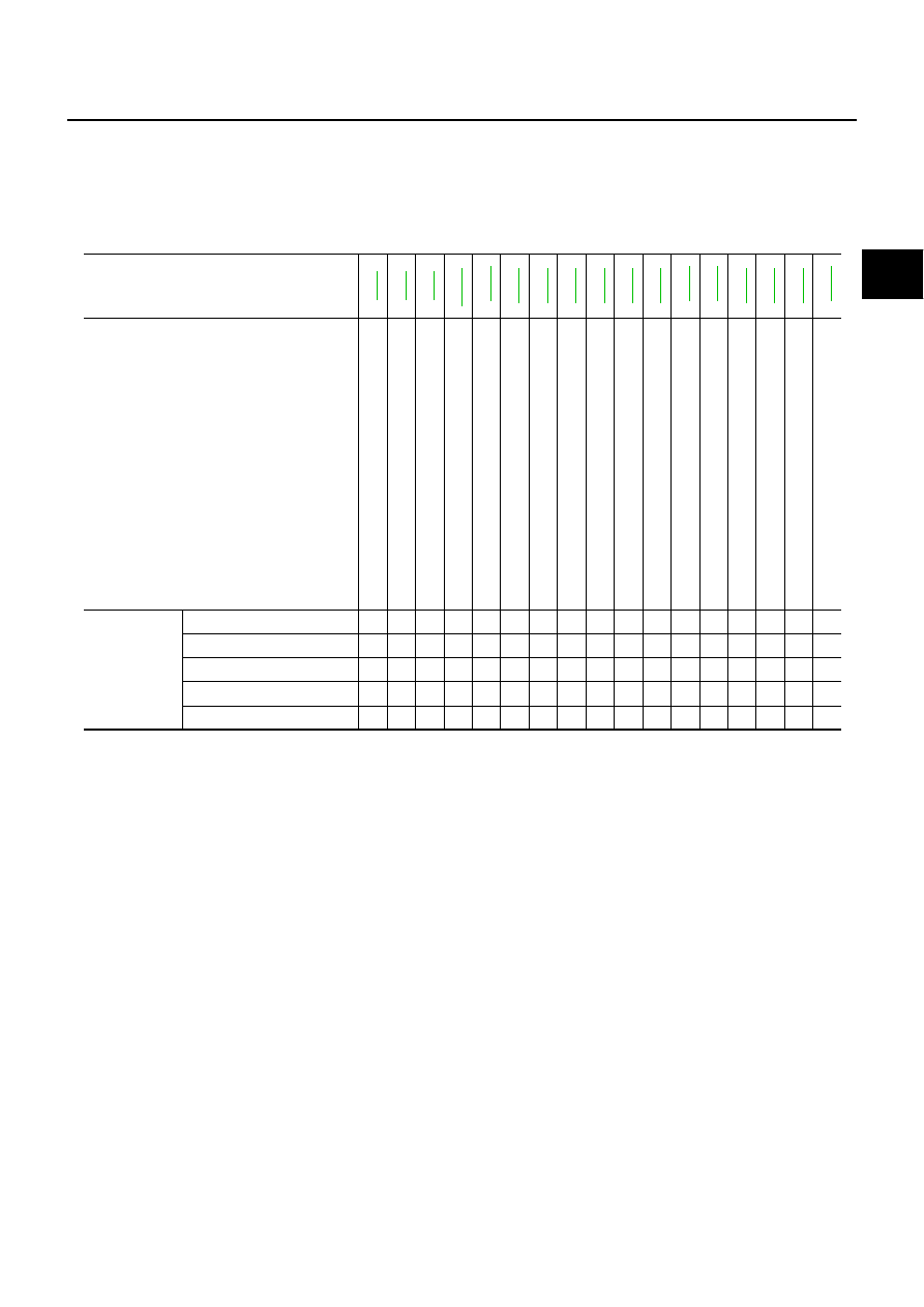
Use the chart below to help you find the cause of the symptom. The numbers indicate the order of the inspec-
tion. If necessary, repair or replace these parts.
CLUTCH
Reference page
.
.
.
.
.
.
.
.
.
.
.
.
.
SUSPECTED PARTS (Possible cause)
CL
UTCH
PEDAL
(F
re
e
p
la
y
o
u
t
o
f
a
d
ju
s
tme
n
t)
CL
UTCH
L
INE
(Ai
r
in
lin
e
)
M
ASTER
C
Y
LI
N
D
E
R
P
IS
T
O
N
C
U
P
(D
am
ag
ed)
ENGI
NE
MOUNTI
N
G
(L
o
o
s
e
)
RELEASE
BEARING
(W
o
rn
,
d
ir
ty
o
r
dam
age
d)
CL
UTCH
DI
SC
(O
u
t
o
f
tr
u
e
)
C
L
U
T
C
H
D
ISC
(R
u
nout
is
ex
cess
iv
e)
CL
UTCH
DI
SC
(L
in
in
g
b
ro
k
e
n
)
CL
UTCH
DI
SC
(Dir
ty
o
r
b
u
rn
e
d
)
CL
UTCH
DI
SC
(O
ily
)
CL
UTCH
DI
SC
(W
o
rn
o
u
t)
C
L
U
T
C
H
D
ISC
(H
a
rde
ned)
CL
UTCH
DI
SC
(L
a
c
k
o
f
s
p
lin
e
g
re
a
s
e
)
D
IAP
H
R
A
G
M
SPR
IN
G
(D
a
m
aged)
D
IA
P
H
R
A
G
M
S
P
R
IN
G(
O
u
to
ft
ip
a
lig
n
m
e
n
t)
PRESSURE
PLA
T
E
(Distor
tion)
FL
YW
HEEL
(Distor
tion)
Symptom
Clutch grabs/chatters
1
2
2
2
2
2
Clutch pedal spongy
1
2
Clutch noisy
1
Clutch slips
1
2
2
3
4
5
Clutch does not disengage
1
2
3
4
4
4
4
4
4
5
5
6
CL-6
CLUTCH PEDAL
CLUTCH PEDAL
PFP:46540
On Board Inspection
BCS000KP
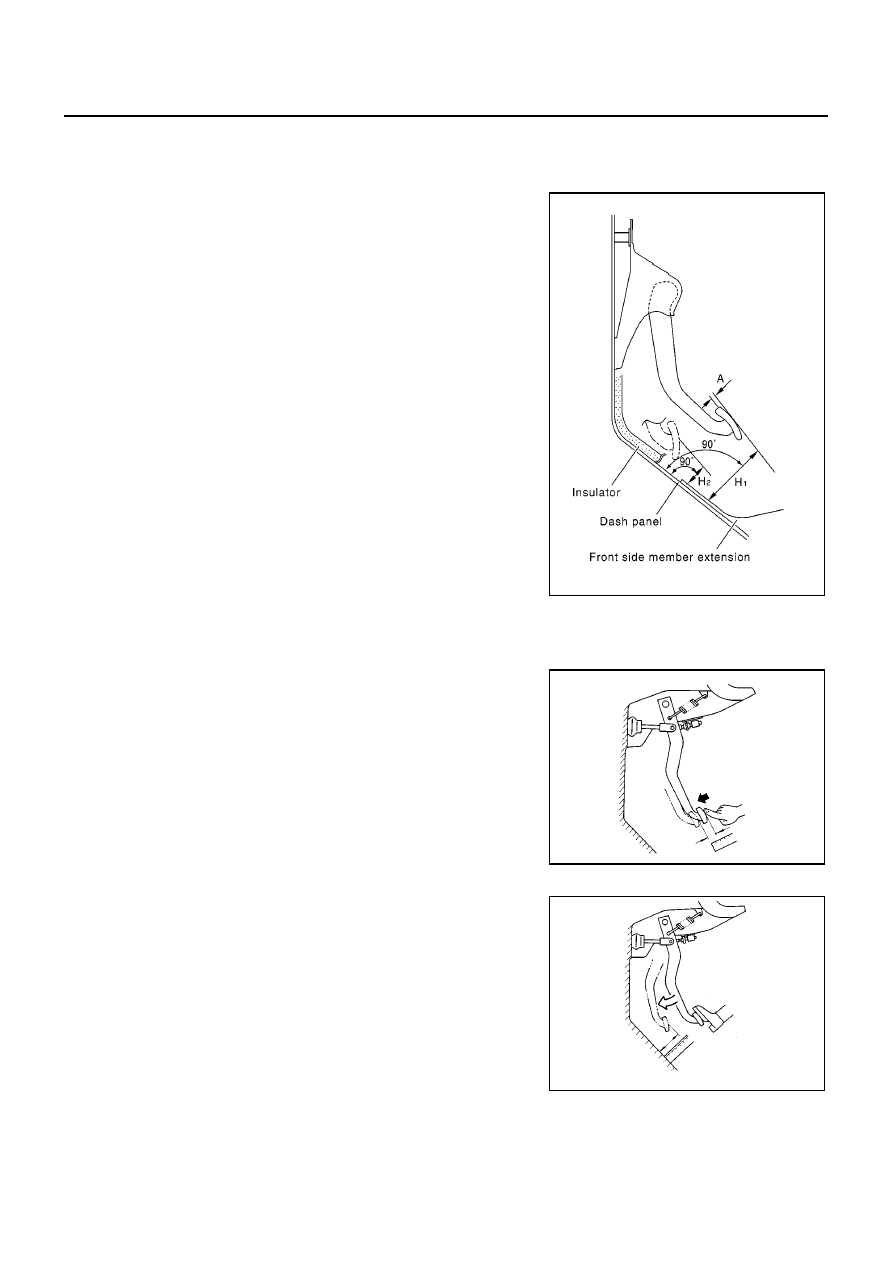
HEIGHT INSPECTION
1.
Make sure clutch pedal height H
1
from upper surface of the
dash panel is within the specified range.
2.
If pedal height H
1
is outside the specification, replace pedal
assembly.
3.
Make sure free play A at pedal pad top surface and pedal height
H
2
when clutch is disengaged are within the ranges specified
below.
4.
If free play A at pedal pad top surface and pedal height H
2
when
clutch is disengaged are outside the specification, replace clutch pedal assembly.
PLAY INSPECTION
●
Press the clutch pedal by hand until certain resistance can be
felt. Using a scale, Make sure the free play is within the specified
range.
CLEARANCE CHECK
1.
Start the engine and let it idle.
2.
Apply parking brake.
3.
Depress the brake pedal.
4.
Fully depress clutch pedal and shift to 1st gear.
5.
Release clutch pedal gradually. Using a scale, check the clear-
ance between the clutch pedal and floor panel to see if it is
within the specified range.
NOTE:
Pedal height at clutch disengagement varies slightly from the clutch engagement point. Despite this, pedal
height at clutch engagement is commonly used for both cases in order to simplify the inspection.
Pedal height H
1
: 160 - 169 mm (6.30 - 6.65 in)
(LHD with CR engine)
(LHD with HR engine)
: 164 - 174 mm (6.46 - 6.85 in)
(RHD with CR engine)
: 170 - 180 mm (6.69 - 7.09 in)
(LHD K9K 50/63 kW)
: 175 - 185 mm (6.89 - 7.23 in)
(RHD K9K 50/63 kW)
(RHD with HR engine)
A: Pedal free play at the pedal pad
: 0.5 mm (0.02 in)
Pedal height H
2
when clutch is disengaged
: 100 mm (3.94 in) or more (CR engine)
SCIA1256E
Pedal free play
: 0.5 mm (0.02 in)
MAA0023D
Pedal height when the clutch disengages
: 100 mm (3.94 in) or more (CR engine)
MAA0024D
CLUTCH PEDAL
CL-7
D
E
F
G
H
I
J
K
L
M
A
B
CL
Removal and Installation
BCS000KQ
REMOVAL
1.
Remove instrument panel under tray. Refer to
IP-4, "INSTRUMENT PANEL ASSEMBLY"
.
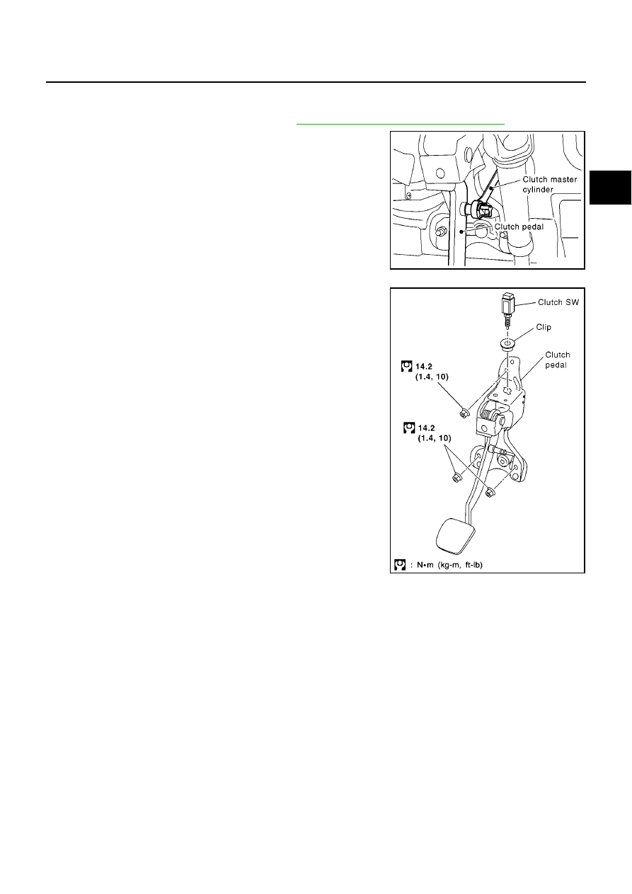
2.
Unlock master cylinder rod end and separate master cylinder
from clutch pedal.
3.
Remove clutch switch harness clamp from pedal bracket.
4.
Disconnect clutch switch connector.
5.
Remove nuts (3), and remove clutch pedal assembly.
INSPECTION AFTER REMOVAL
●
Check clutch pedal for bend, damage, and a cracked weld. If bend, damage, or a cracked weld is found,
replace clutch pedal assembly.
INSTALLATION
●
Install in the reverse order of removal.
SCIA1284E
SCIA1260E
CL-8
CLUTCH FLUID
CLUTCH FLUID
PFP:00017
Air Bleeding Procedure
BCS000KR
CAUTION:
●
Monitor fluid level in the reservoir tank to make sure it does not empty.
●
Do not spill brake fluid onto painted surfaces. If it spills, wipe up immediately and wash the
affected area with water.
●
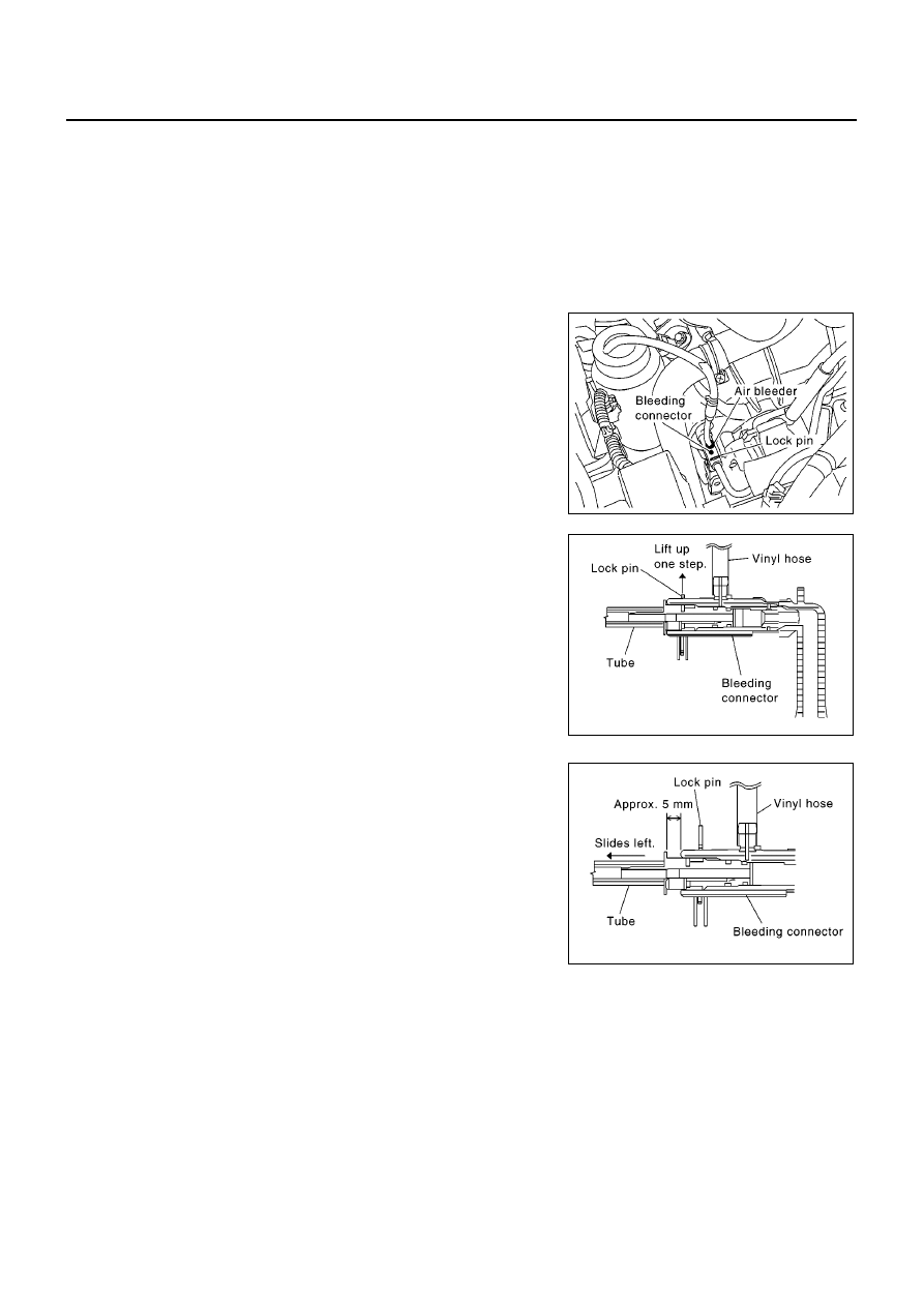
Bleed the bleeding connector.
1.
Fill the master cylinder reservoir tank with new brake fluid.
2.
Remove rubber cap and connect a transparent vinyl hose to air
bleeder of bleeding connector.
3.
Lift tube side lock pin of bleeding connector up one step.
CAUTION:
Do not remove lock pin.
4.
“Depress” and “release” the clutch pedal slowly and fully 15
times at an interval of 2 to 3 seconds and hold it.
CAUTION:
Hold it to prevent releasing tube from bleeding connector
when fluid pressure is applied in the tube.
5.
Slide tube 5 mm (0.20 in) to the direction shown by the arrow
and drain clutch fluid.
6.
Return tube to its original position.
7.
Release clutch pedal and wait for 5 seconds.
8.
Repeat steps 4 to 7 until no bubbles can be observed in the
brake fluid.
SCIA1261E
SCIA1262E
SCIA1263E
CLUTCH MASTER CYLINDER
CL-9
D
E
F
G
H
I
J
K
L
M
A
B
CL
CLUTCH MASTER CYLINDER
PFP:30610
Removal and Installation
BCS000KS
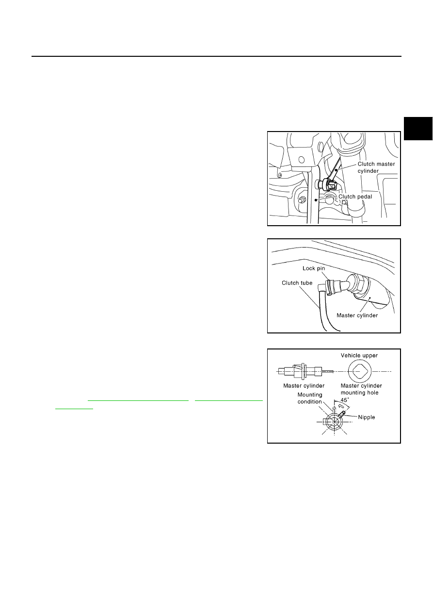
REMOVAL
1.
Drain brake fluid from reservoir tank and remove hose from the nipple.
CAUTION:
Do not spill brake fluid onto painted surfaces. If it spills, wipe up immediately and wash the
affected area with water.
2.
Unlock master cylinder rod end in the passenger room and sep-
arate master cylinder from clutch pedal.
3.
Remove lock pin from master cylinder and separate clutch tube.
4.
Rotate master cylinder clockwise by 45
°
and remove it from the
vehicle.
INSTALLATION
1.
Tilt master cylinder clockwise by 45
°
and insert to the mounting
hole. Rotate counter clockwise and secure it. At this time, nipple
is upward of the vehicle.
2.
After finishing work, perform clutch pedal height inspection and
clutch piping air bleeding.
●
Refer to
,
SCIA1284E
SCIA1285E
SCIA1286E
CL-10
CSC (CONCENTRIC SLAVE CYLINDER)
CSC (CONCENTRIC SLAVE CYLINDER)
PFP:30500
Removal and Installation
BCS000KT
CAUTION:
●
Do not spill brake fluid onto painted surfaces.
If it spills, wipe up immediately and wash the affected area with water.
●
If manual transaxle is removed from the vehicle, always replace CSC (concentric slave cylinder).
CSC insert is returned to original position to remove transaxle. Dust on clutch disc sliding parts
may damage CSC seal and may cause brake fluid leak.
REMOVAL
1.
Remove manual transaxle. Refer to
MT-7, "REMOVAL AND INSTALLATION"
(JH3) or
(JR5).
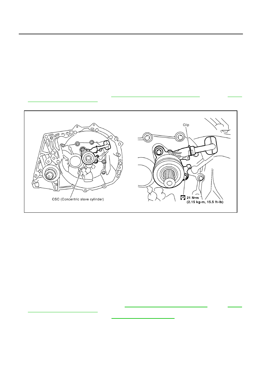
2.
Remove bolts and CSC from manual transaxle.
INSPECTION
NOTE:
●
Cannot disassemble CSC and release bearing because they are integral parts. Replace them as an
assembly.
Inspect for the following, and replace parts if necessary.
●
CSC: damage, foreign material, wear or pinholes on the cylinder outer surface.
●
Release bearing: damage, incorrect rotation direction, or has poor aligning function, and dust seal is
deformed or cracked.
INSTALLATION
1.
Install new CSC to manual transaxle. Tighten to the specified torque.
CAUTION:
Do not insert and operate CSC because piston and stopper of CSC components may fall off.
2.
Install manual transaxle to the vehicle. Refer to
MT-7, "REMOVAL AND INSTALLATION"
(JH3) or
(JR5).
3.
Bleed air from the clutch piping. Refer to
CL-8, "Air Bleeding Procedure"
.
MCIA0172E
Tightening torque
: 21 N·m (2.15 kg-m, 15.5 ft- lb)
CLUTCH DISC, CLUTCH COVER AND FLYWHEEL
CL-11
D
E
F
G
H
I
J
K
L
M
A
B
CL
CLUTCH DISC, CLUTCH COVER AND FLYWHEEL
PFP:30100
Removal and Installation
BCS000KU
CAUTION:
●
If manual transaxle is removed from the vehicle, always replace CSC (concentric slave cylinder).
CSC insert is returned to original position to remove transaxle. Dust on clutch disc sliding parts
may damage CSC seal and may cause brake fluid leak.
●
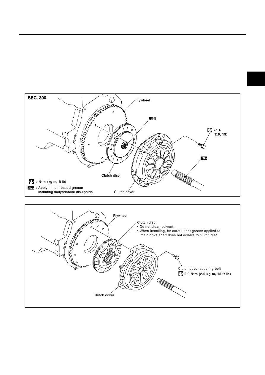
Be careful not to bring any grease into contact with the clutch disc facing, pressure plate surface,
or flywheel surface.
Petrol Engine
Diesel Engine
SCIA1268E
YCL032
CL-12
CLUTCH DISC, CLUTCH COVER AND FLYWHEEL
REMOVAL
1.
Remove manual transaxle from the vehicle. Refer to
MT-7, "REMOVAL AND INSTALLATION"
(JH3) or
MT-37, "REMOVAL AND INSTALLATION"
(JR5).
2.
Loosen clutch cover mounting bolts evenly. Remove clutch cover and clutch disc.
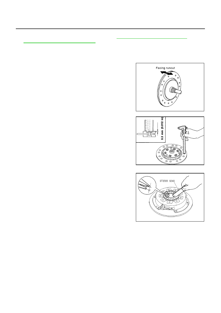
INSPECTION AND ADJUSTMENT AFTER REMOVAL (CR ENGINE)
Clutch Disc
●
Measure circumferential runout relative to the clutch disc center
spline. If it is outside the specification, replace the clutch disc.
●
Using calipers, measure the depth to the clutch disc facing rivet
heads. If it exceeds the allowable wear limit, replace the clutch
disc.
Clutch Cover
Check diaphragm spring lever claws for unevenness with the lever
still on the vehicle. If they exceed the tolerance, adjust lever height
using a diaphragm adjusting wrench (SST).
●
Check clutch cover thrust ring for wear or breakage. If wear or
breakage is found, replace clutch cover assembly.
NOTE:
●
Worn thrust ring will generate a beating noise when tapped at the rivet with a hammer.
●
Broken thrust ring will make a clinking sound when cover is shaken up and down.
●
If a trace of burn or discoloration is found on the clutch cover pressure plate to clutch disc contact surface,
repair the surface with sandpaper. If surface is damaged or distorted, replace the assembly.
Runout limit/diameter of the area to be measured:
CR14 engine
:1.0mm (0.039 in) or less/180
(7.08 in) mm dia.
HR engine
:1.0mm (0.039 in) or less/190
(7.48 in) mm dia.
SCIA1270E
Facing wear limit (depth to the rivet head)
: 0.3 mm (0.012 in)
SCL229
Tolerance for diaphragm spring lever unevenness
CR engine
: 0.7 mm (0.028 in)
HR engine
: 0.7 mm (0.028 in)
K9K 50/63kW
: 0.8 mm (0.031 in)
CLA0069D
CLUTCH DISC, CLUTCH COVER AND FLYWHEEL
CL-13
D
E
F
G
H
I
J
K
L
M
A
B
CL
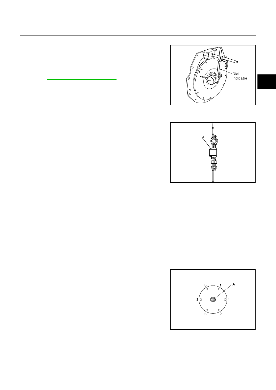
Flywheel Runout
Using a dial gauge, measure runout at the flywheel clutch contact
surface. If runout is outside the specification, replace the flywheel. If
a trace of burn or discoloration is found on the surface, repair it with
sandpaper.
CAUTION:
Measure it at flywheel outer face (not on knock pin and clutch
cover mounting hole).
INSPECTION AND ADJUSTMENT AFTER REMOVAL (K9K ENGINE)
Clutch Disc
●
The hubs of the clutch discs are nickel plated to improve their
sliding performance.
●
Clean the splines of the clutch shaft and install the assembly
without lubricant.
●
Degrease the friction face of the flywheel.
●
Install the clutch disc (offset (A) from the hub on the flywheel
side).
CAUTION:
Reworking on the clutch face is not permitted.
Flywheel Runout
Replace the flywheel if it has been damaged.
INSTALLATION
1.
Clean input shaft spline by removing grease and dust from wear.
2.
Apply recommended Grease to clutch disk and input shaft spline.
NOTE:
Applied amount of grease is 0.4 g. Coating thickness is 1 mm (0.04 in) or less.
3.
Insert clutch disc to input shaft. Wipe off any grease oozing from the parts.
CAUTION:
●
Excessive grease may cause slip or judder. And if it adheres to CSC seal, it cause clutch fluid
leak. Wipe off excess grease.
●
If grease is not applied, it may cause noise, poor disengagement, or damage to the clutch. Be
sure to apply grease.
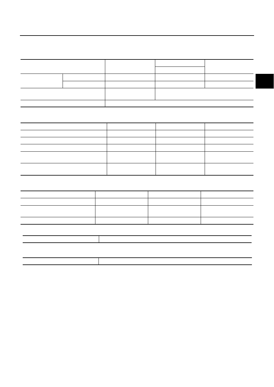
4.
Install clutch disc and clutch cover. Pre-tighten mounting bolts
and install a clutch aligner (SST).
5.
Tighten clutch cover attaching bolts evenly in two steps in the
order shown in the figure.
Tighten clutch cover attaching bolts according to the order shown in the figure. (K9K engine)
Flywheel surface runout
:
.
PCIB0016E
YCL034
Tool number
A: EM07020000 (CR,K9K engine)
A: KV30101000 (HR engine)
Tightening torque (CR engine)
First step
: 9.9 - 19 N·m (1.0 - 2.0 kg-m, 8 - 14 ft-lb)
Final step
: 22 - 29 N·m (2.2 - 3.0 kg-m, 17 - 21 ft-lb)
Tightening torque (HR engine)
First step
: 19 N·m (2.0 kg-m, 14 ft-lb)
Final step
: 22 - 29 N·m (2.2 - 3.0 kg-m, 17 - 21 ft-lb)
PCIB1503E

CL-14
CLUTCH DISC, CLUTCH COVER AND FLYWHEEL
6.
Install manual transaxle. Refer to
MT-7, "REMOVAL AND INSTALLATION"
(JH3) or
(JR5).
SERVICE DATA AND SPECIFICATIONS (SDS)
CL-15
D
E
F
G
H
I
J
K
L
M
A
B
CL
SERVICE DATA AND SPECIFICATIONS (SDS)
PFP:00030
Clutch Pedal
BCS000KV
Unit mm (in)
Clutch Disc
BCS000KW
Unit: mm (in)
Clutch Cover
BCS000KX
Unit: mm (in)
Clutch Control System
BCS000KY
Clutch Master Cylinder
BCS000KZ
Unit: mm (in)
Engine type
CR
K9K
HR
50/63kW
Pedal height
LHD models
160 - 169 (6.30 - 6.65)
170 - 180 (6.69 - 7.09)
160 - 169 (6.30 - 6.65)
RHD models
164 - 174 (6.46 - 6.85)
175 - 185 (6.89 - 7.23)
175 - 185 (6.89 - 7.23)
Pedal height at clutch disengagement
100 (3.94)
or more
—
Pedal free play
0.5 (0.02)
Engine type
CR14
K9K 50/63kW
HR
Size
190 (7.48) dia.
216 (8.50) dia.
200 (7.87) dia.
Wear limit (depth to rivet head)
0.3 (0.012)
—
0.3 (0.012)
Wearing thickness of facing
—
1 (0.039)
—
Runout limit/diameter of the area to be mea-
sured
1.0 (0.039)
or less / 180 (7.08) dia.
—
1.0 (0.039)
or less / 190 (7.48) dia.
Thickness of disc assy with load (new)
—
6.8 - 7.2
(0.27 - 0.28)
—
Engine type
CR
K9K 50/63kW
HR
Size
190 (7.48) dia.
216 (8.50) dia.
215 (8.46) dia.
Diaphragm spring lever height
32.0 - 34.0
(1. 26 - 1.34)
—
29.0 - 31.0
(1.14 - 1.22)
Uneven limit diaphragm spring toe height
0.7 (0.028) or less
0.8 (0.031) or less
0.7 (0.028) or less
Type of clutch control
Hydraulic
Inner diameter
15.87 (5/8)

CL-16
SERVICE DATA AND SPECIFICATIONS (SDS)
Document Outline
- QUICK REFERENCE INDEX
- CLUTCH
Wyszukiwarka
Podobne podstrony:
CL
CL
dire gelt pfte cl vni vla vc vox
dem Mejlechss ssude trinklied pfte cl vni vla vc vox
chosn kale mazl tov pfte cl vni vla vc vox
margaritkelekh pfte cl vni vla vc vox
Kramar Koncert pro 2 cl Op 35 parts 01 Clarinet in Bb
chemia, kwas chlorowodorowy, Kwas chlorowodorowy(solny)HCL H-CL s
bubliczki & intro pfte cl vni vla vc vox id 93714
bełz pfte cl vni vla vc vox
Kramar Koncert pro 2 cl Op 35
CL
a gruss mit mit di fejgl pfte cl vni vla vc vox
credit card visa hack ucam cl tr 560 [223 kb www netz ru] www!osiolek!com ACAXYQUJ6LJYAEVJKHBMLT2XNT
bei mir bistu shein pfte cl vni vla vc vox
oznaczanie cl
CL 024 Searching for Stowaways
ACURA CL 1997 2004
dos lidl fun goldenem land pfte cl vni vla vc vox
więcej podobnych podstron