

1/0

1/1
Contents
0
1
1 - Zelio Logic smart relays
Selection guide . . . . . . . . . . . . . . . . . . . . . . . . . . . . . . . . . . . . . . . . . . . . . page 1/2
Compact and modular smart relays
1 Presentation . . . . . . . . . . . . . . . . . . . . . . . . . . . . . . . . . . . . . . . . . . . . . . page 1/6
1 Functions . . . . . . . . . . . . . . . . . . . . . . . . . . . . . . . . . . . . . . . . . . . . . . . . page 1/10
1 Characteristics. . . . . . . . . . . . . . . . . . . . . . . . . . . . . . . . . . . . . . . . . . . . page 1/14
1 References . . . . . . . . . . . . . . . . . . . . . . . . . . . . . . . . . . . . . . . . . . . . . . page 1/22
Communication
1 Presentation . . . . . . . . . . . . . . . . . . . . . . . . . . . . . . . . . . . . . . . . . . . . . page 1/32
1 Programming protocol
2 Description. . . . . . . . . . . . . . . . . . . . . . . . . . . . . . . . . . . . . . . . . . . . . page 1/33
1 Modbus slave communication protocol
2 Description. . . . . . . . . . . . . . . . . . . . . . . . . . . . . . . . . . . . . . . . . . . . . page 1/34
2 References . . . . . . . . . . . . . . . . . . . . . . . . . . . . . . . . . . . . . . . . . . . . page 1/40
1 Ethernet server communication protocol
2 Description. . . . . . . . . . . . . . . . . . . . . . . . . . . . . . . . . . . . . . . . . . . . . page 1/37
2 References . . . . . . . . . . . . . . . . . . . . . . . . . . . . . . . . . . . . . . . . . . . . page 1/40
Analogue I/O extension modules
1 Presentation . . . . . . . . . . . . . . . . . . . . . . . . . . . . . . . . . . . . . . . . . . . . . page 1/42
1 References . . . . . . . . . . . . . . . . . . . . . . . . . . . . . . . . . . . . . . . . . . . . . . page 1/44
Modem communication interface
1 Presentation, description . . . . . . . . . . . . . . . . . . . . . . . . . . . . . . . . . . . . page 1/46
1 Functions . . . . . . . . . . . . . . . . . . . . . . . . . . . . . . . . . . . . . . . . . . . . . . . . page 1/48
1 Characteristics. . . . . . . . . . . . . . . . . . . . . . . . . . . . . . . . . . . . . . . . . . . . page 1/50
1 References . . . . . . . . . . . . . . . . . . . . . . . . . . . . . . . . . . . . . . . . . . . . . . page 1/52
1/2
1
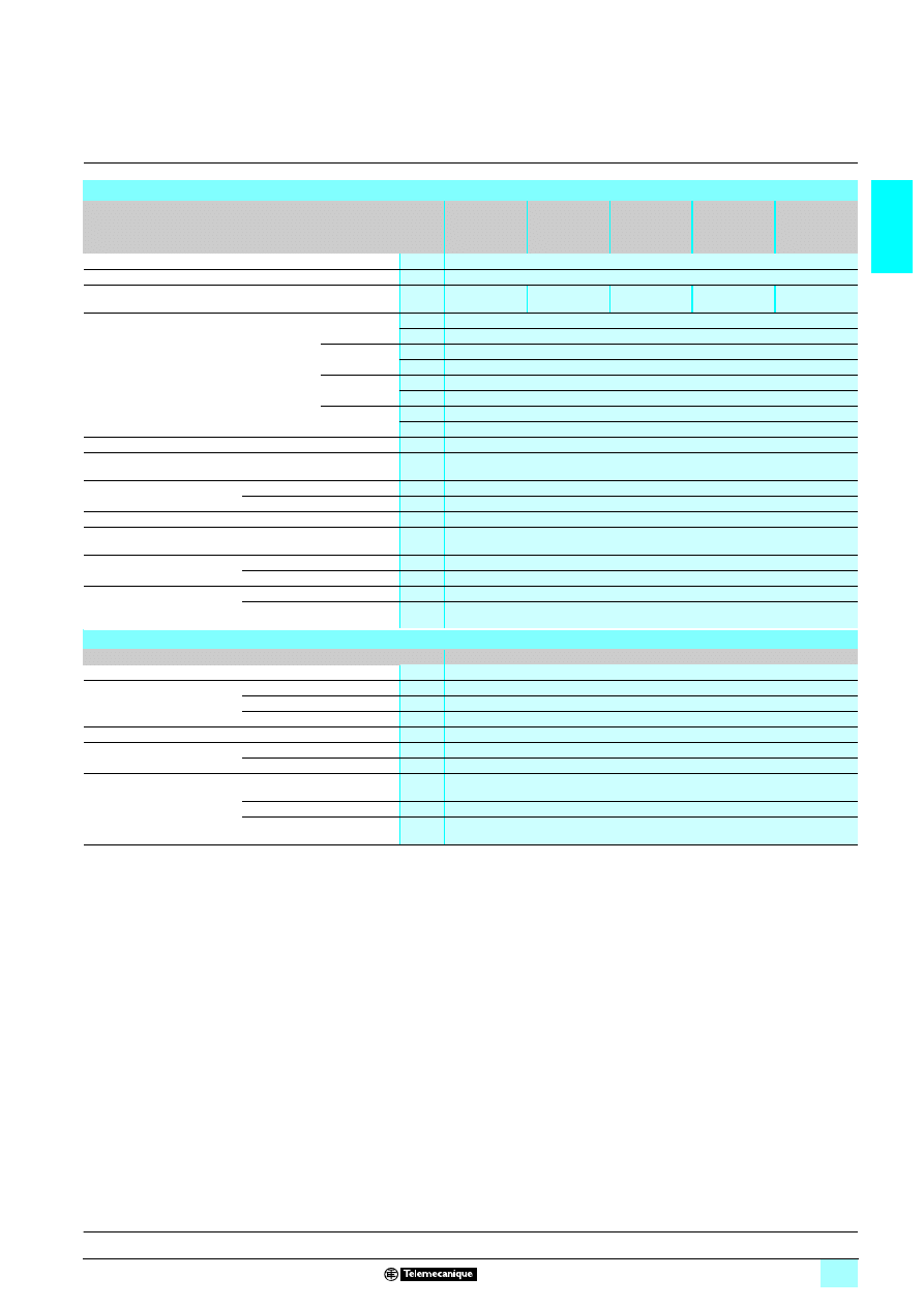
Selection guide
1
Zelio Logic smart relays
1
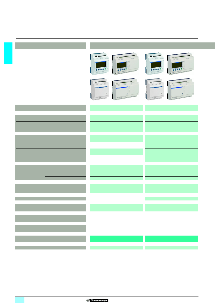
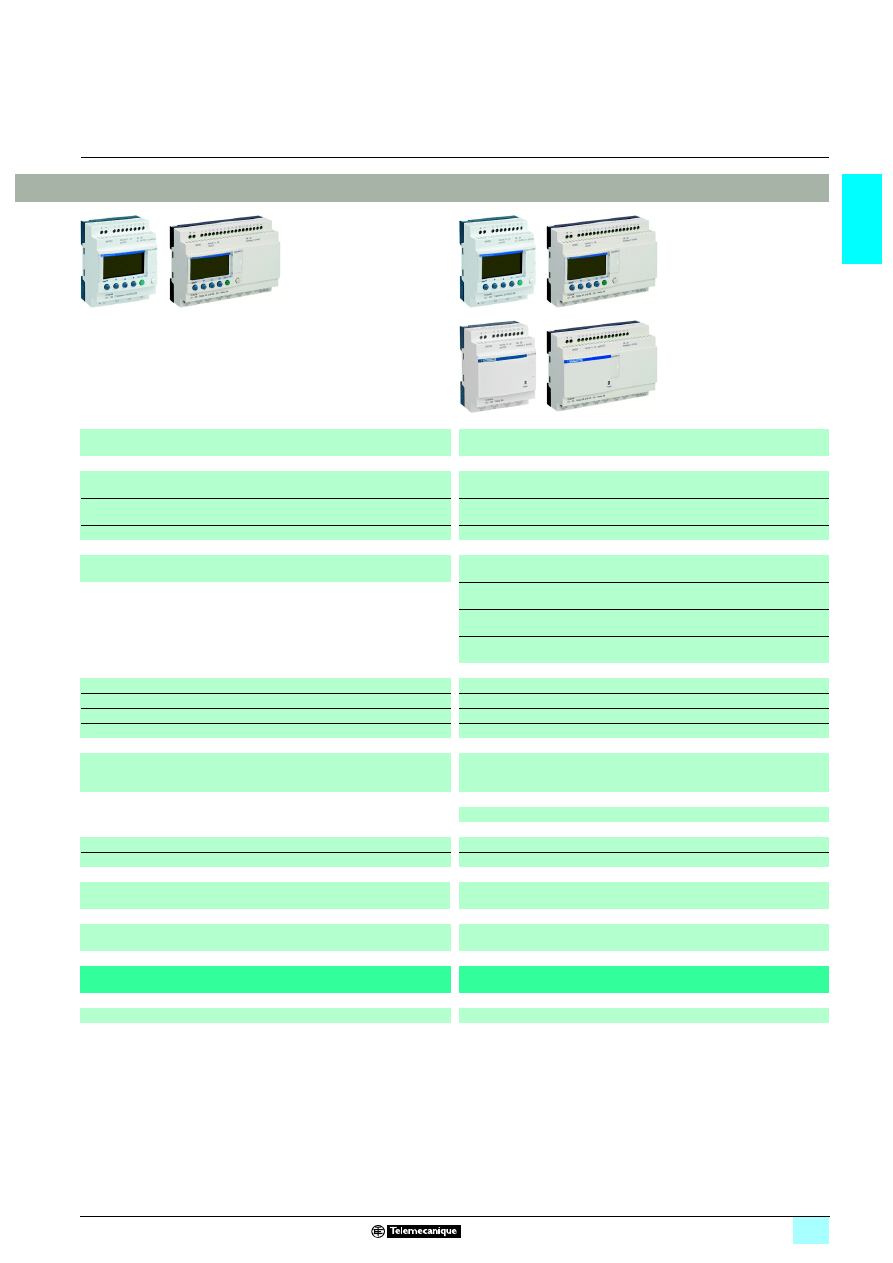
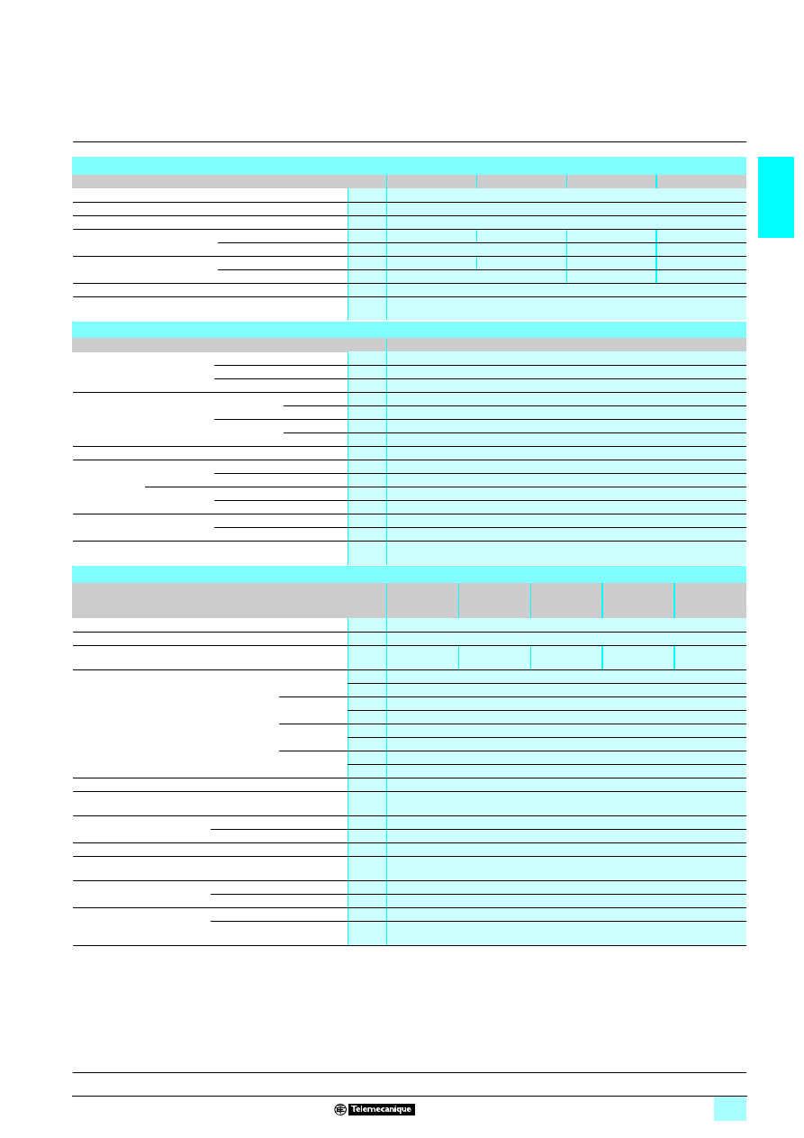
Compact smart relays
Product type
Compact smart relays
Supply voltage
1
1
1
1 24 V
1
1
1
1 100…240 V
Number of I/O
12
20
10
12
20
Number of discrete inputs
(of which analogue inputs)
8 (0)
12 (0)
6 (0)
8 (0)
12 (0)
Number of “relay”/“transistor” outputs
4/0
8/0
4/0
4/0
8/0
With display, with clock
Programming language
SR2 B
22
22
22
221B
FBD (1) or LADDER
SR2 B
22
22
22
221FU
FBD (1) or LADDER
With display, without clock
Programming language
SR2 A
22
22
22
221FU
LADDER only
Without display, with clock
Programming language
SR2 E
22
22
22
221B
FBD (1) or LADDER
SR2 E
22
22
22
221FU
FBD (1) or LADDER
Without display, without clock
Programming language
SR2 D
22
22
22
221FU
LADDER only
Programming software (see page 1/26)
“Zelio Soft 2” SR2 SFT01
“Zelio Soft 2” SR2 SFT01
Connection
accessories
(see page 1/26)
Serial link connecting cable
SR2 CBL01
SR2 CBL01
USB connecting cable
SR2 USB01
SR2 USB01
Bluetooth interface
SR2 BTC01
SR2 BTC01
Memory cartridge (see page 1/26)
SR2 MEM02
(
1
incompatible with SR2 COM01)
SR2 MEM02
(
1
incompatible with SR2 COM01)
“Discovery” packs (see page 1/22)
SR2 PACK
2222FU
Modem communication interface (see page 1/52)
SR2 COM01
SR2 COM01 (for SR2 B and SR2 E)
Alarm management software (see page 1/52)
“Zelio Logic Alarm” SR2 SFT02
“Zelio Logic Alarm” SR2 SFT02
Converters (thermocouple types J and K, Pt100 probes
and voltage/current) (see page 4/8) (2)
Power supplies for d.c. control circuit
(see page 7/17)
References
SR2
111
111
111
1111B
SR2
111
111
111
1111FU
Pages
1/22 and 1/23
1/22 and 1/23
(1) FBD: Function Block Diagram.
(2) See Analogue interfaces Zelio Analog, pages 4/2 to 4/9.
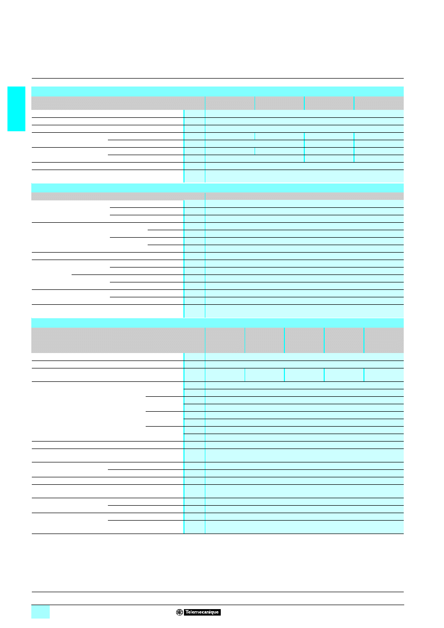
1/3
1
1
1
3
3
3
3 12 V
3
3
3
3 24 V
12
20
10
12
20
8 (4)
12 (6)
6 (0)
8 (4)
12 (2), 12 (6)
4/0
8/0
4/0
4/0, 0/4
8/0, 0/8
SR2 B
22
22
22
221JD
FBD (1) or LADDER
SR2 B
222
222
222
222BD
FBD (1) or LADDER
SR2 A
222
222
222
222BD
LADDER only
SR2 E
222
222
222
222BD
FBD (1) or LADDER
SR2 D
222
222
222
222BD
LADDER only
“Zelio Soft 2” SR2 SFT01
“Zelio Soft 2” SR2 SFT01
SR2 CBL01
SR2 CBL01
SR2 USB01
SR2 USB01
SR2 BTC01
SR2 BTC01
SR2 MEM02
(
1
incompatible with SR2 COM01)
SR2 MEM02
(
1
incompatible with SR2 COM01)
SR2 PACK
2222BD
SR2 COM01
SR2 COM01 (for SR2 B and SR2 E)
“Zelio Logic Alarm” SR2 SFT02
“Zelio Logic Alarm” SR2 SFT02
RM
2222 222
222
222
222BD
RM
2222 222
222
222
222BD
ABL 8MEM12020
ABL 8MEM240
22
22
22
22
ABL 7RM24025
SR2 B
11
11
11
111JD
SR2
1111
1111
1111
1111BD
1/22
1/22 and 1/23
1/4
1
Selection guide
1
Zelio Logic smart relays
1
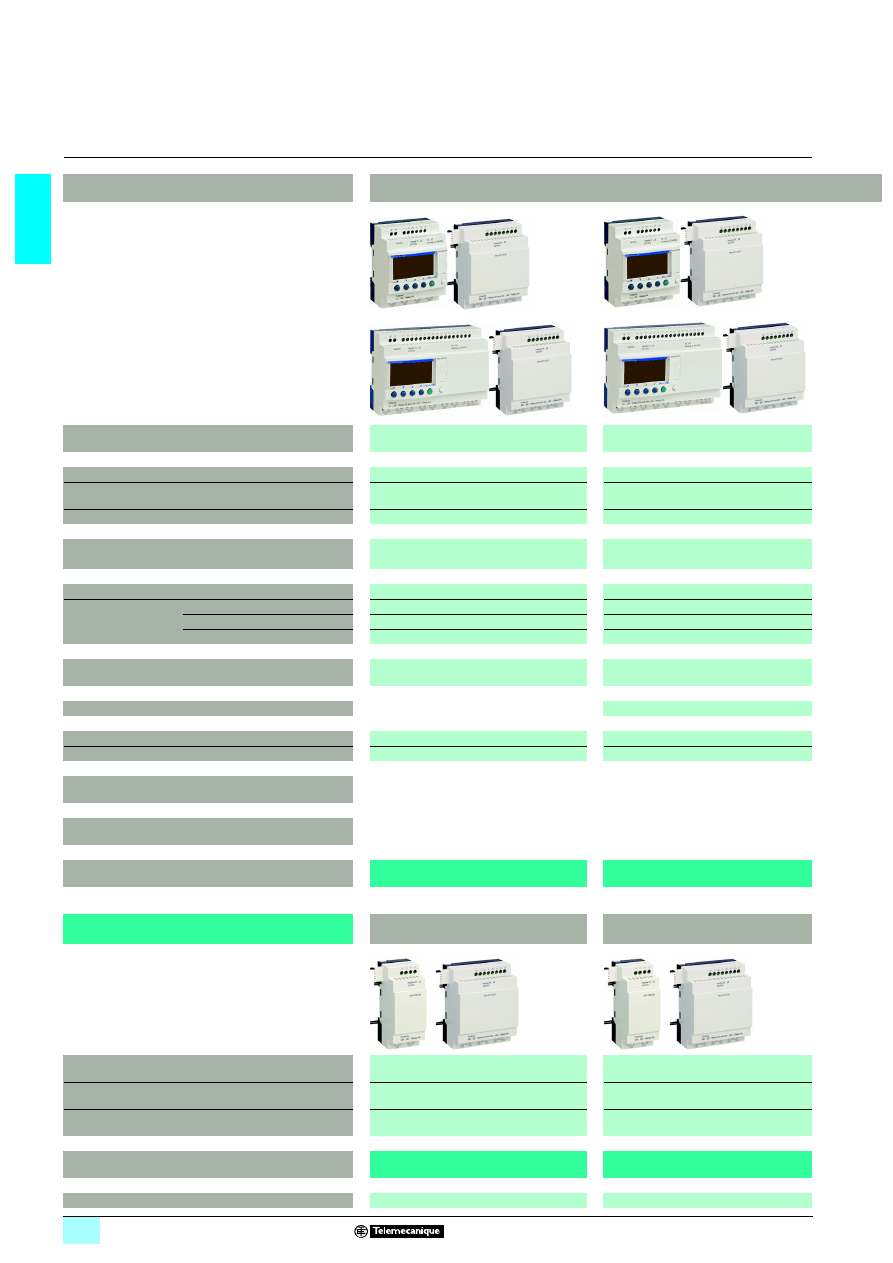
Modular smart relays and I/O extension and
communication modules
Product types
Modular smart relays
Supply voltage
1
1
1
1 24 V
1
1
1
1 100...240 V
Number of I/O
10
26
10
26
Number of discrete inputs
(of which analogue inputs)
6 (0)
16 (0)
6 (0)
16 (0)
Number of “relay”/“transistor” outputs
4/0
10/0
4/0
10/0
With display, with clock
Yes
Yes
Programming language
FBD or LADDER
FBD or LADDER
Programming software (see page 1/26)
“Zelio Soft 2” SR2 SFT01
“Zelio Soft 2” SR2 SFT01
Connection
accessories
(see page 1/26)
Serial link connecting cable
SR2 CBL01
SR2 CBL01
USB connecting cable
SR2 USB01
SR2 USB01
Bluetooth interface
SR2 BTC01
SR2 BTC01
Memory cartridge (see page 1/26)
SR2 MEM02
(
1
incompatible with SR2 COM01)
SR2 MEM02
(
1
incompatible with SR2 COM01)
“Discovery” packs (see page 1/24)
SR3 PACK
1BD
Modem communication interface (see page 1/52)
SR2 COM01
SR2 COM01
Alarm management software (see page 1/52)
“Zelio Logic Alarm” SR2 SFT02
“Zelio Logic Alarm” SR2 SFT02
Converters (thermocouple types J and K, Pt100 probes
and voltage/current) (see page 4/8) (1)
Power supplies for d.c. control circuit
(see page 7/17)
References (see page 1/24)
SR3 B
11
11
11
111B
SR3 B
22
22
22
221FU
(1) See Analogue interfaces Zelio Analog, pages 4/2 to 4/9.
Associated I/O extension and
communication module types
Discrete I/O extension modules
Discrete I/O extension modules
Number of I/O
6
10
14
6
10
14
Type and number of discrete inputs
(or analogue inputs)
4 (0)
6 (0)
8 (0)
4 (0)
6 (0)
8 (0)
Type and number of relay outputs
(or analogue outputs)
2 (0)
4 (0)
6 (0)
2 (0)
4 (0)
6 (0)
References
SR3 XT
111
111
111
111B
SR3 XT
111
111
111
111FU
Pages
1/25
1/25
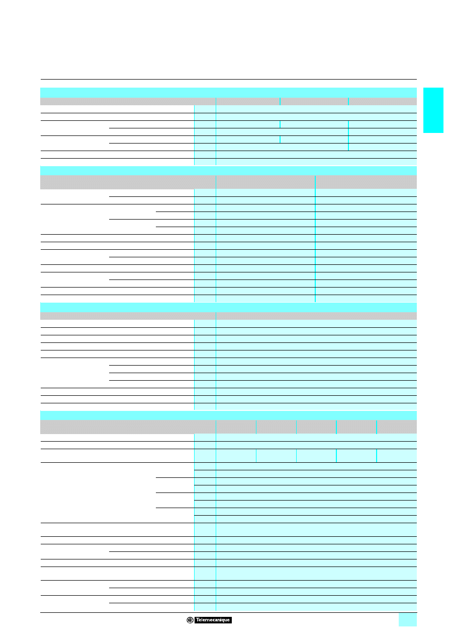
1/5
1
1
1
3
3
3
3 12 V
3
3
3
3 24 V
26
10
26
16 (6)
6 (4)
16 (6)
10/0
4/0, 0/4
10/0, 0/10
Yes
Yes
FBD or LADDER
FBD or LADDER
“Zelio Soft 2” SR2 SFT01
“Zelio Soft 2” SR2 SFT01
SR2 CBL01
SR2 CBL01
SR2 USB01
SR2 USB01
SR2 BTC01
SR2 BTC01
SR2 MEM02
(
12
incompatible with SR2 COM01)
SR2 MEM02
(
12
incompatible with SR2 COM01)
SR3 PACK
1BD
SR2 COM01
SR2 COM01
“Zelio Logic Alarm” SR2 SFT02
“Zelio Logic Alarm” SR2 SFT02
RM
24222
24222
24222
24222BD
RM
24222
24222
24222
24222BD
ABL 8MEM12020
ABL 8MEM24006, ABL 8MEM24012, ABL 7RM24025
SR3 B261JD
SR3 B
111
111
111
111BD
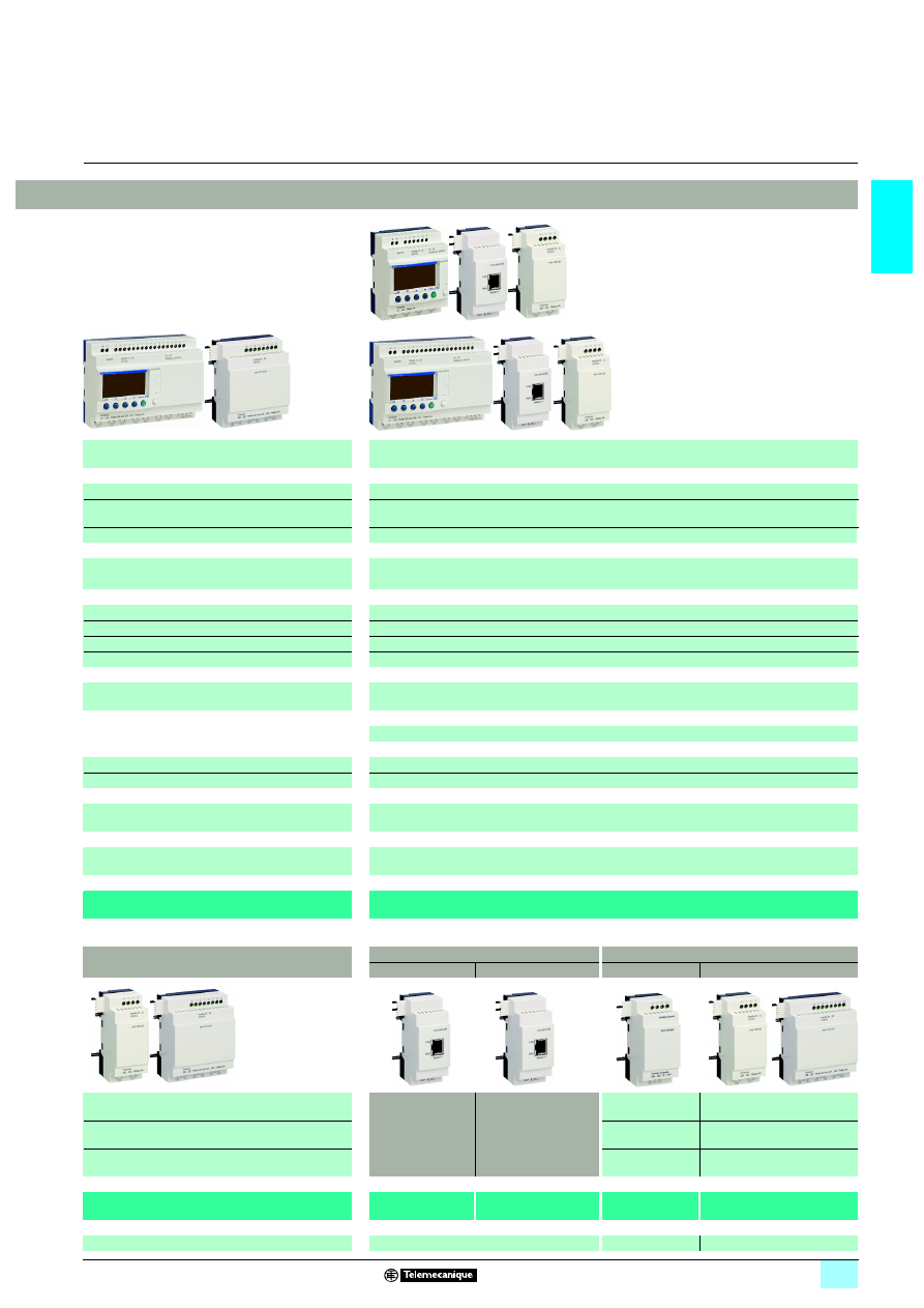
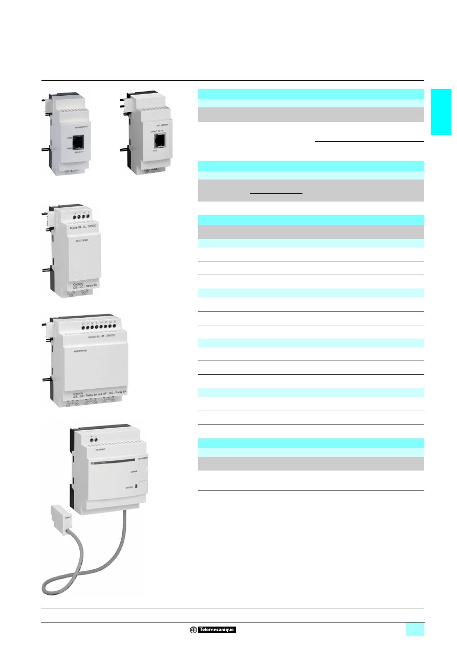
Discrete I/O extension modules
Network communication modules
I/O extension modules
Modbus slave
Ethernet server
Analogue
Discrete
6
10
14
2 Number of words:
3 4 (inputs)
3 4 (outputs)
3 4 (clock)
3 1 (status)
2 Number of words:
3 4 (inputs)
3 4 (outputs)
3 4 (clock)
3 1 (status)
4
6
10
14
4 (0)
6 (0)
8 (0)
0 (2)
4 (0)
6 (0)
8 (0)
2 (0)
4 (0)
6 (0)
0 (2)
2 (0)
4 (0)
6 (0)
SR3 XT
111
111
111
111JD
SR3 MBU01BD
SR3 NET01BD
SR3 XT43BD
SR3 XT
111
111
111
111BD
1/25
1/40
1/44
1/25
and
or
or
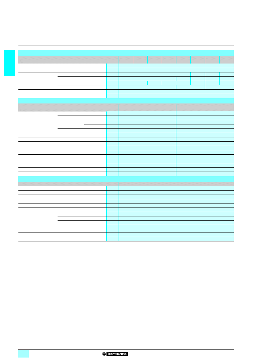
1/6
1
Presentation
1
Zelio Logic smart relays
1
Compact and modular smart relays
Presentation
Zelio Logic smart relays are designed for use in small automated systems. They are
used in both the industrial and commercial sectors.
2222 For industry:
23automation of small finishing, production, assembly or packaging machines.
23decentralised automation of ancillary equipment of large and medium-sized
machines (textile, plastics, materials processing sectors etc.),
23automation systems for agricultural machinery (irrigation, pumping, greenhouses
etc.).
2222 For the commercial/building sectors:
23automation of barriers, roller shutters, access control,
23automation of lighting systems,
23automation of compressors and air conditioning systems.
Their compact size and ease of setting-up make them a competitive alternative to
solutions based on cabled logic or specific cards.
2222 Programming
Simple programming, ensured by the universal nature of the languages, meets all the
requirements of automation specialists and also the needs of the electrician.
Programming can be performed:
23independently, using the buttons on the Zelio Logic smart relay (ladder language),
23on a PC using “Zelio Soft 2” software.
When using a PC, programming can be performed either in LADDER language or in
function block diagram (FBD) language, see pages 1/8 to 1/12.
Backlighting of the LCD display (1) is obtained by activating one of the 6 programming
buttons on the Zelio Logic smart relay or by programming with “Zelio Soft 2” software
(example: flashing in the event of a malfunction).
The autonomous operating time of the clock, assured by a lithium battery, is 10
years.
Data backup (preset values and current values) is provided by an EEPROM Flash
memory (10 years).
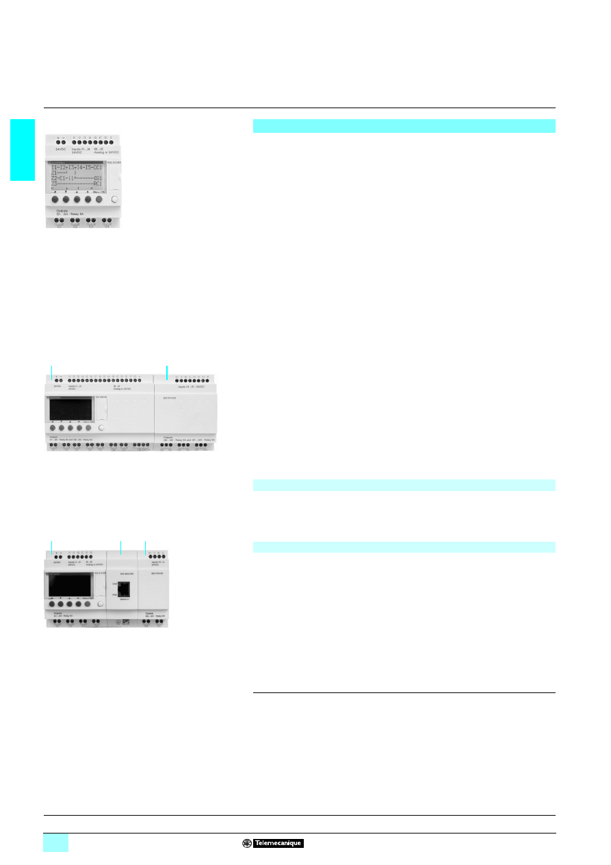
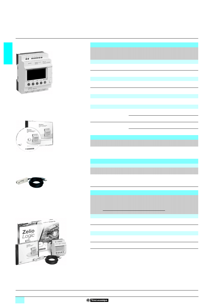
Compact smart relays
Compact smart relays meet requirements for simple automation systems.
The number of inputs/outputs can be:
1 12 or 20 I/O, supplied with 4 24 V or 5 12 V,
1 10, 12 or 20 I/O, supplied with 4 100…240 V or 5 24 V.
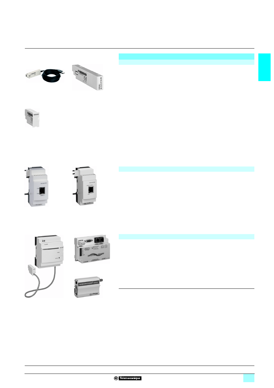
Modular smart relays and extensions
The number of inputs/outputs for modular smart relays can be:
1 26 I/O, supplied with 5 12 V,
1 10 or 26 I/O, supplied with 4 24 V, 4 100…240 V or 5 24 V
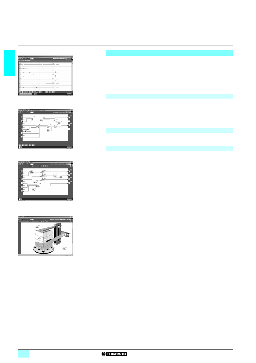
To improve performance and flexibility, Zelio Logic modular smart relays can be fitted
with communication modules and I/O extension modules to obtain a maximum of
40 I/O:
1 Modbus or Ethernet communication modules, supplied with 5 24 V via the
Zelio Logic smart relay at the same voltage.
1 analogue I/O extension modules with 4 I/O, supplied with 5 24 V via the
Zelio Logic smart relay at the same voltage,
1 discrete I/O extension modules with 6, 10 or 14 I/O, supplied via the Zelio Logic
smart relay at the same voltage.
(1) LCD: Liquid Crystal Display.
10
94
46
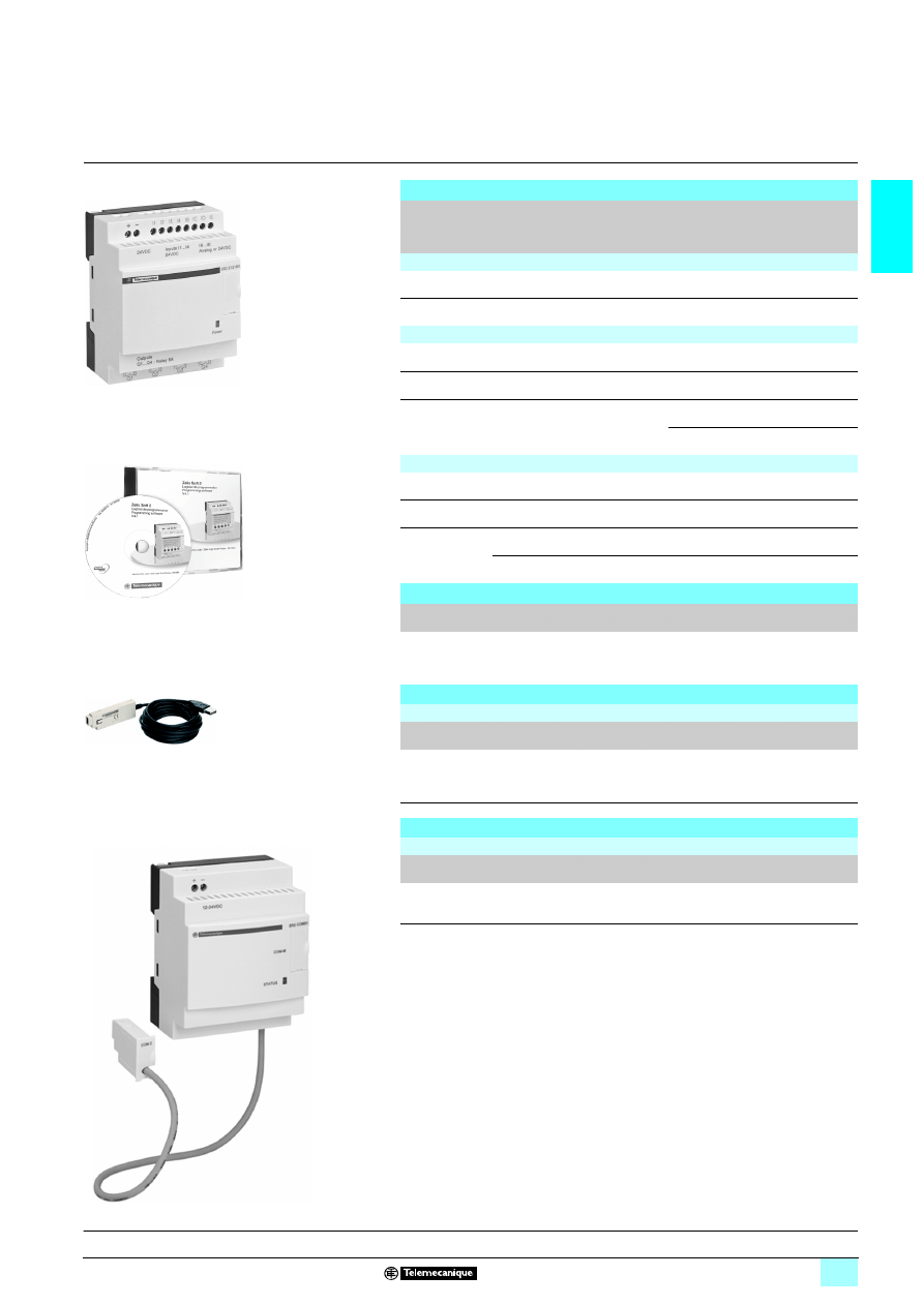
Zelio Logic compact smart relay
10
94
58
1
2
1
Zelio Logic modular smart relay
(10 or 26 I/O)
2
I/O extension module: discrete (6, 10 or 14
I/O) or analogue (4 I/O)
00
00
0
3
-2
6
1
2
1
Zelio Logic modular smart relay
(10 or 26 I/O)
2
Modbus or Ethernet communication
modules
3
I/O extension module: discrete (6, 10 or 14
I/O) or analogue (4 I/O)
3
Functions :
pages 1/10 to 1/12
Characteristics:
pages 1/14 to 1/19
Curves :
pages 1/20 and 1/21
References:
pages 1/22 to 1/27
Dimensions, schemes:
pages 1/28 to 1/31
Combination of modular smart relays with I/O
extension and communication modules
1
1
1
1
The order shown above must be observed when using
a Modbus slave or Ethernet server communication
module and a discrete or analogue I/O extension module.
An I/O extension module cannot be fitted before the
Modbus slave communication module.
1/7
1
Presentation
(continued)
1
Zelio Logic smart relays
1
Compact and modular smart relays
(1) Public Switched Telephone Network.
(2) Global System Mobile.
Communication
Cabled and wireless programming tools
1 These programming tools allow the Zelio Logic smart relay to be connected to a
PC running “Zelio Soft 2” software:
23Link by cables:
- Cable SR2 CBL01 to 9-pin serial port
or
- Cable SR2 USB01 to USB port
23Wireless link:
- Bluetooth interface SR2 BTC01
1 Memory cartridge
The Zelio Logic smart relay can be fitted with a backup memory cartridge which
enables the application program to be copied into another Zelio Logic smart relay.
However, loading and updating of the firmware (software embedded in the product)
is only possible with memory cartridge SR2 MEM02.
The memory cartridge also enables a backup copy of the program to be saved prior
to replacing the product.
When used with a smart relay without display or buttons, the copy of the program
contained in the cartridge is automatically transferred into the Zelio Logic smart relay
on power-up.
Modbus slave and Ethernet server communication modules
Modbus and Ethernet communication modules allow connection to automation
system equipment such as display units or programmable controllers
(see pages 1/32 to 1/41).
Modem communication interface
The “Modem communication interface” products in the Zelio Logic range include:
1 a Modem communication interface SR2 COM01 connected between a Zelio Logic
smart relay and a Modem,
1 analogue (PSTN) Modems (1) SR2 MOD01 or GSM Modem (2) SR2 MOD02,
1 “Zelio Logic Alarm” software SR2 SFT02.
They are designed for monitoring or remote control of machines or installations which
operate without personnel.
The Modem communication interface supplied with
5 12...24 V, enables messages,
telephone numbers and calling conditions to be stored, see pages 1/46 to 1/55.
52
34
09
Connecting cable
53
61
35
Bluetooth interface
53
49
44
Memory cartridge
54
04
54
Modbus
communication module
5
361
36
Ethernet
communication module
534
94
1
Modem
communication interface
53
49
43
Analogue
PSTN Modem
53
49
42
GSM Modem
Functions :
pages 1/10 to 1/12
Characteristics:
pages 1/14 to 1/19
Curves :
pages 1/20 and 1/21
References:
pages 1/22 to 1/27
Dimensions, schemes:
pages 1/28 to 1/31
1/8
1
Presentation
1
Zelio Logic smart relays
1
Compact and modular smart relays
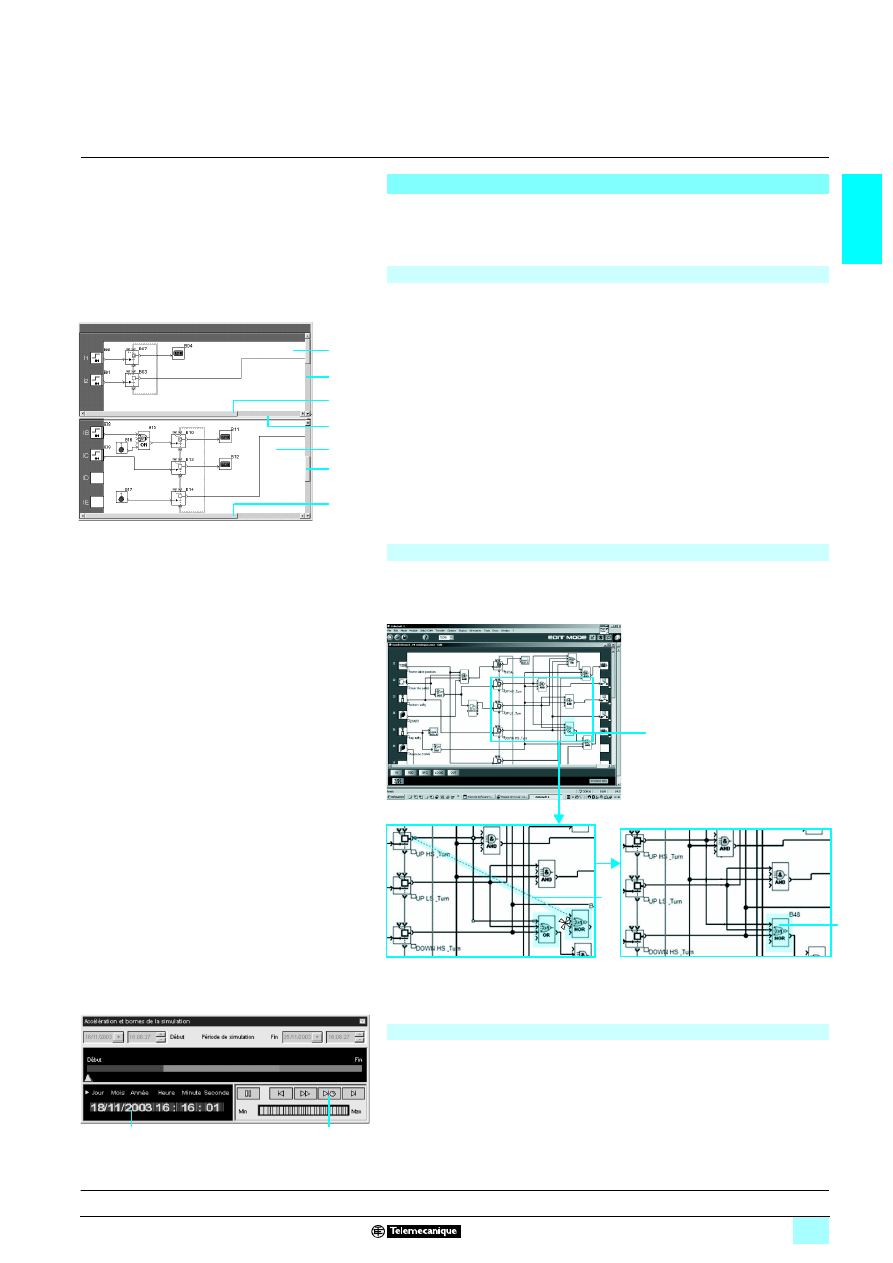
“Zelio Soft 2” programming software
“Zelio Soft 2” software enables:
1 programming in LADDER language or in function block diagram (FBD) language,
see pages 1/10 to 1/12,
1 simulation, monitoring and supervision,
1 uploading and downloading of programs,
1 output of personalised files,
1 automatic compiling of programs,
1 on-line help.
“Zelio Soft 2” software monitors applications by means of its coherence test function.
An indicator turns red at the slightest input error. The problem can be located by
simply clicking the mouse.
“Zelio Soft 2” software allows switching, at any time, to any of the 6 languages
(English, French, German, Spanish, Italian, Portuguese) and editing of the
application file in the selected language.
“Zelio Soft 2” software allows Text function blocks to be configured, which can then
be displayed on all Zelio Logic smart relays which have a display.
2 test modes are provided:
1 “Zelio Soft 2” simulation mode allows a program to be tested without a Zelio
Logic smart relay, i.e.:
23enable discrete inputs,
23display the status of outputs,
23vary the voltage of the analogue inputs,
23enable the programming buttons,
23simulate the application program in real time or in accelerated time,
23dynamically display (in red) the various active elements of the program.
1 “Zelio Soft 2” monitoring mode makes it possible to test the program executed by
the smart relay, i.e.:
23display the program “on-line”,
23force inputs, outputs, control relays and current values of the function blocks,
23adjust the time,
23change from STOP mode to RUN mode and vice versa.
In simulation or monitoring mode, the monitoring window allows the status of the
smart relay I/Os to be displayed within your application environment (diagram or
image).
“Zelio Soft 2” for PC (versions
2 4.1)
Programming in LADDER language
Coherence tests and application languages
Programming in FBD language
Inputting messages for display on Zelio Logic
Program testing
Simulation mode
Monitoring window
Functions :
pages 1/10 to 1/12
Characteristics:
pages 1/14 to 1/19
Curves :
pages 1/20 and 1/21
References:
pages 1/22 to 1/27
Dimensions, schemes:
pages 1/28 to 1/31
1/9
1
Presentation
(continued)
1
Zelio Logic smart relays
1
Compact and modular smart relays
“Zelio Soft 2” programming software
Version 4.1 of "Zelio Soft 2" software improves, amongst other things, the ease of
use of user interfaces for the following functions:
The wiring sheet can be split into 2. Splitting allows two separate parts of the wiring
sheet to be displayed on the same screen.
This makes it possible to:
1 Display the required function blocks in the top and bottom parts.
1 Move the split bar as required.
1 Connect the function blocks between the 2 parts of the wiring sheet.
The split wiring sheet is structured as follows:
1
View of top part
2
Top window vertical scroll bar
3
Top window horizontal scroll bar
4
Split bar
5
View of bottom part
6
Bottom window vertical scroll bar
7
Bottom window horizontal scroll bar
A function allows a block to be replaced without losing the input and output
connections.
E.g.: Replacement of an "OR" block by a "NOR" block.
Waiting
zzzz
LADDER or FBD program simulation mode allows the program to be debugged by
simulating it on the software workshop host computer.
A function allows the time on the simulator clock to be modified by setting to 3
seconds before the start of the next event.
The “Next event” button
1
allows modification of the simulator clock
2
.
User interfaces
"Split wiring sheet" function (FBD language)
1
2
3
4
5
6
7
Structure of a split wiring sheet
"Replacement of a function block" (FBD language)
1
"OR" block to be replaced
1
2
Move all links to the new "NOR" block
“
Acceleration and simulation terminals" window"
1
2
2
"Time Prog Simulation" function (LADDER and FBD languages)
3
Delete the "OR" block and position
the "NOR" block in its place
Functions :
pages 1/10 to 1/12
Characteristics:
pages 1/14 to 1/19
Curves :
pages 1/20 and 1/21
References:
pages 1/22 to 1/27
Dimensions, schemes:
pages 1/28 to 1/31
3

1/10
1
Functions
1
Zelio Logic smart relays
1
Compact and modular smart relays
“Zelio Soft 2” programming software
LADDER language
Definition
Text function block
Up/down counter
Analogue comparator
Control relay
LCD backlighting
Output coil
Timer
Fast counter
Clock
Counter comparator
Summer/Winter time switching
Message
LADDER language enables a LADDER program to be written with elementary
functions, elementary function blocks and derived function blocks, as well as with
contacts, coils and variables.
The contacts, coils and variables can be annotated. Text can be placed freely within
the graphic.
2222 Control scheme input modes
“Zelio input” mode enables users who have directly programmed the Zelio Logic
smart relay to find the same user interface, even when using the software for the first
time.
“Free input” mode, which is more intuitive, is very user-friendly and incorporates
many additional features.
With LADDER programming language, two alternative types of symbol can be used:
23LADDER symbols,
23electrical symbols.
“Free input” mode also allows the creation of mnemonics and notes associated with
each line of the program.
Instant switching from one input mode to the other is possible at any time, by simply
clicking the mouse.
Up to 120 control scheme lines can be programmed, with 5 contacts and 1 coil per
program line
2222 Functions:
2316 Text function blocks,
2316 time delay function blocks; parameters of 11 different types can be set for each
of these (1/10
th
second to 9999 hours),
2316 up/down counter function blocks from 0 to 32767,
231 fast counter (1 kHz),
2316 analogue comparator function blocks,
238 clock function blocks, each with 4 channels,
2328 control relays,
238 counter comparators,
23LCD screen with programmable backlighting,
23automatic Summer/Winter time switching,
23variety of functions: coil, latching (Set/Reset), impulse relay, contactor,
2328 message blocks (with communication interface, see page 1/46).
Functions
Function
Electrical scheme
LADDER language
Notes
Contact
I corresponds to the real state of the contact connected to the
input of the smart relay.
i corresponds to the inverse state of the contact connected to the
input of the smart relay.
Standard coil
The coil is energised when the contacts to which it is connected
are closed.
Latch coil (Set)
The coil is energised (set) when the contacts to which it is
connected are closed.
It remains set even if the contacts are no longer closed.
Unlatch coil
(Reset)
The coil is de-energised (reset) when the contacts to which it is
connected are closed.
It remains disabled even if the contacts are no longer closed.
13
14
22
21
or
or
I
i
A1
A2
A1
A2
S
A1
A2
R
Presentation:
pages 1/6 to 1/9
Characteristics:
pages 1/14 to 1/19
Curves :
pages 1/20 and 1/21
References:
pages 1/22 to 1/27
Dimensions, schemes:
pages 1/28 to 1/31
1/11
1
Functions
(continued)
1
Zelio Logic smart relays
1
Compact and modular smart relays
“Zelio Soft 2” programming software
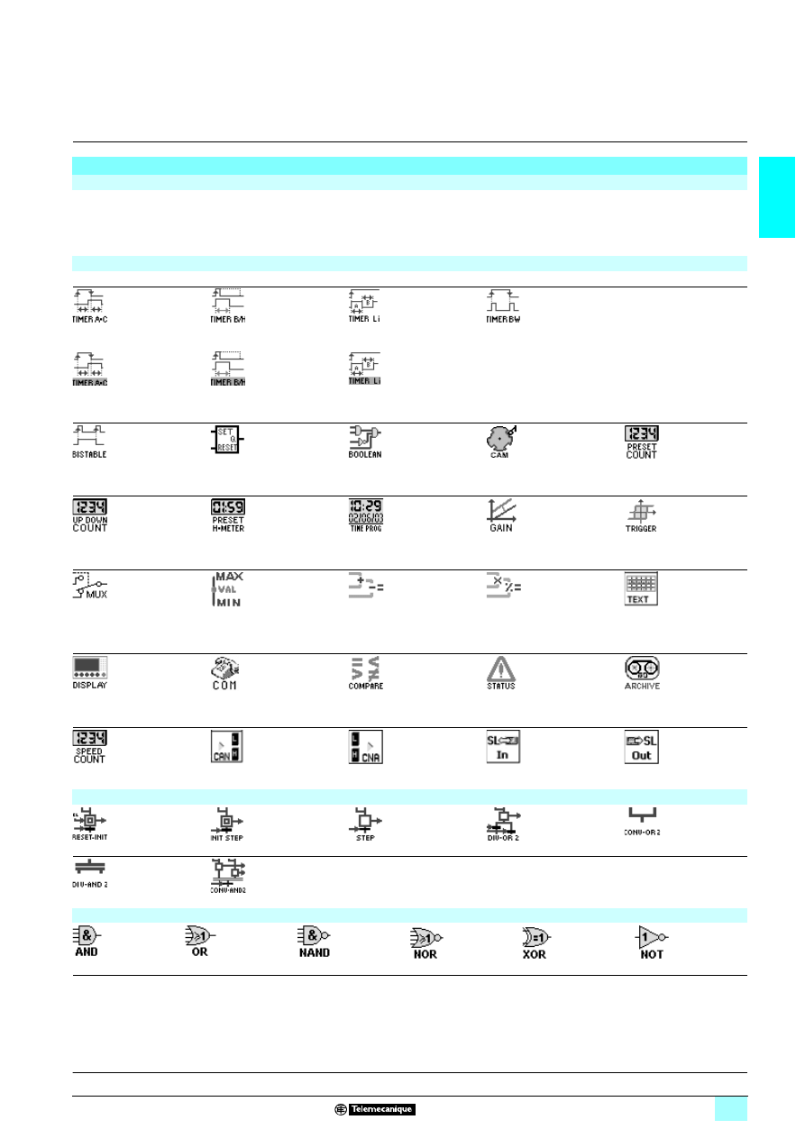
Function block diagram language (FBD / Grafcet SFC / Logic functions)
(1)
Definition
FBD language allows graphical programming based on the use of predefined function blocks; it provides the use of:
1 32 functions for counting, time delay, timing, definition of switching threshold, (for example: temperature regulation), generation of impulses,
time programming, multiplexing, display,
1 7 SFC functions,
1 6 logic functions.
Pre-programmed functions
Zelio Logic smart relays provide a high processing capacity, up to 200 function blocks, including 32 pre-programmed functions:
TIMER AC
TIMER BH
TIMER Li
TIMER BW
Timer. Function A/C
(ON-delay and OFF-delay)
Timer. Function BH.
(adjustable pulsed signal)
Pulse generator
(ON-delay, OFF-delay)
Timer. Function BW
(pulse on rising/falling edge)
Timer. Function A/C with
external preset adjustment
(ON-delay and OFF-delay)
Timer. Function BH with
external preset adjustment
(adjustable pulsed signal)
Pulse generator
with external preset adjustment
(ON-delay, OFF-delay)
BISTABLE
SET- RESET
BOOLEAN
CAM
PRESET COUNT
Impulse relay function
Bistable latching - Priority
assigned either to SET or
RESET function
Allows logic equations to be
created between connected
inputs
Cam programmer
Up/down counter
UP DOWN COUNT
PRESET H-METER
TIME PROG
GAIN
TRIGGER
Up/down counter with external
preset
Hour counter
(hour, minute preset)
Time programmer, weekly
and annual.
Allows conversion of an
analogue value by change of
scale and offset.
Defines an activation zone
with hysteresis
MUX
COMP IN ZONE
ADD/SUB
MUL/DIV
TEXT
Multiplexing functions on
2 analogue values
Zone comparison
(Min.
54
54
54
54Value 54
54
54
54Max.)
Add and/or subtract function
Multiply and/or divide function
Display of 4 pieces of data:
digital, analogue, date, time,
messages for Human-
Machine interface.
DISPLAY
COM
COMPARE
STATUS
ARCHIVE
Display of digital and analogue
data, date, time, messages for
Human-Machine interface.
Sending of messages with
communication interface
(see page 1/46)
Comparison of 2 analogue
values using the operands
=, >, <,
4, 5.
Access to smart relay status
Storage of 2 values
simultaneously
SPEED COUNT
CAN
CNA
SL In
SL Out
Fast counting up to
1 kHz
Analog/digital converter
Digital/analog converter
Input of a word via serial link
Output of a word via serial
link
SFC functions (2) (GRAFCET)
RESET-INIT
INIT STEP
STEP
DIV-OR 2
CONV-OR 2
Reinitialisable step
Initial step
SFC step
Divergence to OR
Convergence to OR
DIV-AND 2
CONV-AND 2
Divergence to AND
Convergence to AND
Logic functions
AND
OR
NAND
NOR
XOR
NOT
AND function
OR function
NOT AND function
NOT OR function
Exclusive OR function
NOT function
(1) Functional Block Diagram
(2) Sequential Function Chart.
Presentation:
pages 1/6 to 1/9
Characteristics:
pages 1/14 to 1/19
Curves :
pages 1/20 and 1/21
References:
pages 1/22 to 1/27
Dimensions, schemes:
pages 1/28 to 1/31
1/12
1
Functions
(continued)
1
Zelio Logic smart relays
1
Compact and modular smart relays
“Zelio Soft 2” programming software
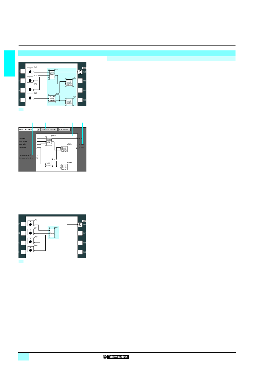
A Macro is a grouping of function blocks. It is characterised by its number, its name,
its links, its internal function blocks (255 max.) and by its I/O connections.
Seen from the outside, a Macro behaves like a function block with inputs and/or
outputs that can be connected to links.
Once created, a Macro can be manipulated like a function block.
1 Macro characteristics:
23The maximum number of Macros is 64.
23A password dedicated to Macros can be used to protect their content,
23A Macro can be edited / duplicated,
23A Macro's comments can be edited.
1 Macro properties:
A "Macro properties" dialogue box allows the properties of a Macro to be entered or
edited.
The properties of a Macro are:
23Macro name (optional)
23The block Symbol, which may be:
- an identifier,
- an image.
23Name of inputs.
23Name of outputs.
Function block diagram language (FBD / Grafcet SFC / Logic functions) (continued)
Macro Function
Creation of a Macro
Inside of a Macro
1
Macro selection
2
Edit properties
3
Allows return to external view of a Macro
4
Internal function block within the Macro
5
Non connected inputs
6
Non connected outputs
1
5
2
3
4
6
Outside of a Macro
1
Input connections
2
Output connection
2
1
Presentation:
pages 1/6 to 1/9
Characteristics:
pages 1/14 to 1/19
Curves :
pages 1/20 and 1/21
References:
pages 1/22 to 1/27
Dimensions, schemes:
pages 1/28 to 1/31
1/13
1
Description
1
Zelio Logic smart relays
1
Compact and modular smart relays
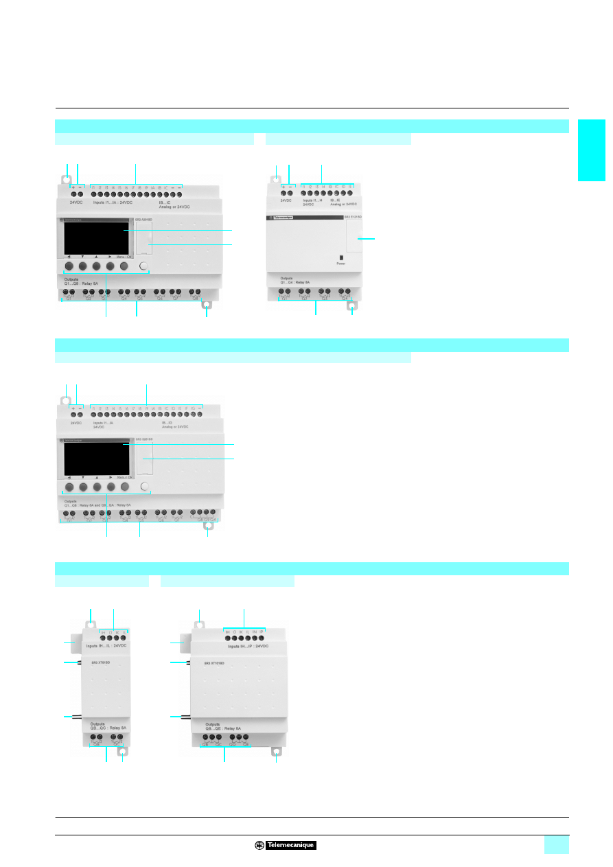
Compact smart relays
With display - 10, 12 and 20 I/O
Without display - 10, 12 and 20 I/O
Zelio Logic compact smart relays have the
following on their front panel:
1
Two retractable fixing lugs.
2
Two power supply terminals.
3
Terminals for connection of the inputs.
4
Backlit LCD display with 4 lines of 18
characters.
5
Slot for memory cartridge or connection
to a PC or Modem communication
interface.
6
6 buttons for programming and
parameter entry.
7
Terminals for connection of the outputs.
Modular smart relays
With display - 10 and 26 I/O
Zelio Logic modular smart relays have the
following on their front panel:
1
Two retractable fixing lugs.
2
Two power supply terminals.
3
Terminals for connection of the inputs.
4
Backlit LCD display with 4 lines of 18
characters.
5
Slot for memory cartridge or connection
to a PC or Modem communication
interface.
6
6 buttons for programming and
parameter entry.
7
Terminals for connection of the outputs.
Discrete I/O extension modules
6 discrete I/O
10 and 14 discrete I/O
Discrete I/O extension modules have the
following on their front panel:
1
Two retractable fixing lugs.
2
Terminals for connection of the inputs.
3
Terminals for connection of the outputs.
4
A connector for connection to the Zelio
Logic smart relay (powered via the Zelio
Logic smart relay).
5
Locating pegs.
1 2
3
5
1
7
4
6
1
2
3
5
1
7
1 2
3
5
1
7
4
6
1
2
5
1
3
5
4
1
2
5
1
3
5
5
4
Presentation, functions:
pages 1/6 to 1/12
Characteristics:
pages 1/14 to 1/19
Curves :
pages 1/20 and 1/21
References:
pages 1/22 to 1/27
Dimensions, schemes:
pages 1/28 to 1/31
1/14
1
Characteristics
1
Zelio Logic smart relays
1
Compact and modular smart relays
(1) Except for configuration SR3 B
111BD + SR3 MBU01BD + SR3 XT43BD or
SR3 B
111BD + SR3 NET01BD + SR3 XT43BD class A (class B: work in progress).
General environment characteristics
Type
SR2 A / SR2 B / SR2 D / SR2 E / SR3 B / SR3 XT
Product certifications
UL, CSA, GL, C-Tick
Conformity with the
low voltage directive
Conforming to 73/23/EEC
EN (IEC) 61131-2 (open equipment)
Conformity with the
EMC directive
Conforming to 89/336/EEC
EN (IEC) 61131-2 (Zone B)
EN (IEC) 61000-6-2, EN (IEC) 61000-6-3 (1) and EN (IEC) 61000-6-4
Degree of protection
Conforming to IEC/EN 60529
IP 20 (terminal block), IP 40 (front panel)
Overvoltage category
Conforming to IEC/EN 60664-1
3
Degree of pollution
Conforming to IEC/EN 61131-2
2
Ambient air temperature
around the device
conforming to IEC 60028-2-1
and IEC 60068-2-2
Operation
°C
- 20...+ 55 (+ 40 in non-ventilated enclosure)
Storage
°C
- 40...+ 70
Maximum relative humidity
Conforming to IEC/EN 60068-2-30
95% without condensation or dripping water
Maximum operating altitude
Operation
m
2000
Transport
m
3048
Mechanical resistance
Immunity to vibration
IEC/EN 60068-2-6, test Fc
Immunity to mechanical shock
IEC/EN 60068-2-27, test Ea
Resistance to
electrostatic discharge
Immunity to
electrostatic discharge
IEC/EN 61000-4-2, level 3
Resistance to HF interference
(immunity)
Immunity to electromagnetic
radiated fields
IEC/EN 61000-4-3
Immunity to fast transients
in bursts
IEC/EN 61000-4-4, level 3
Immunity to shock waves
IEC/EN 61000-4-5
Radio frequency
in common mode
IEC/EN 61000-4-6, level 3
Voltage dips and breaks (
6)
IEC/EN 61000-4-11
Immunity to damped
oscillation waves
IEC/EN 61000-4-12
Conducted and
radiated emissions
Conforming to EN 55022/11
(Group 1)
Class B (1)
Screw terminals connection
capacity
Flexible cable with cable end
mm
2
1 conductor: 0.25...2.5, cable: AWG 24...AWG 14
2 conductors: 0.25...0.75, cable: AWG 24...AWG 18
Semi-solid cable
mm
2
1 conductor: 0.25...2.5, cable: AWG 25...AWG 14
Solid cable
mm
2
1 conductor: 0.25...2.5, cable: AWG 25...AWG 14
2 conductors: 0.2...1.5, cable: AWG 24...AWG 16
Tightening torque
N.m
0.5 (tightened using Ø 3.5 mm screwdriver)
Processing characteristics
Number of control
scheme lines
With LADDER programming
120
Number of function blocks
With FBD programming
Up to 200
Cycle time
ms
6...90
Response time
ms
Input acquisition time + 1 to 2 cycle times
Back-up time
(in the event of power failure)
Day/time
10 years (lithium battery) at 25 °C
Program and adjustments in
the Zelio Logic smart relay and
in EEPROM memory cartridge
SR2 MEM0
1
10 years
Program memory checking
On each power-up
Clock drift
12 min/year (0 to 55 °C)
6 sec/month (at 25 °C and calibration)
Timer block accuracy
1% ± 2 of the cycle time
Presentation:
pages 1/6 to 1/9
Functions :
pages 1/10 to 1/12
Curves :
pages 1/20 and 1/21
References:
pages 1/22 to 1/27
Dimensions, schemes:
pages 1/28 to 1/31
1/15
1
Characteristics
(continued)
1
Zelio Logic smart relays
1
Compact and modular smart relays
Supply characteristics,
3424 V products
Type
SR2
2222121B
SR2
2222201B
SR3 B101B
SR3 B261B
Nominal voltage
V
6724
Voltage limits
V
6 20.4…28.8
Nominal frequency
Hz
50-60
Nominal input current
Without extensions
mA
145
233
160
280
With extensions
mA
–
280
415
Power dissipated
Without extensions
VA
4
6
4
7.5
With extensions
VA
–
7.5
10
Micro-breaks
Permissible duration
ms
4 10 (repeated 20 times)
rms insulation voltage
V
671780
Discrete input characteristics,
3424 V products
Type
SR
2222 2222
2222
2222
2222B
Nominal value of inputs
Voltage
V
6724
Current
mA
4,4
Frequencies
Hz
47...53 and 57...63
Input switching limit values
At state 1
Voltage
V
5 6714
Current
mA
> 2
At state 0
Voltage
V
4 675
Current
mA
< 0.5
Input impedance at state 1
k
Ω
4.6
Response
time
LADDER
language
State 0 to 1 (50/60 Hz)
ms
50
State 1 to 0 (50/60 Hz)
ms
50
FBD
language
State 0 to 1 (50/60 Hz)
ms
50 min., 255 max. (in increments of 10)
State 1 to 0 (50/60 Hz)
ms
50 min., 255 max. (in increments of 10)
Isolation
Between supply and inputs
None
Between inputs
None
Protection
Against inversion of terminals
Yes (control instructions not executed)
Relay output characteristics,
3424 V products
Type
SR2
2222121B
SR3 B101B
SR3 XT101B
SR2
2222201B
SR3 B261B
SR3 XT61B
SR3 XT141B
Operating limit values
V
8 5...30, 6 24...250
Contact type
N/O
Thermal current
A
4 outputs: 8 A
8 outputs: 8 A
8 outputs: 8 A
2 outputs: 5 A
2 outputs: 8 A
4 outputs: 8 A
2 outputs: 5 A
Electrical durability for
500 000 operating cycles
Conforming to
IEC/EN 60947-5-1
Utilisation
category
DC-12
V
8724
A
1.5
DC-13
V
8724 (L/R = 10 ms)
A
0.6
AC-12
V
67230
A
1.5
AC-15
V
67230
A
0.9
Minimum switching capacity
At minimum voltage of
8712 V mA
10
Low power switching
reliability of contact
8712 V - 10 mA
Maximum operating rate
No-load
Hz
10
At Ie (operational current)
Hz
0.1
Mechanical life
In millions of operating cycles
10
Rated impulse withstand
voltage (Uimp)
Conforming to IEC/EN 60947-1
and IEC/EN 60664-1
kV
4
Response time
Set
ms
10
Reset
ms
5
Built-in protection
Against short-circuits
None
Against overvoltage
and overload
None
Presentation:
pages 1/6 to 1/9
Functions :
pages 1/10 to 1/12
Curves :
pages 1/20 and 1/21
References:
pages 1/22 to 1/27
Dimensions, schemes:
pages 1/28 to 1/31
1/16
1
Characteristics
(continued)
1
Zelio Logic smart relays
1
Compact and modular smart relays
Supply characteristics,
3 100...240 V products
Type
SR2
2222101FU
SR2
2222121FU
SR2
2222201FU
SR3 B101FU
SR3 B261FU
Nominal voltage
V
6 100…240
Voltage limits
V
6 85…264
Nominal frequency
Hz
50-60
Nominal input current
Without extensions
mA
80/30
100/50
80/30
100/50
With extensions
mA
–
80/40
80/60
Power dissipated
Without extensions
VA
7
11
7
12
With extensions
VA
–
12
17
Micro-breaks
Permissible duration
ms
10
rms insulation voltage
V
671780
Discrete input characteristics,
3 100...240 V products
Type
SR
2222 2222
2222
2222
2222FU
Nominal value of inputs
Voltage
V
6 100... 240
Current
mA
0.6
Frequencies
Hz
47...53 and 57...63
Input switching limit values
At state 1
Voltage
V
5 6779
Current
mA
> 0.17
At state 0
Voltage
V
4 6740
Current
mA
< 0.5
Input impedance at state 1
k
Ω
350
Response
time
LADDER
language
State 0 to 1 (50/60 Hz)
ms
50
State 1 to 0 (50/60 Hz)
ms
50
FBD
language
State 0 to 1 (50/60 Hz)
ms
50 min... 255 max. (in increments of 10)
State 1 to 0 (50/60 Hz)
ms
50 min...255 max. (in increments of 10)
Isolation
Between supply and inputs
None
Between inputs
None
Protection
Against inversion of terminals
Yes (control instructions not executed)
Relay output characteristics,
3 100...240 V products
Type
SR2
2222101FU
SR2
2222121FU
SR3 B101FU
SR3 XT101FU
SR2
2222201FU
SR3 B261FU
SR3 XT61FU
SR3 XT141FU
Operating limit values
V
8 5...30. 6 24...250
Contact type
N/O
Thermal current
A
4 outputs: 8 A
8 outputs: 8 A
8 outputs: 8 A
2 outputs: 5 A
2 outputs: 8 A
4 outputs: 8 A
2 outputs: 5 A
Electrical durability for
500 000 operating cycles
Conforming to
IEC/EN 60947-5-1
Utilisation
category
DC-12
V
8724
A
1.5
DC-13
V
8724 (L/R = 10 ms)
A
0.6
AC-12
V
67230
A
1.5
AC-15
V
67230
A
0.9
Minimum switching capacity
At minimum voltage of
8712 V mA
10
Low power switching
reliability of contact
8712 V - 10 mA
Maximum operating rate
No-load
Hz
10
At Ie (operational current)
Hz
0.1
Mechanical life
In millions of operating cycles
10
Rated impulse withstand
voltage (Uimp)
Conforming to IEC/EN 60947-1
and IEC/EN 60664-1
kV
4
Response time
Set
ms
10
Reset
ms
5
Built-in protection
Against short-circuits
None
Against overvoltage
and overload
None
Presentation:
pages 1/6 to 1/9
Functions :
pages 1/10 to 1/12
Curves :
pages 1/20 and 1/21
References:
pages 1/22 to 1/27
Dimensions, schemes:
pages 1/28 to 1/31
1/17
1
Characteristics
(continued)
1
Zelio Logic smart relays
1
Compact and modular smart relays
Supply characteristics,
5 12 V products
Type
SR2 B121JD
SR2 B201JD
SR3 B261JD
Nominal voltage
V
8712
Voltage limits
Including ripple
V
8 10.4…14.4
Nominal input current
Without extensions
mA
120
200
250
With extensions
mA
–
400
Power dissipated
Without extensions
W
1.5
2.5
3
With extensions
W
–
5
Micro-breaks
Permissible duration
ms
4 1 (repeated 20 times)
Protection
Against reversed polarity
Yes
Discrete input characteristics,
5 12 V products
Type
SR
2222 2222
2222
2222
2222JD
(inputs I1…IA, IH…IR)
SR
2222 2222
2222
2222
2222JD
(inputs IB…IG used as discrete inputs)
Nominal value of inputs
Voltage
V
8712
8712
Current
mA
4
4
Input switching
limit values
At state 1
Voltage
V
5 8 5.6
5 8 7
Current
mA
5 2
5 0.5
At state 0
Voltage
V
4 8 2.4
4 8 3
Current
mA
< 0.9
< 0.2
Input impedance at state 1
k
Ω
2.7
14
Conforming to IEC/EN 61131-2
Type 1
Type 1
Sensor compatibility
3-wire
Yes PNP
Yes PNP
2-wire
No
No
Input type
Resistive
Resistive
Isolation
Between supply and inputs
None
None
Between inputs
None
None
Maximum counting frequency
kHz
1
1
Protection
Against reversed polarity
Yes (control instructions not executed)
Yes (control instructions not executed)
Analogue input characteristics,
5 12 V products
Type
SR
2222 2222
2222
2222
2222JD
(inputs IB…IG used as analogue inputs)
Input range
V
8 0...10 or 8 0...12
Input impedance
k
Ω
14
Maximum non destructive voltage
V
8714.4
Value of LSB
39 mV
Input type
Common mode
Conversion
Resolution
8 bits at maximum voltage
Conversion time
Smart relay cycle time
Precision
± 5 % at 25 °C and ± 6.2 % at 55 °C
Repeat accuracy
± 2 % at 55 °C
Isolation
Between analogue channel and supply
None
Cabling distance
m
10 max., with screened cable (sensor not isolated)
Protection
Against reversed polarity
Yes
Relay output characteristics,
5 12 V products
Type
SR2 B121JD
SR3 XT101JD
SR2 B201JD
SR3 B261JD
SR3 XT61JD
SR3 XT141JD
Operating limit values
V
8 5...30, 6 24...250
Contact type
N/O
Thermal current
A
4 outputs: 8 A
8 outputs: 8 A
8 outputs: 8 A
2 outputs: 5 A
2 outputs: 8 A
4 outputs: 8 A
2 outputs: 5 A
Electrical durability for
500 000 operating cycles
Conforming to
IEC/EN 60947-5-1
Utilisation category DC-12
V
8724
A
1.5
DC-13
V
8724 (L/R = 10 ms)
A
0.6
AC-12
V
67230
A
1.5
AC-15
V
67230
A
0.9
Minimum switching
capacity
At minimum voltage of
8712 V
mA
10
Low power switching reliability of contact
8712 V - 10 mA
Maximum operating rate
No-load
Hz
10
At Ie (operational current)
Hz
0.1
Mechanical life
In millions of operating cycles
10
Rated impulse withstand
voltage (Uimp)
Conforming to IEC/EN 60947-1
and IEC/EN 60664-1
kV
4
Response time
Set
ms
10
Reset
ms
5
Built-in protection
Against short-circuits
None
Against overvoltage and overload
None
1/18
1
Characteristics
(continued)
1
Zelio Logic smart relays
1
Compact and modular smart relays
Supply characteristics,
5 24 V products
Type
SR2
2222122221BD
SR2
B122BD
SR2
2222201BD
SR2
B202BD
SR3
B101BD
SR3
B102BD
SR3
B261BD
SR3
B262BD
Nominal voltage
V
8724
Voltage limits
Including ripple
V
19.2…30
Nominal input current
Without extensions
mA
100
50
190
70
With extensions
mA
–
100
160
300
180
Power dissipated
Without extensions
W
3
6
3
4
6
5
With extensions
W
–
8
10
Micro-breaks
Permissible duration
ms
4 1 (repeated 20 times)
Protection
Against reversed polarity
Yes
Discrete input characteristics,
5 24 V products
Type
SR
2222 2222
2222
2222
2222BD
(input
I1…IA, IH…IR)
SR
2222 2222
2222
2222
2222BD
(input
IB…IG used as discrete input)
Nominal value of inputs
Voltage
V
8724
8724
Current
mA
4
4
Input switching
limit values
At state 1
Voltage
V
5 8 15
5 8 15
Current
mA
5 2.2
5 1.2
At state 0
Voltage
V
4 8 5
4 8 5
Current
mA
< 0.75
< 0.5
Input impedance at state 1
k
Ω
7.4
12
Conforming to IEC/EN 61131-2
Type 1
Type 1
Sensor compatibility
3-wire
Yes PNP
Yes PNP
2-wire
No
No
Input type
Resistive
Resistive
Isolation
Between supply and inputs
None
None
Between inputs
None
None
Maximum counting frequency
kHz
1
1
Protection
Against reversed polarity
Yes (control instructions not executed)
Yes (control instructions not executed)
Analogue input characteristics,
5 24 V products
Type
SR
2222 2222
2222
2222
2222BD (input
IB…IG used as analogue inputs)
Input range
V
8 0...10 or 8 0...24
Input impedance
k
Ω
12
Maximum non destructive voltage
V
8730
Value of LSB
39 mV
Input type
Common mode
Conversion
Resolution
8 bits at maximum voltage
Conversion time
Smart relay cycle time
Precision
± 5 % at 25 °C and ± 6.2 % at 55 °C
Repeat accuracy
± 2 % at 55 °C
Isolation
Between analogue channel and
supply
None
Cabling distance
m
10 maximum, with screened cable (sensor not isolated)
Protection
Against reversed polarity
Yes
Presentation:
pages 1/6 to 1/9
Functions :
pages 1/10 to 1/12
Curves :
pages 1/20 and 1/21
References:
pages 1/22 to 1/27
Dimensions, schemes:
pages 1/28 to 1/31
1/19
1
Characteristics
(continued)
1
Zelio Logic smart relays
1
Compact and modular smart relays
(1) If there is no volt-free contact between the Zelio Logic smart relay output and the load.
Relay output characteristics,
5 24 V products
Type
SR2
2222101BD
SR2
2222121BD
SR3 B101BD
SR3 XT101BD
SR2
2222201BD
SR3 B261BD
SR3 XT61BD
SR3 XT141BD
Operating limit values
V
8 5...30. 6 24...250
Contact type
N/O
Thermal current
A
4 outputs: 8 A
8 outputs: 8 A
8 outputs: 8 A
2 outputs: 5 A
2 outputs: 8 A
4 outputs: 8 A
2 outputs: 5 A
Electrical durability for
500 000 operating cycles
Conforming to
IEC/EN 60947-5-1
Utilisation
category
DC-12
V
8724
A
1.5
DC-13
V
8724 (L/R = 10 ms)
A
0.6
AC-12
V
67230
A
1.5
AC-15
V
67230
A
0.9
Minimum switching capacity
At minimum voltage of
8 12 V
mA
10
Low power switching
reliability of contact
8712 V - 10 mA
Maximum operating rate
No-load
Hz
10
At Ie (operational current)
Hz
0.1
Mechanical life
In millions of operating cycles
10
Rated impulse withstand
voltage (Uimp)
Conforming to IEC/EN 60947-1
and IEC/EN 60664-1
kV
4
Response time
Set
ms
10
Reset
ms
5
Built-in protection
Against short-circuits
None
Against overvoltage
and overload
None
Transistor output characteristics,
5 24 V products
Type
SR
2222 B22
22
22
222BD
Operating limit values
V
8 19.2..0.30
Load
Nominal voltage
V
8724
Nominal current
A
0.5
Maximum current
A
0.625 at 30 V
Residual voltage
At state 1
V
4 8 2 for I = 0.5 A
Response time
Set
ms
4 1
Reset
ms
4 1
Built-in protection
Against overload and
short-circuits
Yes
Against overvoltage (1)
Yes
Against inversions of
power supply
Yes
Presentation:
pages 1/6 to 1/9
Functions :
pages 1/10 to 1/12
Curves :
pages 1/20 and 1/21
References:
pages 1/22 to 1/27
Dimensions, schemes:
pages 1/28 to 1/31
1/20
1
Curves
1
Zelio Logic smart relays
1
Compact and modular smart relays
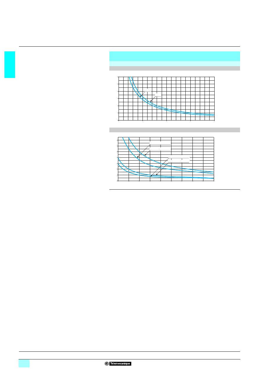
Electrical durability of relay outputs
(in millions of operating cycles, conforming to IEC/EN 60947-5-1)
d.c. loads
DC-12 (1)
DC-13 (2)
(1) DC-12: switching resistive loads and photo-coupler isolated solid-state loads, L/R
4 1 ms.
(2) DC-13: switching electromagnets, L/R
4 2 x (Ue x Ie) in ms, Ue: rated operational voltage,
Ie: rated operational current (with a protection diode on the load, DC-12 curves must be used
with a coefficient of 0.9 applied to the number in millions of operating cycles).
0
1,5
1
2
0,5
0,0
0,5
1,0
1,5
2,0
2,5
3,0
24 V
48 V
M
ill
io
ns of o
per
a
ting cycles
Current (A)
0,1
0,3
0,5
0,7
0,9
1
0,2
0,4
0,6
0,8
0,0
1,4
1,2
1,0
0,8
0,6
0,4
0,2
L/R = 10 ms 24 V
L/R = 10 ms 48 V
L/R = 60 ms 48 V
L/R = 60 ms 24 V
M
illion
s
of op
er
at
in
g cycles
Current (A)
Presentation:
pages 1/6 to 1/9
Functions :
pages 1/10 to 1/12
Characteristics:
pages 1/14 to 1/19
References:
pages 1/22 to 1/27
Dimensions, schemes:
pages 1/28 to 1/31
1/21
1
Curves
(continued)
1
Zelio Logic smart relays
1
Compact and modular smart relays
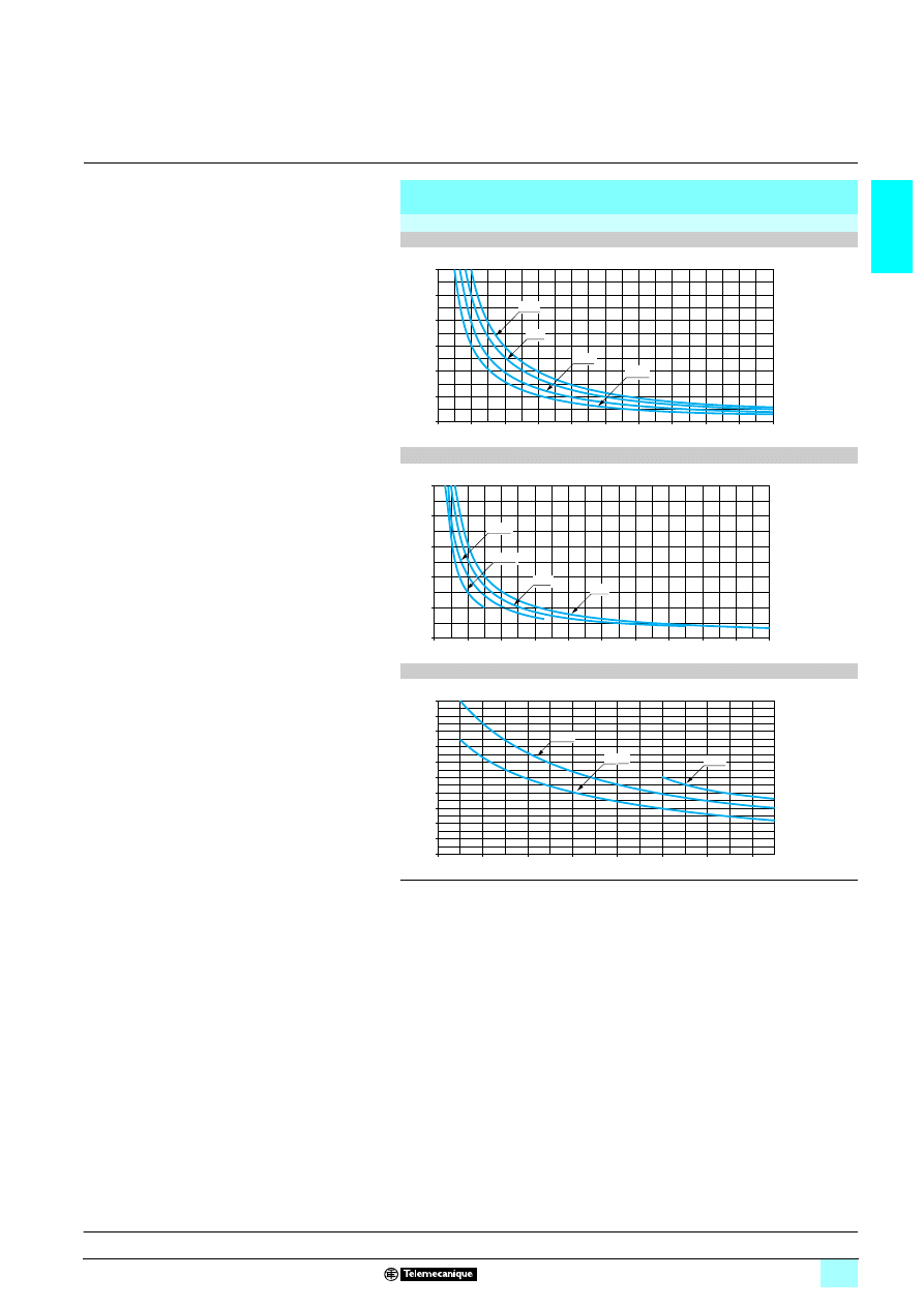
Electrical durability of relay outputs
(continued)
(in millions of operating cycles, conforming to IEC/EN 60947-5-1)
a.c. loads
AC-12 (1)
AC-14 (2)
AC-15 (3)
(1) AC-12: switching resistive loads and photo-coupler isolated solid-state loads, cos
5 0.9.
(2) AC-14: switching small electromagnetic loads
4 72 VA, make: cos = 0.3, break: cos = 0.3.
(3) AC-15: switching electromagnetic loads > 72 VA, make: cos = 0.7, break: cos = 0.4.
0
0,5
1,5
2,5
3,5
4,5
1,0
2,0
3,0
4,0
5
0,0
0,5
1,0
1,5
2,0
2,5
3,0
24 V
48 V
110 V
230 V
M
ill
io
ns of o
per
a
ting cycles
Current (A)
0
0,2
0,6
1,0
1,4
1,8
0,4
0,8
1,2
1,6
2
0,0
0,5
1,0
1,5
2,0
2,5
24 V
48 V
110 V
230 V
M
illion
s
of op
er
atin
g cycles
Current (A)
0,5
0,9
0,7
1,3
1,1
1,7
1,5
1,9
0,0
0,1
0,2
0,3
0,4
0,5
0,6
0,7
0,8
0,9
1,0
230 V
48 V
110 V
M
illions
of ope
ra
ting
cycles
Current (A)
Presentation:
pages 1/6 to 1/9
Functions :
pages 1/10 to 1/12
Characteristics:
pages 1/14 to 1/19
References:
pages 1/22 to 1/27
Dimensions, schemes:
pages 1/28 to 1/31

1/22
1
References
1
Zelio Logic smart relays
1
Compact smart relays
Compact smart relays with display
Number
of
I/O
Discrete
inputs
Including
8 0-10 V
analogue
inputs
Relay
outputs
Transistor
outputs
Clock
Reference
Weight
kg
Supply
3
3
3
3 24 V
12
8
0
4
0
Yes
SR2 B121B
0.250
20
12
0
8
0
Yes
SR2 B201B
0.380
Supply
3
3
3
3 100...240 V
10
6
0
4
0
No
SR2 A101FU (1)
0.250
12
8
0
4
0
Yes
SR2 B121FU
0.250
20
12
0
8
0
No
SR2 A201FU (1)
0.380
Yes
SR2 B201FU
0.380
Supply
4
4
4
4 12 V
12
8
4
4
0
Yes
SR2 B121JD
0.250
20
12
6
8
0
Yes
SR2 B201JD
0.380
Supply
4
4
4
4 24 V
10
6
0
4
0
No
SR2 A101BD (1)
0.250
12
8
4
4
0
Yes
SR2 B121BD
0.250
0
4
Yes
SR2 B122BD
0.220
20
12
2
8
0
No
SR2 A201BD (1)
0.380
6
8
0
Yes
SR2 B201BD
0.380
0
8
Yes
SR2 B202BD
0.280
“Zelio Soft 2” software for PC
Description
Application
Reference
Weight
kg
Programming software
“Zelio Soft 2”, multi-language
For PC, supplied on
CD-ROM (2), compatible with
Windows 98, NT, 2000, XP
SR2 SFT01
0.200
Accessories
Connection accessories
Description
Application
Length
Reference
Weight
kg
Connecting cable
Between the PC
(USB connector)
and the Zelio Logic
smart relay
3 m
SR2 USB01
0.100
Other accessories: see pages 1/26 and 1/27
Compact “discovery” packs
Number
of
I/O
Pack contents:
- Compact smart relay with display
- “Zelio Soft 2” programming software supplied on
CD-Rom
- Cable PC SR2 USB01 for connection to PC (3)
Reference
Weight
kg
Description of compact smart relay with display
Supply
3
3
3
3 100...240 V
12
SR2 B121FU
SR2 PACKFU
0.700
20
SR2 B201FU
SR2 PACK2FU
0.850
Supply
4
4
4
4 24 V
12
SR2 B121BD
SR2 PACKBD
0.700
20
SR2 B201BD
SR2 PACK2BD
0.700
Modem communication interface
Supply
4
4
4
4 12...24 V
Description
Application
Reference
Weight
kg
Modem communication
interface
For SR2 B
See page 1/52
0.200
(1) Programming on Zelio Logic smart relay in LADDER language only.
(2) CD-ROM comprising “Zelio Soft 2” software, an application library, a self-training manual,
installation instructions and a user’s manual.
(3) Replaces cable SR2 CBL01 which is still available separately, as an accessory
(see page 1/26).
10
94
40
SR2 A201BD
SR2 SFT01
53
63
07
SR2 PACK
111
53
63
08
Modem communication interface
5
363
06
Presentation:
pages 1/6 to 1/9
Functions :
pages 1/10 to 1/12
Characteristics:
pages 1/14 to 1/19
Curves :
pages 1/20 and 1/21
Dimensions, schemes:
pages 1/28 to 1/31
1/23
1
References
(continued)
1
Zelio Logic smart relays
1
Compact smart relays
Compact smart relays without display
Number
of
I/O
Discrete
inputs
Including
45
45
45
45
0-10 V
analogue
inputs
Relay
outputs
Transistor
outputs
Clock
Reference
Weight
kg
Supply
3
3
3
3 24 V
12
8
0
4
0
Yes
SR2 E121B
0.220
20
12
0
8
0
Yes
SR2 E201B
0.350
Supply
3
3
3
3 100...240 V
10
6
0
4
0
No
SR2 D101FU (1)
0.220
12
8
0
4
0
Yes
SR2 E121FU
0.220
20
12
0
8
0
No
SR2 D201FU (1)
0.350
Yes
SR2 E201FU
0.350
Supply
4
4
4
4 24 V
10
6
0
4
0
No
SR2 D101BD (1)
0.220
12
8
4
4
0
Yes
SR2 E121BD
0.220
20
12
2
8
0
No
SR2 D201BD (1)
0.350
6
8
0
Yes
SR2 E201BD
0.350
“Zelio Soft 2” software for PC
Description
Application
Reference
Weight
kg
Programming software
“Zelio Soft 2” software,
multi-language
For PC, supplied on
CD-Rom (2), compatible with
Windows 98, NT, 2000, XP
SR2 SFT01
0.200
Accessories
Connection accessories
Description
Application
Length
Reference
Weight
kg
Connecting cable
Between the PC
(USB connector)
and the Zelio Logic
smart relay
3 m
SR2 USB01
0.100
Other accessories: see pages 1/26 and 1/27
Modem communication interface
Supply
4
4
4
4 12...24 V
Description
Application
Reference
Weight
kg
Modem communication
interface
For SR2 E
See page 1/52
0.200
(1) Programming on Zelio Logic smart relay in LADDER language only.
(2) CD-ROM comprising “Zelio Soft 2” software, an application library, a self-training manual,
installation instructions and a user’s manual.
10
94
42
SR2 E121BD
SR2 SFT01
53
63
07
SR2 USB01
52
31
09
53
63
06
Modem communication interface
Presentation:
pages 1/6 to 1/9
Functions :
pages 1/10 to 1/12
Characteristics:
pages 1/14 to 1/19
Curves :
pages 1/20 and 1/21
Dimensions, schemes:
pages 1/28 to 1/31
1/24
1
References
1
Zelio Logic smart relays
1
Modular smart relays
Modular smart relays with display
Number
of
I/O
Discrete
inputs
Including
45
45
45
45
0-10 V
analogue
inputs
Relay
outputs
Transistor
outputs
Clock
Reference
Weight
kg
Supply
3
3
3
3 24 V
10
6
0
4
0
Yes
SR3 B101B
0.250
26
16
0
10 (1)
0
Yes
SR3 B261B
0.400
Supply
3
3
3
3 100...240 V
10
6
0
4
0
Yes
SR3 B101FU
0.250
26
16
0
10 (1)
0
Yes
SR3 B261FU
0.400
Supply
4
4
4
4 12 V
26
16
6
10 (1)
0
Yes
SR3 B261JD (2)
0.400
Supply
4
4
4
4 24 V
10
6
4
4
0
Yes
SR3 B101BD
0.250
0
4
Yes
SR3 B102BD
0.220
26
16
6
10 (1)
0
Yes
SR3 B261BD
0.400
0
10
Yes
SR3 B262BD
0.300
“Zelio Soft 2” software for PC
Description
Application
Reference
Weight
kg
Programming software
“Zelio Soft 2” software,
multi-language
For PC, supplied on
CD-ROM (3), compatible with
Windows 98, NT, 2000, XP
SR2 SFT01
0.200
Accessories
Connection accessories
Description
Application
Length
Reference
Weight
kg
Connecting cable
Between the PC
(USB connector)
and the Zelio Logic
smart relay
3 m
SR2 USB01
0.100
Other accessories: see pages 1/26 and 1/27
Modular “discovery” packs
Number
of
I/O
Pack contents:
- Compact smart relay with display
- “Zelio Soft 2” programming software supplied on
CD-Rom
- Cable PC SR2 USB01 for connection to PC (4)
Reference
Weight
Description of compact smart relay with display
kg
Supply
3
3
3
3 100...240 V
10
SR3 B101FU
SR3 PACKFU
0.700
26
SR3 B261FU
SR3 PACK2FU
0.850
Supply
4
4
4
4 24 V
10
SR3 B101BD
SR3 PACKBD
0.700
26
SR3 B261BD
SR3 PACK2BD
0.850
(1) Including 8 outputs at maximum current of 8 A and 2 outputs at maximum current of 5 A.
(2) Can only be used with "Zelio Soft 2" software version
5V 3.1.
(3) CD-ROM comprising “Zelio Soft 2” software, an application library, a self-training manual,
installation instructions and a user’s manual.
(4) Replaces cable SR2 CBL01 which is still available separately, as an accessory
(see page 1/26).
Note: The Zelio Logic smart relay and its associated extensions must have an identical voltage.
10
94
44
SR3 B101BD
SR2 SFT01
53
63
07
SR2 USB01
52
310
9
SR2 PACK
111
53
63
08
Presentation:
pages 1/6 to 1/9
Functions :
pages 1/10 to 1/12
Characteristics:
pages 1/14 to 1/19
Curves :
pages 1/20 and 1/21
Dimensions, schemes:
pages 1/28 to 1/31
1/25
1
References
(continued)
1
Zelio Logic smart relays
1
Modular smart relays
Modbus and Ethernet communication module
(1)
4
4
4
4 24 V supply (via smart relays SR3B...BD)
For use with
Network
Reference
Weight
kg
Zelio Logic modular smart relays
SR3 B
22
22
22
221BD and SR3 B22
22
22
222BD
Modbus
See page 1/40
0.110
Ethernet
See page 1/40
0.110
53
63
14
Ethernet
communication module
52
41
32
Modbus
communication module
Analogue I/O extension module
(2)
Supply
4
4
4
4 24 V (via Zelio Logic smart relay SR3 B...BD)
Number
of
I/O
Inputs
Including
4
4
4
4
Inclu-
ding
Pt100
Output
4
4
4
4
0-10 V
Reference
Weight
kg
0 - 10 V
0 - 20 mA
4
2 (3)
2 max
2 max
1 max
2
See page 1/44
0.110
Discrete I/O extension modules
Number
of I/O
Discrete inputs
Relay outputs
Reference
Weight
kg
Supply
3
3
3
3 24 V (via Zelio Logic smart relays SR3 B111
111
111
111B)
6
4
2
SR3 XT61B
0.125
10
6
4
SR3 XT101B
0.200
14
8
6 (4)
SR3 XT141B
0.220
Supply
3
3
3
3 100-240 V (via Zelio Logic smart relays SR3 B111
111
111
111FU)
6
4
2
SR3 XT61FU
0.125
10
6
4
SR3 XT101FU
0.200
14
8
6 (4)
SR3 XT141FU
0.220
Supply
4
4
4
4 12 V (via Zelio Logic smart relay SR3 B261JD)
6
4
2
SR3 XT61JD
0.125
10
6
4
SR3 XT101JD
0.200
14
8
6 (4)
SR3 XT141JD
0.220
Supply
4
4
4
4 24 V (via Zelio Logic smart relays SR3 B111
111
111
111BD)
6
4
2
SR3 XT61BD
0.125
10
6
4
SR3 XT101BD
0.200
14
8
6 (4)
SR3 XT141BD
0.220
Modem communication interface
(5)
Supply
4
4
4
4 12...24 V
Description
Reference
Weight
kg
Modem communication interface
See page 1/52
0.200
(1) See pages 1/32 to 1/41.
(2) See pages 1/42 to 1/45.
(3) See page 1/45.
(4) Including 4 outputs at maximum current of 8 A and 2 outputs at maximum current of 5 A.
(5) See pages 1/46 to 1/55.
Note: The Zelio Logic smart relay and its associated extensions must have an identical voltage.
10
93
63
SR3 XT61BD
1
0
9
3
6
9
SR3 XT141BD
Modem communication interface
53
63
06
Presentation:
pages 1/6 to 1/9
Functions :
pages 1/10 to 1/12
Characteristics:
pages 1/14 to 1/19
Curves :
pages 1/20 and 1/21
Dimensions, schemes:
pages 1/28 to 1/31
1/26
1
References
1
Zelio Logic smart relays
1
Compact and modular smart relays
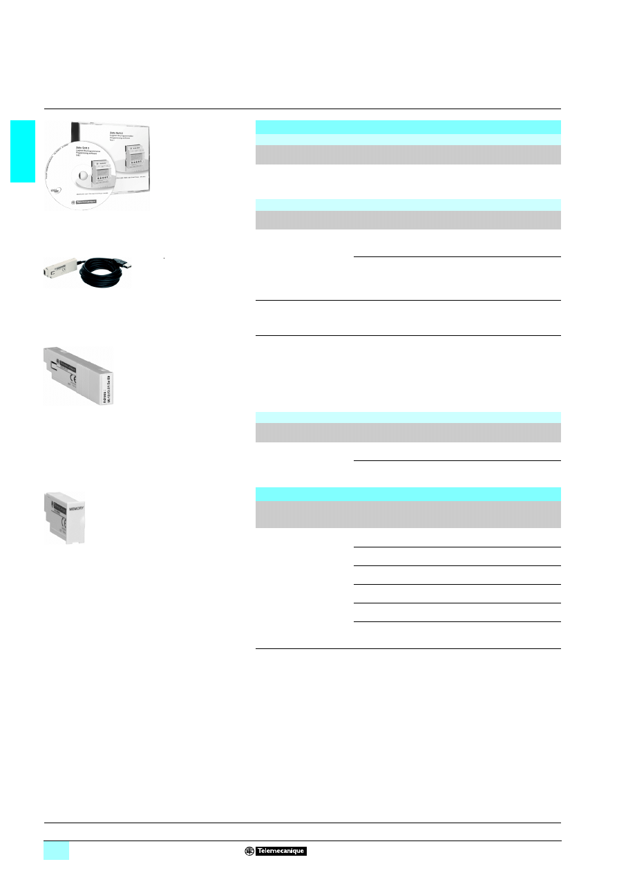
Programming
“Zelio Soft 2” software for PC
Description
Application
Reference
Weight
kg
Programming software
“Zelio Soft 2” software,
multi-language
For PC, supplied on
CD-ROM (1), compatible with
Windows 98, NT, 2000, XP
SR2 SFT01
0.200
Connection accessories
Description
Application
Reference
Weight
kg
Connecting cables
Between the PC (SUB-D, 9-pin
connector) and the Zelio Logic
smart relay. Length: 3 m
SR2 CBL01
0.150
Between the PC (USB connector)
and the Zelio Logic smart relay.
PC compatible with
Windows 2000, XP
Length: 3 m
SR2 USB01
0.100
Bluetooth interface
for Zelio Logic smart relays
Between the PC (wireless link)
and the Zelio Logic smart relay.
Range 10 m (class 2)
SR2 BTC01 (2)
0.015
Bluetooth adapter
for non-equipped PC
To be used in conjunction with
SR2 BTC01 when the PC is not
equipped with Bluetooth
technology.
Connection to the USB port
on the PC.
PC compatible with
Windows 98SE, 2000, XP
Range of 10 m (class 2)
VW3 A8115
0.290
Memory cartridges
(3)
Description
Application
Reference
Weight
kg
EEPROM
memory cartridges
For firmware (software embedded
in the smart relay) version
4 2.4
SR2 MEM01
0.010
For firmware (software embedded
in the smart relay) version
5 3.0
SR2 MEM02
0.010
Documentation
Description/application
Language
Reference
Weight
kg
User’s manual
for direct programming on
the Zelio Logic smart relay
English
SR2 MAN01EN
0.100
French
SR2 MAN01FR
0.100
German
SR2 MAN01DE
0.100
Spanish
SR2 MAN01ES
0.100
Italian
SR2 MAN01IT
0.100
Portuguese
SR2 MAN01P0
0.100
(1) CD-ROM comprising “Zelio Soft 2” software, an application library, a self-training manual,
installation instructions and a user’s manual.
(2) Can only be used with "Zelio Soft 2" software version
2 V 4.1.
(3) Program loading using memory cartridge SR2 MEM02 is incompatible with Modem
communication interface SR2 COM01.
SR2 SFT01
53
63
07
SR2 USB01
52
31
09
SR2 BTC01
53
61
35
SR2 MEM02
53
49
44
Presentation:
pages 1/6 to 1/9
Functions :
pages 1/10 to 1/12
Characteristics:
pages 1/14 to 1/19
Curves :
pages 1/20 and 1/21
Dimensions, schemes:
pages 1/28 to 1/31
1/27
1
References
(continued)
1
Zelio Logic smart relays
1
Compact and modular smart relays
Regulated switch mode power supplies
(1)
Input
voltage
Nominal
output voltage
Reference
Weight
kg
6 100...240 V (50/60 Hz)
8 5 V, 8 12 V or 8 24 V
See page 7/17
–
Converters
(2)
Description
Reference
Weight
kg
Converters for J and K type thermocouples,
for Pt100 probes and voltage/current
See page 4/8
–
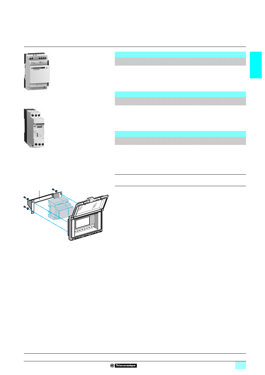
Mounting accessories
(3)
Description/application
Mounting capacity
Reference
Weight
kg
Dust and damp-proof
enclosure
with split blanking plate
arrangement, fitted with an
IP 55 dust and damp-proof
window with hinged flap, for
mounting through a door
- 1 or 2 SR2 smart relays with
10 or 12 I/O or
- 1 SR2 smart relay with 20 I/O or
- 1 SR3 smart relay with 10 I/O
+ 1 I/O extension module
(6, 10 or 14 I/O) or
- 1 SR3 smart relay with 26 I/O
+ 1 I/O extension module (6 I/O).
14210
0.350
Fixing bracket and
symmetrical mounting rail
For mounting enclosure 14210
through a door panel
14211
0.210
(1) See pages 7/12 to 7/17.
(2) See pages 4/4 to 4/9.
(3) Products marketed under the Merlin Gerin brand.
Regulated switch mode
power supplie
54
04
72
Converters for
thermocouples
10
90
00
14210
14211
D
F
56
399
0
Presentation:
pages 1/6 to 1/9
Functions :
pages 1/10 to 1/12
Characteristics:
pages 1/14 to 1/19
Curves :
pages 1/20 and 1/21
Dimensions, schemes:
pages 1/28 to 1/31
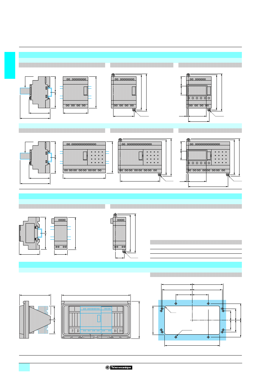
1/28
1
Dimensions,
mounting
1
Zelio Logic smart relays
1
Compact and modular smart relays
Compact and modular smart relays
SR
1111 111110111
111
111
111 (10 I/O), SR2 111112111
111
111
111 (12 I/O)
Mounting on 35 mm
6
6
6
6 rail
Screw fixing (retractable lugs)
Position of display
SR2
111120111
111
111
111 (20 I/O), SR3 B26111
111
111
111 (26 I/O)
Mounting on 35 mm
6
6
6
6 rail
Screw fixing (retractable lugs)
Position of display
(1) With SR2 USB01 or SR2 BTC01
I/O extension modules
SR3 XT61
11
11
11
11 (6 I/O), SR3 XT10111
11
11
11 and SR3 XT141115
115
115
115(10 and 14 I/O)
Mounting on 35 mm
6
6
6
6 rail
Screw fixing (retractable lugs)
SR3
a
G
XT61
11
35.5
25
XT101
11
72
60
XT141
11
72
60
Enclosure + fixing bracket
14210 + 14211
Cut-out
71,2
90
=
=
107,6
59,5
59,9
2xØ4
100
107,6
59,9
2xØ4
100
24
29
48
5,5
84
(1)
124,6
90
113,3
100
=
=
59,5
84
2xØ4
107,6
100
2xØ4
107,6
113,3
24
29
48
5,5
(1)
a
=
=
59,5
G
100
107,6
90
2xØ4
186
96
32
32
40,5
57
57
40,5
55
12xØ5
r=2
101,5
101,5
104,5
104,5
55
234
105
126
=
=
Presentation:
pages 1/6 to 1/9
Functions :
pages 1/10 to 1/12
Characteristics:
pages 1/14 to 1/19
Curves :
pages 1/20 and 1/21
References:
pages 1/22 to 1/27
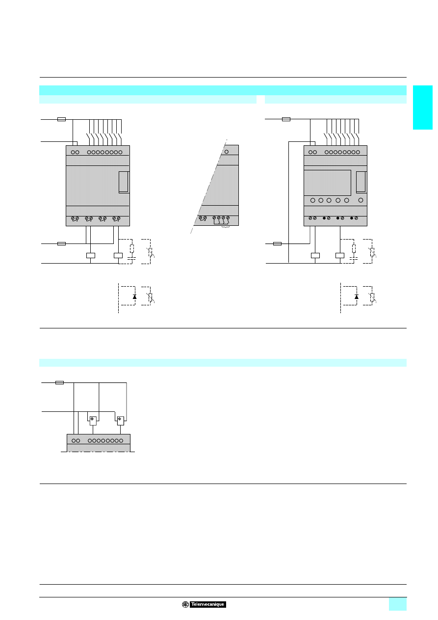
1/29
1
Schemes
1
Zelio Logic smart relays
1
Compact and modular smart relays
Connection of smart relays on
5 supply
SR
15111
15111
15111
151111BD, SR15111
15111
15111
151111JD
SR2 B
11
11
11
112BD and SR3 B11
11
11
112BD
SR3 B261
1D
(1) 1 A quick-blow fuse or circuit-breaker.
(2) Fuse or circuit-breaker.
(3) Inductive load.
(4) Q9 and QA: 5 A (max. current in terminal C: 10 A).
Discrete input used for 3-wire sensors
(1) 1 A quick-blow fuse or circuit-breaker.
+
SRp ppppJD
c 12 V
SRp ppppBD
c 24 V
–
(1)
+
–
Q1
Q2
Q3
Q4
z 12…240 V
50/60 Hz
c 12…24 V
L /
+
N /
–
z 24…240 V
50/60 Hz
c 12…24 V
(2)
(3)
U
(3)
U
or
–
6
Q7
C Q8 Q9 QA
IA IB IC ID IE IF IG
5 A
(4)
+
–
+
c 24 V
c 24 V
–
+
–
(1)
+
Q1
Q2
Q3
Q4
(2)
+
–
z 12…240 V
50/60 Hz
c 12…24 V
(3)
U
(3)
U
BN
BK
BL
BN
BK
BL
+
–
(1)
+
–
Presentation:
pages 1/6 to 1/9
Functions :
pages 1/10 to 1/12
Characteristics:
pages 1/14 to 1/19
Curves :
pages 1/20 and 1/21
References:
pages 1/22 to 1/27
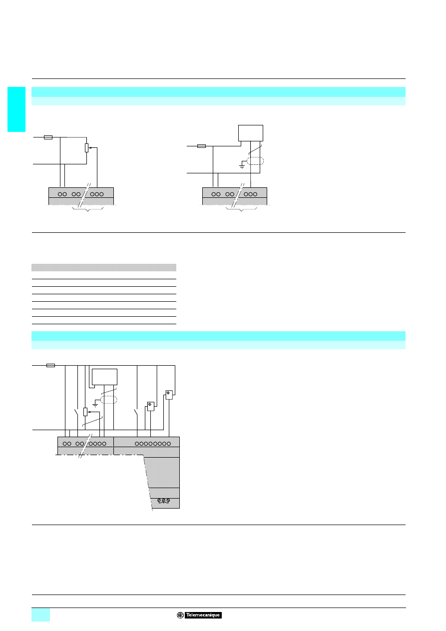
1/30
1
Schemes
(continued)
1
Zelio Logic smart relays
1
Compact and modular smart relays
Connection of smart relays on
5 supply (continued)
Analogue inputs
(1) 1 A quick-blow fuse or circuit-breaker.
(2) Ca: Analogue sensor / Ta: Analogue transmitter.
(3) Recommended values: 2.2 k
Ω / 0.5 W (10 kΩ max.).
(4) Screened cables, maximum length 10 m.
(5) Analogue inputs according to Zelio Logic to smart relay, see table below:
Smart relays
Analogue inputs
SR2
22221222
22
22
22D
IB…IE
SR2 A201BD
IB and IC
SR2 D201BD
IB and IC
SR2 B20
22
22
22
22D
IB…IG
SR2 E201BD
IB…IG
SR3 B10
2222BD
IB…IE
SR3 B26
22
22
22
22D
IB…IG
Connection of smart relays on
5 supply, with discrete I/O extension modules
SR3 B
111
111
111
111JD + SR3 XT111
111
111
111JD, SR3 B111
111
111
111BD + SR3 XT111
111
111
111BD
(1) 1 A quick-blow fuse or circuit-breaker.
(2) Ca: Analogue sensor / Ta: Analogue transmitter.
(3) Recommended values: 2.2 k
Ω / 0.5 W (10 kΩ max.).
(4) Screened cables, maximum length 10 m.
+
–
+
–
(1)
(3)
(5)
+
–
+
–
(1)
Ca / Ta
(2)
(5)
(4)
1 0-10 V
ANALOG.
+
–
(1)
(3)
Ca / Ta
(2)
QB QC
QD QE
QF QG
+ –
BN
BK
BL
BN
BK
BL
(4)
Warning: QF and QG: 5 A for SR3 XT141
11
11
11
11
Presentation:
pages 1/6 to 1/9
Functions :
pages 1/10 to 1/12
Characteristics:
pages 1/14 to 1/19
Curves :
pages 1/20 and 1/21
References:
pages 1/22 to 1/27
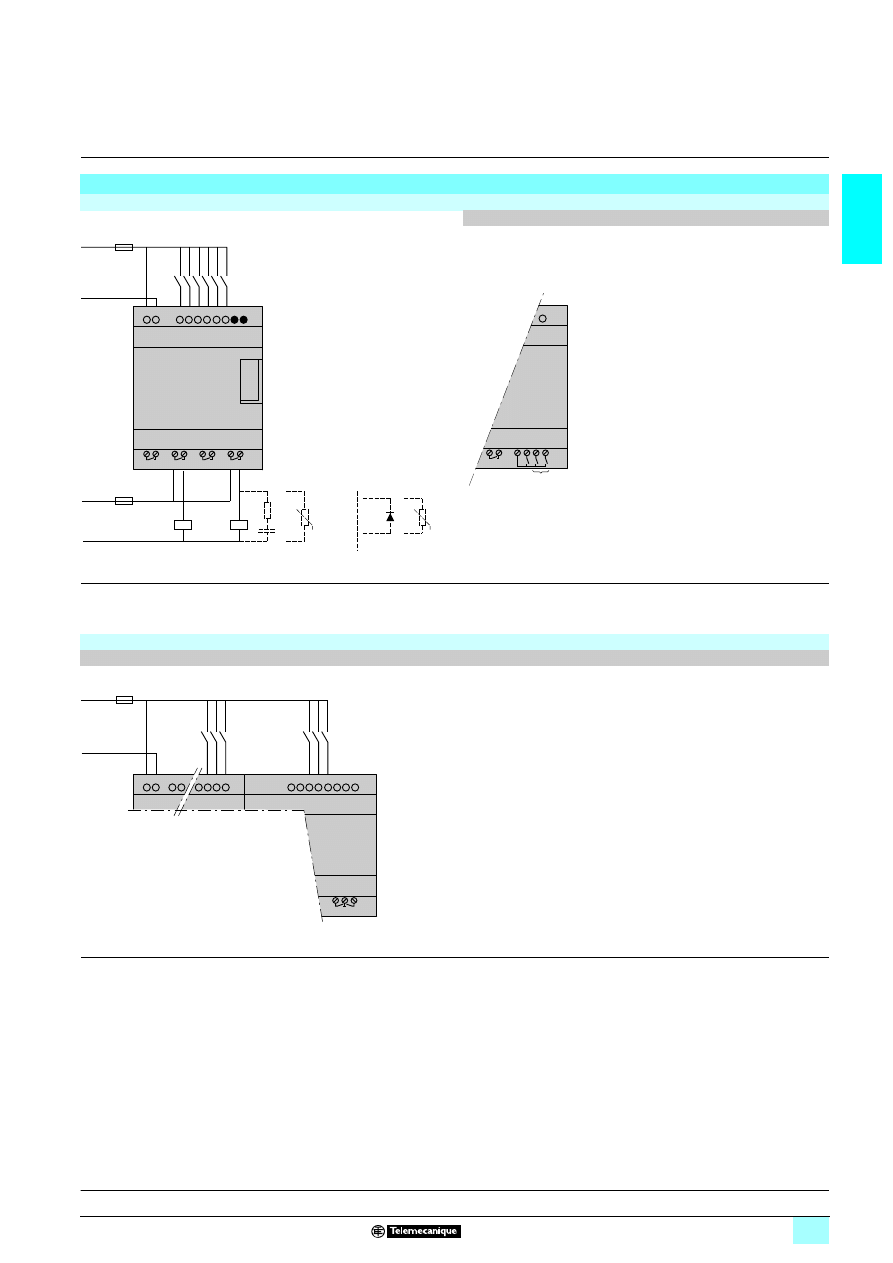
1/31
1
Schemes
(continued)
1
Zelio Logic smart relays
1
Compact and modular smart relays
Connection of smart relays on
3 supply
SR
15111
15111
15111
151111B, SR15111
15111
15111
151111FU
SR3 B261B and SR3 B261FU
(1) 1 A quick-blow fuse or circuit-breaker.
(2) Fuse or circuit-breaker.
(3) Inductive load.
(4) Q9 and QA: 5 A (max. current in terminal C: 10 A).
With discrete I/O extension module
SR3 B
222
222
222
222B + SR3 XT222
222
222
222B, SR3 B222
222
222
222FU + SR3 XT222
222
222
222FU
(1) 1 A quick-blow fuse or circuit-breaker.
L
L N
SRp ppppFU
a 100…240 V
50/60 Hz
SRp ppppB
a 24 V
N
(1)
Q1
Q2
Q3
Q4
z 12…240 V
50/60 Hz
c 12…24 V
L /
+
N /
–
z 12…240 V
50/60 Hz
c 12…24 V
(2)
(3)
U
(3)
U
or
–
6
Q7
C Q8 Q9 QA
IA IB IC ID IE IF IG
5 A
(4)
QB QC
QD QE
QF QG
+ –
L
N
(1)
Module
Extension
Warning: QF and QG: 5 A for SR3 XT141
11
11
11
11
Presentation:
pages 1/6 to 1/9
Functions :
pages 1/10 to 1/12
Characteristics:
pages 1/14 to 1/19
Curves :
pages 1/20 and 1/21
References:
pages 1/22 to 1/27
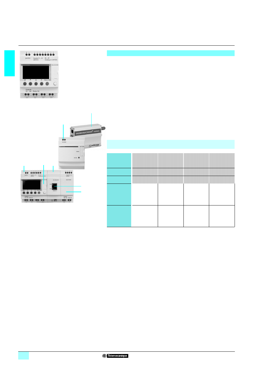
1/32
1
Presentation
1
Zelio Logic smart relays
1
Communication
In order to communicate with an intelligent environment, Zelio Logic smart relays and
their I/O extension and communication modules are equipped with various types of
communication port.
1 Compact and modular smart relays offer:
231 RS 232 serial port for connection of the PC, the Modem communication interface
or a memory cartridge slot.
1 Zelio Logic modular smart relay I/O extension and communication modules offer:
231 Modbus RS 485 port on communication module SR3 MBU01BD,
231 Ethernet 10/100 base T port supporting the Modbus TCP protocol on
communication module SR3 NET01BD.
These three ports allow Zelio Logic compact or modular smart relays to use 3
communication protocols:
1 Programming,
1 Modbus,
1 Ethernet.
Presentation
10
94
49
Smart relay
6
7
Communication ports on Zelio Logic smart relays and their I/O extension and
communication modules
Communication
port
Serial port
Modbus port on
communication
module
SR3 MBU01BD
Ethernet port on
communication
module
SR3 NET01BD
Modem
communication
interface port
Physical layer
RS 232
RS 485
10/100 base T
RS 232
Connector
Specific to Zelio RJ45
RJ45
Specific to Zelio
Compact
smart relays
All types
(connection and
isolation via cable
SR2 CBL01 or
SR2 USB01)
–
–
All modules with
clock
SR2 B
11111
SR2 E
11111
(see page
1/52)
Modular
smart relays
All types
(connection and
isolation via cable
SR2 CBL01 or
SR2 USB01)
All modules with
8724 V supply
SR3 B
111BD
All modules with
8724 V supply
SR3 B
111BD
All types
(see page
1/52)
00
00
03
-2
6
1
3
1
1
1
1
The order shown above must be observed when using
a Modbus slave or Ethernet server communication
module and a discrete or analogue I/O extension module.
An I/O extension module cannot be fitted before the
Modbus slave or Ethernet server communication module.
2
4
5
1
Modular smart relay
(10 or 26 I/O).
2
RS 232 serial port, Zelio Logic type
connector.
3
Modbus slave or Ethernet server
communication module.
4
RJ45 connector for Modbus or Ethernet
network connection.
5
I/O extension module: discrete
(6,10 or 14 I/O) or analogue (4 I/O).
6
Modem communication interface.
7
GSM (or analogue PSTN) Modem.
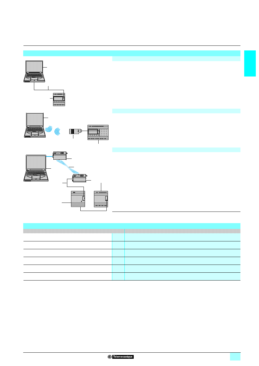
1/33
1
Description,
characteristics
1
Zelio Logic smart relays
1
Communication
Programming protocol
Description
Link by cable
1
Programming PC.
2
RS 232 serial link cable (SR2 CBL01) or USB cable (SR2 USB01) (1).
3
Zelio Logic compact or modular smart relay.
Wireless link
4
Programming PC with integrated Bluetooth technology (or Bluetooth adapter
VW3 A8115 for PC not equipped with Bluetooth technology) (1).
5
Bluetooth interface (SR2 BTC01) for Zelio Logic smart relay (1).
6
Zelio Logic compact or modular smart relay.
Link by Modem
7
Programming PC.
8
Modem interface connecting cable supplied with SR2 COM01 (2).
9
Modem for transmitting/receiving data SR2 MOD01 or SR2 MOD02 (2).
10
Telephone or radio link.
11
Communication interface SR2 COM01.
12
Zelio Logic compact or modular smart relay.
(1) See page 1/26.
(2) See page 1/52.
Serial link characteristics
Product type
All Zelio Logic smart relays
Flow rate
Kbit/s
115.2
Data bits
7
Stop bits
1
Parity
Pair
Physical layer
RS 232
Type of connector
Specific to Zelio Logic
1
3
2
4
5
6
7
9
10
9
12
8
11
52
41
07
52
41
06
52
41
08
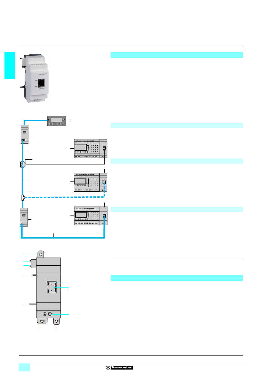
1/34
1
Presentation,
description
1
Zelio Logic smart relays
1
Communication
Modbus slave communication protocol
Presentation
The Modbus communication protocol is of the master/slave type.
Two exchange methods are possible:
1 Request/reply:
23The request from the master is addressed to a specific slave.
23The master waits for the reply to be returned by the slave polled.
1 Distribution:
23The master distributes a request to all the slave stations on the bus.
These stations execute the instruction without sending a reply.
Zelio Logic modular smart relays are connected to the Modbus network via the
Modbus slave communication module. This module is a slave that is not electrically
isolated.
The Modbus slave communication module must be connected to an SR3 B
666BD
modular smart relay, with a
5 24 V supply.
Configuration
The Modbus slave communication module can be configured:
1 independently, using the buttons on the smart relay (1).
1 on a PC, using “Zelio Soft 2” software, see page 1/9.
When using a PC, programming can be performed either in LADDER language or in
function block diagram (FBD) language, see pages 1/10 to 1/13.
Connection example
Modbus communication module
5
4
4
7
6
1
5bis
2
2
2
3
4
3
3
1
XBT N401 display unit.
2
Modular smart relay SR3 B
111BD.
3
Modbus communication module SR3 MBU01BD.
4
Modbus network (cables VW3 A8 306R
66).
5
Junction box TWD XCA T3RJ (polarisation and line end adapter activated).
5bis
Junction box TWD XCA T3RJ (line end adapter activated).
6
T-junction 170 XTS 04100.
7
T-junction VW3 A8 306TF
66.
Function description
1 The Modbus slave communication module is connected to a 2-wire or 4-wire
Modbus network (2).
1 The maximum length of the network is 1000 m (9600 bauds max., AWG 26).
1 A maximum of 32 slaves can be connected to the Modbus network, or a maximum
of 247 slaves with repeaters.
1 Line end adaptors must be fitted to both ends of the line
(1 nF/10 V, 120
Ω /0.25 W in series).
1 The line must be polarised (470 Ω /0.25 W resistors) (3).
1 The connection cable and its RJ45 male connectors must be screened.
1 The 7 terminal on the module must be connected directly to the protective earth
at one point on the bus.
(1) Programming from the front panel and buttons on the smart relay is only possible in LADDER
language.
(2) Please refer to installation instructions supplied with the product.
(3) The polarisation resistors must be managed by the master.
Description
Modbus slave communication module SR3 MBU01BD comprises:
1
Two retractable fixing lugs.
2
A Modbus network connection (RJ45 screened female connector).
3
A communication LED (COM).
4
A “Power on” LED (PWR).
5
A screw terminal block for the protective earth connection.
6
A spring for clip-on mounting on a 35 mm mounting rail.
7
Two locating pegs.
8
Two locating pegs for clip-on fixing.
COM
SR3 MBU01BD
MB485-V1
PWR
6
1
8
8
2
5
3
4
1
7
7
Characteristics:
page 1/35
Functions :
page 1/36
References :
page 1/40
Dimensions, mounting :
page 1/41
53
25
2
2
52
41
21
52
41
31
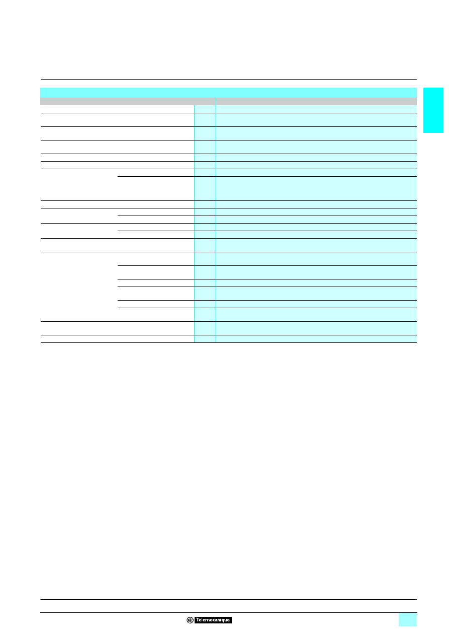
1/35
1
Characteristics
1
Zelio Logic smart relays
1
Communication
Modbus slave communication protocol
(1) Except for the configuration SR3 B
111BD + SR3 MBU01BD + SR3 XT43BD class A (class B:
work in progress).
Environment characteristics
Type
SR3 MBU01BD
Product certifications
UL, CSA, GL, C-TICK
Conformity with the
low voltage directive
Conforming to 73/23/EEC
EN (IEC) 61131-2 (open equipment)
Conformity with the
EMC directive
Conforming to 89/336/EEC
EN (IEC) 61131-2 (Zone B)
EN (IEC) 61000-6-2, EN (IEC) 61000-6-3 (1) and EN (IEC) 61000-6-4
Degree of protection
Conforming to IEC/EN 60529
IP 20 (terminal block)
IP 40 (front panel)
Overvoltage category
Conforming to IEC/EN 60664-1
3
Degree of pollution
Conforming to IEC/EN 61131-2
2
Ambient air temperature
around the device
Conforming to
IEC/EN 60068-2-1 and
IEC/EN 60068-2-2
Operation
°C
- 20... + 55 (+ 40 in non-ventilated enclosure)
Storage
°C
- 40... + 70
Max. relative humidity
Conforming to IEC/EN 60068-2-30
95% without condensation or dripping water
Maximum operating altitude
Operation
m
2000
Transport
m
3048
Mechanical resistance
Immunity to vibration
IEC/EN 60068-2-6, test Fc
Immunity to mechanical shock
IEC/EN 60068-2-27, test Ea
Resistance to
electrostatic discharge
Immunity to
electrostatic discharge
IEC/EN 61000-4-2, level 3
Resistance to HF interference
(immunity)
Immunity to
electromagnetic radiated fields
IEC/EN 61000-4-3
Immunity to fast transients
in bursts
IEC/EN 61000-4-4, level 3
Immunity to shock waves
IEC/EN 61000-4-5
Radio frequency
in common mode
IEC/EN 61000-4-6, level 3
Voltage dips and breaks (
6)
IEC/EN 61000-4-11
Immunity to damped
oscillation waves
IEC/EN 61000-4-12
Conducted and radiated
emissions
Conforming to EN 55022/11
(Group 1)
Class B (1)
Earthing
Yes (please refer to installation instructions supplied with the product).
Presentation, description :
page 1/34
Functions :
page 1/36
References :
page 1/40
Dimensions, mounting :
page 1/41
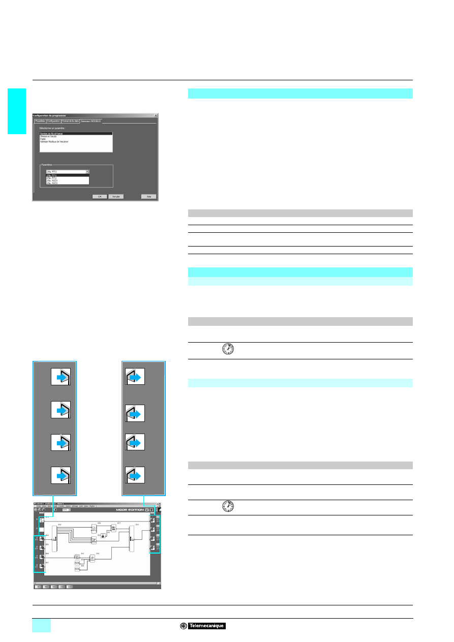
1/36
1
Functions
1
Zelio Logic smart relays
1
Communication
Modbus slave communication protocol
(1) Programming from the front panel and buttons on the smart relay is only possible in LADDER
language.
Parameter entry
Parameters can be entered either using “Zelio Soft 2” software or directly using the
buttons on the Zelio Logic smart relay (1).
When the “RUN” instruction is given, the Zelio Logic smart relay initialises the
Modbus slave communication module in a configuration previously defined in the
basic program.
The Modbus slave communication module has 4 parameters:
1 number of UART wires and format of the frames on the Modbus network,
1 transmission speed,
1 parity,
1 network address of the Modbus module.
The default parameter settings are as follows: 2-wire, RTU, 19 200 bauds, even
parity, address n° 1.
Parameter entry
Options
Number of wires
2 or 4
Frame format
RTU or ASCII
Transmission speed
in bauds
1200, 2400, 4800, 9600, 19 200, 28 800, 38 400, 57 600
Parity
None, even, odd
Network address
1 to 247
Software workshop
parameter entry window
Addressing of Modbus exchanges
LADDER programming
In LADDER mode, the 4 data words (16 bits) to be exchanged cannot be accessed
by the application. Transfers with the master are implicit and are effected in a way
that is totally transparent.
Modbus exchanges
Code
Number of words
Image of smart relay I/O
Read
03
4
Clock words Read/Write
16, 06 or 03
4
Status words
Read
03
1
Function block diagram (FBD) programming
In FBD mode, the 4 input data words (16 bits) (J1XT1 to J4XT1) and the 4 output
data words (O1XT1 to O4XT1) can be accessed by the application. Dedicated
function blocks make it possible to:
1 break down a ‘complete’ type input (16 bits) into 16 separate “bit” type outputs.
23example: break down a J1XT1 to J4XT1 type input and copy these status values
to discrete outputs.
1 make up a ‘complete’ type output (16 bits) from 16 separate “bit” type inputs.
23example: transfer the status value of the discrete inputs or the status of a function
to an O1XT1 to O4XT1 type output.
Modbus exchanges
Code
Number of words
Input words
Read/Write
16, 06 or 03
4
Output words
Read
03
4
Clock words Read/Write
16, 06 or 03
4
Status words
Read
03
1
J1
XT1
J2
XT1
J3
XT1
J4
XT1
3
7
2
3
7
2
3
7
2
3
7
2
01
XT1
02
XT1
03
XT1
04
XT1
0
9
3
4
0
9
3
4
0
9
3
4
0
9
3
4
Presentation, description :
page 1/34
Characteristics:
page 1/35
References :
page 1/40
Dimensions, mounting :
page 1/41
5
2
41
21
52
41
10
Input words
Output words
FDB program Editing window
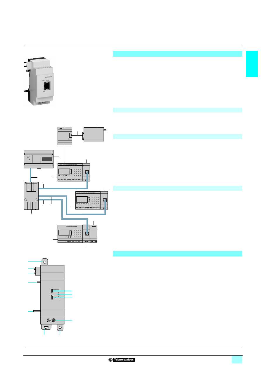
1/37
1
Presentation,
description
1
Zelio Logic smart relays
1
Communication
Ethernet server communication protocol
Presentation
Zelio Logic modular smart relays are connected to the Ethernet network via the
Ethernet server communication module.
Communication module SR3 NET01BD allows communication on the Ethernet
network under the Modbus TCP protocol.
The Ethernet server communication module must be connected to an SR3 B
666BD
modular smart relay, with a
5 24 V supply.
Configuration
The Ethernet server communication module is configured from a PC with "Zelio Soft"
software, see page 1/9.
On the PC, programming is effected in function block (FDB) language, see pages
1/12 and 1/13.
Connection example
1
Twido client, 40 I/O compact base controller TWD LCAE 40DRF.
2
Ethernet network (cables 490 NTW 000
66).
3
ConneXium 499 NES 251 00 Switch.
4
Zelio Logic modular smart relay SR3 B
666BD.
5
Communication interface SR2COM01.
6
Connecting cable SR2 CBL07 (supplied with the Modem communication
interface).
7
GSM (or analogue PSTN) Modem.
8
Ethernet server communication module SR3 NET01BD.
9
Analogue I/O extension module SR3 XT43BD.
Function description
1 The Ethernet server communication module is connected to a local LAN type
network.
1 The maximum cable length between 2 devices is 100 m.
1 The connection cable must be at least category 5, and its RJ45 male connectors
must be screened.
1 The 7 terminal must be connected directly to the protective earth.
Description
Ethernet server communication module SR3 NET01BD comprises:
1
Two retractable fixing lugs.
2
An Ethernet network connection (RJ45 screened female connector).
3
A communication LED (LK/ACT 10/100).
4
A status LED (STS).
5
A screw terminal block for the protective earth connection.
6
A spring for clip-on mounting on a 35 mm mounting rail.
7
Two locating pegs.
8
Two locating pegs for clip-on fixing.
Ethernet server
communication module
1
2
4
3
2
2
4
9
8
8
4
8
7
6
5
2
LK/ACT 10/100
SR3 NET01BD
STS
6
1
8
8
2
5
3
4
1
7
7
Characteristics:
page 1/38
Functions :
page 1/39
References :
page 1/40
Dimensions, mounting :
page 1/41
53
63
1
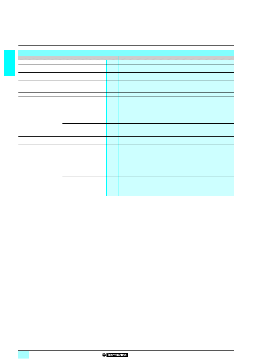
1/38
1
Characteristics
1
Zelio Logic smart relays
1
Communication
Ethernet server communication module
(1) Except for the configuration SR3 B
111BD + SR3 NET01BD + SR3 XT43BD class A
(class B: work in progress).
Environment characteristics
Type
SR3 NET01BD
Product certifications
UL, CSA, GL (pending), C-TICK (pending)
Conformity with the
low voltage directive
Conforming to 73/23/EEC
EN (IEC) 61131-2 (open equipment)
Conformity with the
EMC directive
Conforming to 89/336/EEC
EN (IEC) 61131-2 (Zone B)
EN (IEC) 61000-6-2, EN (IEC) 61000-6-3 (1) and EN (IEC) 61000-6-4
Degree of protection
Conforming to IEC/EN 60529
IP 20 (terminal block)
IP 40 (front panel)
Overvoltage category
Conforming to IEC/EN 60664-1
3
Degree of pollution
Conforming to IEC/EN 61131-2
2
Ambient air temperature
around the device
Conforming to
IEC/EN 60068-2-1 and
IEC/EN 60068-2-2
Operation
°C
0... + 55 (+ 40 in non-ventilated enclosure)
Storage
°C
- 40... + 70
Max. relative humidity
Conforming to IEC/EN 60068-2-30
95% without condensation or dripping water
Maximum operating altitude
Operation
m
2000
Transport
m
3048
Mechanical resistance
Immunity to vibration
IEC/EN 60068-2-6, test Fc
Immunity to mechanical shock
IEC/EN 60068-2-27, test Ea
Resistance to
electrostatic discharge
Immunity to
electrostatic discharge
IEC/EN 61000-4-2, level 3
Resistance to HF interference
(immunity)
Immunity to
electromagnetic radiated fields
IEC/EN 61000-4-3
Immunity to fast transients
in bursts
IEC/EN 61000-4-4, level 3
Immunity to shock waves
IEC/EN 61000-4-5
Radio frequency
in common mode
IEC/EN 61000-4-6, level 3
Voltage dips and breaks (
6)
IEC/EN 61000-4-11
Immunity to damped
oscillation waves
IEC/EN 61000-4-12
Conducted and
radiated emissions
Conforming to EN 55022/11
(Group 1)
Class B(1)
Earthing
Yes (please refer to installation instructions supplied with the product).
Presentation, description :
page 1/37
Functions :
page 1/39
References :
page 1/40
Dimensions, mounting :
page 1/41
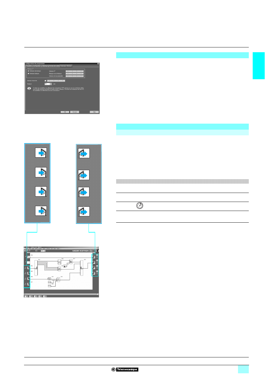
1/39
1
Functions
1
Zelio Logic smart relays
1
Communication
Ethernet server communication module
Parameter entry
Parameter entry must be carried out using “Zelio Soft 2” software.
When the “RUN” instruction is given, the Zelio Logic smart relay initialises the
Ethernet server communication module in a configuration previously defined in the
basic program.
The Ethernet server communication module has 6 parameters:
1 type of addressing (dynamic or static).
1 IP address,
1 sub-network mask,
1 gateway address,
1 reserved address,
1 time out.
Addressing of Ethernet exchanges
Function block diagram (FBD) programming
In FBD mode, the 4 input data words (16 bits) (J1XT1 to J4XT1) and the 4 output
data words (O1XT1 to O4XT1) can be accessed by the application. Dedicated
function blocks make it possible to:
1 break down a ‘complete’ type input (16 bits) into 16 separate “bit” type outputs.
23example: break down a J1XT1 to J4XT1 type input and copy these status values
to discrete outputs.
1 make up a ‘complete’ type output (16 bits) from 16 separate “bit” type inputs.
23example: transfer the status value of the discrete inputs or the status of a function
to an O1XT1 to O4XT1 type output.
Ethernet exchanges
Code
Number of words
Input words
Read/Write
16, 06 or 03
4
Output words
Read
03
4
Clock words Read/Write
16, 06 or 03
4
Status
words
Read
03
1
Ethernet communication module configuration window
J1
XT1
J2
XT1
J3
XT1
J4
XT1
3
7
2
3
7
2
3
7
2
3
7
2
01
XT1
02
XT1
03
XT1
04
XT1
0
9
3
4
0
9
3
4
0
9
3
4
0
9
3
4
Presentation, description :
page 1/37
Characteristics:
page 1/38
References :
page 1/40
Dimensions, mounting :
page 1/41
Input words
Output words
FDB program Editing window
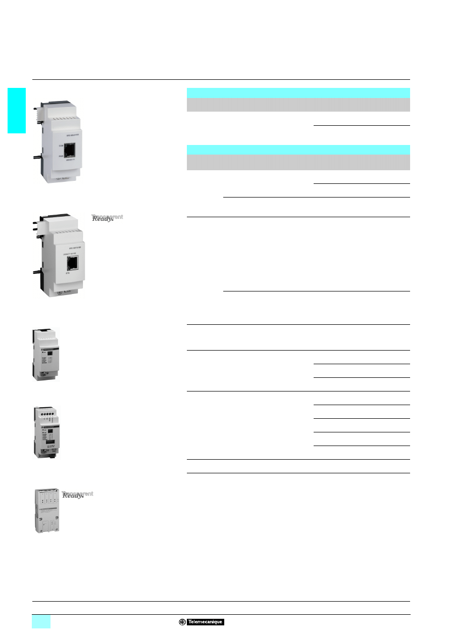
1/40
1
References
1
Zelio Logic smart relays
1
Communication
8 Available: 1
st
quarter 2007
Modbus slave and Ethernet server communication modules
For use with
Network
Reference
Weight
kg
Modular smart relays
SR3 B
22
22
22
221BD and SR3 B22
22
22
222BD (1)
Modbus
SR3 MBU01BD
0.110
Ethernet
SR3 NET01BD
(2)
,
(3)
0.110
Connection accessories
Accessory
Description
Network
Length
Reference
Weight
m
kg
T-junctions
372 x RJ45 connectors
371 cable with integrated
RJ45 connector
Modbus
0.3
VW3 A8 306TF03
0.190
1
VW3 A8 306TF10
0.210
372 x RJ45 female
connectors
371 x RJ45 male connector
Modbus
Without
cable
170 XTS 04100
0.020
Junction
boxes
37Screw terminal block
for main cable
371 x RJ45 connector
for tap link
37Isolation of RS 485
serial link
23
Polarisation and
line end
adapter
23
Supply
5
24 V
23
Mounting on 35 mm
9
rail
Modbus
–
TWD XCA ISO
8
0.100
373 x RJ45 connectors
37Polarisation and line
end adapter
23
Mounting on
3
35 mm
9
rail
Modbus
–
TWD XCA T3RJ
8
0.080
Line end
adapter
For RJ45 connector
R = 120
Ω, C = 1 nf
Modbus
–
VW3 A8306RC
0.200
RS 485
cables
2 x RJ45 connectors
Modbus
0.3
VW3 A8306R03
0.030
1
VW3 A8306R10
0.050
3
VW3 A8306R30
0.150
Straight
shielded
twisted pair
cable
2 x RJ45 connectors
Ethernet 2
490 NTW 000 02 (4)
–
5
490 NTW 000 05 (4)
–
12
490 NTW 000 12 (4)
–
40
490 NTW 000 40 (4)
–
80
490 NTW 000 80 (4)
–
conneXium
switch
–
Ethernet
499 NES 251 00
0.190
(1) Compatible with SR3 B
11
11
11
112BD featuring hardware version “H1.0.01”, available since June
2005.
(2) Can only be used in FBD language.
(3) Can only be used with "Zelio Soft 2" software version
2 V 4.1.
(4) Cable conforming to EIA/TIA-568 standard category 5 and IEC 1180/EN 50 173, class D.
For UL and CSA 22.1 approved cables, add the letter U at the end of the reference.
499 NES 251 00
SR3 MBU01BD
SR3 NET01BD
TWD XCA T3RJ
TWD XCA ISO
Presentation, description :
pages 1/34 to 1/37
Characteristics:
pages 1/35 to 1/38
Functions :
pages 1/36 to 1/39
Dimensions, mounting :
page 1/41
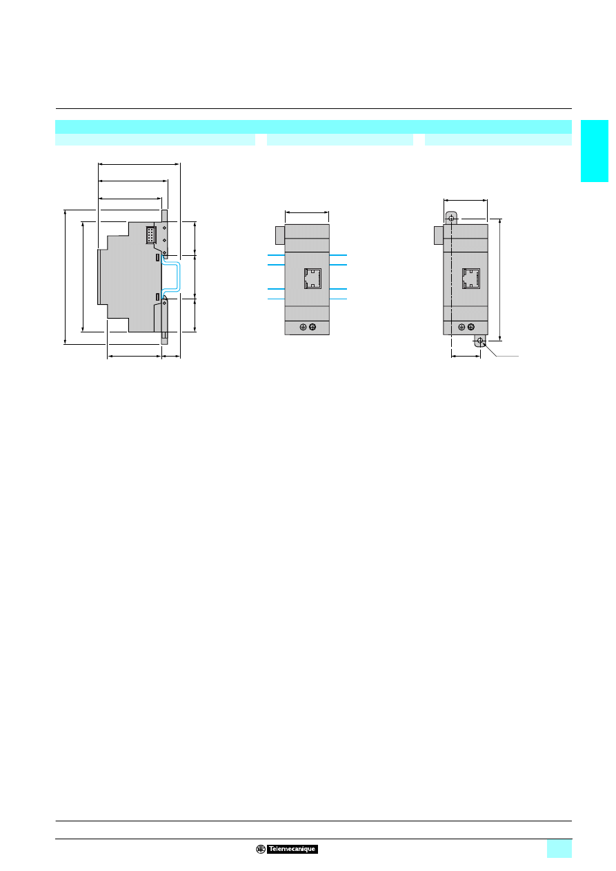
1/41
1
Dimensions,
mounting
1
Zelio Logic smart relays
1
Communication
Communication modules SR3
66601BD
Common side view
Rail mounting
Screw mounting
(retractable lugs)
57
52,5
70
44
15
90
35
27.5
27.5
108
35
25
35
100
2 x Ø4
Presentation, description :
pages 1/34 to 1/37
Characteristics:
pages 1/35 to 1/38
Functions :
pages 1/36 to 1/39
References:
page 1/40
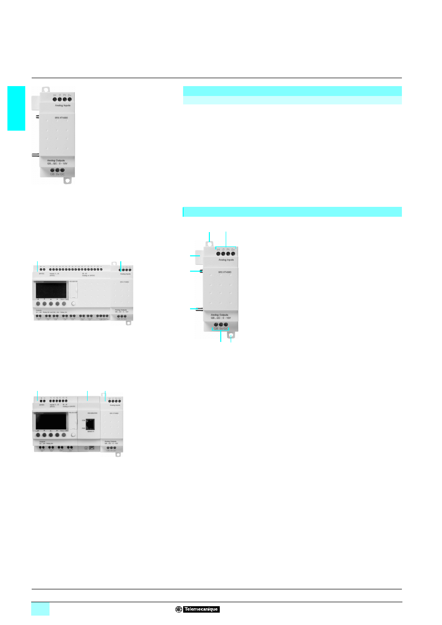
1/42
1
Presentation,
description
1
Zelio Logic smart relays
1
Analogue I/O extension modules
Presentation
Modular smart relays and analogue I/O extension modules
To improve performance and flexibility, Zelio Logic modular smart relays can be fitted
with analogue I/O extension modules with 10-bit resolution.
The inputs accept 0-10 V, 0-20 mA and Pt 100 type signals.
Using a Zelio Logic modular smart relay with
5 24 V supply in conjunction with an
analogue 4 I/O extension module makes it possible to obtain up to 30 I/O, including
8 analogue inputs and 2 analogue outputs.
The analogue I/O extension module must be connected to an SR3
666BD modular
smart relay with a
5 24 V supply.
Description
The analogue I/O extension module has the
following on its front panel:
1
Two retractable fixing lugs.
2
Terminals for connection of the inputs.
3
Terminals for connection of the outputs.
4
A connector for connection to the smart
relay (powered via the smart relay).
5
Locating pegs.
53
62
79
Analogue I/O
extension modules
52
41
27
1
2
1
Modular smart relay
(10 or 26 I/O)
2
Analogue I/O extension module
(4 I/O)
52
41
28
1
2
1
Modular smart relay
(10 or 26 I/O)
2
Modbus or Ethernet communication modules
3
Analogue I/O extension module (4 I/O)
3
1
2
5
1
3
5
4
Characteristics:
page 1/43
References, dimensions :
page 1/44
Schemes:
page 1/45
Combination of modular smart relays with
communication and I/O extension modules
1
1
1
1
The order shown above must be observed when using
a network communication module and an analogue I/O
extension module.
An I/O extension module cannot be fitted before the
network communication module.
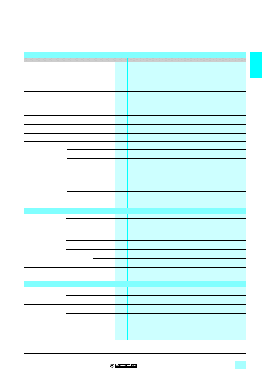
1/43
1
Characteristics
1
Zelio Logic smart relays
1
Analogue I/O extension modules
(1) Except for configuration SR3 B
111BD + SR3 MBU01BD + SR3 XT43BD
or SR3 B
111BD + SR3 NET01BD + SR3 XT43BD class A (class B: work in progress).
General environment characteristics
Type
SR3 XT43BD
Product certifications
UL, CSA, C-Tick, GL (pending)
Conformity with the
low voltage directive
Conforming to 73/23/EEC
EN (IEC) 61131-2 (open equipment)
Conformity with the
EMC directive
Conforming to 89/336/EEC
EN (IEC) 61131-2 (Zone B)
EN (IEC) 61000-6-2, EN (IEC) 61000-6-3 (1) and EN (IEC) 61000-6-4
Degree of protection
Conforming to IEC/EN 60529
IP 20 (terminal block), IP 40 (front panel)
Overvoltage category
Conforming to IEC/EN 60664-1
3
Degree of pollution
Conforming to IEC/EN 61131-2
2
Ambient air temperature
around the device
(conforming to IEC/EN 60068-2-1
and IEC/EN 60068-2-2
Operation
°C
- 20... + 55 (+ 40 in enclosure)
Storage
°C
- 40... + 70
Maximum relative humidity
Conforming to IEC/EN 60068-2-30
95% without condensation or dripping water
Maximum operating
altitude
Operation
m
2000
Transport
m
3048
Mechanical resistance
Immunity to vibration
IEC/EN 60068-2-6, test Fc
Immunity to mechanical shock
IEC/EN 60068-2-27, test Ea
Resistance to
electrostatic discharge
Immunity to electrostatic discharge
IEC/EN 61000-4-2, level 3
Resistance to HF
interference
(immunity)
Immunity to electromagnetic
radiated fields
IEC/EN 61000-4-3
Immunity to fast transients in bursts
IEC/EN 61000-4-4, level 3
Immunity to shock waves
IEC/EN 61000-4-5
Radio frequency in common mode
IEC/EN 61000-4-6, level 3
Voltage dips and breaks (
6)
IEC/EN 61000-4-11
Immunity to damped oscillation
waves
IEC/EN 61000-4-12
Conducted and
radiated emissions
Conforming to EN 55022/11
(Group 1)
Class B (1)
Connection capacity
to screw terminals
Flexible cable with cable end
mm
2
1 conductor: 0.25...2.5, cable: AWG 24...AWG 14
2 conductors: 0.25...0.75, cable: AWG 24...AWG 18
Semi-solid cable
mm
2
1 conductor: 0.2...2.5, cable: AWG 25...AWG 14
Solid cable
mm
2
1 conductor: 0.25...2.5, cable: AWG 25...AWG 14
2 conductors: 0.2...1.5, cable: AWG 24...AWG 16
Tightening torque
N.m
0.5 (tightened using Ø 3.5 mm screwdriver)
54analogue input characteristics
(inputs IH, IJ and Pt)
Analogue inputs
Application
8 0-10 V
8 0-20mA
Pt100
Assignable inputs
IH and IJ
IH and IJ
IJ
Input range
8 0...10 V
8 0...20 mA
- 25 °C...125 °C
Input impedance
Ω
18 k
247
–
Maximum non destructive value
8 30 V
8 30 mA
–
Value of LSB
9.8 mV
20 μΑ
0,15 °C
Input type
Common mode
Pt100 probe - IEC 751 3-wire
Conversion
Resolution
10 bits on the input range
Conversion time
Smart relay cycle time
Precision
at 25 °C
± 1 %
± 1.5 °C
at 55 °C
± 1 %
± 1.5 °C
Repeat accuracy
at 25 °C
< ± 1 %
< ± 0.3 °C
Isolation
Between analogue channel and supply
None
Cabling distance
m
10 maximum, with screened cable
Protection
Against reversed polarity
Yes
–
5 analogue output characteristics
(QB, QC)
Analogue outputs
Output range
V
8 0..0.10
Type of load
Resistive
Maximum load
mA
10
Value of LSB
mV
9.8
Conversion
Resolution
10 bits on the output range
Conversion time
Smart relay cycle time
Precision
at 25 °C
± 1% of the full scale value
at 55 °C
± 1% of the full scale value
Repeat accuracy
at 55 °C
< ± 1%
Isolation
Between analogue channel and supply
None
Cabling distance
m
10 maximum, with screened cable
Built-in protection
Against short-circuits
Yes
Presentation, description :
page 1/42
References, dimensions :
page 1/44
Schemes:
page 1/45
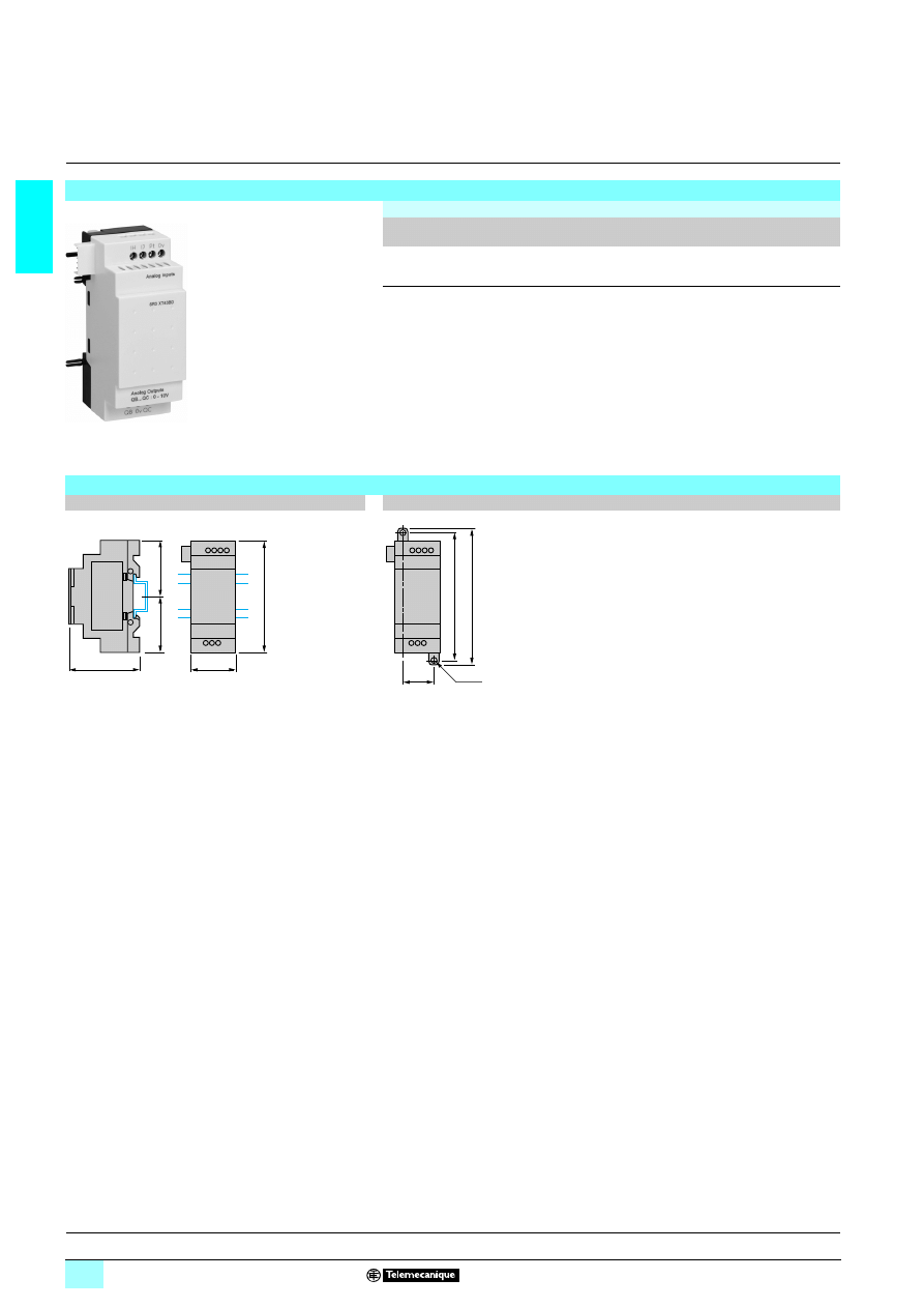
1/44
1
References,
dimensions
1
Zelio Logic smart relays
1
Analogue I/O extension modules
Analogue I/O extension modules
Supply
4
4
4
4 24 V (via smart relays SR3 B111
111
111
111BD)
Number
of I/O
Number
of inputs
Including
0 - 10 V
Including
0 - 20 mA
Including
Pt100
0-10 V
output
Reference
Weight
kg
4
2 (1)
2 max
2 max
1 max
2
SR3 XT43BD(2),(3)
0.110
(1) See page 1/45.
(2) Can only be used with "Zelio Soft 2" software version
5V 3.1.
(3) Can only be used in FBD language.
SR3 XT43BD
53
49
45
Dimensions
Mounting on 35 mm
6
6
6
6 rail
Screw fixing (retractable lugs)
35,5
=
=
59,5
25
100
107,6
90
2xØ4
Presentation, description :
page 1/42
Characteristics:
page 1/43
Schemes:
page 1/45
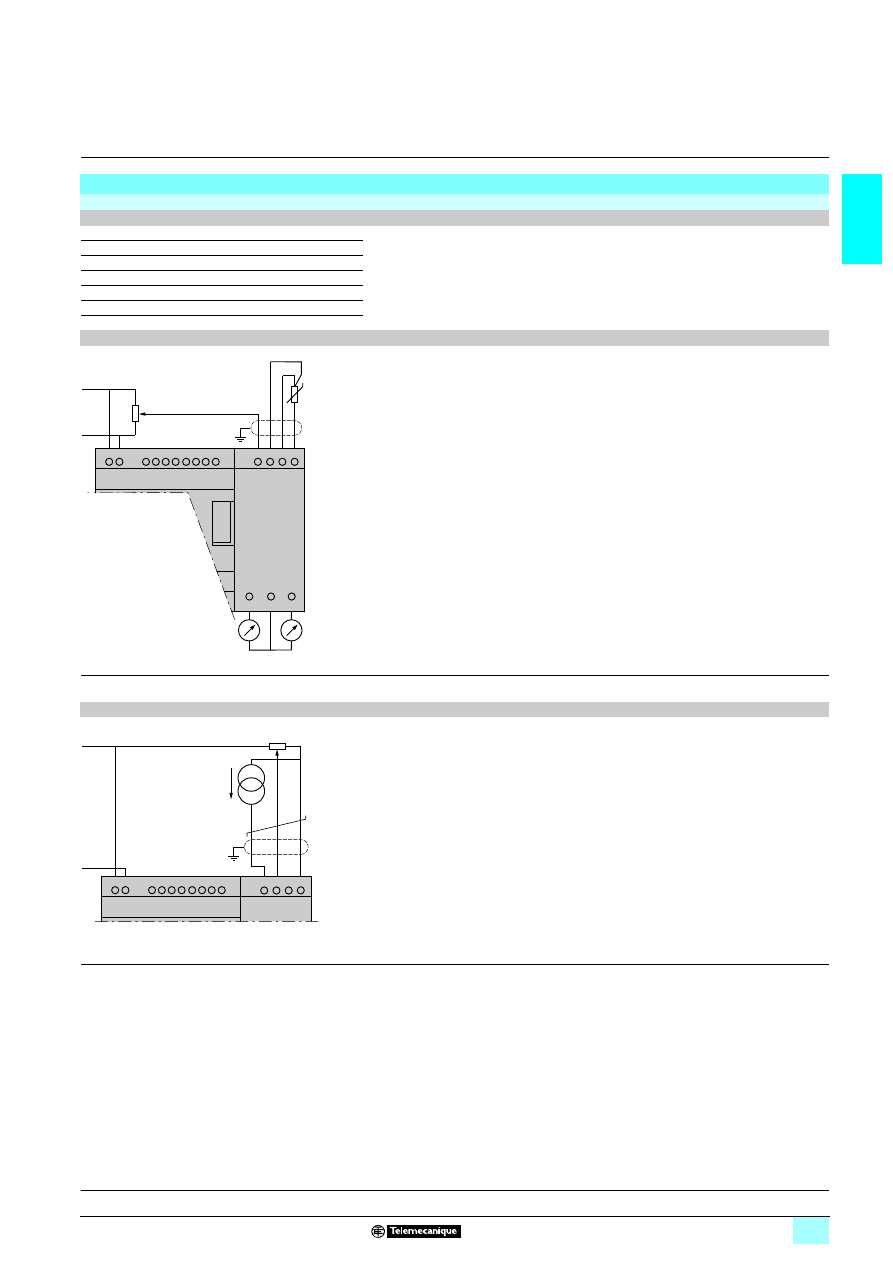
1/45
1
Schemes
1
Zelio Logic smart relays
1
Analogue I/O extension modules
Connection of smart relays on
5 supply, with analogue I/O extension module
SR3 B
111
111
111
111BD + SR3 XT43BD
Connection alternatives
0 - 10 V
0 - 20 mA
Pt100
2
0
0
1
1
0
0
2
0
1
0
1
0
1
1
Application example with 1 x 0 - 10 V input and 1 x Pt100 input
(1) Screened cables, maximum length 10 m.
Application example with 1 x 0 - 20 mA input and 1 x 0 - 10 V input
(1) Screened cables, maximum length 10 m.
+
–
IH IJ Pt
QB
0V
QC
0V
+
–
Q1
Q2
Q3
Q4
(1)
+
–
+
–
IH IJ Pt 0V
(1)
0
- 20
mA
Presentation, description :
page 1/42
Characteristics:
page 1/43
References, dimensions :
page 1/44
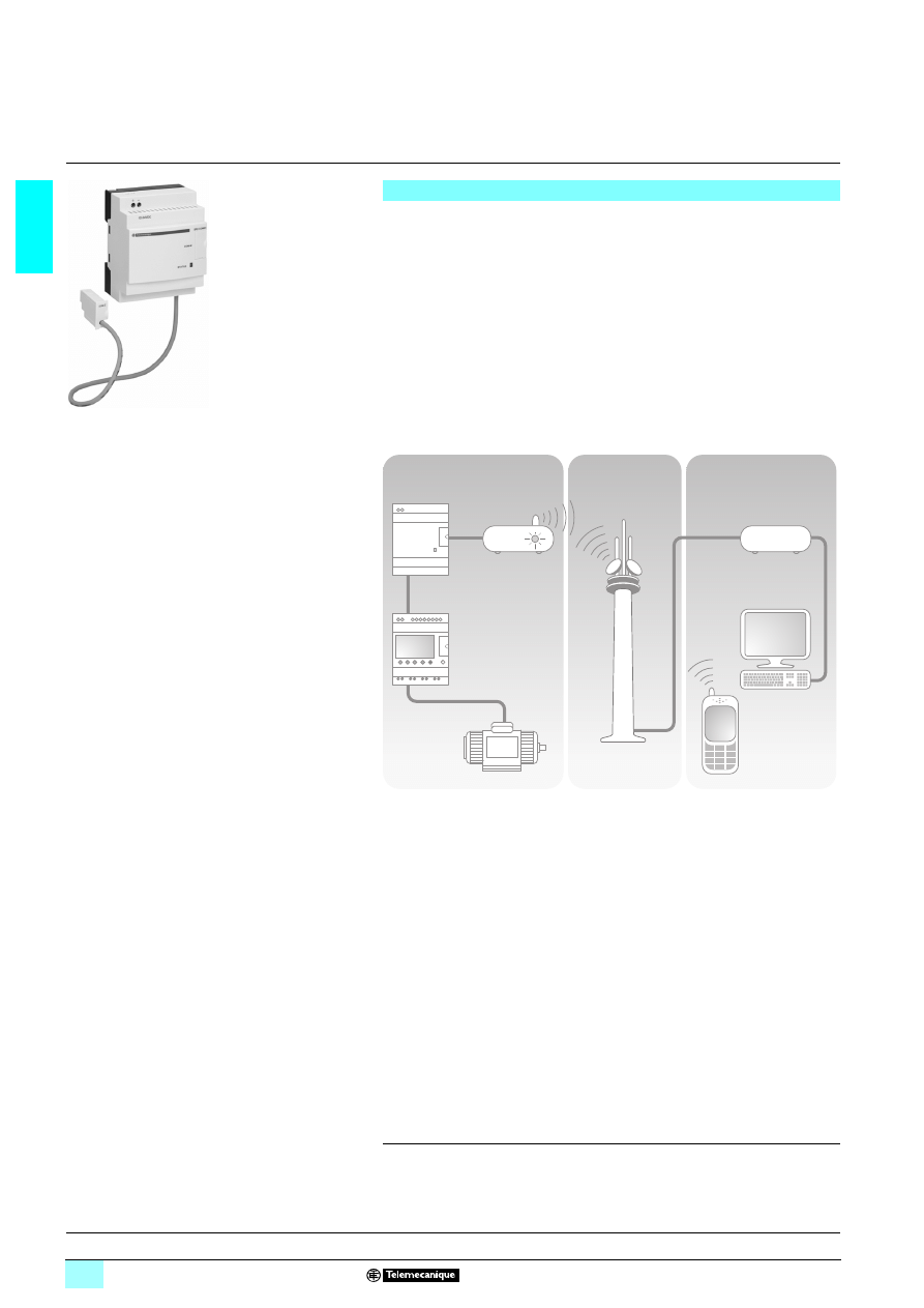
1/46
1
Presentation
1
Zelio Logic smart relays
1
Modem communication interface
The communication products in the Zelio Logic range are primarily designed for
monitoring or remote control of machines or installations which operate without
personnel.
Examples:
1 monitoring of lift pumps, livestock premises (ventilation, food level, etc.),
refrigeration units, car-washes,
1 alarm in the event of failure of industrial or domestic heating boilers,
1 remote control of lighting: car parks, warehouses,
1 remote control and monitoring of escalators in large stores, in the transport sector,
1 refuse compactor full alert.
The communication range comprises:
1 a communication interface connected between a smart relay and a Modem,
1 Modems: GSM (1) or analogue (PSTN) (2),
1 “Zelio Logic Alarm” software.
The system comprises:
1 a Remote station, machine or installation to be monitored
1
:
control is achieved using a Zelio Logic smart relay with clock from the SR
6 B66666
or SR2 E
66666
2
range, via its inputs and outputs. The smart relay is connected via
a communication interface
3
to a GSM (1) type Modem
4
, or, when a telephone line
is available nearby, to an analogue PSTN modem (2),
1 the GSM
5
or
analogue PSTN
6
Transmission Network provided by different
telecommunication operators,
1 a monitoring or control Receiving device, which may be one of the following:
23a PC
7
fitted with an analogue PSTN Modem
8
or a GSM modem,
23or a GSM telephone
9
.
Nota : the majority of Modems built into PCs can be used.
Various combinations are possible between the types of Modem used on the Remote
station and the type of Receiving device (PC + Modems or GSM telephone).
The type of architecture selected will therefore depend mainly on:
1 whether or not an analogue telephone line is available,
1 whether or not it is necessary to send SMS messages.
see page 1/49.
Presentation
Modem
communication interface
52
30
83
1
2
3
4
5
7
8
9
6
Remote station
Transmission
network
Receiving equipment
Communication
interface
GSM
or
Analogue
PSTN
Modem
Zelio Logic
smart relay
Analogue
PSTN
or
GSM Modem
(6) Global System Mobile.
(7) Public Switched Telephone Network.
Functions, setting-up:
pages 1/48 and 1/49
Characteristics:
pages 1/50 and 1/51
References:
page 1/52
Dimensions:
page 1/53
Connections:
pages 1/54 and 1/55
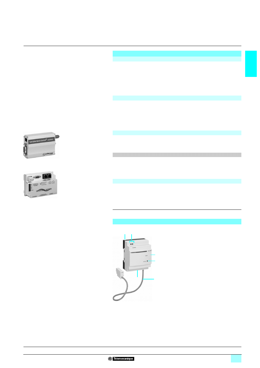
1/47
1
Presentation
(continued)
description
1
Zelio Logic smart relays
1
Modem communication interface
The smart relay, as on an independent machine or installation, is used for control (1).
It contains the application program created using “Zelio Soft 2” software.
The smart relay may be selected from the various models in the Zelio Logic range:
1 for all supply voltages,
1 with 10, 12, 20 or 26 I/O (up to 40 I/O with discrete extension module),
1 with or without display,
1 with clock.
The firmware version of the smart relay must be V3 or above.
The Modem communication interface allows messages, telephone numbers and
calling conditions to be stored.
When the calling conditions are met, the messages, as well as any values to be sent,
are date-stamped and stored in the interface.
The Modem communication interface scales analogue values to the physical values
(degrees, bar, Pascal, etc.) required by the user.
Either GSM or analogue PSTN type Modems can be used on both the Remote
station and PC type Receiving devices (when the PC is not fitted with an internal
Modem).
In order to exploit all the capabilities associated with Modem communication, the
Modem(s) must be fitted with DATA type SIM cards. VOICE type SIM cards may be
used but some functions will not be available. See table on page 1/49.
This software makes it possible to:
1 receive, classify and export alarm messages,
1 read or remotely force the status of program elements (inputs, outputs, control
relays, timing or counting values, etc.),
1 send control instructions (RUN, STOP, setting the time of the smart relay, etc.),
1 send specific instructions (modifying access rights, recipients, etc.).
Presentation
(continued)
Smart relay (Remote station)
Modem communication interface (Remote station)
Modems
GSM Modem
53
55
23
Analogue PSTN Modem
53
55
22
GSM Modem
“Zelio Logic Alarm” alarm management software (PC type Receiving device)
(1) Zelio Logic smart relays, see pages 1/6 to 1/25.
Functions, setting-up:
pages 1/48 and 1/49
Characteristics:
pages 1/50 and 1/51
References:
page 1/52
Dimensions:
page 1/53
Connections:
pages 1/54 and 1/55
Description
The communication interface Zelio Logic SR2 COM01 comprises:
1
2
3
4
5
6
Retractable fixing lugs.
A
5 12…24 V supply terminal block.
A slot for connection to the Modem or the PC.
An interface status LED indicator.
A connecting cable to the smart relay.
A spring for clip-on mounting on a 35 mm
mounting rail.
1
2
3
5
4
6

1/48
1
Functions
1
Zelio Logic smart relays
1
Modem communication interface
This function makes it possible to send an alarm message to a Receiving device.
When the calling condition is met, a message is sent to one or several telephone
numbers or e-mail addresses.
Types of message:
1 alarm message to a PC with Modem and “Zelio Logic Alarm” software,
1 “SMS” message (1) to a GSM telephone,
1 e-mail via SMS (1) (2).
One or all of the solutions can be selected simultaneously.
The Remote station to be monitored initiates the call.
The telephone line is only used while the alarm message is being transmitted.
Up to 28 messages can be used.
These messages consist of:
1 a 160 character text, which may contain a discrete and/or analogue value
(counting values, analogue input voltages that can be scaled, etc.).
1 1 to 10 recipient telephone numbers/e-mail addresses.
This function allows the status or the value of a program element to be modified from
the Receiving device.
The operator initiates the call using the Receiving device (PC or GSM telephone). It
is then possible to force the status of the discrete and/or analogue value of each of
the 28 messages.
This function enables use of the Transfer, Monitoring and Diagnostics modes
available in “Zelio Soft 2”, via the Transmission network instead of the physical link
(cable SR2 USB01 or SR2 CBL01) between the product (Remote station) and the
PC (Receiving device) .
It is then possible to:
1 transfer a program created on a PC station to the Remote station,
1 transfer a program installed on the Remote station to the PC station,
1 modify, from the PC, the receiving device telephone numbers/e-mail addresses,
and the alarm sending conditions,
1 update the firmware in the smart relay and the Modem communication interface,
1 display and modify discrete and analogue values,
1 perform diagnostics on the smart relay and on the Modem communication
interface.
(1) Requires the use of a GSM Modem on the Remote station side.
(2) Verify with the Transmission network operator that the e-mail by SMS service is available.
Functions
Sending of alarms
Message parameter entry window
Receipt of instruction
Remote dialogue using “Zelio Soft 2”
Presentation, description :
pages 1/46 and 1/47
Characteristics:
pages 1/50 and 1/51
References:
page 1/52
Dimensions:
page 1/53
Connections:
pages 1/54 and 1/55
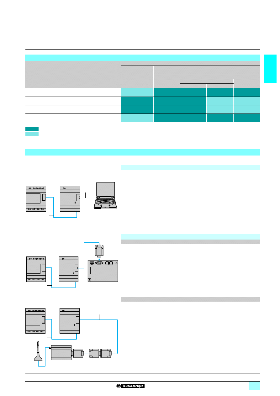
1/49
1
Functions
(continued),
setting-up
1
Zelio Logic smart relays
1
Modem communication interface
Setting-up of the installation or the machine to be monitored involves 2 steps:
1
Interface cable
marked COM-Z
2
Cable SR2 USB01 or SR2 CBL01.
After having powered-up the smart relay and the interface, the application program
can be transferred in order to simultaneously:
1 load the automation system program into the smart relay,
1 load the alarm conditions, messages and telephone numbers/e-mail addresses
into the interface.
This operation can also be carried out remotely using “Transfer” mode, after having
made the operating connections described below.
1
Program loading using memory cartridges SR2 MEM01 or SR2 MEM02 is
incompatible with Modem communication interface SR2 COM01.
1
Interface cable marked COM-Z.
2
Cable SR2 CBL07 included with the interface.
1
Interface cable marked COM-Z.
2
Cable SR2 CBL07 included with the interface.
3
SUB-D 9/SUB-D 15 cable included with the Modem
4
Antenna and cable included with the Modem.
Functions available depending on the hardware architecture and/or type of SIM card
Function
Remote station device
Analogue PSTN
Modem
GSM Modem
Type of SIM card
DATA
DATA VOICE
VOICE
DATA N°
VOICE N°
Send alarm/receive instruction with GSM telephone
Send alarm/receive instruction with PC
running “Zelio Logic Alarm” software (1)
Transfer program
Update firmware Monitoring (1)
Send alarm to e-mail address
Functions available
Functions not available
Nota : Instructions cannot be transmitted by e-mail.
(1) When using a GSM Modem on the PC side, the SIM card must have a DATA number.
Installation set-up
Connection for programming the smart relay and the interface
SR2 COM01
1
2
Smart relay
Communication
interface
PC
Operating connections
PSTN analogue modem
SR2 COM01
1
2
SR2 MOD01
Smart relay
Communication
interface
Analogue PSTN Modem
GSM Modem
SR2 COM01
1
2
3
4
SR2 COM01
Communication
interface
GSM Modem
Smart relay
Presentation, description :
pages 1/46 and 1/47
Characteristics:
pages 1/50 and 1/51
References:
page 1/52
Dimensions:
page 1/53
Connections:
pages 1/54 and 1/55
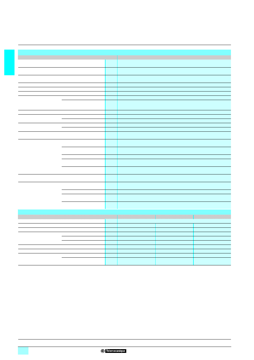
1/50
1
Characteristics
1
Zelio Logic smart relays
1
Modem communication interface
Communication interface environment characteristics
Interface type
SR2 COM01
Product certifications
UL, CSA, C-Tick
Conformity with the
low voltage directive
Conforming to 73/23/EEC
EN (IEC) 61131-2 (open equipment)
Conformity with the
EMC directive
Conforming to 89/336/EEC
EN (IEC) 61131-2 (Zone B)
EN (IEC) 61000-6-2, EN (IEC) 61000-6-3 and EN (IEC) 61000-6-4
Degree of protection
Conforming to IEC/EN 60529
IP 20 (terminal block), IP 40 (front panel)
Overvoltage category
Conforming to IEC/EN 60664-1
3
Degree of pollution
Conforming to IEC/EN 61131-2
2
Ambient air temperature
around the device
conforming to IEC/EN 60028-2-1
and IEC/EN 60068-2-2
Operation
°C
- 20...+ 55 (+ 40 in non-ventilated enclosure)
Storage
°C
- 40...+ 70
Maximum relative humidity
Conforming to IEC/EN 60068-2-30
95% without condensation or dripping water
Maximum operating altitude
Operation
m
2000
Transport
m
3048
Mechanical resistance
Immunity to vibration
IEC/EN 60068-2-6, test Fc
Immunity to mechanical shock
IEC/EN 60068-2-27, test Ea
Resistance to
electrostatic discharge
Immunity to electrostatic
discharge
IEC/EN 61000-4-2, level 3
Resistance to HF interference
(immunity)
Immunity to electromagnetic
radiated fields
IEC/EN 61000-4-3
Immunity to fast transients in
bursts
IEC/EN 61000-4-4, level 3
Immunity to shock waves
IEC/EN 61000-4-5
Radio frequency in common
mode
IEC/EN 61000-4-6, level 3
Immunity to damped oscillation
waves
IEC/EN 61000-4-12
Conducted and
radiated emissions
Conforming to EN 55022/11
(Group 1)
Class B
Connection capacity
to screw terminals
Flexible cable with cable end
mm
2
1 conductor: 0.25...2.5, cable: AWG 24...AWG 14
2 conductors: 0.25...0.75, cable: AWG 24...AWG 18
Semi-solid cable
mm
2
1 conductor: 0.2...2.5, cable: AWG 25...AWG 14
Solid cable
mm
2
1 conductor: 0.2...2.5, cable: AWG 25...AWG 14
2 conductors: 0.2...1.5, cable: AWG 24...AWG 16
Tightening torque
N.m
0.5 (tightened using Ø 3.5 mm screwdriver)
Supply characteristics
Interface type
SR2 COM01
SR2 MOD01
SR2 MOD02
Nominal voltage
V
8 12…24
Voltage limits
V
8 10…28.8
8 10…30
8 5.5…32
Maximum ripple
5 %
–
–
Nominal current
8 12 V
mA
30
140
125
8 24 V
mA
30
70
60
Current peak on power-up
mA
550
9600
2100 on 5.5 V
Power dissipated
W
1.1
1.7
1.5
Micro-breaks
Permissible duration
1 ms. repeated 20 times
–
–
Protection
Integrated
Against reversed polarity
–
–
To be provided externally
A
1 A fuse
–
Supplied with 2.5 A fuse
Presentation, description :
pages 1/46 and 1/47
Functions, setting-up:
pages 1/48 and 1/49
References:
page 1/52
Dimensions:
page 1/53
Connections:
pages 1/54 and 1/55
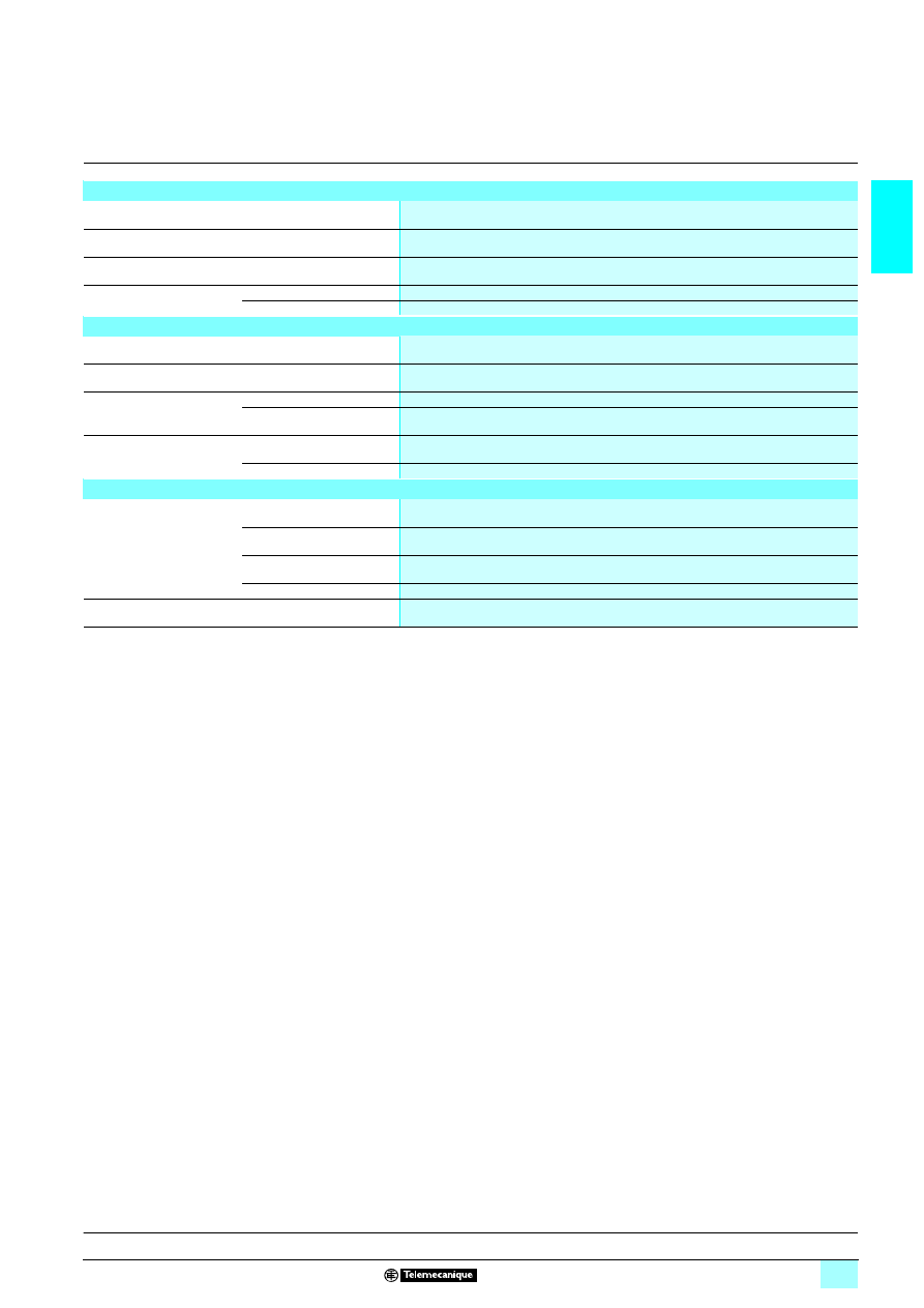
1/51
1
Characteristics
(continued)
1
Zelio Logic smart relays
1
Modem communication interface
Characteristics of “Com-Z” link with the smart relay
Type of connector
Specific to Zelio
Type of link
Specific Zelio communication protocol
Compatibility
Only with Zelio Logic smart relays SR
1 B11111 and SR2 E11111 version V3.1 and above
Isolation of
“Com-Z” connector
From the “Com-M” connector
By
6 1780 V opto-coupler
From the +/- supply terminals
By
6 1780 V opto-coupler
Characteristics of “Com-M” link with the Modem
Type of connector
Specific to Zelio
Type of link with
SR2 CBL07
RS 232 serial (included with the communication interface)
Compatibility
PSTN analogue modem
AT commands
GSM Modem
AT commands
Isolation of
“Com-M” connector
From the Modem
By the cable SR2 CBL07
From the +/- supply terminals
By the cable SR2 CBL07
Processing characteristics
Data saved by the interface
Messages
Up to 28 messages
Telephone/e-mail details
and recipient profiles
1 to 10 recipients (telephone numbers and/or e-mail addresses) per message
Date and time
Dating of messages to be sent
Discrete and digital values
Backup of values when the message activation condition is triggered.
Backup of data to be sent
Flash memory
Presentation, description :
pages 1/46 and 1/47
Functions, setting-up:
pages 1/48 and 1/49
References:
page 1/52
Dimensions:
page 1/53
Connections:
pages 1/54 and 1/55
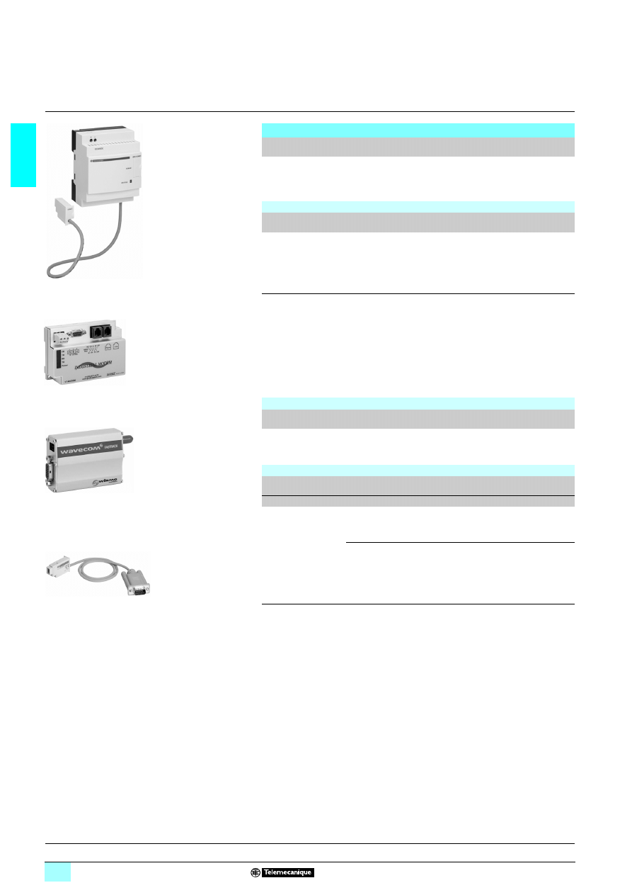
1/52
1
References
1
Zelio Logic smart relays
1
Modem communication interface
Modem communication interface
Description
For
use with
Supply
Reference
Weight
kg
Modem
communication
interface
(including cable
SR2 CBL07)
SR
2222 B22222
22222
22222
22222
SR2 E
22222
22222
22222
22222
8 12…24 V
SR2 COM01
(1)
0.200
Modems
Description
Supply
voltage
Reference
Weight
kg
Analogue PSTN Modem
Type SIXNET VT-MODEM-5-WW,
including a telephone cable
(length 2 m)
8 12…24 V
SR2 MOD01
0.265
GSM Modem
Type WAVECOM FASTRACK M1306 B
dual band 900/1800 Mhz,
including:
2 a supply cable
(length 1.5 m),
2 fixing lugs for plate mounting,
2 a SUB-D 9/SUB-D 15 cable
(length 0.5 m),
2 an antenna with cable
(length 2 m).
8 12…24 V
SR2 MOD02
(2)
0.445
Software
Description
Application
Compatibility
Medium
Reference
Weight
kg
Zelio Logic Alarm
PC
Windows 98,
NT4, 2000 and XP
CD-ROM
SR2 SFT02
0.200
Connection accessories
Description
Composition/
Application
Length
Reference
Weight
m
kg
Connection cables
SUB-D9/SUB-D9
connectors
Between modem
and PC
1.8
SR1 CBL03
0.110
Specific
Zelio/SUB-D9
connector
Between
communication
interface and
modem
0.5
SR2 CBL07
(3)
0.050
(1) Can only be used with "Zelio Soft 2" software version
2 3.1.
(2) Not recommended for North America or Japan
(3) Spare part (cable included with communication interface SR2 COM01).
SR2 COM01
52
30
83
SR2 MOD01
53
55
22
SR2 MOD02
53
55
23
SR2 CBL07
52
30
86
Presentation, description :
pages 1/46 and 1/47
Functions, setting-up:
pages 1/48 and 1/49
Characteristics:
pages 1/50 and 1/51
Dimensions:
page 1/53
Connections:
pages 1/54 and 1/55
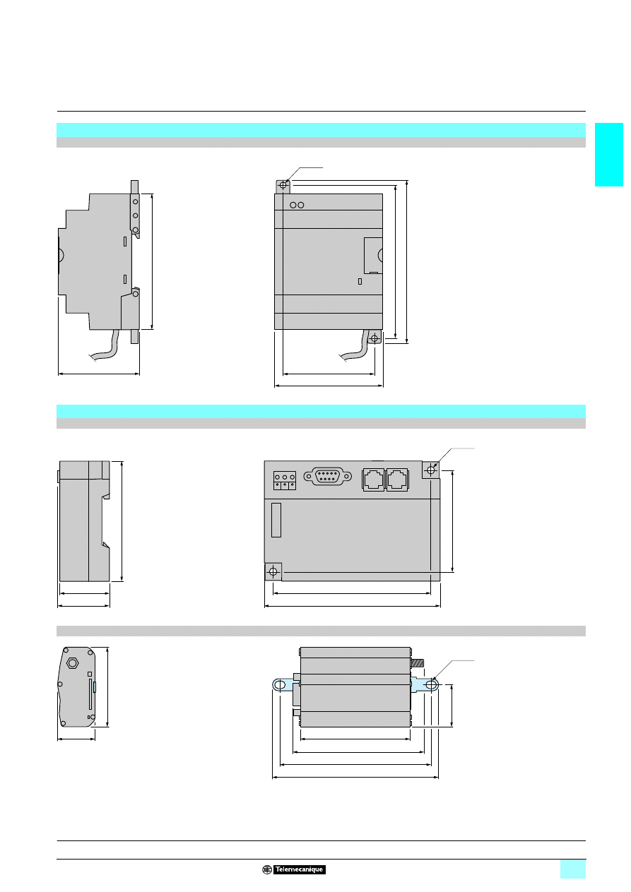
1/53
1
Dimensions
1
Zelio Logic smart relays
1
Modem communication interface
Communication interface
SR2 COM01
Modems
SR2 MOD01 (Analogue PSTN modem)
SR2 MOD02 (GSM modem)
60
72
59,5
90
100
107,6
2 x Ø4
118
106
70
2 x Ø4
31
33
80,5
73
88
101,2
111
25,5
54,5
27
Ø5 x 7
Presentation, description :
pages 1/46 and 1/47
Functions, setting-up:
pages 1/48 and 1/49
Characteristics:
pages 1/50 and 1/51
References:
page 1/52
Connections:
pages 1/54 and 1/55
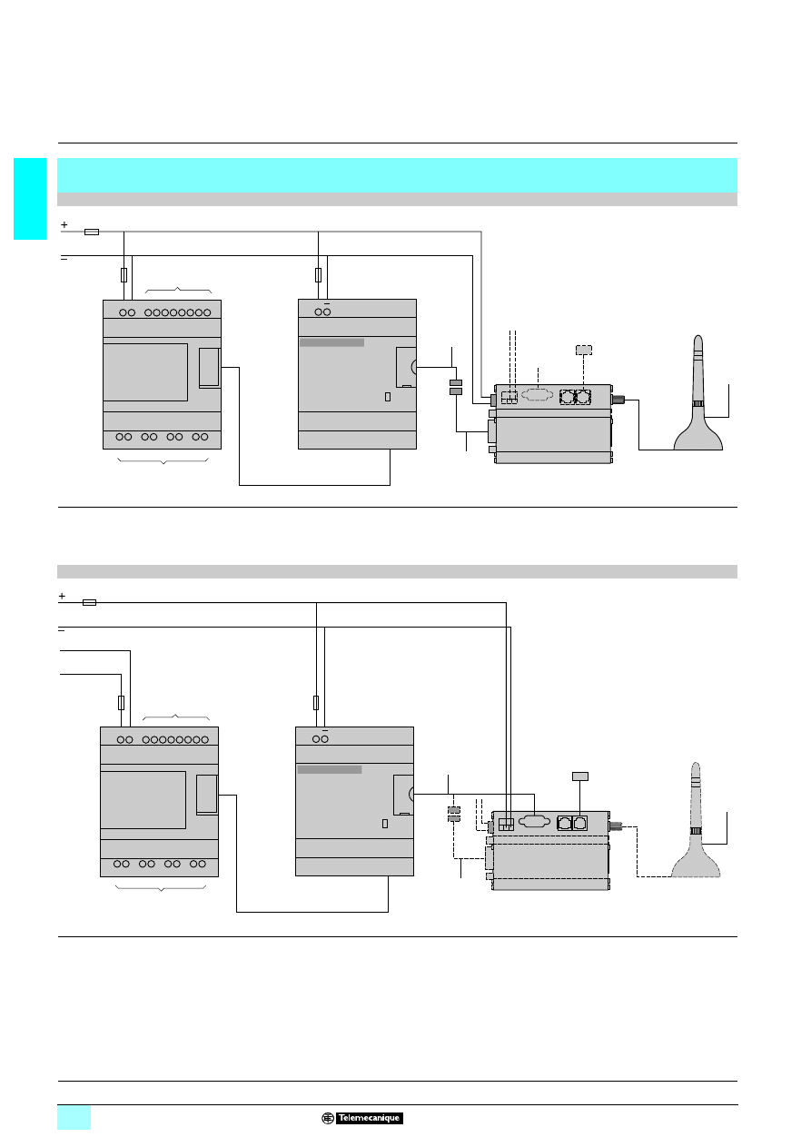
1/54
1
Connections
1
Zelio Logic smart relays
1
Modem communication interface
Connection schemes for connecting communication interface SR2 COM01 to the smart relay and the
Modem
SR
2222 B22
22
22
221JD, SR2222 B222
222
222
222BD and SR2 E222
222
222
222BD
(1) 1 A quick-blow fuse.
(2) Cable included with Modem communication interface SR2 COM01.
(3) Cable for connection to the Transmission network (included with analogue PSTN modem).
(4) Antenna and cable included with GSM Modem.
SR
2222 B22
22
22
221B, SR2222 B222
222
222
222FU, SR2 E222
222
222
222B and SR2 E222
222
222
222FU
(1) 1 A quick-blow fuse.
(2) Cable included with Modem communication interface SR2 COM01.
(3) Cable for connection to the Transmission network (included with analogue PSTN modem).
(4) Antenna and cable included with GSM Modem.
(1)
(2)
(4)
(4)
+
12-24VDC
SR2 COM01
COM-M
COM-Z
STATUS
+
I1 I2 I3 I4 I5 I6 IB IC
Q1
Q2
Q3
Q4
(3)
COM-M
–
+
(1)
1 12 or 24 V
Input
connections
Output
connections
GSM or Analogue
PSTN Modem
SR2 MOD01
or
SR2 MOD02
(1)
(3)
(2)
(4)
+
12-24VDC
SR2 COM01
COM-M
COM-Z
STATUS
+
I1 I2 I3 I4 I5 I6 IB IC
Q1
Q2
Q3
Q4
–
+
(4)
(1)
1 12...24 V
Input
connections
Output
connections
Analogue PSTN or
GSM modem
2 24 V or
2 100…240 V
SR2 MOD01
or
SR2 MOD02
Presentation, description :
pages 1/46 and 1/47
Functions, setting-up:
pages 1/48 and 1/49
Characteristics:
page 1/50 and 1/51
References:
page 1/52
Dimensions:
page 1/53
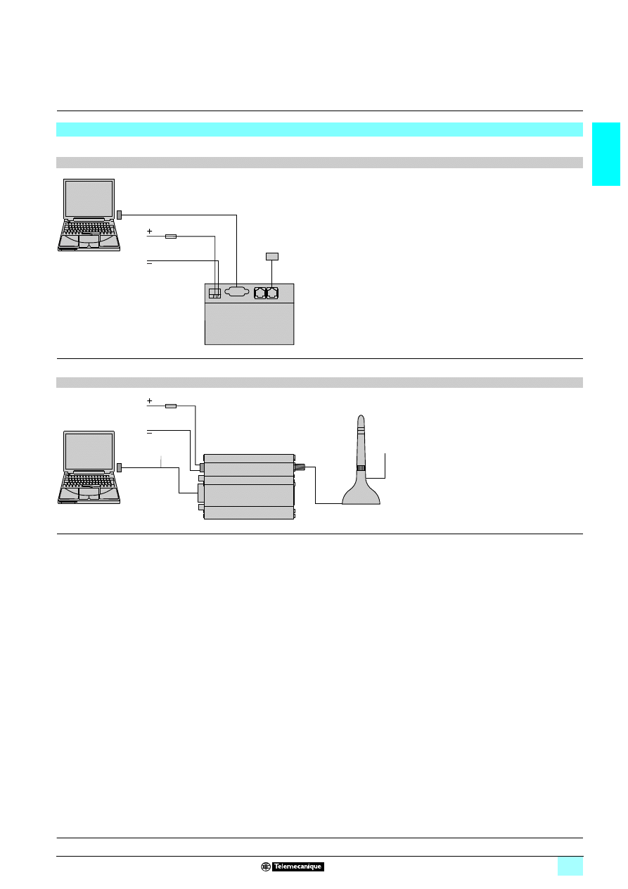
1/55
1
Connections
(continued)
1
Zelio Logic smart relays
1
Modem communication interface
Connection schemes for connecting the PC to the Modem
For PCs without an internal Modem.
Analogue PSTN Modem
(1) Cable for connection to the Transmission network (included with analogue PSTN modem).
(2) To be ordered separately.
GSM Modem
(1) Cable included with the Modem (length: 50 cm). The cable length can be increased using SR1 CBL03 (1.8 m).
(2) Antenna and cable included with GSM Modem.
(1)
SR1 CBL03
(2)
1 12...24 V
Zelio
Logic
Alarm
Analogue PSTN
Modem
(1)
(2)
1 12...24 V
GSM Modem
Antenna
Zelio
Logic
Alarm
Presentation, description :
pages 1/46 and 1/47
Functions, setting-up:
pages 1/48 and 1/49
Characteristics:
page 1/50 and 1/51
References:
page 1/52
Dimensions:
page 1/53
Wyszukiwarka
Podobne podstrony:
Elektroforeza DNA komórkowego BioAut1, BioAut2 i Ch1
ch1-pobieranie probek, weterynaria, Analityka, Próbówki
WYKLAD z fizyki atomowej i mol w3-4 2008, Fizyka, 13.Fizyka jądrowa, mat ch1
ch1
Ch1 Q1
Cw ch1, Akademia Morska Szczecin Nawigacja, uczelnia, Tomek, FIZYKA- SPRAWOZDANIA, FIZYKA- SPRAWOZDA
ch1 010902
Ch1 FundamentalOfPowerPlant 1 17 1 24
KIMMEL genderedsociety ch1
Ch0 Ch1 RationaleForForestEnergyProduction
CH1
ch1 revised id 110456 Nieznany
przykladowe zadania z fizyki jadrowej, Fizyka, 13.Fizyka jądrowa, mat ch1
cisco2 ch1 focus VRLS2G3H5FTBZYQ74NPB5LY5G4YM4HEVHUCF6TY
Ch1 Q3
Chromatografia cieczowa-CH1-CH2(1), NAUKA, chemia, lab
cisco2 ch1 concept T4CVTHOOK2UP7DYCEZ3YSGBWW62BKATM2APLUMY
cisco2 ch1 vocab HKRKBHHHSRQGUVIAIJ5YHAFAYK6FWYQNS7A2ILA
CH1 (3)
więcej podobnych podstron