
MDV-D Installation
Installation
1 Summarize of Installation …………………………………. …………....240
2 Installation of Outdoor unit ………………………………………..…... .242
3 Installation of Indoor unit …………………………………. …………….243
4 Installation of Refrigerant Pipe ………………………..…. …………….244
4.1 The permitted length and drop difference of refrigerant pipe………...244
4.2 Pipe size selection………………………………………………………....246
4.3 Precautions…………………………………………………………… .…249
4.4Dimension of Refrigerant Distributor………………….………………..251
4.5 Installation work of Refrigerant pipe……………………………...……252
4.6 Additional Charge of Refrigerant……………………………………….262
5 Processing & Installation of Drainage Pipe………………………….…..263
6 Installation Work…………..………...………..…………………………...266
7 Pipeline Installation…………..……………………………………………268
8 Electric Installation…………..………………….….….…………………..272
239
MDV-D Installation
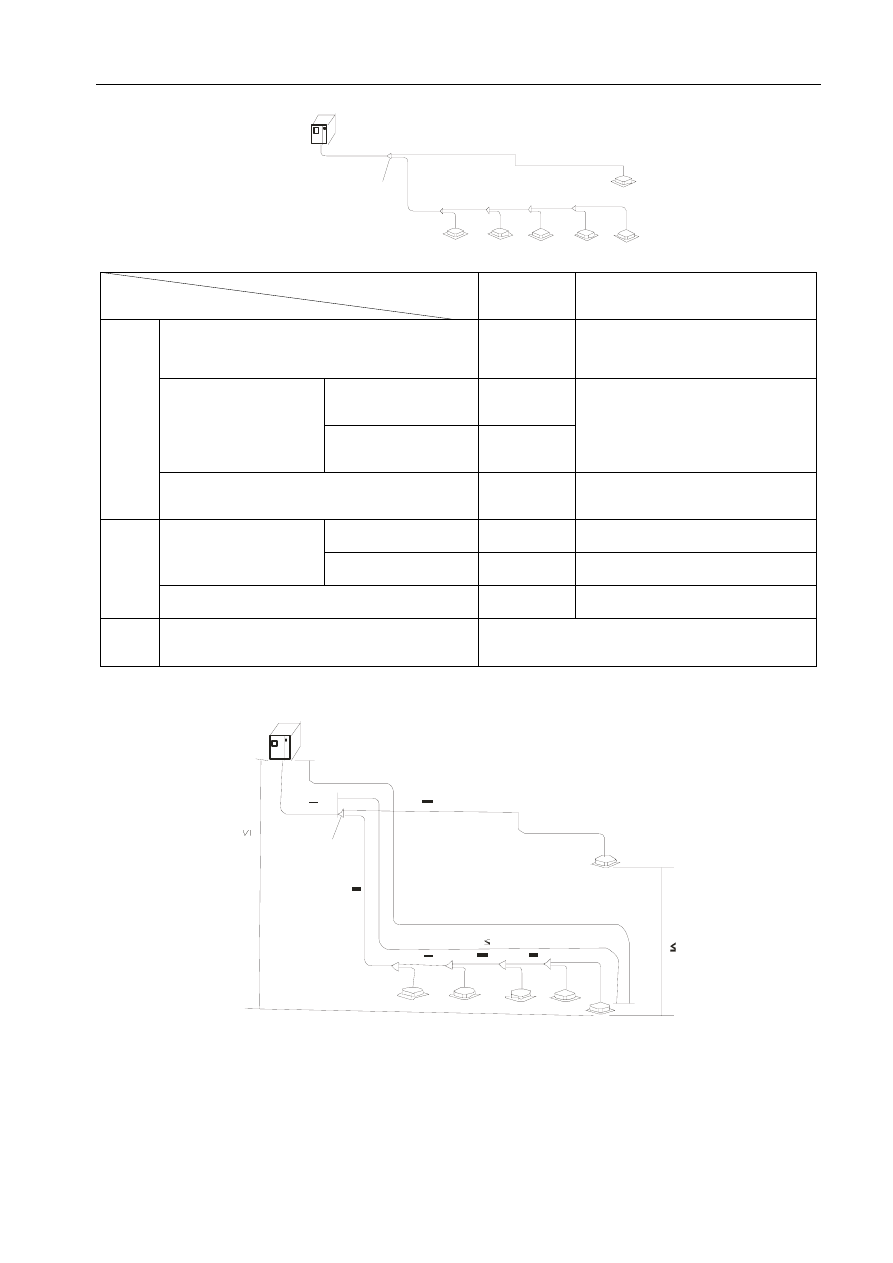
1 Summarize of Installation
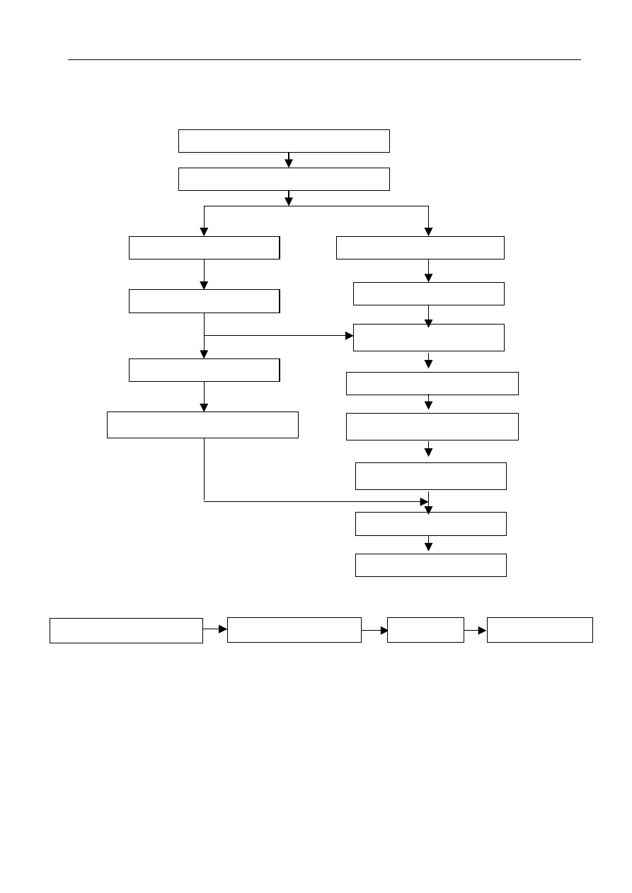
1.1 Installation Procedure
Confirm project, Sign contract
Audit shop drawing
Check and accept
Test run and debugging
Install decorative panel
Additional charge of refrigerant
Vacuum dry for refrigerant pipe
Pipeline making and installation
Pressure test
Install drainage pipe
Install outdoor unit
Install refrigerant pipe
Make foundation of outdoor unit
Install indoor unit
1.2 Install indoor units
Procedure:
Install hook
Install indoor unit
Label installation position
Confirm installation position
Note 1.The hook must strong enough to sustain the weight of indoor unit.
2.Check the models of indoor units before installation.
3.Pay attention to the main devices, such as the pipeline.
4.Obligate enough place for maintenance.
5.Obligate check point (400x400).
240
MDV-D Installation
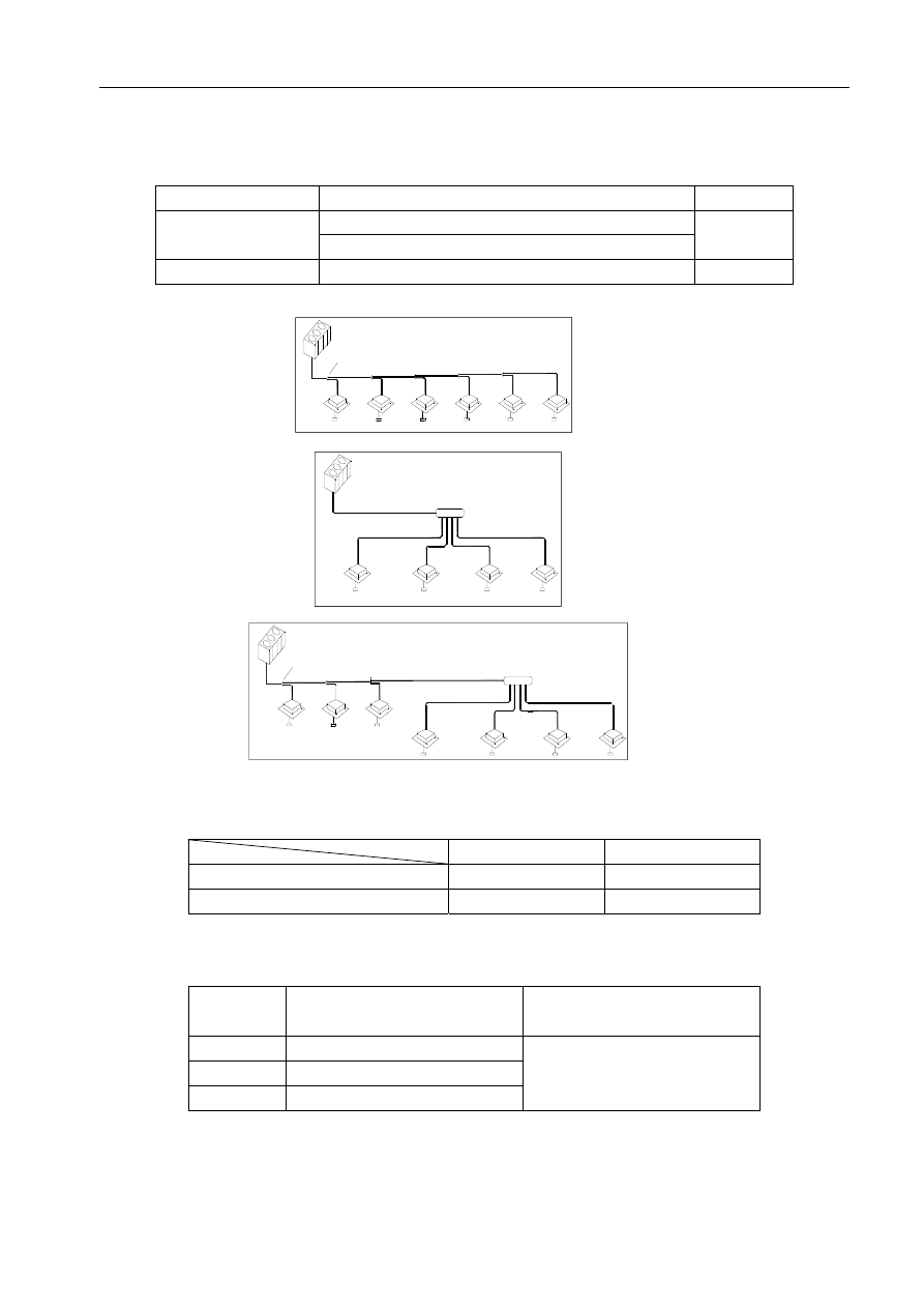
1.3 Refrigerant pipe
Procedure:
Vacuum dry
Pressure test
Blow
Temporary pipeline
Permute Nitrogen
Solder
Install pipe
Install indoor unit
1.4 Drainage pipe
Procedure:
Drain pipe heat-insulation
Check water leakage
Connect drain pipe
Install indoor unit
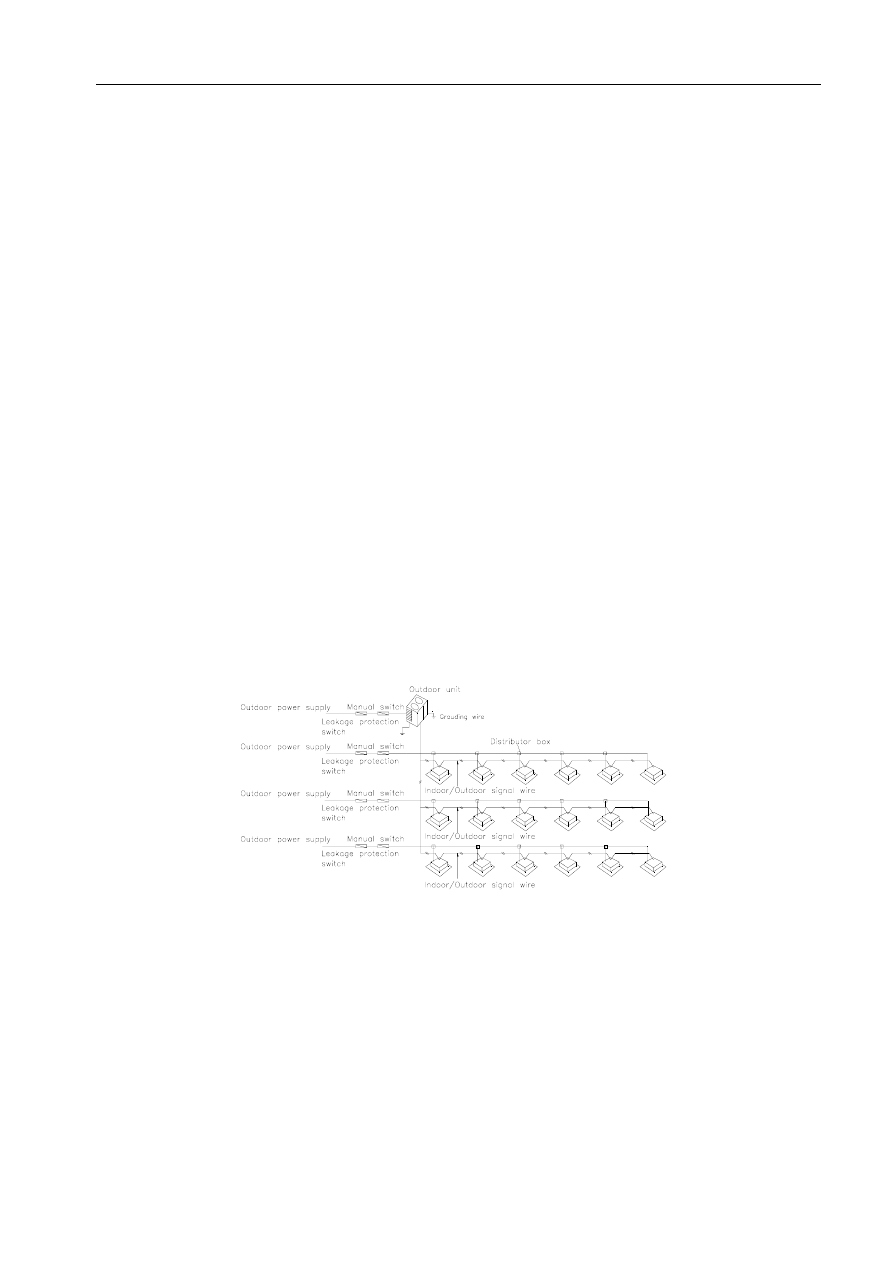
1.5 Electric wiring
1. Control wire: please pay attention to the consistency. When wiring parallel to the power wire, please
keep certain distance(300mm) to prevent interfering signal.
2. Power wire: please pay attention to select correctly the breaker switch, dimension of wire, and so on.
And both indoor units and outdoor units should be grounded well. The power wire and signal wire can’t
be enlaced together.
1.6 Lay the indoor pipeline
Note: Collocate the air-outlet reasonably to prevent airflow short-circuit. Check the static pressure is in the
allowable range. The air filters are easily to unpick and wash. Do pressure test on pipeline.
1.7 Heat-insulation
Procedure:
Heat-insulation work
Pressure test
Test the heat-insulated part
Refrigerant pipe work
Note: For welding part, flare part and branch pip, heat-insulation work must be done after finishing pressure test.
1.8 Install outdoor unit
Procedure:
Install outdoor unit
Heat-insulation work
Note: 1. Gutter must be set around the foundation to drain out the accumulated water.
2. When installing outdoor units at the housetop, please check the strength of the housetop and pay
attention not to destroy the waterproof of the housetop.
241

MDV-D Installation
1.9 Recharge refrigerant
Procedure:
Recharge refrigerant
Calculate the added volume according to liquid pipe length
Note: the calculation results must be correct.
1.10 Main points of test running and debugging
Examine the following before turning on the power: Vacuum dry, power wiring, control wiring, additional
charge of refrigerant, open the close-valve of gas pipe, open the close-valve of liquid pipe, test insulation.
Measure the indoor temperature in cooling mode and heating mode. Measure air-inlet temperature and discharge
temperature.
Measure the following for outdoor unit: insulation resistance, voltage, current, discharge pressure, air-inlet
pressure, discharge pipe temperature, air-inlet pipe temperature, compressor frequency.
2 Installation of Outdoor unit
2.1 Hanging and Transportation
(1) Sling the outdoor unit and carry it in with 4 steel wire (φ6mm or more)
(2) Use soft board to protect the unit surface from scratch and distortion where contact the steel wire.
20
Steel wire
Protect board
Base board
2.2 Required Installation Place and Installation Dimension
Please refer to the Outdoor Units.
242
MDV-D Installation
3 Installation of Indoor unit
2.1 Hanging and Transportation
Please refer to Indoor unit Installation Manual.
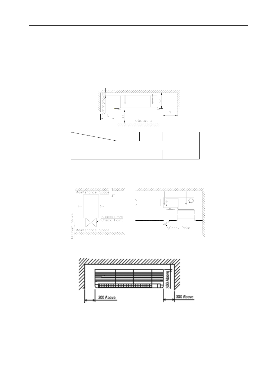
2.2 Required Installation Place
(1) Cassette Type
A B
C
One-way Cassette
1000mm
above
Four-way Cassette
1000mm above
2300mm above
(2) Duct Type
(3) Wall Mounted Type
243
MDV-D Installation
4 Installation of Refrigerant Pipe
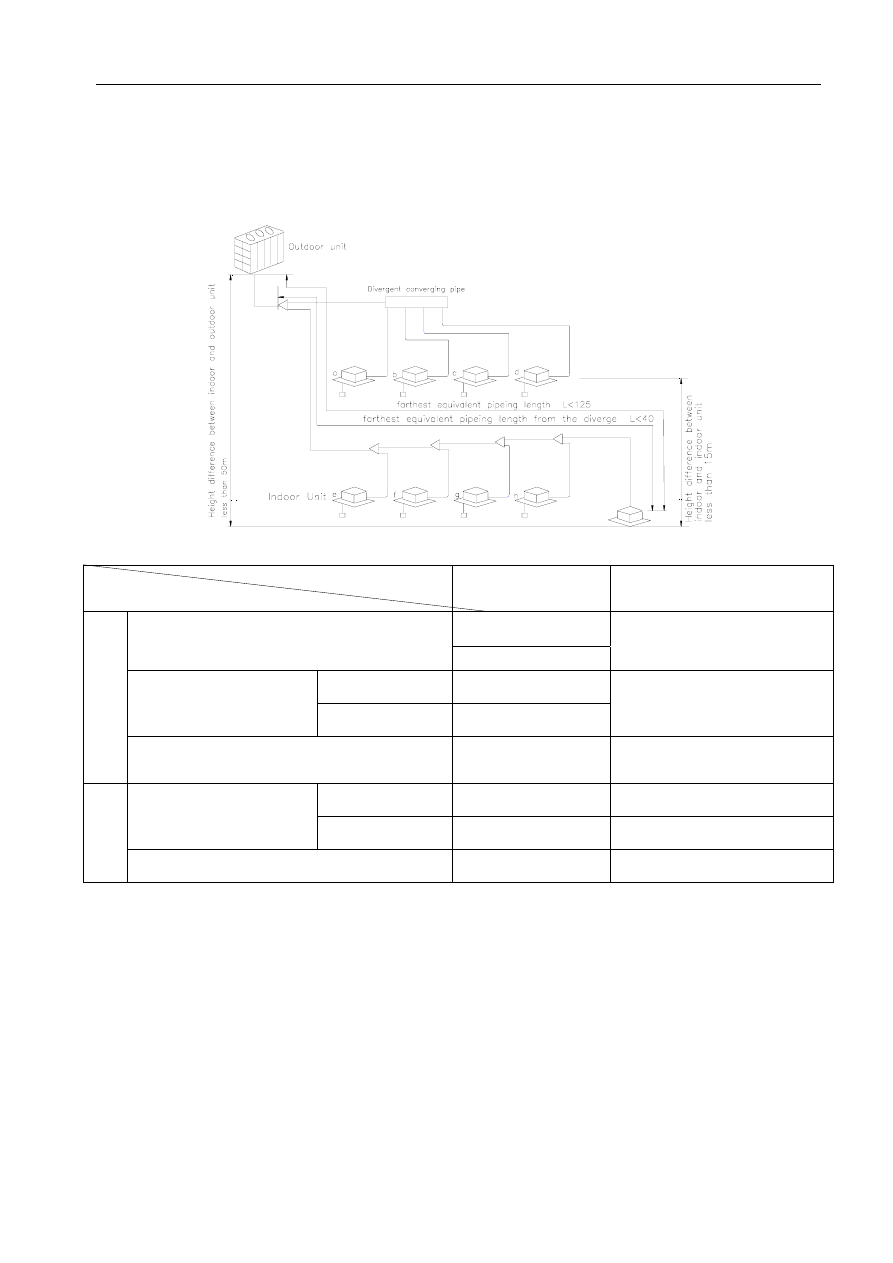
4.1 The permitted length and drop difference of refrigerant pipe
10~30HP
L2
L1
L4
L5
L6
i
Permitted length
Pipe
≤250m(less than 54kW)
Pipe total length (actual length)
≤300m(above 54kW)
L
1
+L
2
+L
3
+L
4
+L
5
+L
6
+L
7
+a+b+…i
Actual length
≤100m
Farthest pipe length m
Equivalent length
≤125m
L
1
+L
3
+L
4
+L
5
+L
6
+i
Pipe
length
Equivalent length L of pipe from the first branch
to the farthest one
m
≤40m
L
3
+L
4
+L
5
+L
6
+i
Above outdoor unit
≤50m ——
Drop height between indoor
unit and outdoor unit
Below outdoor unit
≤30m
——
Drop
height
Drop height between indoor unit and indoor unit
≤15m
——
Conversion of the equivalent length: Convert into the direct pipe length
according to branch Junction 0.5m/l and branch header pipe 1.0m/l.
244
MDV-D Installation
4~6HP
Outdo or Unit
The fir st l ine b ran ch pi pe
1
2
2
2
2
3
3
3
3
3
3
Permitted
length
Pipe
Pipe total length(actual length)
≤100m
L
1
+L
2
+L
3
+L
4
+L
5
+L
6
+L
7
+a+b+
c+d+e
Actual length
60m(140W)or
45m (1100W)
Farthest pipe length(m)
Equivalent length
70m(140W)or
50m (100W)
L
1
+L
3
+L
4
+L
5
+L
6
+e
Pipe
length
Equivalent length L of pipe from the first branch
to the farthest one(m)
≤20m L
3
+L
4
+L
5
+L
6
+e
Above outdoor unit
≤20m ——
Drop height between
indoor and outdoor unit
Below outdoor unit
≤20m ——
Drop
length
Drop height between indoor unit and indoor unit
≤8m ——
Pipe
O.D
Main pipe D1= 19.0 D3= 9.5 Branch
pipe D2= 15.9 D4= 9.5
Conversion of the equivalent length: Convert into the direct pipe length according to branch Junction 0.5m/l
and branch header pipe 1.0m/l.
H 8m
1
2
3
4
5
6
F
G
H
I
J
Outdoor Unit (one or more ou tdoor un its)
The first Line Branch Pipe
I nd oor U nit
Indo or Un it
In
do
or
U
ni
t t
o
In
do
or
U
n
it
Dr
op
He
ig
ht
Ma ximu m Piping Equi valen t Leng th L
(Fr om the f ir st Line branch pipe) Maximum pi ping
Equivalent Length L 20m
D
rop
H
eig
ht
be
tw
ee
n
Indo
or
uni
t a
nd ou
td
oor U
nit
H
50
m
e c
245
MDV-D Installation
4.2 Pipe size selection
4.2.1 The selection of the refrigerant pipe
Type of the pipe
Connecting part
No.
Between outdoor unit and the first branch part
Main pipe
Between the branch part and branch part
1 2
Branch pipe
Between the branch part and indoor unit
3
Branch Joint
Controller
Indoor Unit
1
3
2
2
3
3
3
1
Outdoor Unit
1
2
3
2
3
3
2
3
3
3
3
Invergent Branch
3
3
2
3
3
2
3
2
3
Outdoor Unit
Outdoor Unit
Indoor Unit
Indoor Unit
Controller
Controller
Indoor Unit
Branch Joint
4.2.2 Dimensions of the main and branch pipes
4~6 HP
gas side
liquid side
Dimensions of the main pipe
Φ19.0
Φ9.5
Dimensions of the Branch pipe
Φ19.0
Φ9.5
10~30 HP
A (hr)
Dimensions of the main pipe
(gas/liquid side)
Dimensions of the Branch pipe
(gas/liquid side)
A≤ 10
Φ28.6/Φ12.7
10<A≤ 20
Φ38.0/Φ19.0
20<A≤ 30
Φ45.0/Φ22.0
Φ19.0/Φ9.5
Notes: A means the horsepower sum of the all indoor units which are below the main pipe
.
246
MDV-D Installation
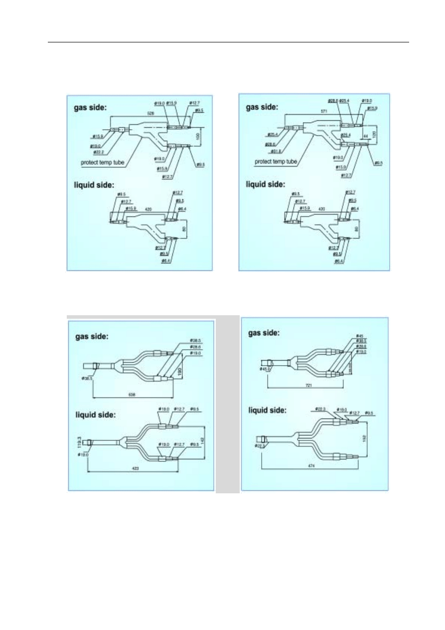
Indoor and outdoor unit pipes dimensions
Model MDV-
D22 ~ D140
D100(140)W/S(N2)
D280W/S(N2) D560W/S(N2) D840W/S(N2)
Gas
Φ19.0
Φ19.0
Φ28.6
Φ38.0
Φ45.0
Liquid
Φ9.5
Φ9.5
Φ12.7
Φ19.0
Φ22.0
Notes:
1. The main pipe dimension is consistent with that of the outdoor unit;
2. The branch pipe dimension is consistent with that of the indoor units.
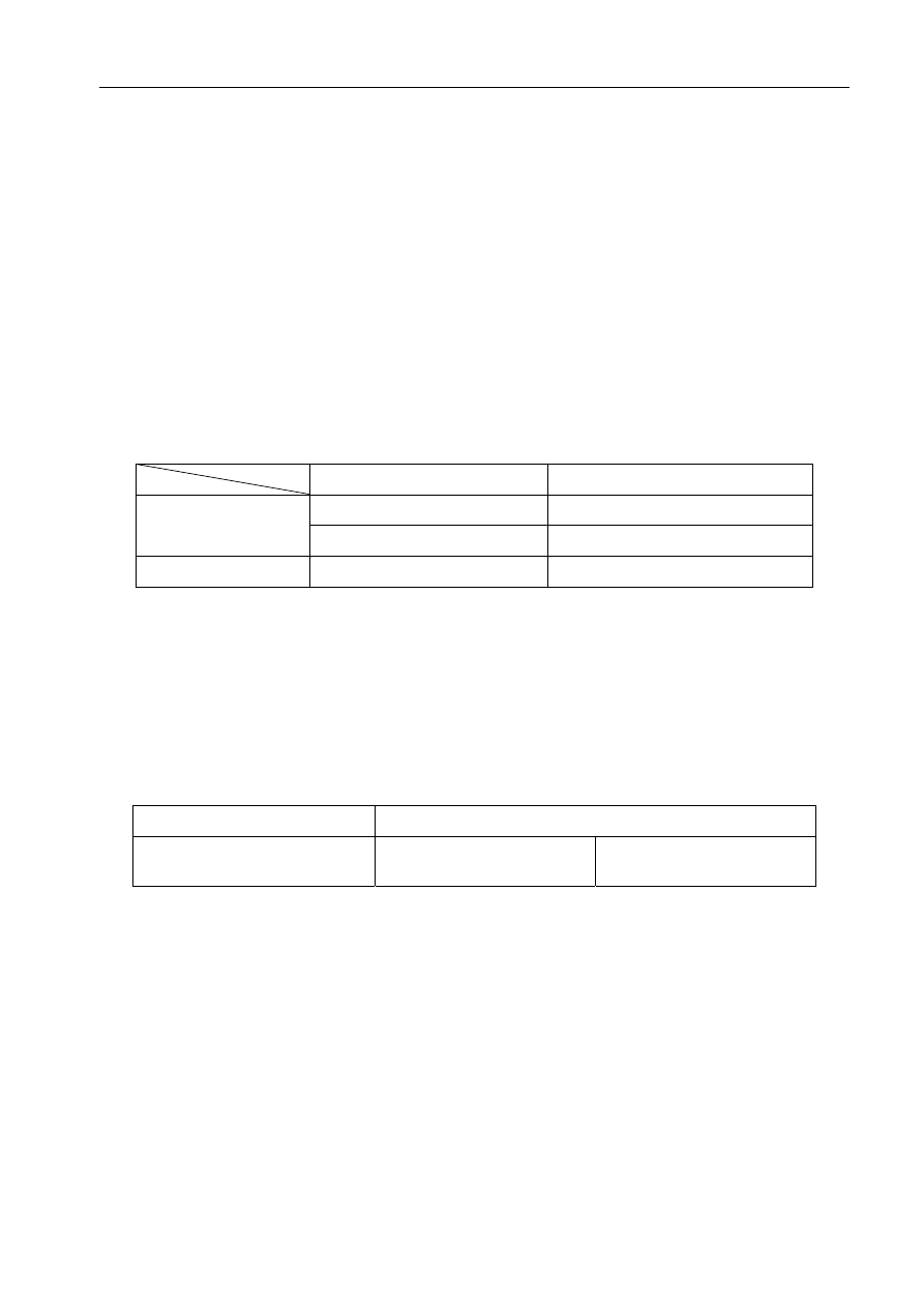
4.2.3 Selecting Branch Type
4~6HP
Model
Branch joint
(2-branch junction)
MDV-BY51 or MDV-BY101
10~30HP
Dimensions of the main pipe
(gas/liquid side)
Branch part
Φ28.6/Φ12.7
MDV-BY101
Φ38.0/Φ19.0
MDV-BY102
Φ45.0/Φ22.0
MDV-BY103
4.2.4 Connecting method
4~6HP
Gas side
Liquid side
Outdoor unit
Flaring nut
Flaring nut
Indoor unit
Flaring nut
Flaring nut
Branch part
Welding
Welding
BS device
Flaring nut
Flaring nut
10~30HP
Gas side
Liquid side
10HP Outdoor unit
Welding
Flaring nut
20HP Outdoor unit
Welding
Flaring nut
30HP Outdoor unit
Welding
Welding
Indoor unit
Flaring nut
Flaring nut
Branch part
Welding
Welding
247
MDV-D Installation
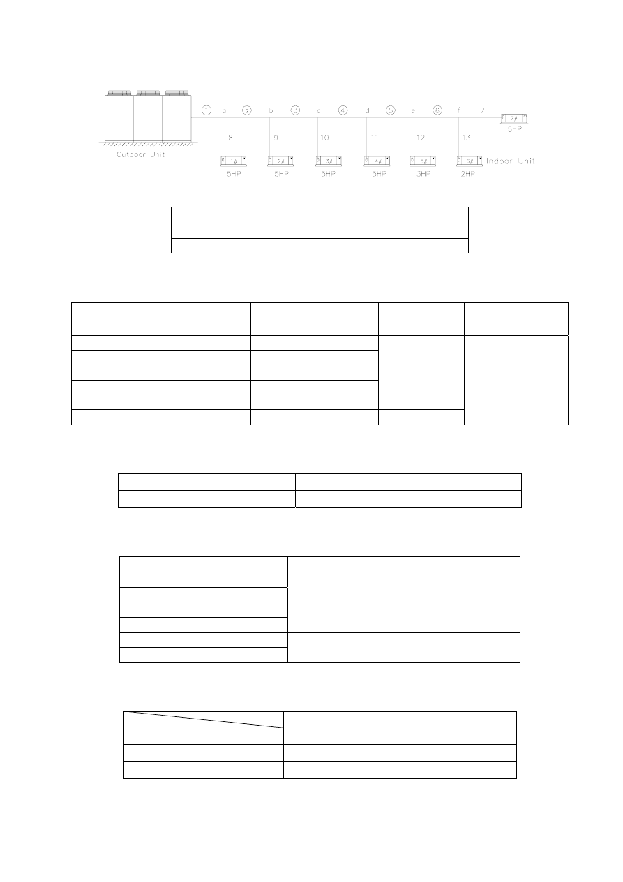
4.2.5 Example as 10~30HP
Selecting the refrigerant pipe
Type of pipe
No.
Main pipe
or —
Branch pipe
7—13
Selecting the dimension of main pipe
No.
Indoor units below
main pipe
Total HP of indoor units
below main pipe
A (hr)
Pipe dimension
(Gas/Liquid)
main pipe 1#—7# 5×5+3+2=30
(HP)
main pipe 2#—7# 4×5+3+2=25
(HP)
20<A≤ 30
Φ45.0/Φ22.0
main pipe 3#—7# 3×5+3+2=20
(HP)
main pipe 4#—7# 2×5+3+2=15
(HP)
10<A≤ 20
Φ38.0/Φ19.0
main pipe 5#—7# 5+3+2=10
(HP)
A≤ 10
main pipe 6#—7# 5+2=7
(HP)
A≤ 10
Φ28.6/Φ12.7
Selecting the dimension of branch pipe
Branch pipe
Pipe dimension (Gas/Liquid)
7—13
Φ19.0/Φ9.5
Selecting branch joint
Branch part
Model
a
b
MDV-BY103
c
d
MDV-BY102
e
f
MDV-BY101
Selecting connection method
Gas side
Liquid side
30HP Outdoor unit
Welding
Welding
Indoor unit
Flaring nut
Flaring nut
Branch part( a—f )
Welding
Welding
248
MDV-D Installation
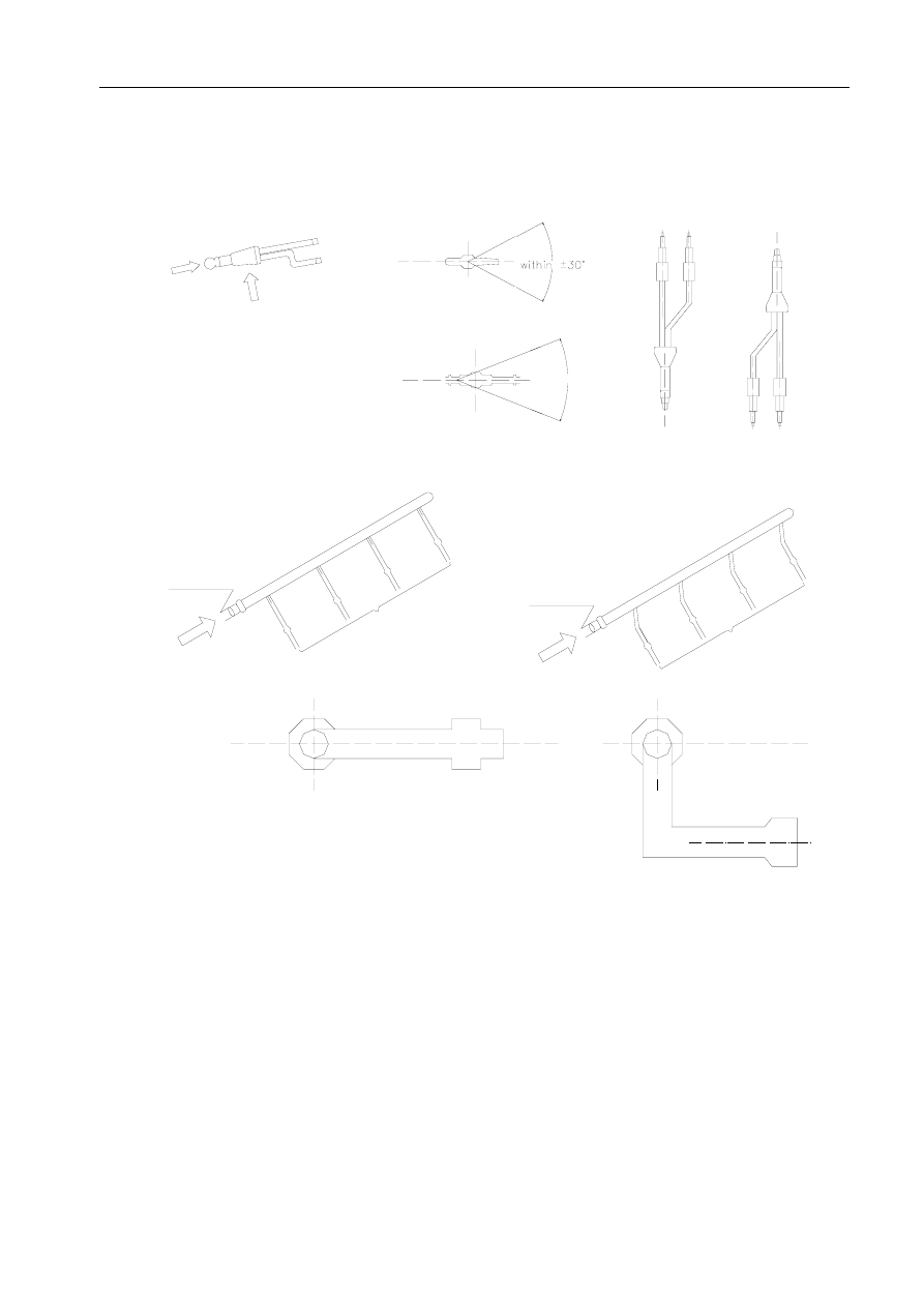
4.3 Precautions:
4.3.1 Refrigerant pipe must use the pipe with specified diameter.
4.3.2 Branch Junction could be installed in horizontal mode or vertical mode.
B
OR
A
HORIZONTAL
LINE
A direction
HORIZONTAL
LINE
B direction
within
30
4.3.3 Branch converging pipe must be installed in horizontal direction
B direction
Refrigerant Distributor
(gas side)
TO
IN
DO
OR
U
NI
T
B direction
TO
IN
TD
OO
R
UN
IT
Refrigerant Distributor
(liquid side)
HORIZONTAL LINE
B direction
B direction
4.3.4 Branch converging pipe is connected to the indoor unit and no more branch is allowed after one branch
converging pipe.
249
MDV-D Installation
250
indoor unit
controllor
outdoor unit
Branch Converging Pipe
wrong connection
wrong connection
wrong connection
4.3.5 Electric throttle kit must be installed vertically
To indoor unit
To outdoor unit
Electric expand valve
Electric throttle kit must
be placed vertically
4.3.6 Refrigerant fastness, the Refrigerant fastness, the distance between the support of the cross direction tube
(copper tube):
Nominal diameter
Below 16
16—25
Above 32
Max. distance (m)
1.0
1.5
2.0
4.3.7 Calculation of the pipe length
Available length of pipe =pipe length + the amounts of branch × branch equivalent length +the amounts
of elbow × elbow equivalent length.
Conversion of the branch equivalent length: convert into the direct pipe length according to branch
Junction 0.5m/l and branch header pipe 1.0m/l.
Conversion of elbow equivalent length.
Gas pipe dimension
Φ12.7
Φ15.9
Φ19.0
Φ25.4
Φ28.6
Junction(90°elbow)
0.10 0.10 0.15 0.15 0.20
MDV-D Installation
4.4 Dimension of refrigerant distributor
1) BY51 2) BY101
3) BY102 4) BY103
251
MDV-D Installation
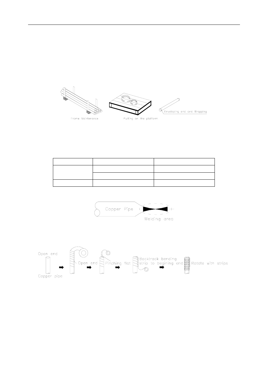
4.5 Installation work of Refrigerant pipe
4.5.1 Protection of Refrigerant pipe material
Transportation and storing of refrigerant pipe
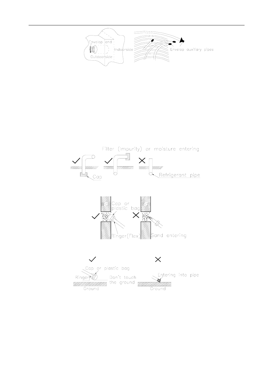
When transporting the pipes, please protect the pipes from wending and distortion. Please place a cap at
the open end of the pipe in order to prevent water and mud entering, and store in the appointed site.
All the open ends of the pipes need to be protected. The best feasible means is Enveloping End, and you can
select the easy means of Wrapping. Refer to the following table to select the means used in different sites.
Site Period
Maintenance
Means
Above three months
Envelop End
Outdoor
Below three months
Envelop End or Wrapping
Indoor
No limit
Envelop End or Wrapping
Envelop End: Welding the leak while clamping the end of the pipe.
Wrapping: Wrapping the pipe with polyethylene insulation tape.
The following operation should be noted:
When putting the pipe through the hole, filth can easily enter into the pipe.
252
MDV-D Installation
When the pipe is outside, rainwater can easily enter into the pip, especially when the pipe is
placed vertically.
Precautions:
Protect the open end of the pipe against moisture, dust and litter.
Before finishing pipe connection, place a cap at the open end of the pipe.
Try to make the open end of the pipe thwart or downward.
A cap must be placed on the end of the pipe when the pipe crosses the hole in the wall.
Don’t place the pipe on the ground directly or scratch with the ground.
Cut the pipe and remove burrs with the cut surface downward.
Be sure to place a cap when raining.
253
MDV-D Installation
4.5.2 Welding
Be sure to weld horizontally or downward, not upward.
Pay attention to the installation direction and angle to prevent oil-return or oil-accumulation..
It’s necessary to charge nitrogen when welding.
Be far away from fire and prepare fire extinguishers and water to prevent fire on field.
Be careful not to injure people.
Confirm the proper clearance between pipe and connector..
Check if the supporting structural members are strong enough.
The traverse distances between supporting structural members are as follows:
Diameter (mm)
Below 20
25~40
50
Max. Distance (m)
1.0
1.5
2.9
Min. inserting depth and clearance between connectors.
Unit: mm
Out .Diameter. (D)
Min. Inserting depth (B)
Clearance (A~D)
5 D 8 6
8 D 12 7
0.050~0.21
11 D 16 8
16 D 25 10
0.050~0.27
25 D 35 12
A
D
35 D 45 14
0.050~0.35
4.5.3 Flare Connection
Before flaring, the auxiliary pipe must be annealed.
Use incision machine.
254
MDV-D Installation
Dimension:
Shape Diameter O.D. A
3/8"
9.53
1/2" 12.7
0.05—0.21
5/8" 15.88
3/4" 19.05
0.05—0.27
Smear oil at flaring part.
Be careful to get rid of burr.
Use two torques.
Use proper torque to fasten nut.
Torque
Dimension
(kgf ·m)
(N·cm)
1/4"(Φ6.4) 144—176
1440—1720
3/8"(Φ9.5) 133—407
3270—3990
1/2"(Φ12.7) 504—616
4950—6030
5/8"(Φ15.9) 630—770
6180—7540
3/4"(Φ19.0) 990—1210
9270—11860
4.5.4 Laying
Laying the refrigerant pipes
Mark the system clearly in every distance to prevent wrong connection.
The plane where the two branches locate should be parallel to the horizontal plane, or the main pipe of the
branch pipe is vertical to the horizontal plane, which can avoid bad effect due to uneven distribution of gas and
liquid.
Protection of outdoor refrigerant pipes
Sudden damnification also should be considered except heat-insulated layer. If the length of bare part is over
1m, a buckle-board must be added to the bare part.
255
MDV-D Installation
Laying principle of MDV refrigerant pipes
Centralized laying, laying along the wall, and trying to make full of use of corridor.
After finishing laying, binding up the refrigerant pipes with white binding-strap. After finishing winding-up
every pipe separately, please try to binding up all pipes together according to the diameters and the degree of
tightness should be based on no feeling of flexible.
When installing the connection pipes and electric wires(power wire, control wire), they should be laid along
the wall, turn the corner logically, flat and straight, parallel with each other and packed together. And try to avoid
striding over and blocking the traffic.
The connection pipes and electric wires should be as short as possible.
Try to bind up all pipes and no bareness is allowed at the connecting part.
Precautions about laying refrigerant pipes
Pulling pipe: mark the system No. in the pipes to prevent wrong connection.
Make sure the support of the pipes is firm enough.
(5) Requirements of protection and appearance
4.5.5 Refrigerant pipe Flushing
Refrigerant pipe flushing is a method to eliminate filter. It has three main functions:
When nitrogen is insufficient, flushing can eliminate oxide air bubble.
When the end of the pipe can’t sealed well, flushing can eliminate filter and humidity.
Flushing can check the indoor/outdoor pipe connection.
Main procedure is as the following:
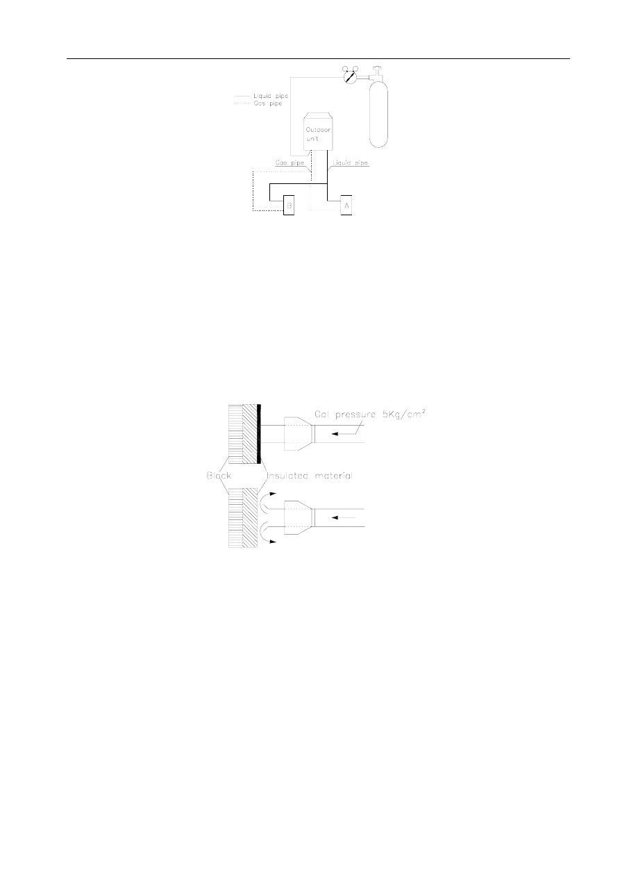
(1) Install pressure modulation valve at the nitrogen cylinder. And the gas used must be nitrogen. Carbon Dioxide
will probably condense. And Oxygen will probably cause explosion.
(2) Use charge pipe to connect pressure modulation valve and outdoor liquid pipe.
256
MDV-D Installation
(3) Jam well all the connection part in liquid side except indoor unit A.
(4) Open the valve of nitrogen cylinder to 5kgf/cm
2
.
(5) Check if there is nitrogen in liquid pipe of indoor unit A.
(6) Flushing
Use the insulating material in hand to resist the nozzle of gas main pipe of the indoor unit.
When the pressure can’t be resisted, release the insulating material quickly (flushing for the first time), then
use the insulating material to resist the nozzle again (flushing for the second time).
The dunghill can be checked by putting a piece of cloth in the nozzle loosely. Occasionally, some dampness
can be found, please dry the pipe thoroughly. Do as follows:
Scouring the inner part of the pipes with nitrogen until no dampness.
Do the vacuum drying procedure(see the MDV refrigerant pipes vacuum drying in detail)
(7) Close the nitrogen main valve.
(8) Repeat the above operations.
(9) After finishing flushing the liquid pipes, then flushing the gas pipes.
257
MDV-D Installation
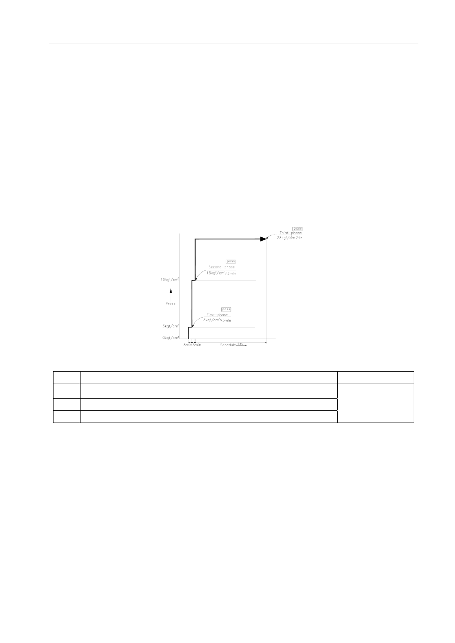
4.5.6 Refrigerant pipe Pressure Test
Adding pressure operation
During pressure test, the valves on gas side and liquid side should be full-closed.
Because nitrogen may enter into the outdoor circulation system, strengthening the valves before
adding pressure operation.
For every refrigerant system, add pressure slowly and orderly from gas and liquid side.
And the gas used must be nitrogen. Carbon Dioxide will probably condense. And Oxygen will
probably cause explosion.
The time must be over 24h in the third-phase of adding pressure.
Sketch map of adding pressure.
Control diagram for adding pressure by stages
No.
Phase (add pressure by stages)
Standard
1
Add pressure 3.0kgf/cm
2
G for more than 3 minutes to check big leakage.
2
Add pressure 15.0kgf/cm
2
G for more than 3 minutes to check big leakage.
3
Add pressure 28.0kgf/cm
2
G for more than 24 hours to check small leakage.
No pressure falling
Observe the pressure
Add pressure 28.0kgf/cm
2
G for more than 24 hours, pass if there’s no pressure falling. If the pressure falls,
it should be corrected. After that, if the pressure is still lower than that when adding pressure, the leakage should
be checked out and corrected.
Correcting method
If there’s 1 difference in temperature, there will be 0.1 kgf/cm
2
difference in pressure.
Correcting formula: actual value = pressure in the stage of adding pressure +(temperature in the stage of
258
MDV-D Installation
adding pressure – observed temperature ) x 0.1 kgf/cm
2
Compare the correcting value and adding pressure value to see whether the pressure falls.
Look up the leakage point in three phases when the pressure falls.
Check the leakage by ears---can hear loud noise of the leakage.
Check the leakage by hands---put the hands in the pipe connection to check the leakage.
Check the leakage by suds---the leakage point will emit air bubble.
Check the leakage by halogen detector.
Use halogen detector when finding the tiny leakage point or pressure falls but no leakage point can be
found during the adding pressure test.
Place the nitrogen under 3.0 kgf/cm
2
Add fluorin to the point 5.0 kgf/cm
2
(mixed state of fluorin and nitrogen).
Check by halogen detector, alkyl detector, electric detector and so on.
If no leakage can be found, continue to add pressure to 28.0 kgf/cm
2
, then check again.
Precautions
The maximum pressure in gas proof test should not exceed 28.0 kgf/cm
2
If the pipe is too long, check by sections.
Indoor side
Indoor side + Vertical pipe
Indoor side+ Vertical pipe +Outdoor side
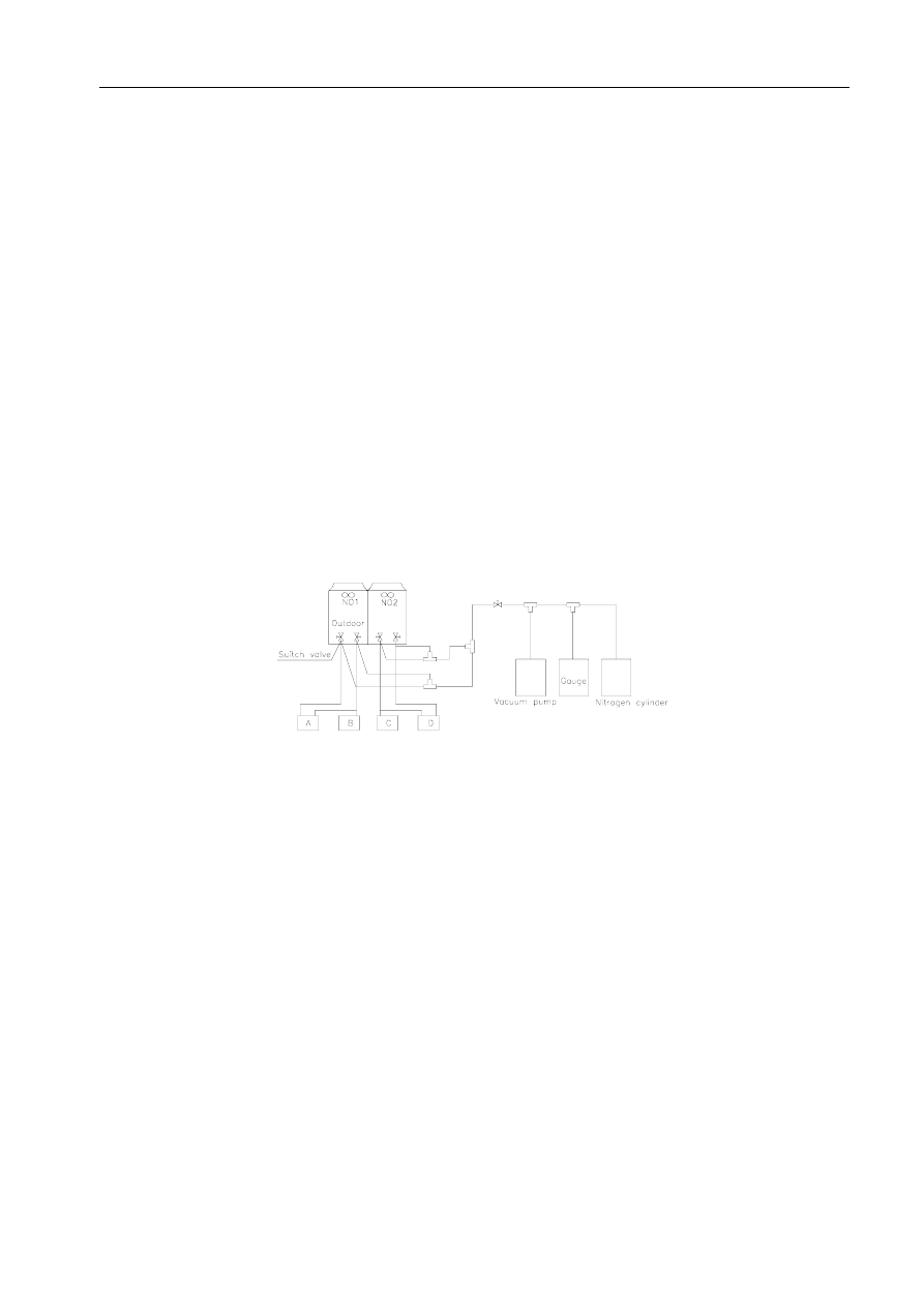
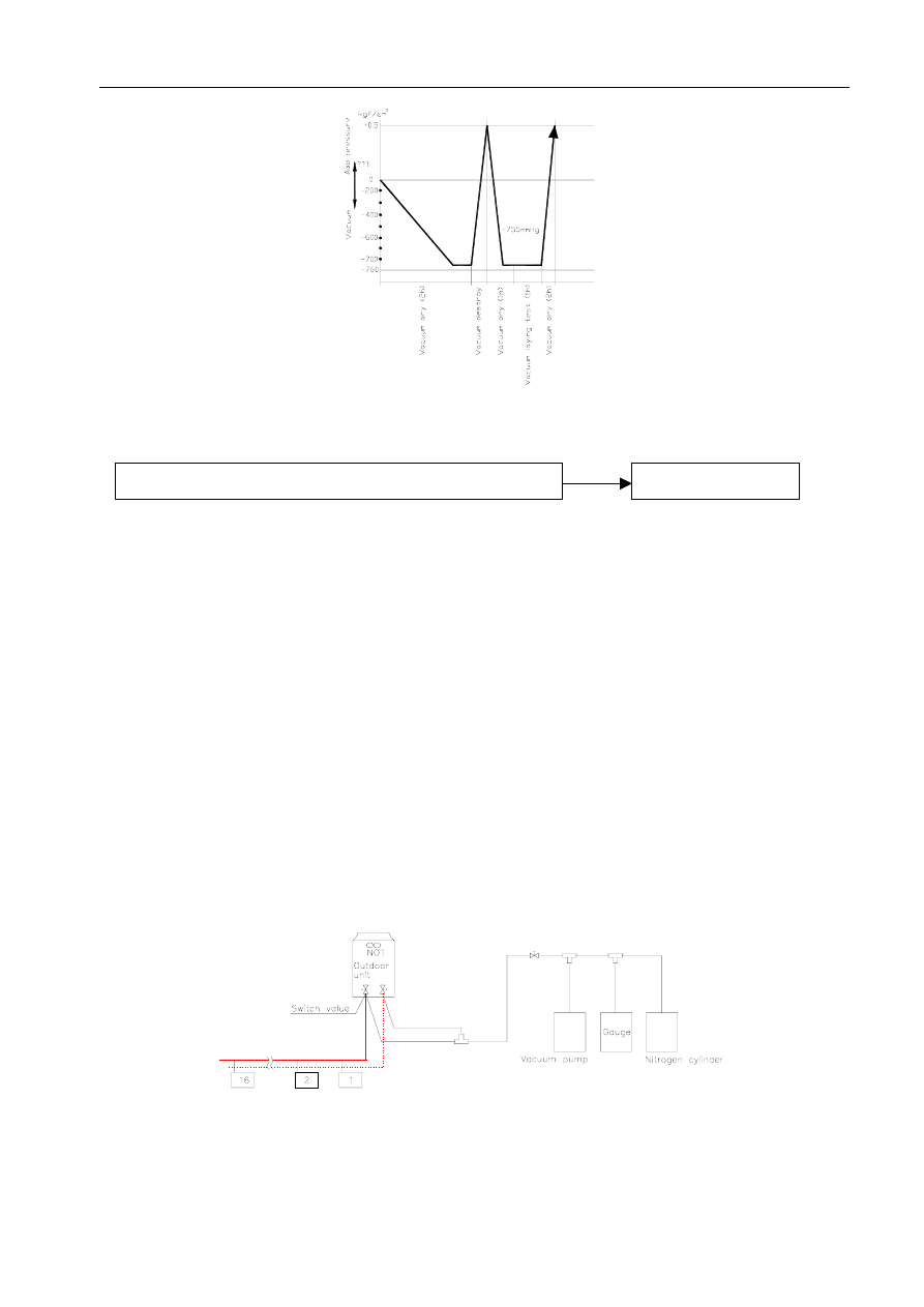
4.5.7 Vacuum Dry for Refrigerant pipe
Vacuum Dry: use vacuum pump to change the moisture (liquid) into steam (gas) in the pipe and discharge it
out of the pipe to make the pipe dry. Under one atmospheric pressure, the boiling point of water(steam
temperature) is 100 . Use vacuum pump to make the pressure in the pipe near vacuum state, the boiling point of
water falls relatively. When it falls under outdoor temperature, the moisture in the pipe will be vaporized.
259

MDV-D Installation
Selection of vacuum pump
Select the vacuum pump. (Normally the anticipative demand achieves -755mmHg)
Big discharge volume (over 40l/min). Check the vacuum calculator before operation to make
sure its measure range achieve below -755mmHg.
Boiling point of water( )
Gas pressure (mmHg)
Vacuum degree (mmHg)
40 55
-705
30 36
-724
26.7 25 -735
24.4 23 -737
22.2 20 -740
20.6 18 -742
17.8 15 -745
15.0 13 -747
11.7 10 -750
7.2 8
-752
0 5
-755
Vacuum dry procedure
There are two methods of vacuum dry due to different construction environment: common vacuum dry,
special vacuum dry.
Common vacuum dry procedure
Vacuum dry (for the first time)---connect the all-purpose detector to the inlet of liquid pipe
and gas pipe, and run the vacuum pump more than two hours (the vacuum pump should be
below -755mmHg)
260
MDV-D Installation
If the pump can’t achieve below -755mmHg after pumping 2 hours, moisture or leakage point
will still exist in the pipe. At this time, it should be pumped 1 hour more.
If the pump can’t achieve -755mmHg after pumping 3 hours, please check if there’s some
leakage points.
Vacuum placement test: place 1 hour when it achieves -755mmHg, pass if the vacuum watch
shows no rising. If it rises, it shows there’s moisture or leakage point.
Vacuuming from liquid pipe and gas pipe at the same time.
Sketch map of common vacuum dry procedure.
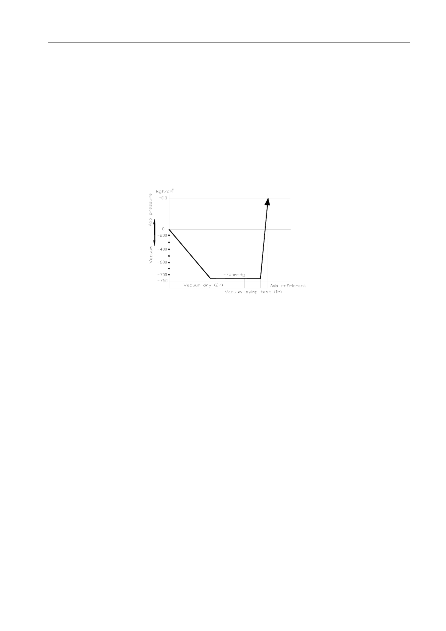
Special vacuum dry procedure
This vacuum dry method is used in the following conditions:
There’s moisture when flushing the refrigerant pipe.
Rainwater may enter into the pipe.
Vacuum dry for the first time ······ 2h pumping
Vacuum destroy for the second time ······ Fill nitrogen to 0.5Kgf/cm
2
Because nitrogen is for drying gas, it has vacuum drying effect during vacuum destroy. But if
the moisture is too much, this method can’t dry thoroughly. So, please pay more attention to
prevent water entering and forming condensation water.
Vacuum dry for the second time······1h pumping
Determinant: Pass if achieving below -755mmHg. If -755mmHg can’t be achieved in 2h, repeat
procedure
and .
Vacuum placing test ······ 1h
Sketch map of special vacuum dry procedure
261
MDV-D Installation
4.6 Additional Charge of Refrigerant
Procedure
Refill refrigerant
Calculate refrigerant volume according to liquid pipe length
The refrigerant needed by the pipes installed on fields is not filled in the factory. After finishing
installation, add refrigerant when the length of liquid pipe on field is over 0m.
Calculation
Refill volume (kg) = (L
1
×0.065 kgf/cm
2
) + (L
2
×0.115 kgf/cm
2
) +
(L
3
×0.290 kgf/cm
2
) + (L
4
×0.380 kgf/cm
2
)
In the above formula: L
1
—Φ9.5 Total real length of liquid pipe (m)
L
2
—Φ12.7 Total real length of liquid pipe (m)
L
3
—Φ19.0 Total real length of liquid pipe (m)
L
4
—Φ22.0 Total real length of liquid pipe (m)
Write the added volume in the outdoor nameplate.
The added volume must be measured with electron scale.
262
MDV-D Installation
5. Processing &Installation of Drainage Pipe
5.1 Gradient and Supporting
Keep the drainpipe sloping downwards at a gradient of at least 1/100. Keep the drainpipe as short as
possible and eliminate the air bubble.
The horizontal drainpipe should be short. When the pipe is too long, a prop stand must be installed to keep
the gradient of 1/100 and prevent bending. Refer to the following table for the specification of the prop
stand.
Diameter
Distance between the prop stands
Hard PVC pipe
25~40mm
1.5~2m
Precautions
The diameter of drainpipe should meet the drainage requirement at least.
the drainpipe should be heat-insulated to prevent atomization.
Drainpipe should be installed before installing indoor unit. After powering on, there is some water in
water-receiver plate. Please check if the drain pump can act correctly.
All connection should be firm.
Wipe color on PVC pipe to note connection.
Climbing, horizontal and bending conditions are prohibited.
The dimension of drainpipe can’t less than the connecting dimension of indoor drainpipe.
Heat-insulation should be done well to prevent condensation.
Indoor units with different drainage type can’t share one convergent drainpipe.
5.2 Drainpipe Trap
If the pressure at the connection of the drainpipe is negative, it needs to design drainpipe trap.
Every indoor unit needs one drainpipe trap.
A plug should be designed to do cleaning.
Plug
50
cm
50
cm
5.3 Upwards drainage(drain pump)
263
To ensure the gradient 1/100, the drainpipe can be lifted to 340mm. After upwards, place downwards, or it
MDV-D Installation
will cause malfunction to drain pump.
5.4 Convergent drainage
The number of indoor units should be as small as possible to prevent the traverse main pipe overlong.
Indoor unit with drain pump and indoor unit without drain pump should be in different drainage system.
Selecting the diameter
Number of connecting indoor units→Calculate drainage volume→Select the diameter
Calculate allowed volume =Total cooling capacity of indoor units(HP)×2 (l/ hr)
Allowed
volume(lean 1/100) (l/ hr)
I.D. (mm)
Thick
Hard PVC
≤14
25
3.0
Hard PVC
14
≤88
30
3.5
Hard PVC
88
≤334
40
4.0
Hard PVC
175
≤334
50
4.5
Hard PVC
334
80
6.0
5.5 Drainage test
Drainage without drain pump
After finishing drainpipe installation, pour some water into the water receiver plate to check if the water
flows smoothly.
Drainage with drain pump
Poke the Water Level Switch , remove the cover, use water pipe to pour 2000ml water into the water
receipt plate through the water inlet.
264
MDV-D Installation
Turn on the power to Cooling operation. Check the pump’s operation and switch on the Water Level
Switch. Check the pump’s sound and look into the transparent hard pipe in the outlet at the same time
to check if the water can discharge normally.
Stop the air conditioner running, turn off the power, and put back the cover.
Stop the air conditioner. After 3 minutes, check if it has abnormity. If the collocation of drainpipes
is illogical, the water will flow back overfull, which will cause the alarm lamp flashes, even
overflow from the water receipt plate.
Keep on pouring water until it gives an alarm signal for high water level, check if the pump drains
water at once. If the water level can’t fall below the alarmed water level after 3 minutes, the air
conditioner will stop. Turn off the power and drain the remained water , then turn on the air
conditioner.
Note: the drain stuff in the main water receipt plate is for maintenance. Stuff up the drain stuff to
prevent water leakage.
265
MDV-D Installation
6. MDV Insulation Work
6.1 Insulation material and thickness
(1) Insulation material
Insulation material should adopt the material which is able to endure the pipe’s temperature: no less than 70
in the high-pressure side, no less than 120 in the low-pressure side(For the cooling type machine, no
requirements at the low-pressure side.)
Example: Heat pump type----Heat-resistant Polyethylene foam (withstand above 120 )
Cooling only type---- Polyethylene foam (withstand above 100 )
(2)Thickness choice for insulation material
Insulation material thickness is as follows:
Pipe diameter (mm)
Adiabatic material thickness
Φ6.4—Φ25.4 10mm
Refrigerant pipe
Φ28.6—Φ38.1 15mm
Drainage pipe
Inner diameterΦ20—Φ32 6mm
6.2 Refrigerant pipe insulation
(1) Work Procedure
Before laying the pipes, the non-jointing parts and non-connection parts should be heat insulated.
After the gas proof test is eligible, the jointing area, expanding area and the flange area should be heat
insulated
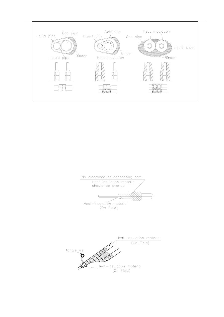
(2) Insulation for non-jointing parts and non-connection parts
wrong right
Gas pipe and liquid pipe should
not be put together to insulate
Insulate the gas pipe
(cooling only)
Insulate the gas pipe and
the liquid pipe
266
MDV-D Installation
For construction convenience, before laying pipes, use insulation material to insulate the pipes to be deal
with, at the same time, at two ends of the pipe, remain some length not to be insulated, in order to be welded and
check the leakage after laying the pipes.
(3) Insulate for the jointing area, expanding area and the flange area
Insulate for the jointing area, expanding area and the flange area should be done after checking leakage of
the pipes
Make sure there’s no clearance in the joining part of the accessorial insulation material and local
preparative insulation material.
(4) Enswathe disposal
After insulation of the pipes, do the enswathe disposal with binding belt, make sure it’s tight.
267

MDV-D Installation
6.3 Drainage pipe insulation
(1) The connection part should be insulated, or else water will be condensing at the non-insulation part.
6.4 Note
(1) The jointing area, expanding area and the flange area should be heat insulated after passing the pressure test
(2) The gas and liquid pipe should be heat insulated individually, the connecting part should be heat insulated
individually.
(3) Use the attached heat-insulation material to insulate the pipe connections (pipes’ tie-in ,expand nut ) of the
indoor unit.
7. Pipeline Installation
7.1 Pipeline facture
(1) The material of the pipeline
Standard: lubricity inside, small friction resistance, not absorbing moisture, incombustibility, erosion
resistance, longevity, lightness, good sealing, no accumulation, easily cleaning. Normally, we can select
galvanization steel, aluminum, and plastic. For short pipeline, we can also select aluminum foil board.
(2) The process of the piping
The process of the piping should meet the requirements of the design. The process can be done in
subsection. And every subsection’s length is about between 1.8m and 4m. In order to improve the
pipeline’s rigid, a rib often be added at the outer surface. The pipeline usually adopts the flange to
connect and add the asbestos washer with thickness 3mm to prevent air leakage. At present, the sealant
and adhesive tape are also used to seal.
(3) The shape of the pipeline
Type of the pipeline
The pipeline has ground and direct shape. The compare is as follows:
Ground pipeline
Square pipeline
less material, need large space, its’ bending
pipe and three-way pipe need long distance
need small space, can be equipped easily,
adopt direct pipeline with the rate below 2.5
between length and width
268
MDV-D Installation
specification of the pipeline
Ground pipeline should first adopt the basic series, the ratio of the long side and the short side of the
direct pipeline should not be larger than 4:1. Pipeline should be outer diameter or outer border. Brick
and concrete pipeline should be inner diameter or inner border.
Pipeline diameter
Basic
series
Accessorial
series
Basic
series
Accessorial
series
Basic
series
Accessorial
series
100 80/90/100 300 300/320 900 850/900
120 110/120 360 340/360 1000 950/1000
140 130/140 400 380/400 1120
1060/1120
160 150/160 450 420/450 1250
1180/1250
180 170/180 500 480/500 1400
1320/1400
200 190/200 560 530/560 1600
1500/1600
220 210/220 630 600/630 1800
1700/1800
250 240/250 700 670/700 2000
1900/2000
280 260/280 800 750/800
(4) The thickness of the pipeline
The following table takes steel pipeline as an example, the other thickness of the pipeline material can be
looked up in the correlative standard of the book <construction and accept criterion>
Square pipeline
Type Pipeline
diameter
(long border )
dimension
Ground pipeline
Middle and low
pressure system
High pressure
system
80—320 0.5 0.5
340—450 0.6 0.6
480—630 0.8 0.6
670—1000 0.8 0.8
0.8
1120—1250 1.0 1.0 1.0
1320—2000 1.2 1.0 1.2
2500—4000 1.2 1.2 1.2
7.2 Pipeline Installation
(1) When the pipeline and its accessories pass through wall, board and roof, holes should be reserved in advance,
and the dimension and location should meet the design demand.
(2) The configure of the spot pipeline connection should not reduce its valid section.
(3) The hanger can’t be set at the air-outlet, valve, examination-port and automatic control machine. And the
269
MDV-D Installation
suspender isn’t suitable to be fixed at the flange.
(4) The configure of the spot pipeline connection should not reduce its valid section.
Horizontal installation
Vertical installation
Bright Installation
δ≤3mm/m ∆≤20mm
δ≤2mm/m ∆≤20mm
Hidden Installation
Right position, no obvious windage
δ—windage permeter ∆—total windage
(5) The hanger of insulated pipeline should set outside the insulation layer and can’t injure the insulation
layer.
(6) The distance between hangers:
Diameter (long border)
dimension< 400mm
Diameter (long border)
dimension≥ 400mm
Horizontal distance
≤4mm
≤3mm
Vertical distance
≤4mm the part for fixing of every vertical pipeline
should not less than 2
7.3 Posit the air-outlet
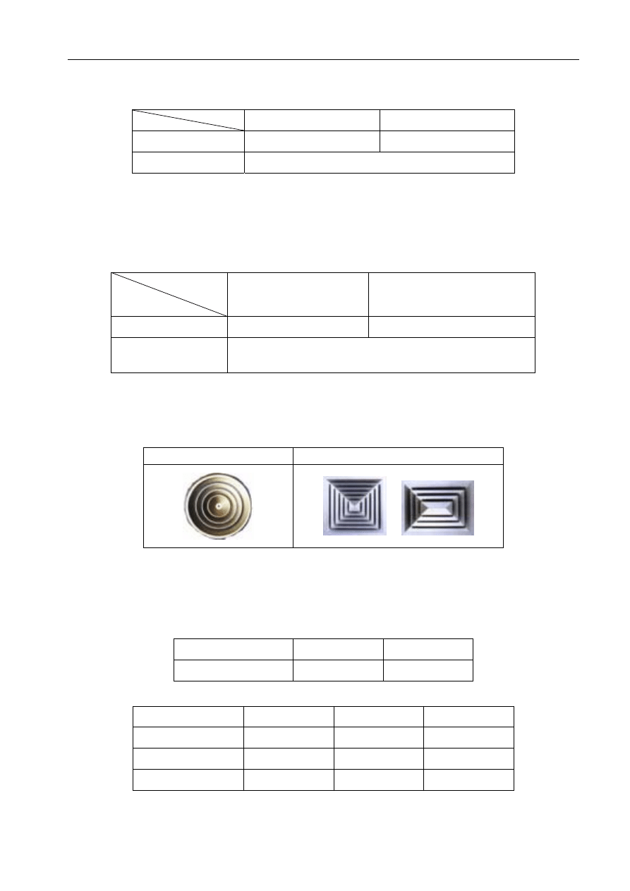
(1) Type
Familiar outlet type: Louver outlet, disperser and linear outlet.
Linear
outlet
(2) Specification
The specification of the air-outlet should be based on outer-diameter and outer-line.
allowed windage of round air-outlet (mm)
diameter
≤250 >250
allowed windage
0 -2 0 -3
allowed windage of rectangle air-outlet (mm)
270
Diameter <300
300 800 >800
allowed windage
0 -1 0 -2 0 -3
Catercorner length
<300
300 500 >500
Two catercorner
≤1
≤2
≤3

MDV-D Installation
(3) Posit the outlet
Air-outlet:
In the design and construction, no matter cooling and heating, cooling and heating are sent to places
through air-outlet, so it’s important to select the right air-outlet.
Many factors limit the selection of air-outlet, for example:
Indoor fitment
Airflow in the room
Installation and connection type of the air-outlet
The following issues should be noted:
Try to assure the equality of the indoor parameters (especially the temperature)
Prevent short-circuit of the air-inlet and air-outlet
prevent bolding cold air directly to people in summer
Air-inlet:
The air-inlet shouldn’t be set at places where people stays long to prevent short-circuit and
open-circuit. If adopting side-sending, it is suitable to set at the same side of the air-outlet.
For side air-inlet, normally, it is set under the same side. If adopting parallel air-sending, the air-inlet
also is set underside mostly. In order to avoid dust and filter, the height from the underline of the
air-inlet to the ground should at least keep 0.15m. For high big workshops, it is suitable to add air-inlet
or discharge air-let to discharge surplus-heat.
The distance from the air-inlet of the scatter setting to the wall should not less than half of the space
between scatter setting.
Fresh air-let:
Fresh air-let should be set at clean places and far away from discharge air-let.
Fresh air-let should be set upside the discharge air-let.
Fresh air-let should be set in the shade and avoid roof and west-wall. The distance from the ground is
at least 2m and 1m in case of green ground. And shutter is needed under the air-let.
(4) Facture and installation
Try to use the inlet panel of MIDEA brand.
Set a static-pressure box in the outlet to remove some noise
271
MDV-D Installation
Pay attention to the insulation of pipeline and the condensing water in the outlet.
The appearance of the air-outlet hasn’t obvious impress, nick and spot. The color should be consistent and
welding points should be lubricous.
The match between inner sphere and outer sphere of sphericity air-outlet should rotate freely and isn’t
flexible after orientation.
The diffusing loop and modulation loop of the scatter setting should be at the same axis and space
distributing in radial direction should be even.
8. Electric Installation
Electric installation must be carried out according to National Standard.
This chapter just for reference.
8.1 Brief Introduction
All wire, part and material must conform to concerning national standards.
All wiring work must be done by qualified person.
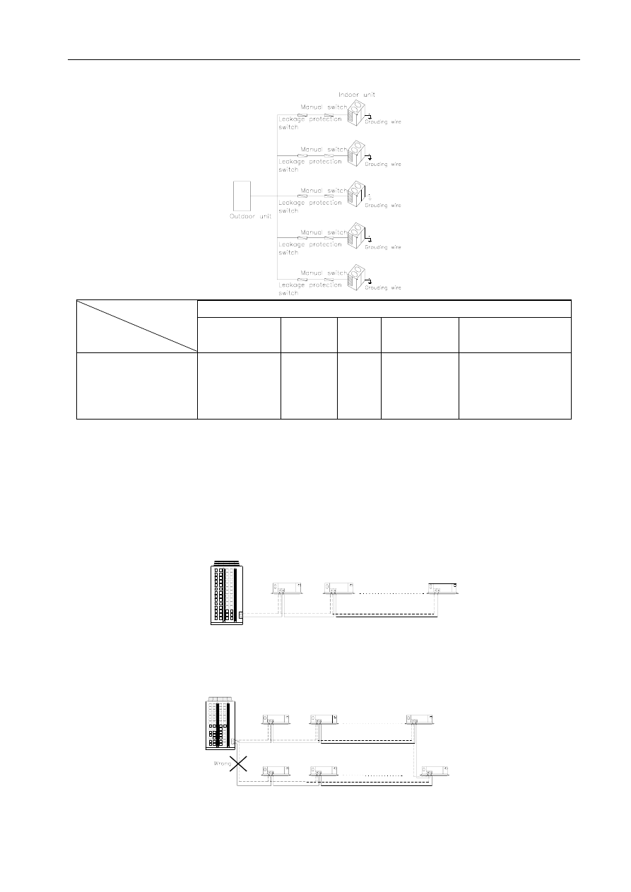
Must ground well.
8.2 Power circuitry installation
Sketch map of power wiring
Selecting Creepage breaker
The creepage protection switch is consist of creepage
, zero-phase current mutual
inductance and automatic switch. It is applicable to AC 50Hz, single-phase, 220V or three-phase,
380V. It can prevent person from getting an electric shock and protect device from creepage. In
normal case, it can provide conversion for circuit.
Selecting creepage breaker
272
MDV-D Installation
Selecting the creepage breaker according to 1.5-2 times of the sum of loading rated current.
Selecting Manual Switch
When the power doesn’t supply separately, selecting the manual switch and fuse capacity according to
the total capacity.
Total capacity (HP)
Manual switch (A)
Fuse (A)
10—14 100 75
15—18 100 100
19—28 150 150
29—36 200 200
37—47 300 250
48—50 300 300
Selecting wiring specification
The following wiring specification just aim at Fluorin resinoid insulating wire, if use others, please
refer to the concerning national standard.
Normal Fluorin resinoid insulating wire
Model Name
BV
Fluorin resinoid insulating wire, copper-core
BLV
Fluorin resinoid insulating wire, aluminum-core
BVR
Fluorin resinoid insulating soft wire, copper-core
BVV
Fluorin resinoid insulating wire, copper-core, round-type
BLVV
Fluorin resinoid insulating wire, aluminum-core, round-type
BVVB
Fluorin resinoid insulating wire, copper-core, flat-type
BLVVB
Fluorin resinoid insulating wire, aluminum-core, flat-type
BV-105
Fluorin resinoid insulating wire, copper-core, heat-endurance 105
RV
Fluorin resinoid insulating connecting soft wire, copper-core
RVB
Fluorin resinoid insulating connecting wire, copper-core, flat-type
RVS
Fluorin resinoid insulating connecting wire, copper-core, twist-type
RVV
Fluorin resinoid insulating connecting soft wire, copper-core, round-type
RVVB
Fluorin resinoid insulating connecting soft wire, copper-core, flat-type
RV-105
Fluorin resinoid insulating connecting soft wire, copper-core, heat-endurance 105
Indoor power supply wiring
Indoor power supply
Power wiring
Power supply
Manual switch
Fuse
20m below
50m below
1-phase
220-240V 50Hz
15 A
2.5 mm
2
6.0 mm
2
Outdoor power supply wiring
273
MDV-D Installation
Sketch map of outdoor wiring
Outdoor power suply
Item
Model
Power supply
Manual
switch
Fuse
Creepage
protector
Power wiring
10HP
380V 3N
50Hz
60A 50A
100mA 0.1sec
below
6.0 mm
2
or 6.0
mm
2
above
(According to real
wiring distance)
Note: For 20HP and 30HP, wiring separately according to 10HP outdoor power wiring specification.
8.3 Control Wiring Connection Method
(1) Control Wiring Connection
Correct Connection
Typical Wiring Mistake
Part of Control wiring of Indoor units are connected at ring-type by mistake
274
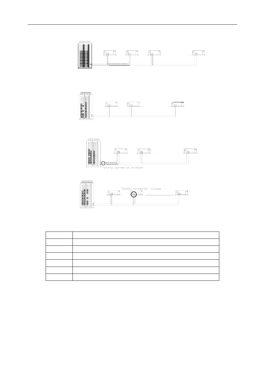
MDV-D Installation
art of Control wiring of Indoor units are connected at star-type by mistake
Control wiring of all indoor units are connected at star-type by mistake
Polarity connection mistake for control wiring between outdoor/indoor units
Polarity connection mistake for control wiring between indoor units
Specification of Control Wiring
Normal shield wires is as following:
Model Item
AVP
Fluorin resinoid insulating shield wire, copper-core
AVP-105
Fluorin resinoid insulating shield wire, copper-core, heat-endurance 105
RVP
Fluorin resinoid insulating shield wire, copper-core
RVP-105
Fluorin resinoid insulating shield wire, copper-core, heat-endurance 105
RVVP
Fluorin resinoid insulating shield soft wire, copper-core
RVVP1
Fluorin resinoid insulating twist shield soft wire, copper-core
275
MDV-D Installation
8.4 Wiring Diagram (Indoor/Outdoor)
MDV-D100W/S(N2) MDV-D140W/S(N2) Wiring Diagram
(2) MDV-D280W/S(N2) Wiring Diagram
276
MDV-D Installation
(3) MDV-D560W/S(N2) Wiring Diagram
(4) MDV-D840W/S Wiring Diagram
277
MDV-D Installation
8.4 Wiring Diagram (Indoor/CCM)
278
MDV-D Installation
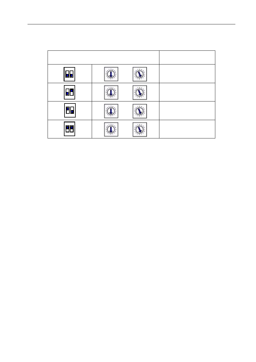
8.5 Address Setting
Address setting of outdoor units
The following table is applicable to communication address setting of main and auxiliary outdoor unit.
Address setting of outdoor unit
Main
20HP
Auxiliary
Main
Auxiliary 1
30HP
Auxiliary 2
Note: SW3: Address setting switch for auxiliary outdoor unit
SW4: Address setting switch for main outdoor unit
Address setting of indoor units
Address setting of indoor units
Indoor unit
ENC2
No. 1
0
No. 2
1
No. 3
2
…… ……
Indoor unit
No.0—15
No. 16
15
No. 17
0
No. 18
1
No. 19
2
…… ……
Indoor unit
No.16—31
No. 32
15
279
MDV-D Installation
280
(3) Network address setting(S1/S2)
I
t must set address before using NIM. Every air-conditioner in network has only one network address to
distinguish each other. Address code of air-conditioner in LAN is set by code switch on NIM, and the set range is
0-63.
Address Set
Address Code
~
00 ~ 15
~
16 ~ 31
~
32 ~ 47
~
48 ~ 63
Document Outline
- 1. Summarize of Installation
- 1.8 Install outdoor unit
- Note: the calculation results must be correct.
- 2. Installation of Outdoor unit
- 3. Installation of Indoor unit
- 4. Installation of Refrigerant Pipe
- 4.4 Dimension of refrigerant distributor
- BY51 2) BY101
Wyszukiwarka
Podobne podstrony:
Jednostki wewnetrzne MDV D
instalacja oświetlenia zewnętrzna
Gotowy Windows do instalacji na zewnętrznym dysku USB
Instalacja zewnętrzna
DBR Instrukcja instalacji STATISTICA wersja jednostanowiskowa 10 PL
Instalacje oświetlenia zewnętrznego, Elektryka
Jednostki zębate o zazębieniu zewnętrznym
acad podręcznik instalacji jednostanowiskowej
Instalacja i oswietlenie zewnetrzne
projektowanie zewnętrznych instalacji kanalizacyjnych k2 kan z PP
ZwCAD2007 instalacja programu wersja jednostanowiskowa
Instrukcja projektowania i budowy zewnetrznych instalaci kanalizacyjnych z PP KACZMAREK
Kontrola zewnetrzna w jednostkach samorzadu terytorialnego
Instrukcja instalacji Analizy Marketingowe wersja jednostanowiskowa
więcej podobnych podstron