Installation, care and maintenance
4630, 4640, 4650, 4660, 4670, 4680
892344/08
2
CONTENTS
Page
Page
Operation
____________________________ 18
Before starting ___________________________ 18
During operation __________________________ 18
Care and maintenance
_____________ 19
Safety precautions ________________________ 19
Service __________________________________ 19
Changing the oil __________________________ 22
Replacing the propeller ____________________ 23
Lifting device _____________________________ 24
Tools and accessories
_____________ 25
Tools ___________________________________ 25
Start and control equipment ________________ 25
Seal protection ___________________________ 25
Flush protection __________________________ 25
Cutting rings _____________________________ 26
Cooling jacket ____________________________ 26
Fault tracing (Troubleshooting)
___ 27
Service log
___________________________ 30
Guarantee
____________________________ 3
Data plates interpretation
__________ 4
Product description
________________ 5
Applications _____________________________ 5
Motor data _______________________________ 6
Design __________________________________ 7
Materials ________________________________ 9
Weights _________________________________ 9
Performance curves for PP _________________ 10
Transportation and storage
________ 11
Installation
___________________________ 11
Safety precautions ________________________ 11
Handling equipment _______________________ 11
Mixer installation alternatives _______________ 12
Flange mounted mixer _____________________ 12
PP-pump installation ______________________ 13
Electrical connections
_____________ 15
CLS and FLS sensors ______________________ 17
General Danger:
Non-observance given to safety
instructions in this manual, which
could cause danger to life have
been specifically highlighted with
this general danger symbol.
High Voltage:
The presence of a dangerous volt-
age is identified with this safety
symbol.
Identification of safety and warning
symbols
This “Installation, Care and Maintenance”
applies to the following versions of the
4600-series:
4630
4630.410, 4630.490,
PP4630.410, PP4630.490
4640
4640.410, 4640.490,
PP4640.410, PP4640.490
4650
4650.410, 4650.490,
PP4650.410, PP4650.490
4660
4660.410, 4660.490,
PP4660.410, PP4660.490
4670
4670.410, 4670.490,
PP4670.410, PP4670.490
4680
4680.410, 4680.490,
PP4680.410, PP4680.490
3
Flygt guarantees that a spare parts stock will be kept
for 15 years after the manufacture of this product has
been discontinued.
The manufacturer reserves the right to alter perfor-
mance, specification or design without notice.
Official approval applies only providing:
— that the product is used under condition
described in the care and maintenance
instructions and in applications for which it
is intended;
— that the monitoring equipment incorporated
in the product is correctly connected;
— that all service and repair work is done by a
workshop authorized by Flygt;
— that genuine Flygt parts are used.
GUARANTEE
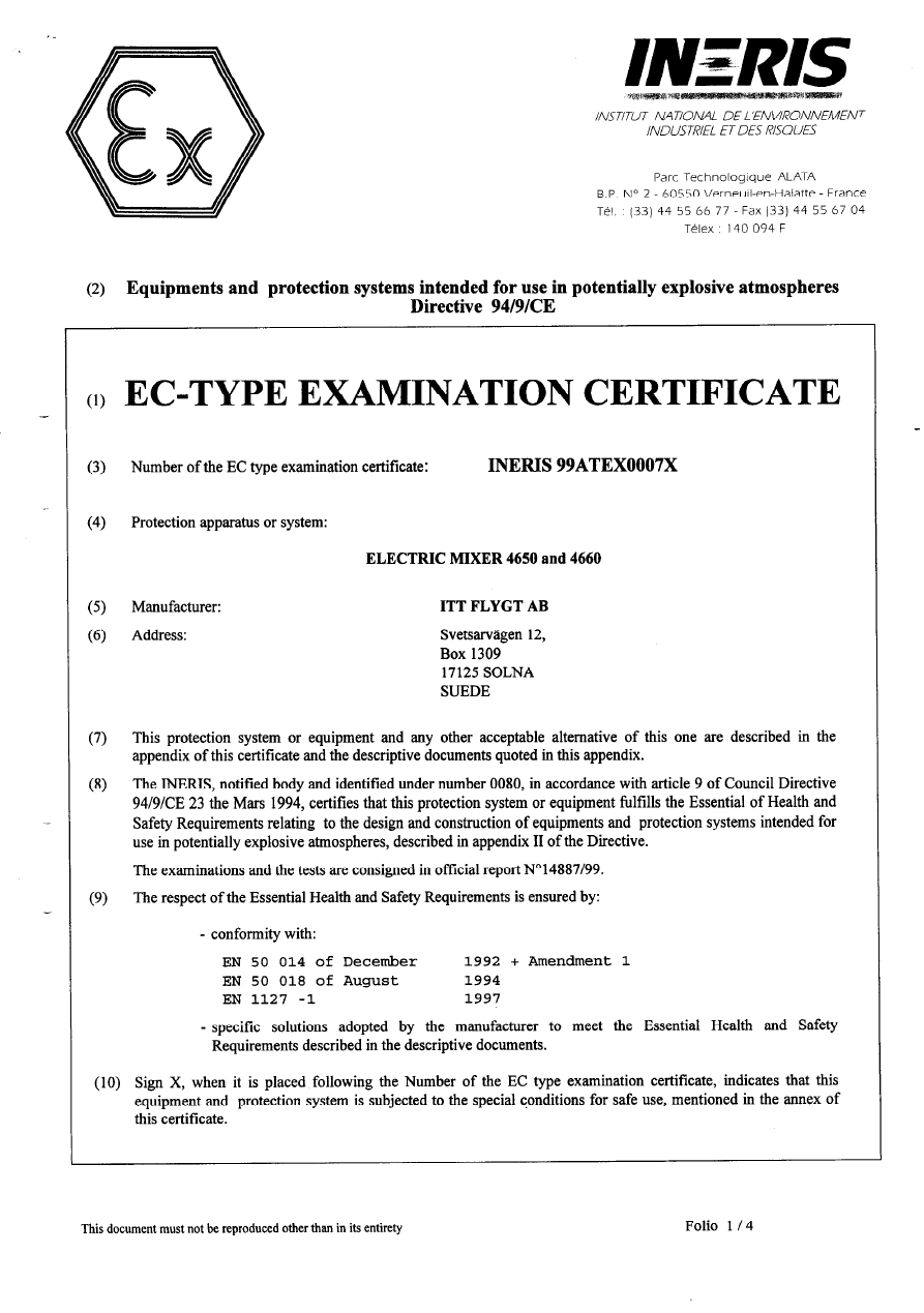
The explosion proof version (Ex-approved) is
designed for use in explosive environments in
accordance with approvals stated on page 4.
Thermal contacts must always be
used on Ex-approved machine due
to approval conditions.
All work on the explosion-proof
motor section must be performed by
personnel authorized by Flygt.
Flygt disclaims all responsibility
for work done by untrained,
unauthorized personnel.
NOTES FOR EXPLOSION
APPROVED MACHINES
Flygt undertakes to remedy faults in products sold by
Flygt provided:
— that the fault is due to defects in design, materials
or workmanship;
— that the fault is reported to Flygt or Flygt’s repre-
sentative during the guarantee period;
— that the product is used only under conditions de-
scribed in the care and maintenance instructions
and in applications for which it is intended;
— that the monitoring equipment incorporated in the
product is correctly connected;
— that all service and repair work is done by a work-
shop authorized by Flygt;
— that genuine Flygt parts are used.
Hence, the guarantee does not cover faults caused by
deficient maintenance, improper installation, incorrect-
ly executed repair work or normal wear and tear.
Flygt assumes no liability for bodily injuries, material
damages or economic losses beyond what is stated
above.
According to rules the Ex-approved
machine must always work com-
pletely submerged in the liquid.
4
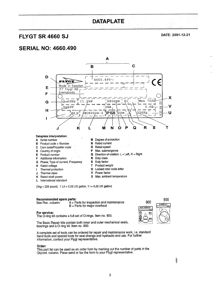
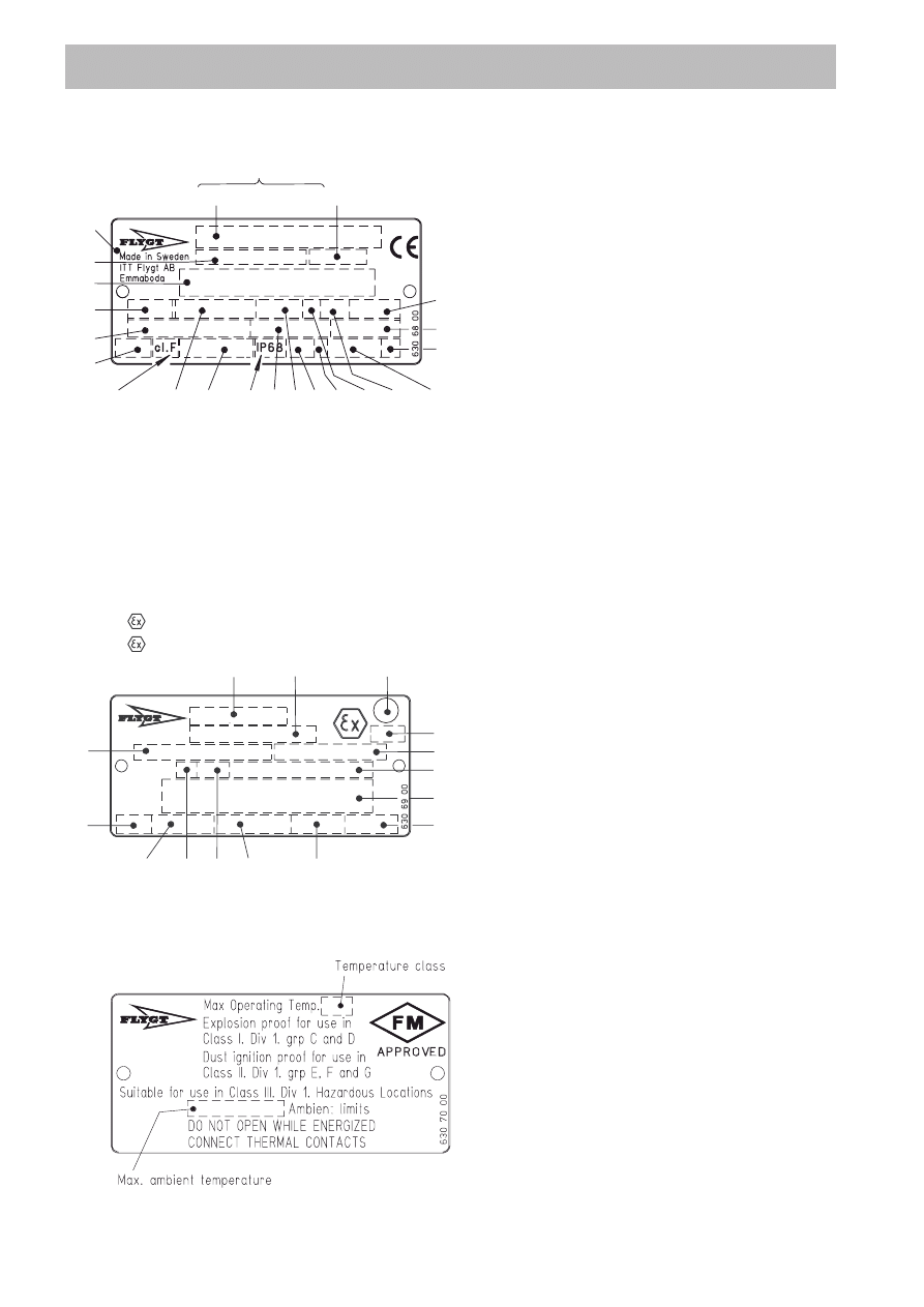
DATA PLATE INTERPRETATION
GENERAL DATA PLATE
A
Serial number
B
Product code + Number
C
Curve code
D
Country of origin
E
Product number
F
Additional information
G
Phase; Type of current; Frequency
H
Rated voltage
I
Thermal protection
J
Thermal class
K
Rated shaft power
L
International standard
M
Degree of protection
N
Rated current
O
Rated speed
P
Max. submergence
Q
Direction of rotation: L=left, R=right
R
Duty class
S
Duty factor
T
Product weight
U
Locked rotor code letter
V
Power factor
X
Max. ambient temperature
A
Approval
B
Approval authority + Approval Number
C
Approval for Class I,
D
Approved drive unit
E
Stall time
F
Starting current/Rated current
G
Duty class
H
Duty factor
I
Input power
J
Rated speed
K
Controller
L
Additional information
M
Max. ambient temperature
N
Serial Number
O
ATEX marking
D
A
N
K
L
M
C
B
F
E
G
I
J
H
O
M
L
N
V
U
T
R S
Q
P
O
I
J
K
H
G
F
E
D
B
C
X
A
APPROVAL PLATES
Always together with the general data plate.
EN: European Norm,
ATEX Directive
EN 50014, EN 50018, EN 1127-1,
ll 2 G EEx dllB T4
I M2 EEx dl (only 4650 and 4660)
FM: Factory Mutual,
Class l Div 1 Grp C and D
Class ll Div 1 Grp E, F and G
5
Applications
For other applications than mentioned below, contact
your nearest Flygt representative for information.
Mixer
The mixer is intended to be used in:
— sewage plants, sludge tanks and aeration basins,
anaerobic or oxygen saturated water, presence of
rags etc.
— industrial processes, heavy environments with high
demands of operational security, water with usually
metallic salt, paper pulp and cellulose, food and
chemical industry.
— industrial sewage processes, some wearing, pres-
ence of rags and metallic salt.
— mineral slurries with high wearing characteristics,
presence of rags acceptable.
— fish farms and current creating in dams, oxygen
supply, demands of environmental approved mate-
rials. Sweet, brackish or salt water.
— liquid manure, presence of straw, strings, board-
pieces etc, floating sludge with a thickness of up to
1 meter (3.3 ft).
The mixer is designed for use in many different situa-
tions where high flow capacity in relation to power
consumption is required.
The mixing effect is dependent upon the density and
the viscosity of the liquid and on the volume/shape of
the tank.
More than one mixer is required for larger tanks.
Flange mounted mixer
The flange mounted mixer is intended to be used in:
— Oil industry/oil tanks.
— Pulp and paper industry.
— Various process industry.
PP-pump
The PP-pump is intended to be used for:
— clean water pumping at land drainage,
— irrigation and controlling of water course systems,
— waste water treatment, recirculation within treat-
ment processes or return sludge pumping.
The hydraulic parts together with the installation ac-
cessories are specially designed to optimize the per-
formance of the pump.
PRODUCT DESCRIPTION
General Description
These care and maintenance instructions apply to
both the standard version and the explosion proof
version of the submersible Flygt mixers and PP-
pumps.
The explosion proof version (Ex-approved) is
designed for use in explosive environments in
accordance with the approvals, see page 4.
The submersible mixer and the PP-pump in the 4600-
series have the below features:
— direct driven electric multipole motors.
— propellers with different diameters and blade
angles.
— different materials.
— different seals.
— different installation modes.
The pH of the liquid: 1—12.
Liquid temperature: max. 40°C (105°F).
Warm liquid version max. 90°C (195°F).
Depth of immersion: max. 20 m (165 ft).
Only Ex-approved machines may be
used in explosive or flammable
environments or for mixing/pumping
flammable liquids.
6
4680
60 Hz, 1.9 kW (2,5 hp),
3 phase, 8 pole,
855**r/min
Voltage
Rated
Starting
current
current
V
A
A
200
9.3
29
220
9.6
33
230
8.3
28
400
4.8
16
460
4.2
14
480
4.3
15
575
3.4
11
600
3.4
12
60 Hz, 30 kW (40 hp),
3 phase, 16 pole,
435** r/min
Voltage
Rated
Starting
current
current
V
A
A
200
194
525
220
179
490
230
160
430
400
93
250
460
87
236
480
84
228
575
66
178
600
69
189
1000
1)
38
103
50 Hz, 25 kW,
3 phase, 16 pole,
365* r/min
Voltage
Rated
Starting
current
current
V
A
A
200
160
450
230
139
390
400
80
225
415
77
217
500
66
187
550
58
161
690
1)
46
129
1000
1)
35
100
1)
Not FM-approved
*)
400 V
**)
460 V
1)
Not FM-approved
*)
400 V
**)
460 V
Motor data
Data for liquid max 40°C (105°F)
4630
50 Hz, 1.5 kW,
3 phase, 8 pole,
710* r/min
Voltage
Rated
Starting
current
current
V
A
A
200
8.3
27
220
9.1
30
230
7.2
23
380
4.4
14
400
4.2
14
415
4.0
13
500
3.3
11
1000
1)
1
2.0
6.2
50 Hz, 5.5 kW,
3 phase, 12 pole,
470* r/min
Voltage
Rated
Starting
current
current
V
A
A
200
32
88
220
30
105
230
31
90
400
17
48
415
16
47
500
13
37
1000
1)
1
7.3
22
60 Hz, 6.2 kW (8.3 hp),
3 phase, 12 pole,
575** r/min
Voltage
Rated
Starting
current
current
V
A
A
200
32
93
220
32
105
230
30
92
400
18
56
460
16
51
480
16
54
575
12
38
600
12
41
4650
4640
50 Hz, 2.5 kW,
3 phase, 8 pole,
705* r/min
Voltage
Rated
Starting
current
current
V
A
A
200
14
45
220
15
51
230
12
39
380
7.4
24
400
6.5
20
415
6.5
22
500
5.5
18
1000
1)
1
3.1
10
60 Hz, 3.0 kW (4.0 hp),
3 phase, 8 pole,
855**r/min
Voltage
Rated
Starting
V
current
current
A
A
200
15
51
220
16
59
230
13
46
400
7.8
27
460
6.7
23
480
6.9
25
575
5.4
19
600
5.5
20
50 Hz, 10 kW,
3 phase, 12 pole,
475* r/min
Voltage
Rated
Starting
current
current
V
A
A
200
55
148
220
56
170
230
48
136
380
32
95
400
29
87
415
30
92
500
23
67
1000
1)
13
41
4660
60 Hz, 11.2 kW (15.0 hp),
3 phase, 12 pole,
575** r/min
Voltage
Rated
Starting
current
current
V
A
A
200
58
178
220
60
202
230
51
156
400
32
105
460
27
84
480
28
96
575
22
71
600
22
75
4670
50 Hz, 13 kW,
3 phase, 16 pole,
365* r/min
Voltage
Rated
Starting
current
current
V
A
A
200
89
234
230
81
216
400
44
117
415
44
118
500
36
94
550
32
85
690
1)
26
68
1000
1)
20
53
60 Hz, 14.9 kW (20 hp),
3 phase, 16 pole,
435** r/min
Voltage
Rated
Starting
current
current
V
A
A
200
98
260
220
90
238
230
86
229
400
50
133
460
48
127
480
46
121
575
34
91
600
36
97
1000
1)
20
53

7
1
2
3
4
5
6
6
7
8
4081
1
12
9/10/11
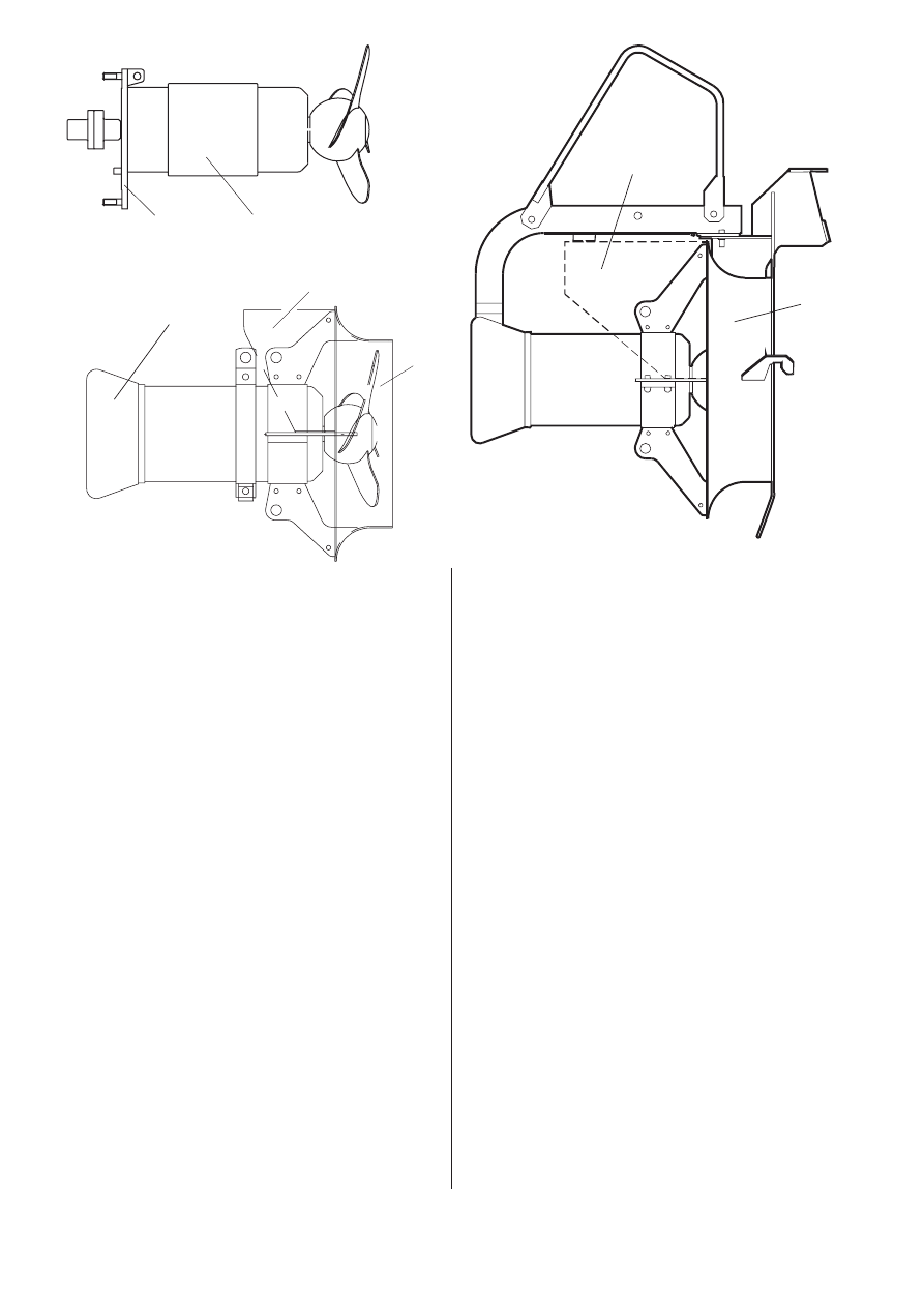
Design
See also “Electrical connections” and separate instruc-
tions for starter equipment.
The machine can be equipped with sensors, CLS for
sensing water in the oil and/or FLS for sensing water
in the stator casing. The CLS sensor is not applicate
for Ex-approved machines.
NOTE! 4630 and 4640 can only be equipped with FLS.
4. Shaft
The motor shaft is delivered with the rotor as an inte-
gral part.
The motor shaft is completely sealed and will not
come in contact with the liquid.
5. Shaft seals
Mechanical face seals plug-in type, which combines
an inner and an outer seal into one, rigid unit.
6. Bearings
The shaft is carried in one single-row angular contact
ball bearing and a single-row cylindrical roller bearing
together with a single-row angular contact ball bearing.
The bearings are dimensioned for more than 100 000
(L 10 aa) hours of operation.
7. Oil casing
The oil lubricates and cools the seals and acts as an
additional barrier against penetrating liquid.
Pressure build-up within the oil casing is reduced by
means of a built-in air volume.
Cable entry
The cable entry has two compressible rubber bush-
ings to seal off and to relieve the cable.
1. Junction box
The junction box is completely sealed off from the
surrounding liquid and the stator casing.
2. Motor
Squirrel-cage 3-phase induction motor for 50 Hz or 60
Hz.
The motor is started by means of direct on-line start.
The motor can be run continuously or intermittently
with a maximum of 15 evenly spaced starts per hour.
The stator is insulated in accordance with class H
(180°C, 355°F). The motor is designed to supply its
rated output at ± 5 % variation of the rated voltage.
Without overheating the motor, ± 10 % variation of the
rated voltage can be accepted provided that the motor
does not run continuously at full load. The motor is
designed to operate with a voltage imbalance of up to
2 % between the phases.
3. Monitoring equipment
The stator incorporates three thermal contacts con-
nected in series.
The thermal contacts open at 125°C (260°F).
NOTE! The thermal contacts should be connected for
liquid temperature up to 40°C (105°F) and always for
Ex approved machines.
8
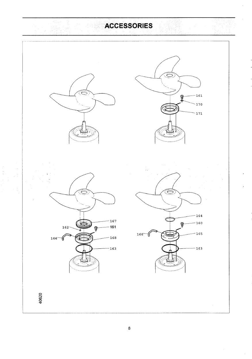
8. Propeller
The propeller is three-bladed and the blades have a
large width and a thin profile, a smooth surface and
are back-swept. This gives a highly efficient and clog-
free operation.
The propeller angle can be adjusted to meet
requirements. Angles between 4° and 19° are
possible, but restricted upwards depending on version
and applications due to available power.
9. Flush protection
The mixer and the PP-pump can be equipped with
accessories for water or air flushing systems. Flushing
the propeller hub area and the outer seal reduces the
risk of sticking when mixing reactive slurries.
10. Cutting rings
The propeller can be equipped with cutting rings to
prevent clogging of the hub area.
The cutting rings can be used with or without flushing.
These are intended to be used for mixer applications,
where liquids with long fibres are to be mixed.
11. Seal protector
The mixer and PP-pump can be equipped with seal
protector to prevent clogging.
12. Fixing plate
The mixer is available with two types of fixing plate,
one for guiding bar installation and one for flange
mounted mixer.
13. Cooling jacket
Normally the stator is cooled by the surrounding liquid.
External cooling (cooling jacket) is available as option.
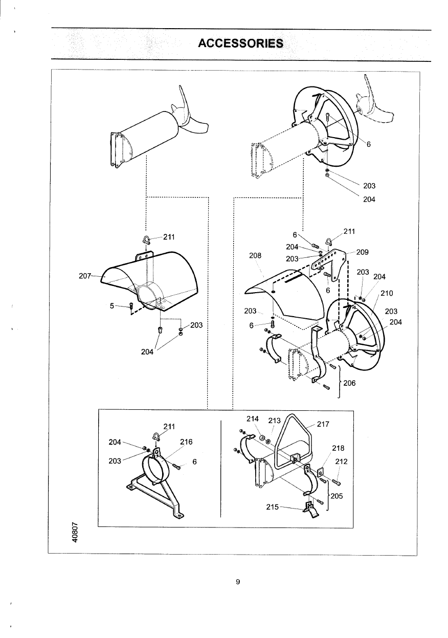
14. Vortex protection shield
In order to avoid vortex the machine can be equipped
with a protective shield.
15. Jet ring for mixer
The mixer can be operated with or without a jet ring.
The jet ring improves the efficiency and directs the jet.
NOTE. Operation without jet ring affects the
power consumption.
16. Inlet cone for PP-pump
The inlet cone is designed to give the best influence
on the created flow .
Discharge connection for PP-pump
The function of the discharge connection is to fix the
inlet cone onto a pipe or a diffusor.
Guiding equipment for PP-pump
The guiding equipment consists of two pipes (guide
bars) and upper guide bar holders.
Installation for PP-pump
The PP-pump should be installed horizontally on a
wall and guided vertically along the wall.
The pump slides down along guide bars and connects
automatically to the discharge connection. The flange
of the inlet cone directs the pump at guiding and
secures the correct position on the discharge con-
nection.
14
16
15
14
12
12
11
40340
12
13

9
Weights
Max. weight of mixer and PP-pump irrespective of
material, including lifting device but without motor
cable is:
4630
Mixer without jet ring
55 kg ( 121 lb)
Mixer with jet ring
60 kg ( 132 lb)
Flange mounted mixer
1)
70 kg ( 154 lb)
Cooling jacket
2)
3.3 kg ( 7.3 lb)
PP-pump
77 kg ( 170 lb)
4640
Mixer without jet ring
60 kg ( 132 lb)
Mixer with jet ring
70 kg ( 154 lb)
Flange mounted mixer
1)
75 kg ( 165 lb)
Cooling jacket
2)
3.3 kg ( 7.3 lb)
PP-pump
85 kg ( 187 lb)
4650
Mixer without jet ring
150 kg ( 330 lb)
Mixer with jet ring
175 kg ( 386 lb)
Flange mounted mixer
1)
150 kg ( 331 lb)
Cooling jacket
2)
7.5 kg (16.5 lb)
PP-pump
204 kg ( 450 lb)
4660
Mixer without jet ring
190 kg ( 419 lb)
Mixer with jet ring
220 kg ( 485 lb)
Flange mounted mixer
1)
190 kg ( 419 lb)
Cooling jacket
2)
7.5 kg (16.5 lb)
PP-pump
251 kg ( 553 lb)
4670
Mixer without jet ring
285 kg ( 628 lb)
Mixer with jet ring
350 kg ( 772 lb)
Flange mounted mixer
1)
300 kg ( 661 lb)
Cooling jacket
2)
11 kg ( 24 lb)
PP-pump
410 kg ( 904 lb)
4680
Mixer without jet ring
405 kg ( 893 lb)
Mixer with jet ring
470 kg (1036 lb)
Flange mounted mixer
1)
415 kg ( 915 lb)
Cooling jacket
2)
11 kg ( 24 lb)
PP-pump
533 kg (1175 lb)
1)
without jet ring and lifting device
2)
not including tubes and couplings
Materials
Denomination
Materials
Flygt No
EN
ASTM
Propeller
Stainless
0344.
1.4432
316L
steel
2343.02
or
Alloyed white
0314.
GLJ 250 A 532
iron (L102)
0466.20
(ALLOYIIIA)
Major castings
1
Cast iron
0314.
—
A48
0125.00
No 35B
Shaft
1
Stainless
0344.
1.4021
420
steel
2303.05
Oil housing,
Vinylester
0544.
—
—
Propeller cover
SMC CR30
9585.70
Bearing casing
Aluminiun
0404.
DIN
B85A413.0
4630 and 4640
4263.10
1725/68 A1413.0
GD-AISi12
BS
1490:70
Coupling, Cooling Stainless
0344.
1.4432
316L
jacket, Tubes
steel
2343.02
O-rings, Gasket, Nitrile
0516.
—
—
Cable entry,
rubber (NBR)
2637.04
Seal sleeve,
70°IRH (black)
or
Fluorinated-
0516.
—
—
rubber (FPM)
2677.32
70°IRH (green or black with a violet dot)
Unic for mixer of General Purpose Stainless Steel (GP) ASTM 304
Jet ring, Fixing
Stainless
0344.
1.4301
304
plate, Inlet cone, steel
2333.02
Lifting clamp
Lifting device,
Stainless
0344.
1.4432
316L
Support, Seal
steel
2343.02
holder, Motor casing,
Guiding rollers, Screws,
Unic for mixer of High Grade Stainless Steel (HP) ASTM 316
Jet ring, Fixing
Stainless
0344.
1.4432
316L
plate, Inlet cone, steel
2343.02
Lifting device,
Support, Seal holder, Motor casing, Guiding rollers, Screws,
Unic for mixer of Proacid 254 (PA) ASTM S31254
Jet ring, Fixing
Proacid
0344.
1.4547
UNS
plate
2
, Inlet cone, 254
2378.02
S31254
Lifting device,
Support, Seal holder, Motor casing, Guiding rollers, Screws,
Mechanical face seals plug-in type
:
Size
Inner seals
Outer seals
O-rings
4630, 4640
CSb/Al
2
O
3
WCCR/Al
2
O
3
NBR
WCCR/Al
2
O
3
WCCR/WCCR
FPM
WCCR/Al
2
O
3
RSiC/RSiC
FPM
4650 - 4680 Csb/WCCR
WCCR/WCCR
NBR
WCCR/WCCR
WCCR/WCCR
FPM
WCCR/WCCR
RSiC/RSiC
FPM
Csb
= Carbon
AL
2
O
3
=
Aluminium oxid
WCCR
= Corrosion resistant cemented carbide
RSiC
= Silicon carbide
1)
Not exposed,
2)
Not for flange mounted mixer
10
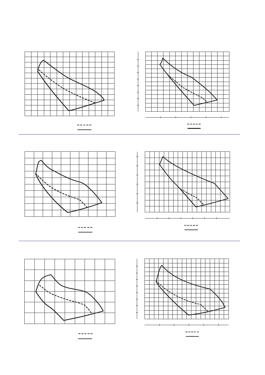
Performance curves for PP-pump
This curve shows the pump’s performance. Diffusor or exit losses are not included. The system must therefore
be considered in specific applications. If necessary contact Flygt’s “Application engineers”.
50
100
150
200
250
300
Q
l/s
0.2
0.4
0.6
0.8
1.0
1.2
H
m
1.5 kW, PP4630
2.5 kW, PP4640
50
100
150
200
250
300
Q
l/s
0.2
0.4
0.6
0.8
1.0
H
m
1000
2000
3000
4000
USgpm
0.5
1.0
1.5
2.0
2.5
3.0
ft
1.2
3.5
4.0
1.9 kW (2.5 hp) PP4630
3.0 kW (4.0 hp) PP4640
50 Hz PP4630, PP4640
60 Hz PP4630, PP4640
Q
l/s
100
200
300
400
500
600
0.4
0.8
1.2
H
m
1.6
700
800
900
2.0
5 kW, PP4650
10 kW, PP4660
100
200
300
400
600
700
Q
l/s
0.4
1.2
1.6
2.0
H
m
500
2000
6000
4000
USgpm
1
ft
800
8000
10000
12000
0.8
2
3
4
5
6
5.6 kW (7.5 hp) PP4650
11.2 kW (15.0 hp) PP4660
50 Hz PP4650, PP4660
60 Hz PP4650, PP4660
200
400
600
800
1000
1200
1400
1600
Q
l/s
0.4
0.8
1.2
1.6
2.0
2.4
H
m
13 kW, PP4670
25 kW, PP4680
200
400
600
800
1200
1400
Q
l/s
0.4
0.8
2.8
H
m
1000
5000
10000
15000
20000
USgpm
1
ft
1600
1.2
1.6
2.0
2.4
2
3
4
5
6
7
8
25000
14.9 kW (20 hp) PP4670
30 kW (40 hp) PP4680
50 Hz PP4670, PP4680
60 Hz PP4670, PP4680
11
TRANSPORTATION AND STORAGE
The mixer shall be transported and stored in a vertical
or horizontal position. Make sure that it can´t roll or fall
over.
For longer periods of storage, the mixer must be pro-
tected against moisture and heat. The propeller should
be rotated by hand occasionally to prevent the seals
from sticking together. If the mixer is stored for more
than 6 months, this rotating is mandatory.
After a long period of storage, the mixer should be
inspected before it is put into operation. Pay special
attention to the seals and the cable entry.
INSTALLATION
Safety precautions
In order to minimize the risk of accidents in connection
with the service and installation work, the following
rules should be followed:
1. Never work alone. Use a lifting harness (part No.
84 33 02), a safety line (part No. 84 33 03) and a
respirator (part No. 84 33 01), as required. Do not
ignore the risk of drowning!
2. Make sure that there is sufficient oxygen and that
there are no poisonous gases present.
3. Check the explosion risk before welding or using
electric hand tools.
4. Do not ignore health hazards. Observe strict clean-
liness.
5. Bear in mind the risk of electrical accidents.
6
Make sure that the lifting equipment is in good
condition.
7. Provide a suitable barrier around the work area, for
example a guard rail.
8. Make sure that you have a clear path of retreat!
9. Use a safety helmet, safety goggles and protective
shoes/gloves.
10. All personnel who work with sewage systems should
be vaccinated against diseases that can occur.
11. A first-aid kit must be handy.
Follow all other health and safety rules and local
codes and practices.
Handling equipment
Lifting equipment is required for handling the mixer.
The lifting device should not have a lifting capacity
which is greater than twice the weight of the mixer.
Oversized lifting equipment could cause damage if the
mixer gets stuck when being lifted.
Make sure that the lifting equipment is securely
anchored.
Ex version!
Installation of the explosion-proof
mixer must be performed by autho-
rized personnel.
In order to avoid accidents, warning
signs, for rotating propellers and ma-
chines that start automatically must
be positioned visibly. The area in the
proximinity of the machines should be fenced off.
For some installations and at certain operating
points on the performance curve the noise level
70 dB or the noise level specified for the actual
machine can be exceeded.
Always lift the machine by the lifting
device, never by the motor cable.
To reduce the risk of electric shock,
see chapter “Installation” and
“Electrical connections”.
The tank of a sewage machine sta-
tion must be vented in accordance
with local plumbing codes.
The machine is not to be installed in
locations classified as hazardous in
accordance with the national electric
code, ANSI7NFPA 70-1990.
CAUTION!
This machine is intended to run fully
submerged. Level sensing equip-
ment should be installed if there is a
possibility that the machine could be
operated at less than the “minimum
submergence depth” see chapter
“Dimensions”.
Always lift the machine by the lifting
device, never by the motor cable.
Keep out from suspended loads.
Make sure that the machine can’t
roll or fall over and injure people
or damage property.
12
Always test that the mixer will go easily up and down
the guide bar, before the mixer has been lowered to
the desired working depth.
NOTE!
If the mixer is operated without jet ring there
must be a stop function on the guide bar
to avoid the propeller from being swung
into the wall during operation.
NOTE!
Don’t position the mixer when it is operating.
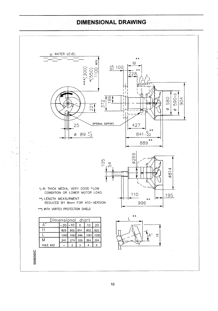
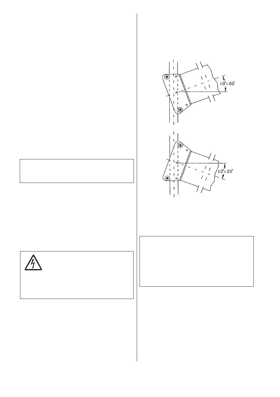
Installation in horizontal or angle position on the
guide bar
The mixer can be installed on the guide bar in hori-
zontal position or with standard angle of c:a +/-10°or
+/-20°. See Dimension drawings.
For other angle contact Flygt.
Installation alternatives for mixers
Flygt supplies equipment for a method of installation
which permits mixing over the horizontal and the verti-
cal plane.
Avoid installations where:
— there are obstacles in front of the mixer,
— the flow on the suction side of the mixer is obstruct-
ed due to the design of the tank,
— the propeller can suck down air - vortex.
To avoid vortex use a vortex protective disc or place
the mixer deeper in the liquid.
This is an absolute requirement for continuously oper-
ating mixers.
The mixer can be mounted on fixed structures, pillars,
stands, gratings, on an anchored raft etc.
When installing, keep in mind the reaction force of the
mixer, which can be up to, for:
4630
500 N
4640
900 N
4650 1800 N
4660 3000 N
4670 3900 N
4680 6600 N
NOTE!
All welded joints must be pickled and polished
before they come into contact with the liquid.
Run the cables so that they do not have any sharp
bends and are not pinched.
NOTE! The end of the cable must not be submerged.
Leads have to be above flood level, as water may
penetrate through the cable into the junction box or
the motor.
Consult your nearest Flygt representative regarding:
— choice of peripheral equipment.
— other problems in connection with installation.
In all installations, make sure that
the motor cable cannot be drawn
into the propeller.
Treat the cable as fragile, beware
that no sharp bends occure through-
out (during) installation procedure
especially by entrance flange.
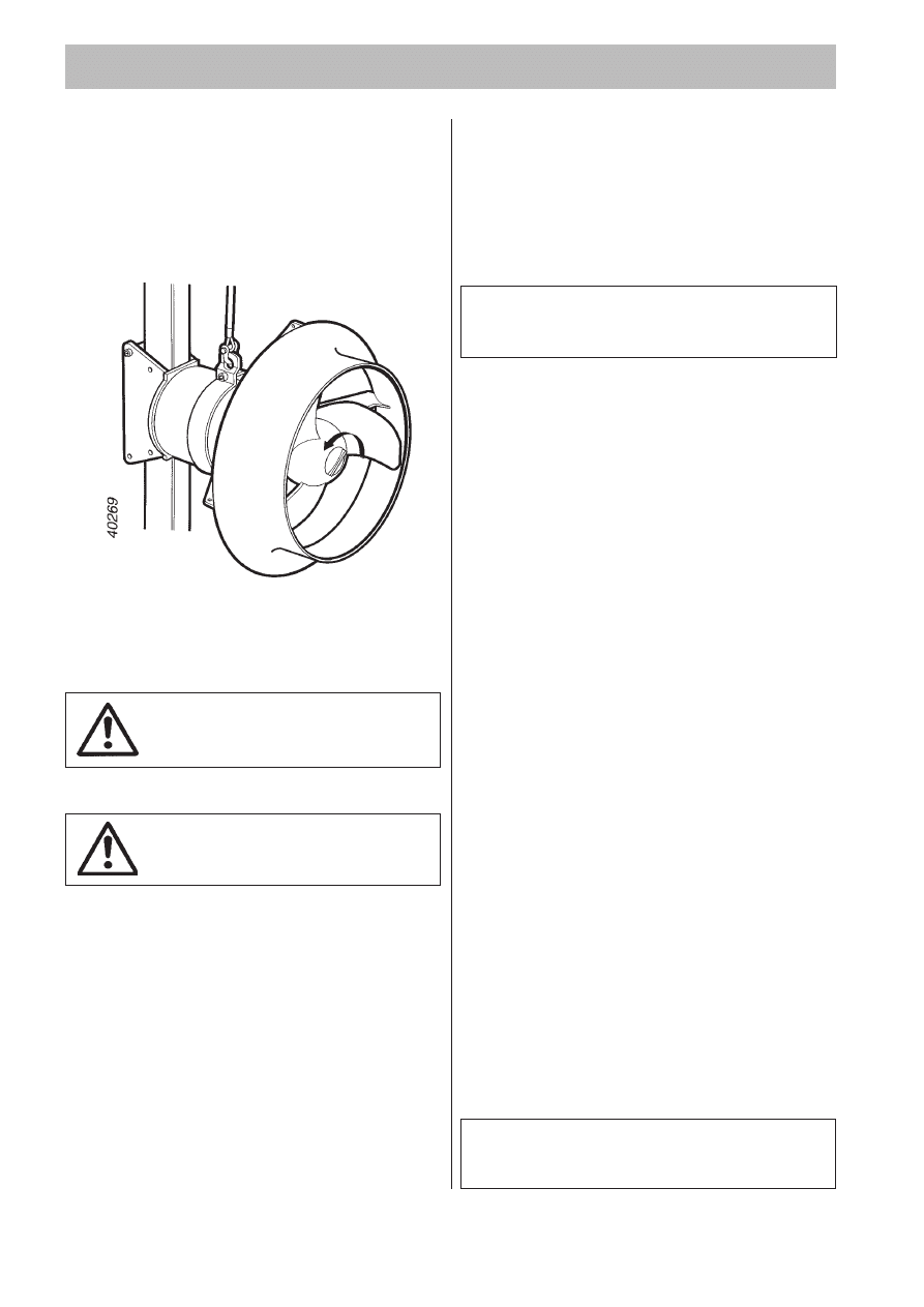
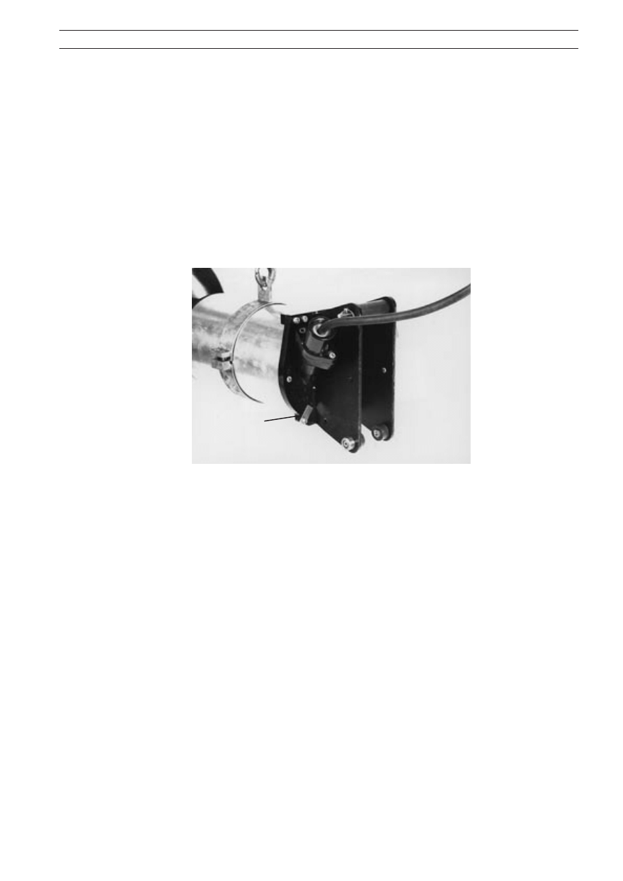
Flange mounted mixer
Flange mounted mixer is an unique method for
installing mixers in tanks where guide bar or bottom
stand installation is not the optimum solution. The
mixer is assembled to a flange mounted cover by
studs, nuts and a gasket. The flange mounted cover is
calculated according to the Swedish standard TKN-87
(Tryckkärlsnorm 1987), a standard for pressurised
vessels. The flange mounted cover is made locally,
contact your nearest Flygt representative for
information.
40315
13
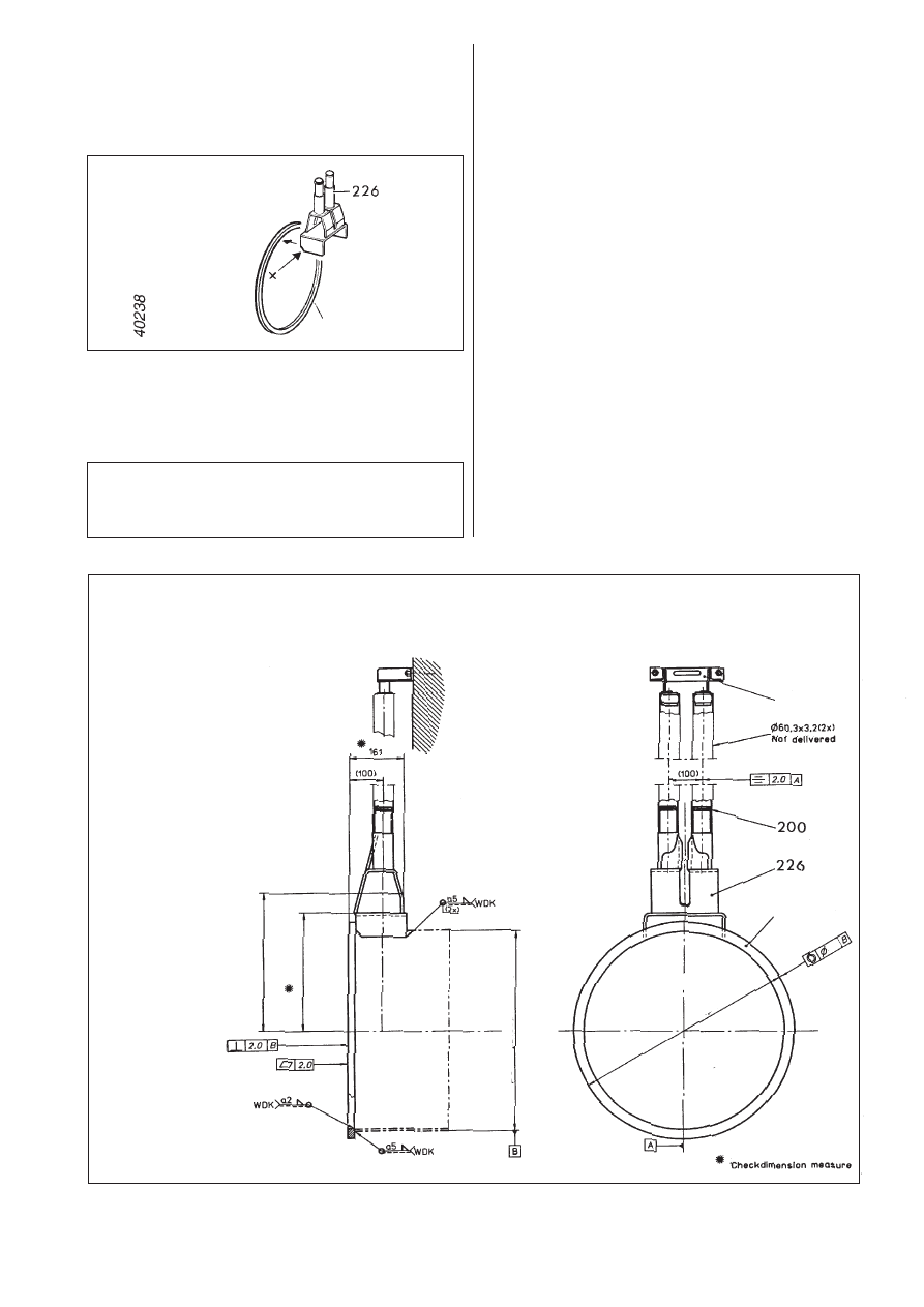
PP-pump installation
Mark out the location of the discharge connection on
the wall.
Drill a hole in the wall (a little wider than the diameter
of the tubes).
Weld together the bracket (226) and the ring (225).
NOTE! Place the bracket with the sloping (x) towards
the ring.
Centre the ring to the tube and weld the ring and
bracket together with the tube.
NOTE!
All welded joints must be pickled and polished
before they come into contact with the liquid.
The tube must have a diameter A and a wall diameter B.
4630, 4640
A
406.4 mm (16")
B
6.3 mm (0.25")
4650, 4660
A
609.6 mm (24")
B
6.3 mm (0.25")
4670, 4680
A
812.8 mm (32")
B
8.0 mm (0.31")
NOTE! It is important that the ring is welded perpen-
dicular to the tube.
Place the unit in the wall.
Carefully measure the correct guide bar length. Cut
the bars to the right length. The guide bars must have
a diameter of 60.3 mm (2.37") and a wall thickness of
3.2 mm (0.13").
Place the guide bars on the bracket, don´t forget the
O-rings (200).
Put the guide holder unit (227) on the guide bars and
mark the location of the guide holder on the wall.
Drill holes and tap in expansion bolts. Place the guide
holder and guide bars in position, tighten the bolts.
Measure the centre-to-centre distance between the
guide bars, which should be 100 mm.
It is important that the guide bars are mounted
vertical, use a plumb line.
Tighten around the tube and check that the discharge
connection will be fixed in the wall.
4630, 4640
AB
Ø 406 (DIN2458 Ø 406.4 x 6.3)
C
Ø 460
D
3.0
E
299
F
240
4650, 4660
AB
Ø 610 (DIN2458 Ø 609.6 x 6.3)
C
Ø 660
D
4.0
E
417
F
358
4670, 4680
AB
Ø 813 (DIN2458 Ø 812.8 x 8.0)
C
Ø 870
D
4.0
E
521
F
462
40279
E
F
Ø C
D
Ø
AB
225
227
225
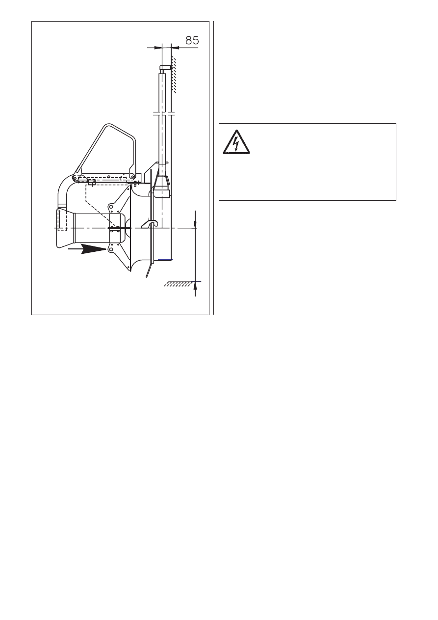
14
4630, 4640
X =
330 mm, minimum
4650, 4660
X =
500 mm, minimum
4670, 4680
X =
650 mm, minimum
Fit a hook on the lifting handle. Lift the pump so that it
slips on to the guide bars.
Lower the pump so that the inlet cone hooks into the
ring on the discharge connection.
Run the cables through tube so that they do not have
any sharp bends and are not pinched.
NOTE! The end of the cable must not be submerged.
Leads have to be above flood level, as water may
penetrate through the cable into the junction box or
the motor.
In all installations, make sure that
the motor cable cannot be drawn
into the propeller.
The cables are fragile, beware that
no sharp bends occure throughout
(during) installation procedure
especially by entrance flange.
X
Liquid flow direction
40254
15
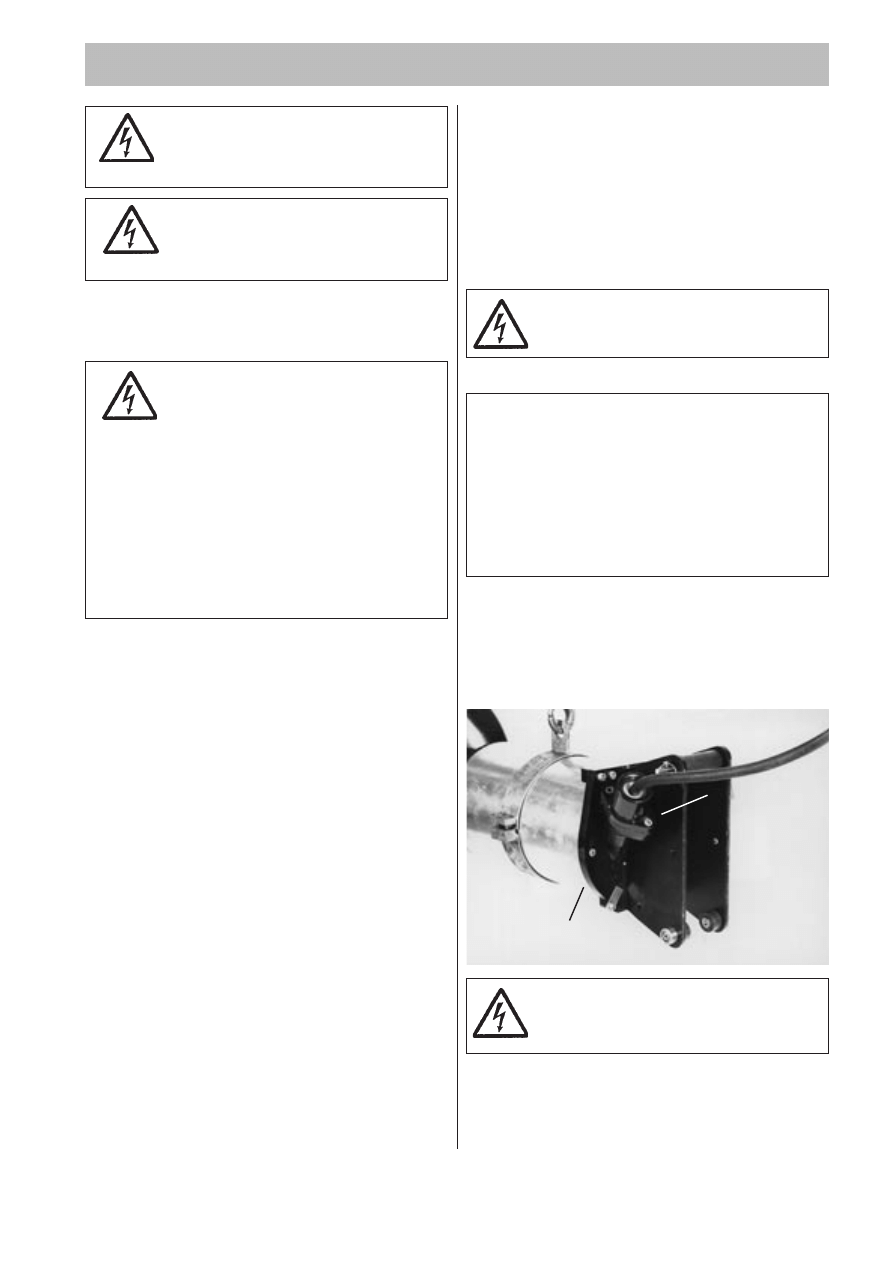
ELECTRICAL CONNECTIONS
Make sure the cable leads do not be-
come trapped between the fixing plate
and the stator casing (b).
All electrical work shall be carried out under the super-
vision of an authorized electrician.
Local codes and regulations must be observed.
Check that the voltage and frequency on the data
plate are in accordance with your actual power supply.
The motor cannot be connected for different voltages.
If intermittent operation is prescribed (see data plate),
the mixer should be provided with control equipment
that provides such operation.
Under no circumstances may the starting equipment
be installed in direct connection with the tank.
To avoid leakage into the mixer check:
— that the cable entry seal sleeve and washers con-
form to the outside diameter of the cable. See the
parts list.
— that the outer sheath on the cable is not damaged.
When refitting a cable which has been used before,
always cut off a short piece of the cable so that the
cable entry sleeve does not seal onto the cable at
the same position again.
Remember that the starting surge can be up to 3.5
times higher than the rated current. Make sure that the
fuses or circuit breakers are of the proper amperage.
The table (see “Product Description”) gives rated cur-
rent and starting current. Fuse amperage and cable
must be selected in accordance with local rules and
regulations.
The overload protection (motor protection breaker)
shall be set to the motor’s rated current as given on
the data plate.
With a clockwise phase sequence L1-L2-L3 (R-S-T), the
propeller will rotate correctly, i.e. clockwise as viewed
from the motor side. Check the phase sequence in the
main (line) using a phase sequence indicator.
Three thermal contacts are incorporated in the stator
and are normally closed. The thermal contacts can be
connected to maximum of 250 volts, breaking at 4
amps. current at maximum.
Connect the thermal contacts to the starter.
Thermal contacts must always be
used on Ex-approved machine due
to approval conditions.
Motor cable
CAUTION!
If the machine is intended for use with a
Variable frequency Drive (VFD), be careful in
choosing a motor cable. The VFD might
require a screened cable.
Please, read the manufacturer’s instruction for
the VFD.
If necessary, contact your ITT Flygt represen-
tative.
Available motor cable are SUBCAB
®
or SUBCAB
®
AWG or a chemically resistant cable type HCR.
Connect the motor cable to the terminal board as
illustrated in the figure “Direct on-line start”.
Connect the leads from the motor control circuit to T1
and T2.
▲ ▲ ▲ ▲ ▲
a
▲
▲
▲
▲
▲
b
Tighten the screws (a) so that the cable entry unit
forms an effective seal.
Connect the motor cable to the starter equipment.
Check the direction of rotation, see “Before starting”.
Ex version!
Electrical connections of the explo-
sion-proof mixer must be performed
by authorized personnel.
All electrical equipment must be
earthed (grounded). This applies to
both the machine and any control or
monitoring equipment.
Failure to heed this warning may cause a lethal
accident. Make sure that the earth lead is cor-
rectly connected by testing it.
NOTE for Ex-approved machine
All work on the explosion-proof motor section must
be performed by personnel authorized by Flygt.
Flygt disclaims all responsibility for work done
by untrained, unauthorized personnel.
Before starting work on the machine,
make sure that the machine is
isolated from the power supply and
cannot be energized.
16
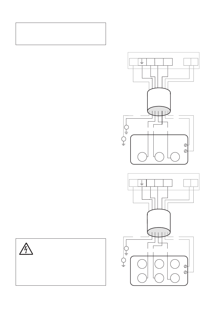
Y - Connection
4650 - 4660
CABLE
GC
GC
T1
T2
L2
L3
T1 T2
L1
GC
3~
V1
W1
T2
U1
L1
L2
L3
T1
NOTE! With long cables, the voltage drop must
be taken into consideration, since the motor’s
rated voltage is the voltage measured at the
terminal board in the machine.
Connection of the motor cable and
the stator leads
Connect the motor cble and stator leads as shown in
the wiring diagrams.
Cable
Conductors
Connection
Connection
starter
terminal board
SUBCAB
®
4Gx
Brown
L1
U1
Blue
L2
W1
Black
L3
V1
Yellow/Green
Earth
Earth
Black T1
T1*
T1*
Black T2
T2*
T2*
SUBCAB
®
xAWG/7
Red
L1
U1
White
L2
W1
Black
L3
V1
Yellow
GC**
GC**
Yellow/Green
Earth
Earth
Orange
T1*
T1*
Blue
T2*
T2*
HCR SO7E6E5-7
Black 1
L1
U1
Black 2
L2
W1
Black 3
L3
V1
Black 4
T1*
T1*
Black 5
T2*
T2*
Black 6
-
-
Yellow/Green
Earth
Earth
* Terminal for connection of termal contacts in motor and
monitoring equipment.
** GC = Ground Check
For safety reasons, the earth lead
should be longer than the phase
leads. If the motor cable is jerked
loose by mistake the earth lead
should be the last to come loose
from its terminal. This applies to both
ends of the cable.
Make sure that the mixer is
correctly earthed (grounded).
Stator leads
Stator leads
Connection
terminal board
Red
U1
Brown
V1
Yellow
W1
Y - Connection
4630 - 4640
CABLE
GC
GC
T1
T2
L2
L3
T1 T2
L1
GC
3~
V1
W1
T2
U1
L1
L2
L3
T1
Direct on line start
Direct on line start
If the direction of rotation is wrong, transpose two of
the phase leads.
17
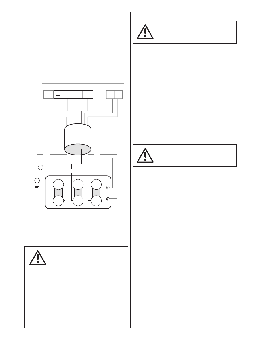
CABLE
GC
GC
T1
T2
W2
V2
U2
L2
L3
T1 T2
L1
GC
3~
D - connection
4670 - 4680
L3
L1
L2
V1
W1
T1
U1
T2
Stator leads
Stator leads
Connection
terminal board
Red
U1
Brown
V1
Yellow
W1
Green
U2
Blue
V2
Black
W2
Direct on line start
If persons are likely to come into
physical contact with the machine
or mixed/pumped media (liquid),
e.g. on farms etc, the earthed
(grounded) socket must have an additional
earth-(ground-) fault protection
device (GFI) connected.
When mixing/pumping near a lake (jetties,
beaches and ponds etc) a safety distance of at
least 20 meters (65 ft) between the person and
the machine is necessary. The machine must
never be placed directly into a swimming pool.
If used in connection with swimming pools,
special safety regulations apply.
Monitoring equipment
Make sure that the monitoring
equipment incorporated in the
product is correctly connected.
Capacitive leakage sensor CLS-30 and
leakage sensor FLS (built in version).
The machine is available with leakage sensors for
sensing water in the oil and/or the stator casing.
A plate in the junction box shows that the machine is
equipped with sensors.
CLS-30 is a leakage sensor for sensing water in the oil
casing and issues an alarm when the oil contains 30%
water. Oil change is recommended within 14 days of
alarm. If the sensor issues an alarm shortly after the oil
is changed, contact your nearest Flygt representative.
The CLS-30 sensor is installed in the bearing housing
and goes down into the oil casing. Available for 4650
to 4680. The CLS-30 sensor is not applicable to Ex-
approved machines.
Observe that the CLS cover is
made of glass and can cause
personal damage.
The FLS sensor consists of a small float switch for
sensing water in the stator casing.
The FLS sensor is installed in the bottom of the stator
casing.
The two sensors, CLS-30 and FLS, can be used in the
same machine. They are connected in parallel. Follow
the instruction for monitoring equipment.
18
Watch out for the propeller and for the
starting jerk, which can be powerful.
OPERATION
liquid is impaired, by unbalanced propellers or by air
sucked down by the propeller.
Vibration can also occur due to interference between
several mixers.
For another operating direction for the mixer, contact
ITT Flygt.
In continuous operation, air must not be drawn down
by the propeller (a vortex must not form).
NOTE! In order to avoid overheating the ma-
chine, it must always work completely sub-
merged in the liquid.
During operation of PP-pump
Test-run the pump and note the current surge during
start-up. At the instant of starting, it is normal for the
current to exceed the operating current by 10—20 %
for a few seconds. The steady-state current should be
less than the rated current.
Excessive power consumption may be caused by:
— too high head
— wrong rotation
— high viscosity or density
— clogged or badly shaped propeller
— an improperly adjusted pump
— incorrect blade angle
— changing gap between propeller and inlet cone
(due to damaged cone)
Low power might be caused by:
— vortex formation
— low head
— incorrect blade angle
— changing gap between propeller and inlet cone
(due to damaged cone)
Check that the flow is non-violent and that the pump
does not vibrate.
Vibration can occur due to:
— damaged propeller
— clogged propeller
— air suction through surface - vortex
— disturbance from other pumps, uneven attacking
flow or too high head
— changing gap between propeller and inlet cone
(due to damaged cone)
Tendency to clog can easily be observed by means of
an apere.
In continuous operation, air must not be drawn down
by the propeller (a vortex must not form).
NOTE! In order to avoid overheating the ma-
chine, it must always work completely sub-
merged in the liquid.
Check the direction of rotation. See the figure. The
propeller should rotate clockwise, as viewed from the
motor side.
The machine must be fixed to the guide bar during
test starting.
Before starting
Check that the oil level minimum reaches up to the
centrumline of the shaft.
Remove the fuses or open the circuit breaker and
check that the propeller can be rotated by hand.
Check that the cable entry is securely tightened.
Check that the monitoring equipment (if any) works.
During operation of mixer
Watch out for the propeller in rotation.
The mixer is intended to operate with or without jet
ring, due to its main application area. Operating with-
out jet ring means that strict carefulness must be ob-
served at test starting and in operation.
Test-run the mixer and note the current surge during
start-up. At the instant of starting, it is normal for the
current to exceed the operating current by 10—20 %
for a few seconds. The steady-state current should be
less than the rated current.
Excessive current consumption may be caused by
high viscosity or density of the liquid or an improperly
adjusted mixer.
Check accurately that the mixer does not vibrate.
Vibration can occur when mixing is too vigorous in a
small tank volume, or when the inflow or outflow of
19
CARE AND MAINTENANCE
Safety precautions
Before starting work on the machine,
make sure that the machine is isolat-
ed from the power supply and can-
notbe energized.
This applies to the control circuit as
well.
To prevent injury watch out for damaged and worn
parts.
NOTE! This applies to the control circuit as well.
The following points are important in connection with
work on the machine:
— make sure that the machine has been thoroughly
cleaned.
— observe good personal hygiene.
— beware of risk of infection.
— follow local safety regulations.
The mixer is designed for use in liquids which can be
hazardous to health. In order to prevent injury to the
eyes and skin, observe the following points when
working on the machine:
— Always wear goggles and rubber gloves.
— Rinse the mixer thoroughly with clean water before
starting work.
— Rinse the components in water after disassembly.
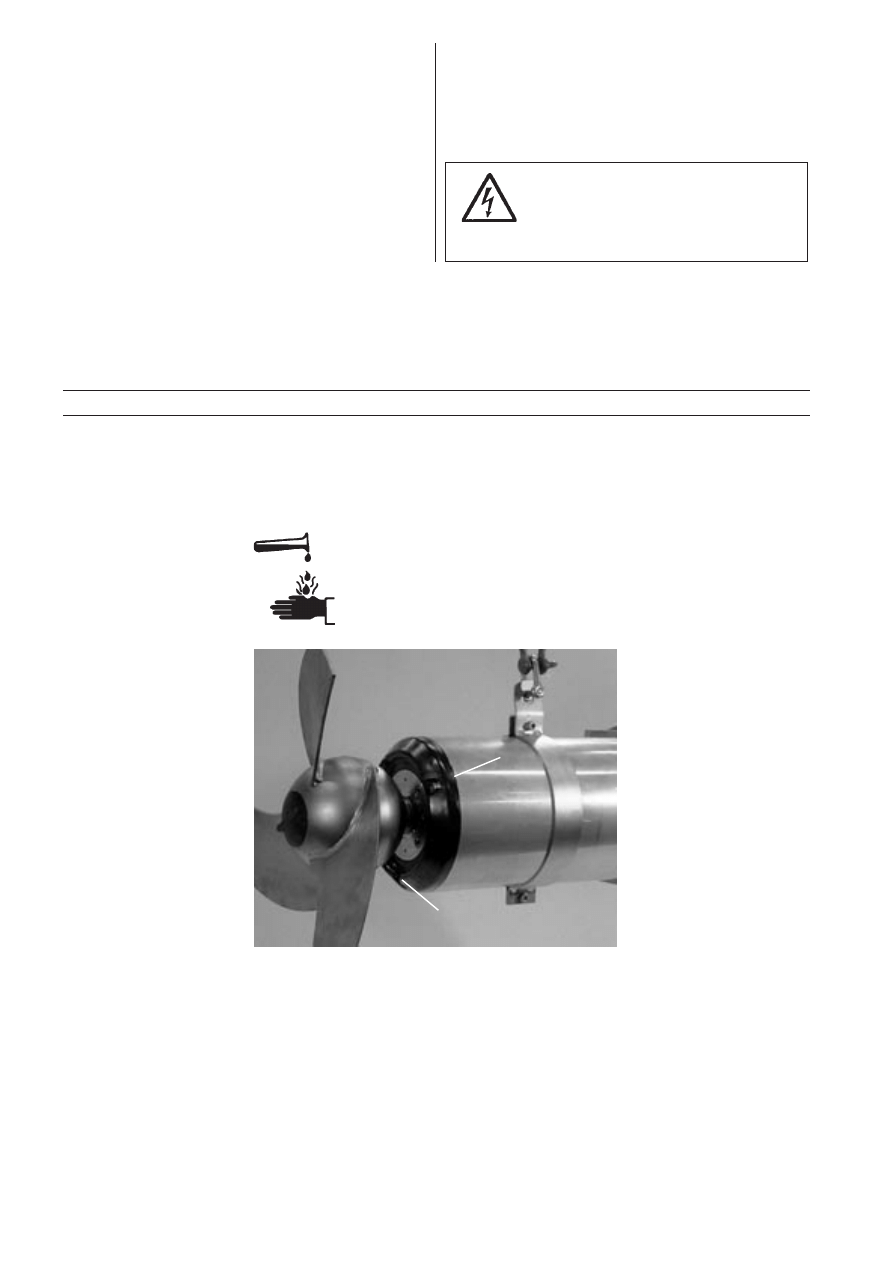
— Hold a rag over the oil casing screw (124) when
removing it. Otherwise, pressure that may have
built up in the mixer due to leakage of liquid into the
mixer may cause splatter into the eyes or onto the
skin.
Proceed as follows if you get hazardous chemicals
in your eyes:
— rinse immediately in running water for 15 minutes.
Hold your eyelids apart with your fingers.
— contact an eye doctor.
on your skin:
— remove contaminated clothes.
— wash skin with soap and water.
— seek medical attention if required.
Make sure that the machine (or parts
of the machine) can't roll or fall over
and damage people or property.
In some installations the machine
surface and the surrounding liquid
may be hot. Bear in mind the risk of
burn injures.
Ex-version!
All work on the explosion-proof
motor section must be performed
by personnel authorized by Flygt.
Service
Major overhaul of the mixer should be made in a ser-
vice workshop.
Tendency to clog can easily be observed by means of
an amperemeter.
NOTE! Check the propeller. If the propeller is hard
worn to uneven leading edge, the motor can be over-
loaded, because of clogging.
Inspection
Inspection involves that following will be checked and
measured if required;
— replacement of all worn components.
— check all screw connections.
— check quantity and condition of the oil.
— check if there is liquid in the stator casing.
— check the cable entry and condition of the cable.
— functional check of the start equipment.
— functional check of monitoring equipment.
— check of direction of rotation.
— check the lifting device and guide bars (clearance
and wear).
— check of electrical insulation.
— replace all O-rings which are removed for inspec-
tion.
— check and rinse the space around the seals. See
also “Recommended inspection”
Inspections and service intervals
Regular inspection and preventive maintenance en-
sure more reliable operation. The maintenance sched-
ule below gives the recommended period of time when
the machine should pass inspection and major overhaul.
The maintenance schedule is divided into two groups
A and B depending on wearing and temperature.
Group Wearing/Temperature
Inspection
Major
overhaul
A
• None or moderate/
Every 8000 Once every
40°C (104°F)
hours or
five years
once a
or every
year
50 000 hours
B
• None or moderate/
Every 4000 Once every
40°C - 90°C
hours or
two years or
(104°F-194°F)
twice a
every 20 000
• Heavy 40°C (104°F) year
hours or when
• Csb inner seal
inspect.
indicates.
20
Service contract
Flygt or its agent normally offers service agreements
in accordance with a preventive maintenance plan. For
further information, please contact your Flygt repre-
sentative.
Ex-approved machine!
All work on the explosion-proof
motor section must be performed by
personnel authorized by Flygt.
Oil in
▲ ▲ ▲ ▲ ▲
Oil out
▲
▲
▲
▲▲
Major overhaul
This requires special tools and should be done by an
authorized service shop. Workshop overhaul involves
in addition to the inspection, that the following will be
measured;
— replacement of bearing.
— replacement of the plug-in seal..
— replacement of oil.
— replacement of O-rings.
— replacement of seals in cable entry and moving the
entry position of the cable.
— replacement of cable.
Recommended inspections
Inspection of
Action
Visible parts on mixer
Replace or fix worn and damaged parts.
and installation
Make sure that all screws, bolts and nuts are tight.
Check the condition of lifting device/lifting eyes, chains and wire ropes.
Check that the guide bar is vertical.
Replace worn parts if they impair function.
Oil quantity
WARNING. If the seal leaks, the oil casing may be under
pressure. Hold a rag over the oil casing screw in order to prevent
splatter. See “Safety precautions” for additional information.
Check that the oil level minimum reaches up to the centrumline of the shaft.
A check of the condition of the oil can show whether there has been an increased
leakage. Check the oil by removing the oil drainage screw. Leave the oil filling
screw in place in order to restrict the flow. As the oil separates the water, the liquid
coming out first will indicate a possible leakage. Tap until clear oil is coming out.
If leakage less than 0.1 ml/h, the seal functions normally. Refill the tapped volume
with new oil. See “Changing the oil”.
If the leakage is more than 0.1 ml/h, refill the oil. Run the mixer for one week and
check the oil again. If leakage is more than 0.1 ml/h the fault may be:
— that the outer mechanical seal is damaged. Contact a Flygt service shop.
21
Inspection of
Action
Cable entry
Make sure that the cable entry is tight.
If the cable entry leaks:
— check that the entry is tightened and forms an effective seal.
— cut a piece of the cable off so that the seal sleeves seals onto a new
position on the cable.
— replace the seal sleeves.
— check that the gasket, seal sleeves and the washers, conform to the outside
diameter of the cable.
Cable
Replace the cable if the outer sheath is damaged.
Make sure that the cables do not have any sharp bends and are not pinched.
Starter equipment
If the starter equipment is faulty, contact an electrician.
Monitoring equipment
Follow the instructions for monitoring equipment.
(should be checked often)
Check:
— signals and tripping function.
— that relays, lamps, fuses and connections are intact.
Replace defective equipment.
Rotation direction of
Transpose two phase leads if the propeller does not rotate clockwise as viewed
mixer (requires voltage)
from the motor side. Rotation in the wrong direction reduces the capacity of the
mixer and the motor may be overloaded. Check the direction of rotation every
time the mixer is reconnected.
Insulation resistance
Use insulation tester. With a 1000 V-DC megger the insulation between the
phases
in the stator
and between any phase and earth (ground) should not be less than 1 M
Ω
.
Liquid in the stator casing
WARNING. If there has been leakage, the stator casing may be under pressure.
Hold a rag over the inspection screw to prevent splatter. See “Safety precautions”
for additional information.
Only Ex-approved machines; remove the screw and the angle bracket.
Remove the counter socket screw marked “INSP” and the O-ring. Remove the
inspection plug and the O-ring. Be careful not to damage the O-ring.
Tilt the machine so that any liquid in the stator casing can run out through the hole.
If there is liquid in the stator casing:
— check that the inspection plug is sufficiently tight.
— check if the cable entry is leaking.
— check if there is water in oil.
Check stator inspection plug again after one week. If the stator casing contains
liquid again, the fault may be:
— that the inner seal is damaged.
Contact a Flygt service shop.
Inspection
▲ ▲ ▲ ▲▲
▲ ▲ ▲ ▲▲
22
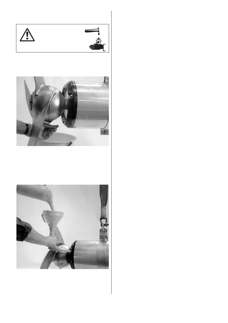
Changing the oil
Oil drainage
Unscrew the oil draining screw.
It is easier to drain the oil if the oil filling hole screw is
also removed.
Hold the mixer over a vessel and allow the oil to run out.
Put the oil casing screw back.
The oil casing may be
under pressure.
Hold a rag over the oil
plug to prevent splatter.
Lay the mixer over two supports or suspend the mixer
horizontally from an overhead crane.
Keep a container underneath the screw to catch the
oil when the screw is removed.
Oil refill
Recommended oil quantities for mixers positioned at
0° to ± 20° from the horizontal axis:
4630, 4640
0.35 litres
4650, 4660
1.0 litres
4670, 4680
2.4 litres
If the mixer will be positioned –90° downwards the
recommended oil volume must be increased to:
4630, 4640
0.55 litres
4650, 4660
1.5 litres
4670, 4680
3.8 litres
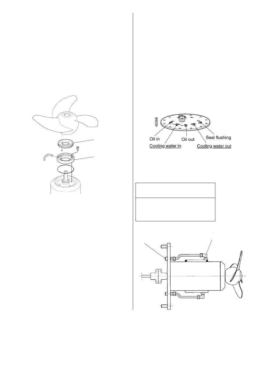
Flange mounted mixer
If the mixer is equipped with external oil change, pipes
and couplings are connected between the oil casing
and the fixing plate.
The fixing plate is provided with five threaded holes
ISO G-3/8 for inspection and change of oil, cooling
water and seal flushing.
For easy handling, equip the oil inspection holes with
hydraulic couplings. Connect the male couplings to
Oil
in and Oil out. Drain the oil into an oil vessel.
Connect an oil gun to
Oil out hydraulic coupling. Pump
the oil until oil comes out from
Oil in hydraulic cou-
pling. Disconnect the male couplings from
Oil out and
Oil in. Put back the oil plugs.
The machine is delivered from factory with a tasteless
and odourless paraffin oil suitable for raw or clean-
water applications.
This oil is authorized according to FDA 172.878, (FDA
= Food and Drug Administration authority in US).
We recommended that Mobil Whiterex or Shell Ondi-
na, with viscosity class ISO VG15 to 32, be used.
In media where paraffin oil is not required, a mineral
oil, i.e. compressor oil or hydraulic oil with (the same)
viscosity class VG15 to 32, should be used. Regular
motor oil, e.g. SAE 5(W) up to SAE 25(W) can also be
used.
Fill up with new oil in the oil filling hole, the mixer
should be in a horizontal position. Always replace the
O-rings (24) of the oil hole screws. Put the screws
back and tighten them. Tightening torque 10—20 Nm
(7.4—15 ft lb).
23
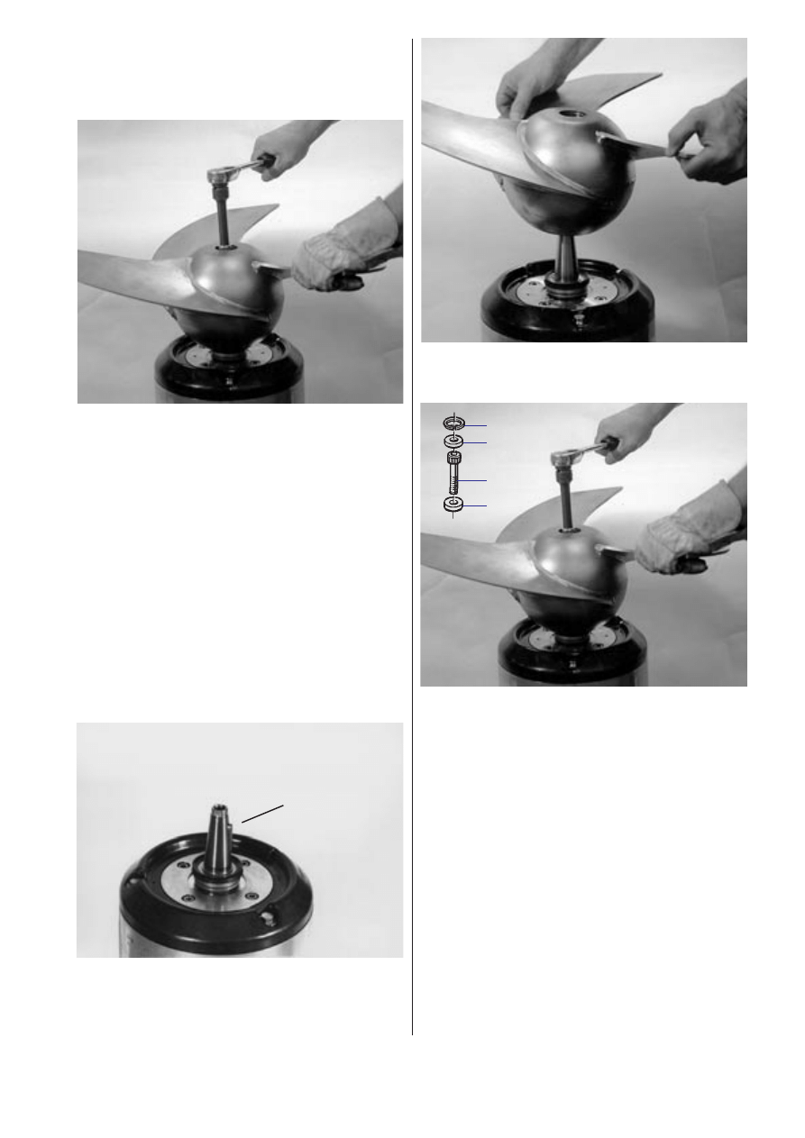
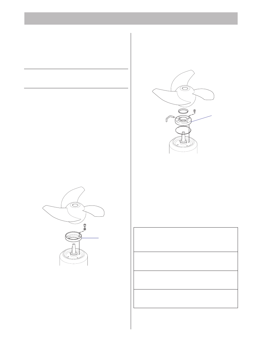
Remove the protective cover and the O-ring.
Insert an M8 Allen key into the hub screw and loosen
the propeller screw.
When the screw has been unthreaded, puller opera-
tion is obtained through the head of the screw press-
ing the propeller outwards.
Lift off the propeller.
Installing the propeller
NOTE! If the machine will be equipped with flush
protection and/or cutting rings, this must be installed
before the propeller.
Make sure that the end of the shaft is clean and free
of burrs. Polish off any flaws with fine emery cloth.
Grease the end of the shaft and the propeller hub.
Lift the propeller onto the shaft.
▲ ▲ ▲ ▲ ▲
Replacing the propeller
Removing the propeller
WARNING! A worn propeller often has very sharp
edges.
If the washers and propeller screw already are assem-
bled, all you need to do is tighten the propeller screw.
If not, place the washer (a) onto the propeller screw
(b). Fit the propeller screw. Mount the other washer (c)
and secured it by a circlip (d).
Tightening torque for:
4630, 4640
40 Nm
(30 ft lb)
4650, 4660
136 Nm (100 ft lb)
4670, 4680
197 Nm (145 ft lb)
Fit the O-ring and mount the protect cover.
Check that the propeller can be rotated by hand.
Check:
— that the parallel key is seated in the key way on the
shaft.
— that the seal ring is correctly positioned.
d
c
b
a
24
Lifting device and jet ring
Tightening torque for all the socket head screws are
for 4630–4640 22 Nm (16 ft lb) and for 4650–4680
44 Nm (33 ft lb). Screw threads shall be lubricated
with grease (90 18 00) before assembly.
(M8 = 22 Nm, M10 = 44 Nm).
Tighten the screws alternately.
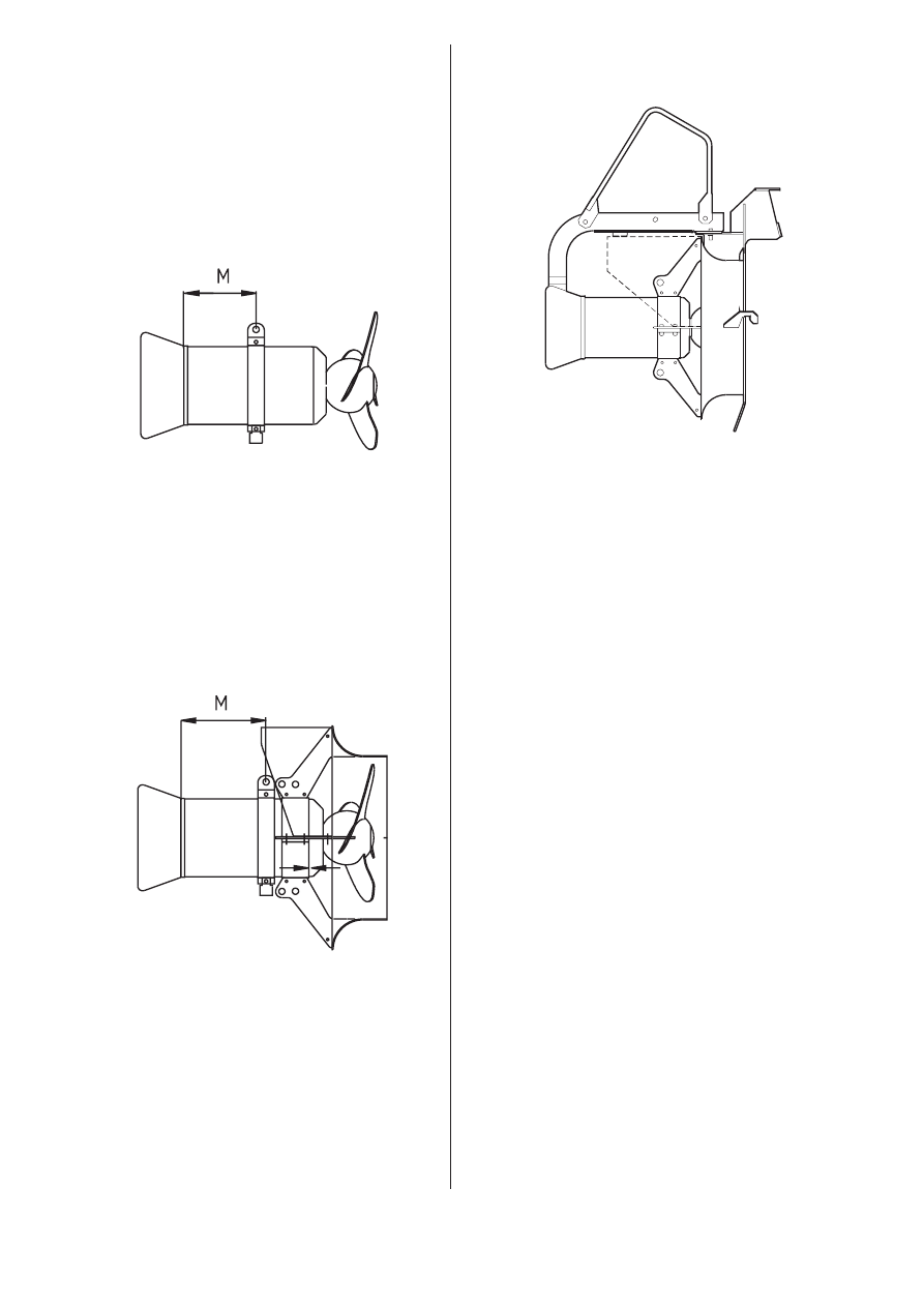
Lifting device with or without support
M = see Dimension drawings.
Lifting device and jet ring with or without support
Mount the jet ring in line with the oil casing face.
Check clearance between propeller and ring. (Rotate
the propeller by hand.)
40278
40277
M = see Dimension drawings.
40283
Lifting device and inlet cone for PP-pump
Check clearance between propeller and inlet cone.
(Rotate the propeller by hand.)
25
Tools
Besides standard tools, the following tools are re-
quired in order to perform the necessary care and
maintenance of the mixer:
Part No.
Description
84 15 66
Torque wrench 0—137 Nm (0—101 ft lb)
84 15 64
Torque wrench 50—225 Nm (37—166 ft lb)
For further information on tools, see Flygt’s Tool
Catalogue.
TOOLS AND ACCESSORIES
Start and control equipment
Flygt has suitable starting and control equipment for
the mixer. Contact Flygt for further information.
Flush protection
Installing of flushing device
NOTE. Install the flushing device before the propeller.
Mount the tube in the cover.
Fit the O-ring and the seal ring.
Flushing media/volume
The flush protected propeller hub can be flushed with
air, water or other suitable media.
Recommended minimum/maximum flow for
continuous flushing is:
Flow media
Flow
l/min
min.
max.
4630,4640
Water
0.5
—
Air
10
20
4650,4660
Water
0.8
—
Air
30
60
4670,4680
Water
1
—
Air
50
100
It is important for the result to keep the minimum flow.
Use a flow regulator.
For more information please contact Flygt.
Mount the unit.
Tighten the screws. Tightening torque 6—8 Nm.
Connect a hose, an armoured hose size 1/4" is recom-
mended for flushing.
Fit the protective ring with the 4 washers and screws.
Tightening torque 6—8 Nm.
The protecting ring must not be used in liquid with
temperature exceeding 40°C (105°F).
Seal protection
40349
Protection ring
40233
Cover
26
Cooling jacket
The machine can be equipped with cooling jacket.
Pipes and couplings are connected between the cool-
ing jacket and the fixing plate. Cooling water is acces-
sible at the fixing plate.
The fixing plate is provided with five threaded holes
ISO G-3/8 for inspection and change of oil, cooling
water and seal flushing.
For easy handling, the cooling water holes can be
equipped with hydraulic couplings or couplings with
hose clips.
After propeller and jet ring removal, the cooling jacket
is assembled by pushing it from the mixers’ propeller
side on the stator housing. To make it easy, soap
water can be used.
Recommended flow for the cooling water is shown in
the table below. Cooling water temperature 20°C
(68°F).
Mixer size
Flow
l/min
4630, 4640
2
4650, 4660
6
4670, 4680
10
Cutting rings
Assembling of cutting rings
Center the rotatary cutting ring over the propeller hub.
Use the cutting ring as a jig and drill 4 or 8 holes Ø 4.9
mm, for the rivets.
Fix the cutting ring with the rivets.
If the machine will work with seal flushing, fit the tube
in the stationary cutting ring.
Assemble O-ring, stationary cutting ring and fix the
ring with the 4 screws.
Tightening torque 6—8 Nm.
40299
Rotary
cutting
ring
Stationary
cutting
ring
Cooling jacket
Cooling
water hole
27
A universal instrument (VOM), a test lamp (continuity
tester) and a wiring diagram are required in order to
carry out fault tracing on the electrical equipment.
Fault tracing should be done with the power supply
disconnected and locked off, except for those checks
which cannot be performed without voltage.
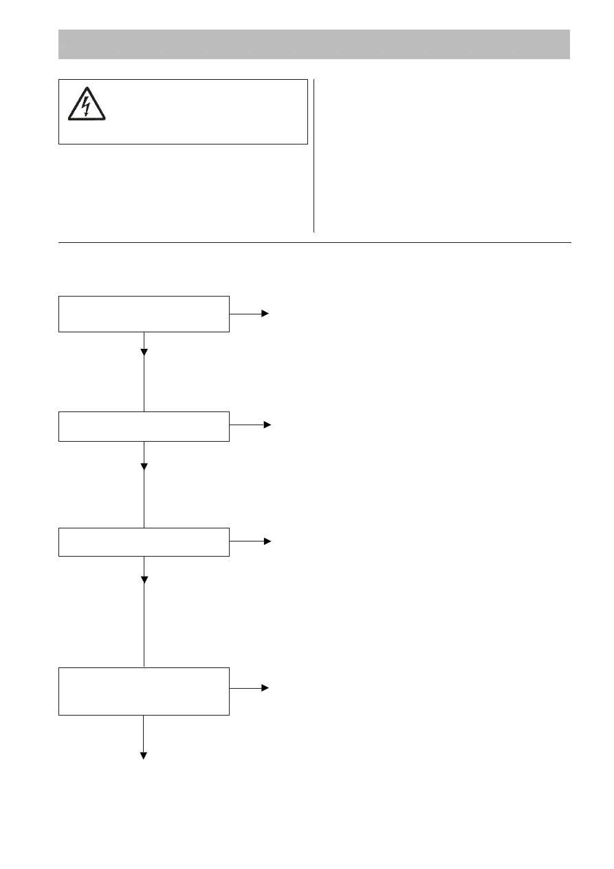
Fault Tracing (Troubleshooting)
Is an alarm signal indicated
on the control panel?
No
Can the machine be started
manually?
No
Is the installation receiving voltage?
Yes
Is the propeller stuck?
WARNING: Disconnect power
before checking the propeller.
No
Ex-approved machine!
All work on the explosion-proof
motor section must be performed by
personnel authorized by Flygt.
1. The machine fails to start
Yes
Check the cause:
— If the stator temperature is high, check that the propeller
rotates easily.
— If there is a fault in the thermal switches, contact a Flygt
service shop.
Check that the overload protection is reset.
Yes
Fault in control equipment.
Check:
— that all connections are intact.
— relay and contactor coils.
— that the control switch “Man/Auto” makes contact in both
positions.
No
Check:
— that the main power switch is on.
— that there is control voltage to the starter equipment and that
its fuses are intact.
— that there is voltage in each phase of the supply line.
— that all fuses have continuity and are tight.
— that the overload protection is reset.
— that there is no break in the motor cable.
Yes
Clean
Contact Flygt service shop.
Always make sure that there is no one near the
machine when the power supply is turned on.
Use the following checklist as an aid to fault tracing. It
is assumed that the mixer and installation have for-
merly functioned satisfactorily.
Electrical work must be performed by an authorized
electrician.
Follow local safety regulations and observe recom-
mended safety precautions.
28
2. The machine starts but motor protection trips
Yes
Adjust.
Yes
Clean the propeller.
Check that correct propeller size is assembled.
If anything else is wrong, contact Flygt service shop.
No
Check the fuses.
Notify an electrician.
Yes
Check if applicable capacitors, contact Flygt service shop.
No
Contact Flygt service shop.
Yes
Contact Flygt service shop.
Yes
Contact Flygt.
Change to a propeller with a lower pitch.
Change to a more suitable mixer.
Yes
Replace the overload protection.
Contact Flygt service shop.
* only for PP-pump
Is the motor protection set too low?
(Check with data plate)
No
Is the propeller difficult to
rotate by hand?
WARNING: Disconnect power
before checking the propeller
No
Is the installation receiving full
voltage on all three phases?
Yes
Are the phase currents uneven
or too high?
No
Is r/min according to data plate
and specification?
Yes
Is the density of the liquid too high?
No
*Is the pumping head too high or are
the loses over checkvalve too high?
No
Fault on overload protection?
No

29
Does the contactor’s selfholding
function break?
No
3. The machine starts-stops-starts in rapid sequence
Yes
Check:
— contactor connections.
— the voltage in the control circuit in relation to the rated
voltage on the coil.
Contact Flygt service shop.
Do not override the motor protection repeatedly if it has tripped.

30
SERVICE LOG
Most recent
Mixer or Pump No.
Hours of
Remarks
Sign.
service date
operation

31

www.flygt.com
4630–4680.01.08. Eng. 3M. 02.02 © ITT FLYGT AB Printed in Sweden KT 220073
892344

Certificate Number: 03-HS389435/1-PDA
This Confirmation of Product Type Approval is valid only as
of 06/OCT/2008 for the below listed product.
Please refer to the "Service Restrictions" shown below to determine if Unit Certification is required for this product.
This is to certify that, pursuant to the Rules of American Bureau of Shipping (ABS), on 06/OCT/2008 the
manufacturer of the below listed product held a valid Manufacturing Assessment (MA) and a valid Product Design
Assessment (PDA) for the below listed product, entitling the product to type approval.
The validity of the Manufacturing Assessment is dependent on satisfactory audits as required by the Rules.
The Product Design Assessment is valid only for products intended for use on ABS classed vessels, MODUs or
facilities which are in existence or under contract for construction on the date of the ABS Rules used to evaluate
the Product. For Date of ABS Rules used for evaluation; Please refer to the ABS Rules below. ABS makes no
representations regarding type approval of the Product for use on vessels, MODUs or facilities built after the date of
the ABS Rules used for evaluation.
Due to wide variety of specifications used in the products ABS has evaluated for Type Approval, it is part of our
contract that; whether the standard is an ABS Rule or a non-ABS Rule, the Client has full responsibility for
continued compliance with the standard.
ITT WATER AND WASTEWATER AB
Model Name(s): Series 4600
Presented to:
ITT WATER AND WASTEWATER AB
.
EMMABODA
S-361 80
Sweden
Intended Service:
Offshore Applications
Description:
The 4600 Series, three bladed propeller, shroud assembly, submersible mixers are
available in three versions: Cast iron with stainless steel skin; 316 stainless steel;
Exotic stainless steel per ASTM S 31253 (ProAcid) 254.
Ratings:
Series 4600 Mixers are comprised of the following: 3 phase, submersible squirrel
cage induction motor with thermal protection in the stator set at 125 °C; Motor
voltage: 208/230/460/575 V; Ambient temperature from 40 °C to 90 °C; Class 1,
Division 1, Groups C & D, Class II, Division 1, Groups E, F, & G, Class III, Division
1. For details see attached 'pdf'
Service Restrictions:
Unit Certification is not required for this product. If the manufacturer or purchaser
request an ABS Certificate for compliance with a specification or standard, the
specification or standard, including inspection standards and tolerances, must be
clearly defined.
Comments:
Duplicate PDA resides with ITT Water and Wastewater USA (Flgyt Products). The
Type Approval is applicable only to those devices bearing the CSA and / or FM
Listing Mark. Explosion Proof Version - equipment data as for standard version
above: Model No. 4630.490; 4660.490; 4640.490; 4670.490; 4650.490; 4680.490
Notes / Documentation:
This Product Design Assessment (PDA) is valid only for products intended for use
on ABS classed vessels, MODUs or facilities which are in existence or under
10/06/2008 9:45:35 AM
Copyright 2001 American Bureau of Shipping. All rights reserved.
Page 1 of 2

contract for construction on the date of the ABS Rules used to evaluate the
Product.
Term of Validity:
This Design Assessment Certificate number 03-HS389435/1-PDA, dated
23/Sep/2008 will expire on 22/Sep/2013 or at an earlier date should there be
alterations to the product's design or changes to the referenced ABS Rules and
other specifications, which affect the product. Product use on or after 1 January
2009, will be subject to compliance with the ABS Rules or specifications in effect
when the vessel, MODU or facility is contracted. The product's acceptability on
board ABS-classed vessels or facilities is defined in the service restrictions of this
certificate.
ABS Rules:
2008 Steel Vessels Rules 1-1-4/7.7, 4-8-3/1.11, 4-8-4/1.5, 4-8-4/27; 2008 MODU
Rules 4-3-3/9.1.2, 4-3-3/3.1.1; 2000 Guide for Building & Classing Facilities on
Offshore Installations 3-6/15.3.
National Standards:
API RP 14F 2008 Section 2; CSA C22.2 No. 108-M89778 & 49-1981; UL Standard
for Safety # 778; FM File 1WuA1.AE & 1B8A2.AE
International Standards:
Government Authority:
EUMED:
Others:
ISO 9001:2000
Manager, ABS Programs
ABS has used due diligence in the preparation of this certificate and it represents the information on the product in the ABS Records as of the
date and time the certificate was printed. Type Approval requires Drawing Assessment, Prototype Testing and assessment of the
manufacturer's quality assurance and quality control arrangements. Limited circumstances may allow only Prototype Testing to satisfy Type
Approval. The approvals of Drawings and Products remain valid as long as the ABS Rule, to which they were assessed, remains valid. ABS
cautions manufacturers to review and maintain compliance with all other specifications to which the product may have been assessed. Further,
unless it is specifically indicated in the description of the product; Type Approval does not necessarily waive witnessed inspection or survey
procedures (where otherwise required) for products to be used in a vessel, MODU or facility intended to be ABS classed or that is presently in
class with ABS. Questions regarding the validity of ABS Rules or the need for supplemental testing or inspection of such products should, in all
cases, be addressed to ABS.
Certificate Number: 03-HS389435/1-PDA
10/06/2008 9:45:35 AM
Copyright 2001 American Bureau of Shipping. All rights reserved.
Page 2 of 2
Document Outline
Wyszukiwarka
Podobne podstrony:
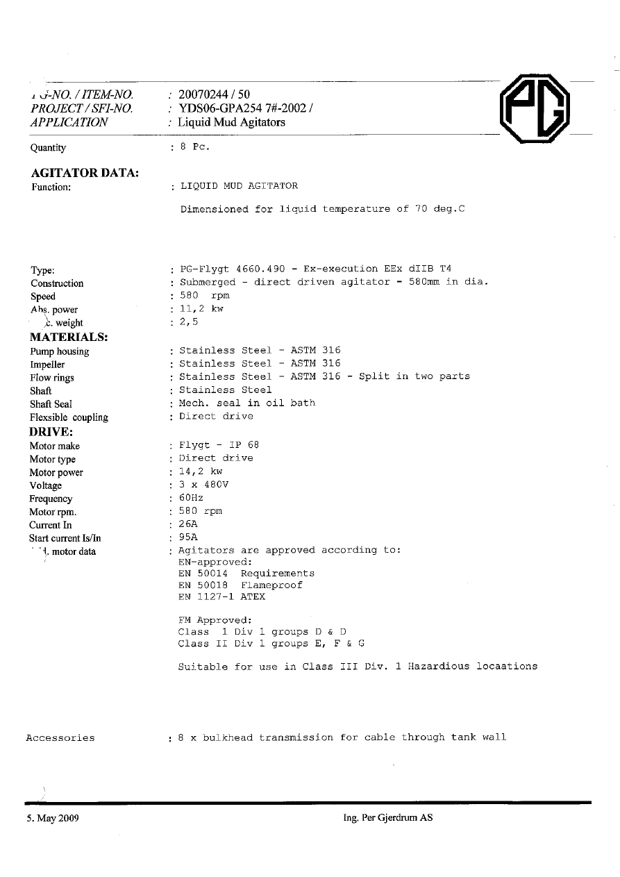
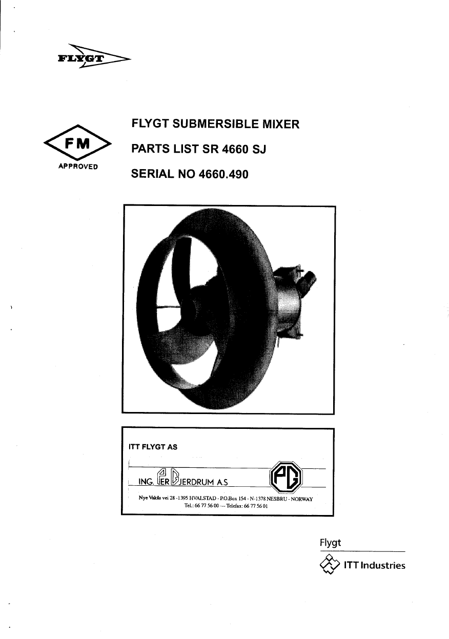
LIQUID MUD AGITATORS
Mississippi Mud
liquid membranes
liquid liquid separator operating principle
Ionic liquids as solvents for polymerization processes Progress and challenges Progress in Polymer
Liquid Phase Sintering tekst
Ionic liquids solvent propert Journal of Physical Organic Che
skład chemia RED CITRUS DISHWASHING LIQUID
skład chemia WHITE LAUNDRY LIQUID
Density and viscosity of several pure and water saturated ionic liquids Green Chemistry
skład chemia ALOE DISHWASHING LIQUID
LIQUID NITRIDING
Liquid Cocaine
Beigbeder ?rniere inventaire avant liquidation
Lab12 13spr, PWr, III semestr, MUD
Ionic Liquids, Polymerization in
Ferroelectric Liquid Crystalline Elastomers
MUD PUMP 2
więcej podobnych podstron