
575
In This Chapter
20
Combining Parts and
Surfaces
In Autodesk
®
Mechanical Desktop
®
, surfaces are
valuable features because they can represent complex
curved shapes. When joined to a parametric part, they
cut away an angular surface and replace it with a
sculpted face. A surface may also add material to a part
as a protrusion. In this tutorial, you combine parametric
and surface modeling by creating a camera body with a
sculpted face.
■
Creating a part with multiple
features
■
Creating a simple surface
■
Attaching a surface
parametrically to a part
■
Cutting out features
■
Creating mounting holes
■
Sketching on work planes
■
Revising and finishing a design

576
|
Chapter 20
Combining Parts and Surfaces
Key Terms
Term
Definition
base surface
A basic underlying surface that carries a shape across a larger area. Can be trimmed
to precise shapes as needed, but the base surface remains intact and may be
displayed.
model view
Changes orientation of the viewer so that the object is viewed from a different
position. Individual views can be displayed in multiple viewports. For example, enter
3 at the Command prompt to create three viewports with default views: top, front,
and right isometric.
NURBS
Acronym for nonuniform rational B-spline. The SPLINE command creates a true
NURBS curve and can be used to create a surface.
rail
One or more curved lines along which surfaces are swept. They form the curvature of
a swept surface.
spline
A curved line defined by specified control points that assumes a unique shape. Used
to create curved surfaces. The radius of a spline curve is constantly changing. Splines
are used as the basis of free-form surfaces.
surface cut
A feature created when a surface is joined to a part. Where the surface cuts the part
or protrudes, the part face assumes the curved shape of the surface. The surface, like
other features, is parametric; both the surface and the part retain their parametric
relationship whenever either is modified.
wire
A generic term referring to lines, arcs, circles, ellipses, 2D and 3D polylines,
augmented lines, and splines.
work plane
An infinite plane attached to a part. Can be designated as a sketch plane and can be
included in a constraint or dimension scheme. Work planes can be either parametric,
or non-parametric.
work point
A parametric work feature used to position a hole, the center of a pattern, or any
other point for which there is no other geometric reference.
Basic Concepts of Combining Parts and Surfaces
|
577
Basic Concepts of Combining Parts and
Surfaces
You can use Mechanical Desktop
®
to create angular-shaped parts. You can
apply 3D surfaces to those parts to create hybrid parts consisting of a mixture
of angular and curved shapes. With Mechanical Desktop you can create
model designs with shapes of varying types.
You can apply surfaces to Mechanical Desktop parts and use those surfaces to
cut material from a parametric part, to create any hybrid shapes that your
design requires.
You can also use surfaces to add material to angular parts.
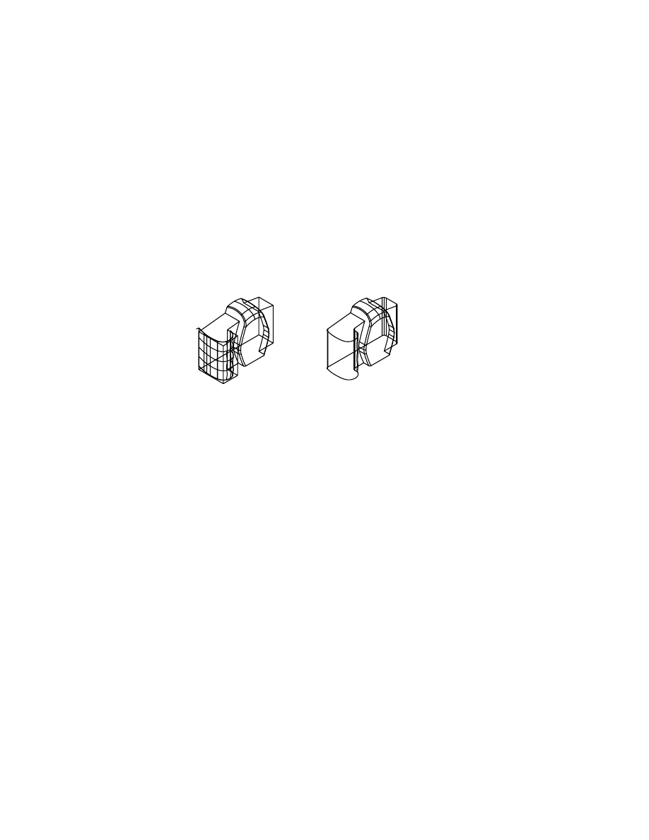
Using Surface Features
A feature created from surfaces has the shape of a contoured surface. You
either cut away material or add material as a protrusion to join it to a part.
In this tutorial, you cut away an angular face and replace it with a sculpted
surface.
Surfaces must have these characteristics to be used as features on models:
■
A contoured surface must have four logical boundaries.
■
The curved shape must be a single surface. If you need multiple surfaces
to represent the shape, you must join them into a single surface.
■
The surface must be a nontrimmed base surface. Join only base surfaces,
not interior trim edges of trimmed surfaces.
■
The surface must extend past the part on all four sides.
■
A surface cannot contain sharp corners.
■
Surfaces should have a minimum number of internal patches. These sur-
faces work better and faster than complex ones.
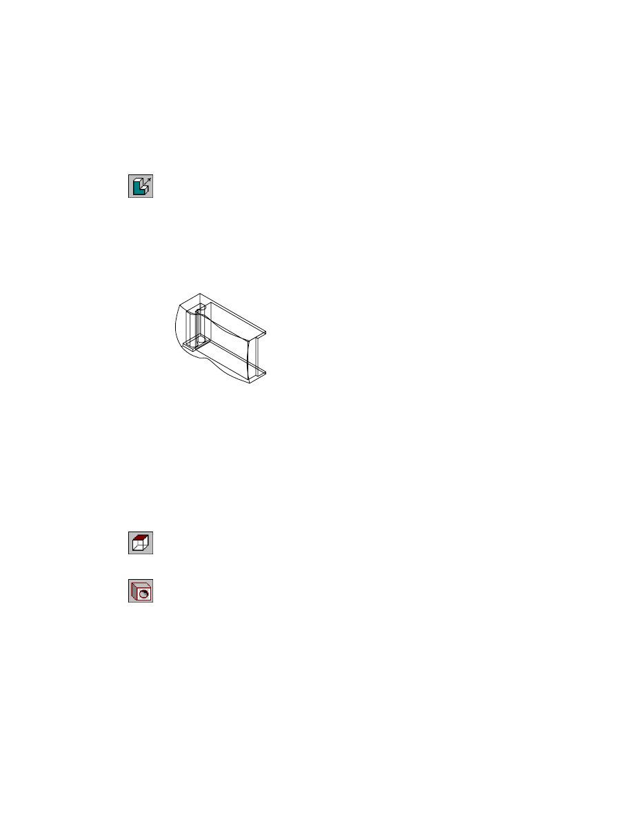
before surface cut
after surface cut
578
|
Chapter 20
Combining Parts and Surfaces
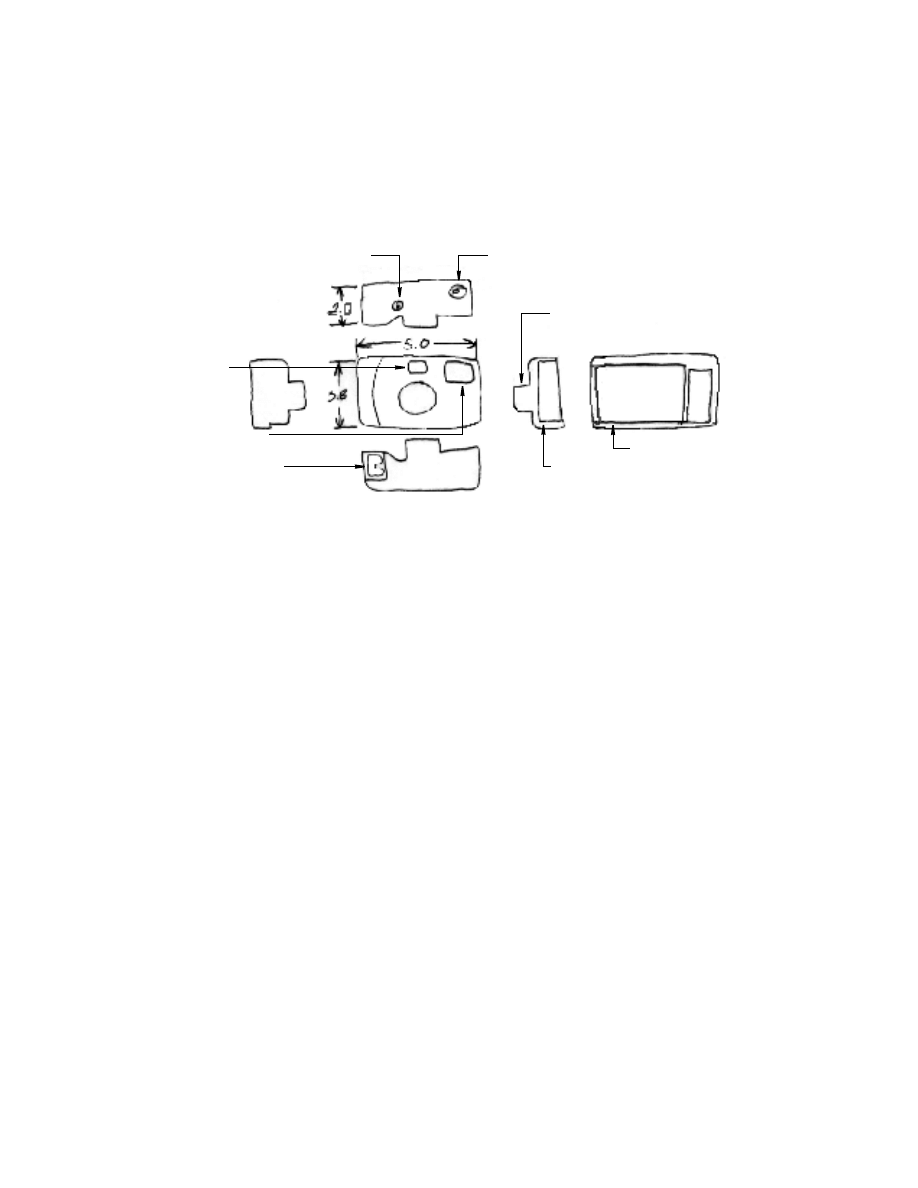
First, sketch the camera from all sides (top, side, front, and isometric views).
With a complete idea, you can decide where to place features on the camera
body.
The camera body, which is common to all other features, is the base feature.
The camera design has many other features, some of which are cutaways
from the body: battery and film compartments and cutouts for their doors;
mounting holes for the film advance and shutter release; and compartments
for the viewfinder and the flash. The lens sheath feature, a sculpted surface,
is joined to the camera face.
battery compartment
shutter release mount
film advance mount
film compartment
viewfinder
compartment
flash compartment
lens sheath
door cutout
Creating Surface Features
|
579
Creating Surface Features
Open the file camera.dwg in the desktop\tutorial folder. The file contains the
settings you need, and the geometry to create the camera body—an extruded
feature and some NURBS curves. You use NURBS to create the surface for the
sculpted camera face.
NOTE
Back up the tutorial drawing files so you still have the original files if you
make a mistake. See “Backing up Tutorial Drawing Files” on page 40.
You can work on your model in any viewport, moving among views as you
create features.
First, you create two surfaces by sweeping wires along a rail. Then, you join
them into a single surface and extend the surface so that it covers the camera
body.
NOTE
If you prefer to use toolbuttons to access commands, choose Surface ➤
Launch Toolbar.
580
|
Chapter 20
Combining Parts and Surfaces
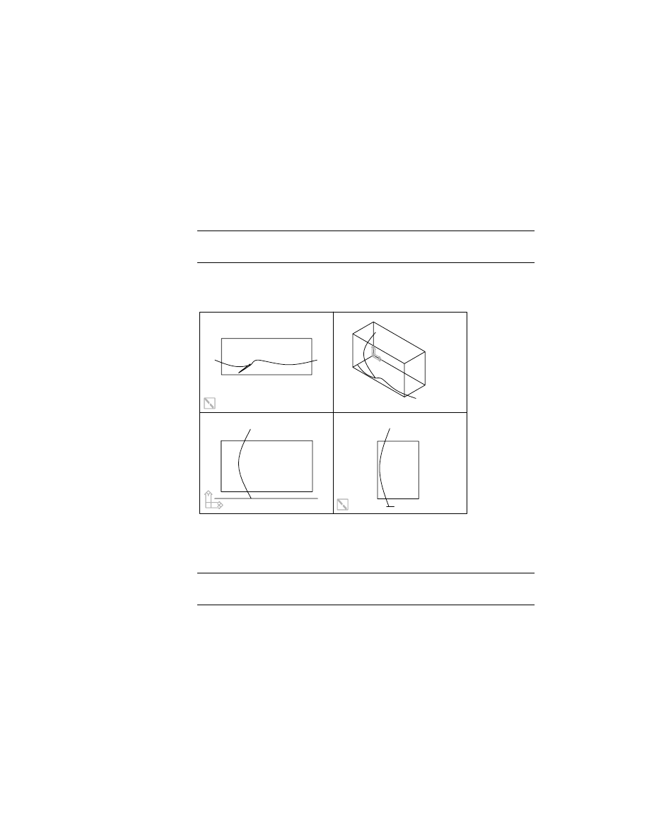
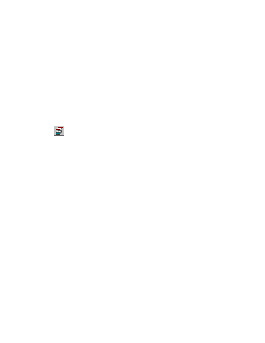
To create a swept surface
1
Use
AMSWEEPSF
to sweep a spline along a rail, responding to the prompts.
Desktop Menu
Surface ➤ Create Surface ➤ Sweep
Select cross sections:
In the front view, choose the right horizontal spline (1)
Select cross sections:
Press
ENTER
Select rails:
Select the vertical spline (2)
Select rails:
Press
ENTER
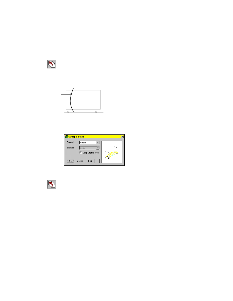
2
In the Sweep Surface dialog box, specify:
Orientation:
Parallel
Choose OK. The first half of the swept surface is created.
3
Create the second half of the swept surface, responding to the prompts.
Desktop Menu
Surface ➤ Create Surface ➤ Sweep
Select cross sections:
Select the left horizontal spline (3)
Select cross sections:
Press
ENTER
Select rails:
Select the vertical spline (2)
Enter an option [Next/Accept] <Accept>:
Press
ENTER
Select rails:
Press
ENTER
In the Sweep Surface dialog box, specify:
Orientation:
Parallel
Choose OK.
2
3
1

Creating Surface Features
|
581
4
Use
AMJOINSF
to join the two surfaces, responding to the prompts.
Desktop Menu
Surface ➤ Edit Surface ➤ Join
Select surfaces to join:
Select the right surface (1)
Select surfaces to join:
Select the left surface (2) and press
ENTER
The two surfaces create a single surface. The resulting surface probably does
not extend beyond the part on all sides, so you need to lengthen the surface.
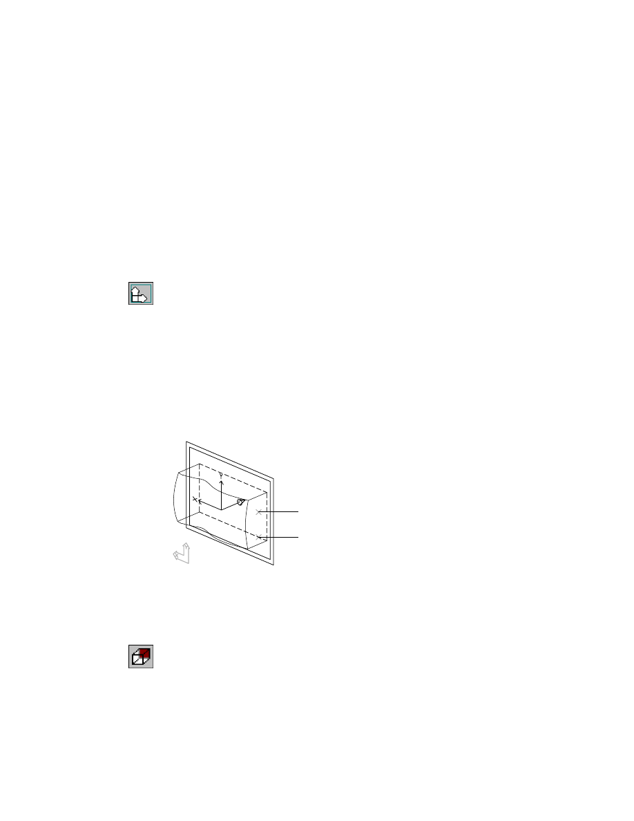
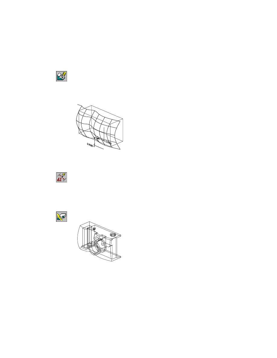
5
Use
AMLENGTHEN
to lengthen the surface, responding to the prompts.
Desktop Menu
Surface ➤ Edit Surface ➤ Lengthen
Base edge=Single Extension=Percent Method=Parabolic Value=110.0000%
Select surface edge or spline [eDge/Extend/Keep/Mode/Value]:
Enter v
Enter percent <110.0000%>:
Enter 105
Base edge=Single Extension=Percent Method=Parabolic Value=105.0000%
Select surface edge or spline [eDge/Extend/Keep/Mode/Value]:
Select the rightmost vertical edge of the surface (1)
Base edge=Single Extension=Percent Method=Parabolic Value=105.0000%
Select surface edge or spline [eDge/Extend/Keep/Mode/Value]:
Press
ENTER
The surface now extends past the cube representing the camera body.
1
2
1
582
|
Chapter 20
Combining Parts and Surfaces
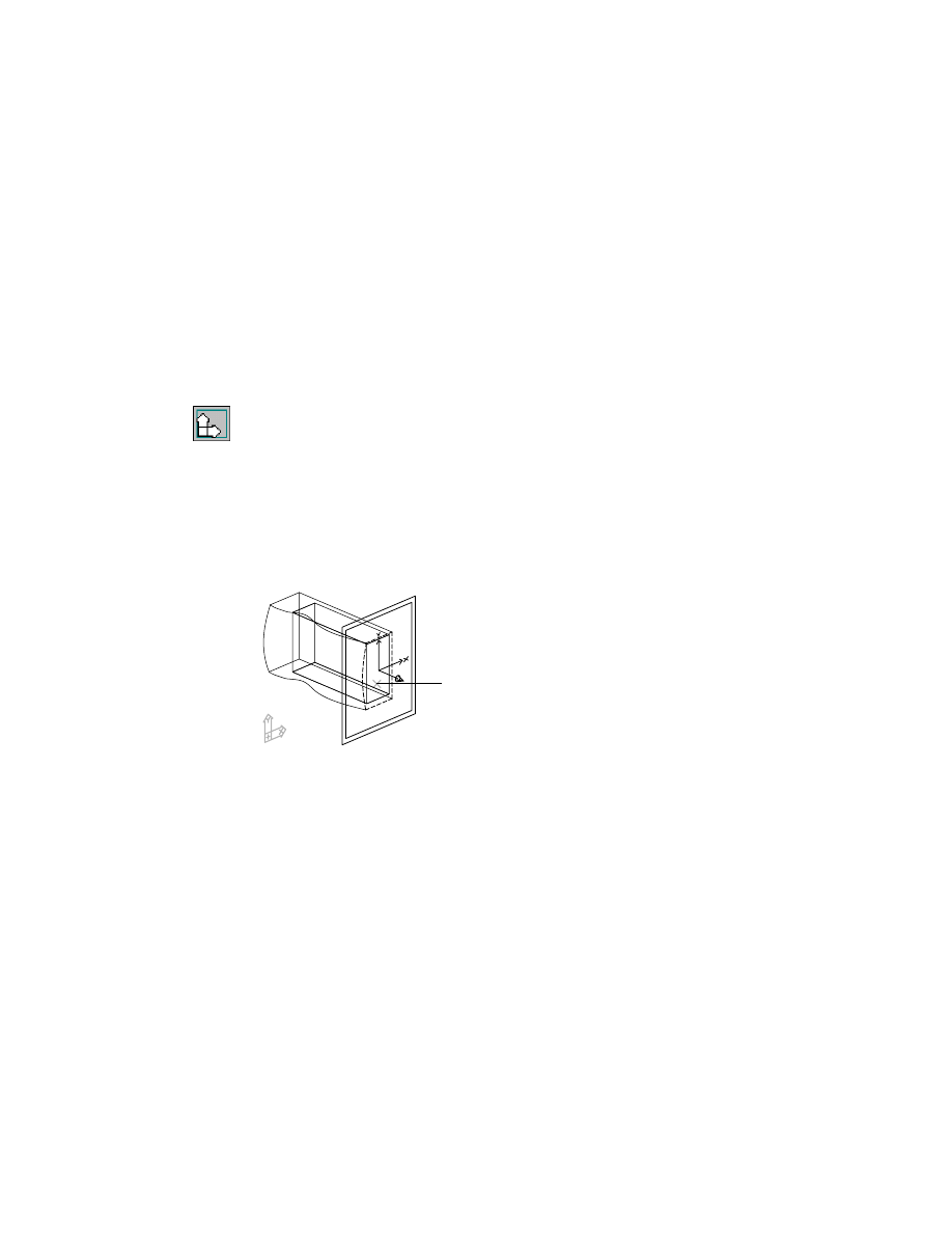
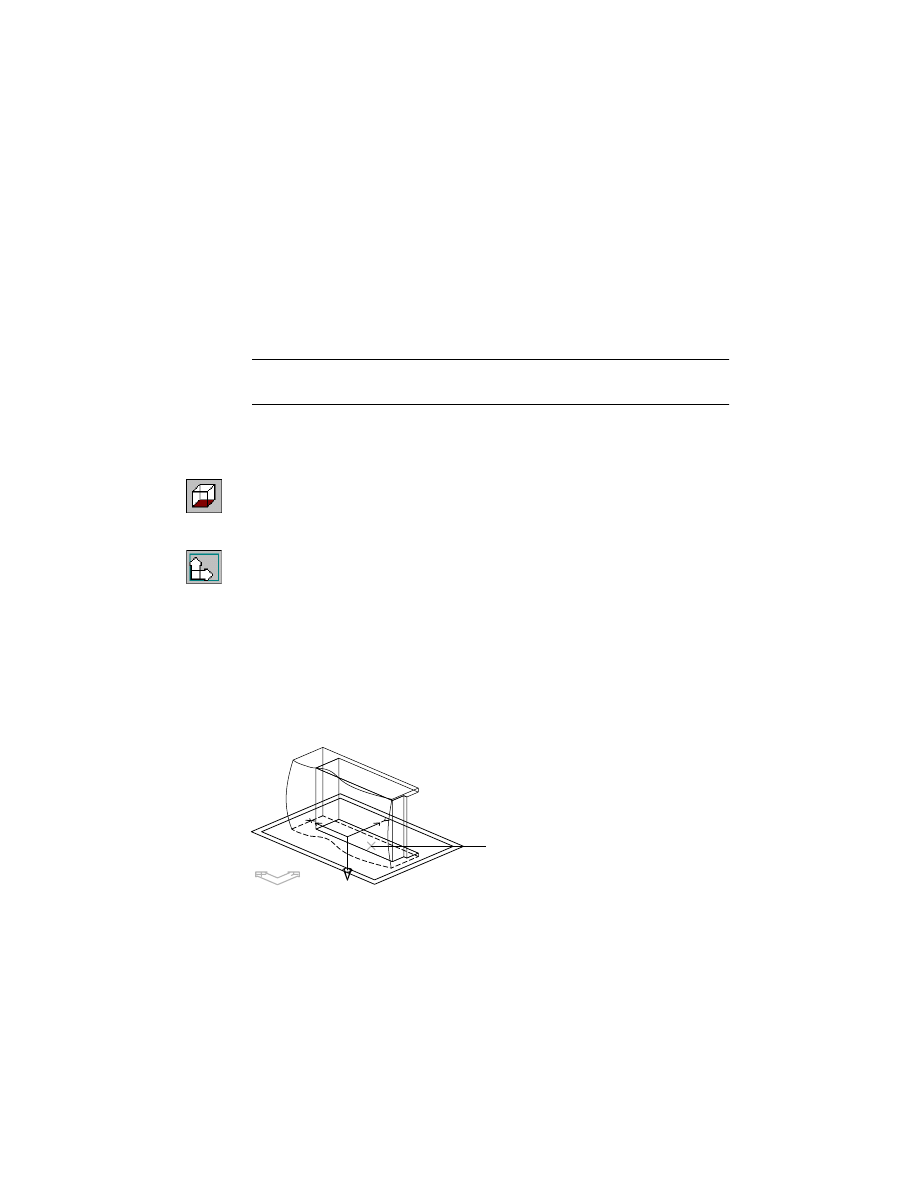
Attaching Surfaces Parametrically
Next, you create a work plane and work point and then dimension the work
point to the part. This dimension establishes a parametric relationship
between the surface and the part. The position of the surface is controlled by
the work point, and its orientation is controlled by the work plane associated
with the work point. Later, if you modify the position of the work point, the
surface location moves accordingly.
To position the work plane and work point easily, work in the isometric view.
To attach a surface to a part
1
Use
AMWORKPLN
to create a work plane.
Context Menu
In the graphics area, right-click and choose Sketched &
Work Features ➤ Work Plane.
In the Work Plane Feature dialog box, specify:
1st Modifier:
Planar Parallel
2nd Modifier:
Offset
Offset:
Enter 1
Create Sketch Plane:
Select the check box
Choose OK.
2
Position the offset work plane on the part, responding to the prompts.
Select work plane, planar face or [worldXy/worldYz/worldZx/Ucs]:
Select the front face of the camera (1)
Enter an option [Next/Accept] <Accept>:
Choose n to cycle to the front face, or press
ENTER
Enter an option [Flip/Accept] <Accept>:
Choose f to flip the direction arrow away from the camera body, or press
ENTER
Plane = Parametric
Select edge to align X axis or [Flip/Rotate/Origin] <Accept>:
Verify that the UCS icon is upright and press
ENTER
Attaching Surfaces Parametrically
|
583
You have created a parallel work plane offset from the front face of the part.
3
Use
AMWORKPT
to place a work point on the work plane, responding to the
prompts.
Context Menu
In the graphics area, right-click and choose Sketched &
Work Features ➤ Work Point.
Workpoint will be placed on the current sketch plane.
Specify the location of the workpoint:
Specify a location (2)
You have created a work point on the sketch plane.
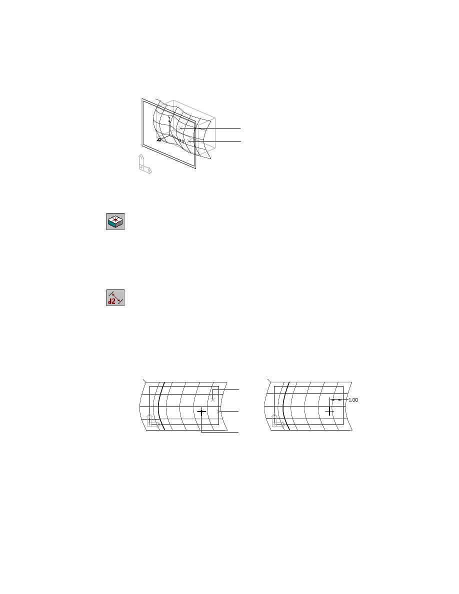
4
Use
AMPARDIM
to constrain the work point to the camera body, responding
to the prompts.
Context Menu
In the graphics area, right-click and choose Dimensioning
➤ New Dimension.
Select first object:
Select the work point (3)
Select second object or place dimension:
Select the right edge of the camera body (4)
Specify dimension placement:
Place the horizontal dimension (5)
Enter dimension value or [Undo/Hor/Ver/Align/Par/aNgle/Ord/Diameter/pLace]
<1.3316>:
Enter 1
Solved underconstrained sketch requiring 1 dimensions or constraints.
1
2
3
4
5
584
|
Chapter 20
Combining Parts and Surfaces
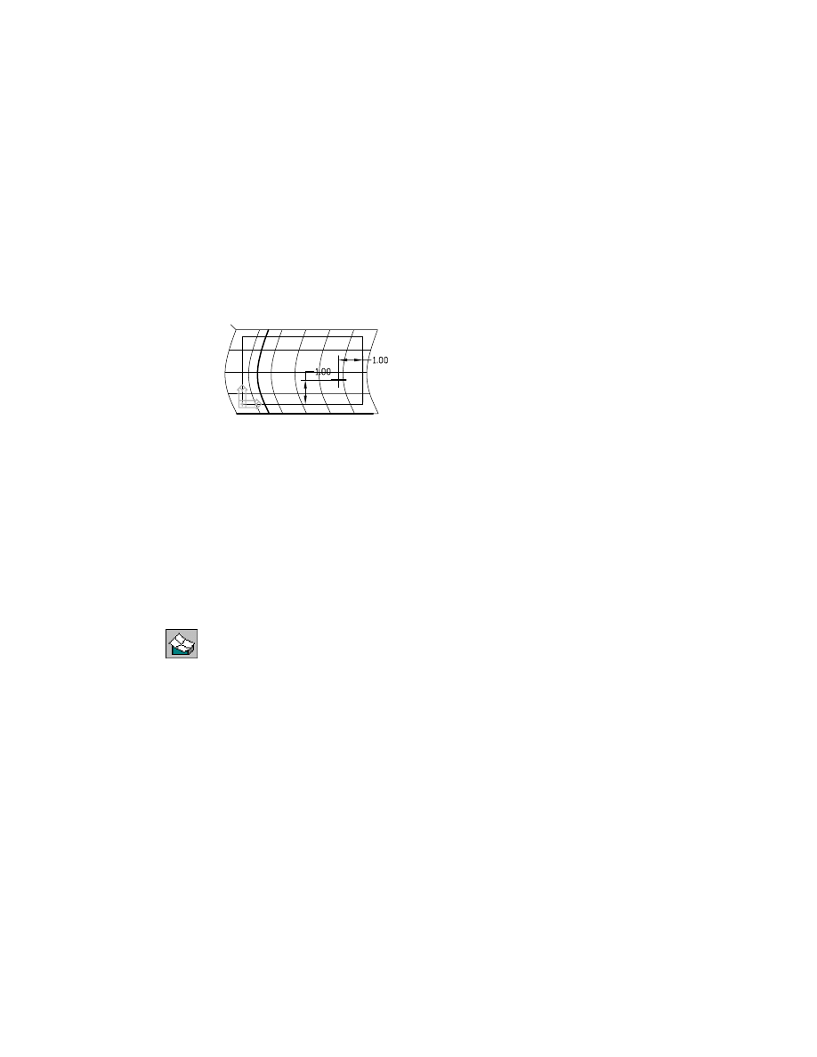
5
Continue on the command line.
Select first object:
Select the work point
Select second object or place dimension:
Select the bottom edge of the camera body
Specify dimension placement:
Place the vertical dimension
Enter dimension value or [Undo/Hor/Ver/Align/Par/aNgle/Ord/Diameter/pLace]
<0.8898>:
Enter 1
Solved fully constrained sketch.
Select first object:
Press
ENTER
The work point is fully constrained.
Save your file.
Cutting Parts with Surfaces
Now that the surface is positioned relative to the camera body, you can use
it to cut away material from the planar camera face.
To cut away from a part
1
Use
AMSURFCUT
to create a surface cut, responding to the prompts.
Context Menu
In the graphics area, right-click and choose Placed
Features ➤ Surface Cut.
(Type: Cut)
Select surface or [Type]:
Select the surface
Select work point:
Select the work point
Specify portion to remove: [Flip/Accept] <Accept>:
Verify the direction arrow points away from the camera body and press
ENTER
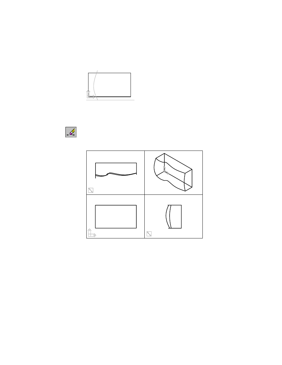
Cutting Parts with Surfaces
|
585
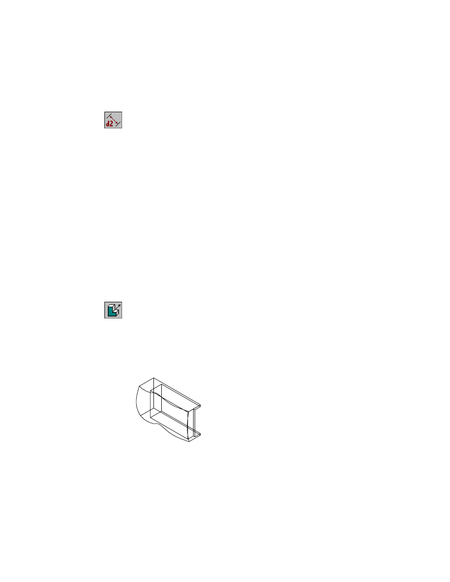
One side of the part is cut away, leaving the curved face of the surface. Your
model shows the modified block and the splines used to create the surface.
2
Use
REGENALL
to regenerate the drawing views.
Desktop Menu
View ➤ Regen All
3
Remove the three splines used to create the surface.
Context Menu
In the graphics area, right-click and choose 2D Sketching
➤ Erase.
4
Select the three splines and press
ENTER
.
Save your file.
586
|
Chapter 20
Combining Parts and Surfaces
Creating Extruded Features
The film compartment at the back of the base feature has two features—the
compartment and the door.
The camera back is a flat plane. You specify it as the sketch plane, sketch the
profile, and extrude it directly into the camera body.
To sketch the film compartment
1
Use
AMSKPLN
to create a new sketch plane, responding to the prompts. Work
in the isometric view.
Context Menu
In the graphics area, right-click and choose New Sketch
Plane.
Select work plane, planar face or [worldXy/worldYz/worldZx/Ucs]:
Select the back face of the camera (1)
Enter an option [Accept/Next] <Accept>:
Choose n to cycle to the back face, or press
ENTER
Plane = Parametric
Select edge to align X axis or [Flip/Rotate/Origin] <Accept>:
Select the bottom edge of the camera (2)
Plane = Parametric
Select edge to align X axis or [Flip/Rotate/Origin] <Accept>:
Verify that the X axis is pointing to the left and press
ENTER
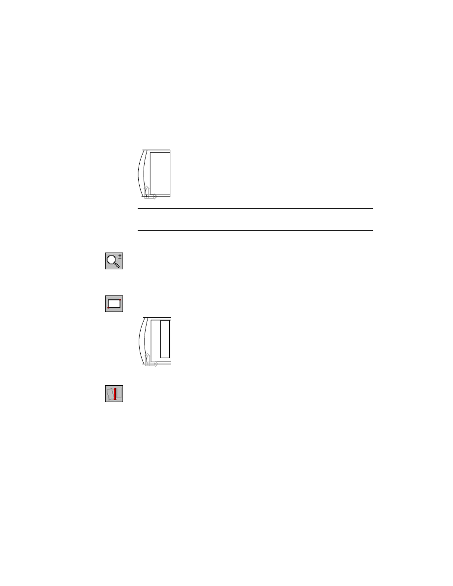
The back of the camera has been specified as the sketch plane. In the isomet-
ric view, the UCS icon is displayed with the X axis pointing left.
Next, change the view to see the back of the camera. If needed, zoom out to
see the entire back of the camera.
2
Change the front view to a back view.
Desktop Menu
View ➤ 3D Views ➤ Back
1
2
Creating Extruded Features
|
587
3
Use
RECTANG
to sketch a rectangle to the left on the camera back.
Context Menu
In the graphics area, right-click and choose 2D Sketching
➤ Rectangle.
4
Use
AMPROFILE
to create a profile from the sketch.
Context Menu
In the graphics area, right-click and choose Sketch Solving
➤ Single Profile.
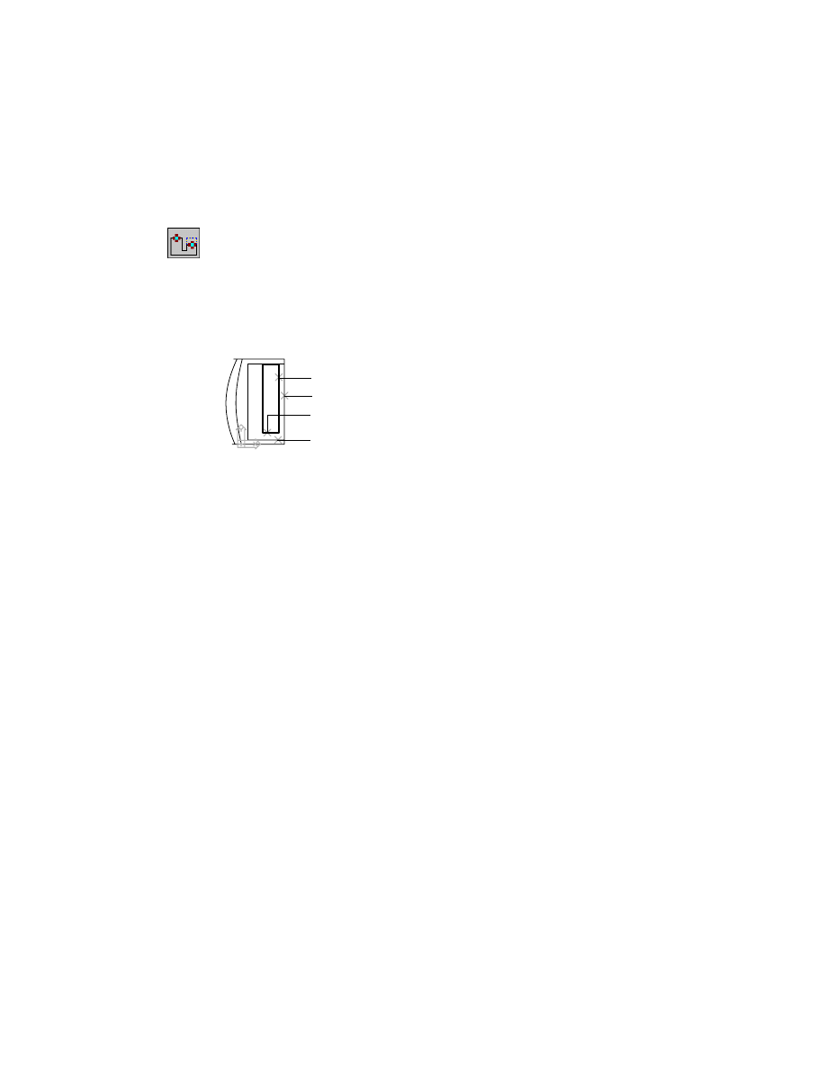
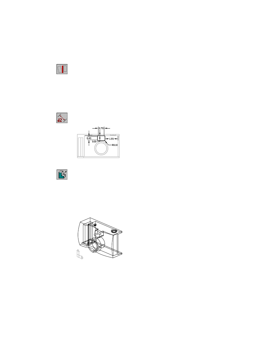
You need to place four dimensions or constraints: two to define the sketch
size and two to specify the sketch location on the camera body.
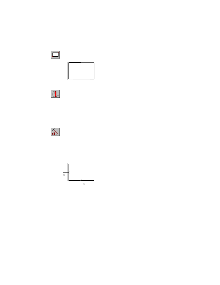
To add dimensions and constraints to the film compartment sketch
1
Use
AMPARDIM
to dimension the width of the rectangle, responding to the
prompts.
Context Menu
In the graphics area, right-click and choose Dimensioning
➤ New Dimension.
Select first object:
Select the bottom horizontal line of the sketch (1)
Select second object or place dimension:
Specify a location (2)
Enter dimension value or [Undo/Hor/Ver/Align/Par/aNgle/Ord/Diameter/pLace]
<3.7546>:
Enter 4
Solved underconstrained sketch requiring 3 dimensions or constraints.
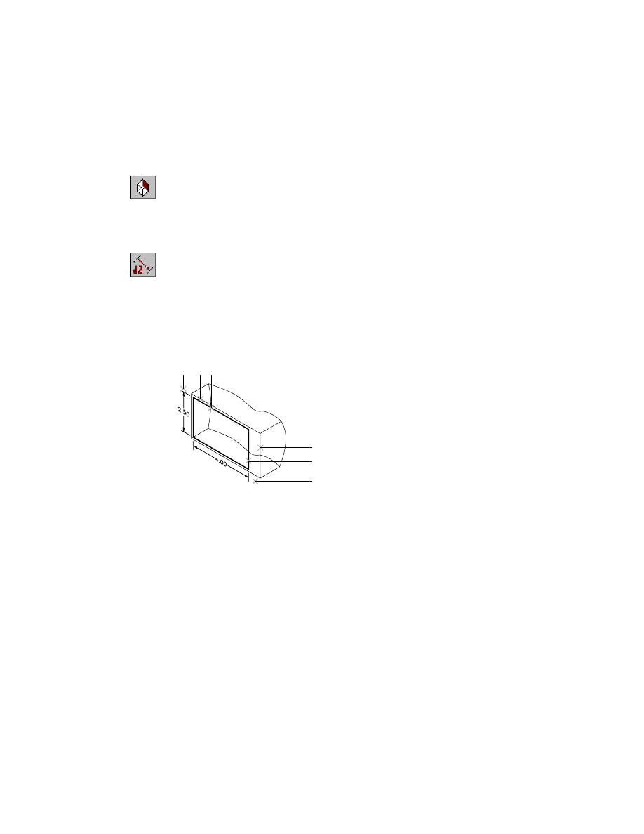
2
Define the height of the rectangle.
Select first object:
Select the left vertical line of the sketch (3)
Select second object or place dimension:
Specify a location (4)
Enter dimension value or [Undo/Hor/Ver/Align/Par/aNgle/Ord/Diameter/pLace]
<2.6011>:
Enter 2.5
Solved underconstrained sketch requiring 2 dimensions or constraints.
Select first object:
Press
ENTER
3
4
2
1
588
|
Chapter 20
Combining Parts and Surfaces
3
Make the isometric view active.
To see the dimensions and the profile sketch more clearly, rotate the isomet-
ric view until the back of the camera faces you.
Desktop Menu
View ➤ 3D Views ➤ Back Left Isometric
Define the distance between the top of the sketch and the top of the camera
back.
4
Use
AMPARDIM
to constrain the rectangle to the camera body, responding to
the prompts.
Context Menu
In the graphics area, right-click and choose Dimensioning
➤ New Dimension.
Select first object:
Select line (1)
Select second object or place dimension:
Select line (2)
Specify dimension placement:
Specify a location (3)
Enter dimension value or [Undo/Hor/Ver/Align/Par/aNgle/Ord/Diameter/pLace]
<0.2355>:
Enter .1626
Solved underconstrained sketch requiring 1 dimensions or constraints.
5
Define the distance between the right side of the sketch and the right edge
of the camera back.
Select first object:
Select line (4)
Select second object or place dimension:
Select line (5)
Specify dimension placement:
Specify a location (6)
Enter dimension value or [Undo/Hor/Ver/Align/Par/aNgle/Ord/Diameter/pLace]
<0.8583>:
Enter .8426
Solved fully constrained sketch.
Select first object:
Press
ENTER
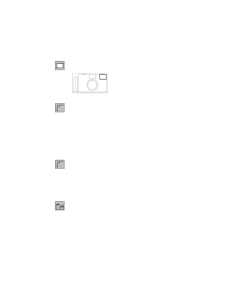
Next, cut the film compartment from the camera body.
5
4
6
3
2 1
Creating Extruded Features
|
589
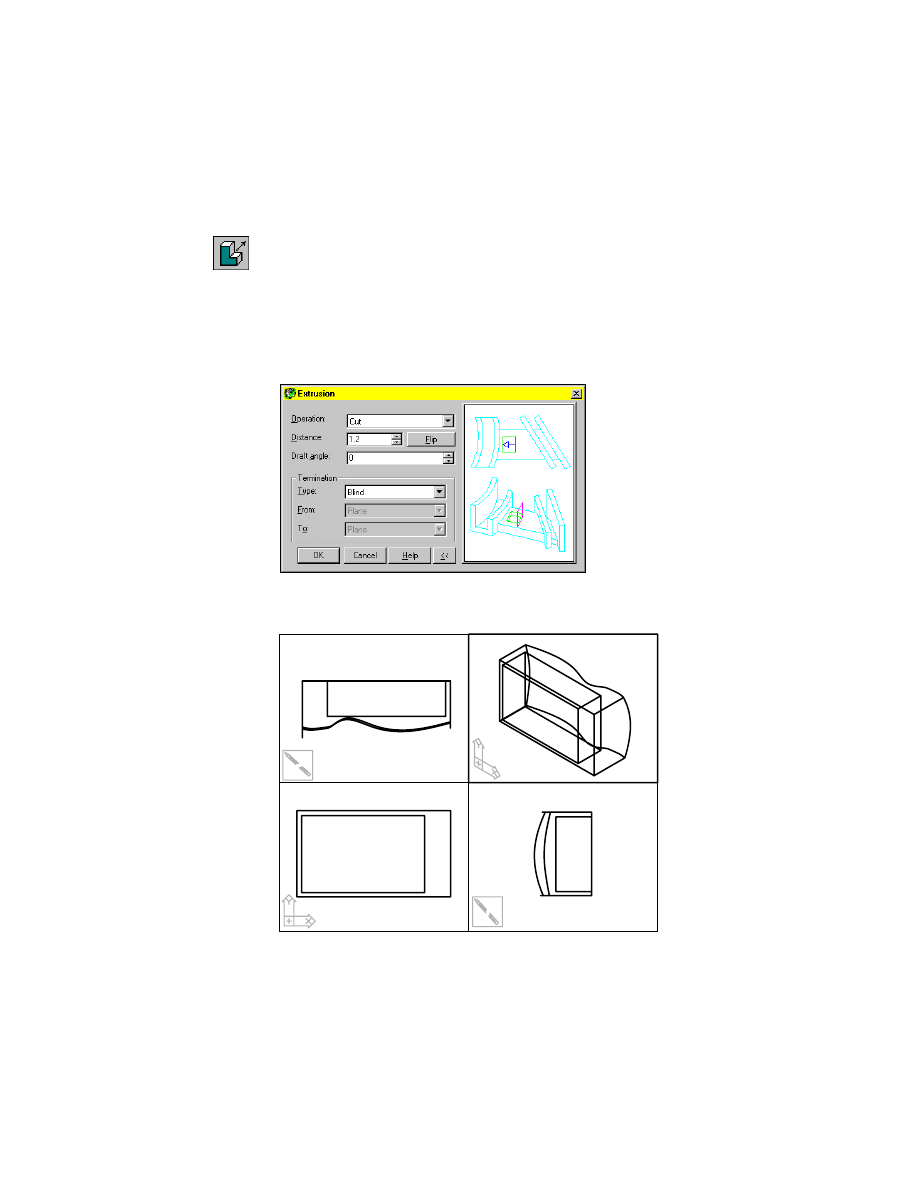
To cut the film compartment
1
Use
AMEXTRUDE
to cut the film compartment from the camera body.
Context Menu
In the graphics area, right-click and choose Sketched &
Work Features ➤ Extrude.
In the Extrusion dialog box, specify:
Operation:
Cut
Termination:
Blind
Distance:
Enter 1.2
Flip:
Point the direction arrow into the camera body
Choose OK.
The cut-out compartment is displayed in all four views.
590
|
Chapter 20
Combining Parts and Surfaces
2
Activate and then restore the viewports to the original orientation.
Upper right viewport:
Front Right Isometric View
Lower left viewport:
Front View
Cutting the door is similar to cutting the film compartment. You sketch a
rectangle on the right side of the camera and blindly extrude it as a cut into
the camera body.
To sketch the film compartment door
1
Use
AMSKPLN
to create a new sketch plane, responding to the prompts. Work
in the isometric view.
Context Menu
In the graphics area, right-click and choose New Sketch
Plane.
Select work plane, planar face or [worldXy/worldYz/worldZx/Ucs]:
Select the side face of the camera (1)
Enter an option [Accept/Next] <Accept>:
Verify that the side face is highlighted and press
ENTER
Plane = Parametric
Select edge to align X axis or [Flip/Rotate/Origin] <Accept>:
Verify that the Z axis points away from the camera and press
ENTER
1
Creating Extruded Features
|
591
2
Set the UCS origin to the lower-left corner of the right side of the camera,
responding to the prompts.
Desktop Menu
Assist ➤ New UCS ➤ Origin
Specify new origin point <0,0,0>:
Enter end
of:
Specify a point near the lower-left corner of the side view
NOTE
If the UCS icon does not snap to the lower-left corner of the camera,
set the AutoCAD system variable
UCSICON
to On.
3
In the side view, zoom in on the camera face.
Context Menu
In the graphics area, right-click and choose Zoom.
4
Hold down the left mouse button to size the view, and then press
ENTER
to
end the command.
5
Sketch a rectangular shape for the door cutout.
Context Menu
In the graphics area, right-click and choose 2D Sketching
➤ Rectangle.
6
Create the profile sketch.
Context Menu
In the graphics area, right-click and choose Sketch Solving
➤ Single Profile.
You need four dimensions or constraints to solve the sketch. Add constraints
that define the location of the profile on the camera side.
592
|
Chapter 20
Combining Parts and Surfaces
To constrain the film compartment door
1
Use
AMADDCON
to make the bottom edge of the profile sketch collinear with
the bottom line of the film compartment, responding to the prompts.
Context Menu
In the graphics area, right-click and choose 2D
Constraints ➤ Collinear.
Valid selection(s): line or spline segment
Select object to be reoriented:
Select line (1)
Valid selection(s): line or spline segment
Select object to be made collinear to:
Select line (2)
Solved underconstrained sketch requiring 3 dimensions or constraints.
2
Make the right side of the profile sketch collinear with the right edge of the
camera body.
Valid selection(s): line or spline segment
Select object to be reoriented:
Select line (3)
Valid selection(s): line or spline segment
Select object to be made collinear to:
Select line (4)
Solved underconstrained sketch requiring 2 dimensions or constraints.
Valid selection(s): line or spline segment
Select object to be reoriented:
Press
ENTER
Enter an option
[Hor/Ver/PErp/PAr/Tan/CL/CN/PRoj/Join/XValue/YValue/Radius/Length/Mir/Fix]
<eXit>:
Press
ENTER
3
1
2
4
Creating Extruded Features
|
593
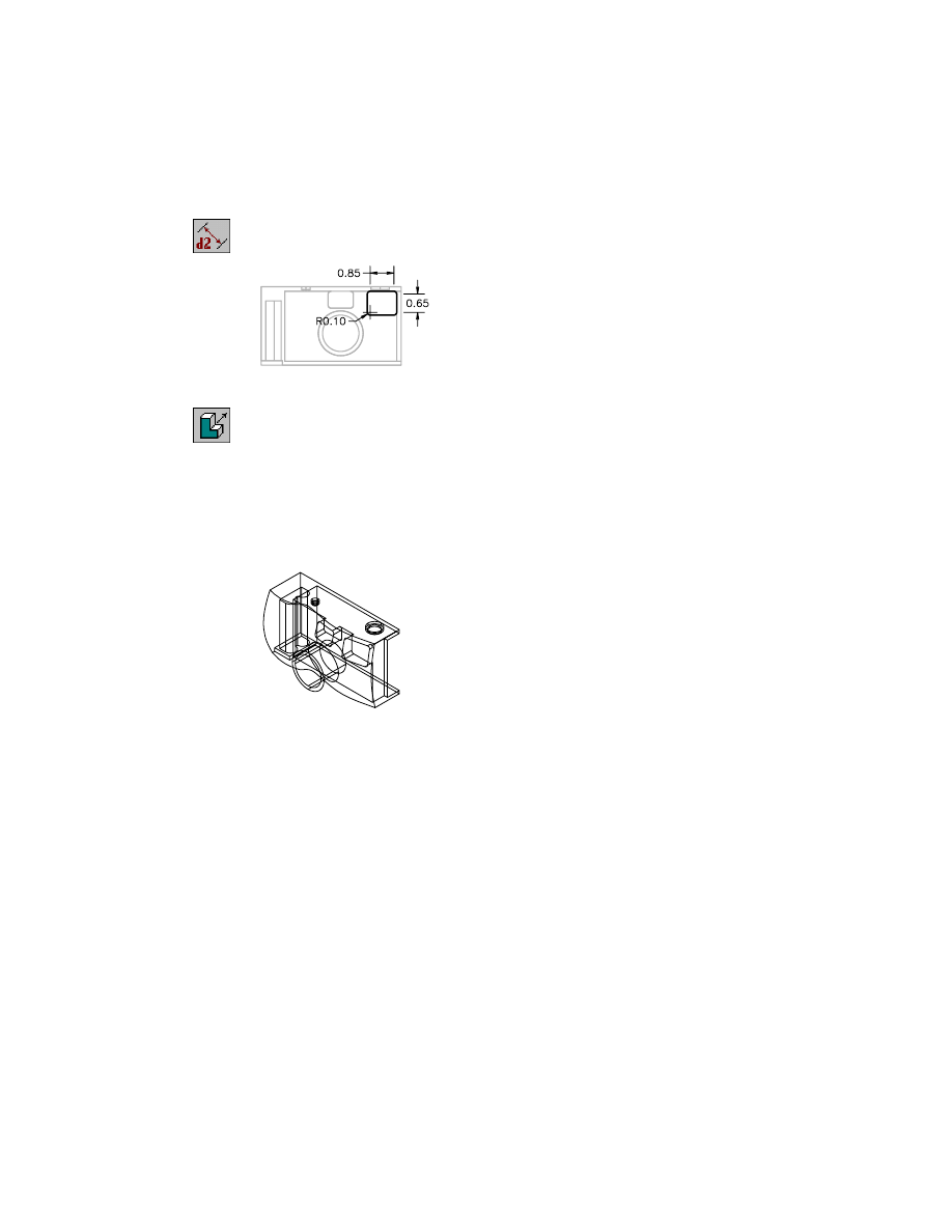
3
Use
AMPARDIM
to dimension the width and height of the profile sketch,
responding to the prompts.
Context Menu
In the graphics area, right-click and choose Dimensioning
➤ New Dimension.
Select first object:
Select a horizontal profile edge
Select second object or place dimension:
Place the horizontal dimension
Enter dimension value or [Undo/Hor/Ver/Align/Par/aNgle/Ord/Diameter/pLace]
<0.6840>:
Enter .6
Solved underconstrained sketch requiring 1 dimensions or constraints.
Select first object:
Select a vertical profile edge
Select second object or place dimension:
Place the vertical dimension
Enter dimension value or [Undo/Hor/Ver/Align/Par/aNgle/Ord/Diameter/pLace]
<2.3218>:
Enter 2.5
Solved fully constrained sketch.
Select first object:
Press
ENTER
The horizontal dimension makes the width of the profile equal to half the
depth of the film compartment and the height of the profile equal to the
height of the compartment.
For practice, express the width and height of the profile as equations.
To cut the film compartment door
1
Use
AMEXTRUDE
to cut the profile from the camera body.
Context Menu
In the graphics area, right-click and choose Sketched &
Work Features ➤ Extrude.
In the Extrusion dialog box, specify:
Operation:
Cut
Termination:
Blind
Distance:
Enter .1574
Flip:
Point the direction arrow into the camera
594
|
Chapter 20
Combining Parts and Surfaces
2
Choose OK to create the extrusion.
Save your file.
The battery compartment also has a cutout for a door. The order in which
you create these features does not matter, but the natural order would be to
create the film compartment first.
The cutout for the battery compartment is more complicated because of its
shape. The key to creating this feature is to locate the sketch plane properly
on the bottom left side of the camera body.
NOTE
Watch the UCS icon in the isometric view and make sure it is positioned
on the bottom of the camera.
To sketch the battery compartment
1
Change the top view to a bottom view.
Desktop Menu
View ➤ 3D Views ➤ Bottom
2
Use
AMSKPLN
to create a new sketch plane, responding to the prompts. Work
in the isometric view.
Context Menu
In the graphics area, right-click and choose New Sketch
Plane.
Select work plane, planar face or [worldXy/worldYz/worldZx/Ucs]:
Select the bottom face of the camera (1)
Plane = Parametric
Select edge to align X axis or [Flip/Rotate/Origin] <Accept>:
Verify that the Z axis arrow points down, away from the camera body
Plane = Parametric
Select edge to align X axis or [Flip/Rotate/Origin] <Accept>:
Verify that the X axis points to the left and press
ENTER
1
Creating Extruded Features
|
595
3
Use
PLINE
to sketch the profile of the battery compartment on the bottom of
the camera body. Work in the bottom view.
Context Menu
In the graphics area, right-click and choose 2D Sketching
➤ Polyline.
4
Use
AMPROFILE
to create the profile sketch.
Context Menu
In the graphics area, right-click and choose Sketch Solving
➤ Single Profile.
The sketch needs seven to nine dimensions or constraints, depending on
how precisely you drew the sketch. If you need more than seven constraints,
you need to add some missing geometric constraints.
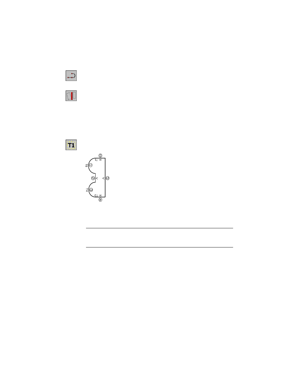
To constrain the battery compartment
1
Use
AMSHOWCON
to view the current geometric constraints.
Context Menu
In the graphics area, right-click and choose 2D
Constraints ➤ Show Constraints.
2
Add any missing geometric constraints.
Typically, the radial (R) constraints and one of the tangent (T) constraints are
missing from the arcs.
NOTE
When you add constraints, the sketch shape might become distorted,
but you can restore it when you complete the dimensions. Dimension the largest
vertical dimension and the arcs before you dimension smaller objects.
596
|
Chapter 20
Combining Parts and Surfaces
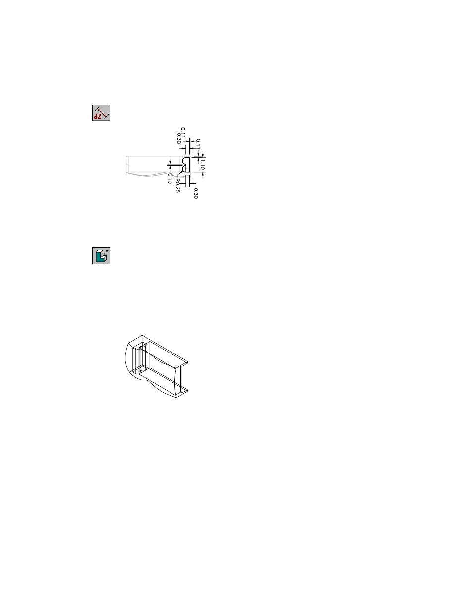
3
Use
AMPARDIM
to add the following dimensions.
Context Menu
In the graphics area, right-click and choose Dimensioning
➤ New Dimension.
The sketch is fully constrained.
To cut the battery compartment
1
Use
AMEXTRUDE
to cut the profile from the camera body.
Context Menu
In the graphics area, right-click and choose Sketched &
Work Features ➤ Extrude.
In the Extrusion dialog box, specify:
Operation:
Cut
Termination:
Blind
Distance:
Enter 2.4
Flip:
Point the direction arrow into the camera body
Choose OK.
The door opening of the battery compartment is located on the same plane
as the battery compartment. Therefore, you need only to sketch and con-
strain a rectangle, cutting it into the camera body to the proper depth.
Creating Extruded Features
|
597
To sketch and constrain the battery compartment door
1
Use
RECTANG
to sketch the profile of the cutout. Work in the bottom view.
Context Menu
In the graphics area, right-click and choose 2D Sketching
➤ Rectangle.
2
Use
AMPROFILE
to create the profile sketch.
Context Menu
In the graphics area, right-click and choose Sketch Solving
➤ Single Profile.
The sketch requires four dimensions or constraints.
3
Use
AMADDCON
to constrain the sketch to the bottom of the camera body.
Context Menu
In the graphics area, right-click and choose 2D
Constraints ➤ Collinear.
Select lines that make the outside edges of the sketch collinear with the out-
side edges of the camera body.
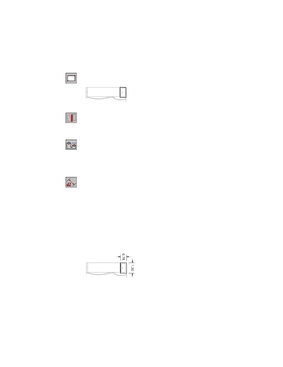
4
Use
AMPARDIM
to dimension the length and width of the profile sketch,
responding to the prompts.
Context Menu
In the graphics area, right-click and choose Dimensioning
➤ New Dimension.
Select first object:
Select the narrow side of the rectangle
Select second object or place dimension:
Place the horizontal dimension
Enter dimension value or [Undo/Hor/Ver/Align/Par/aNgle/Ord/Diameter/pLace]
<0.7463>:
Enter .76
Solved underconstrained sketch requiring 1 dimensions or constraints.
Select first object:
Select the long side of the rectangle
Select second object or place dimension:
Place the vertical dimension
Enter dimension value or [Undo/Hor/Ver/Align/Par/aNgle/Ord/Diameter/pLace]
<1.1274>:
Enter 1.3
Solved fully constrained sketch.
Select first object:
Press
ENTER
The sketch is fully constrained.
598
|
Chapter 20
Combining Parts and Surfaces
To cut the battery compartment door
1
Use Extrude to cut the door opening from the camera body. Make sure the
direction of the cut is into the camera body.
Context Menu
In the graphics area, right-click and choose Sketched &
Work Features ➤ Extrude.
In the Extrusion dialog box, specify:
Operation:
Cut
Termination:
Blind
Distance:
Enter .1574
Flip:
Point the direction arrow into the camera body
Choose OK.
Save your file.
Creating Holes
Both the shutter release and the film advance mounts are counterbored holes
that you can create as placed features.
To create shutter release and film advance mount holes
1
Change the upper-left viewport to a top view.
Desktop Menu
View ➤ 3D Views ➤ Top
2
Zoom in to enlarge the view as needed, and then activate the isometric view.
3
Use
AMHOLE
to place the holes for the shutter release and the film advance.
Context Menu
In the graphics area, right-click and choose Placed
Features ➤ Hole.
Creating Holes
|
599
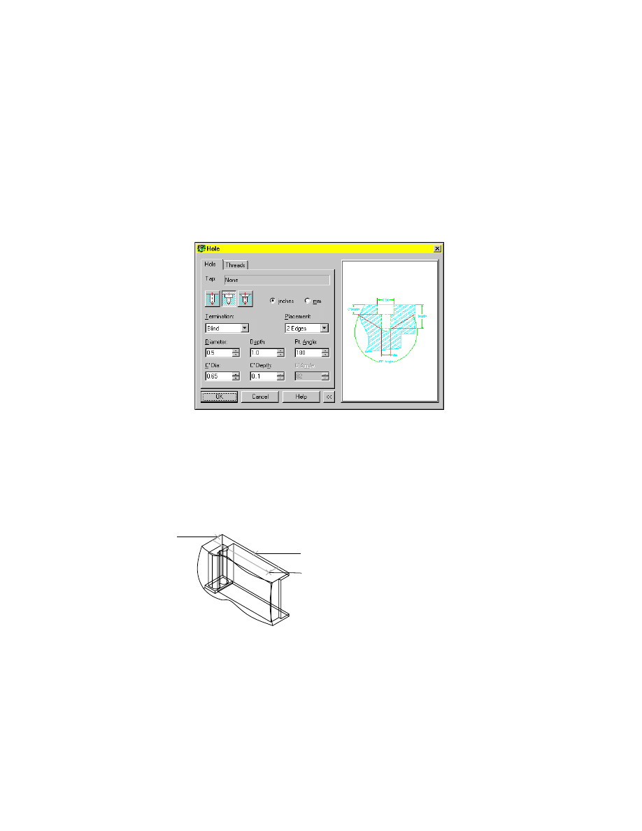
In the Hole dialog box, select the Counterbore hole type icon and specify:
Termination:
Blind
Placement:
2 Edges
Dia:
Enter .5
Depth:
1.0
Pt. Angle:
Enter 180
C’Dia:
Enter .65
C’Depth:
Enter 1
Choose OK.
4
Respond to the prompts as follows:
Select the first edge:
Select the top, back edge in the isometric view (1)
Select the second edge:
Select the top, left edge in the isometric view (2)
Specify the hole location:
Specify a location (3)
Enter the distance from first edge (highlighted) <0.4146>:
Enter .5
Enter the distance from second edge (highlighted) <4.3456>:
Enter 4.25
Select the first edge:
Press
ENTER
1
2
3
600
|
Chapter 20
Combining Parts and Surfaces
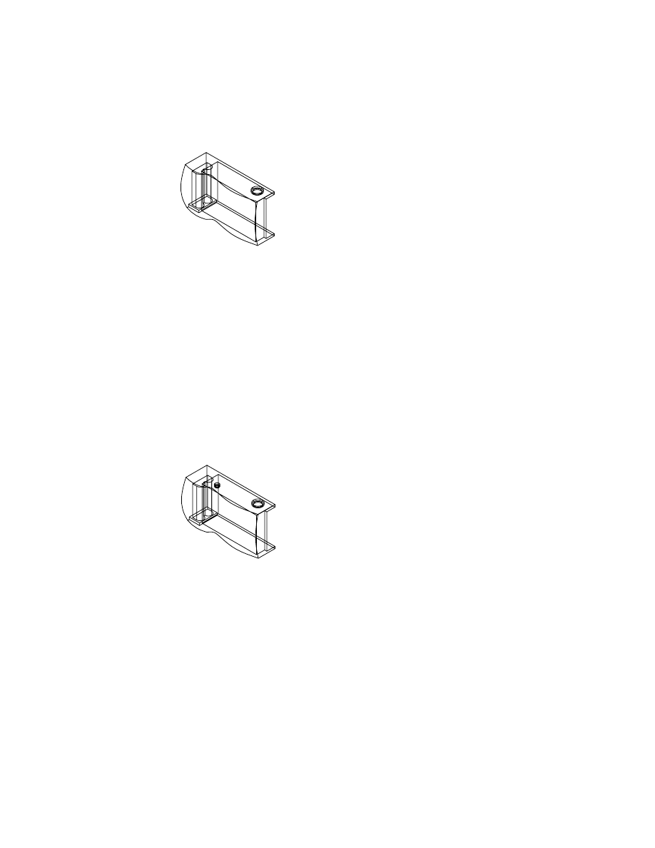
A hole is created for the film advance component.
5
Press
ENTER
to redisplay the Hole Feature dialog box. Specify:
Operation:
C’Bore
Termination:
Blind
Placement
2 Edges
Drill Size:
Custom, enter .2 diameter, 1.0 depth, and 180 degrees point angle
C’bore/Sunk Size:
Enter .3 diameter and .1 depth and choose OK
6
Respond to the prompts as follows:
Select the first edge:
Select the top, back edge in the isometric view
Select the second edge:
Select the top, left edge in the isometric view
Specify the hole location:
Specify a location
Enter the distance from first edge (highlighted) <0.6946>:
Enter .85
Enter the distance from second edge (highlighted) <1.7487>:
Enter 1.6
Select the first edge:
Press
ENTER
A hole is created for the shutter release mount.
Save your file.
Creating Features on a Work Plane
|
601
Creating Features on a Work Plane
The camera body is complete except for features on the camera face. Unlike
the previous features, you sketch these features on a work plane parallel to
the front of the camera. You extrude the features from the work plane and
into the camera body to the correct depth.
You sketch on the work plane because 2D sketches cannot be drawn and pro-
filed on a NURBS surface.
The lens sheath, a hollow cylinder joined to the face of the camera, has two
features: a solid cylinder and a circle used to cut out the center of the
cylinder.
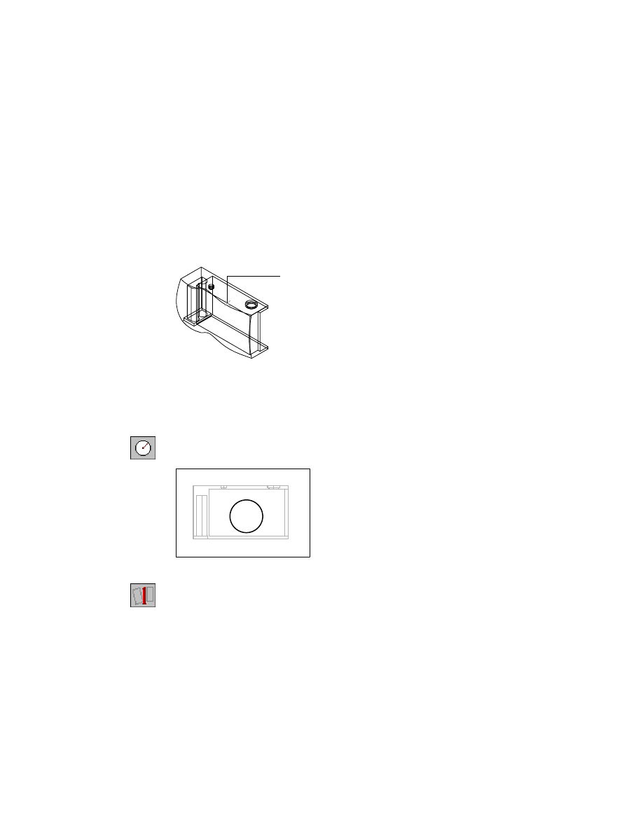
To extrude the lens sheath on a work plane
1
Use
AMWORKPLN
to create a new work plane on which to locate the sketch
plane.
Context Menu
In the graphics area, right-click and choose Sketched &
Work Features ➤ Work Plane.
In the Work Plane Feature dialog box, specify:
1st Modifier:
Planar Parallel
2nd Modifier:
Offset
Offset:
Enter 1.25
Create Sketch Plane:
Select the check box
Choose OK.
602
|
Chapter 20
Combining Parts and Surfaces
2
Respond to the prompts as follows:
Select work plane, planar face or [worldXy/worldYz/worldZx/Ucs]:
Specify a point (1)
Enter an option [Next/Accept] <Accept>:
Press
ENTER
when the front of the camera is selected
Enter an option [Flip/Accept] <Accept>:
Verify that the work plane is offset from the camera front and press
ENTER
Plane = Parametric
Select edge to align X axis or [Flip/Rotate/Origin] <Accept>:
Point the Z axis away from the camera front and press
ENTER
The work plane is created in front of the camera face. Because the sketch
plane is specified on the work plane, the UCS icon is also displayed on the
work plane.
3
Use
CIRCLE
to sketch a circle in front of the camera face. Work in the front
view.
Context Menu
In the graphics area, right-click and choose 2D Sketching
➤ Circle.
4
Use
AMPROFILE
to create the profile sketch.
Context Menu
In the graphics area, right-click and choose Sketch Solving
➤ Single Profile.
1
Creating Features on a Work Plane
|
603
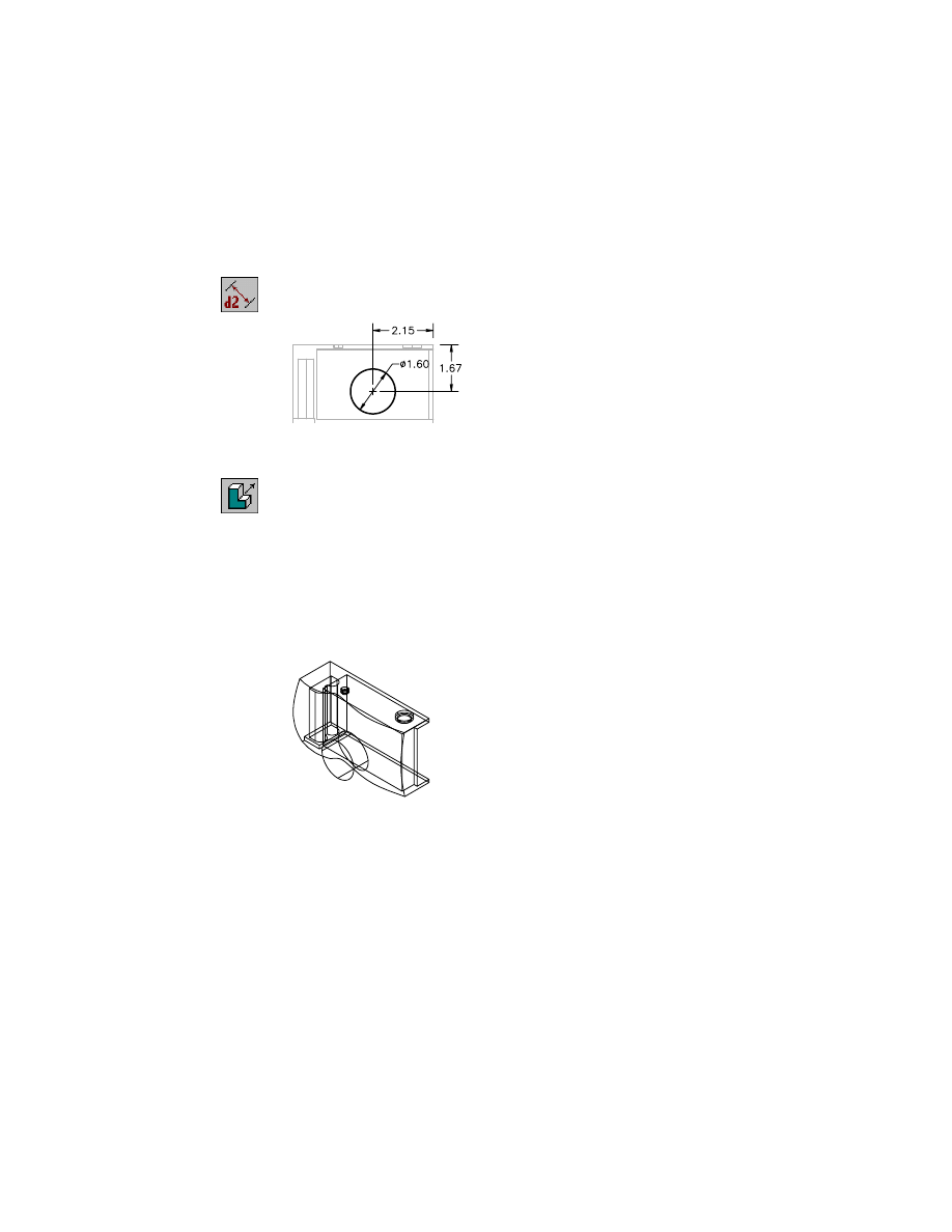
To position the circle, you need three dimensions or constraints: a diameter
and two dimensions to locate the circle on the sketch plane relative to the
camera body.
5
Use
AMPARDIM
to dimension the sketch with the following values.
Context Menu
In the graphics area, right-click and choose Dimensioning
➤ New Dimension.
6
Use
EXTRUDE
to extrude the profile to create the outer cover of the lens
sheath. Work in the isometric view.
Context Menu
In the graphics area, right-click and choose Sketched &
Work Features ➤ Extrude.
In the Extrusion dialog box, specify:
Operation:
Join
Termination:
Blind
Distance:
Enter 1.25
Flip:
Point the direction arrow into the camera body
Choose OK.
The lens sheath is complete. Now, cut a smaller cylinder to hollow out the
sheath.
604
|
Chapter 20
Combining Parts and Surfaces
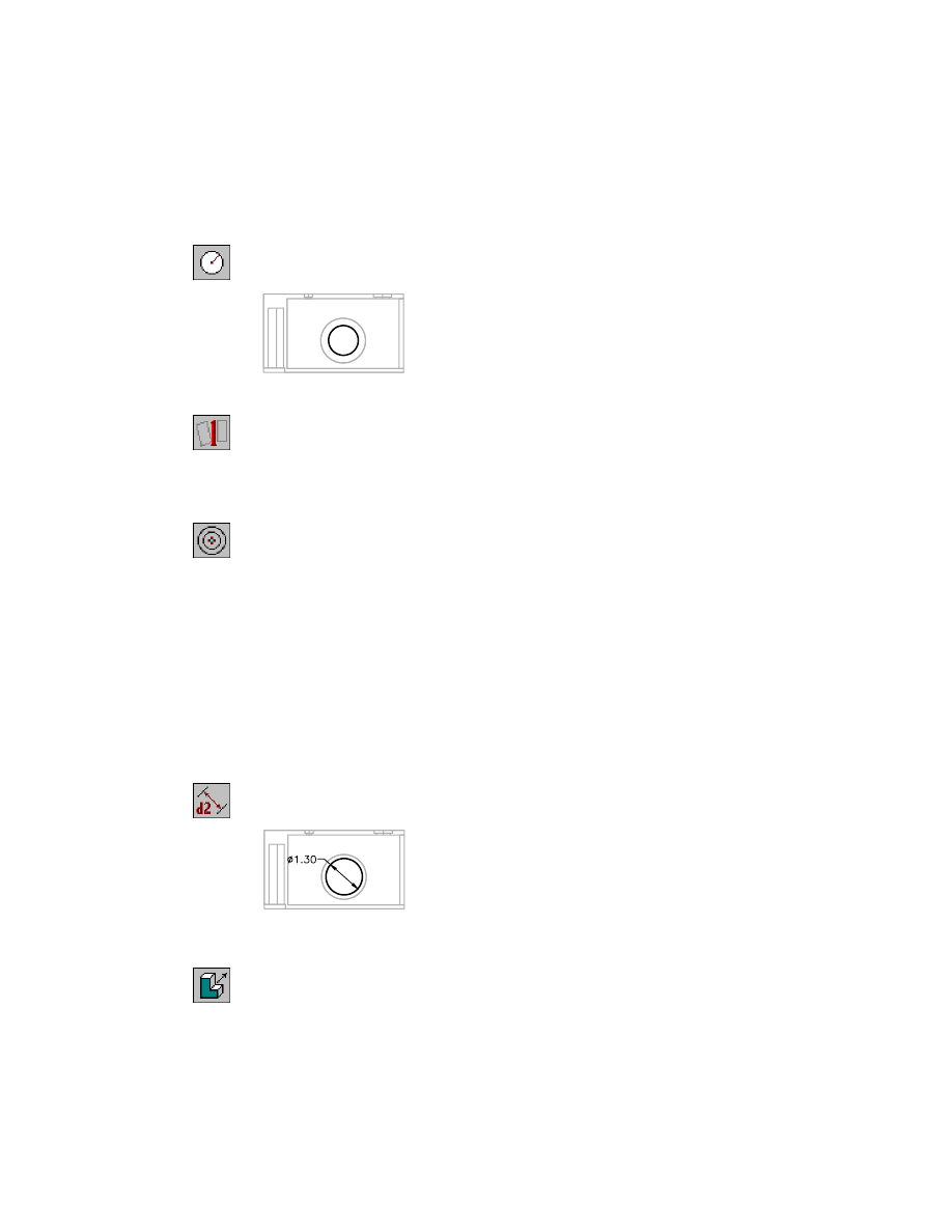
To hollow out the lens sheath
1
Activate the front view, and sketch a circle on the work plane.
Context Menu
In the graphics area, right-click and choose 2D Sketching
➤ Circle.
2
Profile the sketch.
Context Menu
In the graphics area, right-click and choose Sketch Solving
➤ Single Profile.
Three dimensions or constraints are needed to solve the sketch.
3
Use
AMADDCON
to constrain the sketch to be concentric with the lens
sheath, responding to the prompts.
Context Menu
In the graphics area, right-click and choose 2D
Constraints ➤ Concentric.
Valid selection(s): arc, circle, or ellipse
Select object to be reoriented:
Select the small circle
Valid selection(s): arc, circle, ellipse, or work point
Select object to be made concentric to:
Select the large circle
Solved underconstrained sketch requiring 1 dimensions or constraints.
Valid selection(s): arc, circle, or ellipse
Select object to be reoriented:
Press
ENTER
Enter an option
[Hor/Ver/PErp/PAr/Tan/CL/CN/PRoj/Join/XValue/YValue/Radius/Length/Mir/Fix]
<eXit>:
Press
ENTER
4
Use
AMPARDIM
to dimension the sketch to the value shown.
Context Menu
In the graphics area, right-click and choose Dimensioning
➤ New Dimension.
5
Make the isometric view active and use
AMEXTRUDE
to extrude the sketch to
hollow out the lens sheath.
Context Menu
In the graphics area, right-click and choose Sketched &
Work Features ➤ Extrude.
Creating Features on a Work Plane
|
605
In the Extrusion dialog box, specify:
Operation:
Cut
Termination:
Through
Flip:
Point the direction arrow into the camera body
Choose OK.
Save your file.
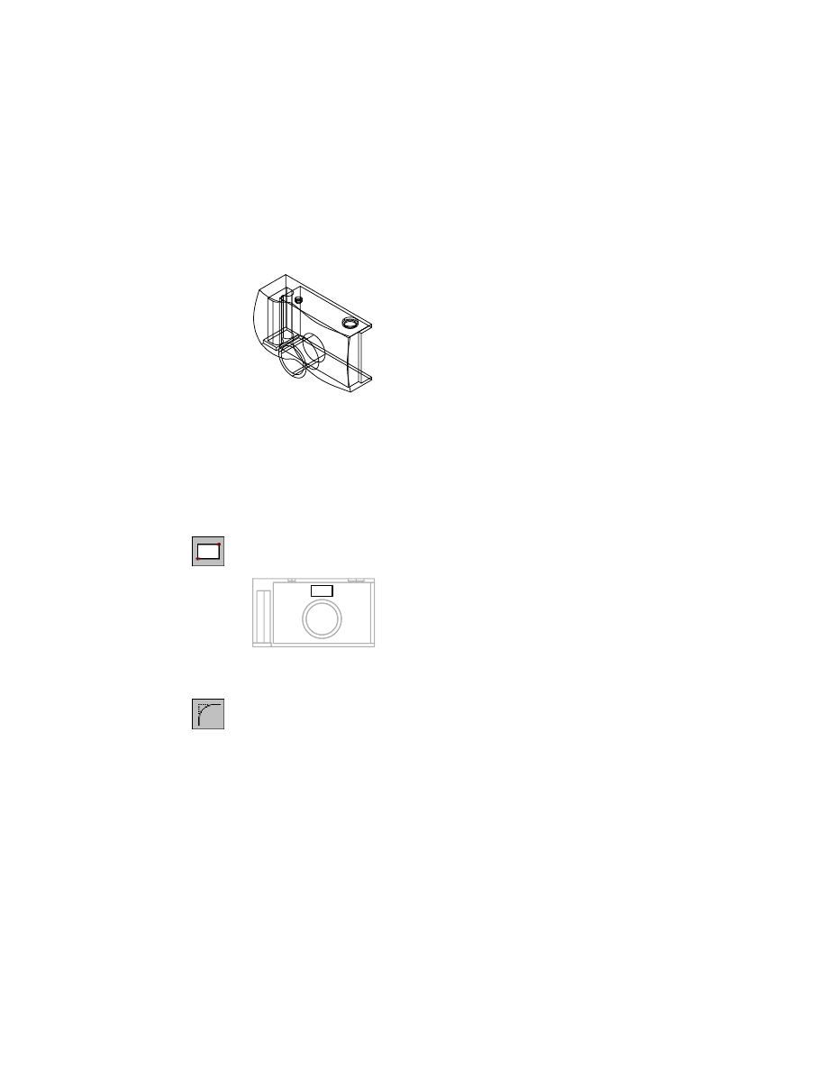
Next, you create the viewfinder compartment, a filleted rectangle that is cut
from the camera face.
To cut the viewfinder compartment
1
Use
RECTANG
to sketch a rectangle on the sketch plane above the lens sheath.
Work in the isometric view.
Context Menu
In the graphics area, right-click and choose 2D Sketching
➤ Rectangle.
2
Use FILLET to define the fillet for the corners of the rectangle, responding to
the prompts.
Context Menu
In the graphics area, right-click and choose 2D Sketching
➤ Fillet.
Current settings: Mode = TRIM, Radius = 0.5000
Select first object or [Polyline/Radius/Trim]:
Enter r
Specify fillet radius <0.5000>:
Enter .1, and choose OK.
3
Press
ENTER
to restart
FILLET
. Apply the fillet, responding to the prompts.
Current settings: Mode = TRIM, Radius = 0.1000
Select first object or [Polyline/Radius/Trim]:
Enter p
Select 2D polyline:
Specify the rectangle
606
|
Chapter 20
Combining Parts and Surfaces
4
Use
AMPROFILE
to create the profile sketch.
Context Menu
In the graphics area, right-click and choose Sketch Solving
➤ Single Profile.
You need five or more dimensions or constraints to solve the sketch. Add the
dimensions for the length and width of the shape, one dimension for the fil-
lets, and two dimensions to locate the sketch in relationship to the camera
body.
5
In the front view, zoom in to enlarge the model as needed.
6
Use
AMPARDIM
to add the following dimensions.
Context Menu
In the graphics area, right-click and choose Dimensioning
➤ New Dimension.
7
Use
AMEXTRUDE
to cut the sketch through the camera body.
Context Menu
In the graphics area, right-click and choose Sketched &
Work Features ➤ Extrude.
In the Extrusion dialog box, specify:
Operation:
Cut
Termination:
Through
Flip:
Point the direction arrow into the camera body
Choose OK.
The last feature is the flash compartment. It has a shape similar to the view-
finder but is larger and located in the upper-right corner of the camera face.
Creating Features on a Work Plane
|
607
To cut the flash compartment
1
Sketch a rectangle to the right of the viewfinder.
Context Menu
In the graphics area, right-click and choose 2D Sketching
➤ Rectangle.
2
Define a fillet for the corners of the rectangle, responding to the prompts.
Context Menu
In the graphics area, right-click and choose 2D Sketching
➤ Fillet.
Current settings: Mode = TRIM, Radius = 0.5000
Select first object or [Polyline/Radius/Trim]:
Enter r
Specify fillet radius <0.5000>:
Enter .1
3
Press
ENTER
to restart
FILLET
. Apply the fillet, responding to the prompts.
Current settings: Mode = TRIM, Radius = 0.1000
Select first object or [Polyline/Radius/Trim]:
Enter p
Select 2D polyline:
Specify the rectangle
4
Create the profile sketch.
Context Menu
In the graphics area, right-click and choose Sketch Solving
➤ Single Profile.
You need five or more dimensions or constraints to solve the sketch, just as
you did when you sketched the viewfinder. Dimension the length, width,
and the fillets, and locate the sketch in relationship to the camera body.
Zoom in on the front view as needed.
5
Use
AMADDCON
to make the top and right edges of the sketch collinear with
the upper-right corner of the film compartment.
Context Menu
In the graphics area, right-click and choose 2D
Constraints ➤ Collinear.
608
|
Chapter 20
Combining Parts and Surfaces
6
Add the following dimensions.
Context Menu
In the graphics area, right-click and choose Dimensioning
➤ New Dimension.
7
Extrude the sketch to cut it through the camera body.
Context Menu
In the graphics area, right-click and choose Sketched &
Work Features ➤ Extrude.
In the Extrusion dialog box, specify:
Operation:
Cut
Termination:
Through
Flip:
Point the direction arrow into the camera body
Choose OK.
Save your file.
Modifying Designs
|
609
Modifying Designs
As with all projects, designs change during the development process. For
example, you might want to scale the camera to a smaller size and change
the dimension that positions the camera face on the solid model. Because
you want both the surface and the camera body at the same scale, you first
resize them.
In this exercise, you specify a percentage of the camera’s current size. Then,
to position the surface on the camera proportionately, you modify the para-
metric dimension.
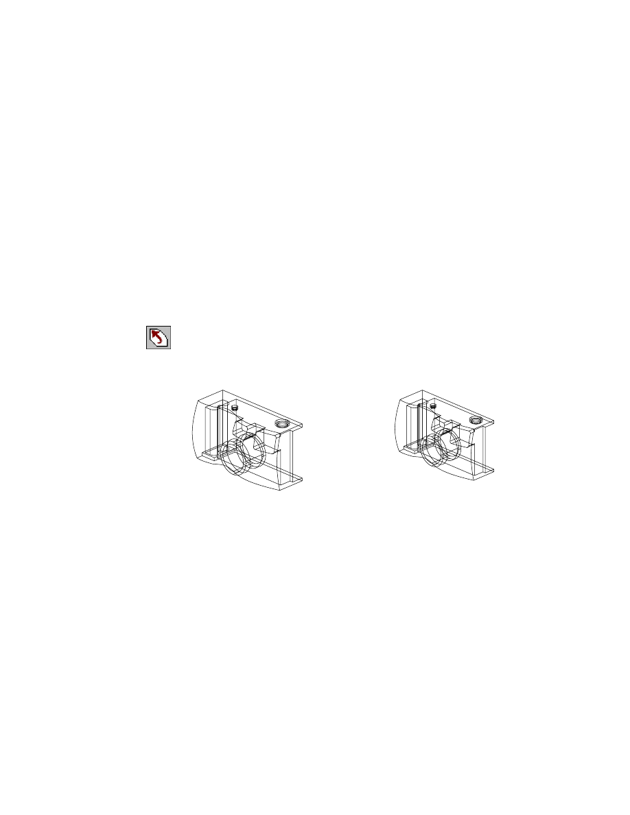
To scale the camera body and face
1
Zoom in to magnify the isometric view.
2
Use
SCALE
to reduce the scale of the part, responding to the prompts.
Desktop Menu
Modify ➤ Scale
Select objects:
Select the camera and press
ENTER
Specify base point:
Select the rear corner of the camera
Specify scale factor or [Reference] <1.0000>:
Enter .9 and press
ENTER
The camera and surface are resized to 90 percent of their original size. The
surface and other features retain their original geometric relationships.
full-scale camera body
scaled camera body
610
|
Chapter 20
Combining Parts and Surfaces
To reposition the camera face
1
Use
AMEDITFEAT
to edit the surfcut feature, responding to the prompts.
Context Menu
In the graphics area, right-click and choose Edit Features
➤ Edit.
Enter an option [Sketch/surfCut/Toolbody/select Feature] <select Feature>:
Enter c
Select surfcut feature:
Select a curved edge of the surface
The original sketch, work plane, and work point are displayed.
2
Use
AMMODDIM
to modify the dimension that positions the surface to the
work point, responding to the prompts.
Context Menu
In the graphics area, right-click and choose Dimensioning
➤ Edit Dimension.
Select dimension to change:
Select the horizontal dimension
New value for dimension <0.9>:
Enter .75
Select dimension to change:
Press
ENTER
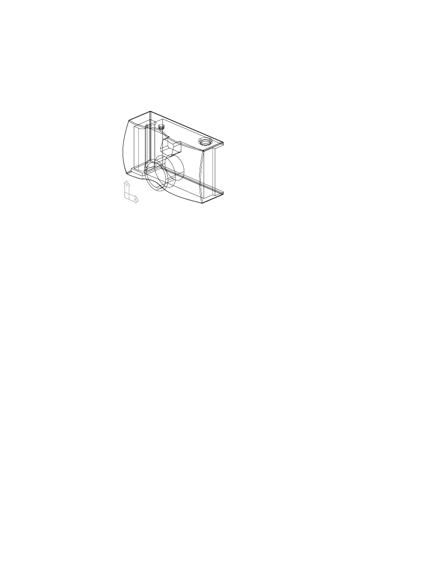
3
Use
AMUPDATE
to update the part.
Context Menu
In the graphics area, right-click and choose Update Part.
The surface is repositioned on the camera with the new value.
Finishing Touches on Models
|
611
Finishing Touches on Models
The finishing touch for the camera body is to fillet the corners where the dif-
ferent sides meet.
To finish the camera body
1
Use
AMVISIBLE
to hide the work plane from your display.
Desktop Menu
Part ➤ Part Visibility
2
In the Desktop Visibility dialog box, select the Part tab and choose Work
Planes and Hide. Choose OK.
3
Use
ISOLINES
to increase the number of isolines. Change the value to 8 to
show more detail on the model. The display will change when you edit your
model.
4
Use
AMFILLET
to fillet the camera body.
Context Menu
In the graphics area, right-click and choose Placed
Features ➤ Fillet.
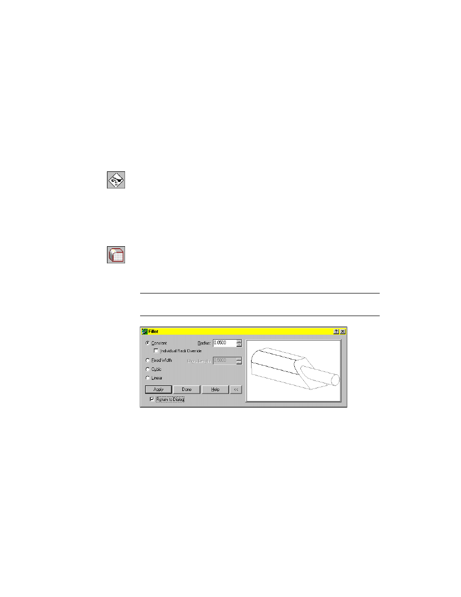
5
In the Fillet dialog box, specify Constant using a fillet radius of .05. Select
Return to Dialog and choose Apply.
NOTE
To speed up filleting a complex model, select only a few lines at a time.
Repeat the command with more lines until the filleting is finished.
612
|
Chapter 20
Combining Parts and Surfaces
6
Fillet the outside corners and edges of the camera body. When you are
finished, choose Done.
The camera body is finished.
Wyszukiwarka
Podobne podstrony:
Ch17 Combine Parts
surfacefinishmetrologyiss1 140102202845 phpapp01
Okidata Okipage 14e Parts Manual
Kyocera FS 1010 Parts Manual
Brother PT 2450 Parts Manual
Dance, Shield Modelling of sound ®elds in enclosed spaces with absorbent room surfaces
Autonomic Nerve (Palmar Surface) tapeSP
A10VO Series 31 Size 28 Service Parts list
Akumulator do?UTZ?HR COMBINE HARVESTERS M3370 M3380
Fly Model 030 B17G interiors some custom parts
Cell surface in the interaction Nieznany
Ch12 Shafts with Standard Parts
PARTS MANUAL TL120 BT3Z001 1(21200008~)
1998 Bustillo Surface Micromach Nieznany (2)
Body Parts 3
Dynapower Model 66 & 99 Modular Controls Parts
więcej podobnych podstron