205
In This Chapter
12
Creating Shafts With
Standard Parts
In AutoCAD
®
Mechanical 6, you learn how to use the
shaft generator to create and edit shafts. You learn to
insert bearings and perform bearing calculations.
■
Configuring the snap options
■
Starting and configuring the shaft
generator
■
Creating shaft sections
■
Inserting a profile
■
Inserting a chamfer and a fillet
■
Inserting a shaft break
■
Creating a side view
■
Inserting a thread
■
Editing and inserting a shaft
section
■
Replacing a shaft section
■
Inserting a bearing

206
|
Chapter 12
Creating Shafts With Standard Parts
Key Terms
Term
Definition
bearing calculation
Calculates limiting value, dynamic and static load rating, dynamic and static
equivalent load, and fatigue life in revolutions and hours.
chamfer
A beveled surface between two faces or surfaces.
dynamic calculation
Calculation required for a revolving bearing. The result is the Adjusted Rating Life.
This is the life associated with 90% reliability with contemporary, commonly used
material, and under conventional operating conditions. With the number of
revolutions you get the life in working hours.
dynamic dragging
The act of determining the size of a standard part with the cursor while inserting
it into a side view. The standard part is displayed dynamically on the screen and
can be dragged to the next possible size and length. The values (sizes) are taken
from the Standard parts database.
fillet
A curved transition from one part face or surface to another. The transition cuts
off the outside edge or fills in the inside edge.
gear
Any several arrangements, especially of toothed wheels in a machine, which allow
power to be passed from one part to another to control the power, speed, or
direction of movement.
radius reflection line
Thin line that represents the radius in the side or top view.
shaft break
Interruption of a shaft. A shaft can be interrupted at a point, and the shaft break
symbols are inserted in a suitable size.
shaft generator
Tool to draw rotationally symmetrical parts. A shaft is usually created from left to
right using different sections. These sections are positioned automatically one
after the other. Additionally, any shaft section can be inserted, deleted, or edited.
Creating Shafts with Standard Parts
|
207
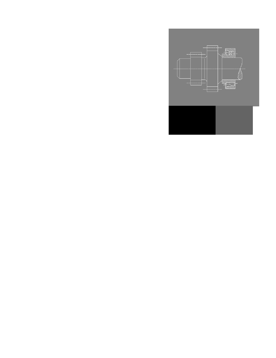
Creating Shafts with Standard Parts
In this section you generate a shaft with standard parts with the shaft generator.
You also perform a bearing calculation.
First, you have to start with an ISO drawing template.
To open a template
1
Open a new drawing.
Menu
File ➤ New
Command
NEW
The AutoCAD Today dialog box is displayed.
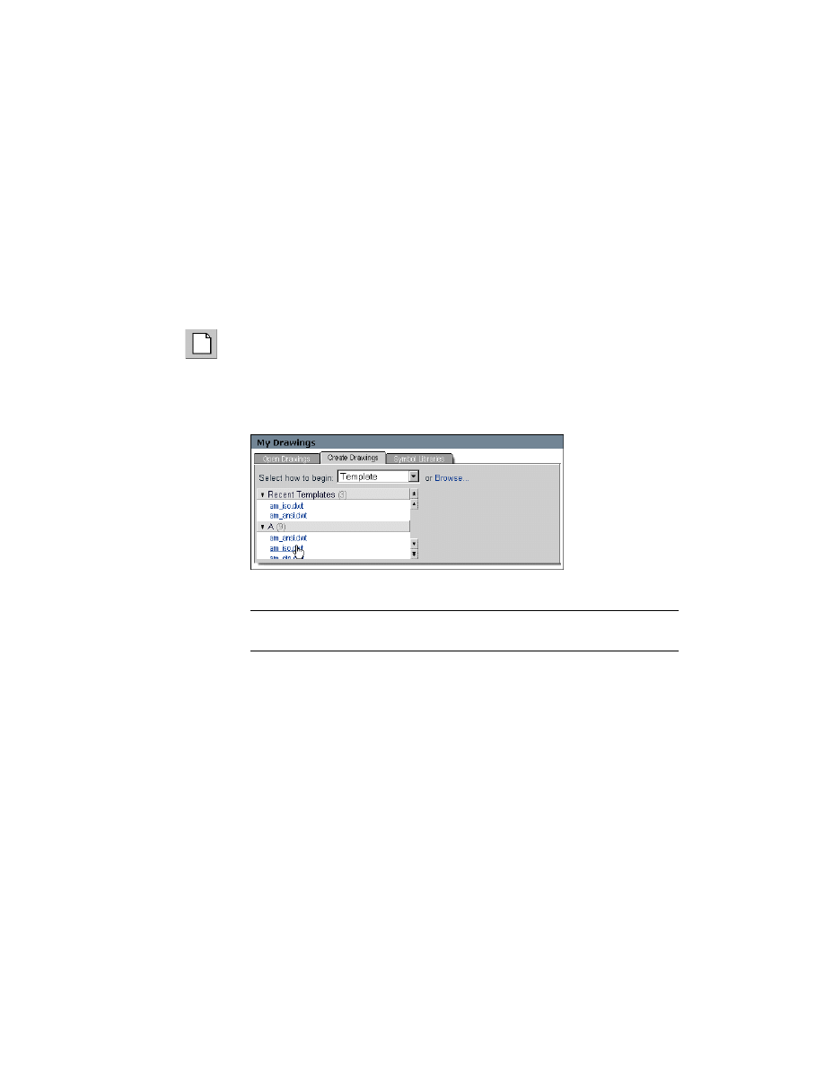
2
In the Today dialog box, in the section My Drawings, change to the tab
Create Drawings and select the template am_iso.dwt.
This opens a new drawing template.
NOTE
The ISO standard part standard has to be installed for this tutorial
exercise.
Configuring the Snap Options
First, you configure the snap options.
208
|
Chapter 12
Creating Shafts With Standard Parts
To configure the snap options
1
Start the Power Snap Settings.
Menu
Assist ➤ Draft Settings ➤ Power Snap Settings 1-4
Command
AMPOWERSNAP
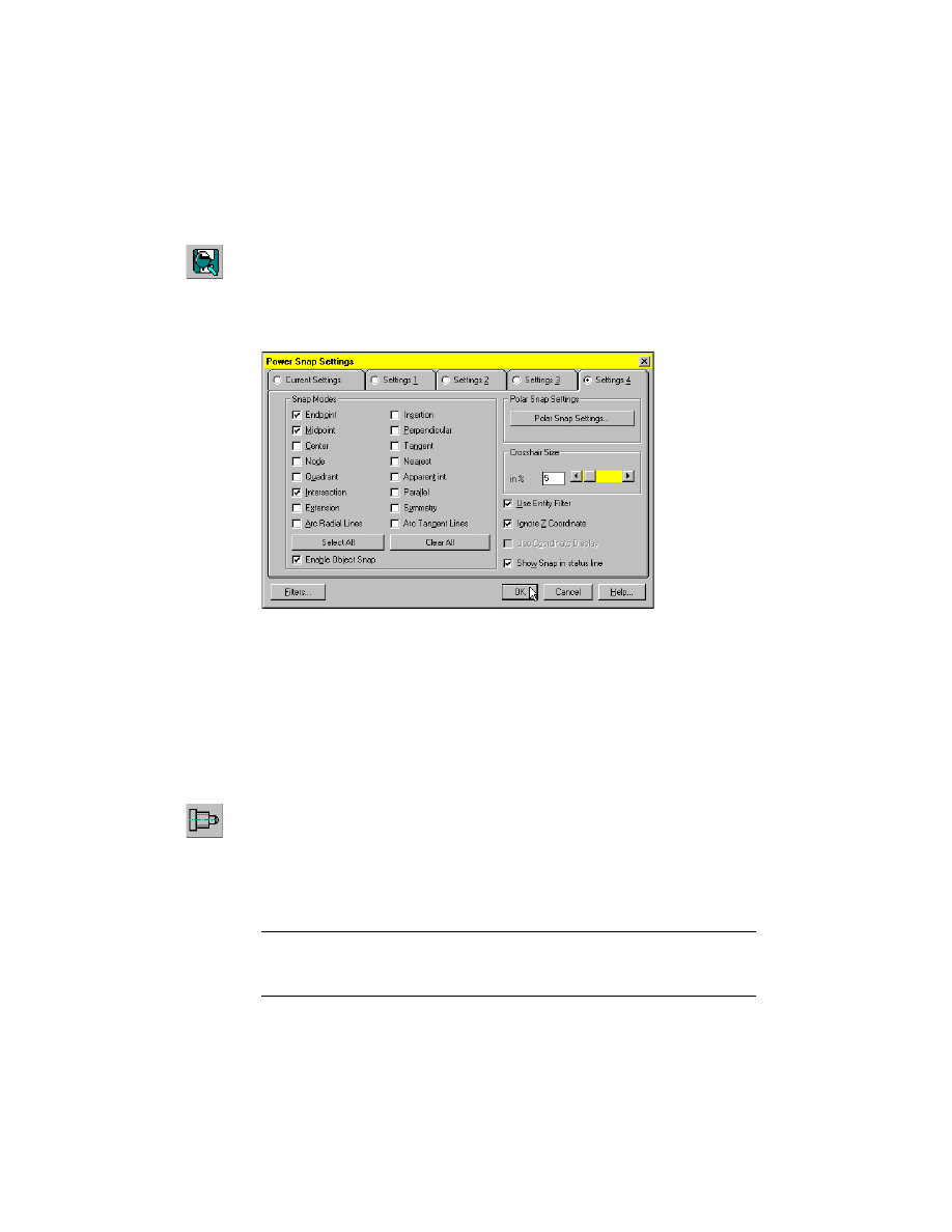
2
In the Power Snap Settings dialog box, activate the tab Setting 4 and specify:
Snap Modes:
Endpoint, Midpoint, Intersection
Choose OK
Save your file.
Starting and Configuring Shaft Generators
In the next steps, you start and configure the shaft generator.
To start and configure the shaft generator
1
Start the Shaft Generator command.
Menu
Content ➤ Shaft Generator
Command
AMSHAFT2D
2
Respond to the prompts as follows:
Specify starting point or select center line [New shaft]:
Enter 150,150
Specify centerline endpoint:
Enter 240,150
NOTE
The start and endpoints of the centerline are only important in deter-
mining the direction. The length of the centerline is automatically adapted to the
length of the shaft.
Creating Shafts with Standard Parts
|
209
3
In the Shaft Generator dialog box, press the appropriate button, and enter
the values as indicated in the following:
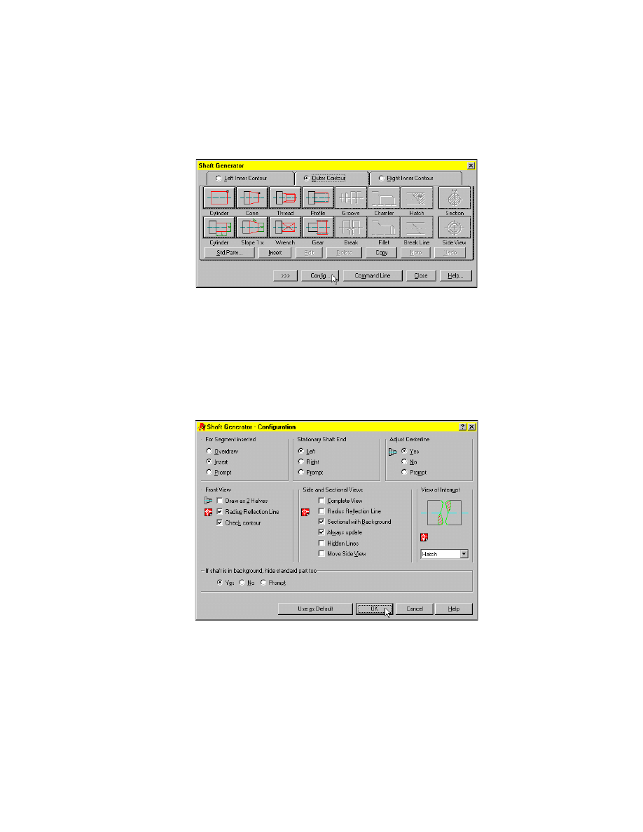
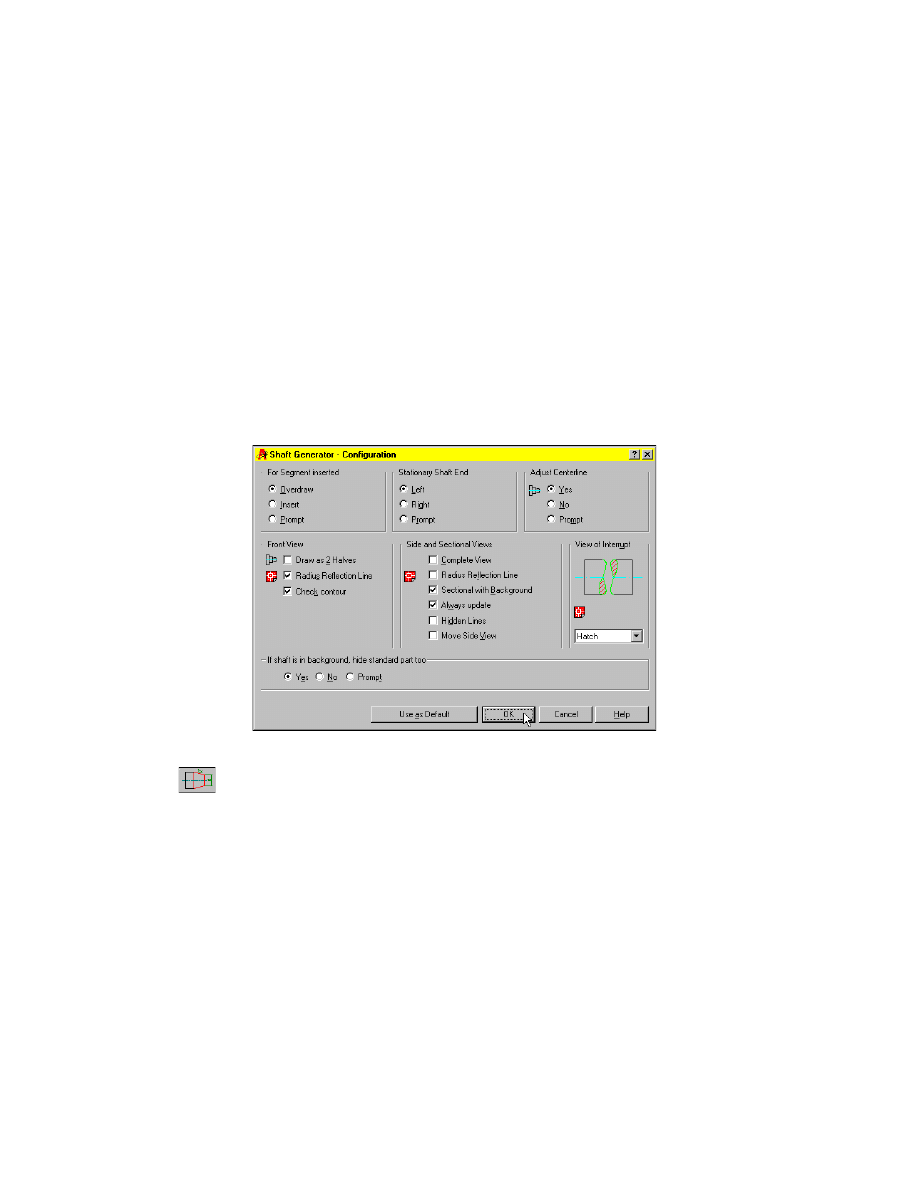
4
Choose the Config button to start the Shaft Generator Configuration, and
specify:
For Segment inserted:
Insert
Stationary Shaft End:
Left
Adjust Centerline:
Yes
Front View:
Radius Reflection Line, Check contour
Side and Sectional Views:
Sectional with Background, Always update
View of Interrupt:
Hatch
If shaft is in background, hide standard part too:
Yes
Choose OK.
You return to the Shaft Generator dialog box.
210
|
Chapter 12
Creating Shafts With Standard Parts
Creating Cylindrical Shaft Sections and Gears
The shaft generator is configured. Now you want to generate the first shaft
segments.
To create shaft segments
1
Choose the lower cylinder button to define a cylinder section, and respond
to the prompts as follows:
Specify length <50>:
Enter 12
Specify diameter <40>:
Enter 20
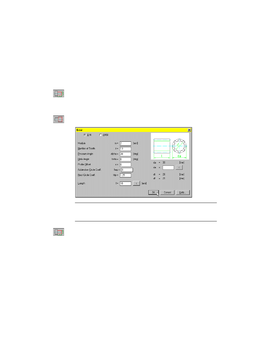
2
Choose the gear button, and enter the values for module, number of teeth,
and length as shown in the following figure:
NOTE
Here, the DIN standard requires that you indicate the module. The
ANSI standard requires the reciprocal 1/module. You can switch between these
two representations using the DIN and ANSI toggle.
3
Choose the lower cylinder button to define a further cylinder section and
respond to the prompts as follows:
Specify length <10>:
Enter 5
Specify diameter <20>:
Enter 20
Creating Shafts with Standard Parts
|
211
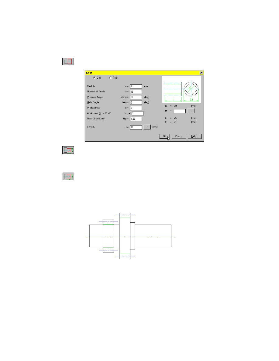
4
Choose the gear button, and enter the values for module, number of teeth
and length as shown in the following figure:
5
Choose the lower cylinder button to define another cylinder section, and
respond to the prompts as follows:
Specify length <10>:
Enter 4
Specify diameter <20>:
Enter 24
6
Choose the lower cylinder button to define another cylinder section, and
respond to the prompts as follows:
Specify length <4>:
Enter 33
Specify diameter <24>:
Enter 20
Now, you have created the first five sections of the shaft as represented in the
following figure:
212
|
Chapter 12
Creating Shafts With Standard Parts
Inserting Spline Profile
Now, you add a spline profile to the shaft.
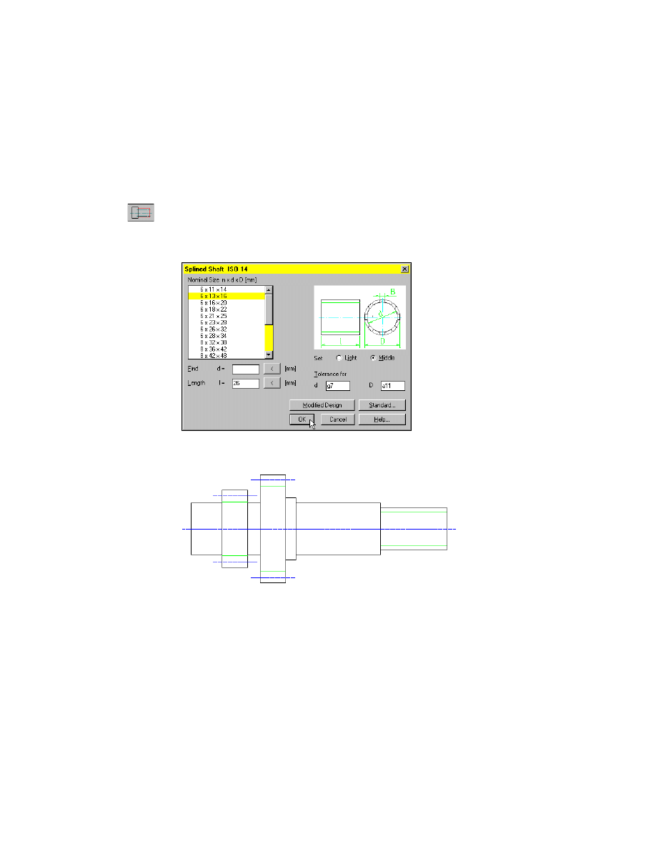
To create a profiled segment
1
Choose the Profile button.
2
Choose ISO 14 in the database browser.
3
In the Splined Shaft ISO 14 dialog box, select the standard size 6 x 13 x 16
and define a length of 26. Choose OK.
Now, you have created another section of the shaft as represented in the fol-
lowing figure:
Creating Shafts with Standard Parts
|
213
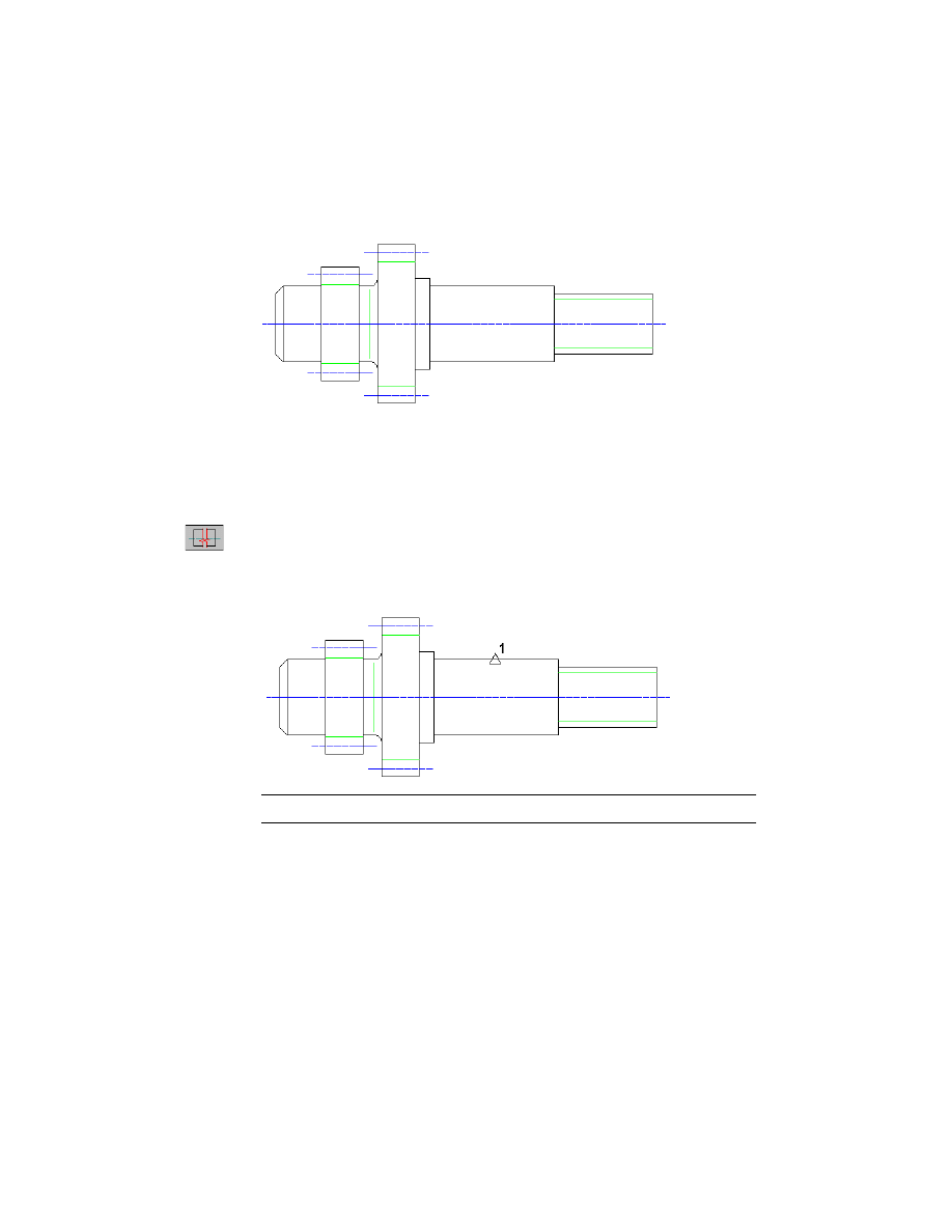
Inserting Chamfer and Fillet
In this step, you apply a chamfer and a fillet to the shaft.
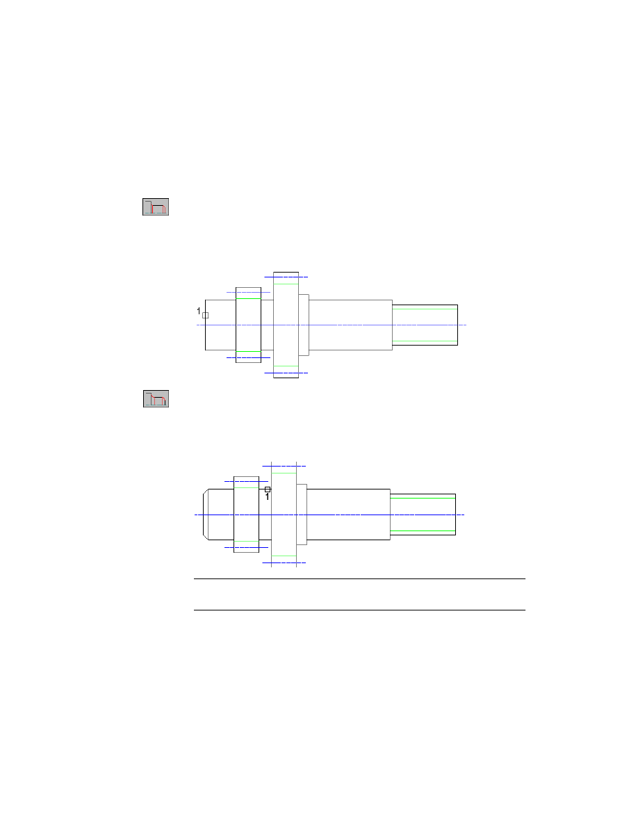
To apply a chamfer and a fillet
1
Choose the Chamfer button to apply a chamfer to a shaft section, and
respond to the prompts as follows:
Select object:
Select the leftmost cylinder section (1)
Specify length (max. 12) <2.5>:
Enter 2
Specify angle (0-79) or [Distance] <45>:
Enter 45
2
Choose the Fillet button to apply a fillet to a shaft section, and respond to
the prompts as follows:
Select object:
Select the cylinder section between the two gears near the second
gear (1)
Enter radius (max. 5.00) <2.50>:
Enter 2
NOTE
The fillet will be applied to the edge of the selected section, which is
closer to the selected point on the section.
214
|
Chapter 12
Creating Shafts With Standard Parts
After applying the chamfer and the fillet, the shaft looks like the following
figure:
Inserting Shaft Breaks
Here, you insert a shaft break in the drawing.
To insert a shaft break
1
Choose the Break button to insert a shaft break, and respond to the prompts
as follows:
Specify point:
Select the midpoint of the cylindrical section (1)
Specify length (min. 4.00) <6>:
Enter 10
NOTE
You can insert the break to the left, if you enter a negative value.
Creating Shafts with Standard Parts
|
215
The shaft break is inserted.
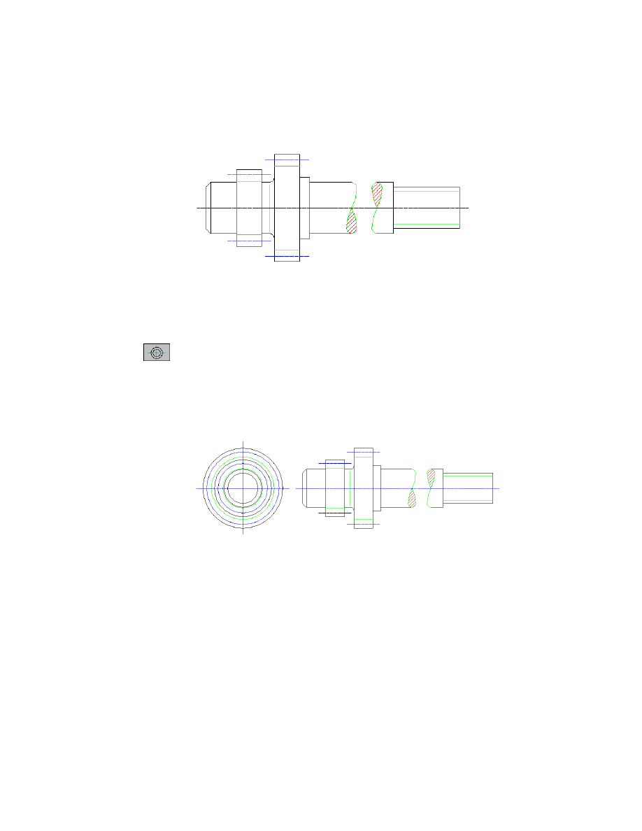
Creating Side Views of Shafts
Next, you insert a side view of the shaft.
To insert a side view
1
Choose the Side view button.
2
In the Side view from dialog box, select Right. Choose OK.
3
Respond to the prompt as follows:
Specify insertion point:
Press
ENTER
The right side view is inserted at the proposed position as shown in the
following figure:
216
|
Chapter 12
Creating Shafts With Standard Parts
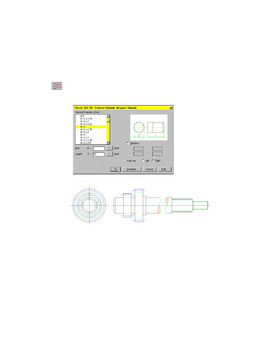
Inserting Threads on Shafts
Now, you add a thread to the shaft.
To insert a thread on a shaft
1
Choose the Thread button to insert a thread, and select ISO 261 in the
browser.
2
In the Thread ISO 261 dialog box, select M10 and enter a length of 20.
Choose OK.
The thread is added to the shaft, which looks like this now:
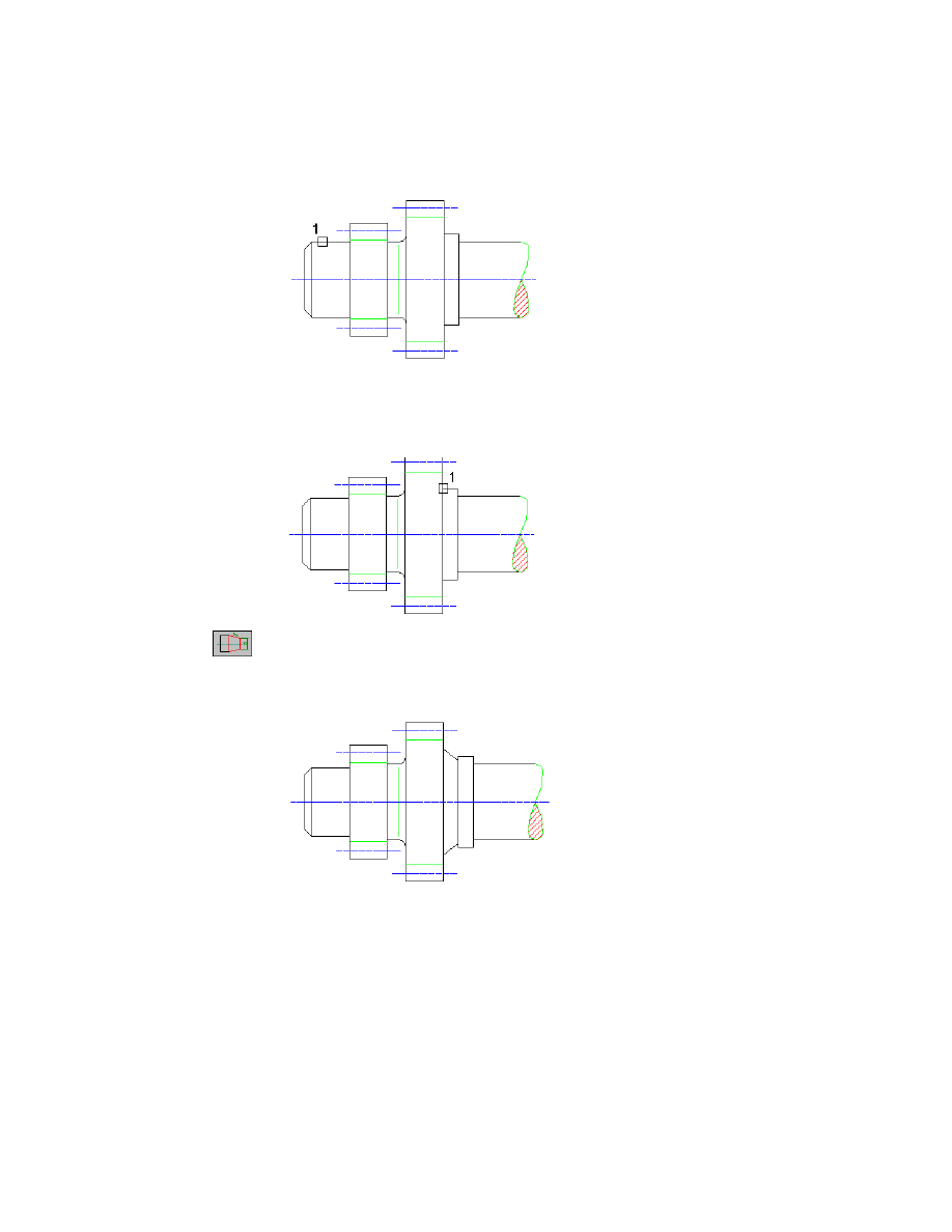
Editing Shafts and Inserting Sections
In this section, you edit an existing shaft section and insert a new section.
To edit and insert a shaft section
1
Choose the Edit button, and respond to the prompts as follows:
Select object:
Select the first cylindrical section (1)
Specify length <12>:
Press
ENTER
Specify diameter <20>:
Enter 18
Creating Shafts with Standard Parts
|
217
The diameter is changed to 18 while the length remains 12.
2
Choose the Insert button, and respond to the prompt as follows:
Specify point:
Select a point after the second gear (1)
3
Choose the Slope button, and respond to the prompts as follows:
Specify length or [Dialog] <20>:
Enter 4
Specify diameter at starting point <24>:
Enter 28
Specify diameter at endpoint or [Slope/Angle] <20>:
Enter 22
218
|
Chapter 12
Creating Shafts With Standard Parts
Replacing Shaft Sections
The previously inserted slope needs to be deleted again.
To replace a shaft section
1
Choose the Undo button.
The previous slope insertion is undone.
Now, replace an existing shaft section. To do this, you change the settings in
the configuration.
2
Choose the Config button to start the shaft generator configuration, and
specify:
For Segment inserted:
Overdraw
3
Choose OK.
4
Choose the Slope button, and respond to the prompt as follows:
Specify length or [Dialog] <4>:
Enter D
Creating Shafts with Standard Parts
|
219
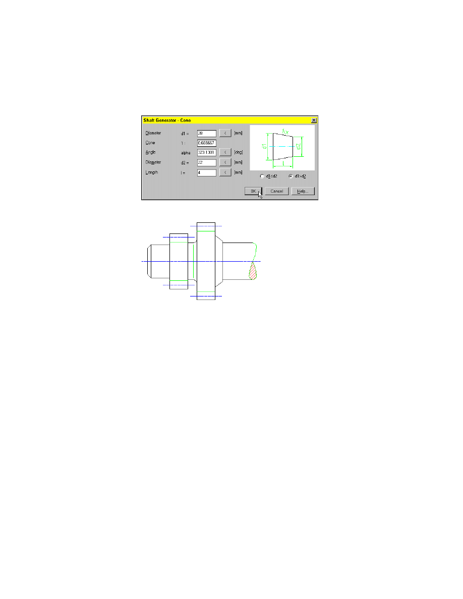
5
In the Shaft Generator - Cone dialog box, make the following settings and
choose OK.
The slope replaces the cylindrical shaft section.
Inserting Bearings
Here, you insert a bearing and perform a bearing calculation.
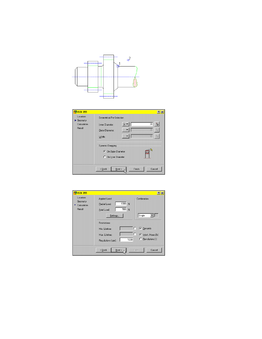
To insert a bearing
1
Choose the Standard Parts button, and select a radial roller bearing ISO 355
in the browser. Respond to the prompts as follows:
Specify insertion point on shaft contour:
Specify the insertion point (1)
Direction to [Left]:
Select a point to the right (2)
220
|
Chapter 12
Creating Shafts With Standard Parts
2
In the ISO 355 dialog box, choose Next >.
3
In the ISO 355 dialog box, specify the loads and activate Work Hours as
shown in the following, and choose Next >.
Creating Shafts with Standard Parts
|
221
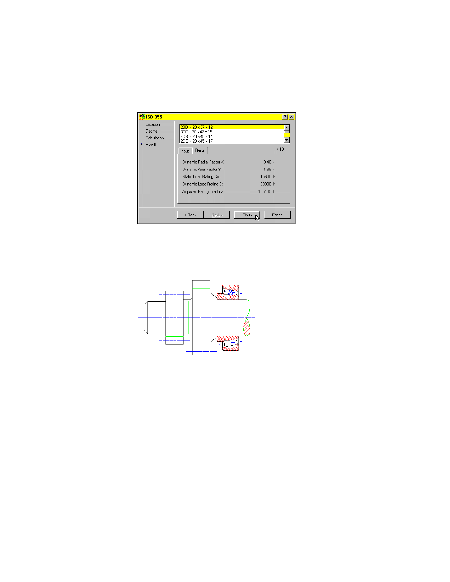
4
In the ISO 355 dialog box, select the bearing 2BD - 20 x 37 x 12, and choose
Finish.
The bearing is inserted, and you can select the available sizes by dragging.
5
Choose 2BD - 20 x 37 x 12 and press
ENTER
.
The bearing is inserted.
6
Choose Close.
This is the end of this tutorial chapter.
Save your file.

222
Wyszukiwarka
Podobne podstrony:
Ch22 Standard Parts
Ch10 Standard Parts
Ch12 Create Parts
Ch12 Create Parts
Think common parts with other cars
AUTOMATED SECURITY HARDENING OF RED HAT ENTERPRISE LINUX V5 IN ACCORDANCE WITH DISA STANDARDS CSC Pa
standard HL7
Metodologia SPSS Zastosowanie komputerów Golański Standaryzacja
standaryzacja w geomatyce
Wykł 1 Omówienie standardów
Złote standardy w diagnostyce chorób układowych 3
więcej podobnych podstron