
671
In This Chapter
22
Working with Standard
Parts
Standard parts is the term used for the vast selection of
real-world reusable 2D and 3D parts, holes, features, and
structural steel profiles that are available to you in
Autodesk
®
Mechanical Desktop
®
6 with the power pack.
These standard parts are provided in many different
base standards.
In this tutorial you select standard parts to insert
through holes on a 3D part, using two different
positioning methods. You also add a screw connection
to a 3D assembly model using standard parts.
Run Mechanical Desktop with the power pack to
perform this tutorial.
■
Selecting standard parts
■
Inserting holes using the cylinder
axial placement method
■
Inserting holes using the cylinder
radial placement method
■
Inserting a screw connection
■
Creating a drawing view with 2D
standard parts

672
|
Chapter 22
Working with Standard Parts
Key Terms
Term
Definition
base standard
Predefined drafting standard that conforms to International Drafting Standards
ANSI, BSI, CSN, DIN, GB, ISO, and JIS.
cylinder axial
Option for placement when you insert a standard part or hole parallel to a
cylinder axis.
cylinder radial
Option for placement when you insert a standard part or hole radial into a
cylinder.
hole
Geometric feature with a predefined shape: drilled, counterbore, or countersink.
parallel
Being an equal distance apart at every point.
standard part
Reusable 2D and 3D parts, holes, features, and structural steel profiles available in
Mechanical Desktop 6.
tangent
Touching at a single point or along a line, but not intersecting.
through
Termination method by which a feature extends from its sketch plane through the
part.

Tutorial at a Glance
|
673
Tutorial at a Glance
This tutorial is an introduction to the standard parts and calculations func-
tionality in Mechanical Desktop 6. You will become familiar with some of the
intelligence and automation built into this functionality as you perform
exercises to insert
■
A through hole using the cylinder axial placement method.
■
Through holes using the cylinder radial placement method.
■
A screw connection using the automated screw connection feature.
■
A standard related 2D-Representation of standard parts.
Basic Concepts of Standard Parts
A large selection of standard parts are made available to you in Mechanical
Desktop 6. These standard parts are provided in many different base stan-
dards. You make your selections from lists of standard parts as you work. For
example, when you select a screw, you can choose from different types of
screws and from different configurations of threads. Using the standard parts
and calculations functionality, you can insert complete screw connections
including screws, holes, and nuts in one automated process.
The software is intelligent, and prevents you from assembling parts that do
not fit. For example, if you select a screw with a metric thread, only metric
threads are added with any additional parts or features, such as threaded
holes or nuts. If you select screws, holes, and nuts from varying standards,
the software determines if those parts will work together.
674
|
Chapter 22
Working with Standard Parts
Inserting Through Holes
It is no longer necessary to insert a workpoint on the cylinder face,
dimension it, and insert a hole on the workpoint. Instead, the standard hole
function automatically defines a workpoint at the location you select,
dimensions it, and places the hole you specify. You can also define the inser-
tion point dynamically.
Using Cylinder Axial Placement
In this exercise, you insert a standard through hole using the cylinder axial
placement method. Use this method to insert holes parallel to the axis of a
cylinder. You enter specifications and select a size from a list of standard
holes, and the hole is inserted automatically.
Open the file md_ex01.dwg in the desktop\tutorial folder.
NOTE
Back up the tutorial drawing files so you still have the original files if you
make a mistake. See “Backing up Tutorial Drawing Files” on page 40.
Inserting Through Holes
|
675
To insert a hole using cylinder axial placement
1
Use
AMTHOLE3D
to define the hole to insert.
Menu
Content 3D ➤ Holes ➤ Through Holes
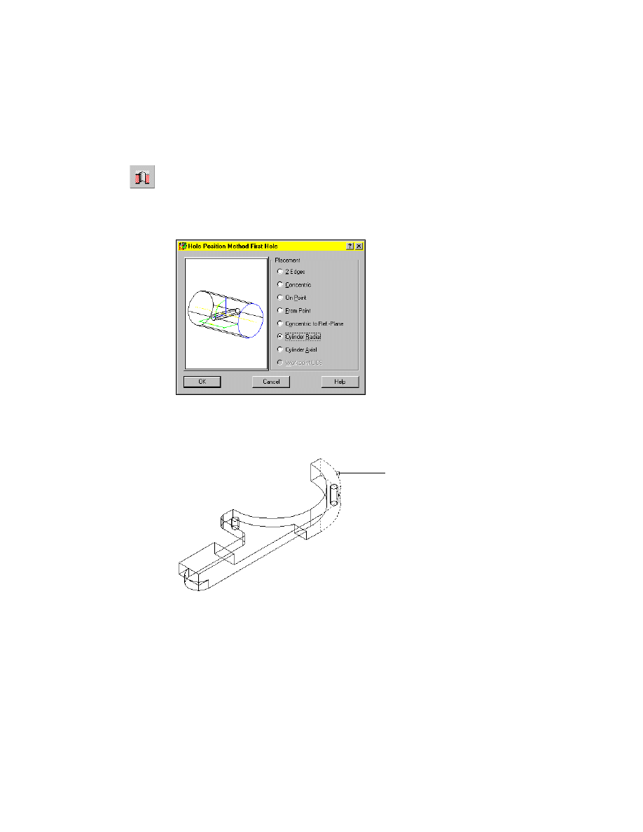
In the Select a Through Hole dialog box, select ISO 273 normal.
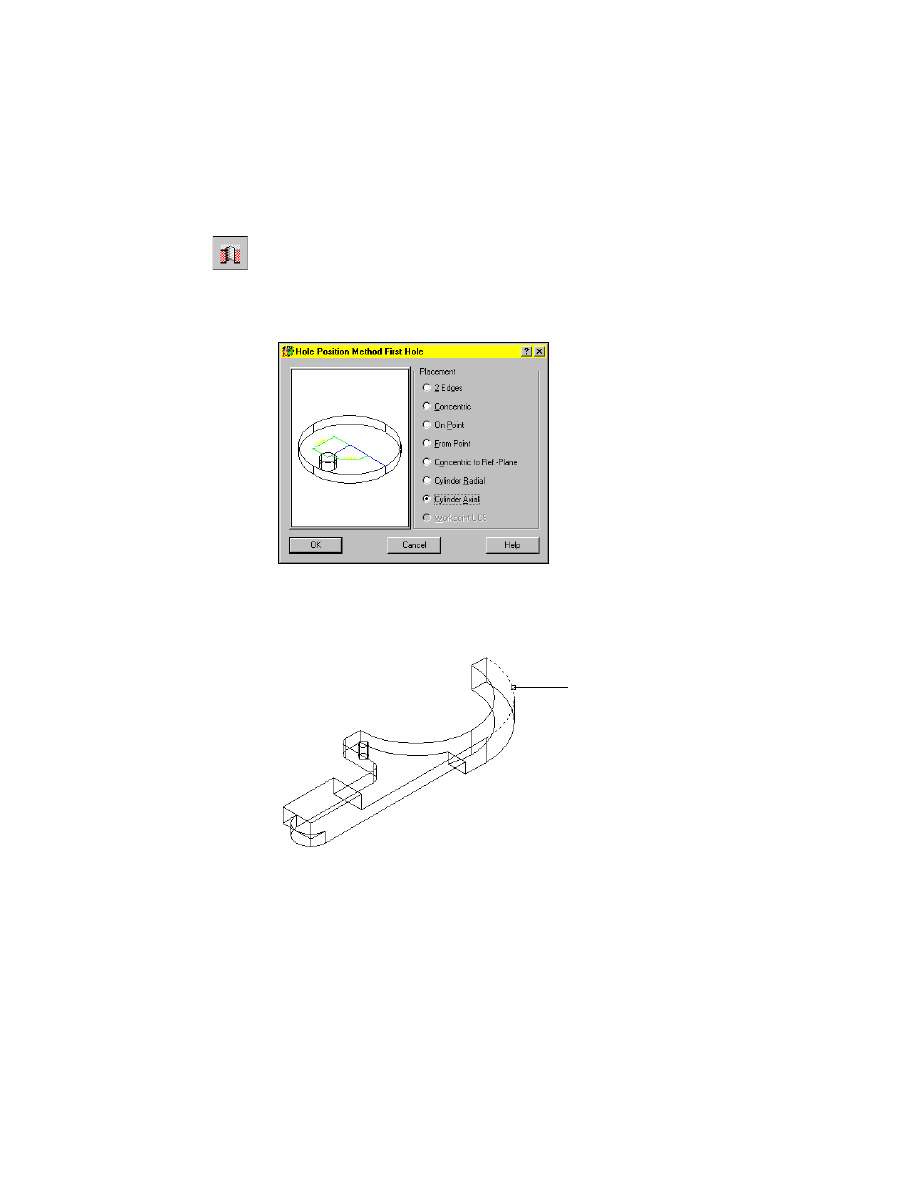
2
In the Hole Position Method First Hole dialog box, specify:
Placement:
Cylinder Axial
Choose OK.
3
On the command line, respond to the prompts as follows:
Select circular edge:
Select the upper circular edge (1)
1
676
|
Chapter 22
Working with Standard Parts
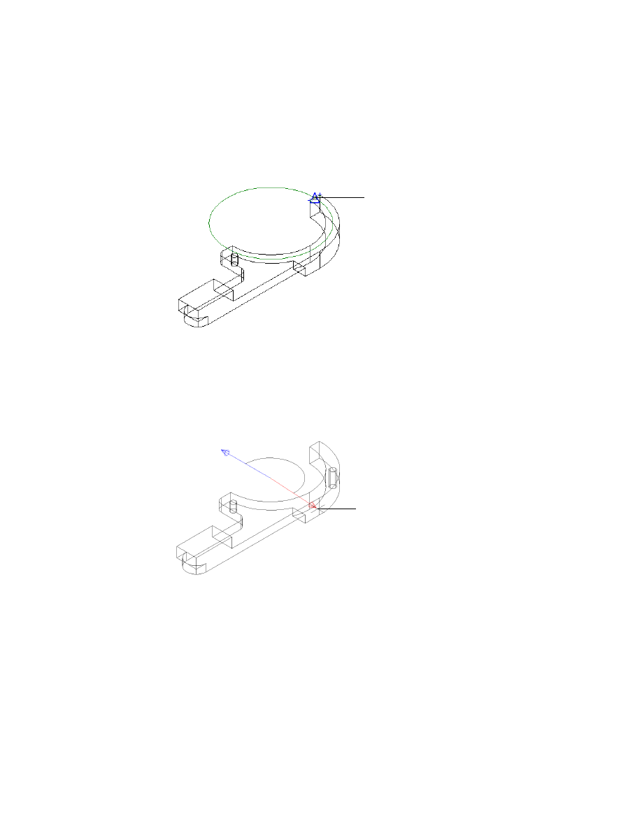
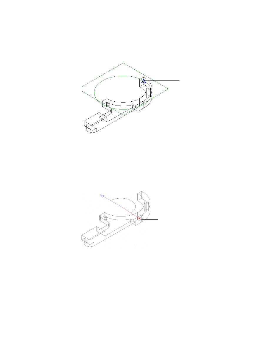
4
Continue on the command line.
Select radius:
Press SHIFT and in the graphics area, right-click and choose Midpoint
5
Select the midpoint of the upper horizontal edge (2).
6
Continue on the command line.
Select insertion method
[Angle to plane or edge/parallel to Line/plane Normal/plane Parallel] <plane
Parallel>:
Enter A
Select straight edge, work plane or planar face to add angular constraint
to:
Press
ENTER
Select angle:
Select an angle of approximately 135° (3)
Enter angle [Associate to/Equation assistant] <145>:
Enter 135
Radius [Associate to/Equation assistant] <90>:
Press
ENTER
Hole termination [toPlane/Thru] <Thru>:
Press
ENTER
2
3
Inserting Through Holes
|
677
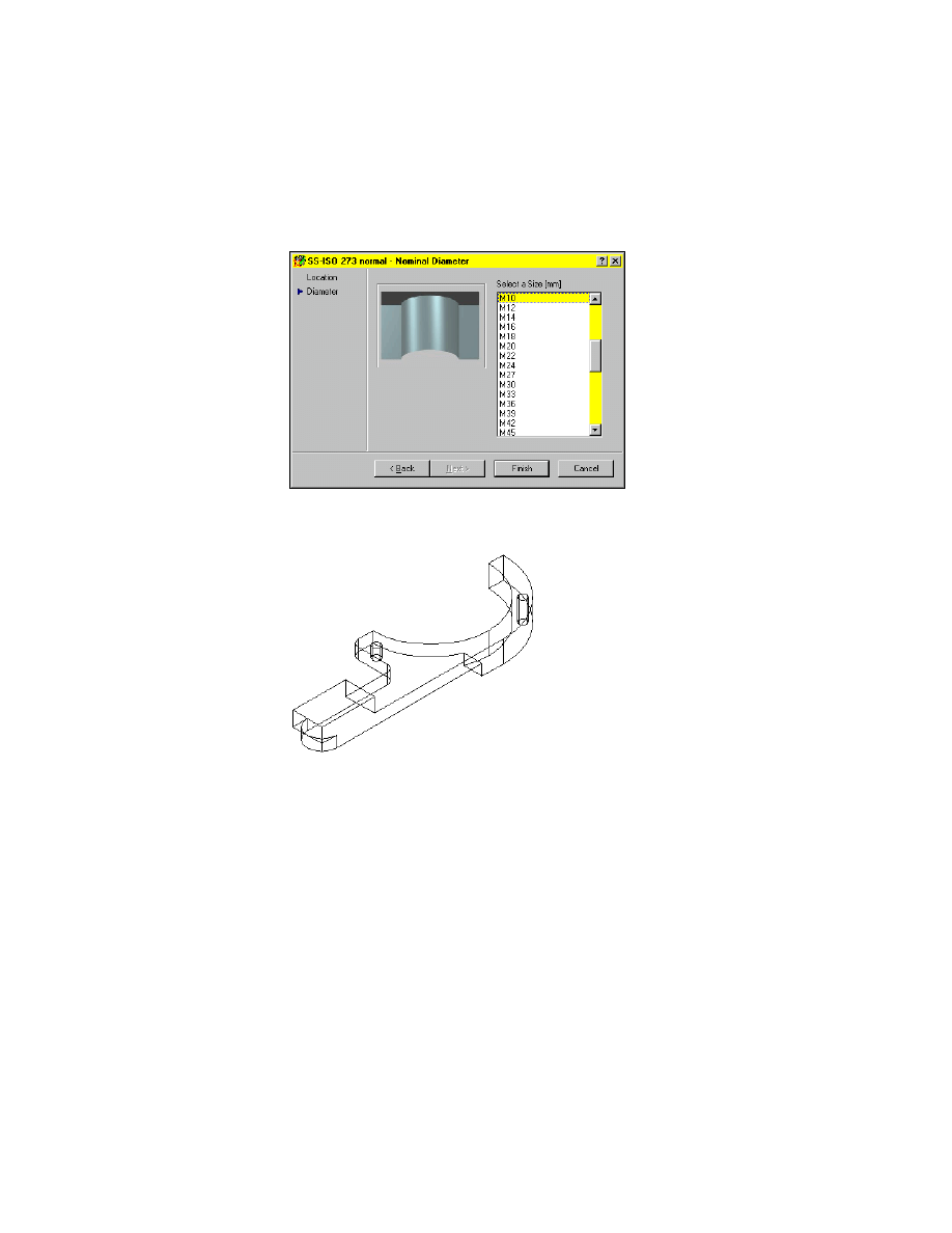
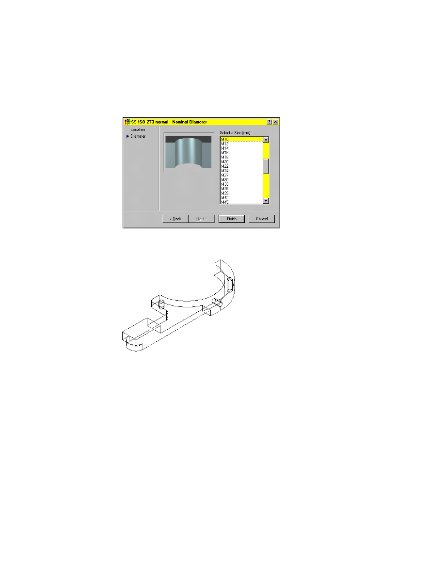
7
In the ISO 273 normal - Nominal Diameter dialog box, specify:
Select a size:
M10
Choose Finish.
The through hole is inserted in the size and location you selected.
Save the file as md2_ex01a.dwg.
Using Cylinder Radial Placement
In this exercise, you insert a through hole using the cylinder radial method.
Use this method to insert holes radial to a cylinder face.
678
|
Chapter 22
Working with Standard Parts
To insert a hole using cylinder radial placement
1
Use
AMTHOLE3D
to define the hole to insert.
Menu
Content 3D ➤ Holes ➤ Through Holes
In the Select a Through Hole dialog box, select ISO 273 normal.
2
In the Hole Position Method First Hole dialog box, specify:
Placement:
Cylinder Radial
Choose OK.
3
On the command line, respond to the prompts as follows:
Select cylindrical face:
Select the upper cylindrical face (1)
Continue on the command line.
Specify hole location [Line/Plane]:
Press SHIFT and in the graphics area, right-click and choose Midpoint
1
Inserting Through Holes
|
679
4
Select the midpoint of the upper vertical edge (2).
5
Respond to the prompts as follows:
Enter distance from base plane [Associate to/Equation assistant] <15>:
Press
ENTER
Select drill direction
[Angle to plane or edge/parallel to Line/plane Normal/plane Parallel]
<plane Parallel>:
Enter A
Select straight edge, work plane or planar face to add angular constraint to:
Press
ENTER
Select angle:
Select an angle of approximately 180° (3)
Continue on the command line:
Enter angle [Associate to/Equation assistant] <181>:
Enter 180
Hole termination [toPlane/Thru] <Thru>:
Press
ENTER
2
3
680
|
Chapter 22
Working with Standard Parts
6
In the ISO 273 normal - Nominal Diameter dialog box, specify:
Select a size:
M10
Choose Finish.
The through hole is inserted. Your drawing should look like this:
Save the file as md2_ex01b.dwg.
Inserting Screw Connections
|
681
Inserting Screw Connections
In this exercise, you begin with a drawing of two parts that need a screw con-
nection. Using the screw connection feature, you select the screw, holes, and
nut that you want to use.
You define the size of the screw in a dialog box. Then you insert the screw
connection in the assembly. With this method, there is no need to create two
separate holes before you insert the screw with the nut. The screw connec-
tion function does this for you automatically.
Open the file md_ex02 in the desktop\tutorial folder.
NOTE
Back up the tutorial drawing files so you still have the original files if you
make a mistake. See “Backing up Tutorial Drawing Files” on page 40.
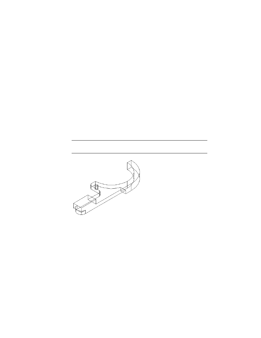
The drawing contains two parts of a housing.
682
|
Chapter 22
Working with Standard Parts
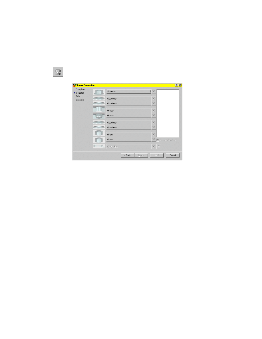
To insert a screw connection
1
Use
AMSCREWCON3D
to choose and define the screw to insert.
Menu
Content 3D ➤ Screw Connection
In the Screw Connection dialog box, select Screws.
Next, define the type of screw.
Inserting Screw Connections
|
683
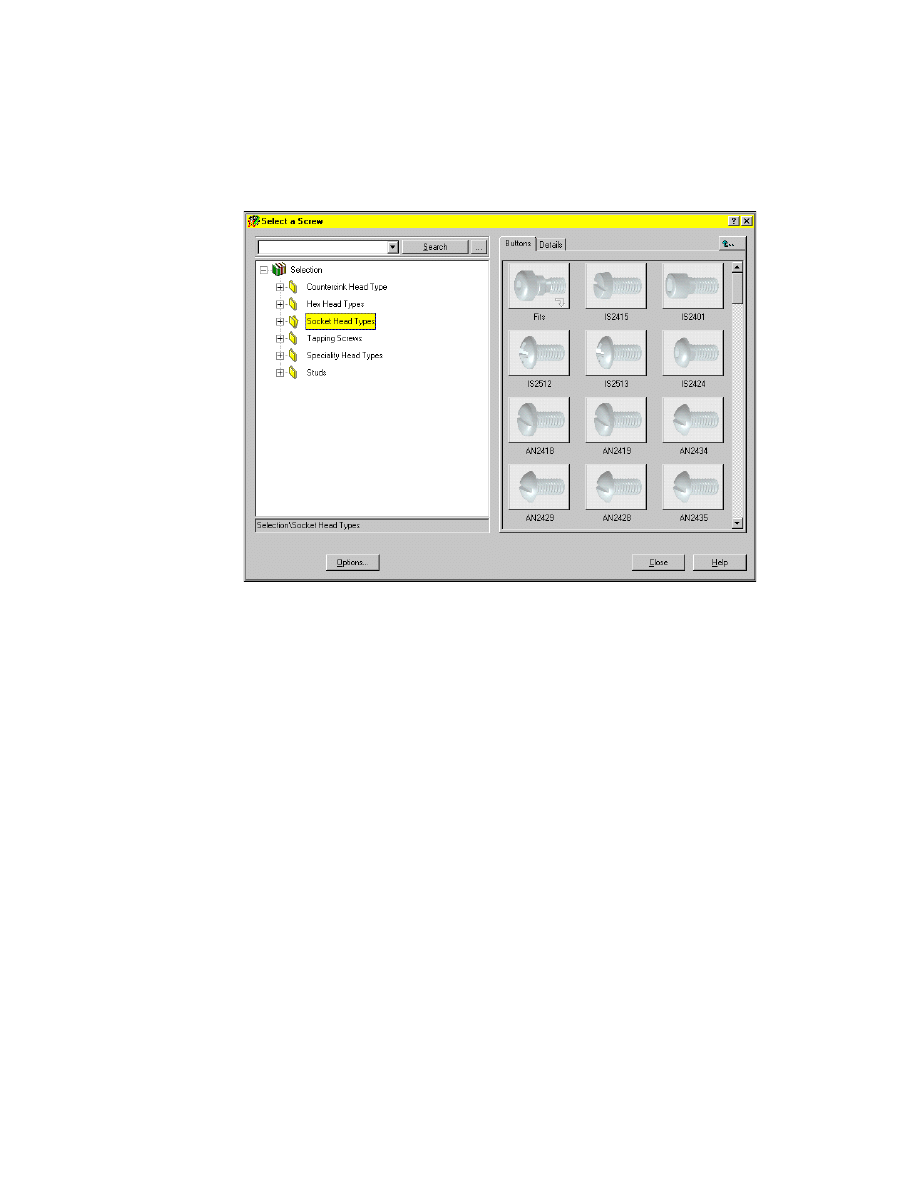
2
In the Please select a Screw dialog box, select Socket Head Types.
Select the screw IS2401.
The Screw Connection dialog box is displayed again.
3
Repeat steps 1 and 2 to select and define each of the following parts:
Hole ➤ Through Cylindrical ➤ IS1602 normal
Hole ➤ Through Cylindrical ➤ IS1602 normal
Nut ➤ Hex Nuts ➤ ISO842
After you select and define the parts for the screw connection, select a size for
the diameter.
684
|
Chapter 22
Working with Standard Parts
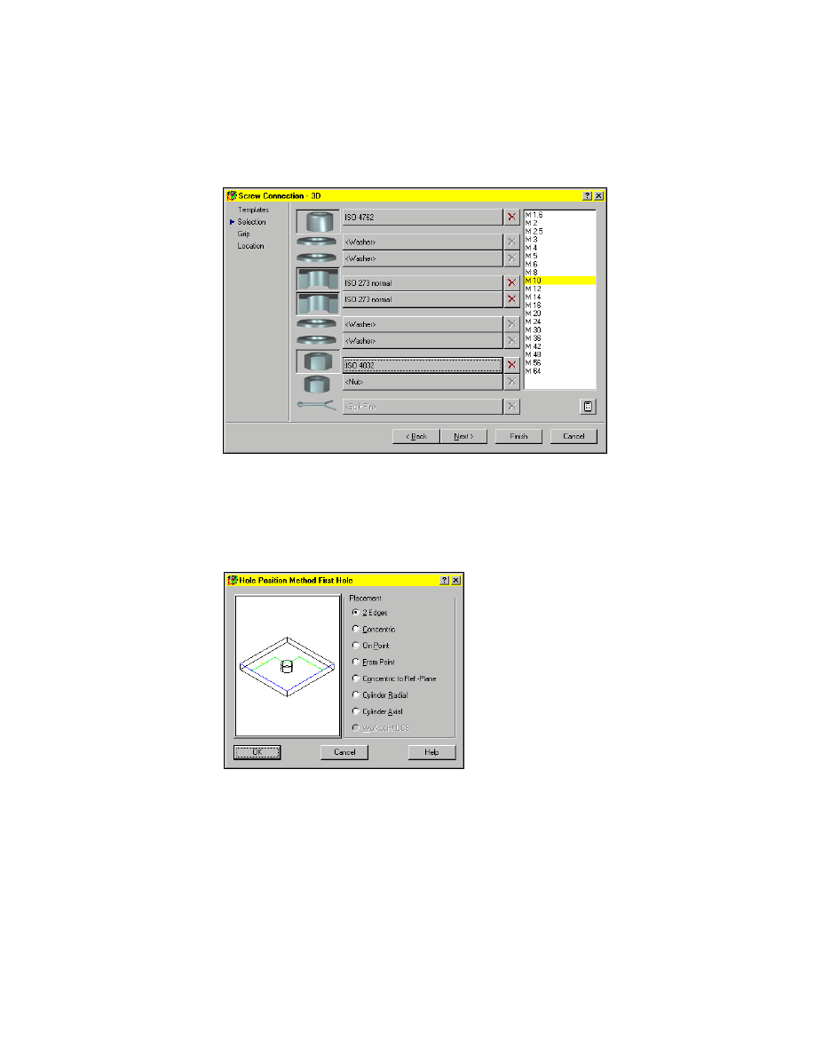
4
Select M10 for the diameter.
Choose Finish.
The Hole Position Method First Hole dialog box is displayed.
5
In the Hole Position Method First Hole dialog box, specify the hole position-
ing method as follows:
Placement:
2 Edges
Choose OK.
Inserting Screw Connections
|
685
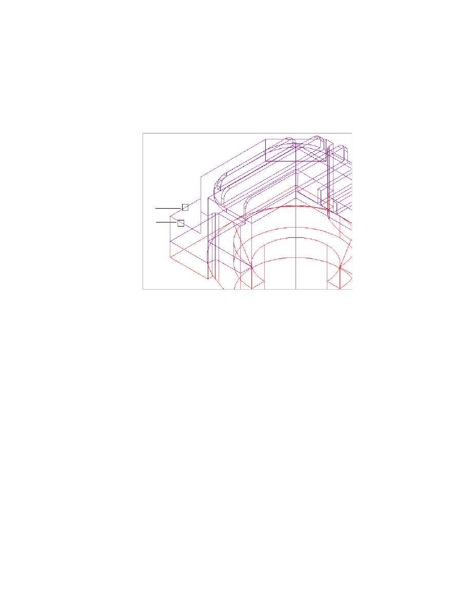
6
On the command line, respond to the prompts as follows:
Select first edge or planar face:
Specify the first edge (1)
Select second edge or planar face:
Specify the second edge (2)
Continue on the command line.
Specify the hole location: Specify a point on the face, offset from the two edges
Enter distance from first geometry (highlighted) [Associate to/Equation assistant]
<15.06>:
Enter 20
Enter distance from second geometry (highlighted) [Associate to/Equation
assistant] <23.05>:
Enter 20
Hole termination [toPlane/Thru] <Thru>:
Press
ENTER
1
2
686
|
Chapter 22
Working with Standard Parts
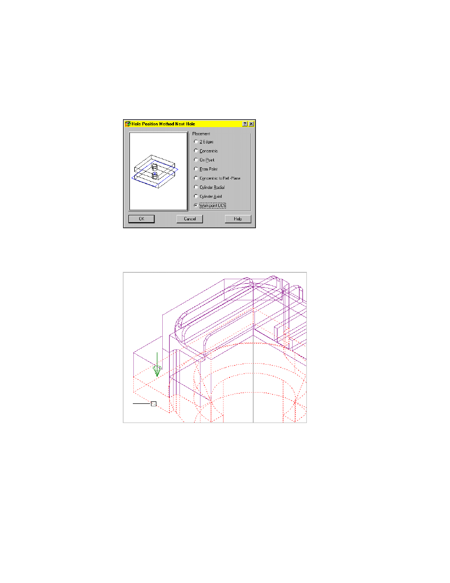
7
In the Hole Position Method Next Hole dialog box, specify:
Placement:
Workpoint UCS
Choose OK.
8
Respond to the prompt as follows:
Select next part to drill through:
Select the lower part (3)
Continue on the command line:
Hole termination [toPlane/Thru] <Thru>:
Press
ENTER
3
Inserting Screw Connections
|
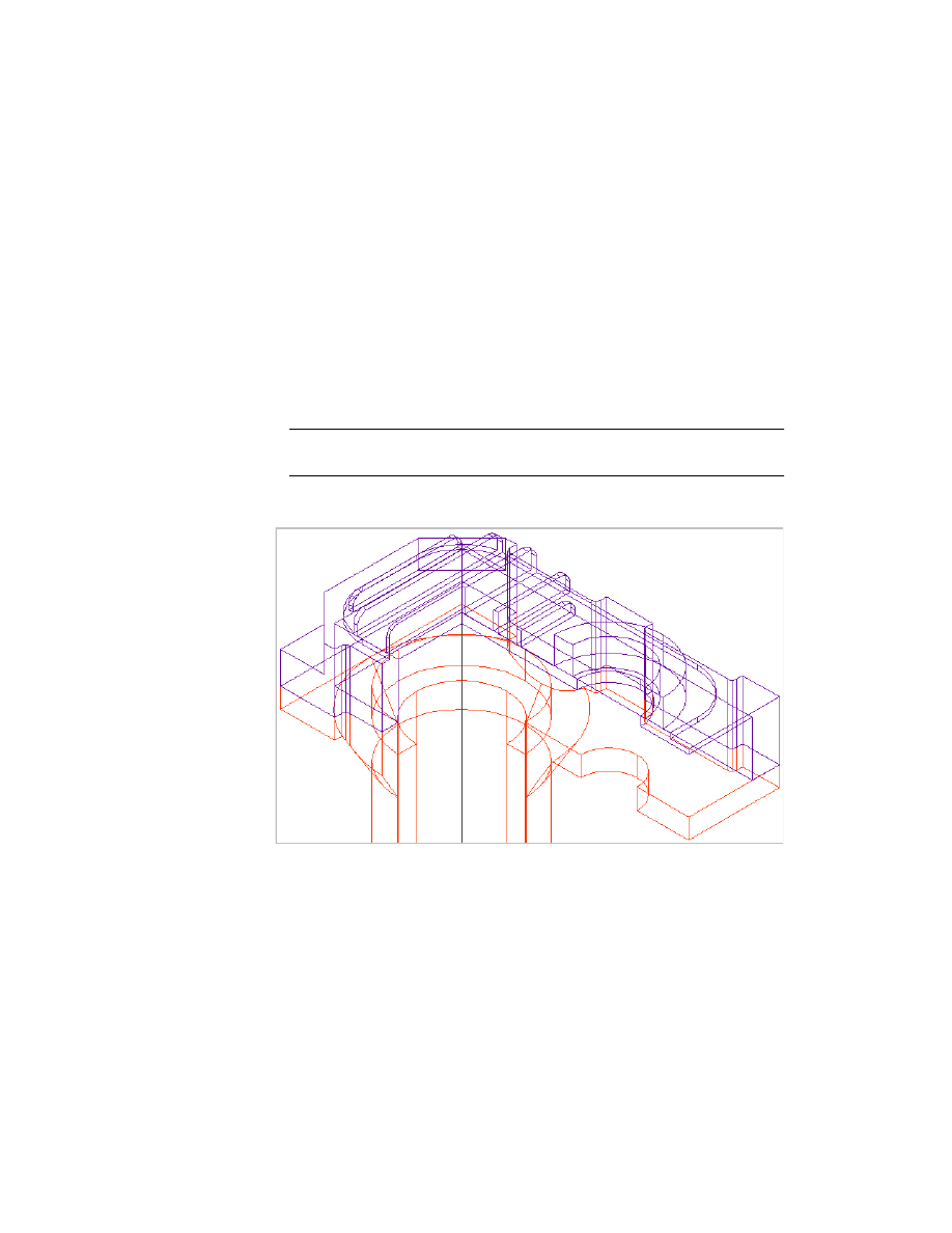
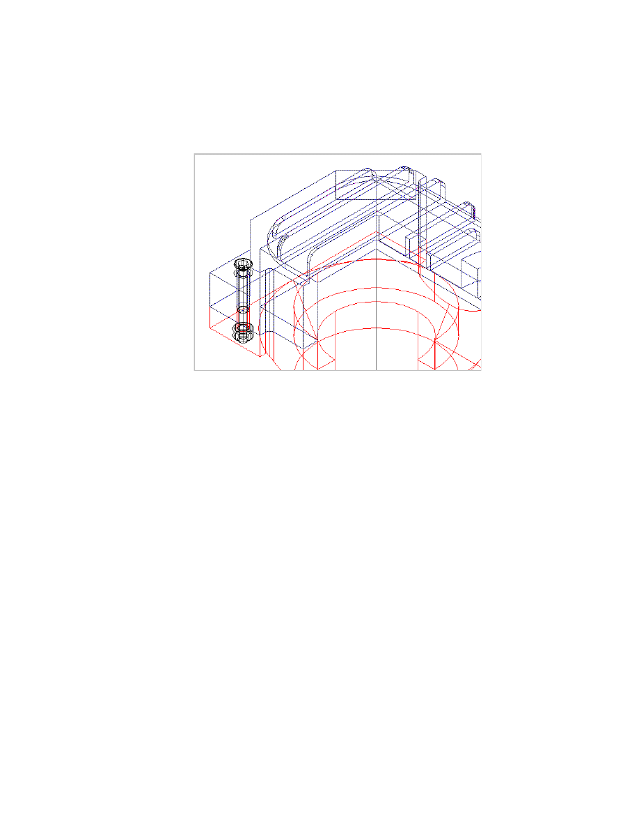
687
The screw connection is inserted. Your drawing should look like this:
You have completed this tutorial.
Save the file as md6_ex17b.dwg.

688
Wyszukiwarka
Podobne podstrony:
Ch12 Shafts with Standard Parts
Ch10 Standard Parts
Ch12 Shafts with Standard Parts
standard HL7
Metodologia SPSS Zastosowanie komputerów Golański Standaryzacja
standaryzacja w geomatyce
Wykł 1 Omówienie standardów
Złote standardy w diagnostyce chorób układowych 3
Wyklad 2 zmiennosc standaryzacja 5 III 2014 b
01 standaryzacja IIIrokid 2944 ppt
Wyk 2 standardy pomiarów
Okidata Okipage 14e Parts Manual
więcej podobnych podstron