QUS40-096.B01 Page 1 of 3
Technical enquiries email: sales@murata-ps.com, tel:
+1 508 339 3000
www.murata-ps.com
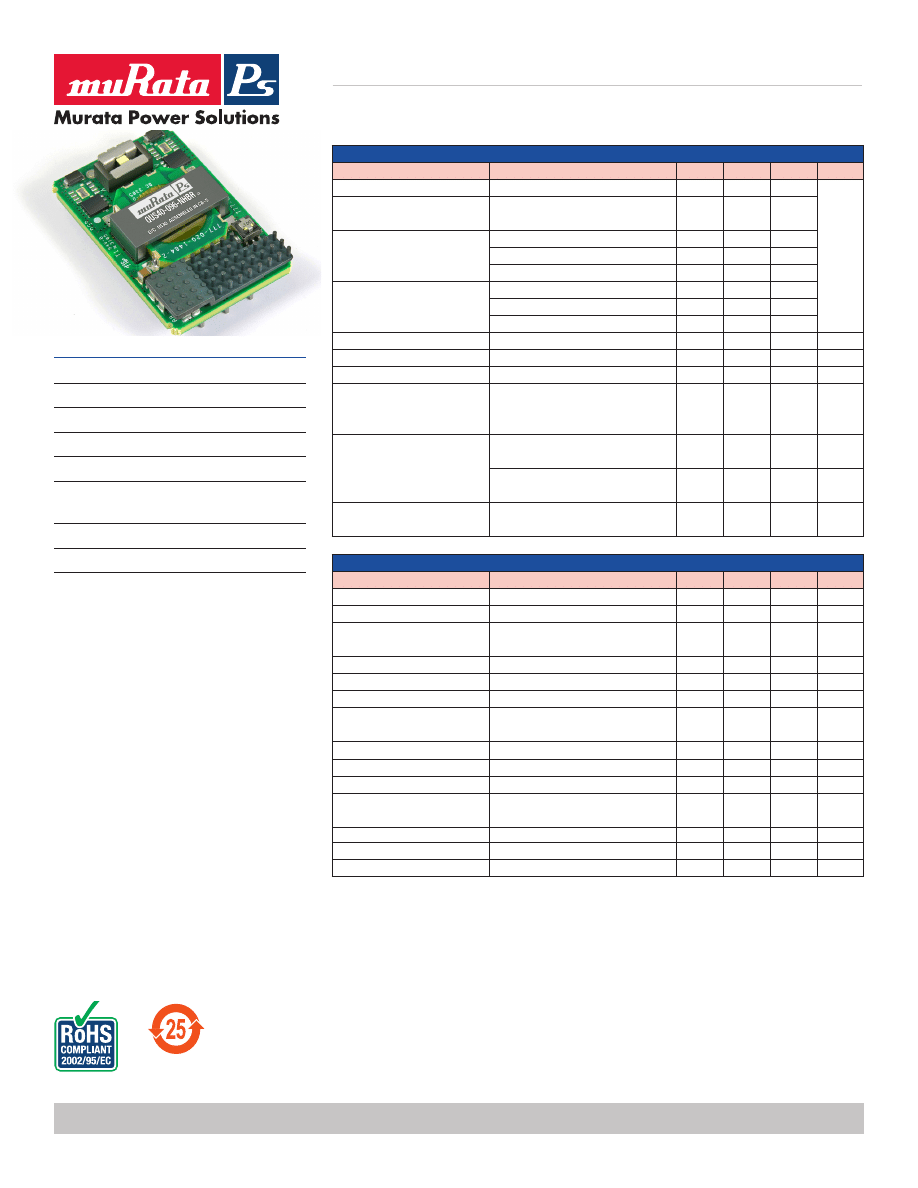
QUS40-096
Isolated Bus Converter
For full details go to
www.murata-ps.com/rohs
FEATURES
n
RoHS compliant
n
48 V
IN
, Isolated, 5:1 fixed conversion ratio
n
385W power at 48V
IN
n
300W output at 38 V
IN
, 55ºC, 200 LFM
n
Industry standard ¼ brick footprint
n
Remote enable (primary side, positive or
negative)
n
Over-temperature, over current protections
n
Direct parallel operation for higher power
DESCRIPTION
The QUS40-096 is a RoHS compliant fixed 5:1
ratio bus converter in an industry standard
quarter brick footprint to support Intermediate
Bus Architecture (IBA) for powering multiple
downstream non-isolated point-of-load (POL)
converters. The output is unregulated and the 5:1
fixed ratio is maintained between the input and
output voltages. It features input voltage range of
38V to 55V, and provides up to 384W @ 48Vin of
power or 300W at 38Vin @ 55ºC, typical efficiency
of 9.6V module is 96.6%. It can be parallel for
more power.
INPUT CHARACTERISTICS
Parameter
Conditions
1
Min.
Typ.
Max.
Units
Input voltage operating range
38
48
55
V
DC
Input voltage absolute
maximum
60
Input undervoltage lockout
Turn-on threshold
34
35.5
36
Turn-off threshold
32
33.5
34
Hysteresis voltage
2
Input overvoltage lockout
Turn-on threshold
55
58
Turn-off threshold
57
58.5
59.5
Hysteresis voltage
2
Maximum input current
Steady-state (40 A
OUT
)
8.4
9
A
DC
No-load input current
Enabled state, no load (48V
IN
)
100
mA
Disabled input current
Disabled state (48V
IN
)
7
mA
Input reflected ripple current
Measured into the input pin
Input capacitor 47µF type
Nichicon UPM1J470MPH or equivalant
300
mA rms
Enable - negative logic version
Internal 27.4KΩ
pulled-up to internal 5.0V
On state range
-0.1
0.8
V
DC
Off state range
2.4
15.0
V
DC
Resistance from enable pin
to -V
IN
With +V
IN
pin open, or tired to -V
IN
16.12
KΩ
OUTPUT CHARACTERISTICS
Parameter
Conditions
1
Min.
Typ.
Max.
Units
Output voltage set point
V
IN
= 48V, I
O
= 0A
9.40
9.50
9.60
V
DC
Output load regulation
I
O
= 0 to 40A
0.35
V
Output voltage total regulation
V
IN
= 38 to 55V, P
O
= 0 to 300W,
Ta = 55ºC
7.0
11.0
V
DC
Output ripple & noise
2
20MHz bandwidth
80
150
mV p-p
Output current operating range
Corresponding to P
O
= 300W
0
42
A
Efficiency
V
IN
= 48V, P
O
= 300W
96.6
%
Turn-on delay
From enable, <0.8V to V
O
> 10%
for V
IN
= 38V - 55V
0.5
10
ms
Output voltage rise time
3
From 10% to 90%
12
15
ms
Start-up inhibit time
Enabled: V
IN
applied to 90% V
OUT
140
ms
Transient response
3
25% step, 1A/µs, C
o
=1200µF
220
350
%V
O
Current sharing accuracy
(up to 3 in parallel)
At P
O
= 300W
5
10
%
Output turn on overshoot
0
350
mV
Output turn off undershoot
0
350
mV
Maximum output capacitance
3750
µF
1 V
IN
= 48Vdc, Ta = 25ºC, Airflow = 200LFM for all data unless otherwise noted.
2 Output Ripple Voltage and noise is specified when measured with a 10µF tantalum and a 1uF ceramic capacitor at the output pins.
3 During output voltage rise time (15ms Max.), output power shall be limited to 50% constant power.
Transient response is specified with a 960µF capacitor at the output of the converter.
QUS40-096.B01 Page 2 of 3
Technical enquiries email: sales@murata-ps.com, tel:
+1 508 339 3000
www.murata-ps.com
QUS40-096
Isolated Bus Converter
PROTECTION CHARACTERISTICS
Parameter
Conditions
1
Min.
Typ.
Max.
Units
Output over-current shutdown
2
Auto-restart
44
48
50
A
Restart rate
80
ms
Over temperature shutdown
3
Auto-restart
135
140
ºC
Over temperature restart hysteresis
10
ºC
GENERAL CHARACTERISTICS
Parameter
Conditions
Min.
Typ.
Max.
Units
Isolation voltage
Input to output
2250
V
DC
Isolation resistance
Input to output
10
MΩ
Storage temperature range
Non-condensing
-40
125
ºC
Operating temperature range
-40
85
ºC
Operating humidity
Non-condensing
10
90
%
Thermal measurement location temperature
3
See mechanical drawing for location
130
ºC
Material flammability
UL 94V-0
MTBF
Calculated per Mil Spec 217 E, or Bellcore at Ta=30ºC
2
3.3
x10
6
Hrs
Demonstrated
1.3
x10
6
Hrs
STANDARDS COMPLIANCE
Standards
Conditions
4
UL/CSA 60950
Basic insulation
MANUFACTURING TESTING
n
Burn-in test
n
Parametric test
SAFETY CONSIDERATIONS
The QUS series of converters are certified to the standards and extent listed in the ‘Standards Compliance’ section in the table above. If this product is built into
information technology equipment, the installation must comply with the above standard. Even though the product is safety certified to operate without an input
fuse, it is recommended that an input fuse of 15A (max.) is used.
The output of the converter (Vo+/Vo-) is considered to remain within SELV limits when the input to the converter meets SELV or TNV-2 requirements. The
converters and materials meet UL 94V-0 flammability ratings.
RoHS COMPLIANCE
The QUS40-096 converter is in compliance with the European Union Directive 2002/95/EC (RoHS) with respect to the
following substances: lead (Pb), cadmium (Cd), mercury (Hg), hexavalent chromium, polybrominated biphenyls (PBB) and
polybrominated diphenyl ethers (PBDE).
For further information, please visit www.cd4power.com/rohs
1 V
IN
= 48Vdc, Ta = 25ºC, Airflow = 200LFM for all data unless otherwise noted.
2 Input transient: if input voltage increases by 5V in 1µs, output over-current shut-down shall not be triggered (tested with Max. load and Max. output capacitance).
3 Thermal shutdown is monitored at the Thermal Measurement Location (TML). See ‘Mechanical Information’ on page 3 for TML location.
4 See ‘Safety Considerations’ shown above.
Derating curves are conducted in a controlled environment. End application testing is required to ensure the Thermal Measurement Location temperature is below the maximum specified.
Recommended airflow direction is from pin 1 to pin 3, or 3 to 1 (transversal to the unit).
QUS40-096.B01 Page 3 of 3
Technical enquiries email: sales@murata-ps.com, tel:
+1 508 339 3000
www.murata-ps.com
QUS40-096
Isolated Bus Converter
Murata Power Solutions, Inc. makes no representation that the use of its products in the circuits described herein, or the use of other
technical information contained herein, will not infringe upon existing or future patent rights. The descriptions contained herein do not imply
the granting of licenses to make, use, or sell equipment constructed in accordance therewith. Specifications are subject to change without
notice.
© 2008 Murata Power Solutions, Inc.
USA:
Mansfield (MA), Tel: (508) 339-3000, email: sales@murata-ps.com
Canada: Toronto, Tel: (866) 740-1232, email: toronto@murata-ps.com
UK:
Milton Keynes, Tel: +44 (0)1908 615232, email: mk@murata-ps.com
France: Montigny Le Bretonneux, Tel: +33 (0)1 34 60 01 01, email: france@murata-ps.com
Germany: München, Tel: +49 (0)89-544334-0, email: munich@murata-ps.com
Japan:
Tokyo, Tel: 3-3779-1031, email: sales_tokyo@murata-ps.com
Osaka, Tel: 6-6354-2025, email: sales_osaka@murata-ps.com
Website: www.murata-ps.jp
China: Shanghai, Tel: +86 215 027 3678, email: shanghai@murata-ps.com
Guangzhou, Tel: +86 208 221 8066, email: guangzhou@murata-ps.com
Murata Power Solutions, Inc.
11 Cabot Boulevard, Mansfield, MA 02048-1151 U.S.A.
Tel: (508) 339-3000 (800) 233-2765 Fax: (508) 339-6356
www.murata-ps.com email: sales@murata-ps.com ISO 9001 REGISTERED
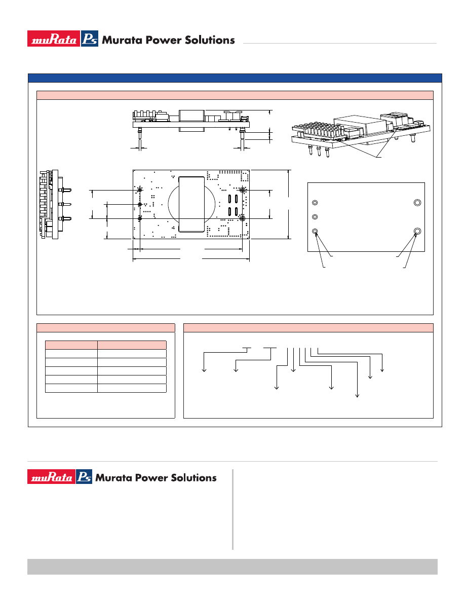
PACKAGE SPECIFICATIONS
MECHANICAL DIMENSIONS
PIN CONNECTIONS
ORDERING INFORMATION
Pin
Assignment
1
+V
IN
2*
ON/OFF
3
-V
IN
4
-V
OUT
5
+V
OUT
* Referenced to -V
IN
PIN #1
PIN #2
PIN #3
PIN #4
PIN #5
Bottom view
TML
Recommended
Footprint
1.45
(36.8)
0.600
(15.24)
0.300 (7.62)
0.600
(15.24)
2.000 (50.80)
0.43 (10.8)
0.14 (3.6)
2.28 (57.9)
(3X)
Ø0.040 ± 0.002 (1.02 ± 0.06)
(2X)
Ø0.062 ± 0.002 (1.57 ± 0.06)
y
Max.
0.480 (12.19)
Ø0.060 (1.52)
Ø0.105 (2.67)
Ø0.093 (2.36)
Ø0.137 (3.48)
Dimensions: 2.3 (58.4) L x 1.45 (36.83) W x 0.48 (12.19) H Max.
All dimensions in inches (mm).
Tolerance: X.X (X.XX) ±0.5 (0.2), X.XX (X.XXX) ±0.25 (0.010).
Max. 0.480 (12.19) between highest component and mounting plane.
Q U S x x - y y y - N H z R v C
O utput C urrent O utput voltage
h
t
g
n
e
L
n
i
P
ci
g
o
l
el
b
a
n
E
40 = 40A
096 = 9.6V
N = N egative logic
P = P ositive logic
B = 0.145''
C = 0.200''
Reserved
H orizontal M ount
C = R oH S C om pliant
Factory Internal Control Revision
(Not required when ordering)
04/22/2008
Wyszukiwarka
Podobne podstrony:
cdc eus34 096
07 2005 094 096
Aiwa CDC R136 (2)
P28 096
p08 096
61 096
Czym różni się skrzynia VW 095 od 096, automatyczne skrzynie
096 97
P16 096
cdc qus20 120
CDC PL
p34 096
pp 2009 096
ep 12 095 096
P18 096
096
cdc nfa016
więcej podobnych podstron