Technical enquiries email: sales@murata-ps.com, tel: +508 339 3000
1
NFA016_6200890000_B01_21/04/08
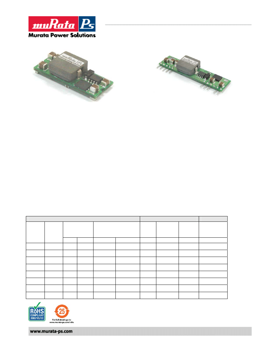
Non-Isolated 16A SIP/SMT DC/DC Converters
VOLANT NFA016 Series
Features:
9
Small size, minimal footprint – SMT/SIP package
9
16A Output Current (all voltages)
9
High Efficiency: up to 95%
9
High reliability
9
RoHS Compliant
9
Cost efficient open frame design
9
Output voltage programmable by an external resistor.
9
Monotonic Startup with Pre-Bias
9
+’ve Enable Logic and –‘ve Enable Logic models available
9
Optional Power Good Signal
9
Sequencing / Tracking Feature
Output
Input
Efficiency
PARD
(mVp-p)
Regulation
Max
Vin
Nom.
(V)
Range
(V)
Iin
Typ
(A)
Full Load
Vout
(V)
Iout
(A)
Typ. Max. Line
Load
Typ.
0.75
16
50
75
+/-0.2%
+/-0.5%
12
6.0 – 14
1.299
77%
1.2
16
50
75
+/-0.2%
+/-0.5%
12
6.0 – 14
1.928
83%
1.5
16
50
75
+/-0.2%
+/-0.5%
12
6.0 – 14
2.326
86%
1.8
16
50
75
+/-0.2%
+/-0.5%
12
6.0 – 14
2.727
88%
2.0
16
50
75
+/-0.2%
+/-0.5%
12
6.0 – 14
2.996
89%
2.5
16
50
75
+/-0.2%
+/-0.5%
12
6.0 – 14
3.704
90%
3.3
16
50
75
+/-0.2%
+/-0.5%
12
6.0 – 14
4.783
92%
5.0
16
50
75
+/-0.2%
+/-0.5%
12
6.5 – 14
7.092
94%
Murata Power Solutions
2
NFA016_6200890000_B01_21/04/08
Non-Isolated 16A SIP/SMT DC/DC Converters
VOLANT NFA016 Series
Input Characteristics
Notes & Conditions
Min
Typ.
Max
Units
Input Voltage Operating Range
Minimum 6.5 V input @ 5 volts output
6.0 12 14
Vdc
Input Reflected Ripple Current
200
mA p-p
Inrush Current Transient
0.2
A
2
s
Input Filter Type (external)
100
μF
Input Turn ON Threshold
5.0
V
Input Turn OFF Threshold
4.0
V
Positive enable: ON
open
Positive enable: OFF
<0.4
Vdc
Negative enable: ON;
open circuit or
<0.4
Vdc
Enable
(Positive enable has 20K pullup)
(Negative enable has no internal
pullup resistor)
Negative enable: OFF
2
Vin
Output Characteristics
Notes & Conditions
Min
Typ.
Max
Units
Vout Accuracy
100% load
-1.5
+1.5
%
Output Loading
0
16
A
Output Ripple & Noise
@ 20Mhz Bandwidth.
75
mVp-p
Maximum Capacitive Load
Low ESR
8000
μF
Vout Trim Range (Nom)
0.75
5.0
V
Total Accuracy
Over line/load temperature
<2%
Current Limit
23
A
Output Line Regulation
-0.2
+0.2
%
Output Load Regulation
-0.5
+0.5
%
Turn-on Overshoot
1
%
SC Protection Technique
Hiccup with auto recovery
Pre-bias Start-up at output
Unit starts monotonically with pre-
bias
Dynamic Characteristics
Notes & Conditions
Min
Typ.
Max
Units
Load Transient
50% step, 0.1A/
μs
100
mV
Settling
Time
200
μs
Operating Frequency
300
KHz
Rise Time
10% Vo to 90% Vo
3.5
ms
Start-Up Time
Vin to Vout and On/Off to Vout
7
ms
General Specifications
Notes & Conditions
Min
Typ.
Max
Units
MTBF Calculated
(MIL-HDBK-217F)
919.53
kHrs
Thermal Protection
Hotspot
110
°C
Operating Temperature
Without derating 300LFM
-40
50
°C
Operating Ambient Temperature
See Power derating curve
-40
85
°C
SIP Dimensions
2”Lx0.327”Wx0.512”H
(50.8x8.3x13.0mm)
SMT Dimensions
1.30”Lx0.53”Wx0.366”H
(33x13.46x9.3mm)
SIP Pin Dimensions
0.025” (0.64mm) SQUARE
0.64
mm
SMT Block Dimensions
0.063” x0.065” x 0.112”
SQUARE
Pin and Block Material
Matte Sn Finish on component
Leads
Flammability Rating
UL94V-0
Murata Power Solutions
3
NFA016_6200890000_B01_21/04/08
Non-Isolated 16A SIP/SMT DC/DC Converters
VOLANT NFA016 Series
Standards Compliance
CSA C22.2, No.60950/UL 60950, Third Edition (2000), File UL E165113
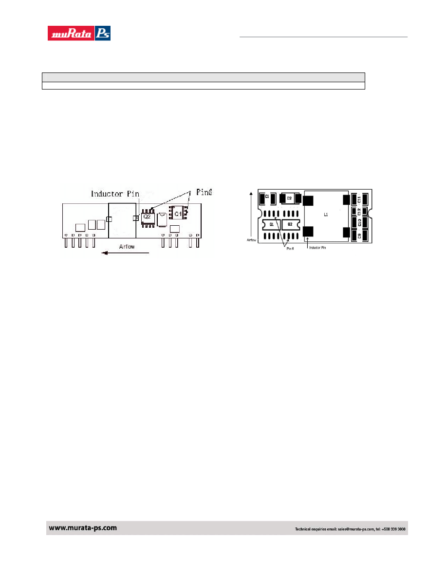
Thermal Considerations
The power module operates in a variety of thermal environments; however, sufficient cooling should
be provided to help ensure reliable operation of the unit.
The thermal data presented is based on measurements taken at various airflows. Note that airflow is
parallel to the long axis of the module as shown in Figure 1 and derating applies accordingly.
Figure 1. Thermal Tests Set-Up.
The temperature at either location should not exceed 110
°C. Over-temperature shutdown is
evaluated at these locations. The output power of the module should not exceed the rated power for
the module(Vo,set X Io,max).
Convection Requirements for Cooling
To predict the approximate cooling needed for the module, refer to the Power Derating Curves in
Figures 2-17 .
These derating curve are approximations of the ambient temperature and airflow required to keep the
power module temperature below it's maximum rating. Once the module is assembled in the actual
system, the module's temperature should be verified.
Murata Power Solutions
4
NFA016_6200890000_B01_21/04/08
Non-Isolated 16A SIP/SMT DC/DC Converters
VOLANT NFA016 Series
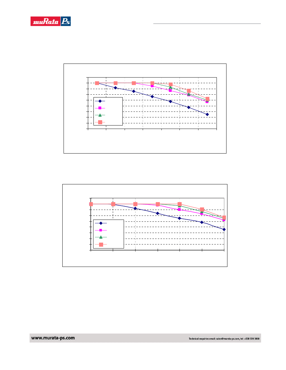
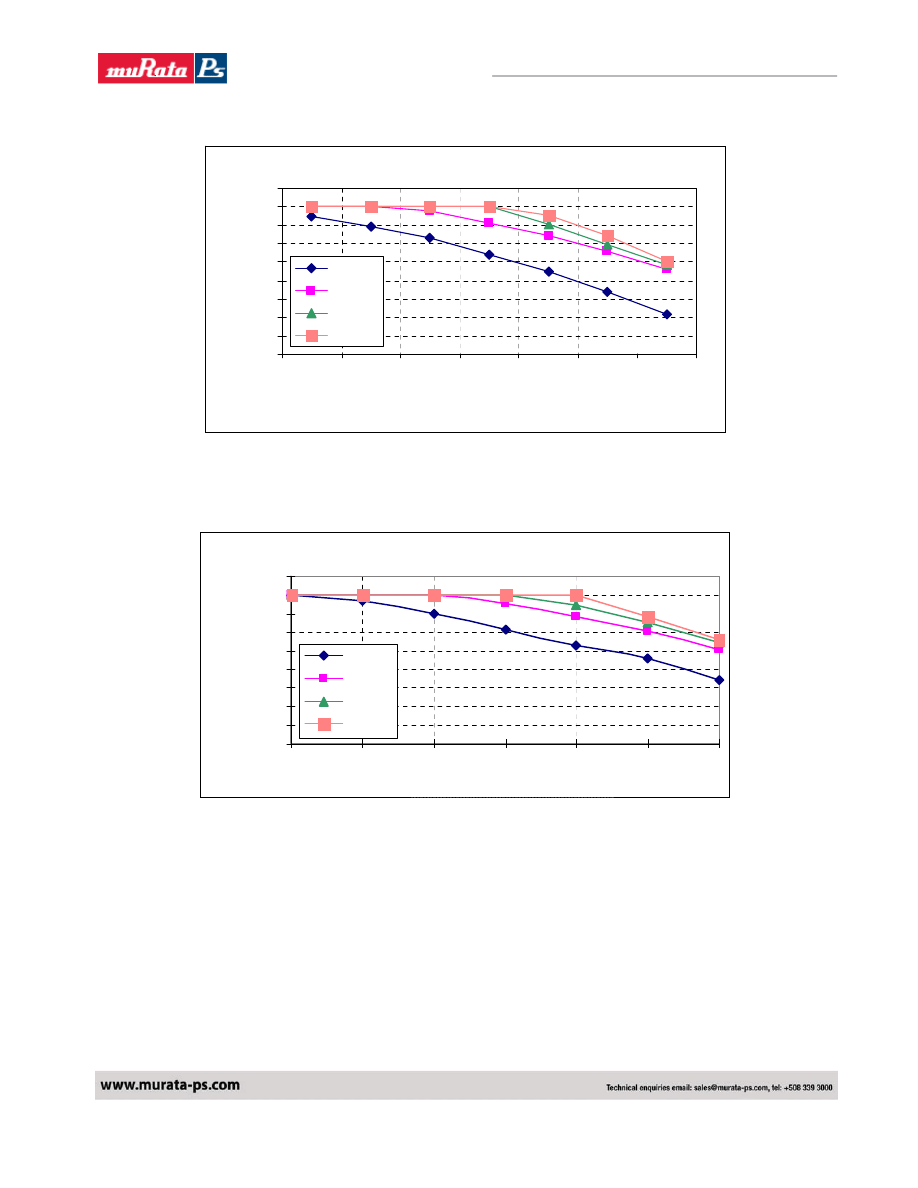
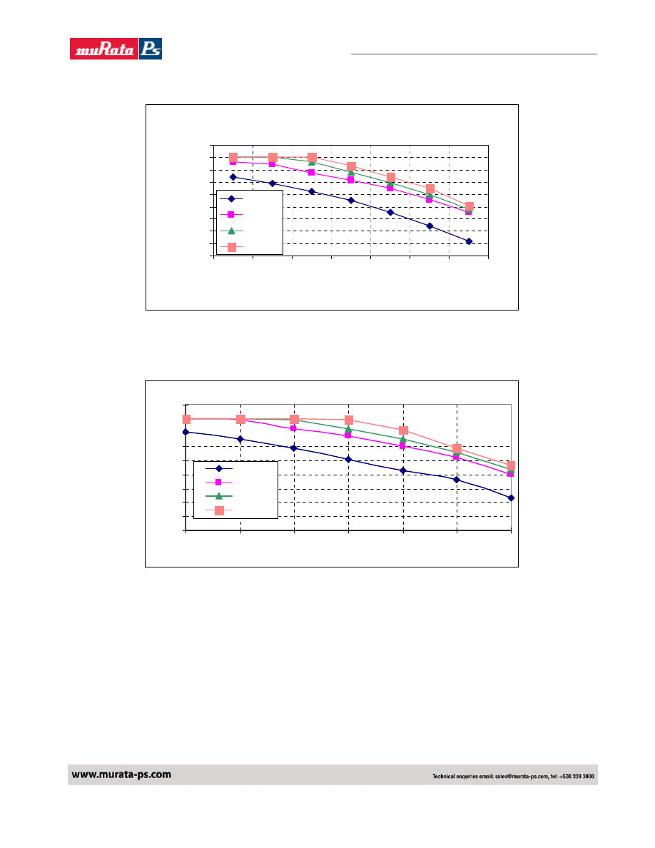
TYPICAL DERATING CURVES SIP/SMT VERSION
SMT16W-12S05A Vo=0.75V Derating Curve
0
2
4
6
8
10
12
14
16
18
30
40
50
60
70
80
90
Ambient Temperature (C)
O
u
tput
C
u
rr
e
n
t (
A
0LFM
100LFM
200LFM
300LFM
Fig. 2. SMT Power Derating vs Output Current for 12Vin 0.75V Out.
SIP16W-12S05A Derating Curve V1.0 Vout=0.75V
0
2
4
6
8
10
12
14
16
18
30
40
50
60
70
80
90
0LFM
100LFM
200LFM
300LFM
Fig. 3. SIP Power Derating vs Output Current for 12Vin 0.75V Out.
NFA016 SMT Derating Curve Vout=0.75V
NFA016 SIP Derating Curve Vout=0.75V
Output Cu
rre
nt (A)
Ambient Temperature (C)
Murata Power Solutions
5
NFA016_6200890000_B01_21/04/08
Non-Isolated 16A SIP/SMT DC/DC Converters
VOLANT NFA016 Series
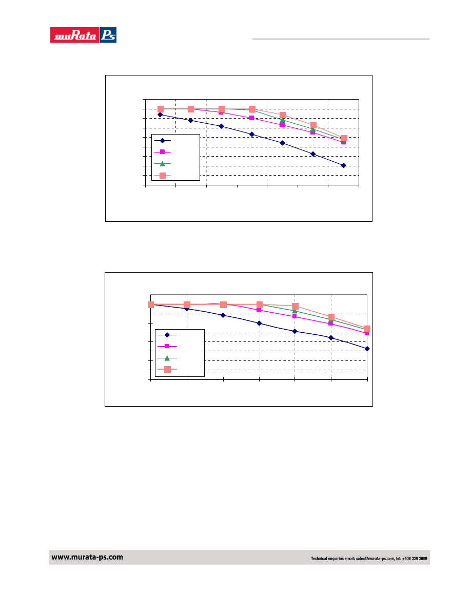
SMT16W-12S05A Vo=1.2V Derating Curve
0
2
4
6
8
10
12
14
16
18
30
40
50
60
70
80
90
Ambient Temperature (C)
O
u
tput
C
u
rr
e
n
t (
A
0LFM
100LFM
200LFM
300LFM
Fig 4. SMT Power Derating vs Output Current for 12Vin 1.2V Out.
SIP16W-12S05A Derating Curve V1.0 Vout=1.2V
0
2
4
6
8
10
12
14
16
18
30
40
50
60
70
80
90
0LFM
100LFM
200LFM
300LFM
Fig 5. SIP Power Derating vs Output Current for 12Vin 1.2V Out.
NFA016 SMT Derating Curve Vout=1.2V
NFA016 SIP Derating Curve Vout=1.2V
Out
p
ut Cu
rre
nt
(A
)
Ambient Temperature (C)
Murata Power Solutions
6
NFA016_6200890000_B01_21/04/08
Non-Isolated 16A SIP/SMT DC/DC Converters
VOLANT NFA016 Series
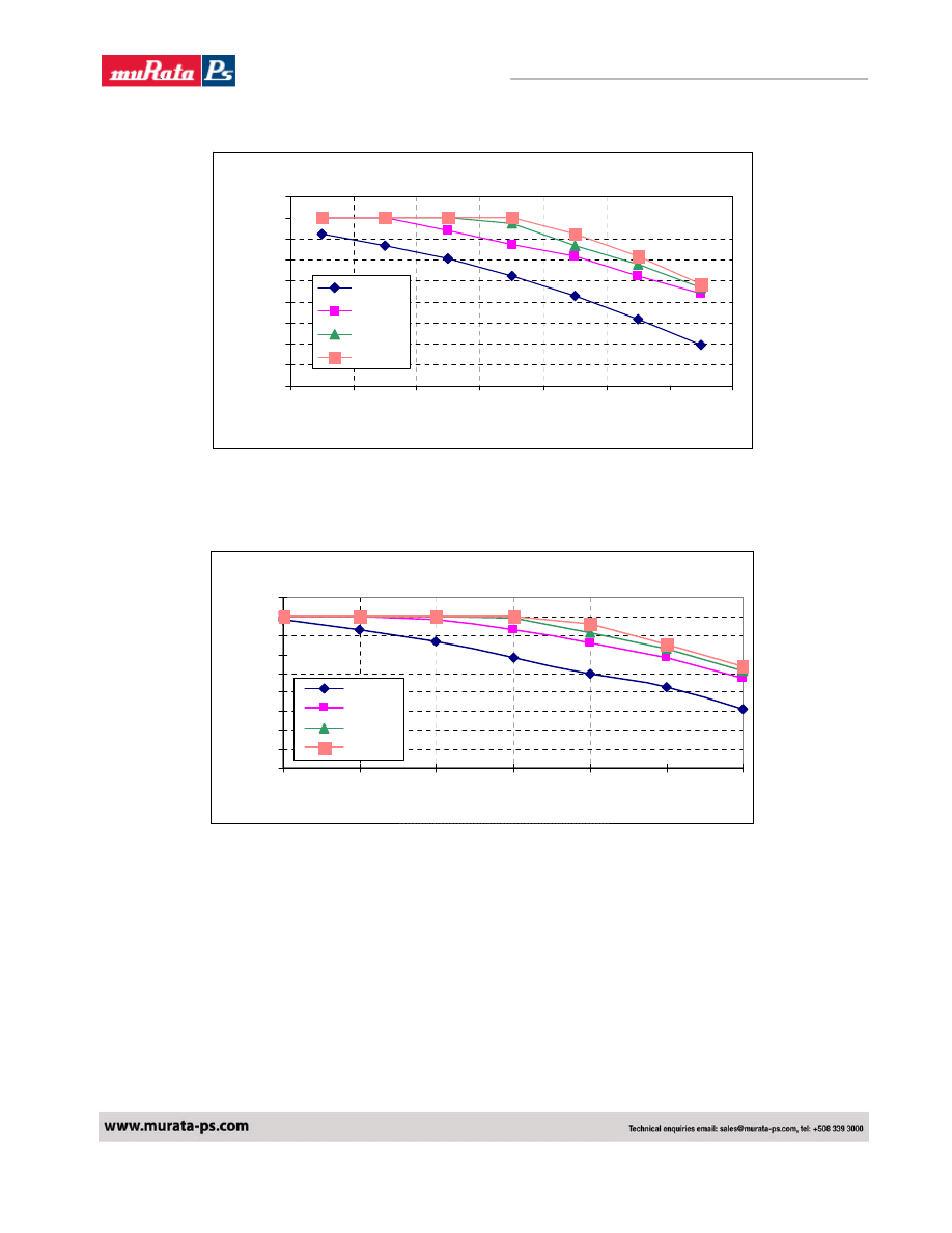
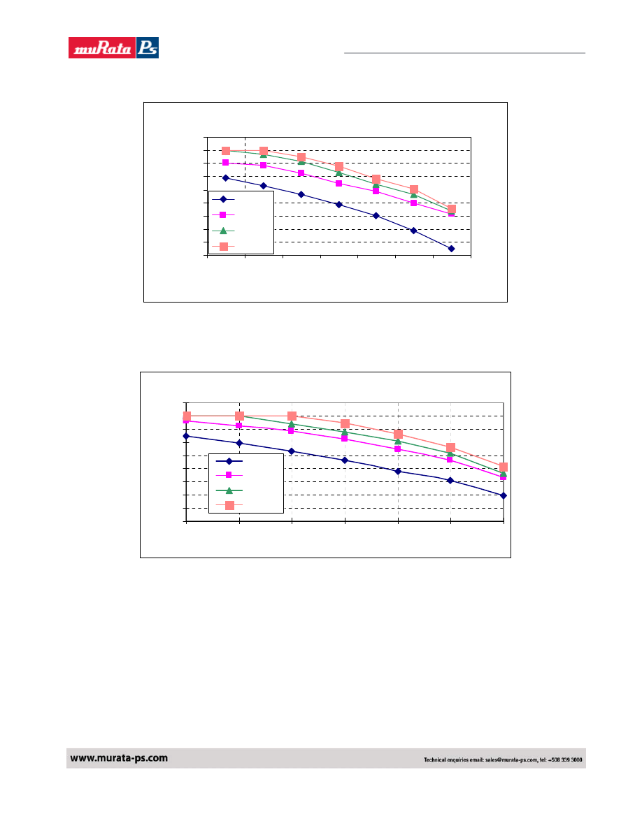
SMT16W-12S05A Vo=1.5V Derating Curve
0
2
4
6
8
10
12
14
16
18
30
40
50
60
70
80
90
Ambient Temperature (C)
O
u
tput
C
u
rr
e
n
t (
A
0LFM
100LFM
200LFM
300LFM
Fig 6. SMT Power Derating vs Output Current for 12Vin 1.5V Out.
SIP16W-12S05A Derating Curve V1.0 Vout=1.5V
0
2
4
6
8
10
12
14
16
18
30
40
50
60
70
80
90
0LFM
100LFM
200LFM
300LFM
Fig 7. SIP Power Derating vs Output Current for 12Vin 1.5V Out.
NFA016 SMT Derating Curve Vout=1.5V
NFA016 SIP Derating Curve Vout=1.5V
Out
p
ut Cu
rre
nt
(A
)
Ambient Temperature (C)
Murata Power Solutions
7
NFA016_6200890000_B01_21/04/08
Non-Isolated 16A SIP/SMT DC/DC Converters
VOLANT NFA016 Series
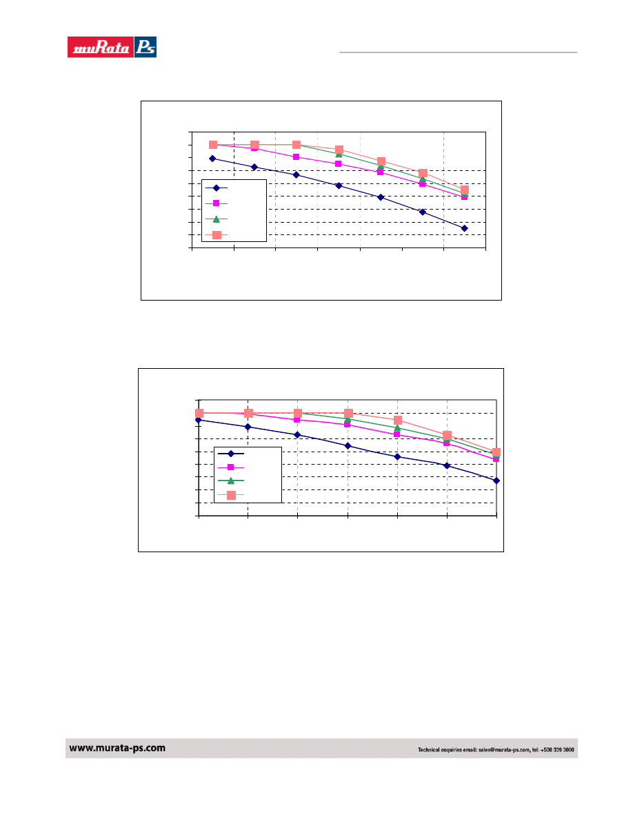
SMT16W-12S05A Vo=1.8V Derating Curve
0
2
4
6
8
10
12
14
16
18
30
40
50
60
70
80
90
Ambient Temperature (C)
O
u
tp
u
t C
u
rr
e
n
t (
A
)
0LFM
100LFM
200LFM
300LFM
Fig 8. SMT Power Derating vs Output Current for 12Vin 1.8V Out.
SIP16W-12S05A Derating Curve V1.0 Vout=1.8V
0
2
4
6
8
10
12
14
16
18
30
40
50
60
70
80
90
0LFM
100LFM
200LFM
300LFM
Fig 9. SIP Power Derating vs Output Current for 12Vin 1.8V Out.
NFA016 SMT Derating Curve Vout=1.8V
NFA016 SIP Derating Curve Vout=1.8V
Out
p
ut Cu
rre
nt
(A
)
Ambient Temperature (C)
Output Cu
rre
nt (A)

Murata Power Solutions
8
NFA016_6200890000_B01_21/04/08
Non-Isolated 16A SIP/SMT DC/DC Converters
VOLANT NFA016 Series
SMT16W-12S05A Vo=2.0V Derating Curve
0
2
4
6
8
10
12
14
16
18
30
40
50
60
70
80
90
Ambient Temperature (C)
O
u
tp
u
t C
u
rr
e
n
t (
A
)
0LFM
100LFM
200LFM
300LFM
Fig 10. SMT Power Derating vs Output Current for 12Vin 2.0V Out.
SIP16W-12S05A Derating Curve V1.0 Vout=2.0V
0
2
4
6
8
10
12
14
16
18
30
40
50
60
70
80
90
0LFM
100LFM
200LFM
300LFM
Fig 11. SIP Power Derating vs Output Current for 12Vin 2.0V Out.
NFA016 SMT Derating Curve Vout=2.0V
NFA016 SIP Derating Curve Vout=2.0V
Out
p
ut Cu
rre
nt
(A
)
Ambient Temperature (C)
Murata Power Solutions
9
NFA016_6200890000_B01_21/04/08
Non-Isolated 16A SIP/SMT DC/DC Converters
VOLANT NFA016 Series
SMT16W-12S05A Vo=2.5V Derating Curve
0
2
4
6
8
10
12
14
16
18
30
40
50
60
70
80
90
Ambient Temperature (C)
O
u
tp
u
t Cu
rr
e
n
t
(A
0LFM
100LFM
200LFM
300LFM
Fig 12. SMT Power Derating vs Output Current for 12Vin 2.5V Out.
SIP16W-12S05A derating curve V1.0 Vout=2.5V
0
2
4
6
8
10
12
14
16
18
30
40
50
60
70
80
90
Ambient Temperature(
o
C)
0LFM
100LFM
200LFM
300LFM
Fig 13. SIP Power Derating vs Output Current for 12Vin 2.5V Out.
NFA016 SMT Derating Curve Vout=2.5V
NFA016 SIP Derating Curve Vout=2.5V
Out
p
ut Cu
rre
nt
(A
)
Murata Power Solutions
10
NFA016_6200890000_B01_21/04/08
Non-Isolated 16A SIP/SMT DC/DC Converters
VOLANT NFA016 Series
SMT16W-12S05A Vo=3.3V Derating Curve
0
2
4
6
8
10
12
14
16
18
30
40
50
60
70
80
90
Ambient Temperature (C)
O
u
tput
C
u
rr
e
n
t (
A
0LFM
100LFM
200LFM
300LFM
Fig. 14. SMT Power Derating vs Output Current for 12Vin 3.3V Out.
SIP16W-12S05A Derating Curve V1.2 Vout=3.3V
0
2
4
6
8
10
12
14
16
18
30
40
50
60
70
80
90
Ambient Temperature(
o
C)
0LFM
100LFM
200LFM
300LFM
Fig 15. SIP Power Derating vs Output Current for 12Vin 3.3V Out.
NFA016 SMT Derating Curve Vout=3.3V
NFA016 SIP Derating Curve Vout=3.3V
Output
Cu
rre
nt
(A)
Murata Power Solutions
11
NFA016_6200890000_B01_21/04/08
Non-Isolated 16A SIP/SMT DC/DC Converters
VOLANT NFA016 Series
SMT16W-12S05A Vo=5.0V Derating Curve
0
2
4
6
8
10
12
14
16
18
30
40
50
60
70
80
90
Ambient Temperature (C)
O
u
tput
C
u
rr
e
n
t (
A
0LFM
100LFM
200LFM
300LFM
Fig. 16. SMT Power Derating vs Output Current for 12Vin 5.0V Out
SIP16W-12S05A Derating Curve V1.0 Vout=5.0V
0
2
4
6
8
10
12
14
16
18
30
40
50
60
70
80
90
Ambient Temperature(
o
C)
0LFM
100LFM
200LFM
300LFM
Fig 17. SIP Power Derating vs Output Current for 12Vin 5.0V Out.
NFA016 SMT Derating Curve Vout=5.0V
NFA016 SIP Derating Curve Vout=5.0V
Output
Cu
rre
nt
(A)
Murata Power Solutions
12
NFA016_6200890000_B01_21/04/08
Non-Isolated 16A SIP/SMT DC/DC Converters
VOLANT NFA016 Series
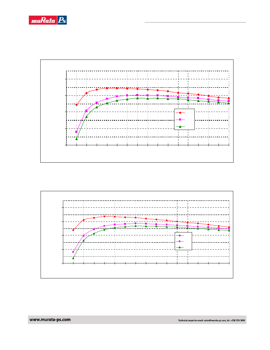
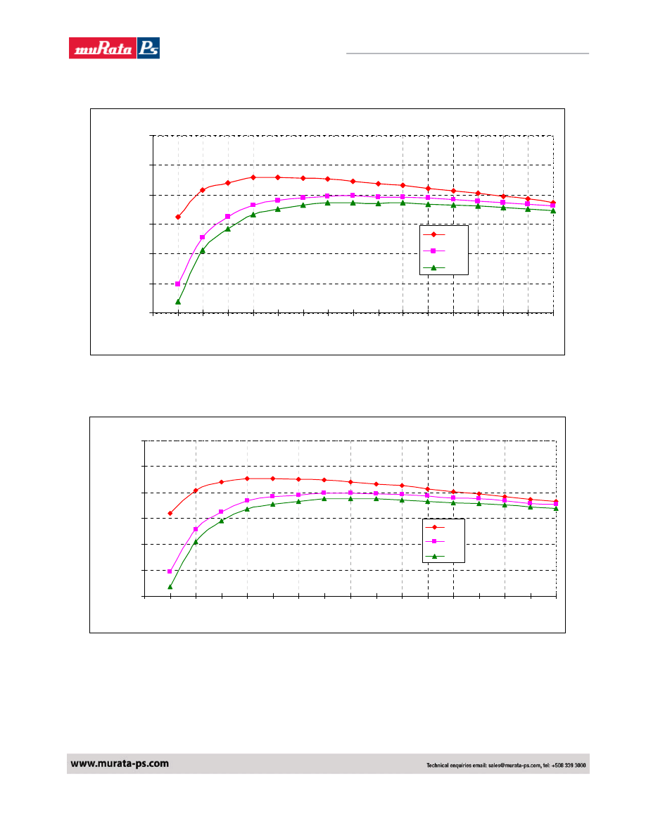
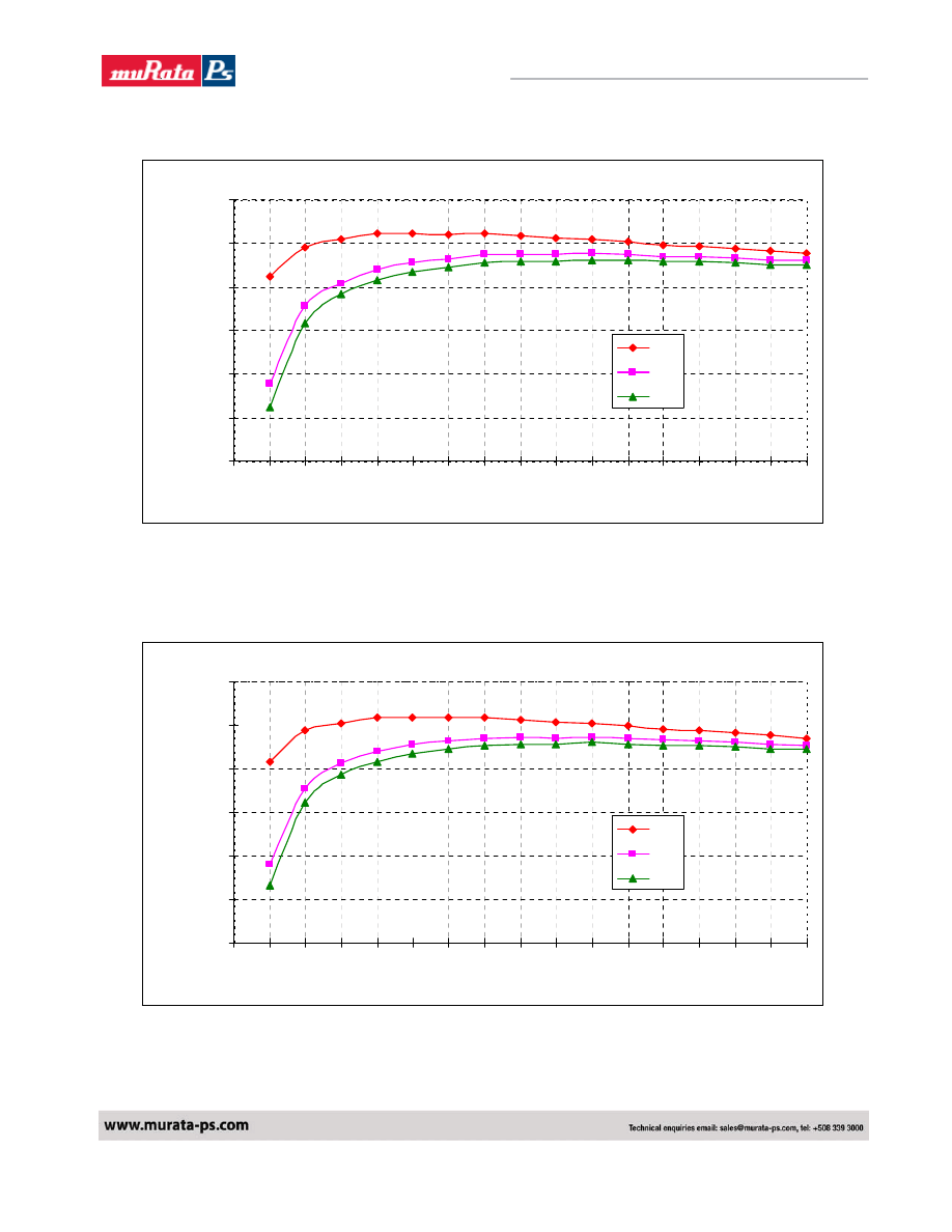
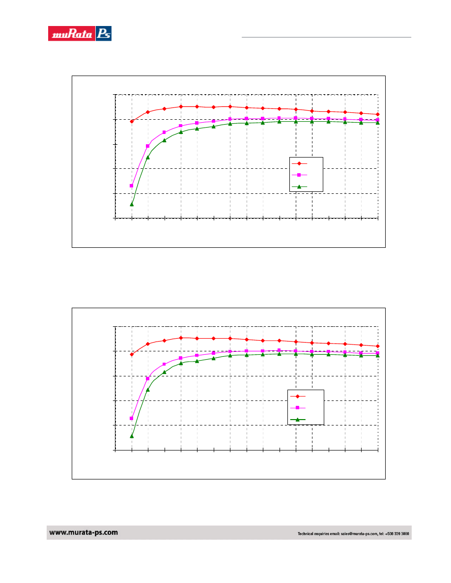
TYPICAL EFFICIENCY CURVES FOR VARIOUS VOLTAGE MODELS SIP/SMT VERSION.
SMT16W-12S05A Vo: 0.75V (Eff Vs Io)
55%
65%
75%
85%
95%
0
1
2
3
4
5
6
7
8
9
10
11
12
13
14
15
16
Current Load (A)
E
ffi
c
ie
n
c
y
(
%
6V
12V
14V
Fig 18. SMT Efficiency Curves for Vout=075V (25C)
SIP16W-12S05A Vo: 0.75V (Eff Vs Io)
55%
65%
75%
85%
95%
0
1
2
3
4
5
6
7
8
9
10
11
12
13
14
15
16
Current Load (A)
E
ff
ici
ency (
%
6V
12V
14V
Fig 19. SIP Efficiency Curves for Vout=0.75V (25C)
NFA016 SMT Efficiency Curve Vout=0.75V
NFA016 SIP Efficiency Curve Vout=0.75V
Murata Power Solutions
13
NFA016_6200890000_B01_21/04/08
Non-Isolated 16A SIP/SMT DC/DC Converters
VOLANT NFA016 Series
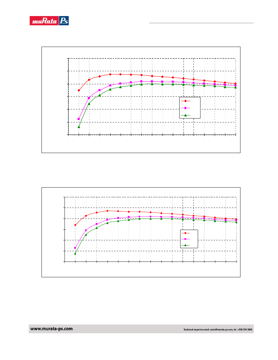
SMT16W-12S05A Vo: 1.2V (Eff Vs Io)
60%
70%
80%
90%
100%
0
1
2
3
4
5
6
7
8
9
10
11
12
13
14
15
16
Current Load (A)
E
ff
ici
ency (
%
6V
12V
14V
Fig 20. SMT Efficiency Curves for Vout=1.2V (25C)
SIP16W-12S05A Vo: 1.2V (Eff Vs Io)
60%
70%
80%
90%
100%
0
1
2
3
4
5
6
7
8
9
10
11
12
13
14
15
16
Current Load (A)
E
ffi
c
ie
n
c
y
(
%
6V
12V
14V
Fig 21. SIP Efficiency Curves for Vout=1.2V (25C)
NFA016 SMT Efficiency Curve Vout=1.2V
NFA016 SIP Efficiency Curve Vout=1.2V
Murata Power Solutions
14
NFA016_6200890000_B01_21/04/08
Non-Isolated 16A SIP/SMT DC/DC Converters
VOLANT NFA016 Series
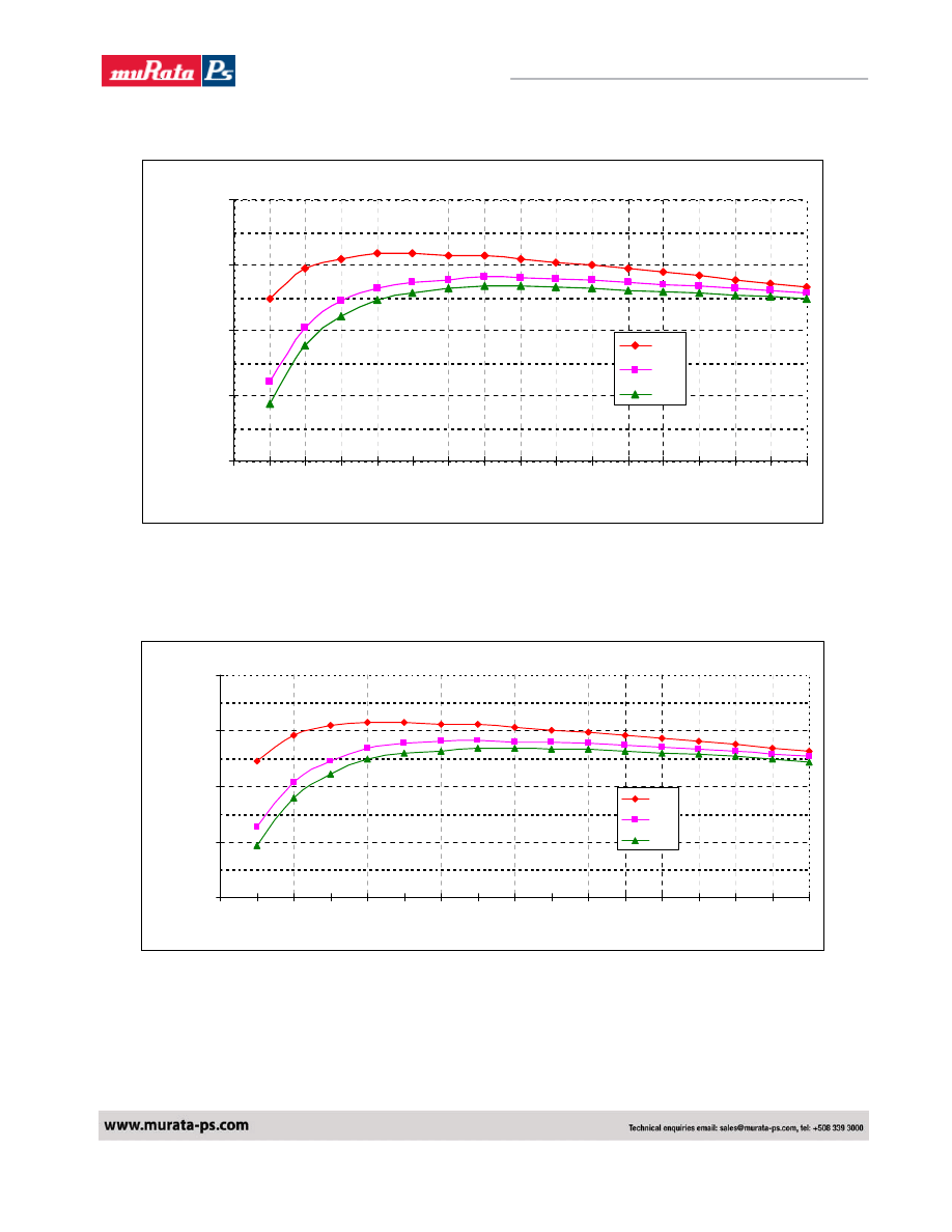
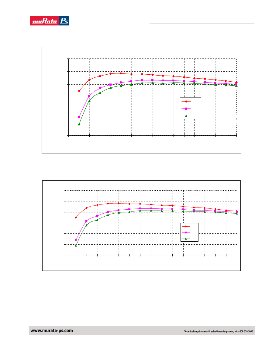
SMT16W-12S05A Vo: 1.5V (Eff Vs Io)
70%
75%
80%
85%
90%
95%
100%
0
1
2
3
4
5
6
7
8
9
10
11
12
13
14
15
16
Current Load (A)
E
ff
ici
ency (
%
6V
12V
14V
Fig 22. SMT Efficiency Curves for Vout=1.5V (25C)
SIP16W-12S05A Vo: 1.5V (Eff Vs Io)
70%
75%
80%
85%
90%
95%
100%
0
1
2
3
4
5
6
7
8
9
10
11
12
13
14
15
16
Current Load (A)
E
ffi
c
ie
n
c
y
(
%
6V
12V
14V
Fig 23. SIP Efficiency Curves for Vout=1.5V (25C)
NFA016 SMT Efficiency Curve Vout=1.5V
NFA016 SIP Efficiency Curve Vout=1.5V
Murata Power Solutions
15
NFA016_6200890000_B01_21/04/08
Non-Isolated 16A SIP/SMT DC/DC Converters
VOLANT NFA016 Series
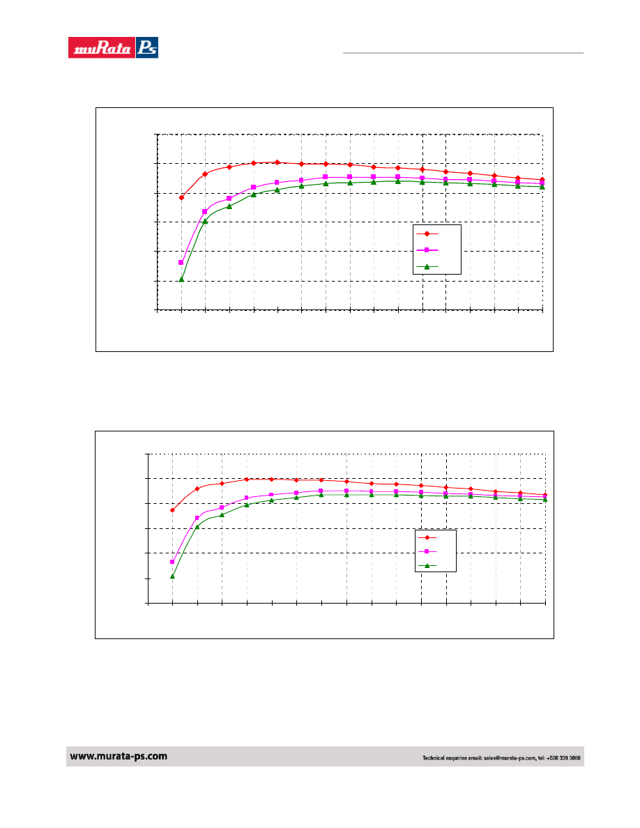
SMT16W-12S05A Vo: 1.8V (Eff Vs Io)
70%
75%
80%
85%
90%
95%
100%
0
1
2
3
4
5
6
7
8
9
10
11
12
13
14
15
16
Current Load (A)
E
ff
ici
ency (
%
6V
12V
14V
Fig 24. SMT Efficiency Curves for Vout=1.8V (25C)
SIP16W-12S05A Vo: 1.8V (Eff Vs Io)
70%
75%
80%
85%
90%
95%
100%
0
1
2
3
4
5
6
7
8
9
10
11
12
13
14
15
16
Current Load (A)
Ef
fi
ci
ency (
%
6V
12V
14V
Fig 25. SIP Efficiency Curves for Vout=1.8V (25C)
NFA016 SMT Efficiency Curve Vout=1.8V
NFA016 SIP Efficiency Curve Vout=1.8V
Murata Power Solutions
16
NFA016_6200890000_B01_21/04/08
Non-Isolated 16A SIP/SMT DC/DC Converters
VOLANT NFA016 Series
SMT16W-12S05A Vo:2.0V (Eff Vs Io)
70%
75%
80%
85%
90%
95%
100%
0
1
2
3
4
5
6
7
8
9
10
11
12
13
14
15
16
Current Load (A)
E
ff
ici
ency (
%
6V
12V
14V
Fig 26. SMT Efficiency Curves for Vout=2.0V (25C)
SIP16W-12S05A Vo: 2.0V (Eff Vs Io)
70%
75%
80%
85%
90%
95%
100%
0
1
2
3
4
5
6
7
8
9
10
11
12
13
14
15
16
Current Load (A)
E
ffi
c
ie
n
c
y
(
%
6V
12V
14V
Fig 27. SIP Efficiency Curves for Vout=2.0V (25C)
NFA016 SMT Efficiency Curve Vout=2.0V
NFA016 SIP Efficiency Curve Vout=2.0V
Murata Power Solutions
17
NFA016_6200890000_B01_21/04/08
Non-Isolated 16A SIP/SMT DC/DC Converters
VOLANT NFA016 Series
SMT16W-12S05A Vo: 2.5V (Eff Vs Io)
70%
75%
80%
85%
90%
95%
100%
0
1
2
3
4
5
6
7
8
9
10
11
12
13
14
15
16
Current Load (A)
E
ff
ici
ency (
%
6V
12V
14V
Fig 28. SMT Efficiency Curves for Vout=2.5V (25C)
SIP16W-12S05A Vo: 2.5V (Eff Vs Io)
70%
75%
80%
85%
90%
95%
100%
0
1
2
3
4
5
6
7
8
9
10
11
12
13
14
15
16
Current Load (A)
E
ffi
c
ie
n
c
y
(
%
6V
12V
14V
Fig 29. SIP Efficiency Curves for Vout=2.5V (25C)
NFA016 SMT Efficiency Curve Vout=2.5V
NFA016 SIP Efficiency Curve Vout=2.5V
Murata Power Solutions
18
NFA016_6200890000_B01_21/04/08
Non-Isolated 16A SIP/SMT DC/DC Converters
VOLANT NFA016 Series
SMT16W-12S05A Vo:3.3V (Eff Vs Io)
70%
75%
80%
85%
90%
95%
100%
0
1
2
3
4
5
6
7
8
9
10
11
12
13
14
15
16
Current Load (A)
E
ff
ici
ency (
%
6V
12V
14V
Fig 30. SMT Efficiency Curves for Vout=3.3V (25C)
SIP16W-12S05A Vo:3.3V (Eff Vs Io)
70%
75%
80%
85%
90%
95%
100%
0
1
2
3
4
5
6
7
8
9
10
11
12
13
14
15
16
Current Load (A)
E
ff
ici
ency (
%
6V
12V
14V
Fig 31. SIP Efficiency Curves for Vout=3.3V (25C)
NFA016 SMT Efficiency Curve Vout=3.3V
NFA016 SIP Efficiency Curve Vout=3.3V
Murata Power Solutions
19
NFA016_6200890000_B01_21/04/08
Non-Isolated 16A SIP/SMT DC/DC Converters
VOLANT NFA016 Series
SMT16W-12S05A Vo: 5.0V (Eff Vs Io)
75%
80%
85%
90%
95%
100%
0
1
2
3
4
5
6
7
8
9
10
11
12
13
14
15
16
Current Load (A)
E
ff
ici
ency (
%
6V
12V
14V
Fig 32. SMT Efficiency Curves for Vout=5.0V (25C)
SIP16W-12S05A Vo: 5.0V (Eff Vs Io)
75%
80%
85%
90%
95%
100%
0
1
2
3
4
5
6
7
8
9
10
11
12
13
14
15
16
Current Load (A)
E
ff
ici
ency (
%
6.5V
12V
14V
Fig 33. SIP Efficiency Curves for Vout=5.0V (25C)
NFA016 SMT Efficiency Curve Vout=5.0V
NFA016 SIP Efficiency Curve Vout=5.0V
Murata Power Solutions
20
NFA016_6200890000_B01_21/04/08
Non-Isolated 16A SIP/SMT DC/DC Converters
VOLANT NFA016 Series
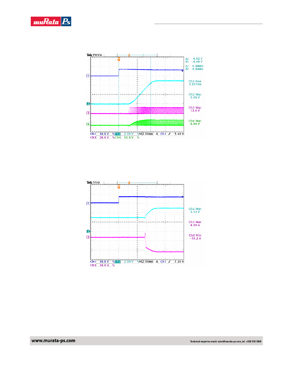
Typical Start Up
Ch1. Vin
Ch2. Vout, Full load.
Ch3. Q1-Vgs
Ch4. Q2-Vgs
Typical Start Up with pre-bias
Ch1 : Enable
Ch2 : Vout
Ch3 : Output current at Full Load.
Murata Power Solutions
21
NFA016_6200890000_B01_21/04/08
Non-Isolated 16A SIP/SMT DC/DC Converters
VOLANT NFA016 Series
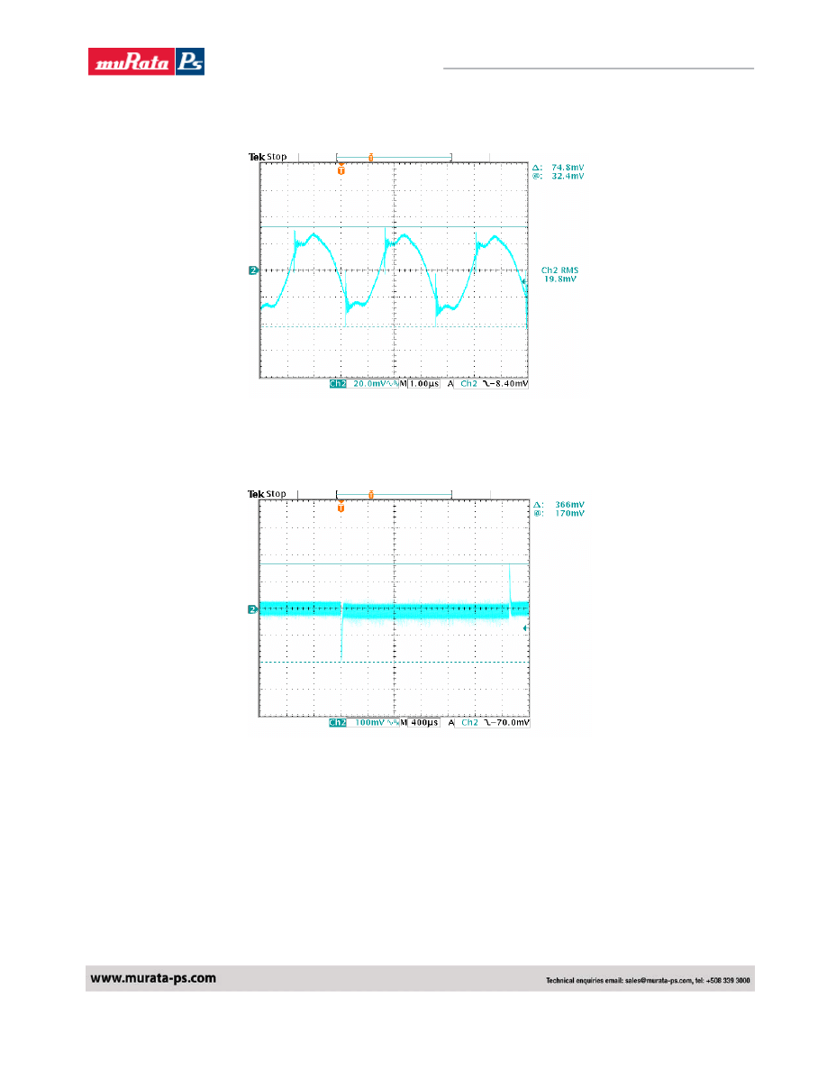
Typical Output Noise and Ripple
Vin = 12Vdc , Vo=5.0V/16A
Output with 1uF ceramic and 10uF tantalum capacitor
Typical Output Transient Response
Vin = 12Vdc , Vo=5.0V , 50% - 100% - 50% Load change , @2.5A/uS
Murata Power Solutions
22
NFA016_6200890000_B01_21/04/08
Non-Isolated 16A SIP/SMT DC/DC Converters
VOLANT NFA016 Series
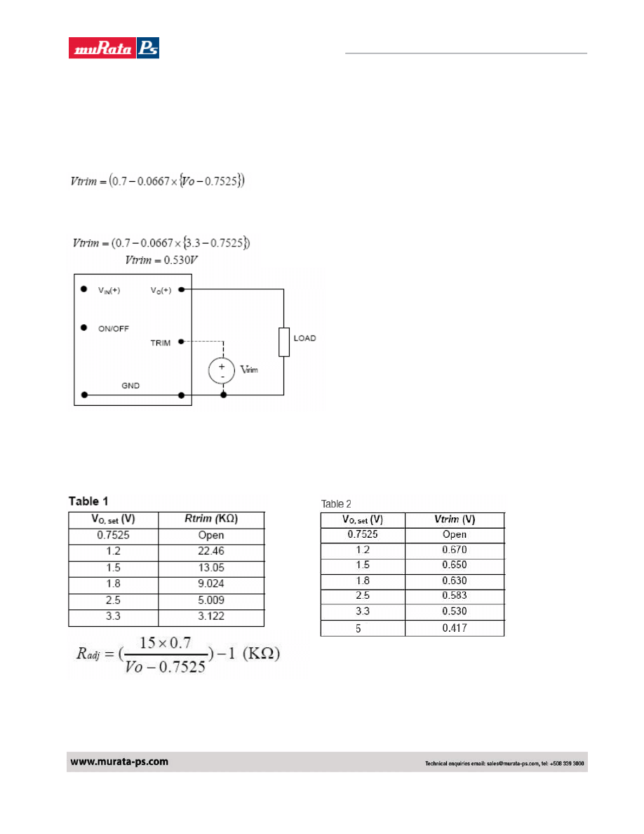
Output Voltage Set point adjustment.
NFA Series can also be programmed by applying a voltage between the TRIM and GND pins (Figure
below). The following equation can be used to determine the value of Vtrim needed to obtain a desired
output voltage Vo:
For example, to program the output voltage of NFA Series module to 3.3 Vdc, Vtrim is calculated as
follows:
Circuit Configuration for programming Output voltage using external voltage source
Table 1 provides Rtrim values for some common output voltages, whileTable 2 provides values of the
external voltage source, Vtrim for the same common output voltages.
By using a 1% tolerance trim resistor, set point tolerance of ±2% is achieved as specified in the
electrical specification.
Murata Power Solutions
23
NFA016_6200890000_B01_21/04/08
Non-Isolated 16A SIP/SMT DC/DC Converters
VOLANT NFA016 Series
Remote Sense:
All Celestica SMT/SIP power modules offer an option for remote sense. The remote sense compensates for any
distribution drops to accurately control voltage at the point of load. The voltage between the sense
pin to Vout
pin should not exceed 0.5V.
Voltage Sequencing:
NFA series power modules offer the ability to precisely sequence output voltage rise. The sequence feature
limits the output voltage to that presented at the Sequence pin. For example, if the sequence pin is connected
to a variable voltage source, and the converter is enabled, output voltage will track the voltage applied to the
sequence pin, to a maximum of the programmed output voltage. If this feature is not required, the sequence pin
should remain unconnected. In practice, the Sequence pin of a lower voltage converter may be connected to a
higher voltage source to ensure the lower voltage does not exceed the higher voltage during power on and
power off. If multiple NFA series converters are used, all Sequence pins may be connected to the same higher
voltage. In this way, all voltage rails will rise at the same rate, and cease to rise at their respective programmed
output voltages.
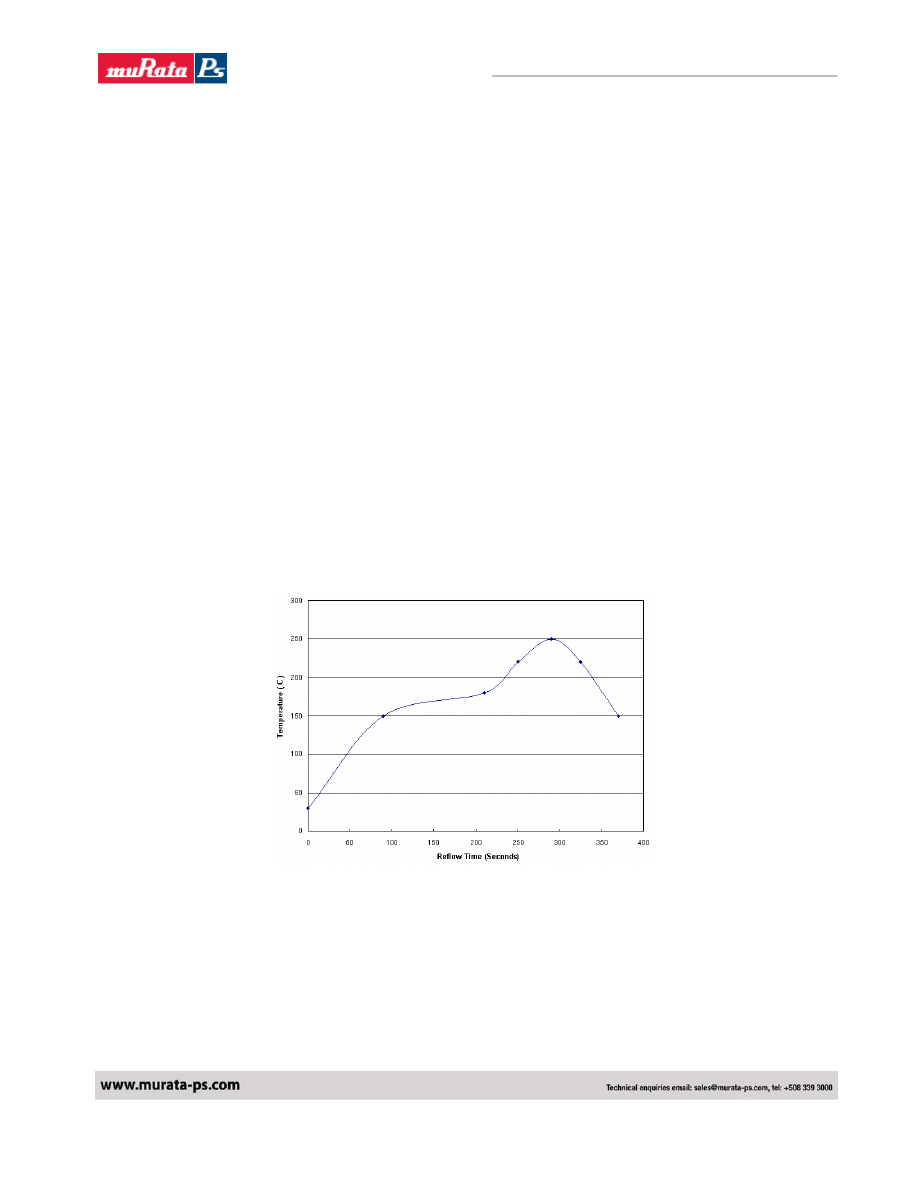
SMT Lead free Reflow profile
1. Ramp up rate during preheat : 1.33
℃/Sec ( From 30℃ to 150℃ )
2. Soaking temperature : 0.29
℃/Sec ( From 150℃ to 180℃ )
3. Ramp up rate during reflow : 0.8
℃/Sec ( From 220℃ to 250℃ )
4. Peak temperature : 250
℃, above 220℃ 40 to 70 Seconds
5.
Ramp up rate during cooling : -1.56
℃/Sec ( From 220℃ to 150℃ )
Murata Power Solutions
24
NFA016_6200890000_B01_21/04/08
Non-Isolated 16A SIP/SMT DC/DC Converters
VOLANT NFA016 Series
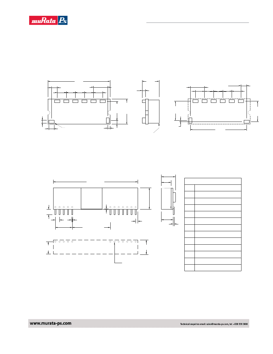
Mechanical and pinning Information.
Given below is the outline drawing showing physical dimensions of the SIP & SMT package.
The external dimensions for SMT package are 33.00mm X 13.46mm X 9.3mm.
10.29
13.46
1.22
7.54
4.83
4.83
4.83
3.05
33.0
1.91
1.60
2.84
(1.30)
(0.120)
(0.190) (0.190) (0.190)
(0.297)
(0.405) (0.530)
(0.075)
(0.048)
(0.112)
(0.063)
+SENSE
TRIM
+VO
COM
ON/OFF
+VIN
1.65
8.80
(0.346)
(0.065)
max.
+SENSE TRIM
+VO
COM
ON/OFF
+VIN
7.54
4.83
4.83
4.83
3.05
10.92
0.64
10.29
(0.297)
(0.190) (0.190) (0.190)
(0.120)
(0.405)
(0.025)
(1.177)
(0.430)
29.90
PAD SIZE
MIN:3.556x2.413(0.140x0.095)
MAX:4.19x2.79(0.165x0.110)
Dimensions are in millimeters(Inches)
Tolerances :X.X = ±0.5mm(0.02in), X.XX = ±0.25mm(0.010in),unless otherwise noted.
BOTTOM VIEW OF BOARD
SURFACE MOUNT CONTACT
Dimensions are in millimetes and(inches)
L1 INDUCTOR
Recommended Pad Layout
Top View of Board
SEQ
PGood
4.83
(0.190)
4.83
(0.190)
SEQ
PGood
4.83
(0.190)
4.83
(0.190)
Whereas, the external dimensions of the SIP version are 50.8mm X 12.95mm X 8.30mm.
PIN CONNECTION
FUNCTION
+Output
+Output
+Sense
+Output
Common
PGood
Pin
1
2
3
4
5
6
All Dimmension In Inches(mm)
Tolerance :
.XX= ± 0.02 ( .X= ± 0.5 )
.XXX= ± 0.010 ( .XX= ± 0.25 )
7
8
9
10
11
Common
+V Input
+V Input
Sequence
Trim
LAYOUT PATTERN
TOP VIEW
0.33(8.4)
0.29(7.4)
1.1mm PLATED THROUGH HOLE
1.6mm PAD SIZE
0.025(0.64)
0.900(22.90)
2.00(50.8)
5
4
3
2
1
0.14(3.6)
0.100(2.54)
0.400(10.20)
SIZE SIP
0.510(12.95)
12
11
10
9
8
7
0.050(1.30)
0.010(0.25)
min.
0.28(7.1)
0.025(0.64)
0.23(5.8)
0.327(8.30)max.
6
12
On/Off Control
Murata Power Solutions
25
NFA016_6200890000_B01_21/04/08
Non-Isolated 16A SIP/SMT DC/DC Converters
VOLANT NFA016 Series
Safety Considerations
Ordering Information
Part Number
Vin*
Vout
Iout Enable Logic
Pin Length
NFA0161500B0C 6.0V - 14.0V 0.75V – 5.0V 16A
Negative
0.139"
NFA0161500S0C 6.0V - 14.0V 0.75V – 5.0V 16A
Negative
SMT
NFA0161501B0C 6.0V - 14.0V 0.75V – 5.0V 16A
Positive
0.139"
NFA0161501S0C 6.0V - 14.0V 0.75V – 5.0V 16A
Positive
SMT
* An input voltage of 6.5 Volts is required for 5 Volt output at full load.
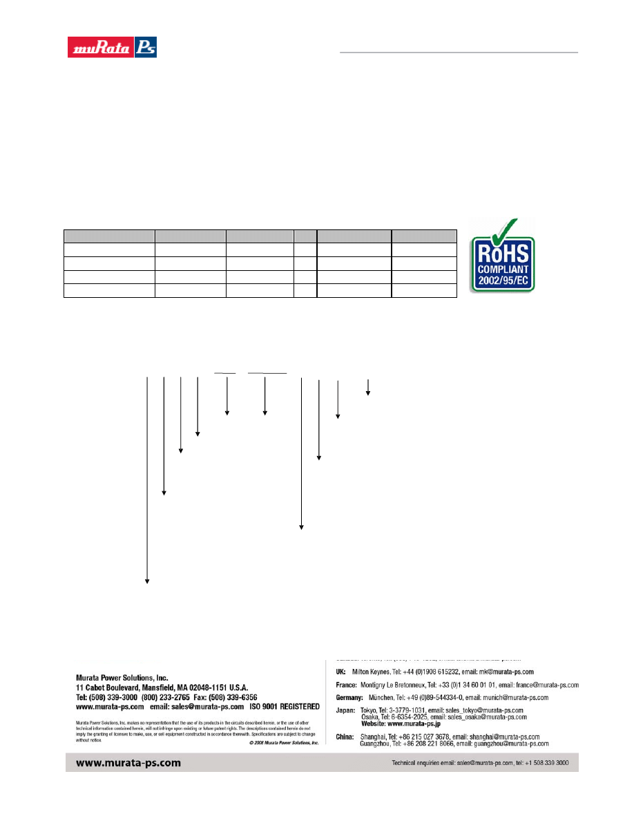
Label Information
Pin Length Option
B=0.139”
S=SMT
Enable Logic, 0 for
–ve, 1 for +ve
Vout
Iout
Place Holder
Vout Range
F=Fixed
A=Adjustable
Vin (value or range)
C= 3.3V -5.0V
E= 8.3V -14V
F= 6.0V -14V
Non-Isolated Family
0 = Standard. (No PGood option)
P = Power Good Option
C = RoHS Compliant
N F A 0 1 6 1 5 0 0 B 0 –
X
C
X = Factory control character
(not required when ordering)
The NFA series of converters are certified to IEC/EN/CSA/UL 60950. If this product is built into information technology
equipment, the installation must comply with the above standard. An external input fuse (no more 20 A recommended)
must be used to meet the above requirements. The output of the converter [Vo(+)/Vo(-)] is considered to remain within
SELV limits when the input to the converter meets SELV or TNV-2 requirements.
The converters and materials meet UL 94V-0 flammability ratings.
RoHS Compliant
The NFA016 series of converters is in compliance with the European Union Directive 2002/95/EC (RoHS) with repsect to the following sustances:
lead (Pb), mercury (Hg), cadmium (Cd), hexavalent chromium, polybrominated biphenyls (PBB) or polybrominated diphenyl ethers (PBDE).
Wyszukiwarka
Podobne podstrony:
Aiwa CDC R136 (2)
cdc qus20 120
CDC PL
cdc nca005
CDC
AVR CDC 2008 01 27, cdctiny45
cdc nea nef010 smt
cdc qus40 096
cdc eus34 096
AIWA CDC X 116 136 1360 1400
543305 CDC 20 1 A P
AIWA CDC R 146M
CDC 2313 2008 01 27, circuit
cdc eus15 120
Aiwa CDC X116 CDC X136 CDC X1360 CDC X1400 (2)
cdc nca015
How to build a USB device with PIC 18F4550 or 18F2550 (and the microchip CDC firmware)
cdc mega
więcej podobnych podstron