
CAUTION
In order to ensure your rights and interests, please read this manual carefully before you install
and use the DVR.
Use the appropriate adapter for the DVR.
To protect the main chip from thunder striking, please make sur e the gro und wire is correc tly
connected before using the DVR.
Do not expose the DVR to rain or use it under high humidity circumstance.
This DVR cannot be installed at the places with much dust, and avoid potential m echa nica l
vibration or impact.
Install this DVR under good air circulation conditions. Do not place it near the heater or under
direct sunlight.
Please choose high quality hard disk (HDD), which could meet the working demand of the DVR.
For its quality, please purchase hard disk from regular merchants, and do no t use the Western
Digital hard disk.
Network Digital Video Recorder Operation Manual ( V1.0 )

CAUTION
Before connecting to other facilities, please disconnect the power supply and pull the power
line plug out from the power socket.
In case of any solid or liquid coming into the case, please disconne ct the p ower sup ply imme -
diately,and the DVR can be restarted only after being checked by qualified servicemen.
If the DVR is not in use for a long period of time, please disconnect the power supply and pull
the power line plug out from the power socket.
This is a precise instrument. No internal part can be repaired by the users. I f fault occurs, it is
necessary to ask qualified servicemen to repair it or contact the dealer.
Network Digital Video Recorder Operation Manual ( V1.0 )

6
6
6
8
8
11
14
19
20
Table of contents
Chapter II Operation instructions
Chapter I Product Introduction
1.1 Summary
1.2 Functions and features
2.1 Description of front panel
2.2 Description of rear panel
2.3 Description of alarm and audio port in the rear panel
2.4 Remote control operation
2.5 Mouse operation
Chapter III Menu Setup
3.1 Summary of menu operation
3.2 System setup
Network Digital Video Recorder Operation Manual ( V1.0 )
3
15
18
19

3.3 Camera setup
3.4 Record setup
3.5 Schedule setup
3.6 Motion alarm
3.7 PTZ setup
3.8 Network setup
3.9 Alarm setup
3.10 Disk management
3.11 User setup
23
22
25
26
27
28
29
30
31
31
31
24
34
35
37
Chapter IV Basic Operations
4.1 Turn on DVR
4.2 Live screen
4.3 Software update
4.4 PTZ control
4.5 System information
Network Digital Video Recorder Operation Manual ( V1.0 )
4

38
39
39
42
42
43
43
44
45
43
Appendix 1 Technical parameters
Appendix 2 Trouble shooting
4.6 Recording preparation
4.7 Recording operation
4.8 Search, playback and backup
4.9 Audio setup
4.10 SEQ
4.11 User login
4.12 PC Client software instruction
4.13 Power off
Network Digital Video Recorder Operation Manual ( V1.0 )
5

1.1
Summary
Chapter I Product Introduction
This equipment is a standalone digital hard disk video recorder specially designed for security .It adopts the emb-
edded processor and embedded operating system and integrates with latest technologies in IT field, such as video fre-
quency/audio frequency compression/decompression, large capacity hard disk storage, TCP/IP net work remote cont-
rol etc., investing the system with high intellectualization and stability.
This equipment supports various networks including Ethernet and Internet to realize remote audi o/video synchr-
onization. With easy operation, it can be applied to the security for banks, telecom, schools, hospitals, supermarkets,
residential quarters, factories, companies, warehouses, restaurants, hotels, parks, museums, water conservancy facili-
ties, entertainment places and other fields.
1.2
Functions and features
Support PAL & NTSC video signal input.
Support OSD languages of multiple countries.
Support external alarm, motion detection and exact time recording.
Support audio recording, playing and live mode listening.
Video recording, play back, network simultaneously.
Network Digital Video Recorder Operation Manual ( V1.0 )
6

If the electricity suddenly goes off while recording, it will continues to record automatically as soon as the electr-
icity resumes.
Flexible display mode: full screen, quad, and 4 channels arbitrarily.
Support CMS
Support DDNS
Support network preview, playback, setup, remote video recording, PTZ control and camera setup.
Support IE browsing function and network remote client.
Support Internet backup ,USB backup.
Support mouse operation with high sensitivity
Support DVD-RW and 1000G hard disk
Support VGA output
Support remote control
Convenient & precise video searching
Control PTZ through RS485
Specially designed dedicated file system for video to increase more than 10 times of service life of hard disk
Fully independent from PC platform and free from computer breakdown due to improper operations, complicated
management & operations as well as virus infection, and is of high stability.
Operating system: Linux
Compressed chip: ASIC
Network Digital Video Recorder Operation Manual ( V1.0 )
7
Chapter II Operation Instructions
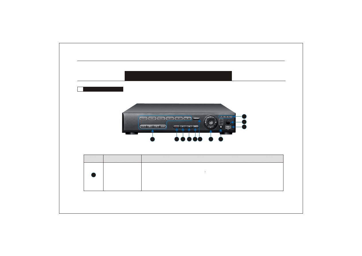
2.1
Description of front panel
1
2
3
4
5 6
7
8
9
10
11
a) input numbers.
b) keystroke 19 : select channels
c) [0/10+]: input the number "0".
d) input password
1
Description
Name
No.
Number keys
Network Digital Video Recorder Operation Manual ( V1.0 )
8
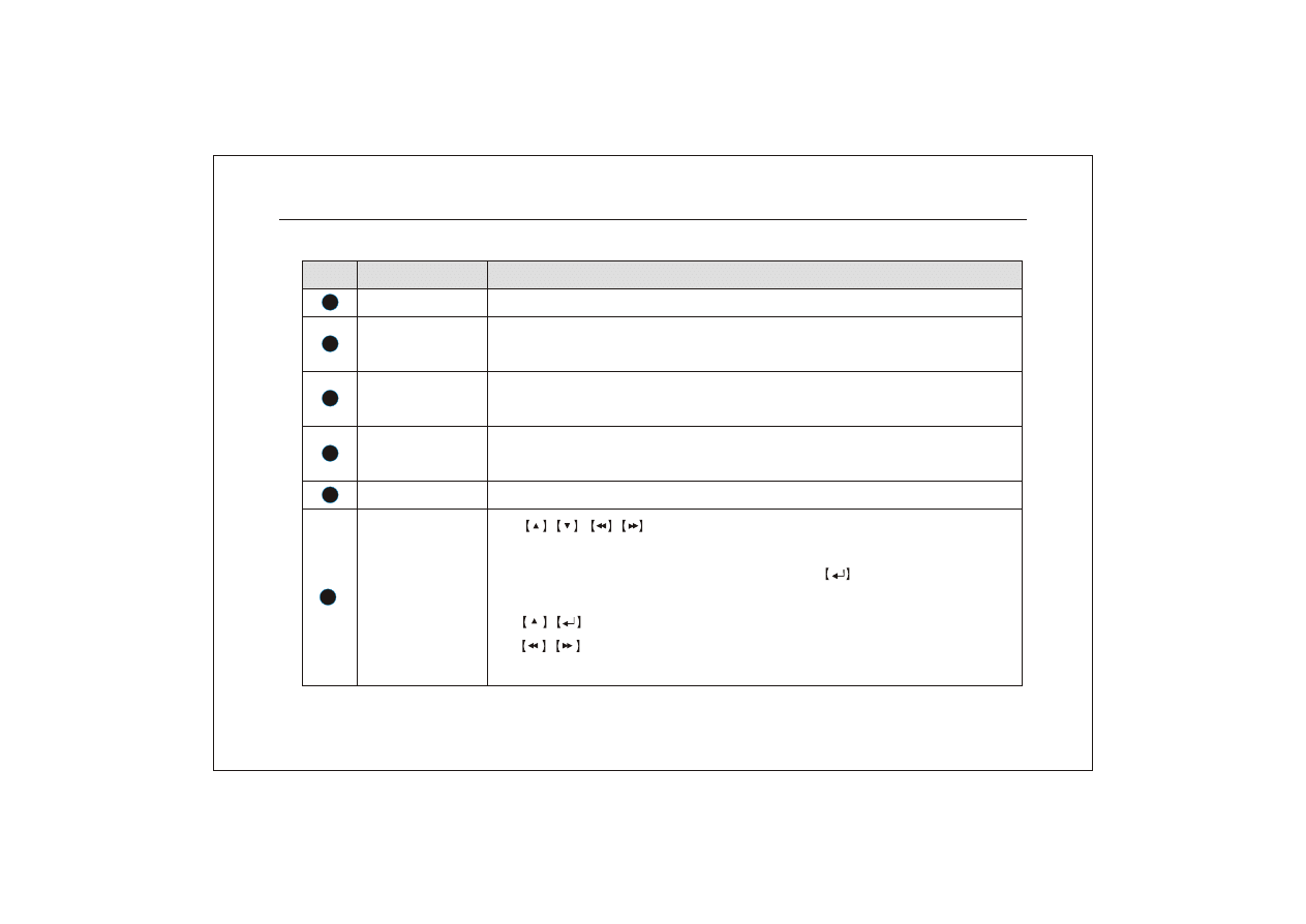
2
3
4
5
6
7
a)
are direction keys. In menu mode, select th e listed options
upward/downward/leftward/rightward; in PTZ control mode, control the dome
to rotate upward/downward/leftward/rightward.
confirm the selection and
operation.
b)
could be Quad and nine-split-screen key in live mode.
c)
rewind and forward in playback mode. Change the parameters value
in menu mode.
Description
Key Name
No.
Record
Start recording.
In live mo de, press this key t o enter playback mode and play the last file. Press it
again to pause. Press it the third time to continue playing.
Playback/ Pause
Press this key to pop up the main menu
Menu
Stop
Information
Press this key to pop up a dialog box about the information of HDD and the condi-
tions of network connections.
In playback mode, press it to stop playing and return to search menu; in video rec-
ording mode, press it to stop recording.
Direction /split/
confirm keys
Network Digital Video Recorder Operation Manual ( V1.0 )
9
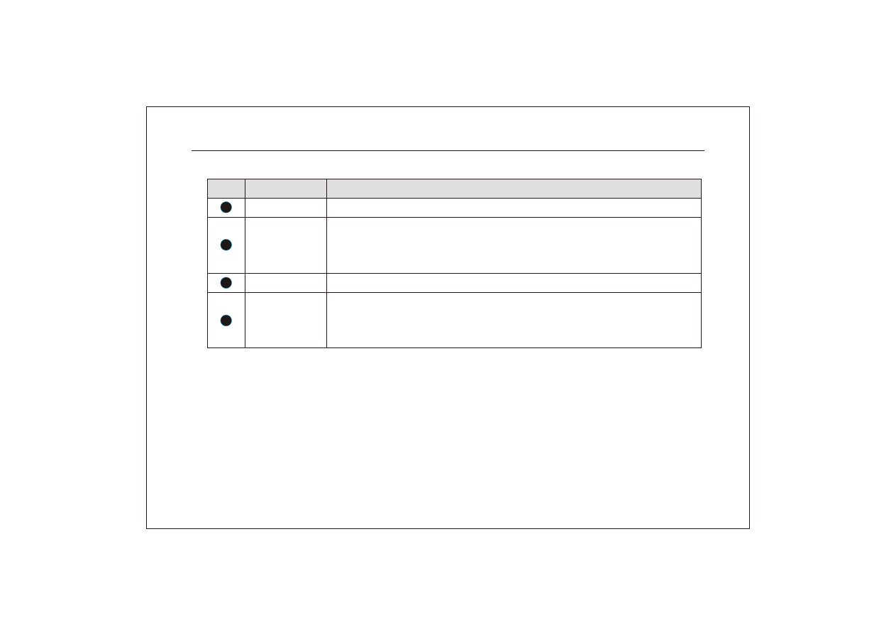
11
Description
Key Name
No.
Exit key
Press it to exit from the inferior menu and return to the superior menu.
Connected to U disk and used for system software upgrade or video file backup. In-
sert the U disk after turn off the DVR. Better not connect the mouse here, or the sy-
stem would be abnormal.
USB2.0 port
IR receiver
Status indicator
To show the working status of the DVR. "IR" is remote control operation indicator;
"LOCK" is panel lock indicator; "HDD" is hard disk indicator; "POWER" is power
indicator.
Receive signal from remote control.
8
9
10
Network Digital Video Recorder Operation Manual ( V1.0 )
10
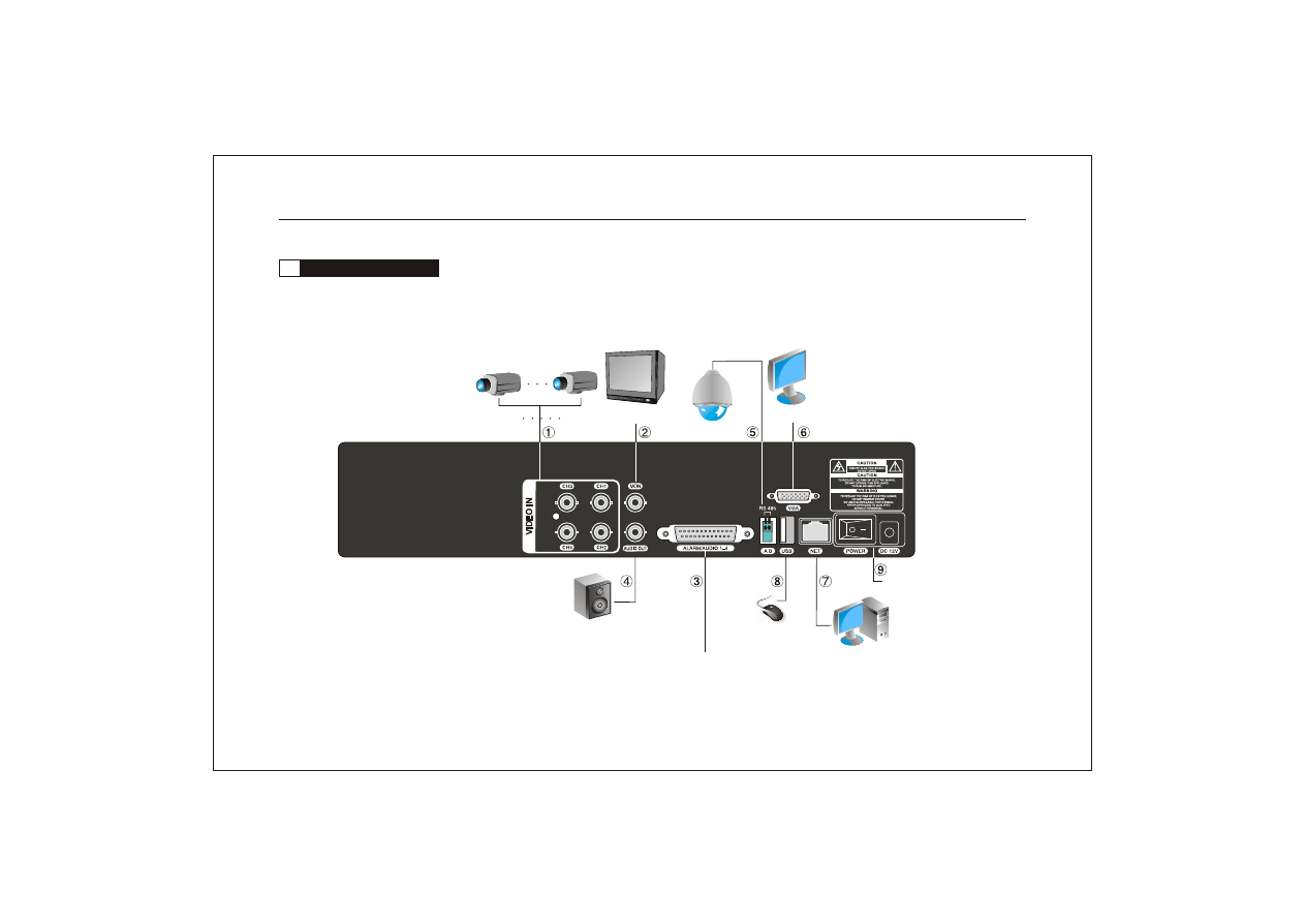
USB mouse
Alarm and audio input port
Camera4
Camera1
Network user
VGA Output
PTZ
Video output
Audio output
Rear panel of 4 channel H.264 DVR:
Power
Network Digital Video Recorder Operation Manual ( V1.0 )
11
2.2
Description of rear panel
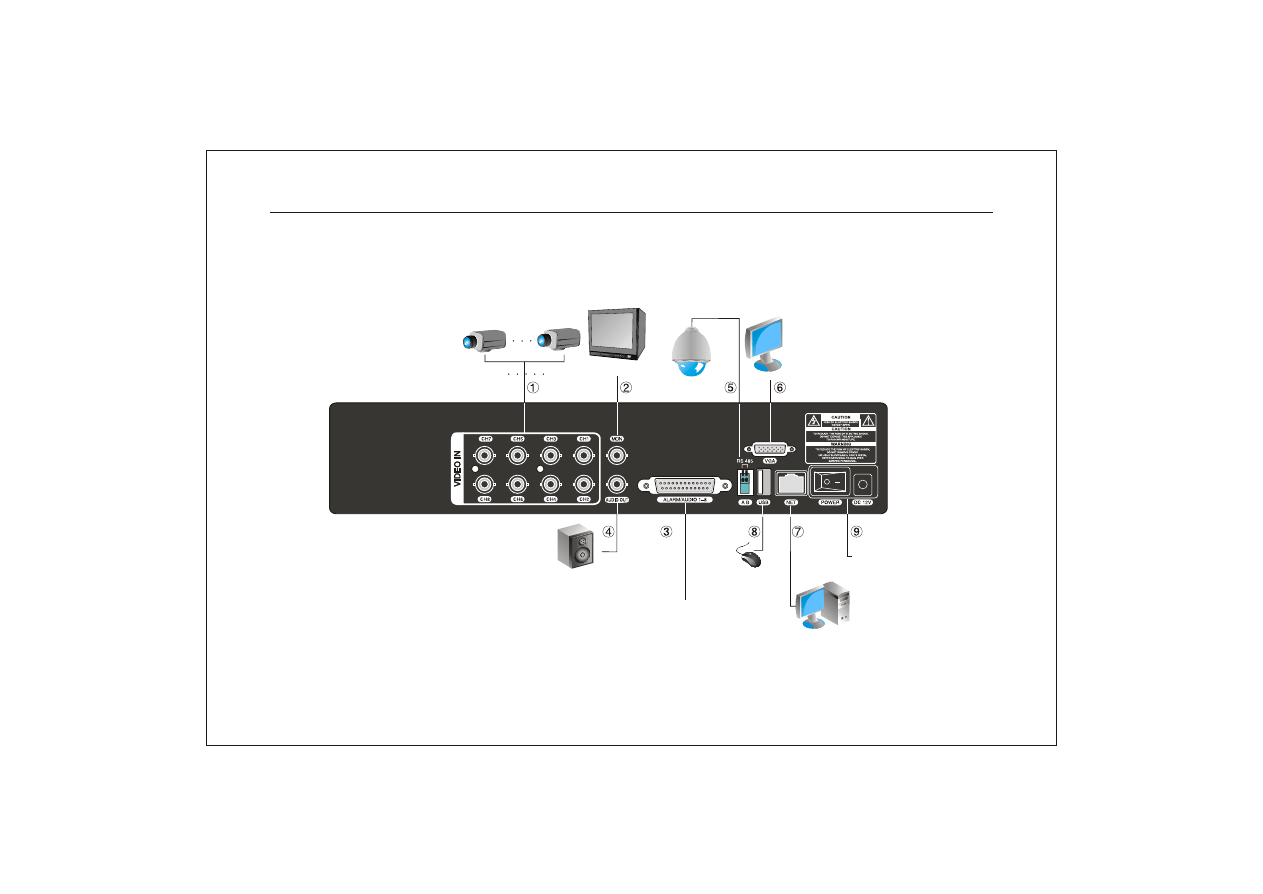
USB mouse
Camera8
Camera1
VGA Output
VGA Output
PTZ
Video output
Network user
Audio output
Rear panel of 8 channel H.264 DVR:
Alarm and audio input port
Power
Network Digital Video Recorder Operation Manual ( V1.0 )
12
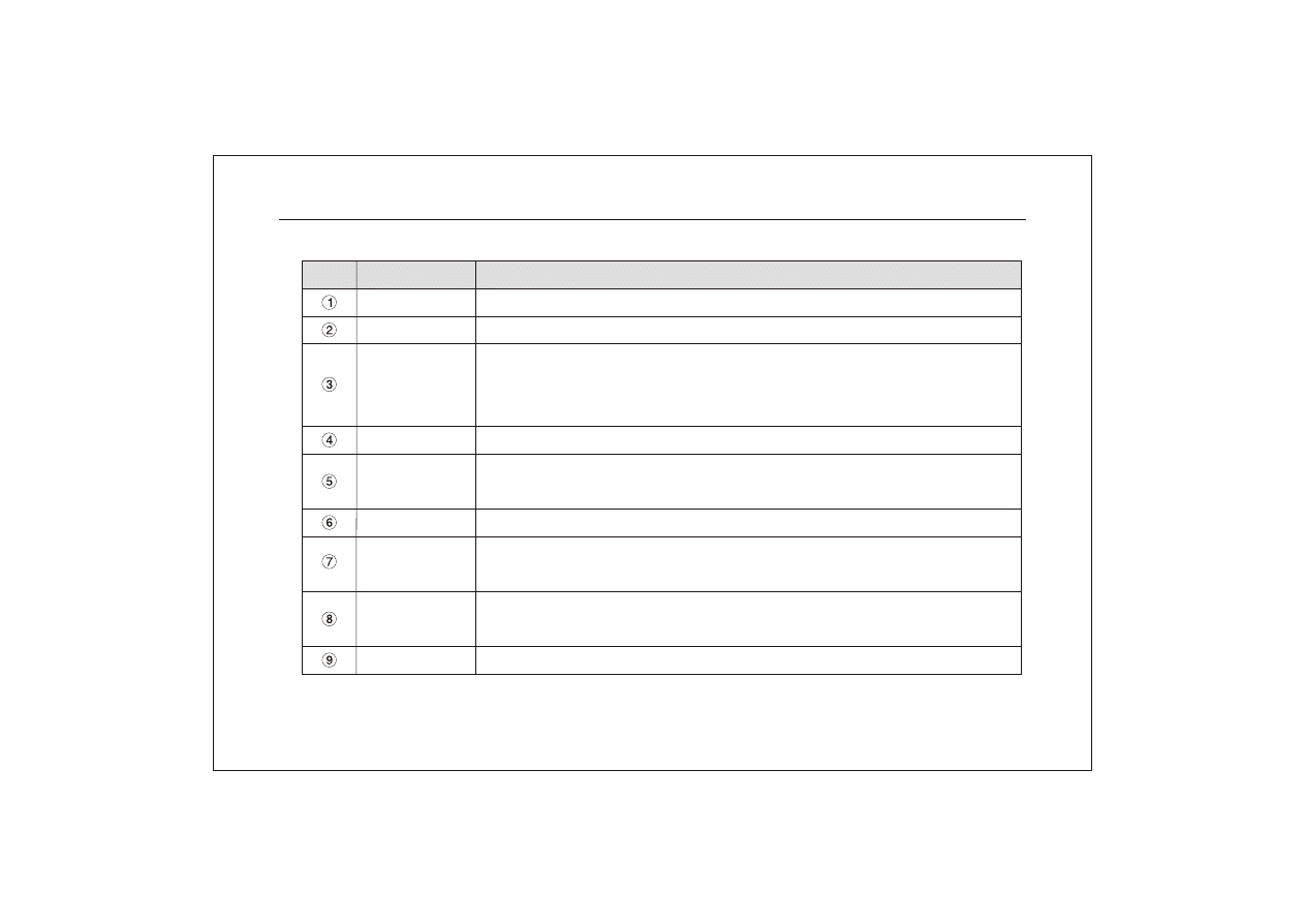
Description
Port
No.
Video input
Standard BNC port. connected with the Camera.
Connected with the video input of the monitor.
Video output
Audio output
Connected with earphone or cable speaker;
Alarm and
audio input port
Stanard AV port.
"NC/NO/COM": the alarm relay output. "NC" is normal close, "NO"is normal open,
"COM" is the public terminal.
"485"(AB)
RS484, it can connect PTZ or decoder, and canControl PTZ via the panel, mouse,
remote control and network.
VGA
VGA video signal output port, connected with the VGA port of a computer monitor.
NET
RJ-45 network port, connected to network cable and used for remote browse or control.
USB
connected to USB p endrive o r mouse and used for system software upgrade or video
file backup.
Power
DC power input, DC 12V/4A.
Network Digital Video Recorder Operation Manual ( V1.0 )
13
1
1
3
3
2
2
NC
NC
12V
12V
COM
COM
NO
NO
4
4
GND
GND
GND
GND
Alarm in
Alarm in
Audio input
Audio input
1
1
2
2
3
3
4
4
5
5
6
6
7
7
8
8
9
9
10
10
11
11
12
12
13
13
14
14
15
15
16
16
17
17
18
18
19
19
20
20
21
21
22
22
23
23
24
24
25
25
1
1
3
3
2
2
4
4
Alarm out
Alarm out
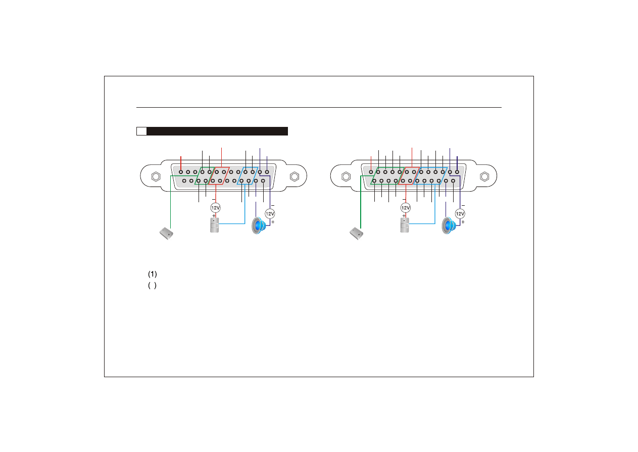
4 channel H.264 DVR alarm and audio port
8 channel H.264 DVR alarm and audio port
6
8
6
8
5
7
5
7
.
C/NO/COM : Alarm relay output. NC is normal close, NO is normal open, COM is the public terminal.
2 . GND : is ground. It means connected to the ground for alarm.
"N
"
"
"
2.3
Description of alarm and audio port in the rear panel
Prompt:
1. The power for alarm in and alarm out is DC12V.
2. To make the machine work well, please follow the above figures to connect.
Network Digital Video Recorder Operation Manual ( V1.0 )
14
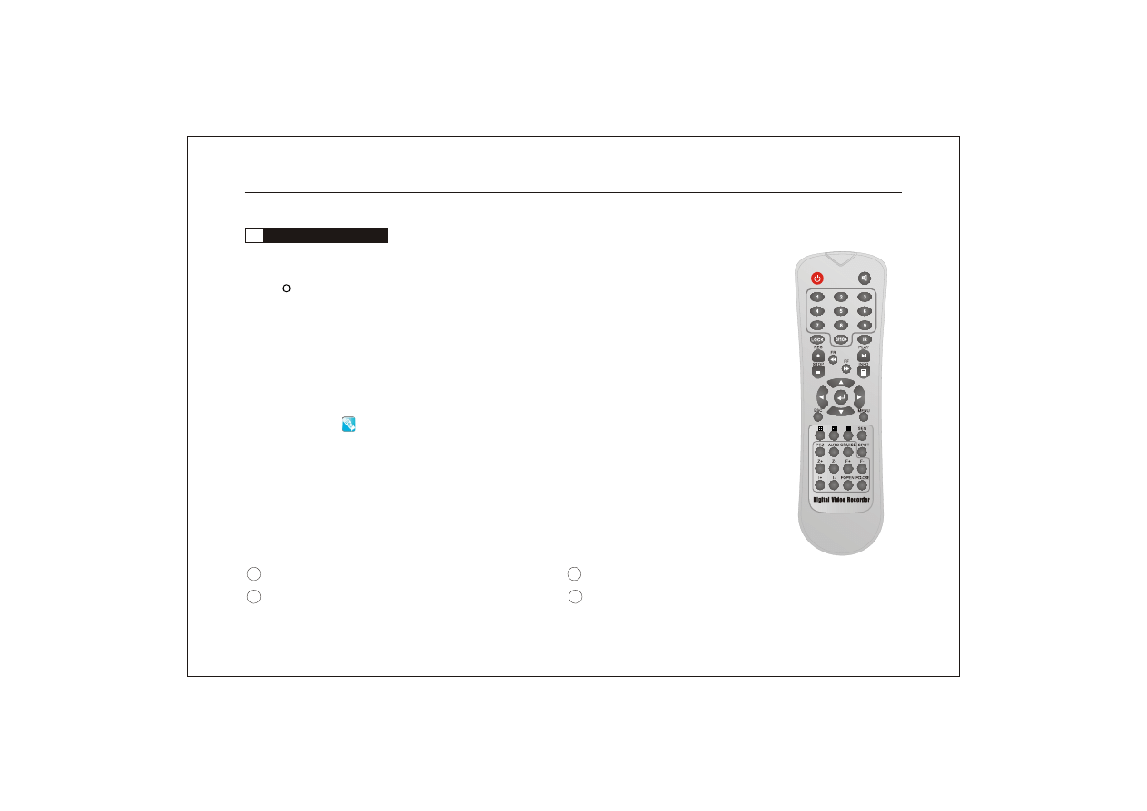
Before using it, please confirm that batteries have been installed correctly.
When using it, please aim IR TX (transmitter) of the remote control at IR reception of the DVR.
Then the IR light in the front panel is on and the icon on the top-right of the monitor screen
turns to blue " ".The DVR can be controlled by the remote control.
pen the battery cover, install two batteri es (Type No.7), make sure positive and negati ve
poles are right, then close the battery cover.
If the DVR can not be controlled by the remote control, please check the following aspects:
1 Check the positive and negative poles of the batteries. 2 Check the electric quantity of the batteries.
3 Check that whether Remote Sensor are blocked or not. 4 Whether Fluorescent lamps are being used or not nearby.
3. Trouble shooting
2.4
Remote control operation
1. Installing the remote control
2. Using the remote control
Note: If you don't want to use the remote control, you could set in the s ystem setup menu.
Set the item REMOTE ID as OFF. Then the IR Receiver light in the front panel
will be off and the operation of the remote control is invalid.
Network Digital Video Recorder Operation Manual ( V1.0 )
15
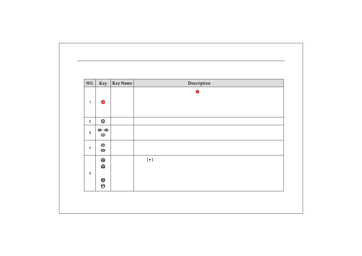
Audio
Number
Record
Play&pause
Stop
Info
Audio setup menu will pop up.
Select channels or set up password.
Input nunber 0.
Lock the machine or change the user.
Control the machine by remote control.
Lock
Remote ID
In normal running mode, press " " key to pop up a menu to prompt whether to
turn off. The DVR will be turned off and enter standby mode after "confirm " is
selected. The power light on the panel will turn green from red. Press the ke y
abour 3 seconds, the DVR will start.
Power
Press
key to enter record mode.
In live or record mode, press it to pop up search menu, select a video file to play. Pr-
ess it to play, press it again to pause.
Press it to stop playing.
Press it to pop up information menu.
1
9
Function description:
Network Digital Video Recorder Operation Manual ( V1.0 )
16
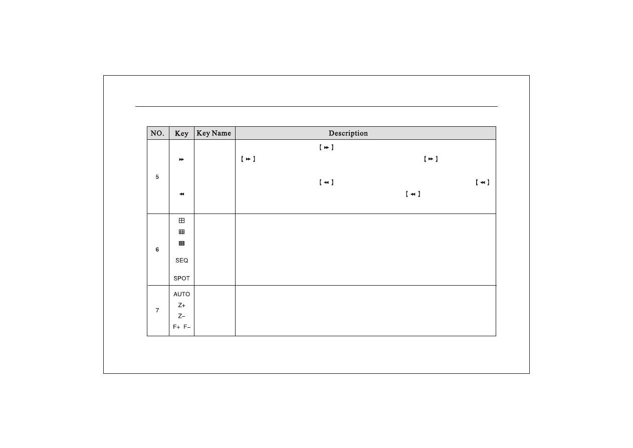
Quad
Sixteen-split
In playback mode, press
key to play images backward at 2 speed. Press
key again to play images backward at 4 speed. Press
key for the third
time to return to normal play mode.
In playback mode, press
key to play images forward at 2 speed. Press
key again to play imag es forwa rd at 4 speed. Press
key for the third time
to return to normal play mode.
Forward
Rewind
The monitor display quad-screen.
The monitor display nine-split-screen.
The monitor display sixteen-split-screen
In live preview mode, press this key to have the monitor automatically switching full
screen images of channels.
In PTZ control mode, press it to move the cursor among the digital in the screen.
Eight-split
Sequence
Spot output
AUTO
Zoom out
Zoom in
Focus
In PTZ control mode, this key is used to rotate PTZ automatically.
In PTZ control mode, this key is used to zoom out.
In PTZ control mode, this key is used to zoom in.
In PTZ control mode, "F+/F-" key is used to prolong/ shorten the focus.
Network Digital Video Recorder Operation Manual ( V1.0 )
17
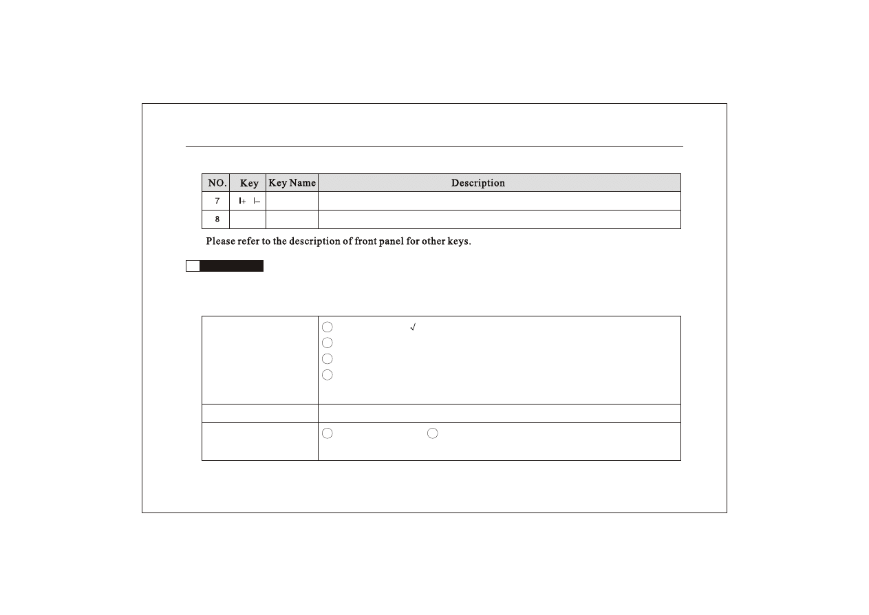
IRIS
In PTZ control mode, "I+/I-" key is used to enlarge/ reduce the iris (aperture).
Standby
2.5
Mouse operation
USB mouse can be used. Hot swap for mouse is supported. Move the mouse cursor onto the mouse icon to see
the name. Please insert the usb mouse into the usb port of the rear panel.
1 Select or cancel "
" in the item.
2 Input password in user log in interface.
3 Click the close icon on the top-right of the screen to exit from the main menu.
4 In split-screen mode, click one of the channels to make it full screen. Click it again
to return to split-screen. Switch single channel screens.
Left-click the mouse
Right-click the mouse
In live or playback mode, it could swich the single channel image.
Move the mouse
1 Move the cursor. 2 Move the cursor to the bottom of the screen to pop up the
mouse tool bar. Move the cursor onto the icon to show the name.
Network Digital Video Recorder Operation Manual ( V1.0 )
18
1 To select
shield
area in "Camera setup"
2 To select motion detection area in "Motion alarm".
Drag the mouse
To change the value or digital in menu mode.
Mouse wheels
Chapter III Menu Setup
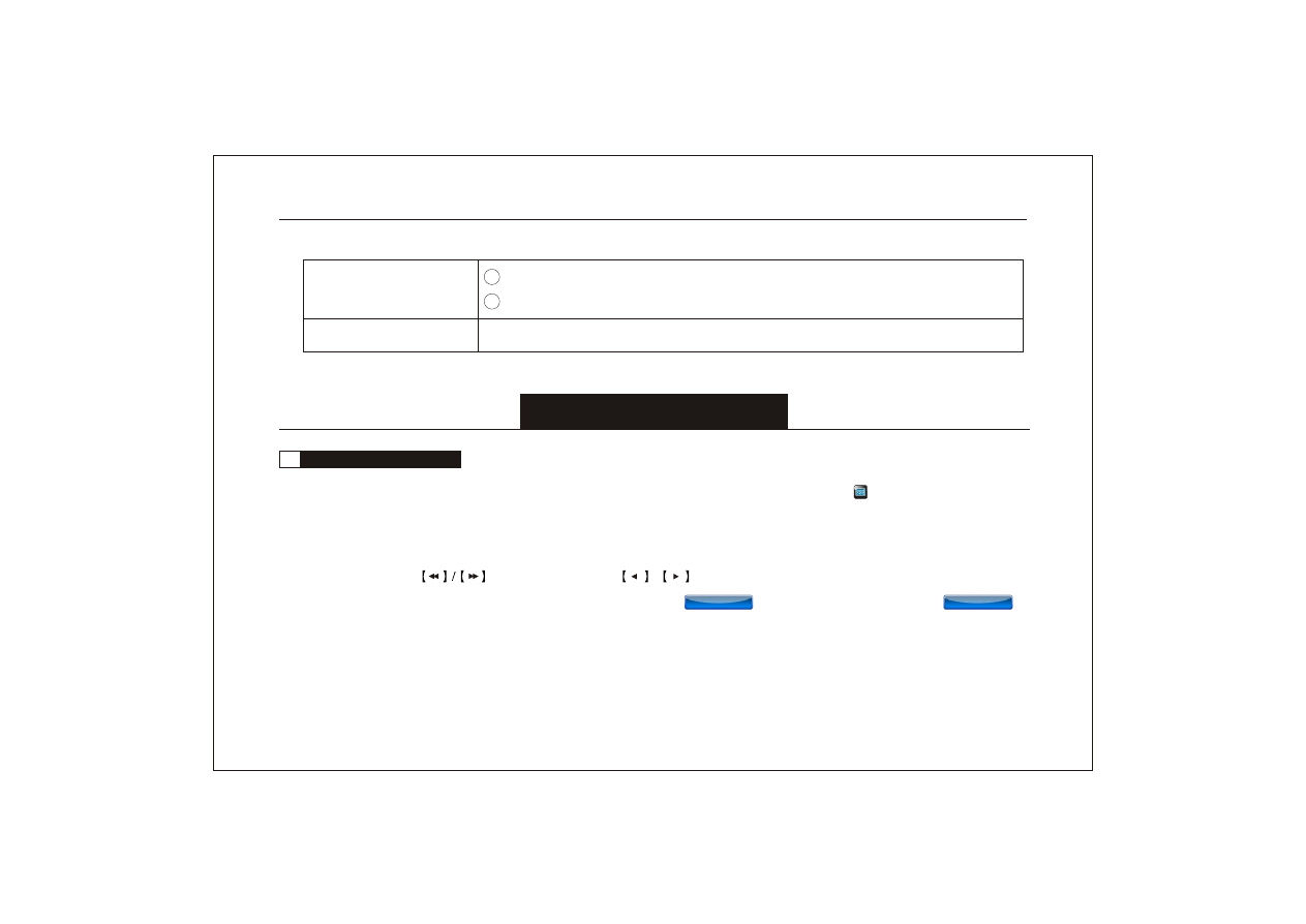
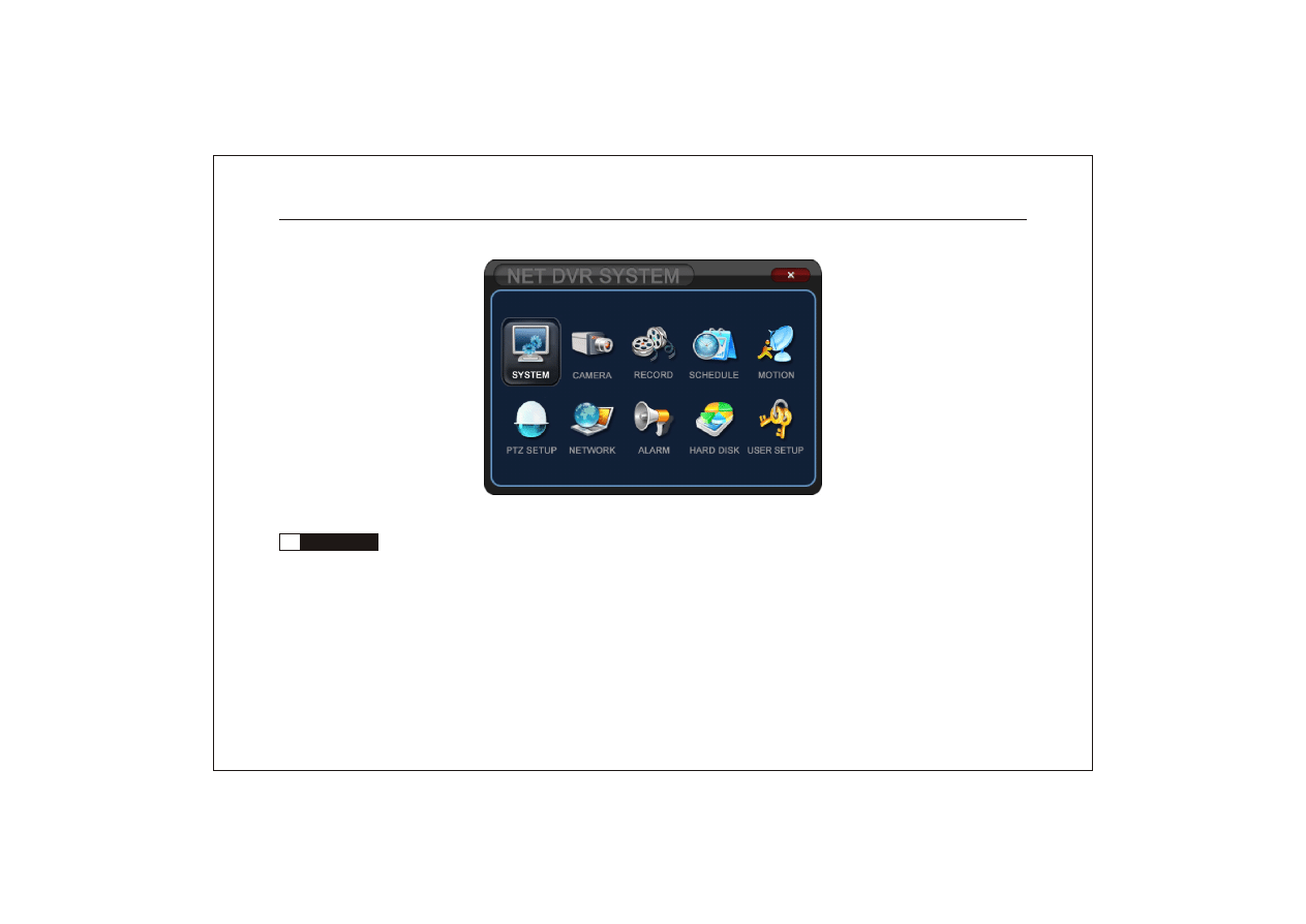
3.1
Summary of menu operation
In live preview mode, select "MENU" key on the remote control or the panel or click " " icon in mouse menu to
enter the main menu. Press "ESC" key or click the "close" icon that on the top right of the menu to exit from the main
menu.
Please press the
on the front panel or / key on the remote cntrol o r left/r ight-click with the
mouse to change the parameter value in the sub-menu. Click " " to save the value and click " "
to exit from the menu.
Network Digital Video Recorder Operation Manual ( V1.0 )
19
SAVE
SAVE
EXIT
EXIT
3.2
System setup
(1) Time setup: used to adjust the system date and time.
(2) Time format: used to set the format of date display, Asia/Europe/America are optional.
(3) Time DISP POS: display position of time and date, top middle / bottom middle / no display are optional.
(4) Border DISP: to select the color of borders, green/black/white/off are optional.
.
Main menu
Network Digital Video Recorder Operation Manual ( V1.0 )
20
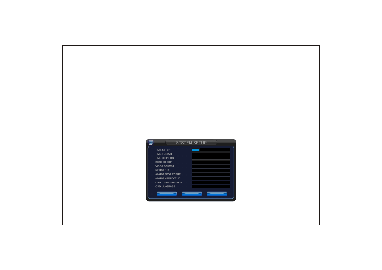
(5) Video format: to select the video mechanism, PAL/ NTSC are optional. The DVR system will be forced to restart
after switching
(6) Remote ID: used to set the remote control ID corresponding to the current machine so as to make remote control,
off/ on/ numbers from 0 to 9 are optional.
(7) Alarm spot up: on/off. Open or close the function.
(8) Alarm main pop up: on/off. Open or close the function.
(9) Transparency: set the transparency of the menu. The larger value, the higher transparency.
(10) OSD Language: display the language of the operating system.
2 0 0 9
/ 0 9 / 0 7 1 0 : 1 9
U . S . ( M M _ D D _ Y Y Y Y )
TO P M I D
G R E E N
PA L
O N
O F F
O F F
0
E N G L I S H
SAVE
SAVE
EXIT
EXIT
DEFAULT LOAD
DEFAULT LOAD
Network Digital Video Recorder Operation Manual ( V1.0 )
21
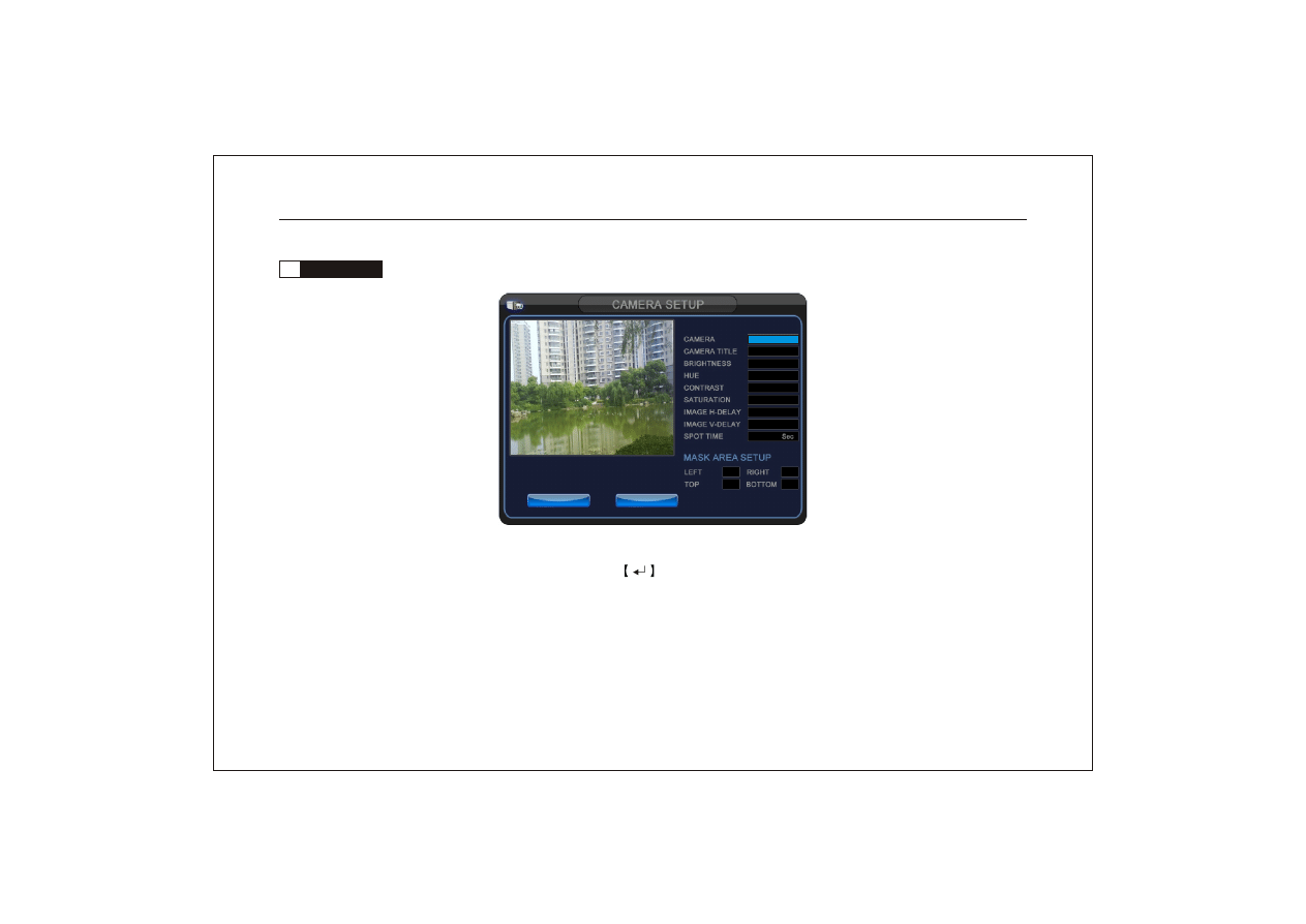
3.3
Camera setup
(1) Camera: used to select the channel to be revised parameters.
(2) Camera title: used to set the camera title. Press key in the front panel or remote control to turn into bitmap,
the camera title couldn't be changed.
(3) Brightness: used to adjust brightness of the channel. (4) HUE: used to adjust H ue (chro ma) of t he chann el.
(5) Contrast: used to adjust contrast of the channel. (6) Saturati on: used to adju st acuta nce of the channel.
(7) Mask area set up: Mask area: to shield some area by black square. It will turn to balck when surveillance or record.
C A M E R A 0 1
0 1
0 0
0 0
0 0
0 0
0 6
2 2
0 5
0 0 0
0 0 0
0 0 0
0 0 0
SAVE
SAVE
EXIT
EXIT
SAVE
SAVE
EXIT
EXIT
Network Digital Video Recorder Operation Manual ( V1.0 )
22
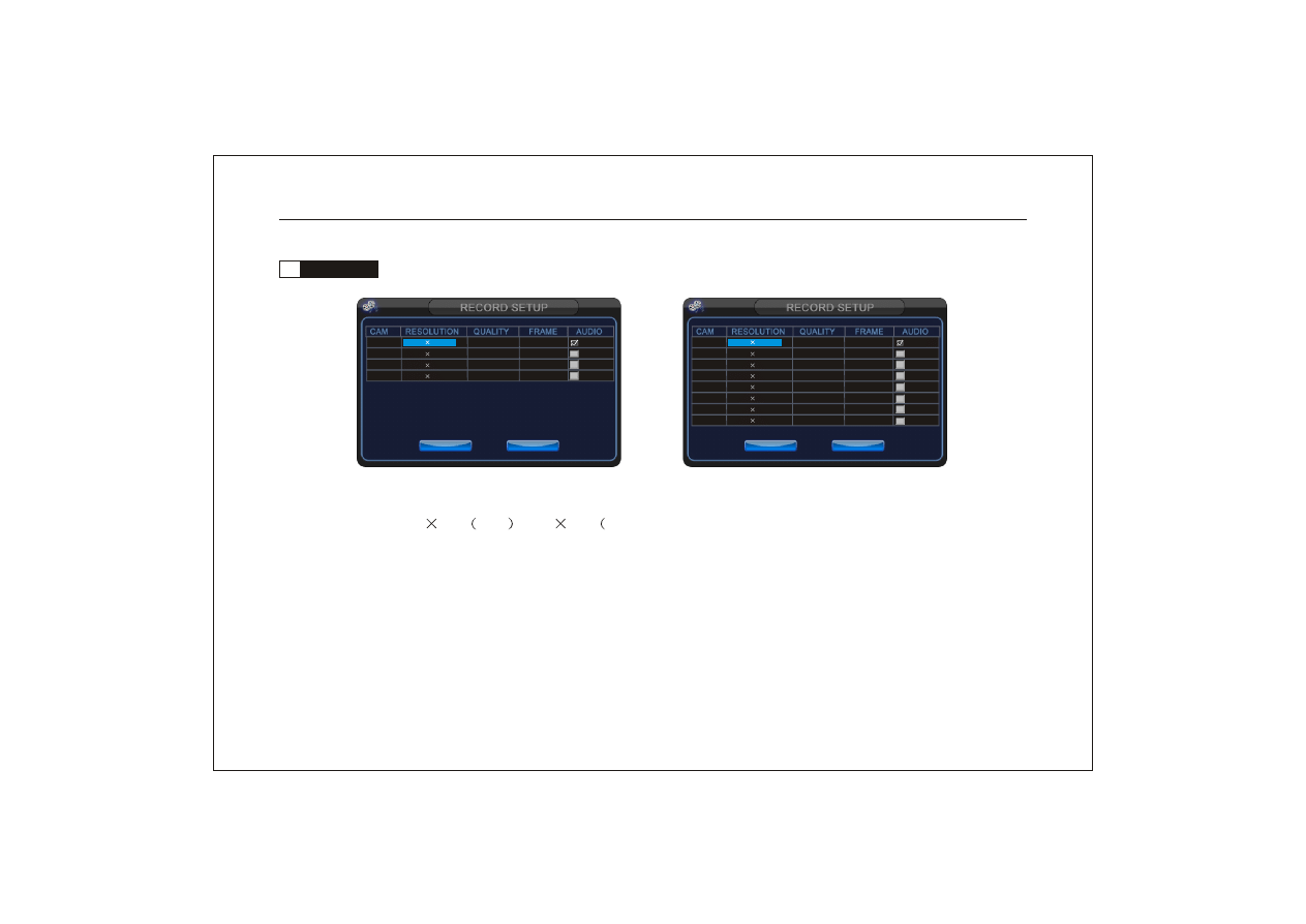
3.4
Record setup
Four channel DVR
Eight channel DVR
(1) Resolution: 352
288
PAL ; 352
240
NTSC. It can't be changed.
(2) Quality: the higher video quality, the larger occupied HDD space.
(3) Frame: used to set the quantities of images that recorded in one second. 25fps (PAL) and 30 fps ( NTSC) is real
time recording.
(4) Audio: used to turn on or turn off the audio record.
0 1
H I G H 2 5
3 5 2 2 8 8
0 2 3 5 2 2 8 8 H I G H 2 5
0 3 3 5 2 2 8 8 H I G H 2 5
0 4 3 5 2 2 8 8 H I G H 2 5
0 5 3 5 2 2 8 8 H I G H 2 5
0 6 3 5 2 2 8 8 H I G H 2 5
0 7 3 5 2 2 8 8 H I G H 2 5
0 8 3 5 2 2 8 8 H I G H 2 5
SAVE
SAVE
EXIT
EXIT
0 1
H I G H 2 5
3 5 2 2 8 8
0 2 3 5 2 2 8 8 H I G H 2 5
0 3 3 5 2 2 8 8 H I G H 2 5
0 4 3 5 2 2 8 8 H I G H 2 5
SAVE
SAVE
EXIT
EXIT
Network Digital Video Recorder Operation Manual ( V1.0 )
23
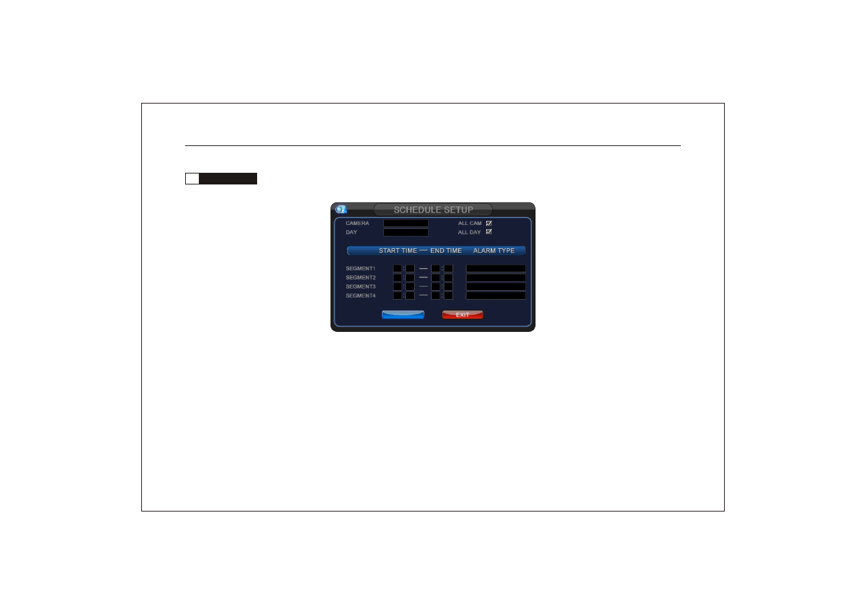
3.5
Schedule setup
(1) Camera: used to select the channel to be set. The parameters are effective for all channels after selecting" All CAM".
(2) Day: used to select the day of video schedule. The parameters are effective for all days after selecting "All DAY".
(3) Segment 1-4: set corresponding video type of relevant time range. The time could be set from 00:00 to 24:00.
Record type could be "time/alarm/motion/alarm+motion".
Notice: The start time cannot larger than the stop time, or it will report error and won't exit.
After exiting from this menu, please press "REC" key or click the record icon, or the schedule record
won't startup.
A L L
A L L
0 0 0 0
0 0 0 0
0 0 0 0
0 0 0 0
2 4 0 0
0 0 0 0
0 0 0 0
0 0 0 0
T I M E
T I M E
T I M E
T I M E
SAVE
SAVE
EXIT
EXIT
Network Digital Video Recorder Operation Manual ( V1.0 )
24
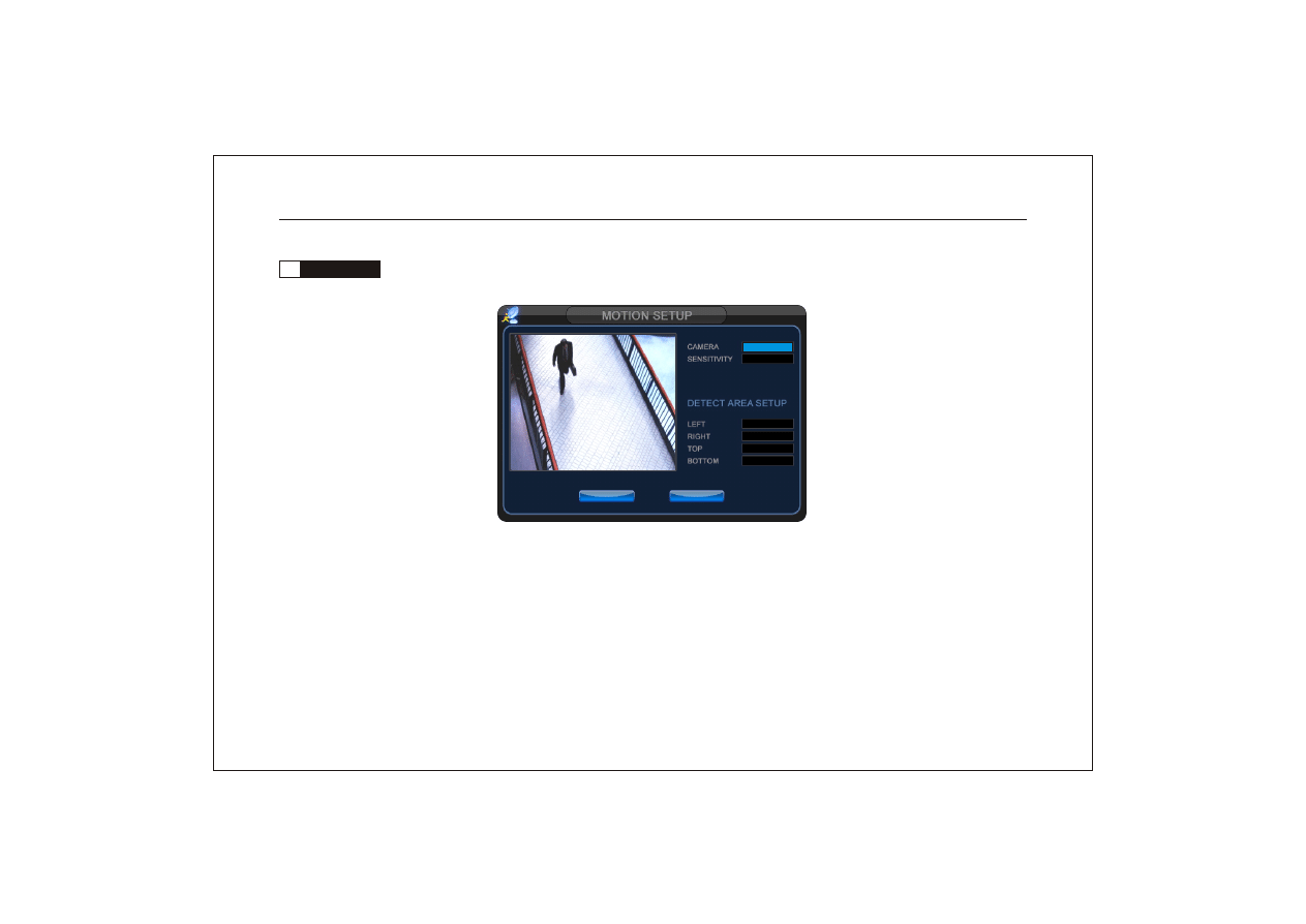
3.6
Motion alarm
(1) Camera: used to select the channel to be set.
(2) Sensitivity: high/low optional.
(3) Detect area setup: drag the mouse to set the detection area as light blue square. When motion occurs, the area
turn to red.
C A M E R A 0 1
0 0
0 0
0 0
0 0
0 0
SAVE
SAVE
EXIT
EXIT
Network Digital Video Recorder Operation Manual ( V1.0 )
25
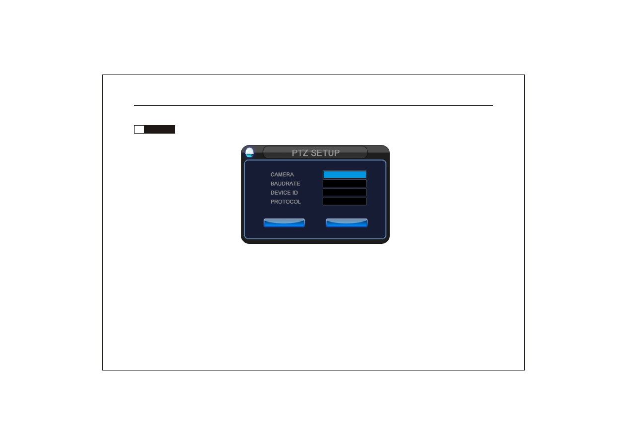
(1) Camera: to select the channel to be set.
(2) Baudrate: to set baudrate corresponding to the current channel PTZ.
(3) Device ID: to set ID address corresponding to the current channel PTZ.
(4) Protocol: set communication protocol corresponding to the current channel PTZ.
3.7
PTZ setup
Notice: the above parameters of each channel must be consistent with the setting of PTZ , or it cann't be
controlled.
C A M E R A 0 1
9 6 0 0
0 1
P E L C O _ D 2
SAVE
SAVE
EXIT
EXIT
Network Digital Video Recorder Operation Manual ( V1.0 )
26
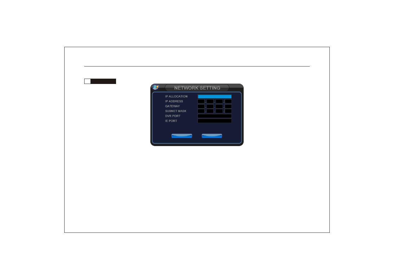
(1) IP allocation: static and DHCP/DDNS optional. (In static mode, please set IP address, gateway and subnet mask.
In DHCP mode, DVR could get IP from DHCP server.).
(2) IP address: It must be unique to avoid colliding with other DHCP.
(3) Gateway and subnet mask: Gateway is the LAN IP address of the router.
(4) DVR port: Transfer date stream, such as video and audio frequency.
(5) IE port: Download ActiveX control. (Default 0080).
3.8
Network setup
Notice: When using network browse, IP address/gateway/subnet mask/port of the DVR must be consistent
with the setting of the router.
SAVE
SAVE
EXIT
EXIT
D H C P / D D N S
1 9 2 1 6 8 0 0 1 2 0 7
1 9 2 1 6 8 0 0 1 0 0 1
2 5 5 2 5 5 2 5 5 0 0 0
6 8 0 2
0 0 8 0
Network Digital Video Recorder Operation Manual ( V1.0 )
27
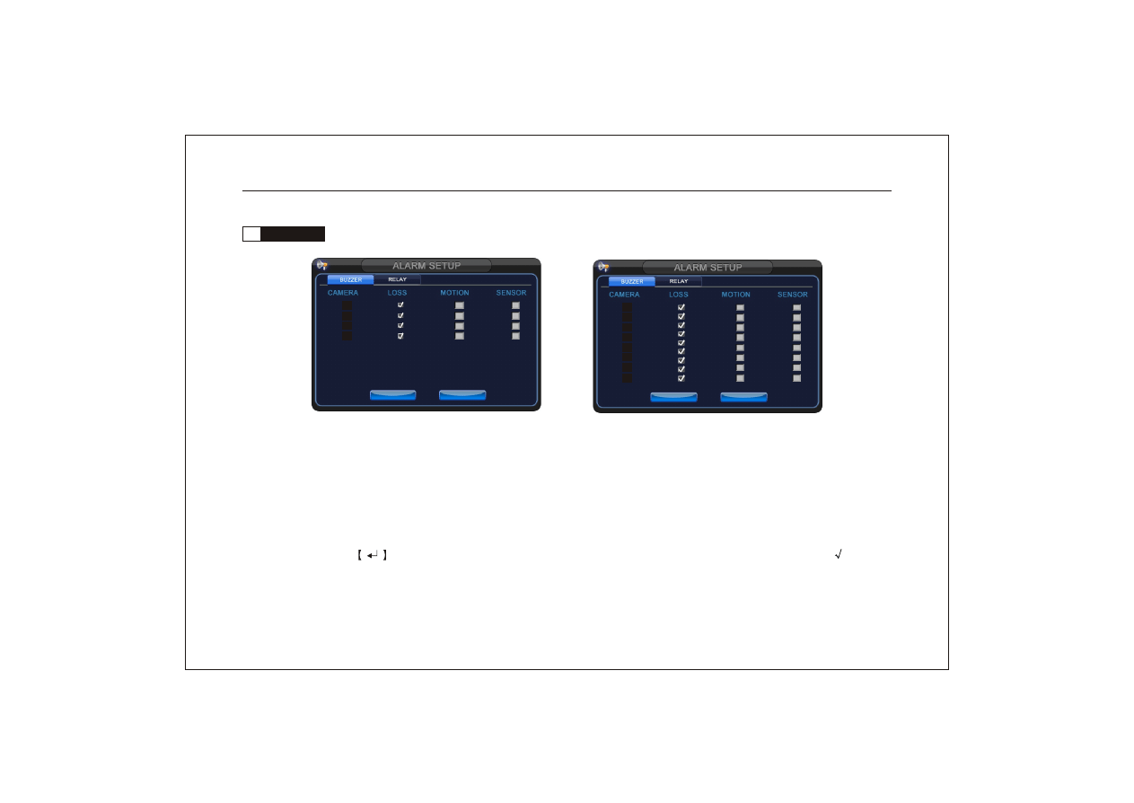
3.9
Alarm setup
There are two ways for alarm output, Buzzer and Relay. They include three alarm modes:
(1) Video loss alarm;
(2) Video motion detection alarm;
(3) Sensor input alarm.
Setup way: Press
key on the panel or remote control or click with the mouse to display or cancel "
" in the
small boxes.
0 1
0 2
0 3
0 4
SAVE
SAVE
EXIT
EXIT
0 1
0 2
0 3
0 4
0 5
0 6
0 7
0 8
SAVE
SAVE
EXIT
EXIT
Four channel DVR
Eight channel DVR
Network Digital Video Recorder Operation Manual ( V1.0 )
28
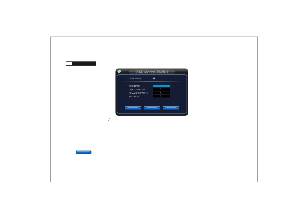
3.10
Disk management
(1) Overwrite: If click "
", the previous recorded video will be replaced in turn when the hard disc is full. If not,
record will stop. When you record again, the system will prompt: open overwrite function or for mat the har d disk.
(2) Disk name: select Disk. (3) Disk capacity: used to display capacity of the current disk.
(4) Remain capacity: used to display percentage of the remaining capacity of the current disk.
(5) Bad area: used to display bad size of the current disk.
(6) : used to format the current disk.
Prompt: You'd better format the hard disk before the first recording to protect the record video file.
D I S K A
0 7 4
0 9 9
0 0 0
SAVE
SAVE
EXIT
EXIT
FORMAT
FORMAT
FORMAT
FORMAT
Network Digital Video Recorder Operation Manual ( V1.0 )
29
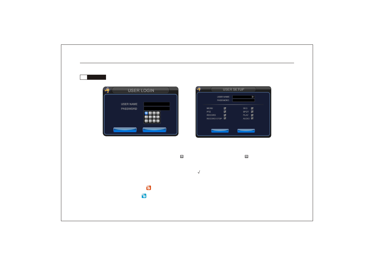
(1) User name: ADMIN0, USER01, USE02 and USER03 are optional and changeable. ADMIN0 is default adminis-
trator account.
(2) Password: set separate password for each user. " "is used to clear the former No. " " is used to clear all No..
Factory default setting: ADMIN:000000, USER01:111111, USER02:222222, USER03:333333.
(3) Permissions setup: set the operation permissions b y click"
" for users by admin. Use rs can't operate t he func-
tion which does note selected.
A D M I N
_ _ _ _ _ _
3.11
User setup
Password is needed to log in by admin.
A D M I N
_ _ _ _ _ _
Prompt: If the DVR is locked, " "will display in the top right of the screen. Click the icon to input password.
If the icon turns to " ", DVR is unlocked.
A D M I N 0
_ _ _ _ _ _
OK
OK
EXIT
EXIT
A D M I N 0
0 0 0 0 0 0
SAVE
SAVE
EXIT
EXIT
Network Digital Video Recorder Operation Manual ( V1.0 )
30
Please check whether the system connection is correct, input / output equipments are connected well and the power
supply is on before turning on DVR.
Please make sure video mechanism (PAL or NTSC) of video
input and mechanism of the monitor meet the r equi reme nts.
After checking without prob lems, plu g in the power cable of
DVR, then turn on the power switch on the rear panelof DVR.
The powe r indicat or light will turn red after normal starting of
DVR. If it is in video recording mode before turningoff last time,
it will resume video recording automatically.
Chapter IV Basic Operations
4.1
Turn on DVR
4.2
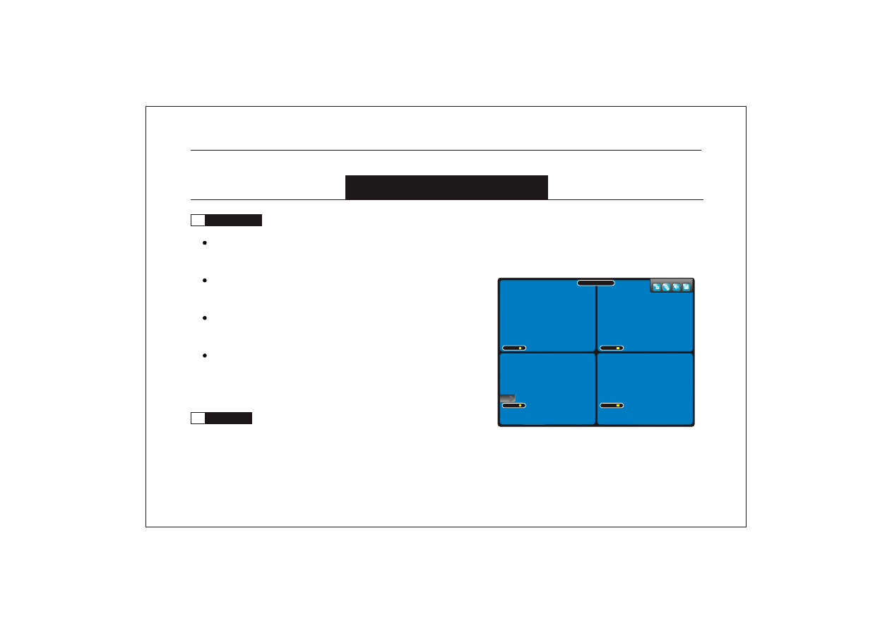
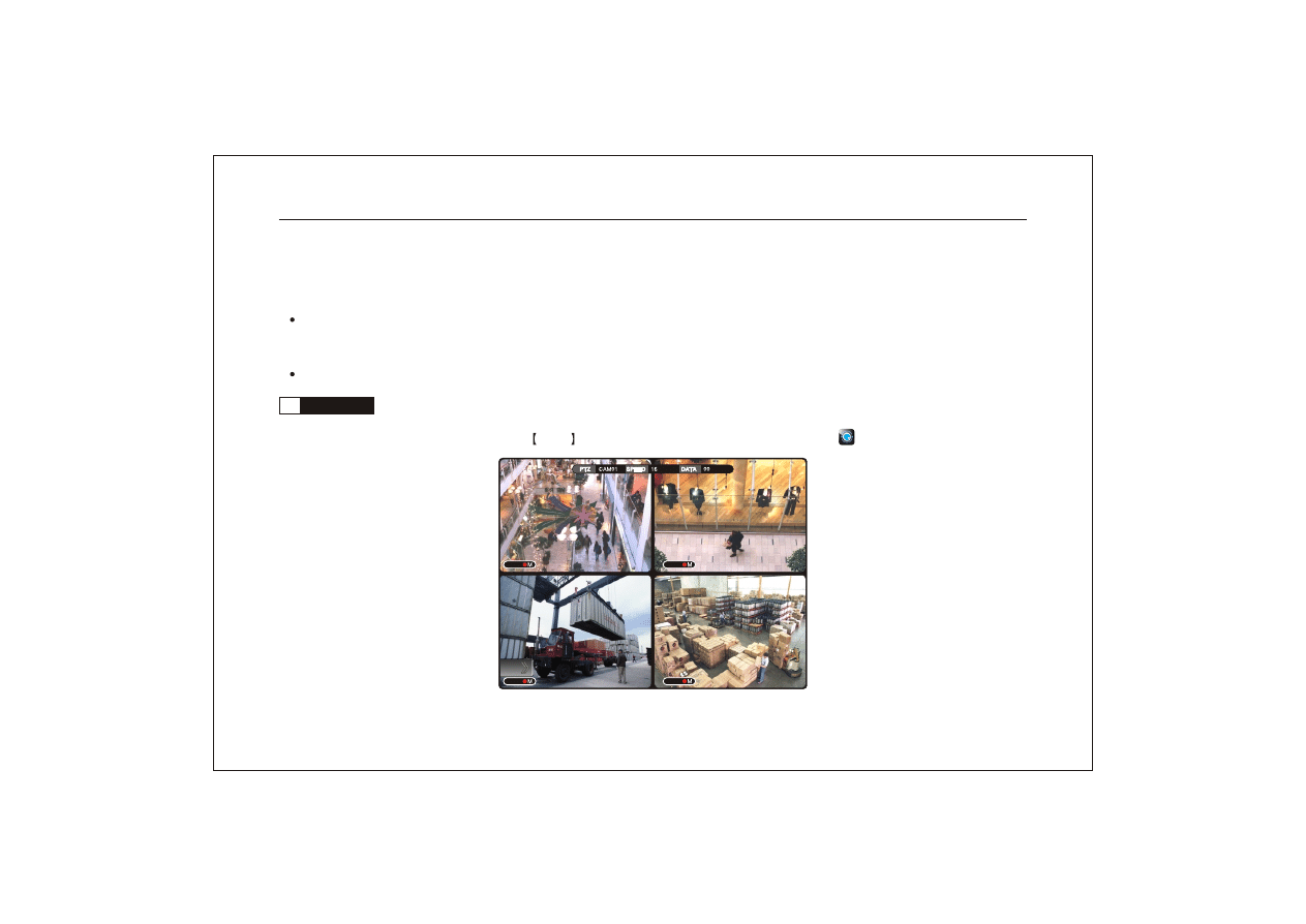
Live screen
(1) Turn on the DVR, you could see the live screen.If no video
input, the screen is as follows: (take 4 channel DVR as example.)
Network Digital Video Recorder Operation Manual ( V1.0 )
31
CH5
CH5
?
CH03
?
CH04
?
CH02
?
CH01
2009-09-02 12:23:18
(3)
Icons in top right of the screen:
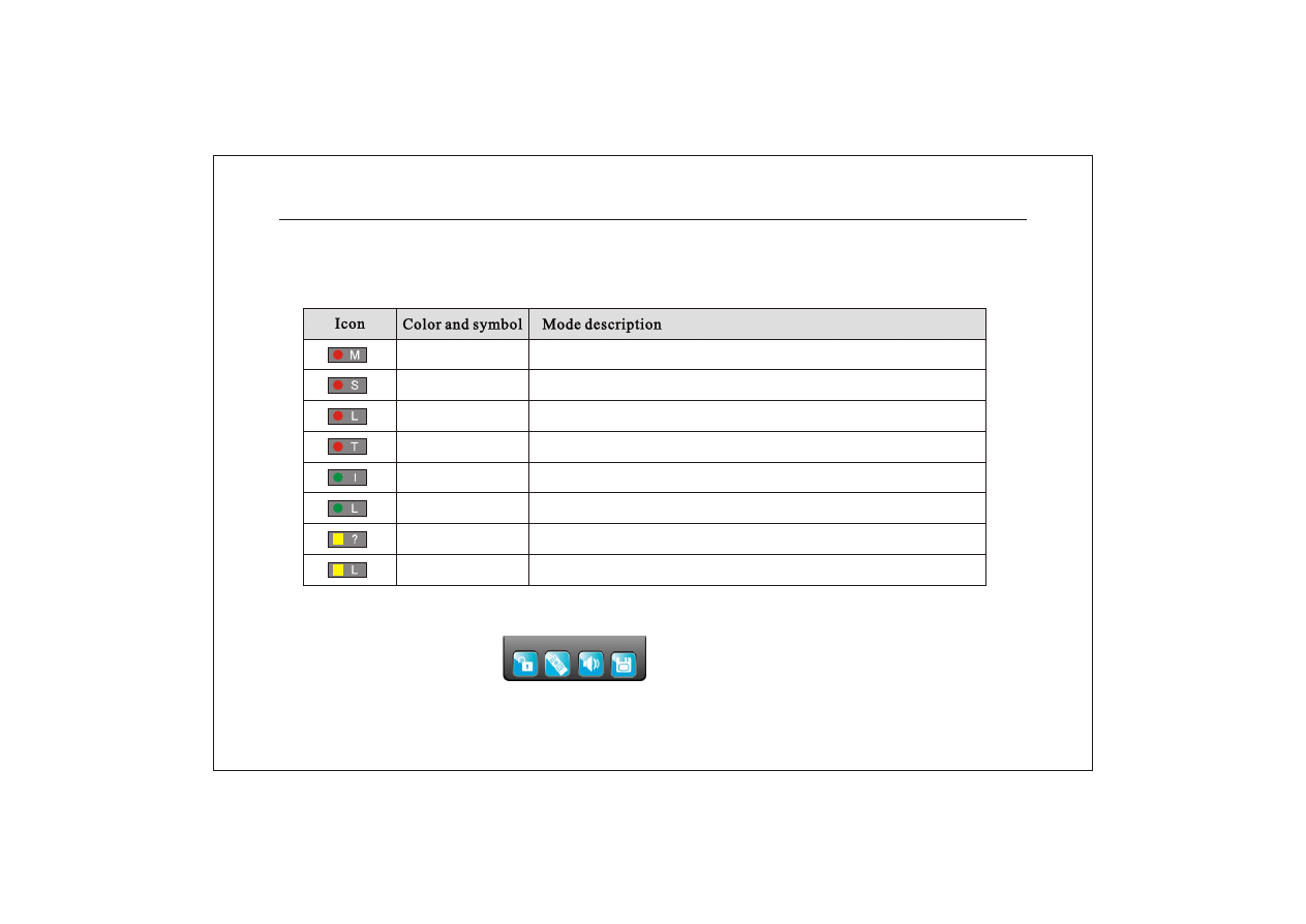
(2) Channel name and record mode icon display in the bottom left of each channel.
Description of record icon and mode:
Red M
Red S
Red L
Red T
Green I
Green L
Yellow ?
Yellow L
Is is recording by motion alarm.
It is recording by sensor alarm.
Image lost in the process of record.
It is recording by time.
DVR is waiting for video event triggered in auto recording mode.
Image lost in the process of waiting for record.
No record.
Image lost in no record mode.
Network Digital Video Recorder Operation Manual ( V1.0 )
32
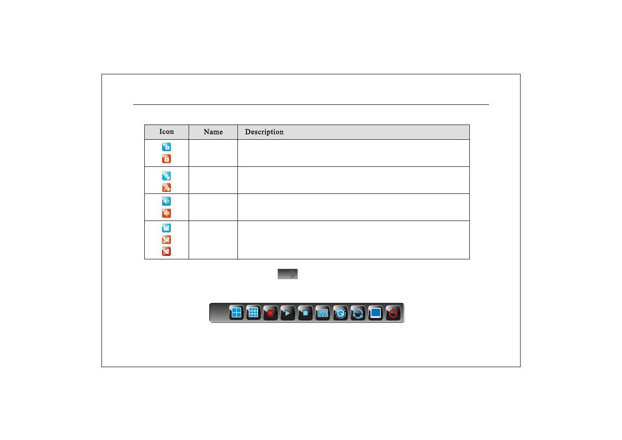
(4)
Move the mouse cursor to the icon
" "
in the bottom left of the screen. Mouse tool bar wi-
ll pop up as follows.
Lock
Remote IR
Audio
Infomation
Unlocked. Click it to lock.
Locked. Click it to login by inputting password.
Remote control is opened. Click it to close.
Remote control is closed. Click it to open.
Audio output is open. Click it to enter into audio setup menu.
Audio output is closed. Click it to enter into audio setup menu.
Hard disk is normal. Click it to pop up info menu.
Hard disk is full. Click it to pop up info menu.
No hard disk. Click it to pop up info menu.
Network Digital Video Recorder Operation Manual ( V1.0 )
33
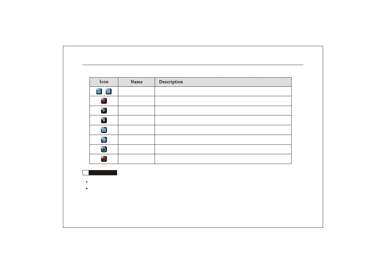
Split-screen
Record
Search&playback
Stop
Main menu
PTZ
SEQ
Power
Click it to display Quad and nine-split-screen.
Click it to starting recording.
Click it to enter the menu of search & playback.
Click it to stop recording or stop playing and return to the search menu.
Click it to enter into the main menu.
Click it to enter into PTZ control interface.
Click it to switch channels in sequence per 5 seconds.
Click it to pop up a menu for turning off the power or not.
4.3
Software update
Copy new version of the software to the root directory of USB pendrive, the file name is fireusb.
Turn off the DVR. Insert the USB pendrive with software into USB port in DVR front panel, then power on again.
20 seconds later, it will pop up "Software updating" and " Time: s" on the screen, the system update automatically.
When " update ok, reboot after 10 sec!" pop up on the screen, update is finished. Wait for 1 0 seconds , please pull
Network Digital Video Recorder Operation Manual ( V1.0 )
34
01
02
03
04
out the U disk and restart the machine. If " update fail, try again!" pop up more than 4 times, please contact after-
sales service department to deal with it.
In the process of update, please ensure no power breakdown and don't pull out USB pendrive, or update will be
unsuccessful.
Make sure U disk works in good condition so as to avoid abnormal performance in the process of update.
4.4
PTZ control
In live or recording mode,press PTZ key on remore control or click the icon " " in mouse menu to enter
PTZ control interface.
Network Digital Video Recorder Operation Manual ( V1.0 )
35
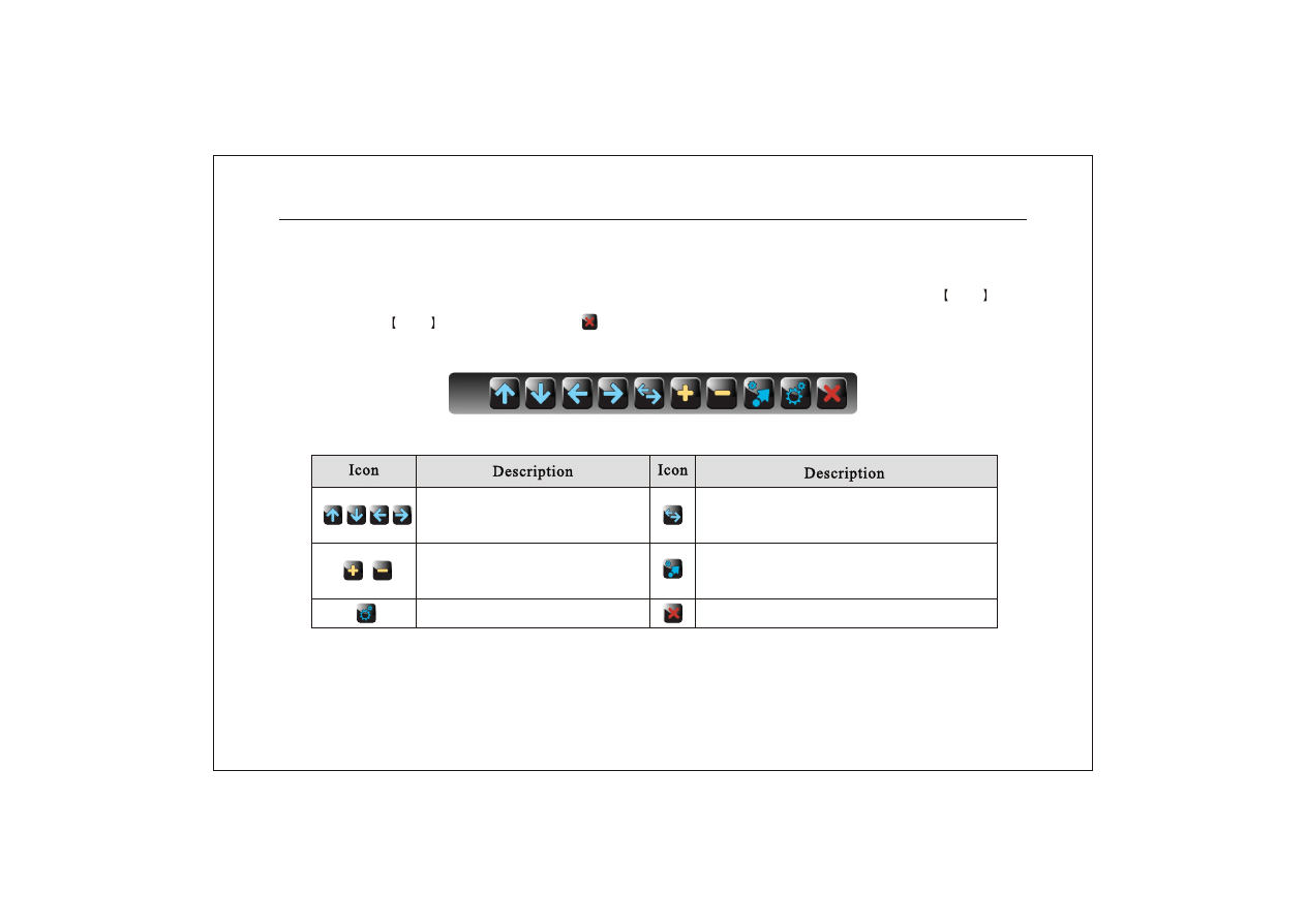
Characters "PTZ: CAM01 SPEED:01 DATA:01" display on the top of the monitor screen, indicating the DVR is un-
der PTZ control. PTZ control parameters of each channel can be modified in the system menu. Press PTZ key
again or press ESC key or click the icon " " to exit from PTZ control mode. When the mouse moved to the bo-
ttom of screen, it will display the following icons:
Please check the following table for the symbol of these icons:
Preset key
Direction icon. Control the camera
to turn right,left,up and down
Control the dome camra to rotate automatic-
ally. Click the icon again to stop it.
Zoom icon. Control the focal dista-
nce of zoom
Preview preset key
Shut off PTZ menu.And exit from PTZ control.
Modify the parameter:
When the cursor is on "PTZ:CAM01 SPEED:16 DATA:01", you could select camera,set the speed and preset
Network Digital Video Recorder Operation Manual ( V1.0 )
36
the data of image point. Select the item which need modify by pressing SPOT key on th e remote control or clic-
king the item directly with the mouse. Then change the data by pressing
on the remote control or
left/right-click with mouse.
Preset operations includes set and view
(1) Select image point in the selected camera by " " key, set a number for the image point in "DATA",
such as 01, then press
key on the remote control or click " " icon. Set is finished.
(2) To view of image point which has been preset,you could select the corresponding number in "DATA", then press
9ch split key
on remote control or click " " icon by mouse.
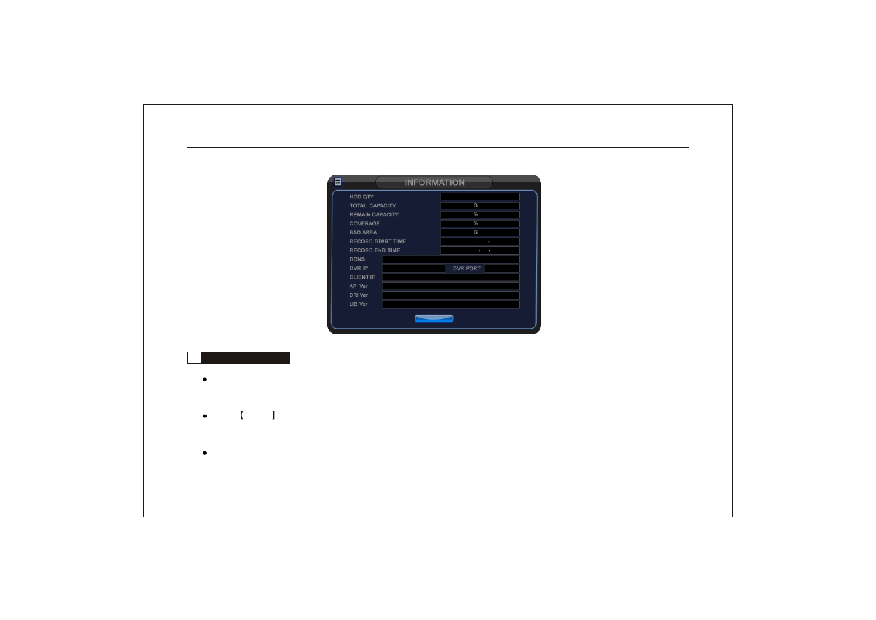
4.5
System information
Press INFO key or click the icon " " with mouse, it will display the interface of system informat ion as fo llowing.
(1) HDD QTY: the number of the hard drive which connected with the DVR
(2) Total capacity: total size of all hard drives in the DVR. DVD-RW not included.
(3) Remain capacity : percentage of the remain size of hard drive.
(4) Coverage: percentage of overwriting of hard drive. (5) Bad area: bad size of the hard drive.
(6) Record start time: the earliest record time. (7) Record ending time.
Network Digital Video Recorder Operation Manual ( V1.0 )
37
1
0 7 4
0 9 9
0 0 0
0 0 0
2 0 0 9 / 0 8 / 1 9 11
4 0
0 0
2 0 0 9 / 0 9 / 0 7 1 0
2 0
0 0
EXIT
EXIT
S e p 1 5 2 0 0 9 1 2 : 0 1 : 4 7
6 8 0 2
1 9 2 . 1 6 8 . 0 0 1 . 2 0 7
w w w. d v r s e r v e r. n e t : 2 5 A 0 0 0 1 @
S e p 1 4 2 0 0 9 1 6 : 0 5 : 0 8
S e p 1 2 2 0 0 9 0 2 : 3 2 : 3 9
4.6
Recording preparation
Make sure all the equipment is power on before recording. Make sure that there is video input and test audio in
put by live monitoring
Press INFO key to check disk information and the remaining capacity of the hard drive. If there isn't much
capacity left,pls firstly consider to replace hard drive, backup the video or overwrite the video.
If necessary, enter the "RECORD SETUP" to set audio recording,video i mage qua lity a nd recor ding frame rate.
Network Digital Video Recorder Operation Manual ( V1.0 )
38

If DVR is equiped se veral hard drive, please enter"DISK MANAGEMENT" t o check t he hard d rive information
by press
key in front panel or directly by mouse.
4.7
Recording operation
Firstly confirm that re cording m ode of ea ch channe l in schedule setup(timing,motion detection,alarm and motio-
n+alarm) and time segment setup.
Start record ing: Press the icon
on remote control o r front panel of DVR to start recording. Or click the icon
" " by mouse.
When DVR is under recording, you could select the recording cha nnel acco rding to fact so as to save more HDD
capacity.
It will be back to live when you press icon
on remote control and front panenl.Also you could click icon" "
by mouse to be back to live. Press ESC key and select " YES" to stop recording.
4.8
Search,playback and backup
Press
key or click" " icon in live or record mode to enter search menu.
(1) Valid time: from the time of recording start to the time of recording end.
(2) You could select one/two/three/four/five/six/seven/eight channels to playback at the same time as you like or si-
ngle channel to playback.
Network Digital Video Recorder Operation Manual ( V1.0 )
39
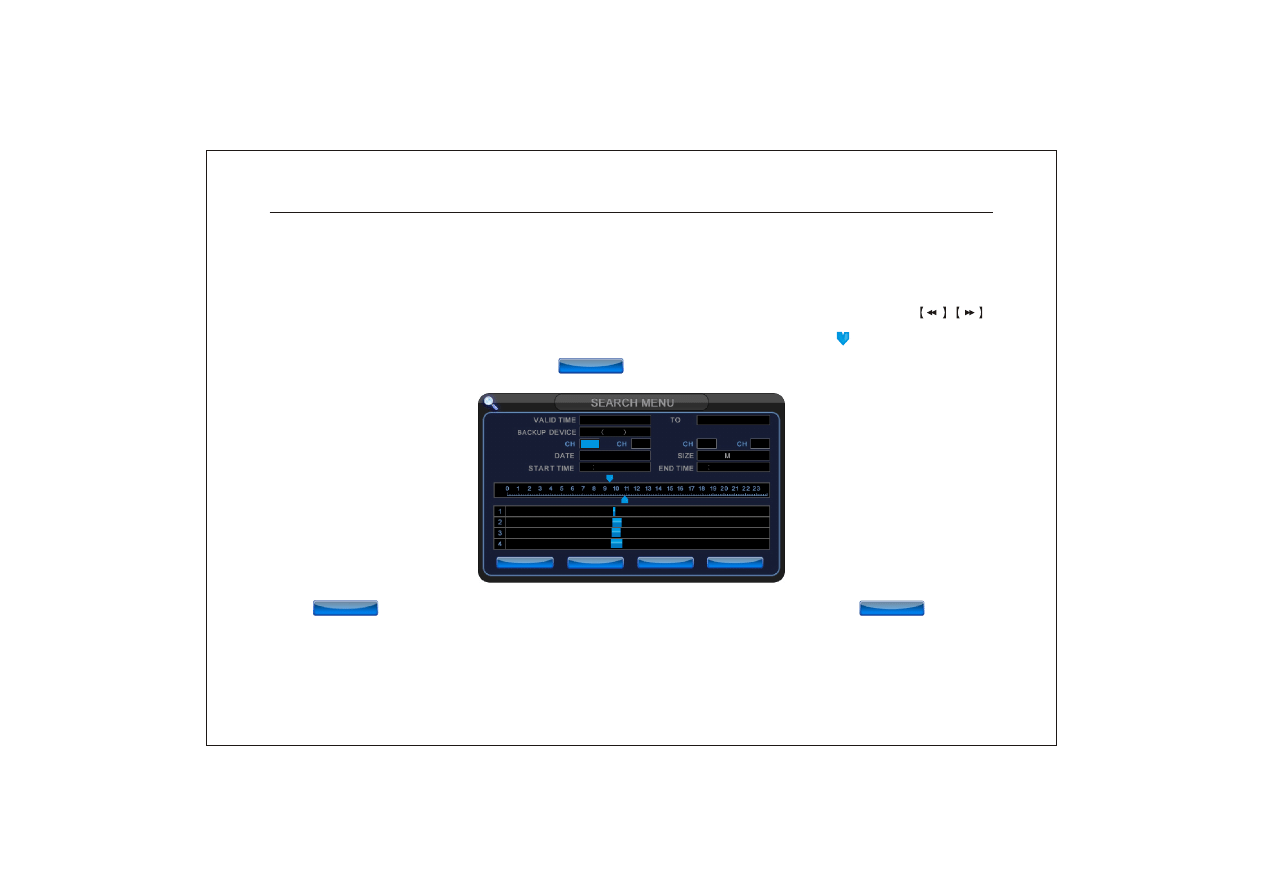
(3) Backup device: You culd select DVD-RW or USB pendrive in device item. The maximum capacity for DVD di-
sk should not exceed 1.5G.
(4) Playback: In option of date and start time ,input the date a nd time you need to play ,you could press the
key on remote control to playback the video. Or you could use mouse to drag the arrow " " und er th e time s cale
to select the start time, and click the icon " " to playback. When playback finshed, it will turn back to the
search menu automatically.
(5) : Before backup, please calculate the capacity of the video first. Click the icon " " to calc-
ulate the video you need to backup. If the video capacity is large, it will remind you waiting until
calculation finished.
Network Digital Video Recorder Operation Manual ( V1.0 )
40
0 1
0 2
0 3
0 4
2 0 0 9 / 0 9 / 1 7
2 0 0 9 / 0 8 / 1 9
2 0 0 9 / 0 9 / 0 7
D V D
1 . 5 G
9 5 5
1 0 5 5
BACKUP
BACKUP
PLAY
PLAY
PLAY
PLAY
EXIT
EXIT
CALCULATE
CALCULATE
CALCULATE
CALCULATE
CALCULATE
CALCULATE
(6) : Before backup,please connect the backup device to DVR, e.g. USB pendrive, USB HDD and CD-RW,
etc. You could select the time segment you need to backup with mouse. And click the " " icon
to start backup.The process will last for few minutes. When backup finished, please remove the device
from DVR.
(7) Plea se note t hat the size of video file should not exceed the maximum capacity of backup device . If system canno t
find backup device, it will be back to search menu.
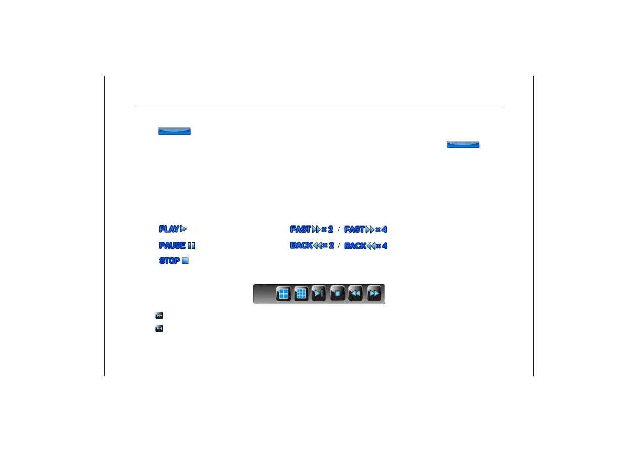
(8) On the bottom of screen, it will display the playback mode:
normal playback.
twice/ fouth time forward.
twice/fouth time rewind.
pause.
stop playback.
When you move the mouse cursor to the bottom of screen,it will display mouse icon while it is under playback:
" " click this icon to rewind when playback.
" " click this icon to forward when playback.
Network Digital Video Recorder Operation Manual ( V1.0 )
41
BACKUP
BACKUP
BACKUP
BACKUP
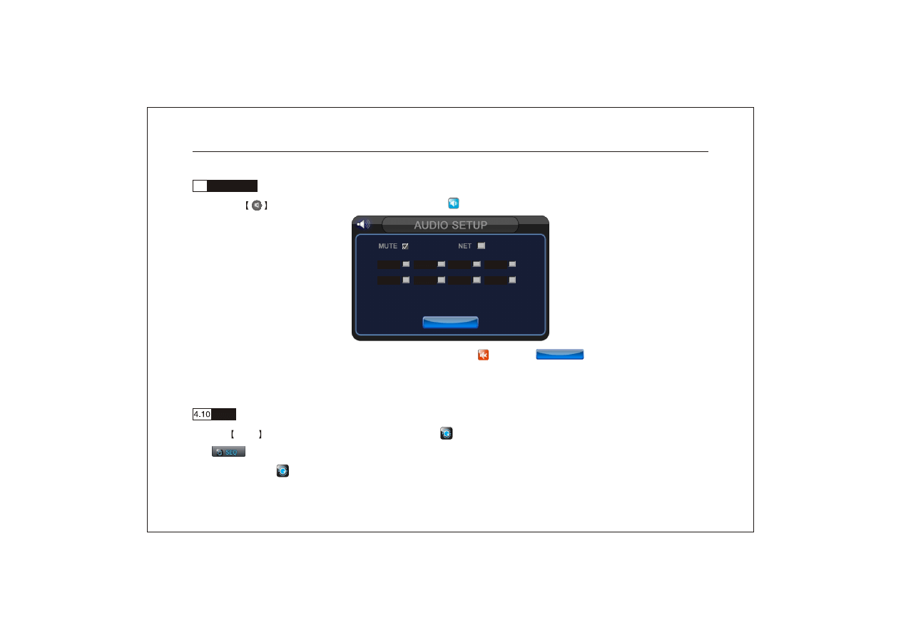
4.9
Audio setup
Press the
key on remote control or click the icon " " with mouse to enter audio setup interface.
(1) Mute: Make this selection and the audio icon will turn to " ". Press " " key to save this setup.
(2) Network:: make selection of network audio.
(3) It support 8ch audio input and 1ch audio output.
SEQ
Press SEQ key on remote control or click the icon " " .with mou se to sta rt SEQ. Th en it wil l display the ic on
" " on top right of screen. It will switch automatically between 1 channel, quad,8ch .The interval is5 second.
Click the icon " "with mouse to end SEQ.
Network Digital Video Recorder Operation Manual ( V1.0 )
42
C H 0 1
C H 0 2
C H 0 3
C H 0 4
C H 0 5
C H 0 6
C H 0 7
C H 0 8
ENTER
ENTER
ENTER
ENTER
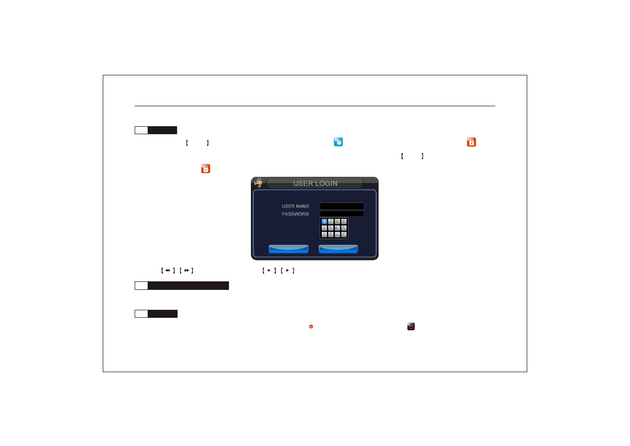
4.11
User login
Press the Lock key on remote control or click the icon " " with mouse, the icon wil l turn to red " " on
top right of screen. It means the system under lock condition. Then you need to press Lock key on remote control
or click the icon " " with mouse to enter user login interface.
Press
key on front panel or
key on remote control to select user name and in put pass word.
4.12
PC Client software instruction
You could control the DVR via client software on PC. Please refer to < client software instruction> attached in disk.
4.13
Power off
Normal power off: Stop all the operations, press " " on remote control or click " " icon on botto m lef t of
Network Digital Video Recorder Operation Manual ( V1.0 )
43
A D M I N 0
_ _ _ _ _ _
OK
OK
EXIT
EXIT
screen. And select "Confirm " to make it power off. When power off, the " Power " LED will turn green. If you
want to restart DVR, press the " " key with remote control for 3 second and it will power on.
Abnormal power off: Abnormal power off refer to shut off the power supply when it is running(especially
under recording). Please try your best to avoid such accident.
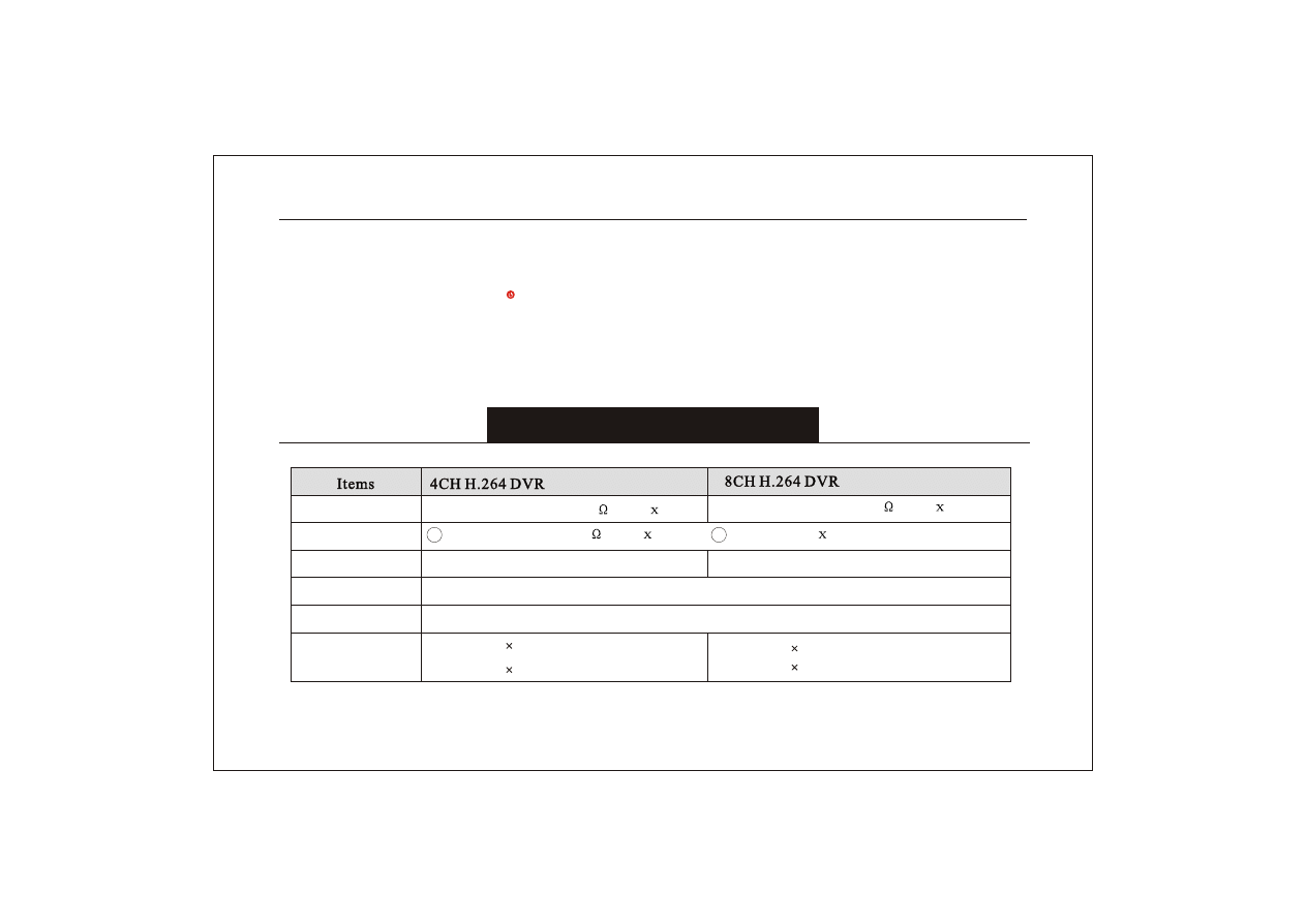
Appendix 1 Technical parameters
Video input
Video output
Alarm input
Alarm output
Alarm mode
Live frame rate
100fps 720 576(PAL)
120fps 720 480(NTSC)
200fps 720 576(PAL)
240fps 720 480(NTSC)
Alarm, motion detection,video loss,HDD full alarm
Relay output,NO,NC,COM
4ch optooupler input
8ch optooupler input
1 composite:1.0Vp-p/75
,BNC
1
4ch composite:1.0Vp-p/75
,BNC
4
8ch composite:1.0Vp-p/75
,BNC
8
2 VGA output
1
Network Digital Video Recorder Operation Manual ( V1.0 )
44
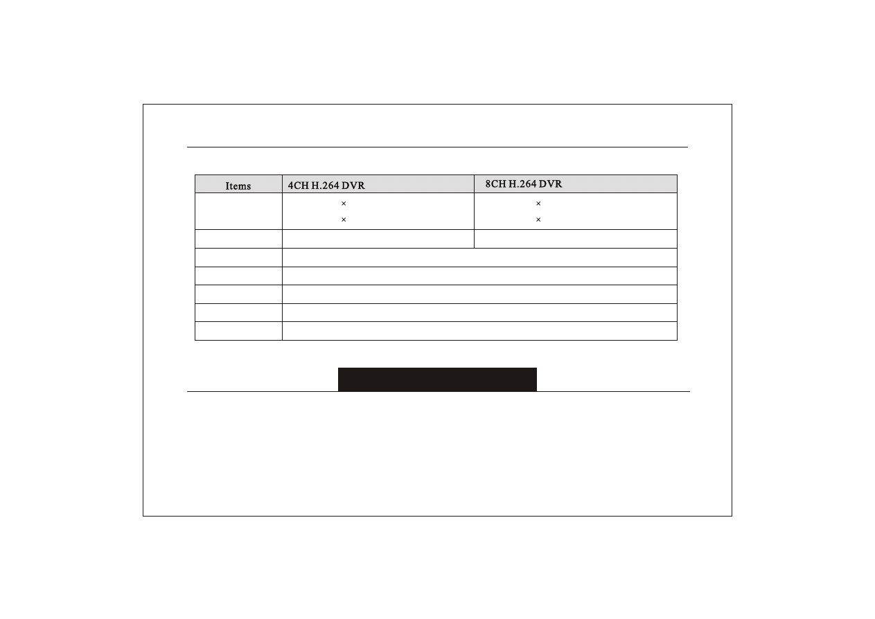
4ch audio input,1ch audio output
HOST 2.0
RS485
DC 12V/4A
Audio
Network interface
USB interface
HDDinterface
PTZ control
Power
SATA(Maximum capacity 1 Terabyte)
RJ-45 interface
8ch audio input,1ch audio output
Record frame rate
100fps 352 288(PAL)
120fps 352 240(NTSC)
200fps 352 288(PAL)
240fps 352 240(NTSC)
Appendix 2 Trouble shooting
1.Why cannot detect hard drive?
Default cause: The HDD power line or data cable is not connected well.
Resolution: Please check the power cable and data cable. And format the HDD.
FAQ :
Network Digital Video Recorder Operation Manual ( V1.0 )
45

2. Why the remote control not work? But the mouse is workable.
Default cause: The remote control ID was set "OFF" in system menu. Or it was set wrong ID.
3. Can we delete a part of video file in HDD?
No, it can't be done. For the reason of safty, we can't delete a part of video file in HDD. If you want to delete
them, please try to format HDD.
4. Why alarm is not workable?
Def ault caus e: 1 The schedule setup is wrong . 2 Alarm setup is wrong . 3 Alarm cable connection is wrong.
4 Alarm input signal is wrong. 5 It is not recording.
Network Digital Video Recorder Operation Manual ( V1.0 )
46
The operation manual is for reference only; products may vary.
Products are subject to update without further notice.
Please contact the customer service department for the latest program and supplementary information.
Any disputes or doubts in products description are subject to our final explanation.
Document Outline
- Ò³Ãæ 1
- Ò³Ãæ 2
- Ò³Ãæ 3
- Ò³Ãæ 4
- Ò³Ãæ 5
- Ò³Ãæ 6
- Ò³Ãæ 7
- Ò³Ãæ 8
- Ò³Ãæ 9
- Ò³Ãæ 10
- Ò³Ãæ 11
- Ò³Ãæ 12
- Ò³Ãæ 13
- Ò³Ãæ 14
- Ò³Ãæ 15
- Ò³Ãæ 16
- Ò³Ãæ 17
- Ò³Ãæ 18
- Ò³Ãæ 19
- Ò³Ãæ 20
- Ò³Ãæ 21
- Ò³Ãæ 22
- Ò³Ãæ 23
- Ò³Ãæ 24
- Ò³Ãæ 25
- Ò³Ãæ 26
- Ò³Ãæ 27
- Ò³Ãæ 28
- Ò³Ãæ 29
- Ò³Ãæ 30
- Ò³Ãæ 31
- Ò³Ãæ 32
- Ò³Ãæ 33
- Ò³Ãæ 34
- Ò³Ãæ 35
- Ò³Ãæ 36
- Ò³Ãæ 37
- Ò³Ãæ 38
- Ò³Ãæ 39
- Ò³Ãæ 40
- Ò³Ãæ 41
- Ò³Ãæ 42
- Ò³Ãæ 43
- Ò³Ãæ 44
- Ò³Ãæ 45
- Ò³Ãæ 46
- Ò³Ãæ 47
Wyszukiwarka
Podobne podstrony:
16 CH ENGLISH MANUAL(v1 0)
73 Varia B231 POL manual v1
English Billsburg v1 5
Mastech MS5908 english manual
73 Varia B231 POL manual v1
Tauris Club Manual v1 4US
Dongle User Manual V1 3
MoTomagx user manual v1 1
Auditor Pro Manual v1 0 5
MillipaK 4QPM Manual V1 01 (633T43801)
ITIL 2011 English glossary v1 0
TK200 English manual 20150206
MJoy16 C1 Users Manual v1
CCT DATE manual v1 0d
2700THX Stereo Power Amplifier English Manual
P2P Operation Manual V1 0 0 201406
Final Cartridge III english Manual
SpeedLink BT SL 8902 GY Manual V1 0
więcej podobnych podstron