

2/0

2/1
Contents
0
2
2 - Zelio Time - timing relays
Selection guide . . . . . . . . . . . . . . . . . . . . . . . . . . . . . . . . . . . . . . . . . . . . . page 2/2
1 Presentation . . . . . . . . . . . . . . . . . . . . . . . . . . . . . . . . . . . . . . . . . . . . . . page 2/4
1 Choice, functions . . . . . . . . . . . . . . . . . . . . . . . . . . . . . . . . . . . . . . . . . . . page 2/6
Modular relays, solid state output,
width 17.5 mm
1 Characteristics. . . . . . . . . . . . . . . . . . . . . . . . . . . . . . . . . . . . . . . . . . . . page 2/14
1 References . . . . . . . . . . . . . . . . . . . . . . . . . . . . . . . . . . . . . . . . . . . . . . page 2/16
Industrial single or multifunction relays,
solid state output, width 22.5 mm
1 Characteristics. . . . . . . . . . . . . . . . . . . . . . . . . . . . . . . . . . . . . . . . . . . . page 2/18
1 References . . . . . . . . . . . . . . . . . . . . . . . . . . . . . . . . . . . . . . . . . . . . . . page 2/20
Modular relays, relay output,
width 17.5 mm
1 Characteristics. . . . . . . . . . . . . . . . . . . . . . . . . . . . . . . . . . . . . . . . . . . . page 2/22
1 References . . . . . . . . . . . . . . . . . . . . . . . . . . . . . . . . . . . . . . . . . . . . . . page 2/24
Industrial single, dual or multifunction relays,
relay output, width 22.5 mm
1 Characteristics. . . . . . . . . . . . . . . . . . . . . . . . . . . . . . . . . . . . . . . . . . . . page 2/28
1 References . . . . . . . . . . . . . . . . . . . . . . . . . . . . . . . . . . . . . . . . . . . . . . page 2/30
Industrial single-function, relays, optimum,
relay output, width 22.5 mm
1 Characteristics. . . . . . . . . . . . . . . . . . . . . . . . . . . . . . . . . . . . . . . . . . . . page 2/42
1 References . . . . . . . . . . . . . . . . . . . . . . . . . . . . . . . . . . . . . . . . . . . . . . page 2/44
Universal plug-in relays, relay output, width 35 mm
1 Plug-in relays 11-pin
2 Characteristics . . . . . . . . . . . . . . . . . . . . . . . . . . . . . . . . . . . . . . . . . . page 2/48
2 References . . . . . . . . . . . . . . . . . . . . . . . . . . . . . . . . . . . . . . . . . . . . page 2/50
1 Plug-in relays 8-pin
2 Characteristics . . . . . . . . . . . . . . . . . . . . . . . . . . . . . . . . . . . . . . . . . . page 2/52
2 References . . . . . . . . . . . . . . . . . . . . . . . . . . . . . . . . . . . . . . . . . . . . page 2/54
Miniature plug-in relays, relay output
1 Characteristics. . . . . . . . . . . . . . . . . . . . . . . . . . . . . . . . . . . . . . . . . . . . page 2/56
1 References . . . . . . . . . . . . . . . . . . . . . . . . . . . . . . . . . . . . . . . . . . . . . . page 2/57
Electronic relays, relay output, 48 x 48 housing
1 Presentation, description, characteristics, functions . . . . . . . . . . . . . . . page 2/58
1 References . . . . . . . . . . . . . . . . . . . . . . . . . . . . . . . . . . . . . . . . . . . . . . page 2/63
Panel-mounted, plug-in, universal relays
1 Characteristics. . . . . . . . . . . . . . . . . . . . . . . . . . . . . . . . . . . . pages 2/66 and 2/70
1 References . . . . . . . . . . . . . . . . . . . . . . . . . . . . . . . . . . . . . . pages 2/69 and 2/71
2/2
2
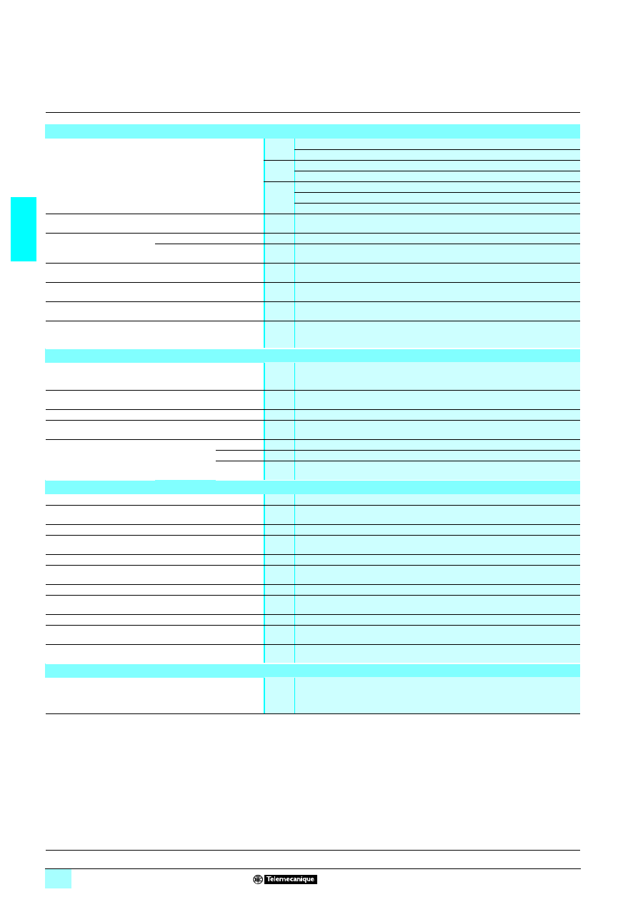
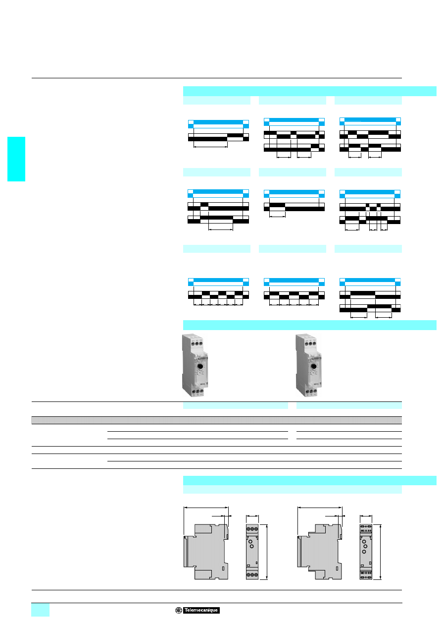
Selection guide
2
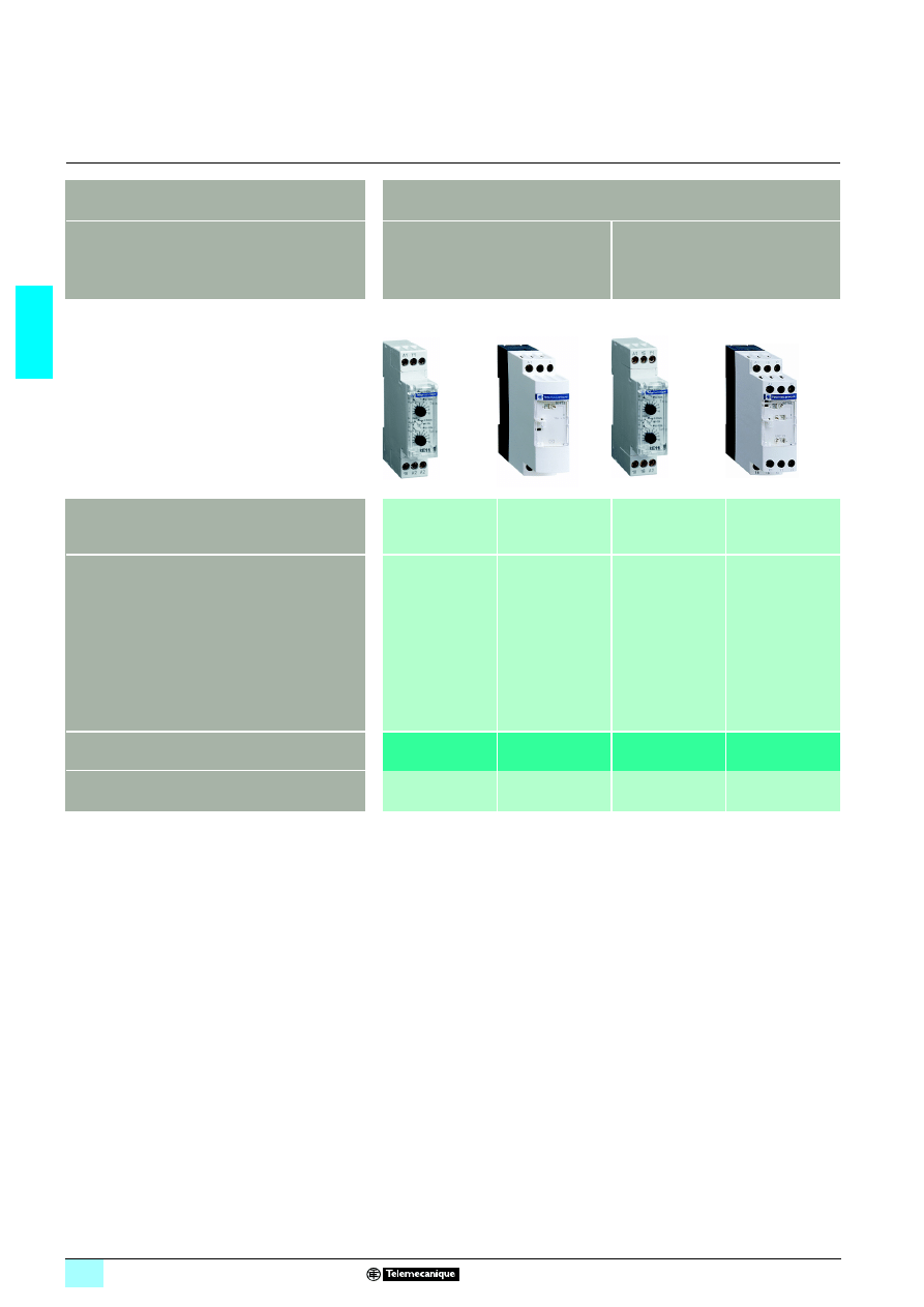
Zelio Time - timing relays
2
Applications
These timing relays enable simple automation cycles to be set up using wired logic.
They can also be used to complement the functions of PLCs.
Output
Solid state
Timing relays with solid state output reduce
the amount of wiring required (wired in
series). The durability of these timing relays
is independent of the number of operating
cycles.
Relay
Relay outputs provide complete isolation
between the supply and outut circuits.
It is possible to have several output circuits.
Type
Modular
Industrial
Modular
Industrial
Timing ranges
7 ranges :
1 s, 10 s, 1 min, 10 min,
1 h, 10 h, 100 h
1 or 2 ranges,
depending on model :
10 s, 30 s, 300 s,
60 min
Depending on model :
6 ranges :
1 s, 10 s, 1 min, 10 min,
1 h, 10 h
7 ranges :
1 s, 10 s, 1 min, 10 min,
1 h, 10 h, 100 h
Depending on model :
4 ranges :
0.6 s, 2.5 s, 20 s, 160 s
7 ranges :
1 s, 10 s, 1 min, 10 min,
1 h, 10 h, 100 h
7 ranges :
1 s, 3 s, 10 s, 30 s,
100 s, 300 s, 10 min
10 ranges :
1 s, 3 s, 10 s, 30 s,
100 s, 300 s, 30 min,
300 min, 30 h, 300 h
Relay type
RE11 L
1211
RE9
RE11 R
1211
RE 88 865
111
RE7
Pages
2/16 and 2/17
2/20
2/24 to 2/27
2/30 to 2/33
and 2/36 to 2/39
2/3
2
2
2
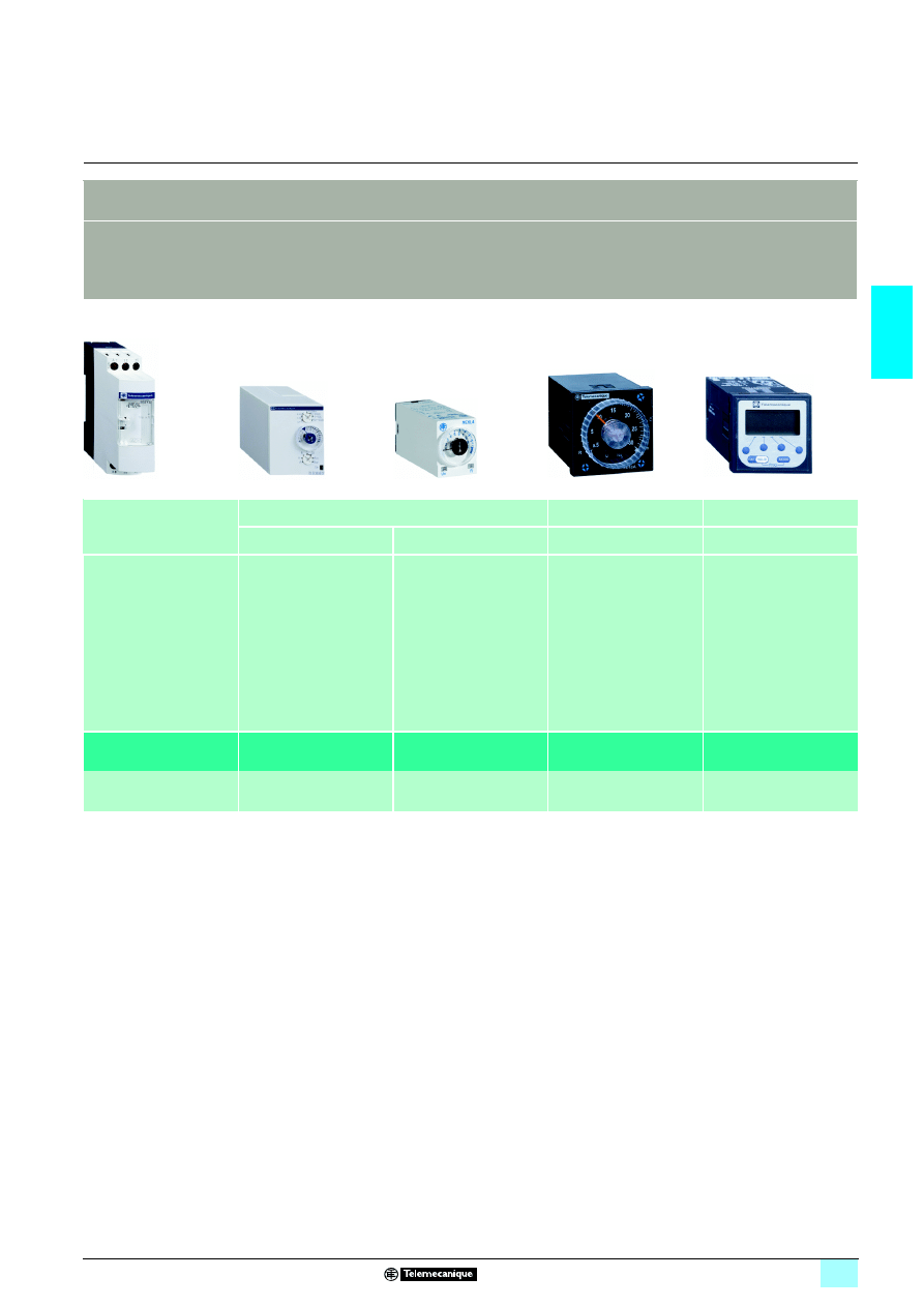
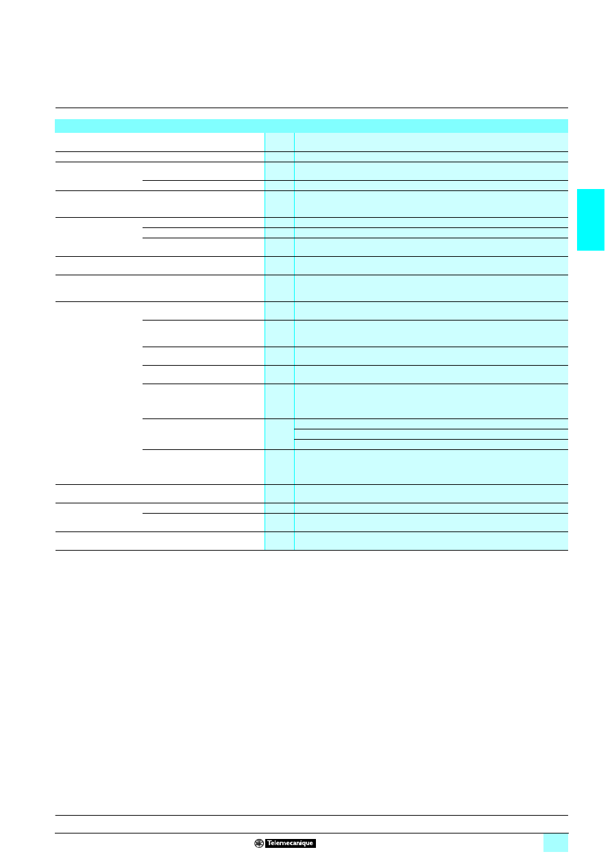
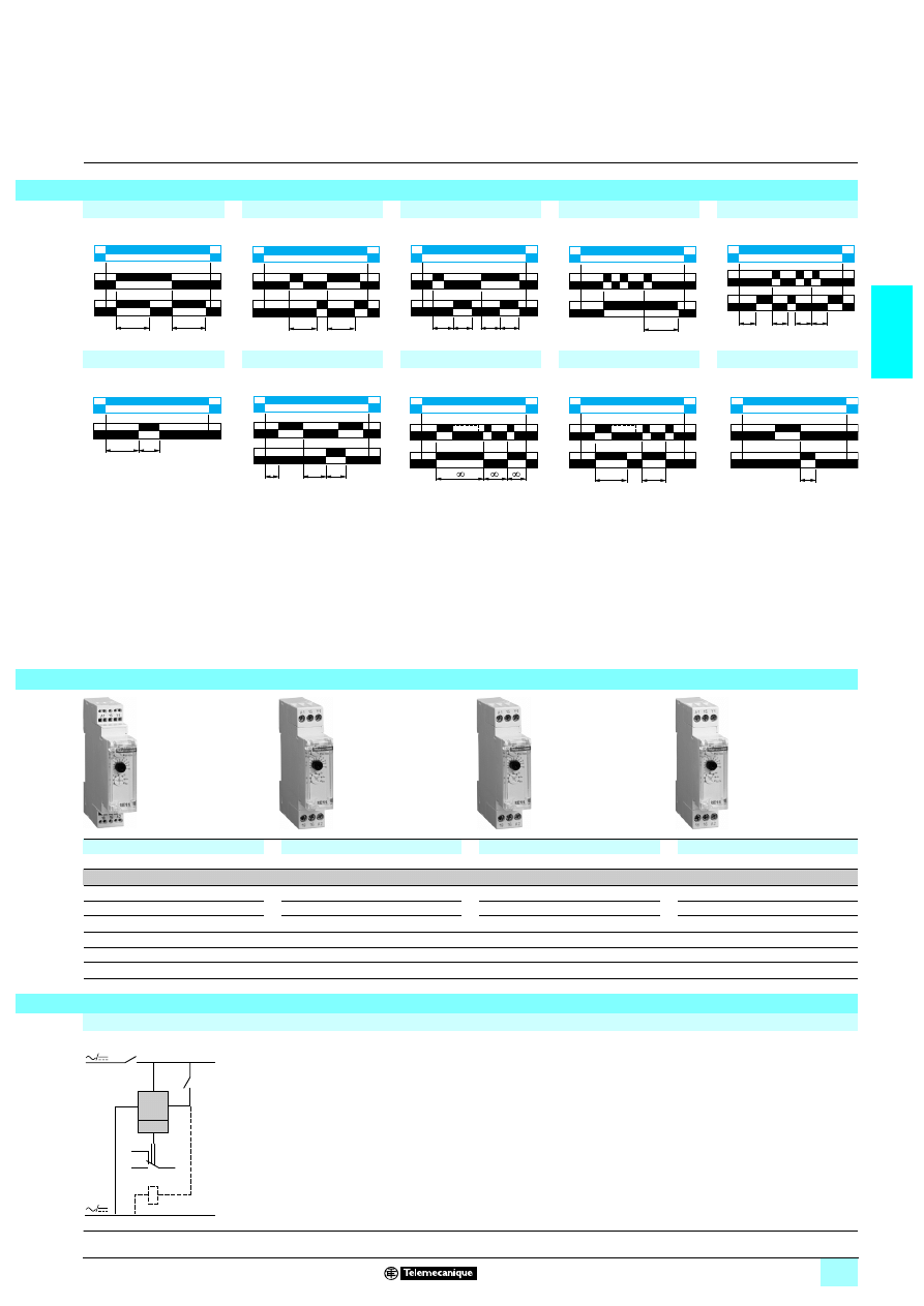
These timing relays enable simple automation cycles to be set up using wired logic.
They can also be used to complement the functions of PLCs.
Relay
Relay outputs provide complete isolation between the supply and output circuits.
It is possible to have several output circuits.
Optimum
Plug-in
Panel-mounted
Universal
Miniature
Analogue
Digital
1 range,
depending on model :
0.5 s, 3 s, 10 s, 30 s, 300 s,
30 min
7 ranges :
1 s, 10 s, 1 min, 10 min, 1 h,
10 h, 100 h
7 ranges :
0,1 s...1 s
1 s...10 s
0,1 min...1 min
1 min...10 min
0,1 h...1 h
1 h...10 h
10 h...100 h
14 ranges :
1,2 s, 3 s, 12 s, 30 s, 120 s,
300 s, 12 min, 30 min,
120 min, 300 min, 12 h, 30 h,
120 h, 300 h
Depending on model :
7 ranges :
99.99 s, 999.99 s, 99 min 59 s,
99.99 min, 999.9 min,
99 h 59 min, 999.9 h
11 ranges :
99.99 s, 999.99 s, 9999 s,
99 min 59 s, 99.99 min,
999.9 min, 9999 min,
99 h 59 min, 99,99 h,
999.9 h, 9999 h
RE8
RE 88 867
111
RE XL
1TM11
RE 48A
111
RE 88 857
111
2/44 to 2/47
2/48 to 2/55
2/56 and 2/57
2/58 to 2/65
2/66 to 2/71
2/4
2
Presentation
2
Zelio Time - timing relays
2
Presentation
A timing relay is a component which is designed for timing events in industrial
automation systems by closing or opening contacts before, during or after a set
timing period.
There are two main 'families' of timing relays:
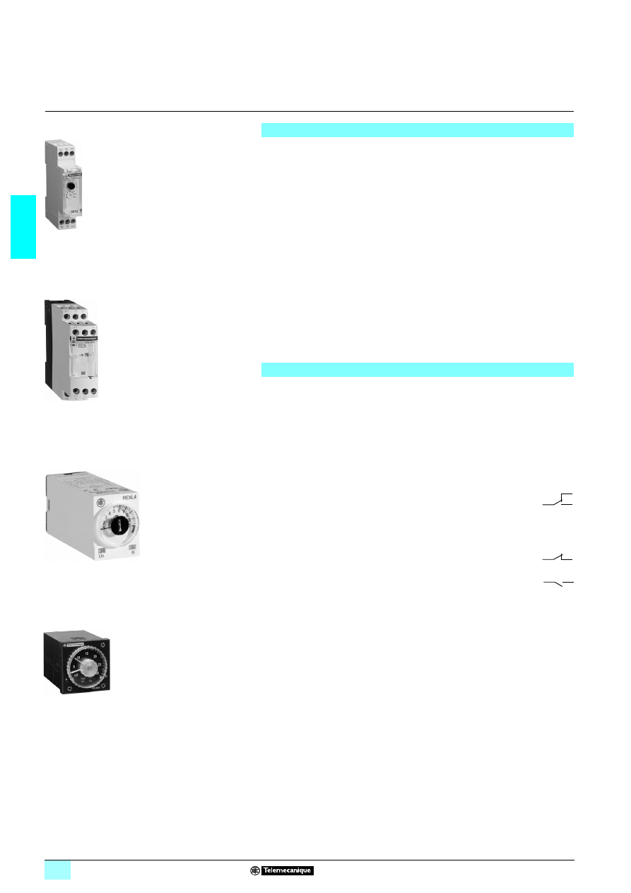
1 “DIN rail mounted” relays (RE7, RE8, RE9, RE11, RE XL…) designed for
mounting on DIN rails in an enclosure,
1 “Panel mounted” relays type RE 48A, designed for mounting on the front of a panel
to give users easy access to the settings.
These relays have one, two or four outputs. Sometimes the second output can be
either timed or instantaneous.
If the power is switched off during the timing period, the relay reverts to its initial
position.
Application examples:
1 opening of automatic doors,
1 alarm,
1 lighting in toilets,
1 car park barriers ...
Definitions
The following definitions will assist in understanding the operation of these relays:
1 Relay output:
This is the most common type of output. When the relay is energised, the moving
armature is attracted by the coil and so actuates the contacts, which change state.
When the relay is de-energised, both the armature and the contacts revert to their
initial position.
This type of output allows complete isolation between the supply and the output.
There are three types of output:
23C/O: changeover contact, i.e. when the relay is de-energised, the
circuit between the common point C and N/C is closed and when the
relay is operating (coil energised), it closes the circuit between the
common point C and N/O.
23N/C: a contact that is closed without being actuated is called a
Normally Closed (N/C) contact.
23N/O: a contact that closes when actuated is called a Normally Open
(N/O) contact.
1 Solid state output:
These outputs are entirely electronic and involve no moving parts; service life is
therefore increased.
1 Breaking capacity:
The current value that a contact is capable of breaking in specified conditions.
1 Mechanical durability:
The number of mechanical operating cycles of the contact or contacts.
1 Minimum switching capacity (or minimum breaking capacity): corresponds to
the minimum required current which can flow through the contacts of a relay.
1 G (Gate) input : Gate input allows timing in progress to be interrupted without
resetting it.
RE11
52
19
31
-1
2
-M
RE7 RL13BU
56
09
04
RE 48A
52
19
38
-4
4-
M
RE XL
53
25
35
C
NO
NC
NC
NO
2/5
2
Presentation
(continued)
2
Zelio Time - timing relays
2
Definitions
(continued)
Functions
Timing functions are identified by letters.
Main timing
functions
Complementary
functions (1)
Definitions
A (2)
Delay on energisation
Ac
Timing after closing and opening of control contact
Ad
Timing on closing of control contact
Ah
Flashing single cycle by operation of control contact
Ak
Asymmetrical On-delay and Off-delay with external
control
At
Delay on energisation with memory
Aw
Off-delay on energisation or on opening of control
contact
B (2)
Timing on impulse, one shot
Bw
Pulse output (width adjustable)
C (2)
Timing after opening of control contact
D (2)
Symmetrical flashing, start with output in rest position
Di (2)
Symmetrical flashing, start with output in operating
position
H (2)
Timing on energisation
He
Pulse-on de-energisation
Ht
Timing on energisation with memory
K
Delay on de-energisation (without auxiliary supply)
L (2)
Asymmetrical flashing, start with output in rest position
Li (2)
Asymmetrical flashing, start with output in operating
position
Lt
Asymmetrical flashing with partial stop of timing
N
Safe-guard
O
Delayed safe-guard
P
Delayed fixed-length pulse
Pt
Impulse counter (on-delay)
Qc
Star-delta timing
Qe
Star-delta timing
Qg
Star-delta timing
Qt
Star-delta timing
T
Bistable relay
Tt
Timed impulse relay
W
On-delay after opening of control contact
(1) Complementary functions enhance the main timing functions.
Example: Ac: timing after closing and opening of control contact.
(2) The most commonly used timing functions.
2/6
2
Selection
2
Zelio Time - timing relays
2
Selection table
Selection criteria
1 Functions (On-delay or Off-delay, counter, flashing…)
1 Supply voltage (example: 4/5 12 V…240 V).
1 Timing range (example: 0.05 s…100 h)
1 Type of output (contact or solid state) and required Number of contacts.
1 Breaking capacity or Rated current of contacts, expressed in Amperes.
This is the maximum current which may flow through the contacts.
Functions
Supply voltage
Timing range
Type of output
Rated
current
Relay
Page
A
1 12 V
0.1 s…100 h
2 C/O contacts
5 A
RE XL2TMJD
2/57
0.1 s …100 h
4 C/O contacts
3 A
RE XL4TMJD
2/57
1 24 V
0.1 s…100 h
2 C/O contacts
5 A
RE XL2TMBD
2/57
0.1 s…100 h
4 C/O contacts
3 A
RE XL4TMBD
2/57
2 24 V
0.1 s…100 h
2 C/O contacts
5 A
RE XL2TMB7
2/57
0.1 s…100 h
4 C/O contacts
3 A
RE XL4TMB7
2/57
2 120 V
0.1 s…100 h
2 C/O contacts
5 A
RE XL2TMF7
2/57
0.1 s…100 h
4 C/O contacts
3 A
RE XL4TMF7
2/57
2 230 V
0.1 s…100 h
2 C/O contacts
5 A
RE XL2TMP7
2/57
0.1 s…100 h
4 C/O contacts
3 A
RE XL4TMP7
2/57
2/1 24…240 V
0.1 s…10 s
1 solid state output
0.7 A
RE9 TA11MW
2/20
0.3 s…30 s
0.7 A
RE9 TA31MW
2/20
3 s…300 s
0.7 A
RE9 TA21MW
2/20
40 s…60 min
0.7 A
RE9 TA51MW
2/20
1 s…100 h
0.7 A
RE11 LA MW
2/16
0.02 s…300 h
2 timed C/O contacts 5 A
RE 48A TM12 MW
2/58
2/1 24 V, 2 110…240 V 0.05 s…300 h
1 C/O contact
8 A
RE7 TL11BU
2/36
0.1 s…3 s
8 A
RE8 TA61BUTQ
2/44
0.1s…10 s
8 A
RE8 TA11BUTQ
2/44
0.3 s…30 s
8 A
RE8 TA31BUTQ
2/44
3 s…300 s
8 A
RE8 TA21BUTQ
2/44
20…30 min
8 A
RE8 TA41BUTQ
2/44
2/1 24 V, 2 110…240 V,
2/1 42…48 V
0.05 s…300 h
2 C/O contacts
8 A
RE7 TP13BU
2/38
A, Ac, At, B, Bw, C, D, Di, H, Ht
2 24…240 V
1 s…100 h
1 solid state output
0.7 A
RE11 LM BM
2/17
2/1 12 V
1 s…100 h
1 C/O contact
8 A
RE11 RM JU
2/27
2/1 12…240 V
1 s…100 h
1 C/O contact
8 A
RE11 RM MW
2/26
1 s…100 h
8 A
RE11 RM MWS
2/27
1 24 V, 2 24…240 V
1 s…100 h
1 C/O contact
8 A
RE11 RM MU
2/26
A, At
1 24 V, 2 24…240 V
1 s…100 h
1 C/O contact
8 A
RE11 RA MU
2/24
A, At, Aw
2 110…240 V, 2/1 24 V,
2/1 42…48 V
0.05 s…300 h
1 C/O contact
8 A
RE7 TM11BU
2/36
A, At, B, C, D, Di, H, Ht
1 24 V, 2 24…240 V
1 s…10 h
1 C/O contact
5 A
RE11 RME MU
2/27
A, B, C, Di
2/1 24…240 V
0.02 s…300 h
2 timed C/O contacts 5 A
RE 48A ML12 MW
2/63
A, C, D, Di, H, Qg, Qt, W
2 110…240 V, 2/1 24 V,
2/1 42…48 V
0.05 s…300 h
2 C/O contacts
8 A
RE7 MY13BU
2/39
2/1 24…240 V
0.05 s…300 h
2 C/O contacts
8 A
RE7 MY13MW
2/39
A, C, D, Di, H, W
2 110…240 V, 2/1 24 V,
2/1 42…48 V
0.05 s…300 h
1 C/O contact
8 A
RE7 ML11BU
2/36
A, D, Di, H
2/1 24…240 V
2 24…240 V
0.1 s…10 s et
3 s…300 s
1 solid state output
0.7 A
RE9 MS21MW
2/20
A1, A2, H1, H2
2/1 24…240 V
0.02 s…300 h
2 C/O contacts
5 A
RE 48A MH13 MW
2/63
Ac
2 110…240 V, 2/1 24 V,
2/1 42…48 V
0.05 s…300 h
1 C/O contact
8 A
RE7 MA11BU
2/36
0.05 s…300 h
2 C/O contacts
8 A
RE7 MA13BU
2/38
Ad, Ah, N, O, P, Pt, TI, Tt, W
1 24 V, 2 24…240 V
1 s…100 h
1 C/O contact
8 A
RE11 RMX MU
2/27
Ak
2 110…240 V, 2/1 24 V,
2/1 42…48 V
0.05 s…300 h
1 C/O contact
8 A
RE7 MV11BU
2/36
2/7
2
Selection
(continued)
2
Zelio Time - timing relays
2
Selection table
(continued)
Functions
Supply voltage
Timing range
Type of output
Rated
current
Relay
Page
B
1 24 V, 2 24…240 V
1 s…100 h
1 C/O contact
8 A
RE11 RB MU
2/25
C
2/1 24 V
0.1 s…10 s
1 C/O contact
8 A
RE8 RA11BTQ
2/44
0.3 s…30 s
8 A
RE8 RA31BTQ
2/44
3 s…300 s
8 A
RE8 RA21BTQ
2/44
1 24 V, 2 24…240 V
1 s…100 h
1 C/O contact
8 A
RE11 RC MU
2/25
2 110…240 V
0.1 s…10 s
1 C/O contact
8 A
RE8 RA11FUTQ
2/44
0.3 s…30 s
8 A
RE8 RA31FUTQ
2/44
3 s…300 s
8 A
RE8 RA21FUTQ
2/44
20 s…30 min
8 A
RE8 RA41FUTQ
2/44
2/1 24 V, 2 110…240 V,
2/1 42…48 V
0.05 s…300 h
1 C/O contact
8 A
RE7 RA11BU
2/37
0.05 s…300 h
8 A
RE7 RM11BU
2/37
0.05 s…300 h
2 C/O contacts
8 A
RE7 RL13BU
2/38
2 24…240 V
0.1 s…10 s
1 solid state output
0.7 A
RE9 RA11MW7
2/20
0.3 s…30 s
0.7 A
RE9 RA31MW7
2/20
3 s…300 s
0.7 A
RE9 RA21MW7
2/20
40 s…60 min
0.7 A
RE9 RA51MW7
2/20
1 s…100 h
0.7 A
RE11 LC BM
2/17
D
2/1 24 V, 2 110…240 V 0.05 s…300 h
1 C/O contact
8 A
RE7 CL11BU
2/37
0.1 s…10 s
8 A
RE8 CL11BUTQ
2/45
2/1 24 V, 2 110…240 V,
2/1 42…48 V
0.05 s…300 h
2 C/O contacts
8 A
RE7 CP13BU
2/39
H
2/1 24 V, 2 110…240 V 0.05 s…300 h
1 C/O contact
8 A
RE7 PE11BU
2/37
0.1 s…10 s
8 A
RE8 PE11BUTQ
2/46
0.3 s…30 s
8 A
RE8 PE31BUTQ
2/46
3 s…300 s
8 A
RE8 PE21BUTQ
2/46
2/1 24 V, 2 110…240 V,
2/1 42…48 V
0.05 s…300 h
2 C/O contacts
8 A
RE7 PP13BU
2/39
2 24…240 V
1 s…100 h
1 solid state output
0.7 A
RE11 LH BM
2/16
H, Ht
1 24 V, 2 24…240 V
1 s…100 h
1 C/O contact
8 A
RE11 RH MU
2/24
He
2/1 24 V, 2 110…240 V 0.05 s…0.5 s
1 C/O contact
8 A
RE8 PT01BUTQ
2/47
K
2/1 24…240 V
0.05 s…10 min
1 C/O contact
5 A
RE7 RB11MW
2/37
2/1 24 V, 2 110…240 V 0.05 s…0.5 s
1 C/O contact
8 A
RE8 RB51BUTQ
2/45
0.1 s…10 s
8 A
RE8 RB11BUTQ
2/45
0.3 s…30 s
8 A
RE8 RB31BUTQ
2/45
2/1 24…240 V
0.05 s…10 min
2 C/O contacts
5 A
RE7 RB13MW
2/38
L, Li
1 24 V, 2 24…240 V
1 s…100 h
1 C/O contact
8 A
RE11 RL MU
2/25
2 24…240 V
1 s…100 h
1 solid state output
0.7 A
RE11 LL BM
2/17
2/1 12 V
1 s…100 h
1 C/O contact
8 A
RE11 RL JU
2/25
2/1 24…240 V
0.02 s…300 h
2 timed C/O contacts 5 A
RE 48A CV12 MW
2/63
L, Li, Lt
2 110…240 V, 2/1 24 V,
2/1 42…48 V
0.05 s…300 h
1 C/O contact
8 A
RE7 CV11BU
2/37
Qc
2/1 24 V, 2 110…240 V 0.1 s…10 s
1 C/O contact
8 A
RE8 YG11BUTQ
2/47
0.3 s…30 s
8 A
RE8 YG31BUTQ
2/47
3 s…300 s
8 A
RE8 YG21BUTQ
2/47
Qe
2/1 24 V
0.3 s…30 s
1 NO + 1 NC
8 A
RE8 YA32BTQ
2/47
2 110…240 V
0.3 s…30 s
1 NO + 1 NC
8 A
RE8 YA32FUTQ
2/47
2 380…415 V
0.3 s…30 s
1 NO + 1 NC
8 A
RE8 YA32QTQ
2/47
Qg
2/1 24 V, 2 110…240 V,
2/1 42…48 V
0.05 s…300 h
1 NO + 1 NC
8 A
RE7 YR12BU
2/39
Qt
2/1 24 V, 2 110…240 V,
2/1 42…48 V
0.05 s…300 h
2 C/O contacts
8 A
RE7 YA12BU
2/39
W
2/1 24 V
0.1 s…10 s
1 C/O contact
8 A
RE8 PD11BTQ
2/46
0.3 s…30 s
8 A
RE8 PD31BTQ
2/46
3 s…300 s
8 A
RE8 PD21BTQ
2/46
2 110…240 V
0.1 s…10 s
1 C/O contact
8 A
RE8 PD11FUTQ
2/46
0.3 s…30 s
8 A
RE8 PD31FUTQ
2/46
3 s…300 s
8 A
RE8 PD21FUTQ
2/46
2/1 24 V, 2 110…240 V,
2/1 42…48 V
0.05 s…300 h
2 C/O contacts
8 A
RE7 PD13BU
2/39
W, Ht
2/1 24 V, 2 110…240 V,
2/1 42…48 V
0.05 s…300 h
1 C/O contact
8 A
RE7 PM11BU
2/37
2/8
2
Functions
2
Zelio Time - timing relays
2
Functions
U : Supply
R : Relay or solid state output
R1/R2 : 2 timed outputs
R2 inst. :The second output is instantaneous if the right
position is selected
T : Timing period
C : Control contact
G : Gate
Ta : Adjustable On-delay
Tr : Adjustable Off-delay
Function diagram:
Relay de-energised
Relay energised
Output open
Output closed
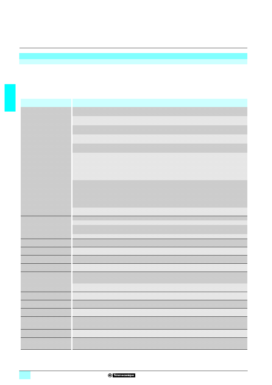
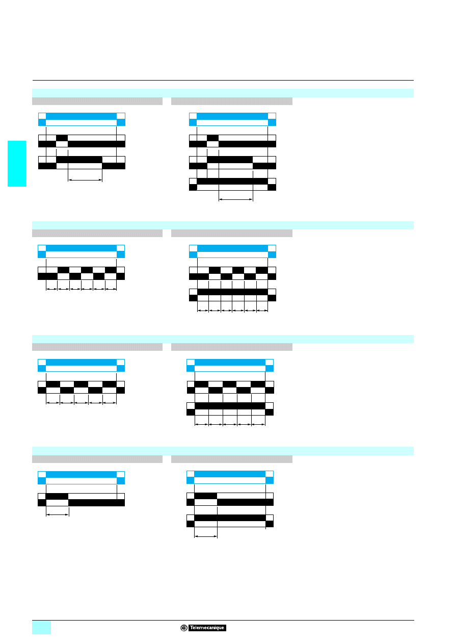
Function A : Delay on energisation
1 output
2 outputs
The timing period T begins on
energisation.
After timing, the output(s) R close(s).
The second output can be either timed
or instantaneous.
2 timed outputs (R1/R2) or 1 timed output
(R1) and 1 instantaneous output (R2 inst.).
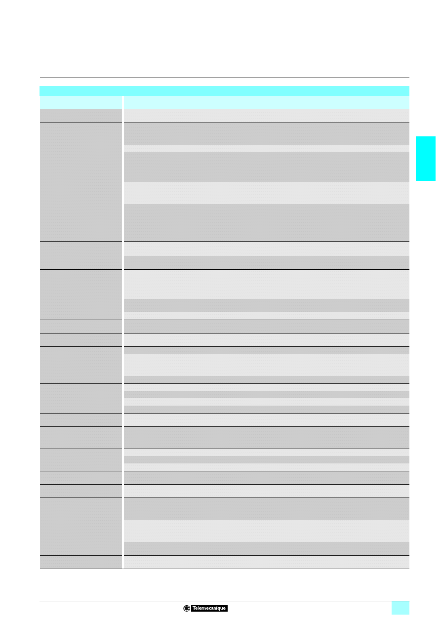
Function Ac: Timing after closing and opening of control contact
1 output
2 outputs
After power-up, closing of the control
contact C causes the timing period T to
start (timing can be interrupted by
operating the Gate control contact G).
At the end of this timing period, the relay
closes.
When control contact C re-opens, the
timing T starts.
At the end of this timing period T, the
output reverts to its initial position (timing
can be interrupted by operating the Gate
control contact G).
The second output can be either timed
or instantaneous.
T = t1 + t2 + …
T = t’1 + t’2 + …
2 timed outputs (R1/R2) or 1 timed output
(R1) and 1 instantaneous output (R2 inst.).
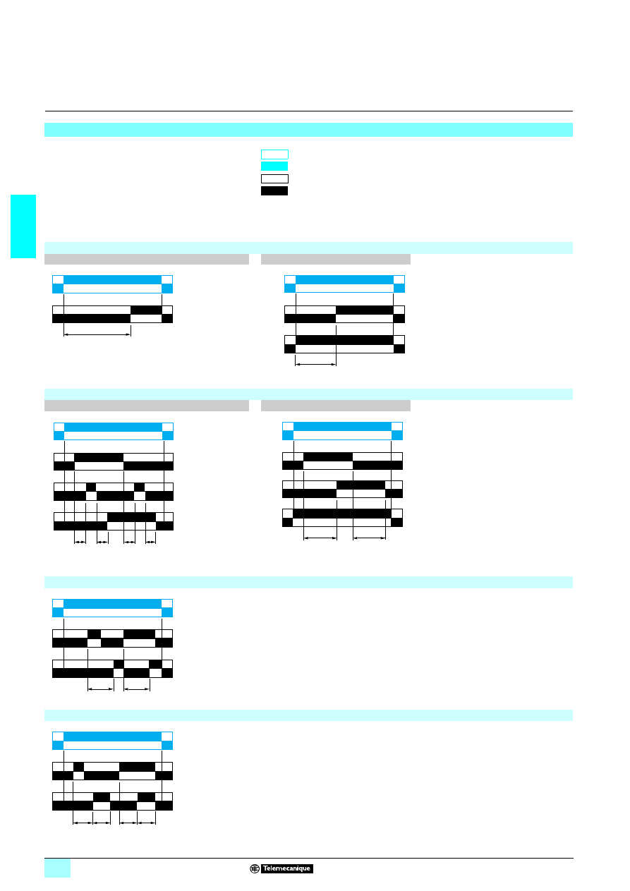
Function Ad: Timing on closing of control contact.
After power-up, pulsing or maintaining of control contact C starts the timing T.
At the end of this timing period T, the output R closes.
The output R will be reset the next time control contact C is pulsed or maintained.
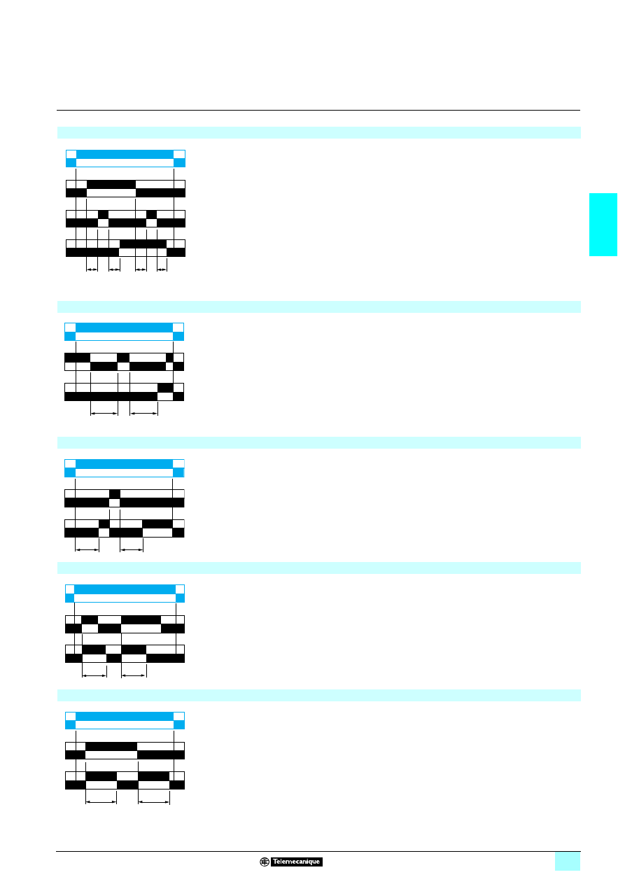
Function Ah: Flashing single cycle by operation of control contact
After power-up, pulsing or maintaining of control contact C starts the timing T.
A single cycle then starts with 2 timing periods T of equal duration (start with output
in rest position)
Output R closes at the end of the first timing period T and reverts to its initial position
at the end of the second timing period T.
Control contact C must be reset in order to re-start the single flashing cycle.
U
R
T
U
R1/R2
T
R2 inst.
U
C
t1
G
R
t'1
t2
t'2
U
C
R1/R2
T
T
R2 inst.
U
R
C
T
T
U
R
C
T
T
T
T
2/9
2
Functions
(continued)
2
Zelio Time - timing relays
2
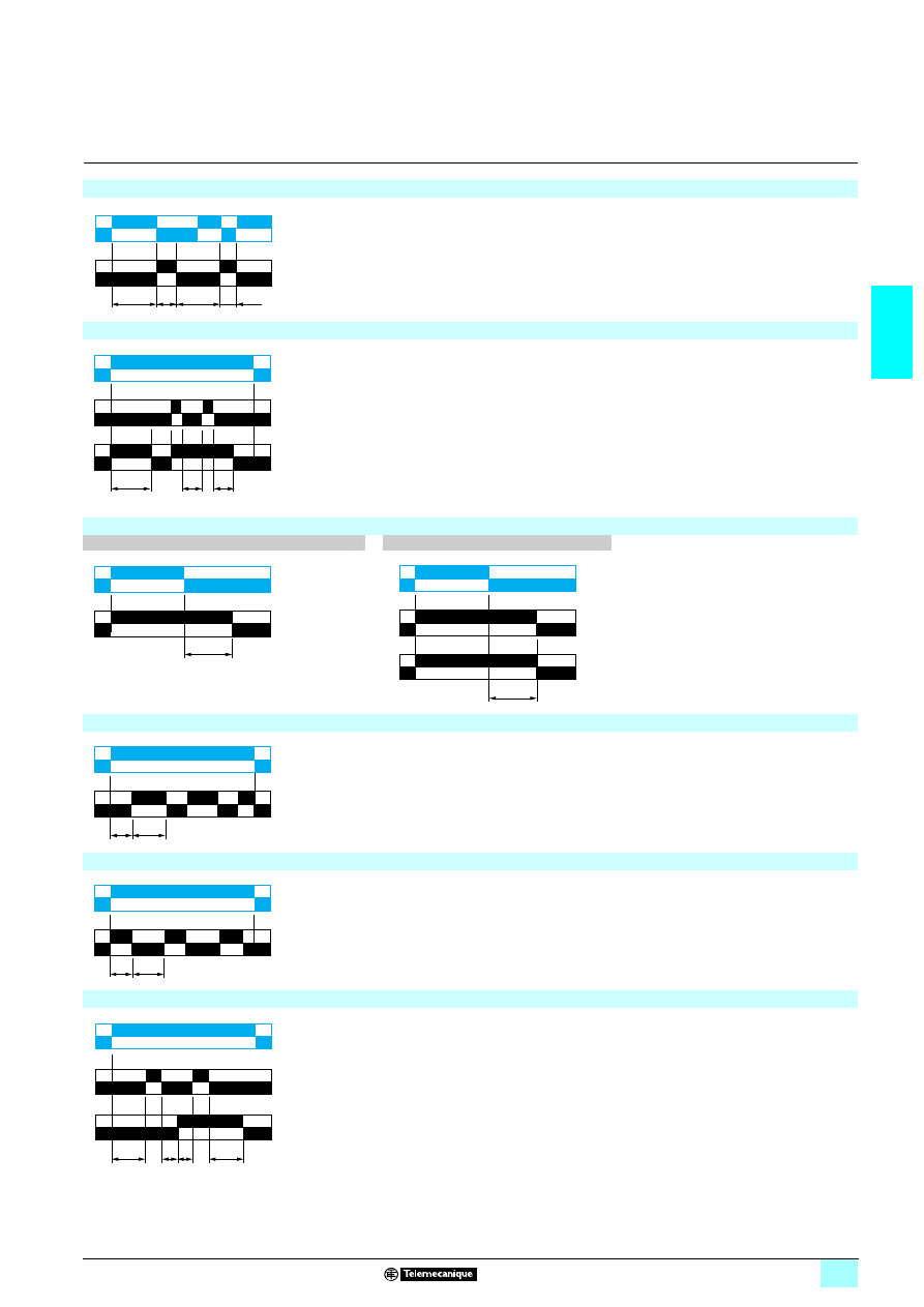
Function Ak: Asymmetrical On-delay and Off-delay with external control
After power-up and closing of the control contact C, timing starts for a period Ta
(timing can be interrupted by operating the Gate control contact G).
At the end of this timing period Ta, the output R closes.
Opening of control contact C causes a second timing period Tr to start (timing can
be interrupted by operating the Gate control contact G).
At the end of this timing period Tr, the output R reverts to its initial state.
Ta = t1 + t2 + …
Tr = t’1 + t’2 + …
Function At: Delay on energisation with memory
After power-up, the first opening of control contact C starts the timing. Timing can be
interrupted each time control contact C closes. When the cumulative total of time
periods elapsed reaches the pre-set value T, the output relay closes.
T = t1 + t2 + …
Function Aw: Off-delay on energisation or on opening of control contact
The timing period T starts on energisation.
At the end of the timing period T, the output R closes.
Closing of the control contact C makes the output R open.
Opening of control contact C restarts timing period T.
At the end of timing period T, the output R closes.
Function B: Timing on impulse, one shot
After power-up, pulsing or maintaining control contact C starts the timing T.
The output R closes for the duration of the timing period T then reverts to its initial
state.
Function Bw: Pulse output (width adjustable)
On closing and opening of control contact C, the output R closes for the duration of
the timing period T.
U
C
t1
G
R
t'1
t2
t'2
U
R
C
t1
t2
U
R
C
T
T
U
R
C
T
T
U
R
C
T
T
2/10
2
Functions
(continued)
2
Zelio Time - timing relays
2
Function C: Timing after opening of control contact
1 output
2 outputs
After power-up and closing of the control
contact C, the output R closes.
When control contact C re-opens,
timing T starts.
At the end of the timing period, the
output(s) R revert(s) to its/their initial
state.
The second output can be either timed or
instantaneous.
2 timed outputs (R1/R2) or 1 timed output (R1)
and 1 instantaneous output (R2 inst.).
Function D: Symmetrical flashing, start with output in rest position
1 output
2 outputs
Repetitive cycle with two timing periods T
of equal duration, with output(s) R
changing state at the end of each timing
period T.
The second output can be either timed or
instantaneous.
2 timed outputs (R1/R2) or 1 timed output (R1)
and 1 instantaneous output (R2 inst.).
Function Di: Symmetrical flashing, start with output in operating position
1 output
2 outputs
Repetitive cycle with two timing periods T
of equal duration, with output(s) R
changing state at the end of each timing
period T.
The second output can be either timed or
instantaneous.
2 timed outputs (R1/R2) or 1 timed output (R1)
and 1 instantaneous output (R2 inst.).
Function H: Timing on energisation
1 output
2 outputs
On energisation of the relay, timing
period T starts and the output(s) R
close(s).
At the end of the timing period T, the
output(s) R revert(s) to its/their initial
state.
The second output can be either timed or
instantaneous.
2 timed outputs (R1/R2) or 1 timed output (R1)
and 1 instantaneous output (R2 inst.).
U
C
R
T
U
R1/R2
C
T
R2 inst.
T
T
T
T
T
T
U
R
U
R1/R2
T
T
T
T
T
T
R2 inst.
T
T
T
T
T
U
R
U
R1/R2
T
T
T
T
T
R2 inst.
U
R
T
U
R1/R2
T
R2 inst.
2/11
2
Functions
(continued)
2
Zelio Time - timing relays
2
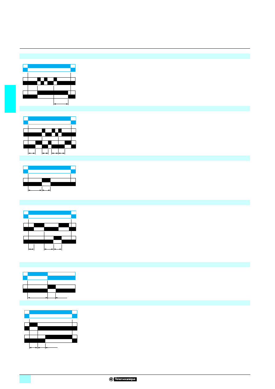
Function He: Pulse-on de-energisation
On de-energisation, the output R closes for the duration of a timing period T.
Function Ht: Timing on energisation with memory
On energisation, the output R closes for the duration of a timing period T then reverts
to its initial state.
Pulsing or maintaining control contact C will again close the output R.
Timing T is only active when control contact C is released and so the output R will
not revert to its initial state until after a time t1 + t2 + … .
The relay memorises the total, cumulative opening time of control contact C and,
once the set time T is reached, the output R reverts to its initial state.
T = t1 + t2 + …
Function K: Delay on de-energisation (without auxiliary supply)
1 output
2 outputs
On energisation, the output(s) R close(s).
On de-energisation, timing period T starts
and, at the end of this period, the
output(s) R revert(s) to its/their initial
state.
Function L: Asymmetrical flashing, start with output in rest position
Repetitive cycle comprises of two, independently adjustable timing periods Ta and
Tr. Each timing period corresponds to a different state of the output R.
Function Li: Asymmetrical flashing, start with output in operating position
Repetitive cycle comprises of two, independently adjustable timing periods Ta and
Tr. Each timing period corresponds to a different state of the output R.
Function Lt: Asymmetrical flashing with partial stop of timing
Repetitive cycle comprises of two, independently adjustable timing periods Ta and
Tr. Each timing period corresponds to a different state of the output R.
Gate control contact G can be operated to partially stop timing periods Ta and Tr.
Tr = t1 + t2 + …
Ta = t’1 + t’2 + …
U
R
> 80 ms
80 ms
T
< T
U
R
C
t1
t2
T
U
R
T
U
R1
R2
T
Tr
Ta
U
R
Ta
Tr
U
R
R
G
t1
t'2
t2 t'1
U
2/12
2
Functions
(continued)
2
Zelio Time - timing relays
2
Function N: Safe-guard
After power-up and an initial control pulse C, the output R closes.
If the interval between two control pulses C is greater than the set timing period T,
timing elapses normally and the output R closes at the end of the timing period. If the
interval is not greater than the set timing period, the output R remains closed until
this condition is met.
Function O: Delayed safe-guard
An initial timing period T begins on energisation. At the end of this timing period, the
output R closes.
As soon as there is a control pulse C, the output R reverts to its initial state and
remains in that state until the interval between two control pulses is less than the
value of the set timing period T. Otherwise, the output R closes at the end of the
timing period T.
Function P: Delayed fixed-length pulse
The timing period T begins on energisation.
At the end of this period, the output R closes for a fixed time P.
Function Pt: Impulse counter (on-delay)
On energisation, timing period T starts (it can be interrupted by operating the Gate
control contact G).
At the end of this period, the output R closes for a fixed time P.
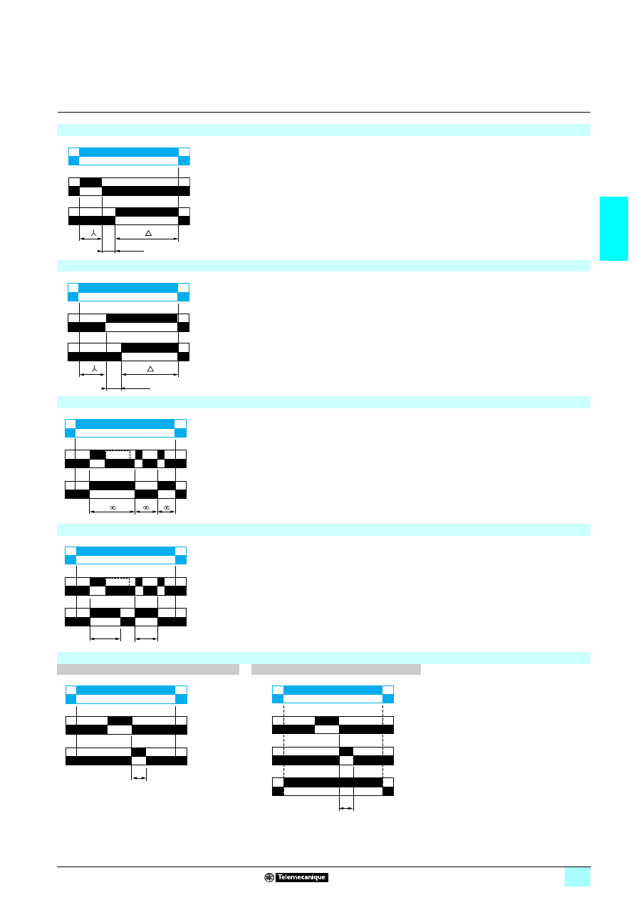
Function Qc: Star-delta timing
On energisation, the star contact closes instantaneously and timing starts.
At the end of the timing period, the star contact opens.
After a 50 ms pause, the delta contact closes and remains in this position.
Function Qe: Star-delta timing
Timing for star-delta starter with contact for switching to star connection.
T
U
C
R
T
T
T
U
C
R
t<T
U
R
T
P
P = 500 ms
t1
t2
P
U
G
R
T = t1 + t2 + …
P = 500 ms
T
50 ms
U
R
T
80 ms
U
R1
R2
2/13
2
Functions
(continued)
2
Zelio Time - timing relays
2
Function Qg: Star-delta timing
Timing for star-delta starter with contact for switching to star connection.
Function Qt: Star-delta timing
Timing for star-delta starter with double On-delay period.
Function T: Bistable relay
After power-up, pulsing or maintaining of control contact C switches the output on.
A second pulse on the control contact C switches the output R off.
Function Tt: Timed impulse relay
After power-up, pulsing or maintaining of control contact C switches output R on and
starts timing T.
The output switches off at the end of the timing period T or following a second pulse
on the control contact C.
Function W: On-delay after opening of control contact
1 output
2 outputs
After power-up and opening of the control
contact, the output(s) close(s) for a timing
period T.
At the end of this timing period the
output(s) revert(s) to its/their initial state.
The second output can be either timed or
instantaneous.
2 timed outputs (R1/R2) or 1 timed output (R1)
and 1 instantaneous output (R2 inst.).
T
T
50 ms
U
R1
R2
U
R1
R2
T
T
50 ms
U
C
R
U
C
R
T
t<T
T
U
C
R
U
C
R1/R2
T
R2 inst.
2/14
2
Characteristics
2
Zelio Time -
modular timing relays
2
Relays with solid state output,
width 17.5 mm
Timing characteristics
Selectable timing ranges
by selector switch on front panel
s
0.1…1
1…10
min
0.1…1
1…10
h
0.1…1
1…10
10…100
Repeat accuracy
(with constant parameters)
Conforming to IEC 61812-1
± 0.5 %
Drift
Temperature
± 0.05 % / °C
Voltage
± 0.2 % / V
Setting accuracy
at full scale
Conforming to IEC 61812-1
± 10 % at 25 °C
Minimum duration
of control pulse
Typical
ms
50
Maximum reset time
by de-energisation
Typical
ms
350
Immunity to microbreaks
Typical
ms
> 10
Supply characteristics
Supply voltage
V
Depending on version:
2 24…240
2/1324…240
Frequency
Hz
50/60
Operating range
85…110 % Un
On-load factor
100 %
Maximum
power consumption
Depending
on model
1 24 V
W
0.6
1 240 V
W
1.5
2 240 V
VA
32
Output characteristics
Output type
Solid state
Breaking capacity
A
2/130.7 at 20° C (0.5 A UL)
Derating
mA
5 / °C
Maximum permissible current
A
20
≤ 10 ms
Minimum breaking current
mA
10
Leakage current
mA
< 5
Maximum switching voltage
V
2/13250
Typical voltage drop at terminals
3-wire 4 V - 2-wire 8 V
Electrical life
10
8
operations
Mechanical life
10
8
operations
Dielectric strength
Conforming to
IEC 60664, IEC 60255-5
kV
2.5...1 mA / 1 min
Input characteristics
Input type
Volt-free contact (no potential)
Control possible by 3-wire sensor with PNP output, maximum residual voltage: 0.4 V
whatever the supply voltage of the timer
References :
pages 2/16 and 2/17
Dimensions :
page 2/16
Schemes :
page 2/17
2/15
2
Characteristics
(continued)
2
Zelio Time -
modular timing relays
2
Relays with solid state output,
width 17.5 mm
General characteristics
Conforming to standards
IEC 61812-1, EN 50081-1/2, EN 50082-1/2, LV directives (73/23/EEC + 93/68/EEC
(
4 marking) + EMC directive (89/336/EEC + IEC 60669-2-3)
Approvals
cULus, CSA
Ambient air temperature
around the device
Storage
°C
- 30…+ 60
Operation
°C
- 20…+ 60
Creepage distance
and clearance
Conforming to IEC 60664-1
kV
4 kV/3
Degree of protection
conforming to IEC 60529
Terminal block
IP 20
Housing
IP 40
Front panel
IP 50
Vibration resistance
Conforming to IEC 60068-2-6
f = 10…55 Hz
A = 0.35 mm
Relative humidity
without condensation
Conforming to IEC 60068-2-3
93 %
Electromagnetic
compatibility
Immunity to electrostatic discharge,
conforming to IEC 61000-4-2
Level III (Air 8 kV/Contact 6 kV)
Immunity to electromagnetic fields,
conforming to ENV 50140/204
(IEC 61000-4-3)
Level III (10 V/m: 80 MHz…1 GHz)
Immunity to fast transients in bursts,
conforming to IEC 61000-4-4
Level III (direct 2 kV / capacitive connecting clip 1 kV)
Immunity to surges on the power supply,
conforming to IEC 61000-4-5
Level III (common mode 2 kV / differential mode 1 kV)
Immunity to radio frequency
interference in common mode,
conforming to ENV 50141
(IEC 61000-4-6)
Level III (10 V rms: 0.15…80 MHz)
Immunity to voltage dips and breaks,
conforming to IEC 61000-4-11
30 % / 10 ms
60 % / 100 ms
95 % / 5 s
Radiated and mains conducted
disturbance,
conforming to EN 55022
(EN 55011 Group 1)
Class B
Fixing
Symmetrical mounting rail
(EN 50022)
mm
35
Clamping capacity
Without cable end
mm
2
2 x 2.5 or 1 x 4
With cable end
mm
2
2 x 1.5
Housing material
Self-extinguishing
References :
pages 2/16 and 2/17
Dimensions :
page 2/16
Schemes :
page 2/17
2/16
2
Functions,
references,
dimensions,
schemes
2
Zelio Time -
modular timing relays
2
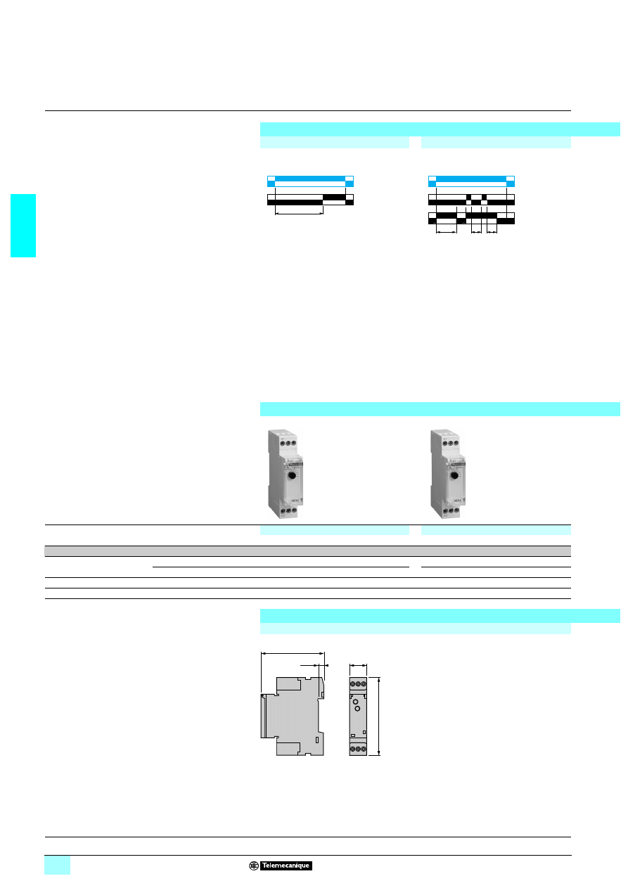
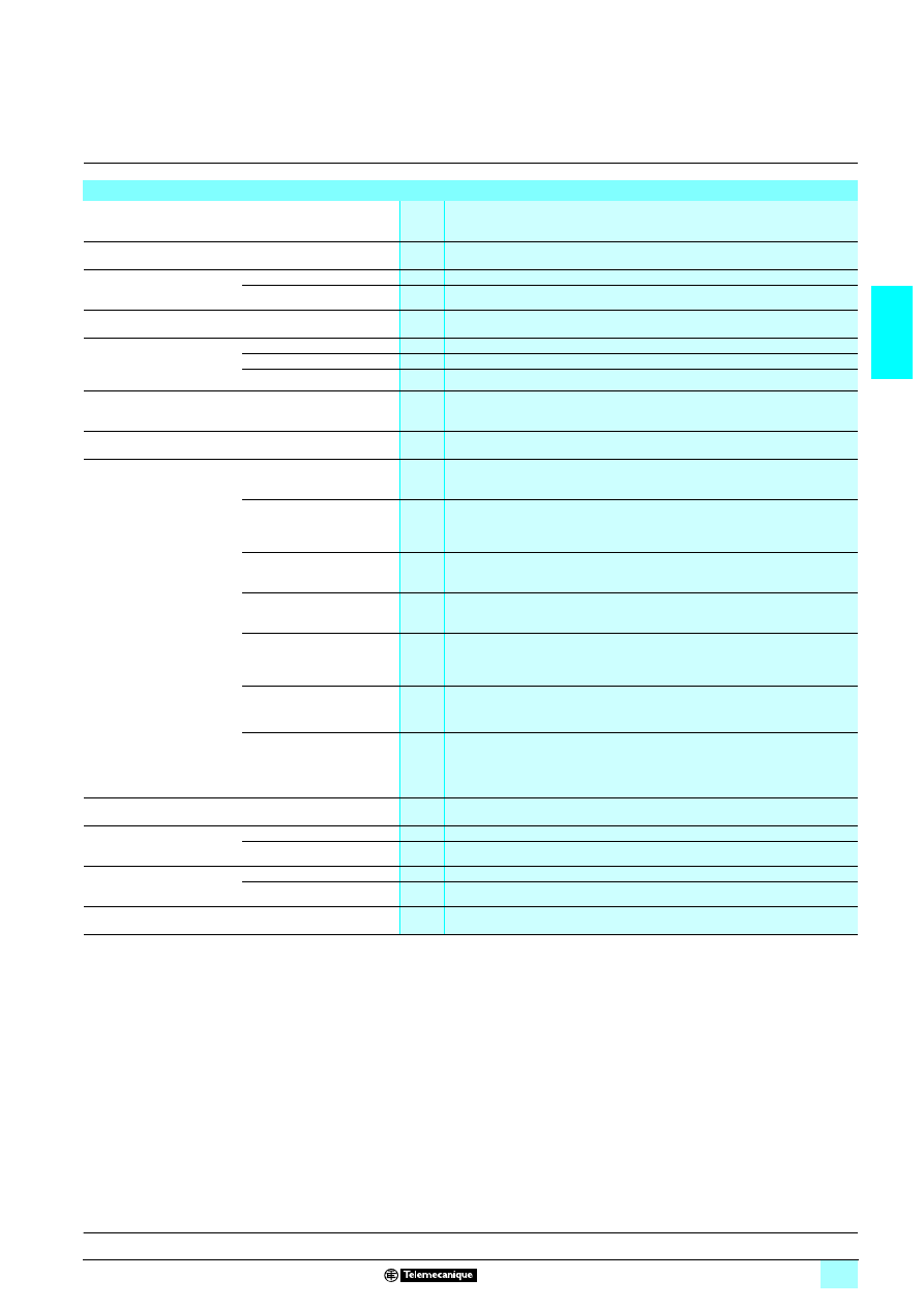
Relays with solid state output,
width 17.5 mm
Solid state output
1 Multifunction, dual function or single function
1 Multi-range (7 selectable ranges)
1 Multivoltage
1 Solid state output: 0.7 A
1 Screw terminals
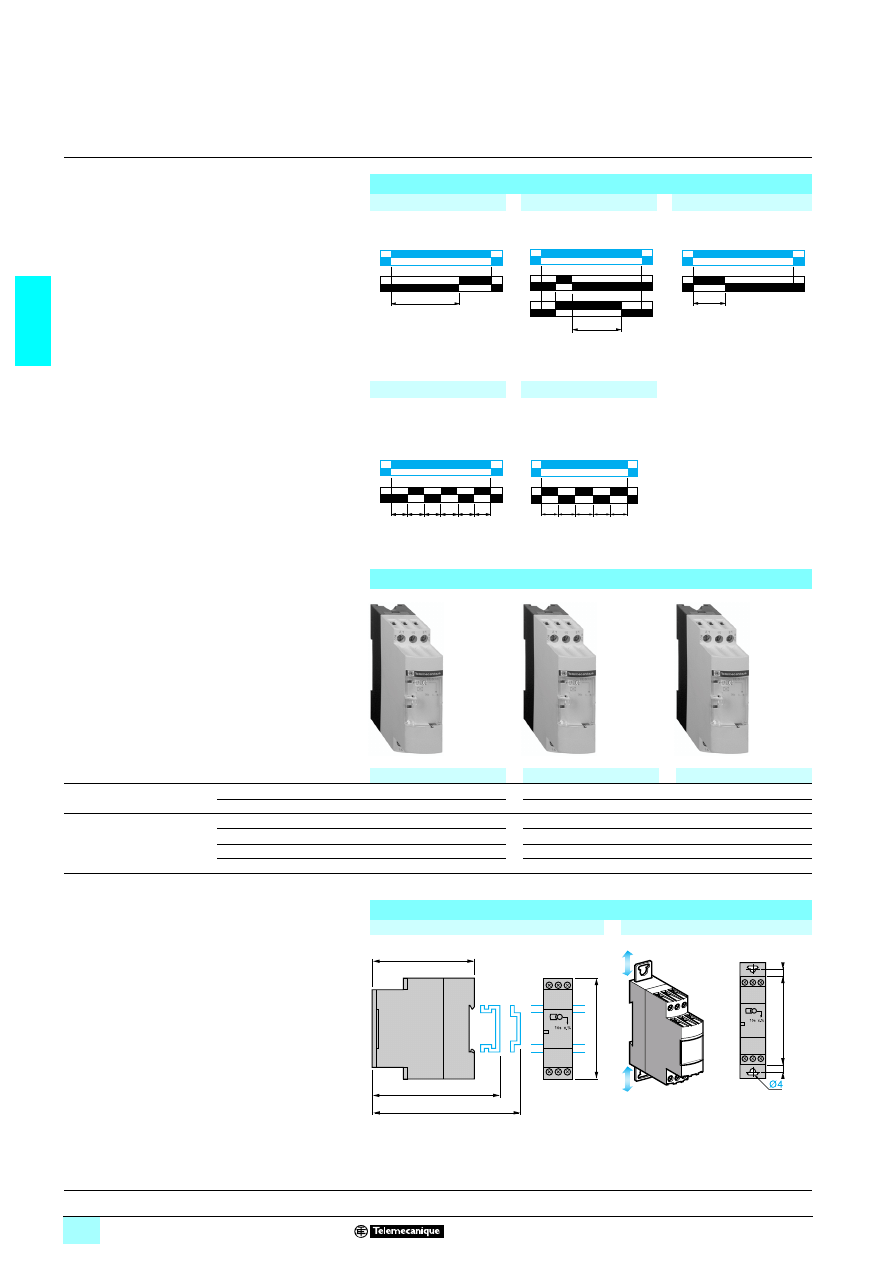
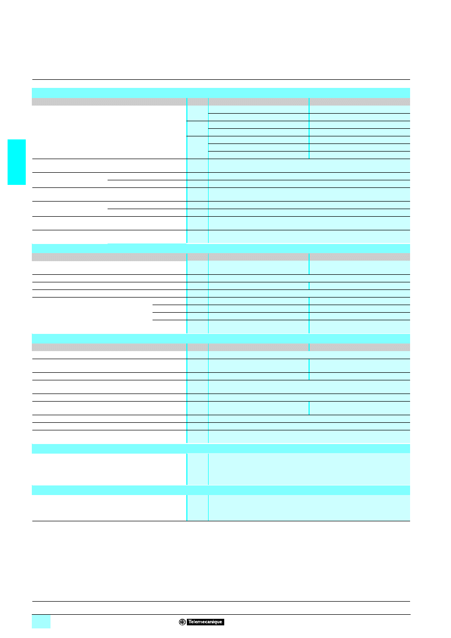
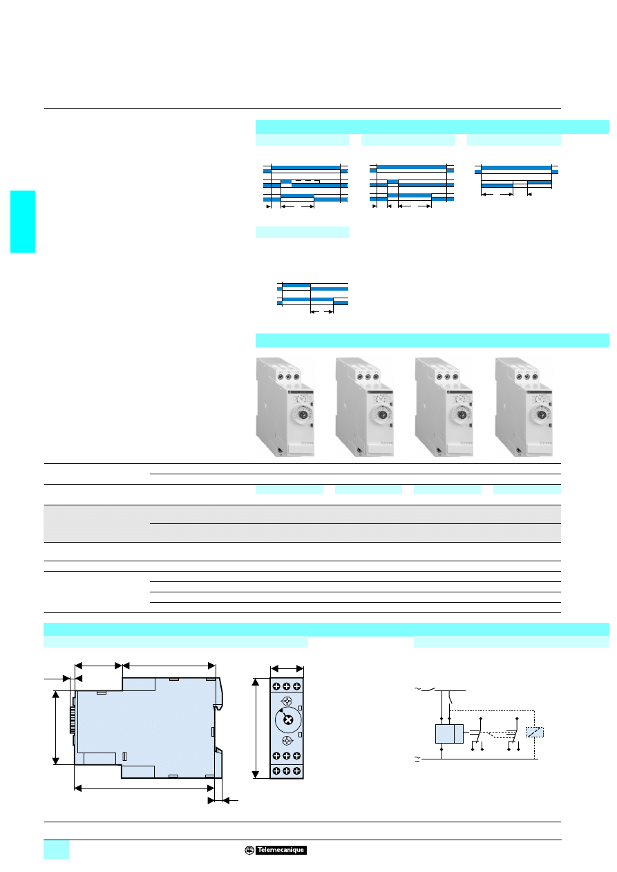
Function diagrams
Function A
Function H
Delay on energisation
Timing on energisation
References
Functions
Single function
Single function
A
H
Timing ranges
7 ranges
1 s - 10 s - 1 min - 10 min - 1 h - 10 h - 100 h
1 s - 10 s - 1 min - 10 min - 1 h - 10 h - 100 h
Voltages
2 24…240 V
–
RE11 LH BM
2/1 24…240 V
RE11 LA MW
–
Nominal output current
0.7 A
0.7 A
Connection
Screw terminals
5
5
Weight (kg)
0.060
0.060
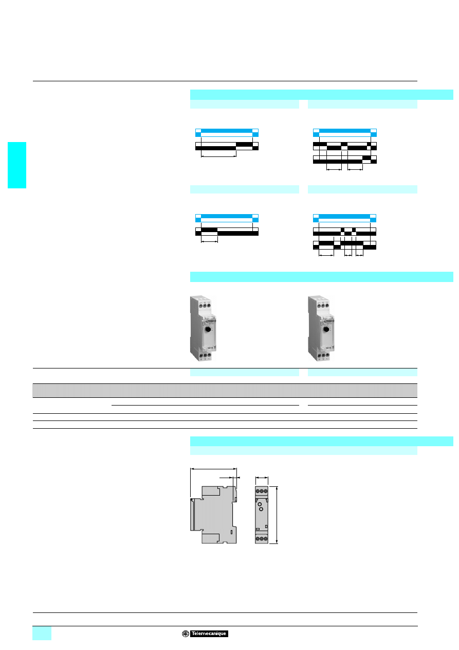
Dimensions and connection schemes
Dimensions
U
R
T
U
R
C
t1
t2
T
52
19
25
52
19
25
5,5
72
17,9
81
Characteristics :
pages 2/14 and 2/15
Schemes :
page 2/17
2/17
2
2
2
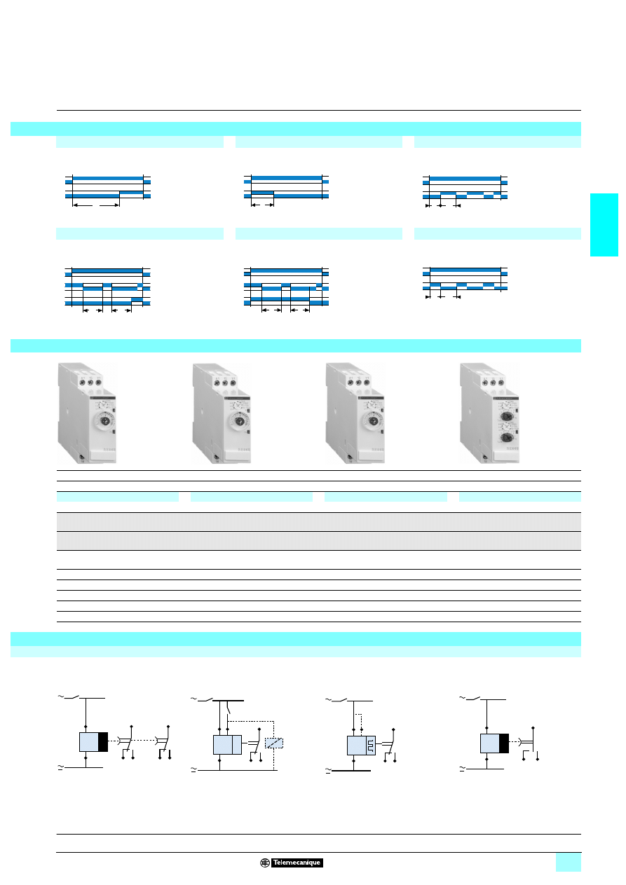
Function At
Function B
Function C
Function L
Function Li
Delay on energisation with
memory
T = t1 + t2 + …
Timing on impulse, one shot
Timing after opening
of control contact
Asymmetrical flashing, start
with output in rest position
Asymmetrical flashing, start
with output in operating
position
Function Ht
Function D
Function Di
Function Ac
Function Bw
Timing on energisation
with memory
T = t1 + t2 + …
Symmetrical flashing, start
with output in rest position
Symmetrical flashing, start
with output in operating
position
Timing after closing and
opening of control contact
Pulse output (width
adjustable)
Single function
Dual function
Multifunction
C
L - Li
A - At - B - C - H - Ht - D - Di - Ac - Bw
1 s - 10 s - 1 min - 10 min - 1 h - 10 h - 100 h
1 s - 10 s - 1 min - 10 min - 1 h - 10 h - 100 h
1 s - 10 s - 1 min - 10 min - 1 h - 10 h - 100 h
RE11 LC BM
RE11 LL BM
RE11 LM BM
–
–
–
0.7 A
0.7 A
0.7 A
5
5
5
0.060
0.060
0.060
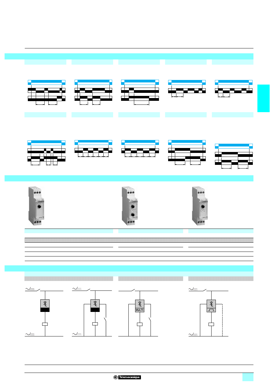
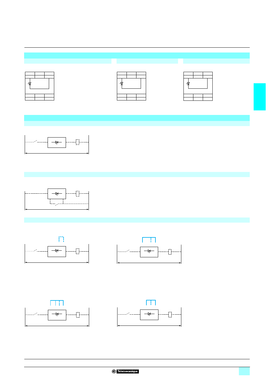
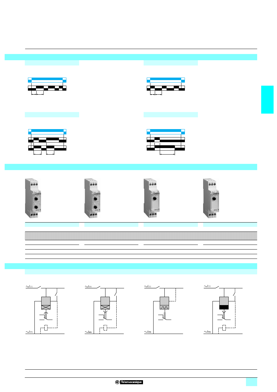
Connection schemes
Single function relay
Multifunction relay
Flashing
Functions A, H
Function C
(1) Contact Y1 :
- Control for functions B, C, Ac, Bw.
- Partial stop for functions At, Ht.
- Function D if Di selected.
- Not used for functions A and H.
Functions L, Li
(1) Link A2-Y1 for function L only.
U
R
C
t1
t2
U
R
C
T
T
U
C
R
T
Tr
Ta
U
R
Ta
Tr
U
R
U
R
C
t1
t2
T
T
T
T
T
T
T
U
R
T
T
T
T
T
U
R
U
C
R
T
T
U
R
C
T
T
52
19
26
52
19
27
5
219
28
R
A2/L
A1
U
±
±
R
LA
1
U
±
±
A2
Y2
Y2
R
A2
Y1
18
A1
U
Y1
(1)
a/c
a/c
(1)
R
A2
Y1
18
A1
U
Characteristics :
pages 2/14 and 2/15
Dimensions :
page 2/16
2/18
2
Characteristics
2
Zelio Time -
industrial timing relays
2
Single or multifunction relays, solid state output,
width 22.5 mm
The RE9 range of relays is designed for simple, repetitive applications with short and
intensive cycles because their solid state output provides very high electrical
durability.
Each relay has a single timing range.
Each relay has a wide voltage range from 24 to 240 V.
The range comprises 9 references with 3 model types:
1 RE9 TA: function A,
1 RE9 RA: function C,
1 RE9 MS: multifunction A, H, L, Li.
These products have a transparent, hinged flap on their front face to avoid any
accidental alteration of the settings. This flap can be directly sealed.
Presentation
56
08
53
Environment
Conforming to standards
IEC 61812-1, EN 61812-1
Product certifications
CSA, GL pending. UL
12
12
12
12marking
Zelio Time timing relays conform to European regulations relating to
4 marking
Ambient air temperature
around the device
Storage
°C
- 40…+ 85
Operation
°C
- 20…+ 60
Permissible relative
humidity range
Conforming to IEC 60721-3-3
15…85 % Environmental class 3K3
Vibration resistance
Conforming to IEC 60068-2-6,
10 to 55 Hz
a = 0.35 ms
Shock resistance
Conforming to IEC 60068-2-27
15 gn - 11 ms
Degree of protection
Casing
IP 50
Terminals
IP 20
Degree of pollution
Conforming to IEC 60664-1
3
Overvoltage category
Conforming to IEC 60664-1
III
Rated insulation voltage
Conforming to IEC
V
250
Conforming to CSA
V
300
Test voltage for
insulation tests
Dielectric test
kV
2.5
Shock wave
kV
4.8
Voltage limits
Power supply circuit
0.85…1.1 Uc
Frequency limits
Power supply circuit
Hz
50/60 ± 5 %
Disconnection value
Power supply circuit
> 0.1 Uc
Mounting position
without derating
In relation to normal
vertical mounting plane
Any position
Cabling
Maximum c.s.a.
Flexible cable without cable end mm
2
2 x 2.5
Flexible cable with cable end
mm
2
2 x 1.5
Tightening torque
N.m
0.6…1.1
Immunity to electromagnetic interference (EMC)
(application class 2 conforming to EN 61812-1)
Electrostatic discharge
Conforming to IEC 61000-4-2
Level 3 (6 kV contact, 8 kV air)
Electromagnetic fields
Conforming to IEC 61000-4-3
Level 3 (10 V/m)
Fast transients
Conforming to IEC 61000-4-4
Level 3 (2 kV)
Shock waves
Conforming to IEC 61000-4-5
Level 3 (2 kV)
Radiated and conducted
emissions
CISPR11
Group 1 class A
CISPR22
Class A
References :
page 2/20
Dimensions :
page 2/20
Schemes :
page 2/21
2/19
2
Characteristics
(continued)
2
Zelio Time -
industrial timing relays
2
Single or multifunction relays, solid state output,
width 22.5 mm
Timing relay type
RE9 TA
On-delay
RE9 RA
Off-delay
RE9 MS
Multifunction
Supply characteristics
Supply voltage
V
2/1 24…240
2 24…240
2/1 24…240.
See page 2/20
Voltage limits
Of the control circuit
0.85…1.1 Un
Frequency
Hz
50…60 ± 5 %
Control contact
Mechanical only
In series
Between Y2 and A2
In series
Maximum length of
connecting cable
From contact to RE9
m
–
20
–
Control input consumption
Input Y2
mA
–
5
–
Timing characteristics
Setting accuracy
< ± 20 %
Repeat accuracy
< 1 %
Minimum reset time
After the time delay period
ms
100
Minimum switching time
ms
–
40
–
Maximum immunity
to microbreaks
During the time delay period
ms
100
2
70
After the time delay period
ms
2
–
2
Temperature drift
≤ 0.1 % per degree centigrade
Switching characteristics (solid state type)
Maximum continuous current At ambient temperature: 20 °C
A
0.7 (minimum 10 mA)
Maximum overload current
VDE 0435 part. 303,
4.8.3/Class II
A
15 for 10 ms
Maximum voltage drop
Closed state
V
3 (at 0.7 A)
Leakage current
Open state
mA
≤ 6
≤ 1
≤ 6
Maximum dissipated power
W
2.5
4
2.5
Derating
For temperature > 20 °C
mA
Without
Electrical durability
In millions of operating cycles
> 100
References :
page 2/20
Dimensions :
page 2/20
Schemes :
page 2/21
2/20
2
Functions,
references,
dimensions
2
Zelio Time -
industrial timing relays
2
Single or multifunction relays, solid state output,
width 22.5 mm
Solid state output
1 Multifunction or single function
1 Multivoltage
1 Screw terminals
Function diagrams
Function A
Function C
Function H
Delay on energisation
Timing after opening
of control contact
Timing on energisation
Function D
Function Di
Symmetrical flashing,
start with output in rest
position
Symmetrical flashing,
start with output in
operating position
References
Functions
A
C
A, H, D, Di
Voltages
13or 2 24…240 V
5
–
53(A)
2324…240 V
–
5
53(H, D, Di)
Timing ranges
0.1 s…10 s
RE9 TA11MW
RE9 RA11MW7
RE9 MS21MW
0.3 s …30 s
RE9 TA31MW
RE9 RA31MW7
–
3 s…300 s
RE9 TA21MW
RE9 RA21MW7
RE9 MS21MW
40 s…60 min
RE9 TA51MW
RE9 RA51MW7
–
Weight (kg)
0.110
0.110
0.110
Dimensions
Rail mounting
Screw fixing
U
R
T
U
C
R
T
U
R
T
T
T
T
T
T
T
U
R
U
R
T
T
T
T
T
56
08
54
56
08
55
56
08
55
89,5
82
78
80
6
6
78
Characteristics :
pages 2/18 and 2/19
Schemes :
page 2/21
2/21
2
Schemes
2
Zelio Time -
industrial timing relays
2
Single or multifunction relays, solid state output,
width 22.5 mm
Terminal blocks
RE9 TA
RE9 RA
RE9 MS
Recommended application schemes
RE9 TA
The timing relay is placed in series, with the load whose energisation is to be delayed on one
side and switch K on the other side. The mains supply may be a.c. or d.c. and the voltage may
be between 24 V and 240 V. See function diagram on page opposite.
RE9 RA
The timing relay is placed in series with the load whose de-energisation is to be delayed. Switch
K is connected to terminals Y2 and A2 of the timing relay, and terminal A2 is connected to the
mains supply, as indicated in the diagram opposite. The device is operated from an a.c. mains
supply whose voltage is between 24 V and 240 V. See function diagram on page opposite.
RE9 MS
Delay on energisation
Function A
Timing on energisation
Function H
Selection of the timing range
X3-X4 not linked: range 3 s…300 s
(factory configuration)
X3-X4 linked: range 0.1 s…10 s
Link to be made between terminals X1 and X4
Symmetrical flasher,
start with output in rest position
Function D
Symmetrical flasher,
start with output in operating position
Function Di
Link to be made between terminals X2 and X4 on one side
and between X1 and X2 on the other side
Link to be made between terminals X1 and X4
Note : For supply voltages greater than 30 V, the rated voltage of the load is equal to the supply voltage. For a supply voltage of 24 V, the voltage drop within the
RE9 relay must be taken into account (about 3 V); a coil with a nominal voltage of 21 V must therefore be selected for the load.
A1
L
A1
L
Y2
A2
A1
L
X1
X3
X2
X4
L
A1
K
RE9-TA
Supply
1 or 2
Load
L
A1
K
A2
Y2
RE9-RA
Supply
1
Load
A2
L
A1
A1
K
X3 X4
RE9-MS
Supply
1 or 2
Load
A2
L
A1
A1
K
X1
X3 X4
RE9-MS
Supply
1
Load
A2
L
A1
A1
K
X2 X3
X1
X4
RE9-MS
Supply
1
Load
A2
L
A1
A1
K
X2 X3 X4
RE9-MS
Supply
1
Load
Characteristics :
pages 2/18 and 2/19
Dimensions :
page 2/20
2/22
2
Characteristics
2
Zelio Time -
modular timing relays
2
Relays with relay output,
width 17.5 mm
Timing characteristics
Relay type
RE11 R
3233
3233
3233
3233
RE11 RME MU
Selectable timing ranges
by selector switch on front panel
s
0.1…1
0.1…1
1…10
1…10
min
0.1…1
0.1…1
1…10
1…10
h
0.1…1
0.1…1
1…10
1…10
10…100
–
Repeat accuracy
(with constant parameters)
Conforming to IEC 61812-1
± 0.5 %
Drift
Temperature
± 0.05 % / °C
Voltage
± 0.2 % / V
Setting accuracy
at full scale
Conforming to IEC 61812-1
± 10 % at 25 °C
Minimum duration
of control pulse
Typical
ms
30
Typical with load in parallel
ms
100
Maximum reset time
by de-energisation
Typical
ms
100
Immunity to microbreaks
Typical
ms
> 10
Supply characteristics
Relay type
RE11 R
3233
3233
3233
3233
RE11 R
3333 JU
Supply voltage
V
2/1312…240
1324/2 24…240 depending on version
2/1 12 V
Frequency
Hz
50/60
Operating range
85…110 % of Un
90…120 % of Un
On-load factor
100 %
Maximum power
consumption
Depending
on model
2/1 12 V
VA/W
–
0.4
1 24 V
W
0.6
–
1 240 V
W
1.5
–
2 240 V
VA
32
–
Output characteristics
Relay type
RE11 R
3233
3233
3233
3233
RE11 RME MU
Output type
Relay, 1 C/O contact, AgNi (cadmium-free)
Breaking capacity
232000 VA, 1380 W
231250 VA, 1350 W
Maximum breaking current
A
238, 138
235, 135
Minimum breaking current
mA
10 /
1 10 V
Maximum switching voltage
V
2/13250 (except RE11 RMX MU: 2 250 and 1 150 )
Electrical life
10
5
operations 8 A 250 V resistive
10
5
operations 5 A 250 V resistive
Mechanical life
5 x 10
6
operations
Dielectric strength
Conforming to IEC 61812-1
kV
2.5/1min/1 mA/50 Hz
Impulse voltage
Conforming to IEC 60664-1,
IEC 61812-1
kV
5, wave: 1.2/50 µs
Display characteristics
State indication by 1 LED
Green
Operating status indication
Pulsing: relay energised, no timing in progress (except functions Di-D and Li-L)
Flashing: timing in progress
On steady: relay energised, no timing in progress
Input characteristics
Input type
Volt-free contact (no potential)
Control possible by 3-wire sensor with PNP output, maximum residual voltage: 0.4 V
whatever the supply voltage of the timer
References :
pages 2/23 and 2/24
Dimensions :
pages 2/24 and 2/26
Schemes :
pages 2/25 and 2/27
2/23
2
Characteristics
(continued)
2
Zelio Time -
modular timing relays
2
Relays with relay output,
width 17.5 mm
General characteristics
Conforming to standards
IEC 61812-1, EN 50081-1/2, EN 50082-1/2, LV directives (73/23/EEC + 93/68/EEC
(
4 marking) + EMC directive (89/336/EEC + IEC 60669-2-3)
Approvals
cULus, CSA,
GL except RE11 RMX MU and RE11 RME MU
Ambient air temperature
around the device
Storage
°C
- 30…+ 60
Operation
°C
- 20…+ 60
Creepage distance
and clearance
Conforming to IEC 60664-1
kV
4 kV/3
Degree of protection
conforming to IEC 60529
Terminal block
IP 20
Housing
IP 40
Front panel
IP 50
Vibration resistance
Conforming to IEC 60068-2-6
f = 10…55 Hz
A = 0.35 mm
Relative humidity
without condensation
Conforming to IEC 60068-2-3
93 %
Electromagnetic compatibility Immunity to
electrostatic discharge,
conforming to IEC 61000-4-2
Level III (Air 8 kV/Contact 6 kV)
Immunity to
electromagnetic fields,
conforming to ENV 50140/204
(IEC 61000-4-3)
Level III (10 V/m: 80 MHz…1 GHz)
Immunity to
fast transients in bursts,
conforming to IEC 61000-4-4
Level III (direct 2 kV / capacitive connecting clip 1 kV)
Immunity to
surges on the power supplies,
conforming to IEC 61000-4-5
Level III (common mode 2 kV / differential mode 1 kV)
Immunity to radio frequency
interference in common mode,
conforming to ENV 50141
(IEC 61000-4-6)
Level III (10 V rms: 0.15…80 MHz)
Immunity to
voltage dips and breaks,
conforming to IEC 61000-4-11
30 % / 10 ms
60 % / 100 ms
95 % / 5 s
Radiated and mains
conducted disturbance,
conforming to EN 55022
(EN 55011 Group 1)
Class B
Fixing
Symmetrical mounting rail
(EN 50022)
mm
35
Clamping capacity
Without cable end
mm
2
2 x 2.5 and 1 x 4
With cable end
mm
2
2 x 1.5
Spring terminals, 2 terminals
per connection point
Flexible cable
mm
2
1.5
Solid cable
mm
2
2.5
Housing material
Self-extinguishing
References :
pages 2/23 and 2/24
Dimensions :
pages 2/24 and 2/26
Schemes :
pages 2/25 and 2/27
2/24
2
Functions,
references,
dimensions,
schemes
2
Zelio Time -
modular timing relays
2
Relays with relay output,
width 17.5 mm
Output 1 C/O contact
1 Dual function or single function
1 Multi-range (7 selectable ranges)
1 Multivoltage
1 1 relay output: 8 A
1 Screw terminals
1 State indication by 1 LED
1 Option of supplying a load in parallel
1 3-wire sensor control option
Function diagrams
Function A
Function At
Delay on energisation
Delay on energisation with memory
T = t1 + t2 + …
Function H
Function Ht
Timing on energisation
Timing on energisation with memory
T = t1 + t2 + …
References
Functions
Dual function
Dual function
A - At
H - Ht
Timing ranges
7 ranges
1 s - 10 s - 1 min - 10 min - 1 h - 10 h - 100 h
1 s - 10 s - 1 min - 10 min - 1 h - 10 h - 100 h
Voltages
2/ 1 12 V
–
–
1324 V / 2 24…240 V
RE11 RA MU
RE11 RH MU
Nominal output current
8 A
8 A
Connection
Screw terminals
5
5
Weight (kg)
0.060
0.060
Dimensions and connection schemes
Dimensions
U
R
T
U
R
C
t1
t2
U
R
T
U
R
C
t1
t2
T
52
19
29
52
19
29
5,5
72
17,9
81
Characteristics :
pages 2/22 and 2/23
Schemes :
page 2/27
2/25
2
2
2
Function L
Function Li
Asymmetrical flashing,
start with output in rest position
Asymmetrical flashing,
start with output in operating position
Function B
Function C
Timing on impulse, one shot
Timing after opening
of control contact
Dual function
Dual function
Single function
Single function
L - Li
L - Li
B
C
1 s - 10 s - 1 min - 10 min - 1 h - 10 h -
100 h
1 s - 10 s - 1 min - 10 min - 1 h - 10 h -
100 h
1 s - 10 s - 1 min - 10 min - 1 h - 10 h -
100 h
1 s - 10 s - 1 min - 10 min - 1 h - 10 h -
100 h
–
RE11 RL JU
–
–
RE11 RL MU
–
RE11 RB MU
RE11 RC MU
8 A
8 A
8 A
8 A
5
5
5
5
0.060
0.060
0.060
0.060
Connection schemes
Functions A and At
Functions H and Ht
Functions L and Li
Functions B and C
(1) Link A1-Y1 for function L only.
Tr
Ta
U
R
Ta
Tr
U
R
U
R
C
T
T
U
C
R
T
52
19
30
52
19
30
52
19
29
5
2
1
9
2
9
A2
Y1
A1
U
+
–
16
15
R
18
A2
Y1
A1
U
+
–
16
15
R
18
A2
Y1
A1
U
+
–
16
15
R
18
(1)
A2
Y1
A1
U
+
–
16
15
R
18
Characteristics :
pages 2/22 and 2/23
Dimensions :
page 2/26
2/26
2
Functions,
references,
dimensions,
scheme
2
Zelio Time -
modular timing relays
2
Relays with relay output,
width 17.5 mm
Output 1 C/O contact
1 Multifunction
1 Multi-range (6 or 7 selectable ranges)
1 Multivoltage
1 1 relay output: 5 or 8 A
1 Screw or spring terminals
1 State indication by 1 LED
1 Option of supplying a load in parallel
1 3-wire sensor control option
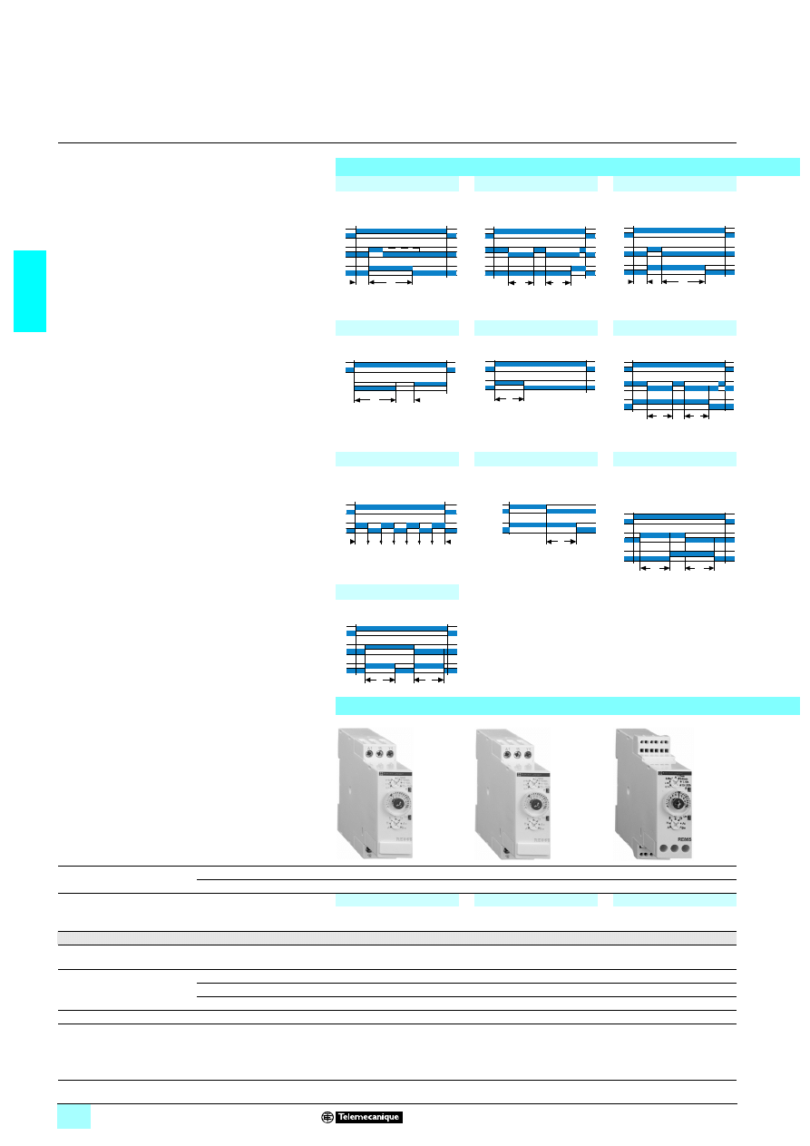
Function diagrams
Function A
Function At
Function B
Delay on energisation
Delay on energisation
with memory
T = t1 + t2 + …
Timing on impulse, one shot
Function C
Function H
Function Ht
Timing after opening
of control contact
Timing on energisation
Timing on energisation
with memory
T = t1 + t2 + …
Function D
Function Di
Function Ac
Symmetrical flashing, start
with output in rest position
Symmetrical flashing, start
with output in operating
position
Timing after closing and
opening of control contact
References
Functions
Multifunction
Multifunction
A - At - B - C - H - Ht - D - Di - Ac - Bw
A - At - B - C - H - Ht - D - Di - Ac - Bw
Timing ranges
6 or 7 ranges
1 s - 10 s - 1 min - 10 min - 1 h - 10 h - 100 h
1 s - 10 s - 1 min - 10 min - 1 h - 10 h - 100 h
Voltages
2/1312 V
–
–
1324 V / 2324…240 V
RE11 RM MU
–
2/1312…240 V
–
RE11 RM MW
Nominal output current
8 A
8 A
Connection
Screw terminals
5
5
Spring terminals
–
–
Weight (kg)
0.060
0.060
Dimensions and connection scheme
Dimensions
RE11 RM
3333 MU, RE11 RM MW, RE11 RM JU
RE11 RM MWS
U
R
T
U
R
C
t1
t2
U
R
C
T
T
U
C
R
T
U
R
T
U
R
C
t1
t2
T
T
T
T
T
T
T
U
R
T
T
T
T
T
U
R
U
C
R
T
T
52
19
31
52
19
31
5,5
72
17,9
81
5,5
72
17,9
81
Characteristics :
pages 2/22 and 2/23
Schemes :
page 2/25
2/27
2
2
2
Function Bw
Function Ad
Function Ah
Function N
Function O
Pulse output (width
adjustable)
Timing on closing
of control contact
Flashing single cycle by
operation of control contact
"Safe-guard"
"Delayed safe-guard"
Function P
Function Pt
Function T
Function Tt
Function W
Delayed fixed-length pulse
P = 500 ms
Impulse counter (on-delay)
T = t1 + t2 + …
P = 500 ms
Bistable relay
Timed impulse relay
On-delay after opening
of control contact
Multifunction
Multifunction
Multifunction
Multifunction
A - At - B - C - H - Ht - D - Di - Ac - Bw
A - At - B - C - H - Ht - D - Di - Ac - Bw
A - At - B - C - H - Ht - D - Di
Ad - Ah - N - O - P - Pt - T - Tt - W
1 s - 10 s - 1 min - 10 min - 1 h - 10 h - 100 h
1 s - 10 s - 1 min - 10 min - 1 h - 10 h - 100 h
1 s - 10 s - 1 min - 10 min - 1 h - 10 h
1 s - 10 s - 1 min - 10 min - 1 h - 10 h - 100 h
–
RE11 RM JU
–
–
–
–
RE11 RME MU
RE11 RMX MU
RE11 RM MWS
–
–
–
8 A
8 A
5 A
8 A
–
5
5
5
5
–
–
–
0.060
0.060
0.060
0.060
Connection scheme
(1) Contact Y1 :
- Control for functions B, C, Ac, Bw, Ad, Ah, N, O, W, T, Tt.
- Partial stop for functions At, Ht and Pt.
- Function D if Di selected.
- Not used for functions A, H and P.
U
R
C
T
T
U
R
C
T
T
U
R
C
T
T
T
T
T
U
C
R
T
T
T
U
C
R
t<T
U
R
T
P
t1
t2
P
U
G
R
U
C
R
U
C
R
T
t<T
T
U
C
R
52
19
32
52
19
31
52
19
31
52
19
33
A2
Y1
A1
U
+
–
16
15
R
18
Y1
(1)
Characteristics :
pages 2/22 and 2/23
Dimensions :
page 2/24
2/28
2
Characteristics
2
Zelio Time -
industrial timing relays
2
Single, dual or multifunction relays, relay output,
width 22.5 mm
Timing characteristics
Repeat accuracy
(with constant parameters)
Conforming to IEC 61812-1
± 0.5 %
Drift
Temperature
± 0.05 % / °C
Voltage
± 0.2 % / V
Full scale setting accuracy
Conforming to IEC 61812-1
± 10 % at 25 °C
Minimum duration
of control impulse
Typical
ms
30
Typical under load
ms
100
Maximum reset time
by de-energisation
Typical
ms
100
Immunity time
to microbreaks
Typical
ms
> 10
Supply characteristics
Multivoltage supply
Depending on version, see pages 2/30 to 2/33
Frequency
Hz
50/60
Operating range
85…110 % Un (85…120 Un for
2/1312 V )
On-load factor
100 %
Maximum power
consumption
Depending
on model
1 24 V
W
0.6
1 240 V
W
1.5
2 240 V
VA
32
Output characteristics
Output type
C/O contact, AgNi (cadmium-free)
Breaking capacity
232000 VA, 1380 W
Maximum breaking current
A
2/13 8
Minimum breaking current
mA
10 /
135 V
Maximum switching voltage
V
2/13250
Electrical durability
10
5
operations 8 A 250 V resistive
Mechanical durability
5 x 10
6
operations
Dielectric strength
Conforming to IEC 61812-1
kV
2.5/1 min/1 mA/50 Hz
Impulse voltage
Conforming to IEC 60064-1,
IEC 61812-1
kV
5, wave 1.2/50 µs
Display characteristics
State indication by 2 LEDs
Green
Operating status indication green LED
Pulsing: relay energised, no timing in progress
(except Di-D and Li-L)
Flashing: timing in progress
On steady: relay energised, no timing in progress
Yellow
On-delay relay
Input characteristics
Input type
Volt-free contact (no potential)
Control possible by 3-wire sensor with PNP output, maximum residual voltage: 0.4 V
whatever the supply voltage of the timer
References :
pages 2/30 to 2/33
Dimensions :
pages 2/30 to 2/33
Schemes :
pages 2/30 to 2/33
2/29
2
Characteristics
(continued)
2
Zelio Time -
industrial timing relays
2
Single, dual or multifunction relays, relay output,
width 22.5 mm
General characteristics
Conforming to standards
IEC 1812-1, EN 50081-1/2, EN 50082-1/2, LV directives (73/23/EEC + 93/68/EEC
(
4 marking) + EMC (89/336/EEC + IEC 669-2-3)
Product certifications
c UL us, CSA,
GL except RE 88 865 503 and RE 88 865 265
Temperature limits
Operation
°C
- 20…+ 60
Storage
°C
- 30…+ 60
Creepage distance
and clearance
Conforming to IEC 60664-1
kV
4 kV/3
Degree of protection
conforming to IEC 529
Terminal block
IP 20
Housing
IP 40
Front face
IP 50 except RE 88 865 265 (IP 30)
Vibration resistance
Conforming to IEC 68-2-6
f = 10…55 Hz
A = 0.35 mm
Relative humidity
without condensation
Conforming to IEC 68-2-3
93 %
Electromagnetic
compatibility
Immunity to
electrostatic discharge,
conforming to IEC 1000-42
Level III (Air 8 kV/Contact 6 kV)
Immunity to
electromagnetic fields,
conforming to ENV 50140/204
(IEC 1000-4-3)
Level III (10 V/m: 80 MHz…1 GHz)
Immunity to
fast transients in bursts,
conforming to IEC 1000-4-4
Level III (direct 2 kV / capacitive connecting clip 1 kV)
Immunity to
surges on the power supply,
conforming to IEC 1000-4-5
Level III (common mode 2 kV / differential mode 1 kV)
Immunity to radio frequency
interference in common mode
conforming to ENV 50141
(IEC 1000-4-6)
Level III (10 V rms: 0.15…80 MHz)
Immunity to
voltage dips and breaks,
conforming to IEC 1000-4-11
30 % / 10 ms
60 % / 100 ms
95 % / 5 s
Radiated and mains
conducted disturbance,
conforming to EN 55022
(EN 55011 Group 1)
Class B
Fixing
Symmetrical mounting rail
(EN 50022)
mm
35
Clamping capacity
Without cable end
mm
2
2 x 2.5
With cable end
mm
2
2 x 1.5
Spring terminals,
2 terminals per
connection point
Flexible cable
mm
2
1.5
Solid cable
mm
2
2.5
Housing material
Self-extinguishing
References :
pages 2/30 to 2/33
Dimensions :
pages 2/30 to 2/33
Schemes :
pages 2/30 to 2/33
2/30
2
Functions,
references,
dimensions,
schemes
2
Zelio Time -
industrial timing relays
2
Single, dual or multifunction relays, relay output,
width 22.5 mm
Relay outputs, 1 C/O and 2 C/O contacts
1 Single or dual function
1 Multi-timing range (7 switchable ranges)
1 Multivoltage
1 1 and 2 relay outputs: 8 A - 250 V (10 A UL)
1 Screw or spring terminals
1 State indication by 1 LED
1 Option of supplying a load in parallel
1 3-wire sensor control option
Function diagrams
Function B
Function C
Function Q
Timing on impulse, one shot
Off-delay
Star-delta starting
Function K
Delay on de-energisation
True Off-delay
(without auxiliary supply)
2 timed contacts
References
Connection
Screw terminals
5
5
5
5
Spring terminals
–
–
–
–
Functions
Single function
Single function
Single function
Single function
B
C
Q
K
Timing ranges
7 ranges
1 s - 10 s - 1 min - 10 min - 1 h - 10 h - 100 h
4 ranges
–
–
–
0.6 s - 2.5 s - 20 s -
160 s
Selectable interswitching time
–
–
20 - 40 - 60 - 80 -
100 - 120 - 140 ms
–
Relay output
1 timed contact
1 timed contact
1 timed contact
2 timed contacts
Voltages
1324 V / 2324…240 V
RE 88 865 125
RE 88 865 135
RE 88 865 175
RE 88 865 265
2/1312 V
–
–
–
–
2/1312…240 V
–
–
–
–
23230 / 380 V
–
–
RE 88 865 176
–
Weight (kg)
0.090
0.090
0.090
0.090
Dimensions and connection schemes
Dimensions
Connection schemes
All functions except K
RE 88 865 3
33
33
33
33 and RE 88 865 215
U
C
R
∞
T
U
C
R
∞
T
T
R
U
Ti
T
R1/R2
U
56
11
72
56
11
72
56
11
72
56
11
76
32
3,5
95
5
57
78
63
22,5
A1 15 Y1
18 16 A2
U
A1
R1
R2
15
A2
18
16
25/21
28/24
26/22
Y1
+
Characteristics :
pages 2/28 and 2/29
2/31
2
2
2
Function A
Function H
Function L
Delay on energisation
Timing on energisation
Asymmetrical recycler
Start after pause
Function At
Function Ht
Function Li
Timing on energisation with memory
Delay on energisation with memory
Asymmetrical recycler
Pulse start
5
5
5
5
–
–
–
–
Dual function
Dual function
Dual function
Dual function
A - At
A - At
H - Ht
Li - L
1 s - 10 s - 1 min - 10 min - 1 h - 10 h - 100 h
–
–
–
–
–
–
–
–
1 timed contact
2 timed contacts
1 timed contact
1 timed contact
RE 88 865 115
RE 88 865 215
RE 88 865 145
RE 88 865 155
–
–
–
–
–
–
–
–
–
–
–
0.090
0.090
0.090
0.090
Function K
RE 88 865 265
All functions except L and Li
RE 88 865 1
332
332
332
332
Functions L and Li
RE 88 865 155
Function Q
RE 88 865 17
3333
(1) Link A1-Y1 for function L only.
U
R
T
T
R
U
T1
R
T2
U
U
C
R
t1
t2
T = t1+t2
t1
R
C
U
t2
T = t1+t2
T1
R
U
T2
56
11
72
5
611
76
56
11
72
56
11
73
U
A1
A2
R1
R2
15
18
16
25
28
26
+
U
A1
R
15
A2
18
16
Y1
+
U
A1
R
15
(1)
A2
15
16
Y1
+
U
A1
R
15
A2
18
28
+
Characteristics :
pages 2/28 and 2/29
2/32
2
Functions,
references,
scheme
2
Zelio Time -
industrial timing relays
2
Single, dual or multifunction relays, relay output,
width 22.5 mm
Relay outputs, 1 C/O and 2 C/O contacts
1 Multifunction
1 Multi-timing range (7 switchable ranges)
1 Multivoltage
1 1 and 2 relay outputs: 8 A - 250 V (10 A UL) of which
1 convertible to instantaneous
1 Screw or spring terminals
1 State indication by 1 LED
1 Option of supplying a load in parallel
1 3-wire sensor control option
Function diagrams
Function A
Function At
Function B
Delay on energisation
Timing on energisation
with memory
Timing on impulse, one shot
Function C
Function H
Function Ht
Off-delay
Timing on energisation
Delay on energisation
with memory
Function Di
Function D
Function Ac
Flashing relay
Pulse start
Flashing relay
Start after pause
Timing after closing/opening
of control contact
Function Bw
Pulse output (adjustable)
References
Connection
Screw terminals
5
5
–
Spring terminals
–
–
5
Functions
Multifunction
Multifunction
Multifunction
A - At - B - C - H - Ht - Di - D -
Ac - Bw
A - At - B - C - H - Ht - Di - D -
Ac - Bw
A - At - B - C - H - Ht - Di - D -
Ac - Bw
Timing ranges
7 ranges
1 s - 10 s - 1 min - 10 min - 1 h - 10 h - 100 h
Relay output
1 timed contact
2 timed contacts, 1 of which
convertible to instantaneous
1 timed contact
Voltages
1324 V / 2324…240 V
RE 88 865 105
RE 88 865 305
–
2/1312 V
RE 88 865 100
RE 88 865 300
–
2/1312…240 V
RE 88 865 103
RE 88 865 303
RE 88 865 503
Weight (kg)
0.090
0.090
0.090
U
C
R
∞
T
U
C
R
t1
t2
T = t1+t2
U
C
R
∞
T
T
R
U
Ti
T
R
U
t1
R
C
U
t2
T = t1+t2
U
R
T T
T
R1/R2
U
U
C
R
T
T
U
C
R
T
T
56
11
71
56
11
75
56
11
74
Characteristics :
pages 2/28 and 2/29
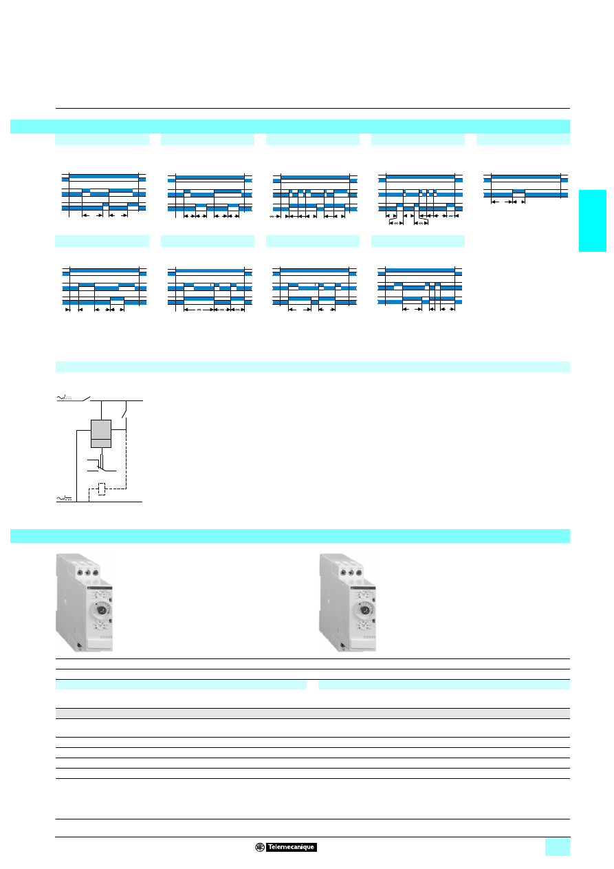
2/33
2
2
2
Function Ad
Function Ah
Function N
Function O
Function P
Delay on energisation
by switch
Flashing single cycle
by switch
"Safe-guard"
"Delayed safe-guard"
Delayed fixed-length pulse
Function Pt
Function TI
Function Tt
Function W
Impulse counter (on-delay)
Impulse relay
Timed impulse relay
Timing after pulse
on control contact
Connection scheme
5
5
–
–
Multifunction
Multifunction
Ad - Ah - N - O - P - Pt - Tl - Tt - W
Ad - Ah - N - O - P - Pt - Tl - Tt - W
1 timed contact
2 timed contacts
RE 88 865 185
RE 88 865 385
–
–
–
–
0.090
0.090
U
C
R
T
T
U
C
R
T
T
T
T
U
C
R
T
T
U
C
R
T
T
T
U
R
T
P
P = 500 ms
U
C
R
P
T = t1 + t2
P = 500 ms
t2
t1
U
C
R
U
C
R
T
t
U
C
R
T
T
A2
Y1
A1
U
+
–
16
15
R
18
56
11
71
56
11
71
Characteristics :
pages 2/28 and 2/29
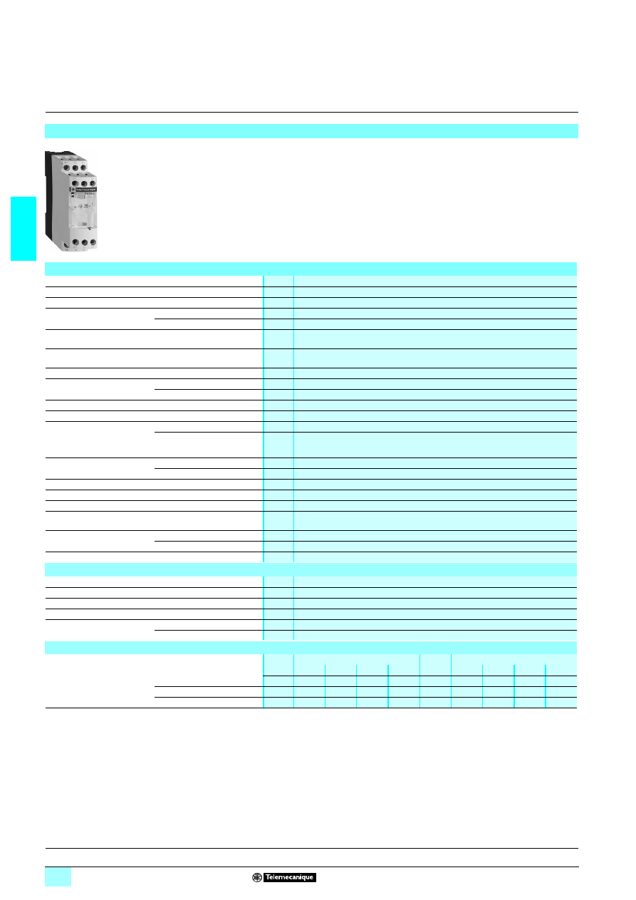
2/34
2
Characteristics
2
Zelio Time -
industrial timing relays
2
Single or multifunction relays, relay output,
width 22.5 mm
The RE7 range of relays, with only 23 references, covers all timing applications.
These relays offer multi-range timing from 50 ms to 300 h.
They are multivoltage.
Three models combine several different functions: multifunction relays.
These products have a transparent, hinged flap on their front face to avoid any
accidental alteration of the settings. This flap can be directly sealed.
Presentation
56
08
72
References :
pages 2/36 to 2/39
Environment
Conforming to standards
IEC 61812-1, EN 61812-1
Product certifications
CSA, GL pending, UL
1
1
1
1 marking
Zelio Time timing relays conform to European regulations relating to
4 marking
Ambient air temperature
around the device
Storage
°C
- 40…+ 85
Operation
°C
- 20…+ 60
Permissible relative
humidity range
Conforming to IEC 60721-3-3
15…85 % Environmental class 3K3
Vibration resistance
Conforming to IEC 60068-2-6,
10 to 55 Hz
a = 0.35 ms
Shock resistance
Conforming to IEC 60068-2-27
15 gn - 11 ms
Degree of protection
Casing
IP 50
Terminals
IP 20
Degree of pollution
Conforming to IEC 60664-1
3
Overvoltage category
Conforming to IEC 60664-1
III
Rated insulation voltage
Between contact circuit and
power supply or between contact
circuit and control inputs
Conforming to IEC
V
250
Conforming to CSA
V
300
Test voltage for
insulation tests
Dielectric test
kV
2.5
Shock wave
kV
4.8
Voltage limits
Power supply circuit
0.85…1.1 Uc
Frequency limits
Power supply circuit
Hz
50/60 ± 5 %
Disconnection value
Power supply circuit
> 0.1 Uc
Mounting position
without derating
In relation to normal
vertical mounting plane
Any position
Cabling
Maximum c.s.a.
Flexible cable without cable end mm
2
2 x 2.5
Flexible cable with cable end
mm
2
2 x 1.5
Tightening torque
N.m
0.6…1.1
Immunity to electromagnetic interference (EMC)
(application class 2 conforming to EN 61812-1)
Electrostatic discharge
Conforming to IEC 61000-4-2
Level 3 (6 kV contact, 8 kV air)
Electromagnetic fields
Conforming to IEC 61000-4-3
Level 3 (10 V/m)
Fast transients
Conforming to IEC 61000-4-4
Level 3 (2 kV)
Shock waves
Conforming to IEC 61000-4-5
Level 3 (2 kV)
Radiated and
conducted emissions
CISPR11
Group 1 class A
CISPR22
Class A
Consumption
2 50/60 Hz
1
Average consumption
24 V
48 V
110 V
240 V
24 V
48 V
110 V
240 V
RE7-
5511BU
VA
0.7
1.6
1.8
8.5
W
0.5
1.2
–
–
RE7-
5512BU and RE7-5513BU VA
1.2
2
2.8
12.5
W
0.8
1.6
–
–
RE7-
5555MW (1)
VA
2
2.5
3.2
6
W
2
1
3.2
2
(1) RE7-RB
11MW: current peak on energisation = 1 A / 30 ms.
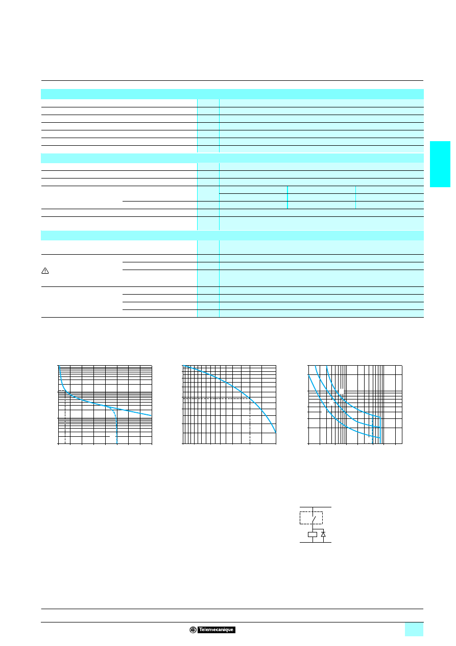
2/35
2
Characteristics
(continued)
2
Zelio Time -
industrial timing relays
2
Single or multifunction relays, relay output,
width 22.5 mm
Timing characteristics
Setting accuracy
As % of the full-scale value
± 10 %
Repeat accuracy
± 0.2 %
Influence of voltage
In the voltage range, 0.85…1.1 Un
< 0.2 %
Influence of temperature
< 0.07 %/°C
Immunity to microbreaks
ms
3
Minimum control pulse
ms
20 (except RE7-RB1
5MW: 1 s)
Reset time
ms
50
Output circuit characteristics
Maximum switching voltage
V
6 250
Mechanical durability
In millions of operating cycles
20
Current limit Ith
A
8 (except RE7-RB
55MW: 5 A)
Rated operational limits at 70 °C
Conforming to IEC 60947-5-1/1991
and VDE 0660
24 V
115 V
250 V
AC-15
A
3
3
3
DC-13
A
2
0.2
0.1
Minimum switching capacity
12 V/10 mA
Contact material
90/10 nickel silver
(except RE7-RB
55MU: gold flashed silver alloy)
Remote control input characteristics
Maximum voltage
Applicable to inputs
Y1Z2, X1Z2, X2Z2
V
60
Signal delivered by control
inputs Y1Z2, X1Z2, X2Z2
No galvanic insulation
between these inputs and the
supply
Switching current
mA
< 1
Maximum distance
m
50
Compatibility
3/4-wire PNP and NPN Telemecanique sensors or other sensors without an internal
load
Potentiometer for connection
between terminals Z1Z2, Z3Z2
Type
Linear at ± 20 %
Resistance
k
Ω
47 ± 20 %
Power
W
0.2
Maximum distance
m
25 by shielded cable: shielding linked to terminal Z2
References :
pages 2/36 to 2/39
a.c. load
d.c. load
Curve 1
Curve 2
Load limit curve
Electrical durability of contacts on resistive load
in millions of operating cycles
Reduction factor k for inductive loads (applies to
values taken from durability curve 1)
A
RE7-RB
33
33
33
33MW
A
RE7-RB
33
33
33
33MW
1
L/R = 20 ms
2
L/R with load protection diode
3
Resistive load
Example:
An LC1-F185 contactor supplied with 115 V/50 Hz for a consumption of 55 VA or a current consumption
equal to 0.1 A and cos
ϕ = 0.3.
For 0.1 A, curve 1 indicates a durability of approximately 1.5 million operating cycles.
As the load is inductive, it is necessary to apply a reduction coefficient k to this number of cycles as indicated
by curve 2.
For cos
ϕ = 0.3: k = 0.6
The electrical durability therefore becomes:
1.5 10
6
operating cycles x 0.6 = 900 000 operating cycles.
10
1
0,1
0,01
0
1
2
3
4
5
6
7
8
A
Current broken in A
M
illion
s
of op
er
atin
g cycles
Power factor on breaking (cos
ϕ)
1
0,6
0,5
0,9
0,8
0,7
0,4
0,3
1
0,8
0,6 0,5
0,4
0,3
0,2
R
edu
cti
on fact
or k
300
40
30
200
100
50
20
10
0,1
0,2
0,5
1
2
5
20
10
1
2
3
A
Current in A
V
o
lt
age i
n
V
RE7
K
+
–
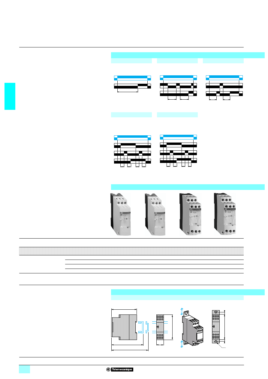
2/36
2
Functions,
references,
dimensions,
schemes
2
Zelio Time -
industrial timing relays
2
Single or multifunction relays, relay output,
width 22.5 mm
Output 1 C/O contact
Multiple timing ranges
Function diagrams
Function A
Function At
Function Aw
Delay on energisation
Delay on energisation
with memory
Off-delay on energisation
or on opening of control
contact
T = t1 + t2 + …
Function Ac
Function Ak
Timing after closing and
opening of control
contact
Asymmetrical On-delay
and Off-delay with
external control
T = t1 + t2 + …
T = t’1 + t’2 + …
Ta = t1 + t2 + …
Tr = t’1 + t’2 + …
References
Functions
A
A, Aw, At
Ac
Ak
Timing ranges
0.05 s…300 h
10 ranges
0.05 s…300 h
10 ranges
0.05 s…300 h
10 ranges
0.05 s…300 h
10 ranges
Voltages
13or 2 24 V
5
5
5
5
23110…240 V
5
5
5
5
2 or 1 42…48 V
–
5
5
5
13or 2 24…240 V
–
–
–
–
References
RE7 TL11BU
RE7 TM11BU
RE7 MA11BU
RE7 MV11BU
Weight (kg)
0.150
0.150
0.150
0.150
Dimensions and connection schemes
Dimensions
Rail mounting
Screw fixing
U
R
T
U
R
C
t1
t2
U
R
C
T
T
U
C
t1
G
R
t'1
t2
t'2
U
C
t1
G
R
t'1
t2
t'2
5
6
0
873
56
08
73
56
08
74
560
87
4
89,5
80
82
22,5
78
6
6
78
Ø4
Characteristics :
pages 2/34 and 2/35
Schemes :
pages 2/40 and 2/41
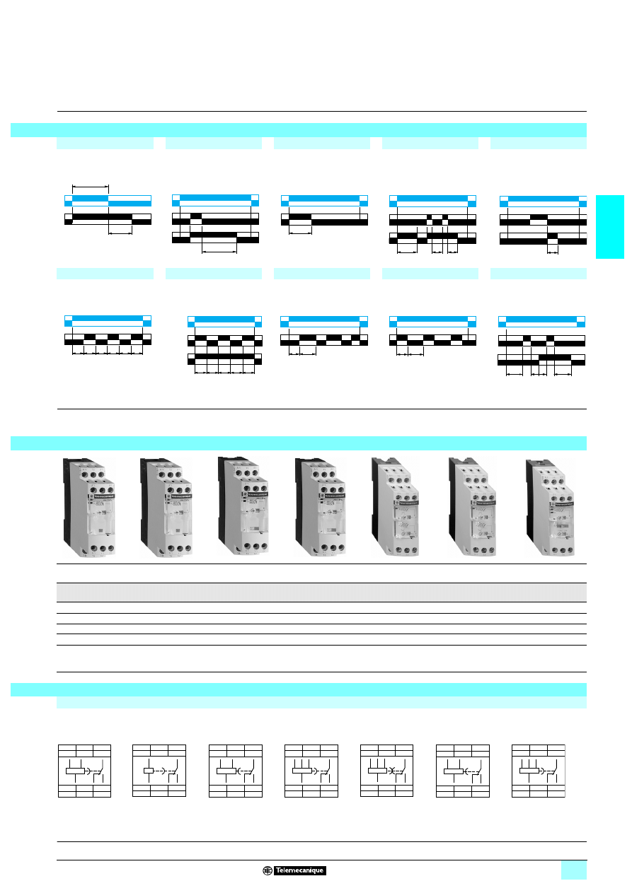
2/37
2
2
2
Function K
Function C
Function H
Function Ht
Function W
Delay on de-energisation
(without auxiliary supply)
Timing after opening
of control contact
Timing on energisation
Timing on energisation
with memory
On-delay after opening
of control contact
T + t1 + t2 + …
Function D
Function Di
Function L
Function Li
Function Lt
Symmetrical flashing,
start with output in
rest position
Symmetrical flashing,
start with output in
operating position
Asymmetrical flashing,
start with output in
rest position
Asymmetrical flashing,
start with output in
operating position
A
symmetrical flashing
with partial stop of timing
Tr = t1 + t2 + …
Ta = t’1 + t’2 + …
(1) If the device has been stored, de-energised, for more than a month, it must be energised for about 15 seconds in order to activate it. Subsequently, it only takes
1 second to start the time delay.
2 If this time is not complied with, the relay remains energised indefinitely.
(2) 2 timed outputs (R1/R2) or 1 timed output (R1) and 1 instantaneous output (R2 inst.).
K
C
H
Ht, W
D
L, Li, Lt
A, C, H, W, D, Di
0.05 s…10 min
7 ranges
0.05 s…300 h
10 ranges
0.05 s…300 h
10 ranges
0.05 s…300 h
10 ranges
0.05 s…300 h
10 ranges
0.05 s…300 h
10 ranges
0.05 s…300 h
10 ranges
–
5
5
5
5
5
5
–
5
5
5
5
5
5
–
5
–
5
–
5
5
5
–
–
–
–
–
–
RE7 RB11MW
RE7 RA11BU
RE7 RM11BU
low level contact
RE7 PE11BU
RE7 PM11BU
RE7 CL11BU
RE7 CV11BU
RE7 ML11BU
0.150
0.150
0.150
0.150
0.150
0.150
0.150
Connection schemes
RE7 TL11BU
RE7 RB11MW
RE7 PE11BU
RE7 TM11BU,
RE7 RA11BU
RE7 RM11BU,
RE7 PM11BU
RE7 MA11BU
RE7 MV11BU
RE7 CL11BU
RE7 CV11BU
U
R
T
> 1 s (1)
U
C
R
T
U
R
T
U
R
C
t1
t2
T
T
U
C
R
T
T
T
T
T
T
U
R
U
R1/R2
T
T
T
T
T
R
2
inst.
(2)
Tr
Ta
U
R
Ta
Tr
U
R
R
G
t1
t’2
t2 t’1
U
56
08
75
56
08
75
56
08
76
56
08
76
56
08
77
56
08
77
56
09
08
A1
15
B1
18
16
A2
18
15
B1
A1
A2
16
A1
15
18
16
A2
18
15
A1
A2
16
A1
15
B1
18
16
A2
18
15
B1
A1
A2
16
A1
15
B1
Z1
B2
Y1
X1
Z2
18
16
A2
18
15
B1
A1
B2
A2
16
A1
15
B1
Z1
B2
Y1
X1
Z2
18
16
A2
18
15
B1
A1
B2
A2
16
A1
15
B1
18
16
A2
18
15
B1
A1
A2
16
A1
15
B1
Z3
Z1
B2
X2
X1
Z2
18
16
A2
18
15
B1
A1
B2
A2
16
Characteristics :
pages 2/34 and 2/35
Dimensions :
page 2/36
Schemes :
pages 2/40 and 2/41
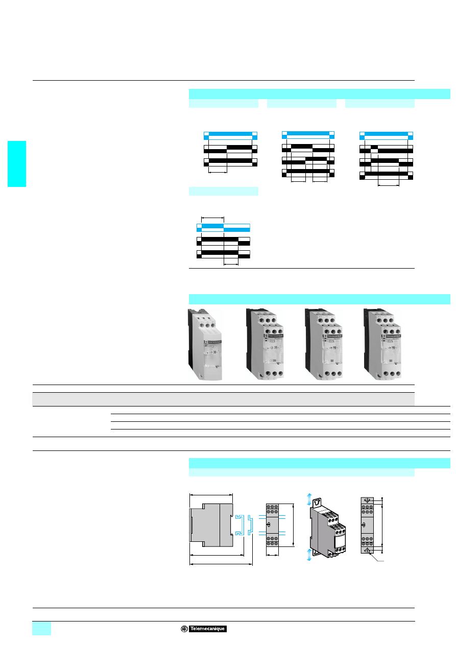
2/38
2
Functions,
references,
dimensions,
schemes
2
Zelio Time -
industrial timing relays
2
Single or multifunction relays, relay output,
width 22.5 mm
Output 2 C/O contacts
Multiple timing ranges
Function diagrams
Function A
Function Ac
Function C
Delay on energisation
Timing after closing and
opening of control contact
Timing after opening
of control contact
Function K
Delay on de-energisation
(without auxiliary supply)
(1) 2 timed outputs (R1/R2) or 1 timed output (R1) and 1 instantaneous output (R2 inst.).
(2) If the device has been stored, de-energised, for more than a month, it must be energised for
about 15 seconds in order to activate it. Subsequently, it only takes 1 second to start the time
delay.
2 If this time is not complied with, the relay remains energised indefinitely.
References
Functions
A
Ac
C
K
Timing ranges
0.05 s…300 h
10 ranges
0.05 s…300 h
10 ranges
0.05 s…300 h
10 ranges
0.05 s…10 min
7 ranges
Voltages
13or 2 24 V
5
5
5
–
23110…240 V
5
5
5
–
2 or 1 42…48 V
5
5
5
–
13or 2 24…240 V
–
–
–
5
References
RE7 TP13BU
RE7 MA13BU
symmetrical
RE7 RL13BU
low level contact
RE7 RB13MW
Weight (kg)
0.150
0.150
0.150
0.150
Dimensions and connection schemes
Dimensions
Rail mounting
Screw fixing
U
R1/R2
T
R2
inst.
(1)
U
C
R1/R2
T
T
R2
inst.
(1)
U
R1/R2
C
T
R2
inst.
(1)
U
R1
R2
T
> 1 s (2)
56
09
02
56
09
03
56
09
04
56
09
04
89,5
80
82
22,5
78
6
6
78
Ø4
Characteristics :
pages 2/34 and 2/35
Schemes :
pages 2/40 and 2/41
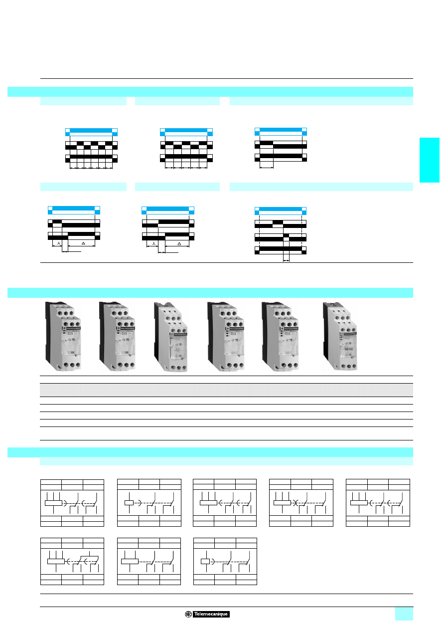
2/39
2
2
2
Function D
Function Di
Function H
Symmetrical flashing,
start with output in
rest position
Symmetrical flashing,
start with output in
operating position
Timing on energisation
Function Qg
Function Qt
Function W
Star-delta timing
Star-delta timing
On-delay after
opening of control contact
(1) 2 timed outputs (R1/R2) or 1 timed output (R1) and 1 instantaneous output (R2 inst.).
H
W
D
Qt
Qg
A, C, H, W, D, Di, Qg, Qt
0.05 s…300 h
10 ranges
0.05 s…300 h
10 ranges
0.05 s…300 h
10 ranges
0.05 s…300 h
10 ranges
0.05 s…300 h
10 ranges
0.05 s…300 h
10 ranges
5
5
5
5
5
5
–
5
5
5
5
5
5
–
5
5
5
5
5
5
–
–
–
–
–
–
–
5
RE7 PP13BU
RE7 PD13BU
RE7 CP13BU
RE7 YA12BU
RE7 YR12BU
RE7 MY13BU
RE7 MY13MW
0.150
0.150
0.150
0.150
0.150
0.150
0.150
Connection schemes
RE7 TP13BU
RE7 RB13MW
RE7 YA
RE7 RL13BU, RE7 MA13BU
RE7 PD13BU
RE7 PP13BU
RE7 CP13BU
RE7 YR
RE7 MY13BU
RE7 MY13MW
U
R1/R2
T
T
T
T
T
T
R
2
inst. (1)
U
R1/R2
T
T
T
T
T
R
2
inst. (1)
U
R1/R2
T
R
2
inst. (1)
T
T
50 ms
U
R1
R2
U
R1
R2
T
T
50 ms
U
C
R1/R2
T
R
2
inst. (1)
56
09
05
56
09
05
56
09
06
56
09
07
56
09
07
56
09
08
56
09
08
A1
15
B1
25 (21)
Z1
B2
28 (24)
Z2
18
26 (22)
16
A2
18
15
B1
A1
B2
A2
16
28
25
(21)
26
(24)
(22)
A1
15
25
Z1
26
Z2
28
18
16
A2
18
15
A1
A2
16
28
25
26
A1
15
B1
25
B2
28
26
Z2
18
16
A2
18
15
B1
A1
B2
A2
16
28
25
26
A1
15
B1
25 (21)
Y1
B2
26 (22)
28 (24)
Z2
18
16
A2
18
15
B1
A1
B2
A2
16
28
25
26
(24)
(21)
(22)
A1
15
B1
25 (21)
Z1
B2
26 (22)
28 (24)
Z2
18
16
A2
18
15
B1
A1
B2
A2
16
28
25
26
(24)
(21)
(22)
B1
17
17
A1
B2
28
26
Z2
18
16
A2
18
B1
A1
B2
A2
16
28
17
26
A1
15
B1
25 (21)
Z1
Y1
26 (22)
28 (24)
Z2
18
16
A2
18
15
B1
A1
A2
16
28
(24)
25
(21)
26
(22)
A1
15
Y1
25 (21)
Z1
X1
26 (22)
28 (24)
Z2
18
16
A2
18
15
A1
A2
16
28
25
26
(24)
(21)
(22)
Characteristics :
pages 2/34 and 2/35
Dimensions :
page 2/38
Schemes :
pages 2/40 and 2/41
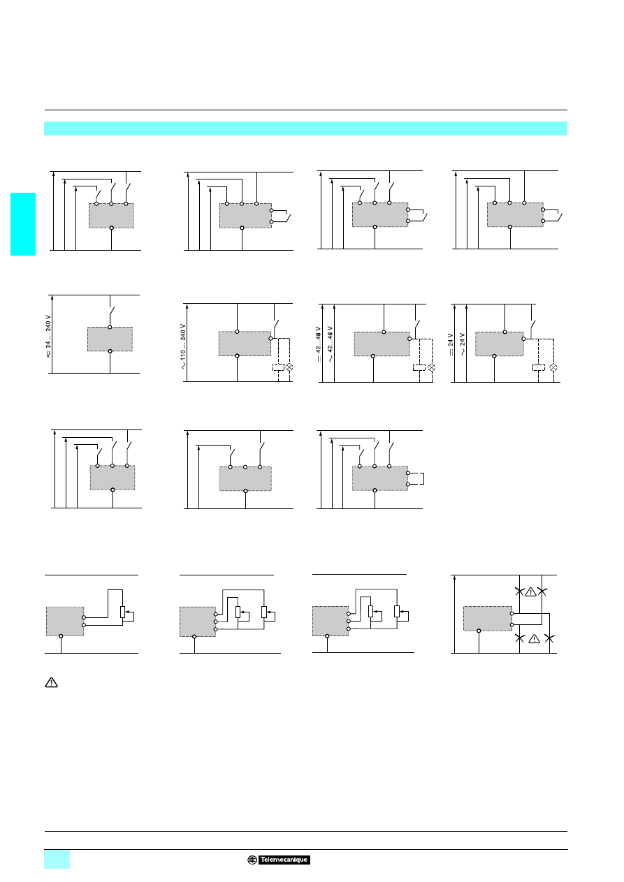
2/40
2
Schemes
2
Zelio Time -
industrial timing relays
2
Single or multifunction relays, relay output,
width 22.5 mm
Recommended application schemes
RE7 TL, TM, TP, CL, CP, ML, MY
Start on energisation
RE7 TM, MA, MV, RM, RL, PM, PD,
ML, MY
Start by external control
RE7 TM, PM, ML, MY
External control of partial stop
RE7 MA, MV, RA, RM
Start by external control
RE7 RB
Start on de-energisation
RE7 RA
Start by external control
RE7 PP
Start on energisation
RE7 PE
Start on energisation
RE7 CV
Selection of starting phase
RE7 TM, TP, MA, RA, RM, PP, PM,
ML, MY
Connection of potentiometer
RE7 MV
Connection of potentiometers to
asymmetrical timing relays
RE7 CV
Connection of potentiometers
Connection precautions
No galvanic isolation between supply terminals A1, A2, B1, B2 and control inputs X1, Y1, Z1, Z2.
(1)
3 110…240 V except RE7 MY13MW :45424…240 V
(2)
54 12…48 V
(3)
54 24 V
(4) Adjustment of the On-delay period
(5) Adjustment of the Off-delay period
(6) Start during the On-delay period : X2, Z2 linked. Start during the Off-delay period : X2, Z2 not linked
(7) Off-delay adjustment (tr) (contact 15/16 closed)
(8) On-delay adjustment (ta) (contact 15/18 closed)
B1
A1
B2
A2
(1)
(2)
(3)
B1
A1
B2
A2
Y1
Z2
(1)
(2)
(3)
B1
A1
B2
A2
X1
Z2
(1)
(2)
(3)
B1
A1
B2
A2
X1
Z2
(1)
(2)
(3)
A1
A2
A1
A2
Y1
B2
A2
Y1
+
–
B1
A2
Y1
+
–
B1
A1
B2
A2
(1)
(2)
(3)
B1
B3
B2
A2
(1)
(3)
B1
A1
B2
A2
X2
Z2
(6)
(1)
(2)
(3)
Z1
Z2
A2
Z1
Z3
(4)
(5)
Z2
A2
Z1
Z3
(7)
(8)
Z2
A2
A2
Z2
S
upp
ly
X1 or Y1 or Z1
Characteristics :
pages 2/34 and 2/35
References :
pages 2/36 to 2/39
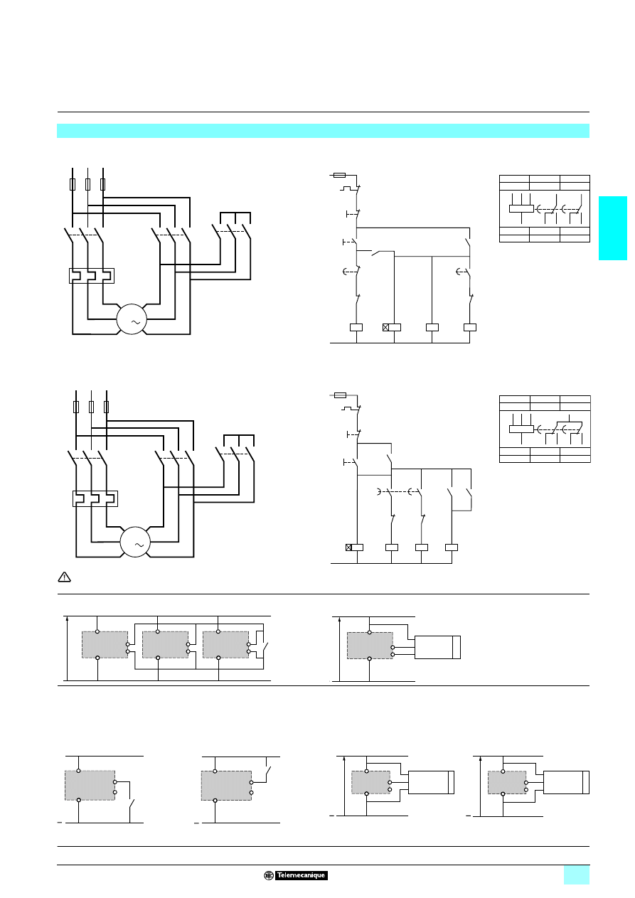
2/41
2
Schemes
(continued)
2
Zelio Time -
industrial timing relays
2
Single or multifunction relays, relay output,
width 22.5 mm
Recommended application schemes
(continued)
Power scheme
RE7 YA12BU
Control schemes
Star-delta function with double On-delay timing Qt
Power scheme
RE7 YR12BU
Control schemes
Star-delta function with contact for switching to star connection Q
No galvanic isolation between supply terminals A1, A2, B1, B2 and supply terminal Z2.
This terminal must therefore never be used (factory setting).
Control of several relays with a single external control contact
Connection of a Telemecanique 3-wire NPN or PNP sensor
It is advisable to follow the recommended wiring schemes detailed above and on previous pages. However, the connections below are possible if the restrictions
given are taken into account.
Connection of an external control contact without using terminal Z2:
Connection of a Telemecanique 3-wire NPN or PNP sensor without using
terminal Z2:
- possible on all RE7 relays with external control option except RE7 RA11BU,
- d.c. supply only.
- only possible on relay RE7
5555BU,
- d.c. supply only
.
V2
W2
U2
W1
V1
U1
F2
K2
1
2
3
4
5
6
K1
1
2
3
4
5
6
M1
K3
1
2
3
4
5
6
L1
L2
L3
1
2
3
4
5
6
3
K1
A1
A2
96
F2
15
16
K1T
21
22
K3
21
22
13
14
S1
S2
K1T
A1
A2
13
14 K1
K2
A1
A2
K3
A1
A2
25
28
K1T
21
22
K1
14
13
K2
A1
15
B1
25
B2
28
26
Z2
18
16
A2
18
15
B1
A1
B2
A2
16
28
25
26
Y
N
Δ
95
F3
Terminal block
K1T = relay RE7 YA
V2
W2
U2
W1
V1
U1
F2
K2
1
2
3
4
5
6
K1
1
2
3
4
5
6
M1
K3
1
2
3
4
5
6
L1
L2
L3
1
2
3
4
5
6
3
K1
A1
A2
95
96
F2
21
22
K3
F3
21
22
13
14
S1
S2
K1T
A1
A2
K3
A1
A2
K2
A1
A2
14
13
53
54
K2
28
17
21
22
K1
18
17
K1T
K2
14
13
K1
B1
17
17
A1
B2
28
26
Z2
18
16
A2
18
B1
A1
B2
A2
16
28
17
26
Y
N
Δ
Terminal block
K1T = relay RE7 YR
Z2
A2
Z2
A2
Z2
A2
Su
p
p
ly
A1,B1 or B12
Y1 or X1
A1,B1 or B12
Y1 or X1
A1,B1 or B12
Y1 or X1
BN
BK
NPN
PNP
BU
+
Z2
A2
Su
p
p
ly
A1,B1 or B12
Y1 or X1
+
Z2
A2
A1,B1 or B12
Y1 or X1
+
Z2
A2
A1,B1 or B12
Y1 or X1
BN
BK
NPN
BU
Y1
+
B1B2
Z2
A2
24
or
48 V
BN
BK
PNP
BU
Y1
+
B1B2
Z2
A2
24
or
48 V
Characteristics :
pages 2/34 and 2/35
References :
pages 2/36 to 2/39
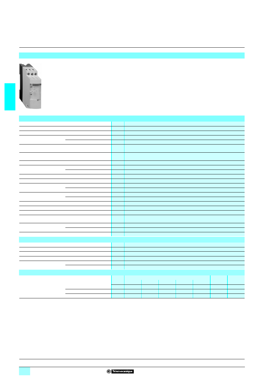
2/42
2
Characteristics
2
Zelio Time -
industrial timing relays
2
Optimum single-function relays, relay output,
width 22.5 mm
The RE8 range of relays is designed for simple and repetitive applications, providing
basic functions.
Each relay comprises:
- a single timing range,
- a C/O output relay.
These products have a transparent, hinged flap on their front face to avoid any
accidental alteration of the settings. This flap can be directly sealed.
Presentation
56
09
53
Environment
Conforming to standards
IEC 61812-1. EN 61812-1
Product certifications
CSA, GL pending. UL
12
12
12
12marking
Zelio Time timing relays conform to European regulations relating to
4 marking
Ambient air temperature
around the device
Storage
°C
- 40…+ 85
Operation
°C
- 20…+ 60
Permissible relative
humidity range
Conforming to IEC 60721-3-3
15…85 % Environmental class 3K3
Vibration resistance
Conforming to IEC 60068-2-6,
10 to 55 Hz
a = 0.35 ms
Shock resistance
Conforming to IEC 60068-2-27
15 gn - 11 ms
Degree of protection
Casing
IP 50
Terminals
IP 20
Degree of pollution
Conforming to IEC 60664-1
3
Overvoltage category
Conforming to IEC 60664-1
III
Rated insulation voltage
Conforming to IEC
V
250
Conforming to CSA
V
300
Test voltage for
insulation tests
Dielectric test
kV
2.5
Shock wave
kV
4.8
Voltage limits
Power supply circuit
0.9…1.1 Uc
Frequency limits
Power supply circuit
Hz
50/60 ± 5 %
Disconnection value
Power supply circuit
> 0.1 Uc
Mounting position
without derating
In relation to normal
vertical mounting plane
Any position
Connection
maximum c.s.a.
Flexible cable without cable end mm
2
2 x 2.5
Flexible cable with cable end
mm
2
2 x 1.5
Tightening torque
N.m
0.6…1.1
Immunity to electromagnetic interference (EMC)
(application class 2 conforming to EN 61812-1)
Electrostatic discharge
Conforming to IEC 61000-4-2
Level 3 (6 kV contact, 8 kV air)
Electromagnetic fields
Conforming to IEC 61000-4-3
Level 3 (10 V/m)
Fast transients
Conforming to IEC 61000-4-4
Level 3 (2 kV)
Shock waves
Conforming to IEC 61000-4-5
Level 3 (2 kV)
Radiated and conducted
emissions
CISPR11
Group 1 class A
CISPR22
Class A
Consumption
Consumption
2
1
24 V
110 V
240 V
380 V
415 V
24 V
RE8-TA, RA, CL, PE, PU, PT
VA
0.7
1.8
8.5
–
–
W
0.5
RE8-YG, RB
VA
0.9
2.5
13
–
–
W
0.5
RE8-YA
VA
0.9
2.5
13
8
9
W
0.7
References :
pages 2/44 to 2/47
Dimensions :
pages 2/44 and 2/46
Schemes :
page 2/45
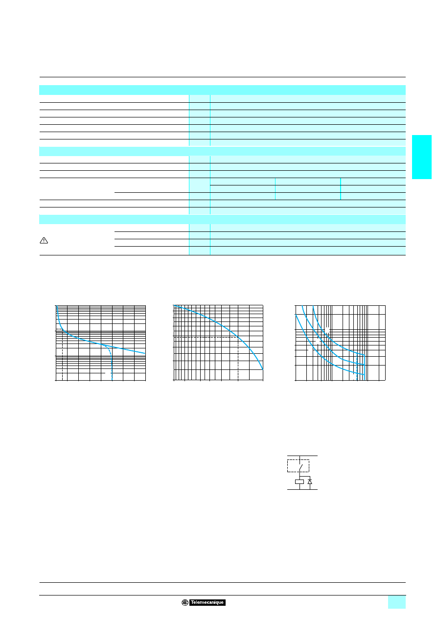
2/43
2
Characteristics
(continued)
2
Zelio Time -
industrial timing relays
2
Optimum single-function relays, relay output,
width 22.5 mm
Timing characteristics
Setting accuracy
As % of the full-scale value
± 20 %
Repeat accuracy
< 1 %
Influence of voltage
In the voltage range, 0.9…1.1 Un
< 2.5 %
Influence of temperature
< 0.2 %/°C
Immunity to microbreaks
ms
3
Minimum control pulse
ms
26 (except RE8-YG: 60)
Reset time
ms
50
Output circuit characteristics
Maximum switching voltage
V
6 250
Mechanical durability
In millions of operating cycles
20
Current limit Ith
A
8
Rated operational limits at 70 °C
Conforming to IEC 60947-5-1/1991
and VDE 0660
24 V
115 V
250 V
AC-15
A
3
3
3
DC-13
A
2
0.2
0.1
Minimum switching capacity
12 V/10 mA
Contact material
90/10 nickel silver
Remote control input characteristics
Signal delivered by control
input Y1
No galvanic insulation
between this input and the
supply
No-load voltage
Supply voltage
Switching current
mA
< 10
Maximum distance
m
50
Compatibility
2-wire sensors
1 with leakage current < 1 mA
References :
pages 2/44 to 2/47
Dimensions :
pages 2/44 and 2/46
Schemes :
page 2/45
a.c. load
d.c. load
Curve 1
Curve 2
Load limit curve
Electrical durability of contacts on resistive load
in millions of operating cycles
Reduction factor k for inductive loads (applies to
values taken from durability curve 1)
A
RE8-RB
55BUTQ
A
RE8-RB
55BUTQ
1
L/R = 20 ms
2
L/R with load protection diode
3
Resistive load
Example:
An LC1-F185 contactor supplied with 115 V/50 Hz for a consumption of 55 VA or a current consumption
equal to 0.1 A and cos
ϕ = 0.3.
For 0.1 A, curve 1 indicates a durability of approximately 1.5 million operating cycles.
As the load is inductive, it is necessary to apply a reduction coefficient k to this number of cycles as indicated
by curve 2.
For cos
ϕ = 0.3: k = 0.6
The electrical durability therefore becomes:
1.5 10
6
operating cycles x 0.6 = 900 000 operating cycles.
10
1
0,1
0,01
0
1
2
3
4
5
6
7
8
A
Current broken in A
M
illions of
oper
ating cycle
s
1
0,6
0,5
0,9
0,8
0,7
0,4
0,3
1
0,8
0,6 0,5
0,4
0,3
0,2
Power factor on breaking (cos
ϕ)
R
e
duction
factor
k
300
40
30
200
100
50
20
10
0,1
0,2
0,5
1
2
5
20
10
1
2
3
A
Current in A
V
o
lt
age i
n
V
RE8
K
+
–
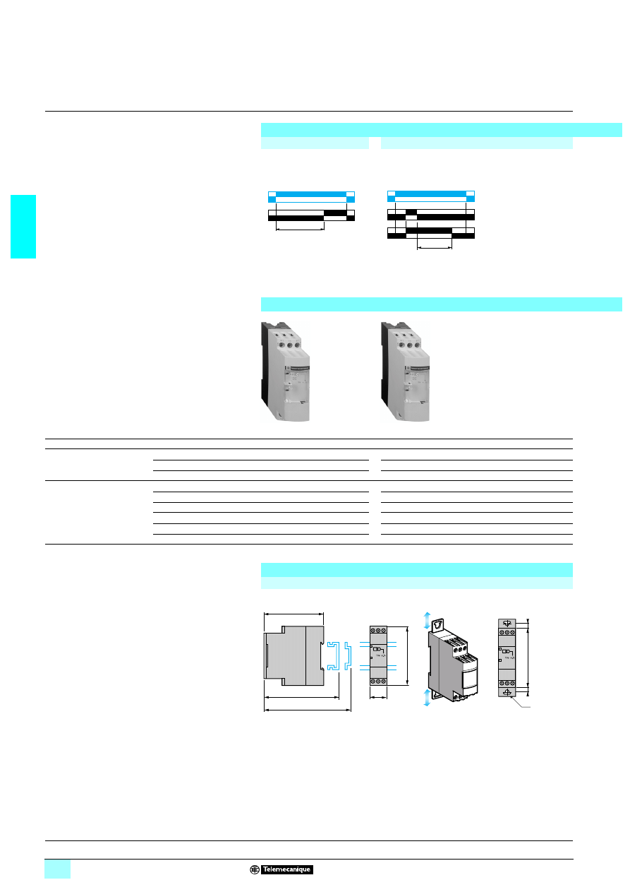
2/44
2
Functions,
references,
dimensions,
schemes
2
Zelio Time -
industrial timing relays
2
Single-function relays, optimum, relay output,
width 22.5 mm
Output 1 C/O contact
Single timing range
Function diagrams
Function A
Function C
Delay on energisation
Timing after opening of control contact
Unit references
(Sold in packs of 10)
Functions
A
C
Voltages
13or 2 24 V
5
5
–
23110…240 V
5
–
5
2 380…415 V
–
–
–
Timing ranges
0.05 s…0.5 s
–
–
–
0.1 s…3 s
RE8 TA61BUTQ
–
–
0.1 s…10 s
RE8 TA11BUTQ
RE8 RA11BTQ
RE8 RA11FUTQ
0.3 s…30 s
RE8 TA31BUTQ
RE8 RA31BTQ
RE8 RA31FUTQ
3 s…300 s
RE8 TA21BUTQ
RE8 RA21BTQ
RE8 RA21FUTQ
20 s…30 min
RE8 TA41BUTQ
–
RE8 RA41FUTQ
Weight (kg)
0.110
0.110
0.110
Dimensions
Dimensions
Rail mounting
Screw fixing
U
R
T
U
C
R
T
56
09
5
4
56
09
5
4
89,5
80
82
22,5
78
Ø4
6
6
78
Characteristics :
pages 2/42 and 2/43
Schemes :
page 2/45
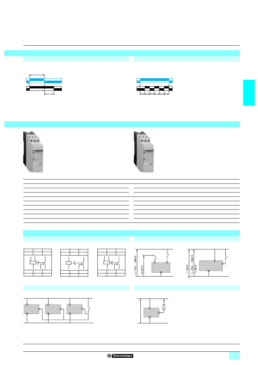
2/45
2
2
2
Function K
Function D
Delay on de-energisation (without auxiliary supply)
Symmetrical flashing, start with output in rest position
(1) If the device has been stored, de-energised, for more than a month, it must be energised for about 15 seconds in order to activate it. Subsequently, it only takes
80 ms to start the time delay.
2 If this time is not complied with, the relay remains energised indefinitely.
K
D
5
5
5
5
–
–
RE8 RB51BUTQ
–
–
–
RE8 RB11BUTQ
RE8 CL11BUTQ
RE8 RB31BUTQ
–
–
–
–
–
0.110
0.110
Schemes
Connection schemes
Recommended application schemes
RE8 TA, CL
RE8 RA
RE8 RB
RE8 TA, CL
RE8 RA
Control of several relays with a single external control contact
Connection of a
1
1
1
1 2-wire sensor
RE8 RA, RE8 PD
The external control contact C may be an electronic control device,
for example a 2-wire sensor. In this case A1-A2 =
1 24 V
and the control device can only control up to a maximum of 4 relays.
Leakage current (open state) If < 1 mA.
U
R
T
> 80 ms (1)
T
T
T
T
T
T
U
R
56
09
54
56
09
54
A1
15
B1
18
16
A2
18
15
B1
A2
A1
16
A1
15
Y1
18
16
A2
18
15
A2
A1
16
A1
15
B1
18
16
A2
18
15
B1
A2
A1
16
B1
A2
A1
A1
A2
Y1
start
Y1
A2
Y1
A2
Y1
A2
A1
A1
A1
C
Y1
–
+
A1
A2
If
Characteristics :
pages 2/42 and 2/43
Dimensions :
page 2/44
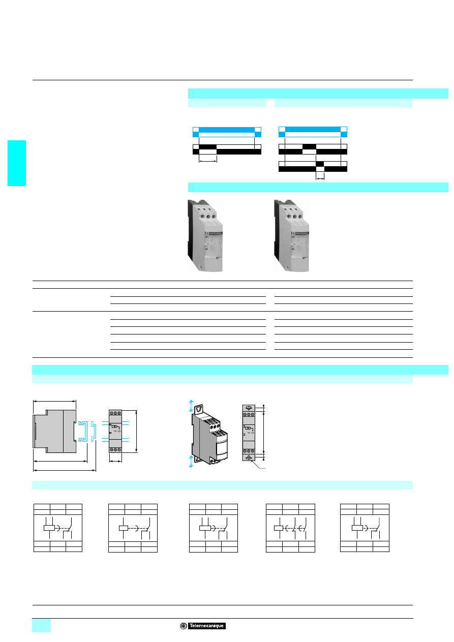
2/46
2
Functions,
references,
dimensions,
schemes
2
Zelio Time -
industrial timing relays
2
Single-function relays, optimum, relay output,
width 22.5 mm
Output 1 C/O contact
Single timing range
Function diagrams
Function H
Function W
Timing on energisation
On-delay after opening of control contact
Unit references
(Sold in packs of 10)
Functions
H
W
Voltages
13or 2 24 V
5
5
–
23110…240 V
5
–
5
2 380…415 V
–
–
–
Timing ranges
0.05 s…0.5 s
–
–
–
0.1 s…3 s
–
–
–
0.1 s…10 s
RE8 PE11BUTQ
RE8 PD11BTQ
RE8 PD11FUTQ
0.3 s…30 s
RE8 PE31BUTQ
RE8 PD31BTQ
RE8 PD31FUTQ
3 s…300 s
RE8 PE21BUTQ
RE8 PD21BTQ
RE8 PD21FUTQ
20 s…30 min
–
–
–
Weight (kg)
0.110
0.110
0.110
Dimensions, schemes
Dimensions
Rail mounting
Screw fixing
Connection schemes
(terminal blocks)
RE8 PE
RE8 PD
RE8 PT
RE8 YA
RE8 YG
U
R
T
T
U
C
R
56
09
68
56
09
68
89,5
80
82
22,5
78
Ø4
6
6
78
A1
15
B1
18
16
A2
18
15
16
B1
A2
A1
A1
15
Y1
18
16
A2
18
15
A2
A1
16
A1
15
B1
18
16
A2
18
15
16
B1
A2
A1
A1
15
25
28
16
A2
16
15
A2
A1
28
25
A1
15
B1
18
16
A2
18
15
B1
A2
A1
16
Characteristics :
pages 2/42 and 2/43
Schemes :
page 2/47
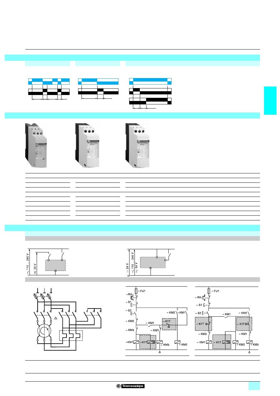
2/47
2
2
2
Function He
Function Qc
Function Qe
Pulse-on de-energisation
Star-delta timing
Star-delta timing
He
Qc
Qe
5
5
5
–
–
5
5
–
5
–
–
–
–
–
5
RE8 PT01BUTQ
–
–
–
–
–
–
–
–
–
–
RE8 YG11BUTQ
–
–
–
–
RE8 YG31BUTQ
RE8 YA32BTQ
RE8 YA32FUTQ
RE8 YA32QTQ
–
RE8 YG21BUTQ
–
–
–
–
–
–
–
–
0.110
0.110
0.110
0.110
0.110
Recommended application schemes
Pulse-on energisation relays
RE8 PE, RE8 PT
RE8 PD
Timing relays for star-delta starters
RE8 YG, RE8 YA
RE8 YG
RE8 YA
(1) K1T: RE8 YG
1111TQ
(1) K1T: RE8 YA32
11TQ
Note : Correct operation of the star-delta starter associated with the RE8 YG is only possible if the wiring scheme is strictly complied with.
U
R
> 80 ms
80 ms
T
> T
T
50 ms
U
R
T
80 ms
U
R1
R2
56
09
68
56
09
69
56
09
69
B1
A2
A1
A1
A2
Y1
+
start
– KM2
– KM3
– KM1
U1
V1
W1
U2
V2
W2
– Q1
L1
L2
L3
– Rth
Y
(1)
Y
A1
A2
A1
A2
A1
A2
A1
A2
16
15
L
(1)
(1)
Y
A1
A2
A1
A2
A1
A2
A1
A2
15
16
25
28
L
Characteristics :
pages 2/42 and 2/43
Dimensions :
page 2/46

2/48
2
Characteristics
2
Zelio Time - timing relays
2
Universal plug-in relays, 11-pin,
relay output, width 35 mm
Timing characteristics
Repeat accuracy
(with constant parameters)
Conforming to IEC 1812-1
± 0.5 %
Drift
Temperature
± 0.05 % / °C
Voltage
± 0.2 % / V
Full scale setting accuracy
Conforming to IEC 1812-1
± 10 % at 25 °C
Minimum duration of control
impulse
Typical
ms
30
Typical under load
ms
100
Maximum reset time
by de-energisation
Typical
ms
100
Immunity time
to microbreaks
Typical
ms
> 10
Supply characteristics
Multivoltage supply
Depending on version, see pages 2/50 and 2/52
Frequency
Hz
50/60
Operating range
85…110 % Un (85…120 Un for
2/1312 V )
On-load factor
100 %
Maximum power
consumption
Depending
on model
1 24 V
W
0.6
1 240 V
W
1.5
2 240 V
VA
32
Output characteristics
Output type
Relay, C/O contacts, AgNi (cadmium free)
Breaking capacity
2 2000 VA, 1380 W
Maximum breaking current
A
238, 13 8
Minimum breaking current
mA
10 /
1 5 V
Maximum switching voltage
V
2/13250
Electrical life
10
5
operations 8 A 250 V resistive
Mechanical life
5 x 10
6
operations
Dielectric strength
Conforming to IEC 1812-1
kV
2.5/1min/1 mA/50 Hz
Impulse voltage
Conforming to
IEC 664-1, IEC 1812-1
kV
5, wave 1.2/50 µs
Display characteristics
State indication by 1 LED
Green
Operating status indication
Pulsing: relay energised, no timing in progress
(except Di-D and Li-L)
Flashing: timing in progress
On steady: relay energised, no timing in progress
Input characteristics
Input type
V
Volt-free contact (no potential)
Control possible by 3-wire sensor with PNP output, maximum residual voltage: 0.4 V
whatever the supply voltage of the timer
References :
pages 2/50 and 2/52
Dimensions :
page 2/50
Schemes :
page 2/52
2/49
2
Characteristics
(continued)
2
Zelio Time - timing relays
2
Universal plug-in relays, 11-pin,
relay output, width 35 mm
General characteristics
Conforming to standards
IEC 1812-1, EN 50081-1/2, EN 50082-1/2, LV directives (73/23/EEC + 93/68/EEC
(
4 marking) + EMC (89/336/EEC + IEC 669-2-3)
Product certifications
c UR us, CSA, GL
Temperature limits
Operation
°C
- 20…+ 60
Storage
°C
- 30…+ 60
Creepage distance
and clearance
Conforming to IEC 60664-1
kV
4 kV/3
Degree of protection
conforming to IEC 529
Terminal block
IP 20
Enclosure
IP 40
Front panel
IP 50
Vibration resistance
Conforming to IEC 68-2-6
f = 10…55 Hz
A = 0.35 mm
Relative humidity
without condensation
Conforming to IEC 68-2-3
93 %
Electromagnetic
compatibility
Immunity to electrostatic
discharge,
conforming to IEC 1000-42
Level III (Air 8 kV/Contact 6 kV)
Immunity to electromagnetic
fields, conforming to
ENV 50140/204
(IEC 1000-4-3)
Level III 10 V/m : (80 MHz…1 GHz)
Immunity to fast transients
in bursts,
conforming to IEC 1000-4-4
Level III (direct 2 kV / capacitive connecting clip 1 kV)
Immunity to surges on the power
supply, conforming to
IEC 1000-4-5
Level III (common mode 2 kV / differential mode 1 kV)
Immunity to radio frequency
interference in common mode
conforming to
ENV 50141 (IEC 1000-4-6)
Level III (10 V rms : 0.15…80 MHz)
Immunity to voltage dips and
breaks, conforming to
IEC 1000-4-11
30 % / 10 ms
60 % / 100 ms
95 % / 5 s
Radiated and mains conducted
disturbance,
conforming to EN 55022
(EN 55011 Group 1)
Class B
Fixing
Plug-in socket
11-pin
Enclosure material
Self-extinguishing
References :
pages 2/50 and 2/52
Dimensions :
page 2/50
Schemes :
page 2/52
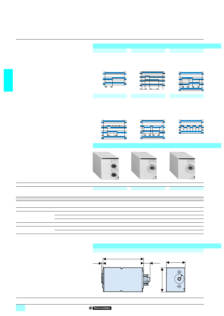
2/50
2
References,
dimensions,
schemes
2
Zelio Time - timing relays
2
Universal plug-in relays, 11-pin,
relay output, width 35 mm
Relay output, 2 C/O contacts
1 Multifunction, dual function or single function
1 Multi-range (7 switchable ranges)
1 Multivoltage
1 2 relay outputs: 8 A - 250 V (10 A UL)
1 Plug-in
1 State indication by 1 LED
1 Option of supplying a load in parallel
1 3-wire sensor control possible
Function diagrams
Function A
Function C
Function Ac
Delay on energisation
2 timed contacts or
2 timed contacts, 1 of which
convertible to instantaneous
Timing after opening of
control contact
2 timed contacts or
2 timed contacts, 1 of which
convertible to instantaneous
Timing after closing and
opening of control contact
2 timed contacts or
2 timed contacts, 1 of which
convertible to instantaneous
Function B
Function Ht
Function Di
Timing on impulse, one shot
2 timed contacts or
2 timed contacts, 1 of which
convertible to instantaneous
Timing on energisation wih
memory
2 timed contacts or
2 timed contacts, 1 of which
convertible to instantaneous
Symmetrical flashing, start
with output in operating
position
2 timed contacts or
2 timed contacts, 1 of which
convertible to instantaneous
References
Connection
Plug-in sub-base
5
5
5
Functions
Multifunction
Dual function
Single function
A - At - B - C - H - Ht - Di - D
Ac - Bw
A - At
C
Timing ranges
7 ranges
1 s - 10 s - 1 min - 10 min - 1 h - 10 h - 100 h
Relay output
2 timed contacts,
1 convertible to instantaneous
2 timed contacts
2 timed contacts
Rated current
8 A
8 A
8 A
Voltages
1324 V / 2324…240 V
RE 88 867 305
RE 88 867 415
RE 88 867 435
2/1312 V
–
–
–
2/1312…240 V
–
–
–
Weight (kg)
0.080
0.080
0.080
11-pin socket (1)
with connector
Mixed contact terminals (2)
RUZ C3M
RUZ C3M
RUZ C3M
Weight (kg)
0.054
0.054
0.054
(1) These products are sold in packs of 10
(2) The inputs are mixed with the relay’s supply terminals, with the outputs being located on the
opposite side of the socket.
Dimensions and connection schemes
Dimensions
U
R1/R2
R2 inst
T
U
C
R1/R2
∞
T
R2 inst.
U
C
R1/R2
T
T
R2 Inst.
U
C
R1/R2
∞
T
R2 Inst.
t1
R1/R2
C
U
t2
T = t1+t2
R2 Inst.
U
R1/R2
T T
R2 Inst.
56
11
80
56
11
81
56
11
81
45
3,5
12,5
74,5
35
Characteristics :
pages 2/48 and 2/49
Dimensions :
page 2/52
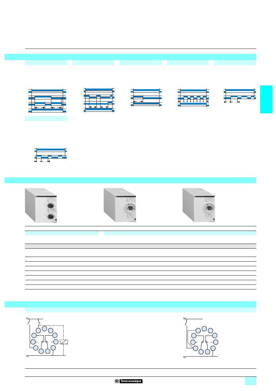
2/51
2
2
Function Bw
Function At
Function H
Function D
Function L
Pulse output (width
adjustable)
2 timed contacts or
2 timed contacts, 1 of which
convertible to instantaneous
Delay on energisation with
memory
2 timed contacts or
2 timed contacts, 1 of which
convertible to instantaneous
Timing on energisation
2 timed contacts or
2 timed contacts, 1 of which
convertible to instantaneous
Symmetrical flashing, start
with output in rest position
2 timed contacts or
2 timed contacts, 1 of which
convertible to instantaneous
Asymmetrical flashing,
Start with output in rest
position
2 timed contacts
Function Li
Asymmetrical flashing,
start with output in operating
position
2 timed contacts
5
5
5
Dual function
Multifunction
Multifunction
Li - L
A - At - B - C - H - Ht - Di - D - Ac - Bw
A - At - B - C - H - Ht - Di - D - Ac - Bw
1 s - 10 s - 1 min - 10 min - 1 h - 10 h - 100 h
2 timed contacts
2 timed contacts,
1 convertible to instantaneous
2 timed contacts,
1 convertible to instantaneous
8 A
8 A
8 A
RE 88 867 455
–
–
–
RE 88 867 300
–
–
–
RE 88 867 303
0.080
0.080
0.080
RUZ C3M
RUZ C3M
RUZ C3M
0.054
0.054
0.054
Connection schemes
All functions except L and Li
Functions L and Li
U
C
R
T
T
U
C
R1/R2
t1
t2
T = t1+t2
R2 Inst.
T
R1/R2
U
R2 Inst.
U
T T
R1/R2
R2 Inst.
T1
R1/R2
T2
U
T1
R1/R2
U
T2
56
11
80
56
118
2
56
118
2
U
4
R1
Y1
R2
+
–
5
6
7
8
9
10
11
1
2
3
U
(1)
4
R1
R2
+
–
5
6
7
8
9
10
11
1
2
3
Characteristics :
pages 2/48 and 2/49
Dimensions :
page 2/50
(1) Link between pins 2
and 5 for function L
only.
2/52
2
Characteristics
2
Zelio Time - timing relays
2
Universal plug-in relays, 8-pin,
relay output, width 35 mm
Timing characteristics
Repeat accuracy
(with constant parameters)
Conforming to IEC 1812-1
± 0.5 %
Drift
Temperature
± 0.05 % / °C
Voltage
± 0.2 % / V
Full scale setting accuracy
Conforming to IEC 1812-1
± 10 % at 25 °C
Minimum duration of control
impulse
Typical
ms
30
Typical under load
ms
100
Maximum reset time
by de-energisation
Typical
ms
100
Immunity time
to microbreaks
Typical
ms
> 10
Supply characteristics
Multivoltage supply
Depending on version, see pages 2/54 and 2/55
Frequency
Hz
50/60
Operating range
85…110 Un % (85…120 Un for
2/1312 V )
On-load factor
100 %
Maximum power
consumption
Depending on
model
1 24 V
W
0.6
1 240 V
W
1.5
2 240 V
VA
32
Output characteristics
Output type
Relay, 1 or 2 C/O contacts, AgNi (cadmium -free)
Breaking capacity
2 2000 VA, 1380 W
Maximum breaking current
A
238, 13 8
Minimum breaking current
mA
10/
1 5 V
Maximum switching voltage
V
2/13250
Electrical life
10
5
operations 8 A 250 V resistive
Mechanical life
5 x 10
6
operations
Dielectric strength
Conforming to IEC 1812-1
kV
2.5/1min/1 mA/50 Hz
Impulse voltage
Conforming to IEC 664-1,
IEC 1812-1
kV
5, wave 1.2/50 µs
Display characteristics
State indication by 1 LED
Green
Operating status indication
Pulsing: relay energised, no timing in progress
(except Di-D and Li-L)
Flashing: timing in progress
On steady: relay energised, no timing in progress
Input characteristics
Input type
V
Volt-free contact (no potential)
Control possible by 3-wire sensor with PNP output, maximum residual voltage: 0.4 V
whatever the supply voltage of the timer
References :
pages 2/54 and 2/55
Dimensions :
page 2/54
Schemes :
page 2/55

2/53
2
Characteristics
(continued)
2
Zelio Time - timing relays
2
Universal plug-in relays, 8-pin,
relay output, width 35 mm
General characteristics
Conforming to standards
IEC 1812-1, EN 50081-1/2, EN 50082-1/2, LV directives (73/23/EEC + 93/68/EEC
(
4 marking) + EMC (89/336/EEC + IEC 669-2-3)
Product certifications
c UR us, CSA, GL
Temperature limits
Operation
°C
- 20…+ 60
Storage
°C
- 30…+ 60
Creepage distance
and clearance
Conforming to IEC 60664-1
kV
4 kV/3
Degree of protection
conforming to IEC 529
Terminal block
IP 20
Enclosure
IP 40
Front panel
IP 50
Vibration resistance
f = 10…55 Hz
A = 0.35 mm
Relative humidity
without condensation
Conforming to IEC 68-2-3
93 %
Electromagnetic
compatibility
Immunity to electrostatic
discharge, conforming to
IEC 1000-42
Level III (Air 8 kV/Contact 6 kV)
Immunity to electromagnetic
fields, conforming to
ENV 50140/204
(IEC 1000-4-3)
Level III 10 V/m : (80 MHz…1 GHz)
Immunity to fast transients
in bursts
conforming to IEC 1000-4-4
Level III (direct 2 kV / capacitive connecting clip 1 kV)
Immunity to surges on the power
supply, conforming to
IEC 1000-4-5
Level III (common mode 2 kV / differential mode 1 kV)
Immunity to radio frequency
interference in common mode
conforming to ENV 50141
(IEC 1000-4-6)
Level III (10 V rms : 0.15…80 MHz)
Immunity to voltage dips and
breaks conforming to
IEC 1000-4-11
30 % / 10 ms
60 % / 100 ms >
95 % / 5 s
Radiated and mains conducted
disturbance
conforming to EN 55022
(EN 55011 Group 1)
Class B
Fixing
Plug-in socket
8-pin
Enclosure material
Self-extinguishing
References :
pages 2/54 and 2/55
Dimensions :
page 2/54
Schemes :
page 2/55
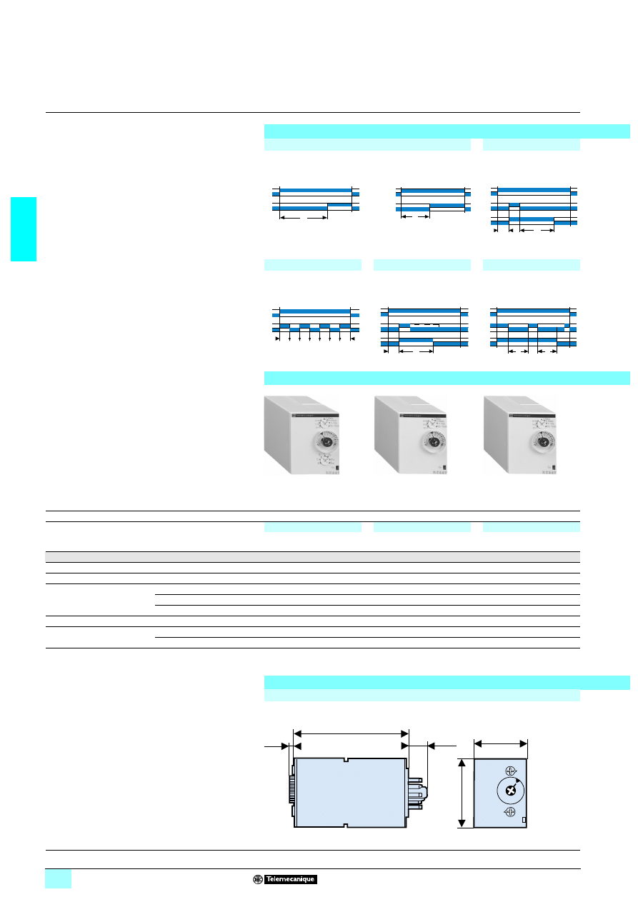
2/54
2
References,
dimensions,
schemes
2
Zelio Time - timing relays
2
Universal plug-in relays, 8-pin,
relay output, width 35 mm
Relay output, 1 or 2 C/O contacts
1 Multifunction of single function
1 Multi-range (7 switchable ranges)
1 Multivoltage
1 1 or 2 relay outputs: 8 A - 250 V (10 A UL)
1 Plug-in
1 State indication by 1 LED
1 Option of supplying a load in parallel
1 3-wire sensor control option
Function diagrams
Function A
Function C
Delay on energisation
1 contact
2 timed contacts
Timing after opening of
control contact
1 timed contact
Function Di
Function B
Function Ht
Symmetrical flashing, start
with output in operating
position
Timing on impulse, one shot
Timing on energisation with
memory
References
Connection
Plug-in sub-base
5
5
5
Functions
Multifunction
Single function
Single function
A - At - B - C - H - Ht - Di - D
Ac - Bw
A
C
Timing ranges
7 ranges
1 s - 10 s - 1 min - 10 min - 1 h - 10 h - 100 h
Relay output
1 timed contact
2 timed contacts
1 timed contact
Rated current
8 A
8 A
8 A
Voltages
1324 V / 2324…240 V
RE 88 867 105
RE 88 867 215
RE 88 867 135
2/1312 V
–
–
–
2/1312…240 V
–
–
–
Weight (kg)
0.080
0.080
0.080
8-pin socket (1)
with connector
Mixed contact terminals (2)
RUZ C2M
RUZ C2M
RUZ C2M
Weight (kg)
0.054
0.054
0.054
(1) These products are sold in packs of 10.
(2) The inputs are mixed with the relay’s supply terminals, with the outputs being located on the
opposite side of the socket.
Dimensions and connection schemes
Dimensions
U
R
T
U
R1/R2
T
U
C
R
∞
T
U
R
T T
U
C
R
∞
T
t1
R
C
U
t2
T = t1+t2
56
11
77
56
11
78
56
11
78
45
3,5
12,5
74,5
35
Characteristics :
pages 2/52 and 2/53
Schemes :
page 2/55
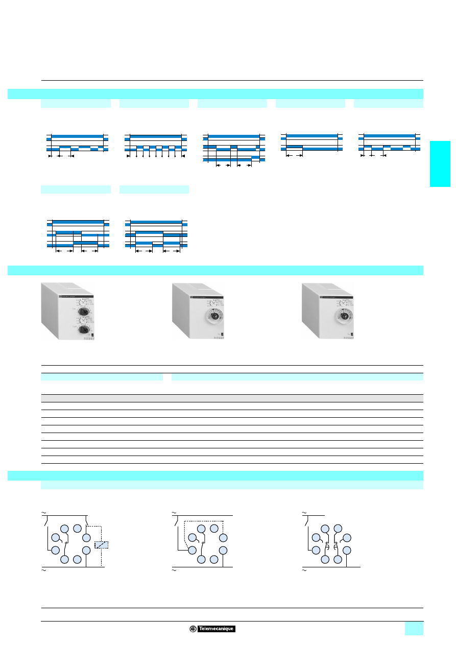
2/55
2
2
2
Function L
Function D
Function At
Function H
Function Li
Asymmetrical flashing,
start with output in rest
position
Symmetrical flashing,
start with output in rest
position
Delay on energisation
with memory
Timing on energisation
Asymmetrical flashing,
start with output in operating
position
Function Ac
Function Bw
Timing after closing and
opening of control contact
Pulse output (width
adjustable)
5
5
5
Dual function
Multifunction
Multifunction
Li - L
A - At - B - C - H - Ht - Di - D - Ac - Bw
A - At - B - C - H - Ht - Di - D - Ac - Bw
1 s - 10 s - 1 min - 10 min - 1 h - 10 h - 100 h
1 timed contact
1 timed contact
1 timed contact
8 A
8 A
8 A
RE 88 867 155
–
–
–
RE 88 867 100
–
–
–
RE 88 867 103
0.080
0.080
0.080
RUZ C2M
RUZ C2M
RUZ C2M
0.054
0.054
0.054
Connection schemes
Timing relays with 1 relay output
All functions except L and Li
Functions L and Li
(1) Link between pins 2 and 6 for function L only.
Timing relays with 2 relay outputs
Function A
T1
R
T2
U
U
T T
R
U
C
R
t1
t2
T = t1+t2
T
R
U
T1
R
U
T2
U
C
R
T
T
U
C
R
T
T
56
11
79
56
11
78
56
11
78
U
4
R
+
–
5
6
7
8
1
2
3
Y
U
(1)
4
R
+
–
5
6
7
8
1
2
3
U
4
R1
R2
+
–
5
6
7
8
1
2
3
Characteristics :
pages 2/52 and 2/53
Dimensions :
page 2/54
2/56
2
Characteristics
2
Zelio Time - timing relays
2
Miniature plug-in relays, relay output
Timing characteristics
Repeat accuracy (with constant parameters)
± 0.5 %
Full scale setting accuracy
Conforming to IEC/EN 61812-1
10 % at 25 °C
Temperature drift
0.05 %/ °C
Maximum reset time
by de-energisation
During time delay period
ms
50
After time delay period
ms
250
Immunity to microbreaks
ms
≤ 5
Voltage drift
± 0.2 % / V
Output characteristics
Output type
Relay
2 and 4 cadmium-free C/O contacts
Rated current
A
2 5
Rated insulation voltage
V
2 250
Maximum breaking capacity (resistive)
A
4 x 5
Maximum permissible current
A
10 < 0.01 s
Minimum breaking current
mA
100
Electrical life at I max
4
4
4
4 250 V resistive
10
5
operating cycles
Mechanical life
10
7
operations
Dielectric strength
To IEC/EN 61812-1 and 60601-1
2 kV at 1 mA for 1 min at 50 Hz
General characteristics
Conforming to standards
IEC/EN 61812-1, 60601-1, 60601-2, EN 50081-2, 61000-6-2,
LV (73/23/EEC + 93/68/EEC) + EMC (89/336/EEC) directives
Product certifications
UL-cUL
State indication by LED
Output in operation
Red LED
Power on
Yellow LED
Permissible voltage variation
1 12 V
± 10 %
1 24 V
± 10 %
2324 V
± 15 %
23120 V
± 15 %
23230 V
± 15 %
Frequency
Hz
50/60 ± 1
Maximum power consumption
1 12 V
W
1.5
3
1 24 V
W
1.2
2324 V
VA
1.7
3
23120 V
VA
2.6
3
23230 V
VA
3
Temperature limits
Operation
°C
- 20…+ 60
Storage
°C
- 40…+ 70
Insulation voltage
To standard VDE 0010
IEC 255 Group C
V
2/1 250
Degree of protection
Conforming to IEC 60529
IP 50
Overvoltage protection
joules
2
Fixing
Base-mounted
On socket
Vibration resistance
Conforming to IEC 60068-2-6,
10 to 55 Hz
a = 0.35 mm
Relative humidity
Conforming to IEC 60068-2-3
without condensation
95 % max
Immunity to electromagnetic interference (EMC)
(application class 2 conforming to EN 61812-1/A11)
Electrostatic discharge
Conforming to IEC/EN 61000-4-2
Level 3 (Air 8 kV contact, 6 kV)
Electromagnetic fields
Conforming to IEC/EN 61000-4-3
Level 3 (10 V/m)
Fast transients
Conforming to IEC/EN 61000-4-4
Level 3 (2 kV)
Shock waves
Conforming to IEC/EN 61000-4-5
Level 3 (2 kV)
Radio frequencies
in common mode
Conforming to IEC/EN 61000-4-6
Level 3 (10 V rms from 0.15 MHz to 80 MHz)
Voltage dips and breaks
Conforming to IEC/EN 61000-4-11
30 %/10 ms, 60 %/100 ms and 1 s, > 95 %/5 s
Radiated and conducted
emissions
Conforming to EN 55022
(EN 55011 group 1)
Class B
Creepage distance
and clearance
Conforming to IEC 60664-1
kV
4, in category 3
Internal schemes
Relay with 4 C/O contacts
Relay with 2 C/O contacts
- 13
9
5
1
+ 14
6
10
2
11
7
3
12
8
4
- 13
9
5
1
+ 14
8
12
4
References :
page 2/57
Dimensions :
page 2/57
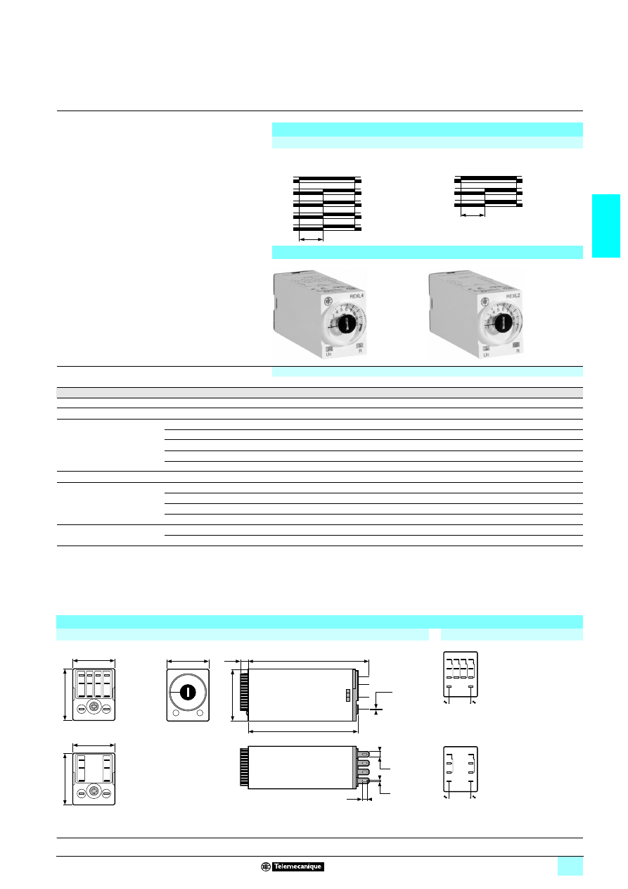
2/57
2
Functions,
references,
dimensions
2
Zelio Time - timing relays
2
Miniature plug-in relays, relay output
Relay output, 2 and 4 C/O contacts
1 Miniature and plug-in (21 x 27 mm)
1 Function A : on-delay
1 7 timing ranges: 0.1 s to 100 h
1 Excellent immunity to interference
1 Power on and relay energised indication by 2 LEDs
Function diagrams
Function A
Delay on energisation
4 timed C/O contacts
2 timed C/O contacts
References
Functions
Single function
A
Timing ranges
7 switchable ranges
0.1 s…1 s - 1 s…10 s - 0.1 min…1 min - 1 min…10 min - 0.1 h…1 h - 1 h…10 h - 10 h…100 h
Relay output
4 timed C/O contacts
2 timed C/O contacts
Rated current
235 A
235 A
Voltages
1312 V
RE XL4TMJD
RE XL2TMJD
1324 V (1)
RE XL4TMBD
RE XL2TMBD
2324 V 50/60 Hz (1)
RE XL4TMB7
RE XL2TMB7
23120 V 50/60 Hz
RE XL4TMF7
RE XL2TMF7
23230 V 50/60 Hz
RE XL4TMP7
RE XL2TMP7
Weight (kg)
0.050
0.050
Sockets (2) with
mixed contact terminals (3)
With screw clamp terminals
RXZ E2M114 (5)
RXZ E2M114 (5)
Weight (kg)
0.048
0.048
With connector
RXZ E2M114M (5)
RXZ E2M114M (5)
Weight (kg)
0.056
0.056
Sockets (2) with
separate contact terminals (4)
With connector
RXZ E2S114M (6)
RXZ E2S108M (6)
Weight (kg)
0.058
0.070
(1) For
6 48 V supply, additional resistor 560 Ω 2 W / 6424 V.
For
3448 V supply, additional resistor 390 Ω 4 W / 3424 V.
(2) These products are sold in lots of 10.
(3) The inputs are mixed with the relay’s supply terminals, with the outputs being located on the
opposite side of the socket.
(4) The inputs and outputs are separated from the relay supply terminals.
(5) Thermal current Ith: 10 A
(6) Thermal current Ith: 12 A
Dimensions and terminal referencing
Dimensions
Terminal referencing
RE XL4TM
33
33
33
33
13-14
1-5-9
4-8-12
T
2-6-10
3-7-11
13-14
1-5-9
4-8-12
T
53
25
35
53
25
36
27
21
27
21
RE XL2TM
33
33
33
33
R
Un
21
65,5
3,5
27
59,5
0,55
2,8
0,3
1,2
1
5
9
13
(-)
2
6
10
3
7
11
4
8
12
14
(+)
1
5
9
13
(-)
4
8
12
14
(+)
Characteristics :
page 2/56
Schemes :
page 2/56
2/58
2
Presentation
2
Zelio Time - timing relays
2
Electronic relays, relay output, 48 x 48 housing
The range of RE 48A timing relays, in 48 x 48 housing, is specially designed for
integration in machines and equipment. It is suitable for applications requiring
frequent modification or adjustment of the timing cycles.
RE 48A relays have the following characteristics:
1 All references are multivoltage 24 to 240 V 4 and 5 and are therefore suitable
for the majority of applications while at the same time reducing the number of
products to be stocked.
1 The timing ranges covered are from 0.02 s to 300 h.
1 These timing relays can be panel-mounted using the spring clip supplied as
standard, or DIN rail-mounted using standard sockets.
1 Two LED's on the front face provide immediate indication of the timing status:
2 power ON,
2 output relay state,
2 timing in progress.
The size of the knob and clear indication of the timing scale allow easy adjustment,
eliminating any errors during parameter setting.
In addition, in applications where only the timing cycle value is left freely accessible
to users, a protective cover can be used to block access to the other settings.
This range is comprises 4 references:
(1) This relay features control inputs which provide a wider choice of timing modes:
Start Input to control the start of timing,
Gate Input to suspend the timing in progress without cancelling it,
Reset Input to reset timing to its initial state during the cycle.
Presentation
Reference
Description
RE 48A TM12MW
Single function
7 On-delay
7 two relay outputs
RE 48A CV12MW
Dual function
7 asymmetrical flasher
7 two relay outputs
RE 48A MH13MW
Multifunction
7 On-delay and pulse-on energisation
7 two relay outputs, of which one selectable and
instantaneous
RE 48A ML12MW (1)
Multifunction
7 On-delay
7 timing on impulse
7 Off-delay
7 symmetrical flasher
Characteristics :
pages 2/60 and 2/61
Function diagrams :
page 2/62
References :
pages 2/63 and 2/64
Dimensions :
pages 2/63 and 2/64
Mounting :
page 2/65
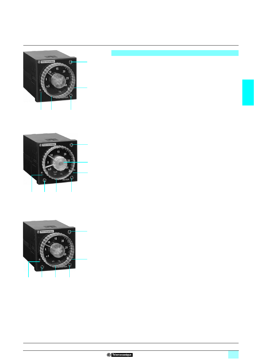
2/59
2
Description
2
Zelio Time - timing relays
2
Electronic relays, relay output, 48 x 48 housing
Description
RE 48A TM12 MW timing relays have the following on the front face :
1
A time base selector knob (12 and 30)
2
A time unit selector knob (x 0.1 s, x 1 s, x 10 s, x 1 min, x 10 min, x 1 h, x 10 h)
3
A timing adjustment knob
4
A yellow LED, indicating the status of the output relay
5
A green LED, indicating power ON (flashing during the timing period).
RE 48A CV12 MW timing relays have the following on the front face :
1
A time base selector knob (12 and 30)
2
Two time unit selector knobs (x 0.1 s, x 1 s, x 10 s, x 1 min, x 10 min, x 1 h,
x 10 h)
3
An orange button for setting the pulse time
4
A white button for setting the pause time
5
A yellow LED, indicating the status of the output relay
6
A green LED, indicating power ON (flashing during the timing period).
RE 48A M
616 MW timing relays have the following on the front face :
1
A time base selector knob (12 and 30)
2
A time unit selector knob (x 0.1 s, x 1 s, x 10 s, x 1 min, x 10 min, x 1 h, x 10 h)
3
A function selector knob:
A, B, C, Di for RE 48A ML12 MW
A1, A2, H1, H2 for RE 48A MH13 MW
4
A timing adjustment knob
5
A yellow LED, indicating the status of the output relay
6
A green LED, indicating power ON (flashing during the timing period).
1
5
4
3
2
52
19
34
1
6
3
2
5
2
4
52
19
35
1
4
5
6
2
3
52
19
36
Characteristics :
pages 2/60 and 2/61
Function diagrams :
page 2/62
References :
pages 2/63 and 2/64
Dimensions :
pages 2/63 and 2/64
Mounting :
page 2/65
2/60
2
Characteristics
2
Zelio Time - timing relays
2
Electronic relays, relay output, 48 x 48 housing
General characteristics
Conforming to standards
IEC 61812-1, EN 50081-1/2, EN 50082-1/2, LV directives (73/23/EEC + 93/68/EEC
1
1
1
13marking) + EMC directive (89/336/EEC + IEC 60669-2-3)
Approvals
UL, cULus, C-Tick, CSA, GL
Ambient air temperature
around the device
Storage
°C
- 40…+ 70
Operation
°C
- 20…+ 50
Degree of protection
conforming to IEC 60529
Housing
IP 40
Front face
IP 50
Vibration resistance
Conforming to IEC 60068-2-6
f = 10…55 Hz
A = 0.35 mm
Relative humidity
without condensation
Conforming to IEC 60068-2-3
93 %
Electromagnetic compatibility Immunity to
electrostatic discharge,
conforming to IEC/EN 61000-4-2
Level III (Air 8 kV/Contact 6 kV)
Immunity to
electromagnetic fields
conforming to IEC/EN 61000-4-3
Level III (10 V/m: 26 MHz…1 GHz)
Immunity to
fast transients in bursts,
conforming to IEC/EN 61000-4-4
Level IV (direct 4kV / capacitive connecting clip 2 kV)
Immunity to
surges on the power supplies,
conforming to IEC 61000-4-5
Level III (common mode 2 kV / differential mode 1 kV)
Immunity to radio frequency
interference in common mode,
conforming to IEC/EN 61000-4-6
Level III (10 V rms: 0.15…80 MHz)
Immunity to
voltage dips and breaks,
conforming to IEC/EN 61000-4-11
30 % / 10 ms
60 % / 100 ms
95 % / 5 s
60 % / 1 s
Radiated and mains
conducted disturbance,
conforming to EN 55022
(EN 55011 Group 1)
Class B (0.15...30 MHz)
Fixing
Panel-mounting
Using mounting system (supplied with the product)
Base-mounted
With socket
Connection
By socket or connector
Housing material
Self-extinguishing
Input characteristics
Type of input
by volt-free contact
Start: starts the function (only for functions A, B, C and Di on RE 48A ML12 MW)
Gate: stops timing in progress
Reset: resets the relay, output to OFF
Output characteristics
Output type
Relay with 2 timed changeover contacts (except RE 48A MH13 MW: relay with
1 timed changeover contact and 1 instantaneous changeover contact)
Contact type
AgNi (cadmium-free)
Breaking capacity
VA
2 1250
Maximum breaking current
A
2 5 for 250 V
Minimum breaking current
mA
100/
1 12 V
Maximum switching voltage
V
2/1 250
Electrical durability
10
5
operations
Mechanical durability
30 x 10
6
operations
Dielectric strength
Conforming to IEC 61812-1
kV
1/1min
Electric shock resistance
Conforming to
IEC 60664-1, IEC 61812-1
kV
4, category 3
Rated operational voltage
2 AC-12
Ue = 240 V and Ie = 5 A
2 AC-15
Ue = 240 V and Ie = 1.5 A
1 DC-13
Ue = 30 V and Ie = 2 A
Presentation, description :
pages 2/58 and 2/59
Function diagrams :
page 2/62
References :
pages 2/63 and 2/64
Dimensions :
pages 2/63 and 2/64
Mounting :
page 2/65
2/61
2
Characteristics
2
Zelio Time - timing relays
2
Electronic relays, relay output, 48 x 48 housing
Supply characteristics
Supply voltage
V
2/1324…240
Frequency
Hz
50/60
Operating range
2 - 15 %...+ 10 %
1 - 10 %...+ 10 %
On-load factor
100 %
Maximum
power consumption
Depending
on model
1 24 V
W
0.5
2 24 V
VA
1.1
1 240 V
W
1.7
2 240 V
VA
4.8
Timing characteristics
Selectable timing ranges
by selector switch on front face
s
Time unit
Time scale
0.02…1.2
x 0.1 s
12
0.05…3
x 0.1 s
30
0.2…12
x 1 s
12
0.5…30
x 1 s
30
2…120
x 10 s
12
5…300
x 10 s
30
min
0.2…12
x 1 min
12
0.5…30
x 1 min
30
2…120
x 10 min
12
5…300
x 10 min
30
h
0.2…12
x 1 h
12
0.5…30
x 1 h
30
2…120
x 10 h
12
5…300
x 10 h
30
Repeat accuracy
(with constant parameters)
Conforming to IEC 61812-1
± 0.2 % of the maximum setting value
Drift
conforming to IEC 61812-1
Temperature
± 0.02 %/°C of the maximum setting value
Humidity
± 0.05 %/%HR of the maximum setting value
Voltage
2/1 24...48 V: ± 1 %/V of the maximum setting value
2/1 48...240 V: ± 0.2 %/V of the maximum setting value
Setting accuracy at full scale Conforming to IEC 61812-1
± 5 % at 25 °C
Minimum control pulse
duration on the
Gate/Start/Reset input
Typical
ms
20
Minimum reset time by de-energisation
ms
25
Delay on pick-up
ms
55
Immunity to microbreaks
ms
< 10
Display characteristics
State indication
Green LED
Flashing: timer energised, timing in progress
On steady: timer energised, relay energised, no timing in progress
Yellow LED
On: output relay ON
Off: output relay OFF
Presentation, description :
pages 2/58 and 2/59
Function diagrams :
page 2/62
References :
pages 2/63 and 2/64
Dimensions :
pages 2/63 and 2/64
Mounting :
page 2/65
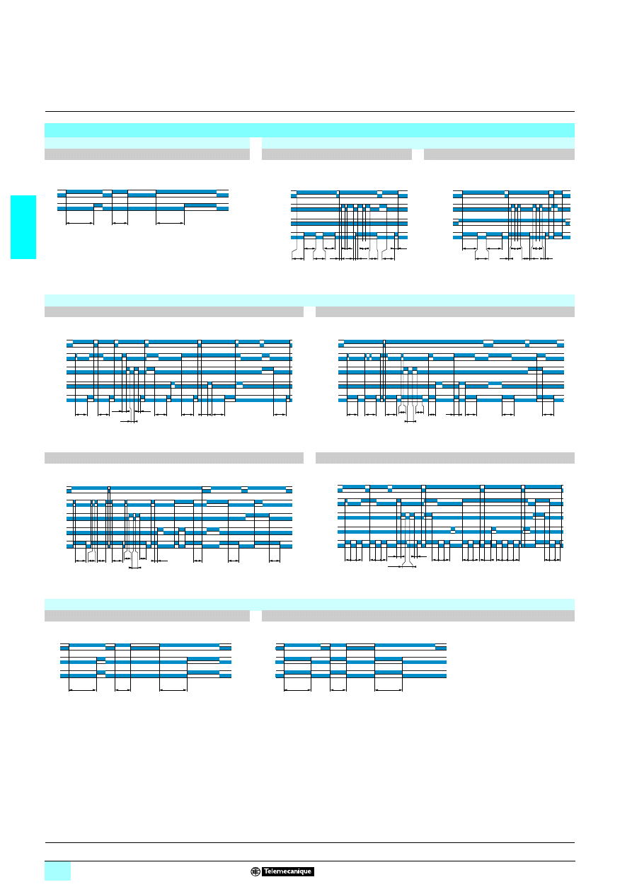
2/62
2
Functions
2
Zelio Time - timing relays
2
Electronic relays, relay output, 48 x 48 housing
Function diagrams
RE 48A TM12 MW
RE 48A CV12 MW
Function A
Function L
Function Li
Delay on energisation
Asymmetrical flashing, start with output in
rest position
Asymmetrical flashing, start with output in
operating position
RE 48A ML12 MW
Function A
Function B
Delay on energisation
Timing on impulse, one shot
Function C
Function Di
Timing after opening of control contact
Symmetrical flashing, start with output in operating position
RE 48A MH13 MW
Functions A1, A2
Functions H1, H2
Delay on energisation
Pulse-on energisation
Note : If A1 or H1 are selected, only R2 is timed, R1 is instantaneous
T
T
Un
R
t3
ta tc
t2
tb
t1
Un
Gate
2 - 6
Nor / Inv
Toff
Ton
Toff = t1+t2+t3 Ton = ta+tb+tc
R
Toff
Toff
Ton
t3 ta
t2
tb
t1
t1
Un
Gate
2 - 6
Nor / Inv
Ton
Ton = t1+t2+t3 Toff = ta+tb+tc
R
Toff
Ton
T
T
t2
T = t1 + t2 + t3
t1
t3
T
T
T
T
t
Un
Start
Gate
Reset
R
T
T
T
t1
t3
t2
T = t1 + t2 + t3
T
T
T
Un
Start
Gate
Reset
R
T
T
t1
t3
t2
T = t1 + t2 + t3
T
T
Un
Start
Gate
Reset
Output
T T T
T T T
t1t2
T = t1 + t2
t1
t2
T T T
T T T
T T T
T T T T
T
Un
Start
Gate
Reset
Output
T
T
Un
R2
R1
T
T
Un
R2
R1
Presentation, description :
pages 2/58 and 2/59
Characteristics :
pages 2/60 and 2/61
References :
pages 2/63 and 2/64
Dimensions :
pages 2/63 and 2/64
Mounting :
page 2/65
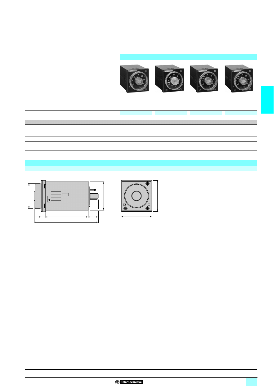
2/63
2
References,
dimensions
2
Zelio Time - timing relays
2
Electronic relays, relay output, 48 x 48 housing
References
Plug-in
8-pin
11-pin
11-pin
8-pin
Functions
Single function
Dual function
Multifunction
Multifunction
A
L, Li
A, B, C, Di
A1, A2, H1, H2
Timing ranges
1.2 s, 3 s, 12 s, 30 s, 120 s, 300 s, 12 min, 30 min, 120 min, 300 min, 12 h, 30 h, 120 h, 300 h
Relay output
2 C/O timed contacts
2 C/O timed contacts
2 C/O timed contacts
1 C/O timed contact
1 C/O instantaneous
contact
Rated current
2 x 5 A
2 x 5 A
2 x 5 A
2 x 5 A
Voltages
1/2324…240 V
RE 48A TM12 MW
RE 48A CV12 MW
RE 48A ML12 MW
RE 48A MH13 MW
Weight (kg)
0.140
0.140
0.140
0.140
Dimensions
RE 48A
22
22
22
22 12222 MW
48
44,4
Ø39
6,8
64,5
15,5
48
96,8
Presentation, description :
pages 2/58 and 2/59
Characteristics :
pages 2/60 and 2/61
Mounting :
page 2/65
52
19
38
521
93
7
521
93
9
52
19
39
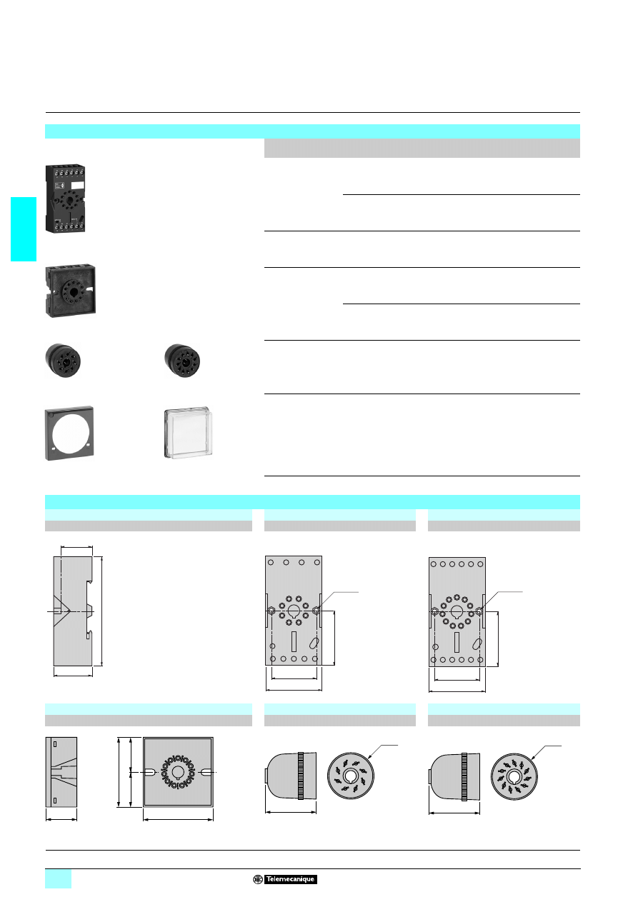
2/64
2
References,
dimensions
2
Zelio Time - timing relays
2
Electronic relays, relay output, 48 x 48 housing
References
Description
Number
of pins
For
use with
Sold in
lot of
Unit
reference
Weight
kg
IP 20 sockets
with screw terminal
connections and
mixed contact
terminals (1)
8
RE 48A TM12 MW,
RE 48A MH13 MW
10
RUZ C2M
0.054
11
RE 48A CV12 MW,
RE 48A ML12 MW
10
RUZ C3M
0.054
IP 20 socket
with screw terminal
connections on rear
face
11
RE 48A CV12 MW,
RE 48A ML12 MW
1
RE 48A SOC11 AR
–
IP 20 solder
connectors
8
RE 48A TM12 MW,
RE 48A MH13 MW
1
RE 48A SOC8 SOLD
–
11
RE 48A CV12 MW,
RE 48A ML12 MW
1
RE 48A SOC11 SOLD
–
Setting protection
cover
–
RE 48A TM12 MW
RE 48A CV12 MW
RE 48A ML12 MW
RE 48A MH13 MW
1
RE 48A SET COV
–
IP 64 protective cover –
RE 48A TM12 MW
RE 48A CV12 MW
RE 48A ML12 MW
RE 48A MH13 MW
1
RE 48A IP COV
–
(1) The inputs are mixed with the relay’s supply terminals, with the outputs being located on the
opposite side of the socket.
RUZ C3M
RE 48A SOC11 AR
RE 48A SOC8 SOLD
RE 48ASOC11 SOLD
RE 48A SET COV
RE 48A IP COV
Dimensions
Common side view
8-pin socket
11-pin socket
RUZ C
3333M
RUZ C2M
RUZ C3M
11-pin socket
8-pin connector
11-pin connector
RE 48A SOC11 AR
RE 48A SOC8 SOLD
RE 48A SOC11 SOLD
75
27
22
38
30
24
6
2
7
A2
7
A1
2
11
1
21
8
A2
7
INPUT A2
INPUT A1
22
5
12
4
1
4
2
3
8
5
7
6
14
3
2xØ3,1
37
38
37
30
A2
10
A2
10
31
11
21
6
11
1
A1
2
34
9
32
8
24
7
22
5
14
3
12
4
2
10
1
6
2
5
3
4
11
10
7
9
8
INPUT A2
INPUT A1
2xØ3,1
=
=
46
46
20
Ø30
34
Ø30
34
Presentation, description :
pages 2/58 and 2/59
Function diagrams :
page 2/62
Characteristics :
pages 2/60 and 2/61
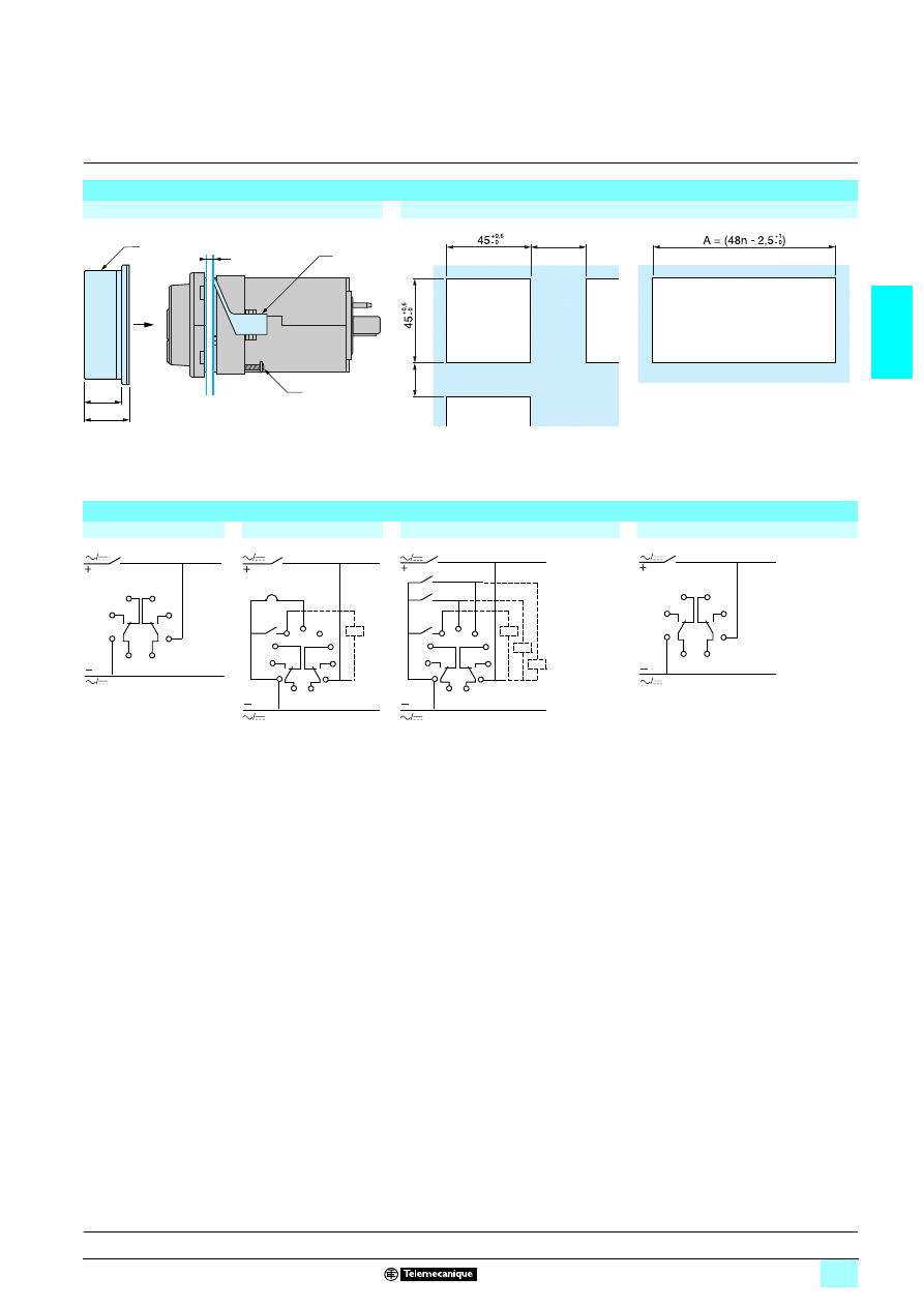
2/65
2
Mounting,
schemes
2
Zelio Time - timing relays
2
Electronic relays, relay output, 48 x 48 housing
Mounting
Cover positioning and mounting
Panel cut-out
e : panel thickness
(1) IP 64 protective cover: RE 48A IP COV
(2) Panel mounting frame
(3) Locating screw
n : Number of devices mounted side-by-side
Connection schemes
RE 48A TM12 MW
RE 48A CV12 MW
RE 48A ML12 MW
RE 48A MH13 MW
e
(2)
(3)
17
20
(1)
15
30
1
U
R
2
3
4 5
8
7
6
6 7
5
8
4
9
3
11
1
10
2
U
R
Gate
6 7
5
8
4
9
3
11
1
10
2
U
R
Reset
Start
Gate
1
U
R1
R2
2
3
4 5
8
7
6
Presentation, description :
pages 2/58 and 2/59
Function diagrams :
page 2/62
Characteristics :
pages 2/60 and 2/61
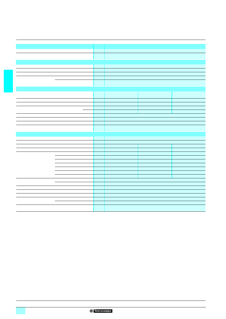
2/66
2
Characteristics
2
Zelio Time - timing relays
2
Panel-mounted, plug-in, universal relays
Display characteristics
Number of digits
4
Digit height
mm
8
Timing characteristics
Repeat accuracy (with constant parameters)
± 0.03 % ± 20 ms
Full scale setting accuracy
± 0.03 % ± 20 ms
Minimum duration of control impulse
ms
50
Maximum reset time by
de-energisation
During time delay period
ms
50
After time delay period
ms
50
Output characteristics
Relay type
RE 88 857 40
32
32
32
32
RE 88 857 10
3333
RE 88 857 00
3333
RE 88 857 30
32
32
32
32
Rated current
A
235, 135
238, 138
238, 138
Maximum switching voltage
V
23250, 1330
23250, 1330
23250, 1330
Maximum breaking capacity
on resistive load
2
VA
1250
2000
2000
1
W
120
190
190
Maximum permissible current
A
15 < 0.01 s
Minimum current
mA
100
Electrical life at I
max,
4
4
4
4 250 V resistive
10
5
cycles
Mechanical life
5 million operating cycles
General characteristics
Conforming to standards
IEC 255, VDE 0435-2021
Product certifications
c UR us, CSA
Permissible voltage variation
- 15…+ 10 %
- 15…+ 10 %
- 15…+ 10 %
Immunity to microbreaks
s
< 0.03
< 0.03
< 0.03
Maximum power
consumption
1312 V
W
–
0.5
0.
1324 V
W
0.5
0.5
0.5
1348 V
W
–
1
1
2324 V
VA
1
1
1
2348 V
VA
–
2
2
23110 V
VA
3.5
3.5
3.5
23220 V
VA
11
11
11
Temperature limits
Operation
°C
- 10…+ 60
Storage
°C
- 30…+ 70
Front panel degree of protection
IP 65
Insulation
Conforming to standard VDE 0110 and IEC 225 Group C
Protection class
Conforming to UTE C 20010, IEC 529, DIN 40050
Fixing
Panel-mounted
By clip
Base-mounted
On socket
Material
Self-extinguishing UL 94 grade Vo
Functions :
page 2/68
Schemes :
page 2/67
References :
page 2/69
Dimensions :
page 2/69
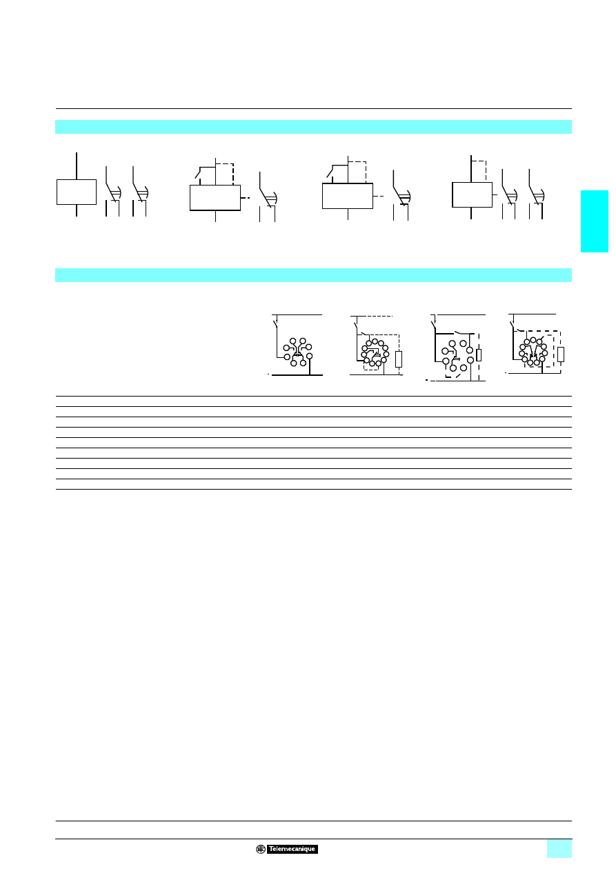
2/67
2
Schemes
2
Zelio Time - timing relays
2
Panel-mounted, plug-in, universal relays
Internal schemes
Relay RE 88 857 40
3333
Relay RE 88 857 10
3333
Relay RE 88 857 00
3333
Relay RE 88 857 30
3333
Terminal referencing
(1) Another load may be connected.
Relay
RE 88 57 40
32
32
32
32
RE 88 857 10
32
32
32
32
RE 88 857 00
32
32
32
32
RE 88 557 30
32
32
32
32
Supply 2-10
–
5
–
5
Supply 2-7
5
–
5
–
Link 2-11 :
1 12 V or 2/1 24 V
–
5
–
–
Link 2-7 :
1 12 V or 2/1 24 V
–
–
–
5
Link 2-8 :
1 12 V or 2/1 24 V
–
–
5
–
2-5 or 2-6 control or reset contact
–
5
5
5
1-3-4 timed output contact
5
5
5
5
8-5-6 timed output contact
5
–
–
–
8-9-11 timed or instantaneous output contact
–
–
–
5
7
2
1
3 4
8
6
5
1
10
3 4
5
2
-
+
11
1
7
3 4
6
2
-
+
8
1
10
3 4
11
9
8
2
-
+
7
6
7
8
1
2
3
4
5
~
+
U
~
+
~
9
U
6
7
8
10
11
1
2
3
4
5
-
~
Start
(1)
6
7
8
1
2
3
4
5
~
+
U
~
Start
(1)
9
U
6 7
8
10
11
1
2
3
4
5
~
+
~
(1)
Reset
Characteristics :
page 2/66
Functions
page 2/68
References :
page 2/69
Dimensions :
page 2/69
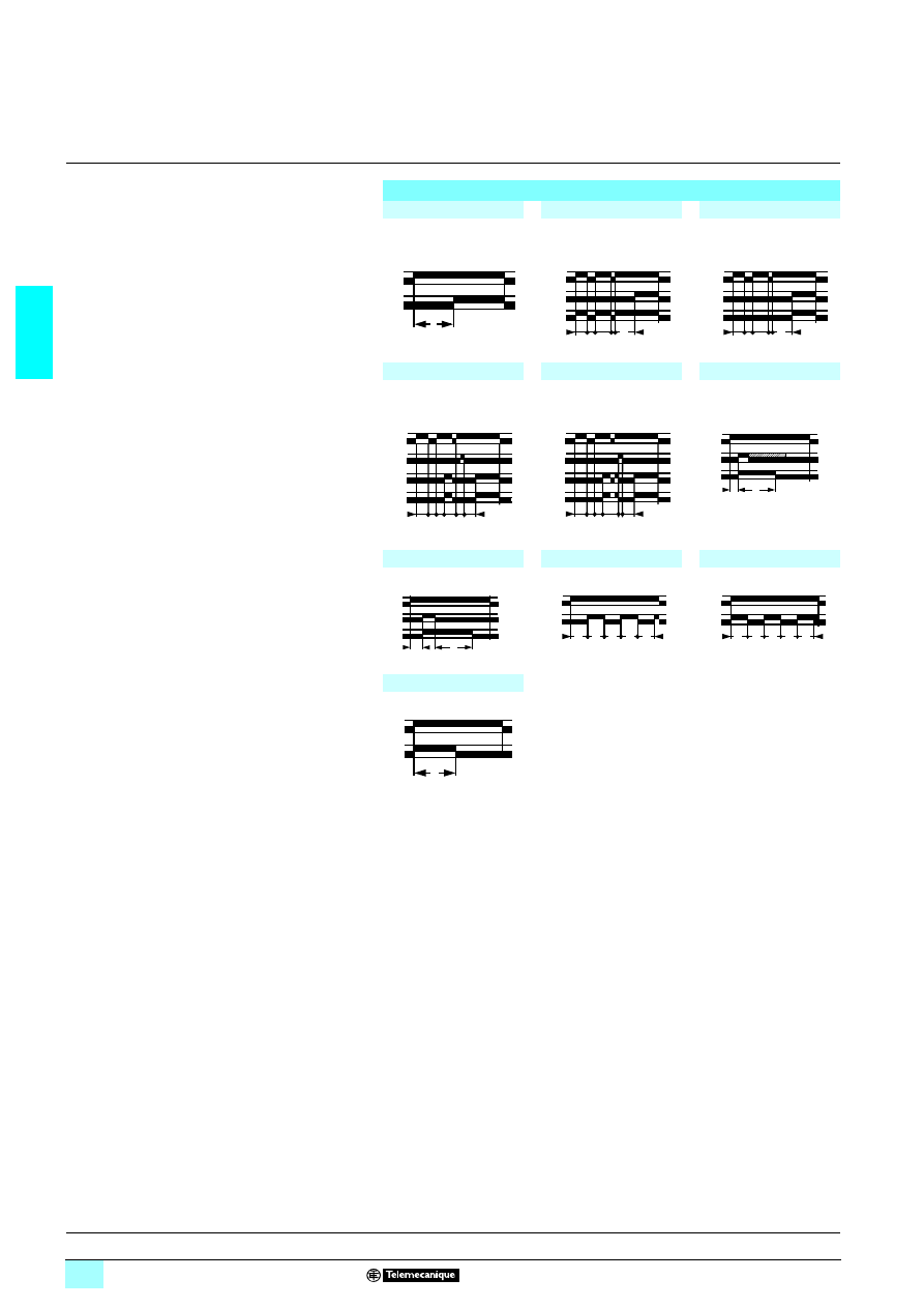
2/68
2
Functions
2
Zelio Time - timing relays
2
Panel-mounted, plug-in, universal relays
Relay output, 1 or 2 contacts
1 Multifunction or single function
1 Multi-range
1 Multivoltage
1 1 or 2 relay outputs
1 Reset function on front panel (RE 88 857 30
1111
)
1 Memory in the event of mains power failure
(RE 88 857 30
1111
)
1 Locking of access to programming
(RE 88 857 10
1111
and RE 88 857 00
1111
)
1 Upcount or downcount mode
1 Internal supply by lithium battery (10 years at 20 °C)
Function diagrams
Function A
Function A1
Function A2
Delay on energisation
1 timed contact
Delay on energisation
1 timed contact
1 instantaneous contact
Delay on energisation
2 timed contacts
Function AM
Function AMt
Function B
Delay on energisation
Memory during the time delay
period. Reset
Delay on energisation
Memory during and after the
time delay period. Reset
Timing on impulse, one shot
Function C
Function D
Function Di
Off-delay
Flashing relay
Flashing relay
Function H
Timing on energisation
2-10
1-3-4
T
2-10
8-9-11
T
t1<T t2<T
1-3-4
2-10
1-3-4
8-9-11
T
t1<T t2<T
2-5
T
t1
T=t1+t2
1-3-4
8-9-11
t
2-10
t2
2-5
T
t1
T=t1+t2
1-3-4
8-9-11
2-10
t2
2-10
2-5
T
1-3-4
∞
2-10
2-5
1-3-4
∞
T
2-10
1-3-4
T
T
T
T
T
2-10
1-3-4
T
T
T
T
T
2-10
1-3-4
T
Characteristics :
page 2/66
Schemes :
page 2/67
References :
page 2/69
Dimensions :
page 2/69
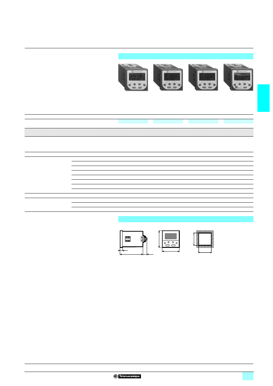
2/69
2
References,
dimensions
2
Zelio Time - timing relays
2
Panel-mounted, plug-in, universal relays
References
Plug-in
8-pin
11-pin
8-pin
11-pin
Functions
Single function
Multifunction
Multifunction
Multifunction
A
A, B, C, D, Di, H
A, B, C, D, Di, H
A1, A2, AM, AMt
Timing ranges
99.99 s, 999.9 s, 9999 s, 99 min 59 s, 99.99 min, 999.9 min, 9999 min, 99 h 59 min, 99.99 h,
999.9 h, 9999 h
Relay output
2 timed C/O
contacts
1 timed C/O contact
1 timed C/O contact
1 timed C/O contact
1 timed or
instantaneous
C/O contact
Rated current
2 x 5 A
8 A
8 A
2 x 8 A
Voltages
1312 V and 23or31 24…48 V –
RE 88 857 103
RE 88 857 003
–
1312 V and 23or31 42…48 V –
–
–
RE 88 857 302
23or31324 V
RE 88 857 409
–
–
–
23or31324 V and 2 110 V
–
–
–
RE 88 857 307
1 or32 24 V and 1 110…240 V –
RE 88 857 105
RE 88 857 005
–
1 or32 24 V and 1 220…240 V –
–
–
RE 88 857 301
23110 V
RE 88 857 406
–
–
–
23220…240 V
RE 88 857 400
–
–
–
Weight (kg)
0.140
0.100
0.100
0.140
Socket (1)
8-pin
RUZ 1D
–
RUZ 1D
–
11-pin
–
RUZ 1A
–
RUZ 1A
Weight (kg)
0.067
0.067
0.067
0.067
(1) These products are sold in packs of 10.
Dimensions
Panel cut-out
56
11
90
56
11
91
56
11
91
56
11
92
48
48
9,7
16
74,2
VALID
MODE
45
+0.6
0
45
+0.6
0
Characteristics :
page 2/66
Schemes :
page 2/67
Functions :
page 2/68
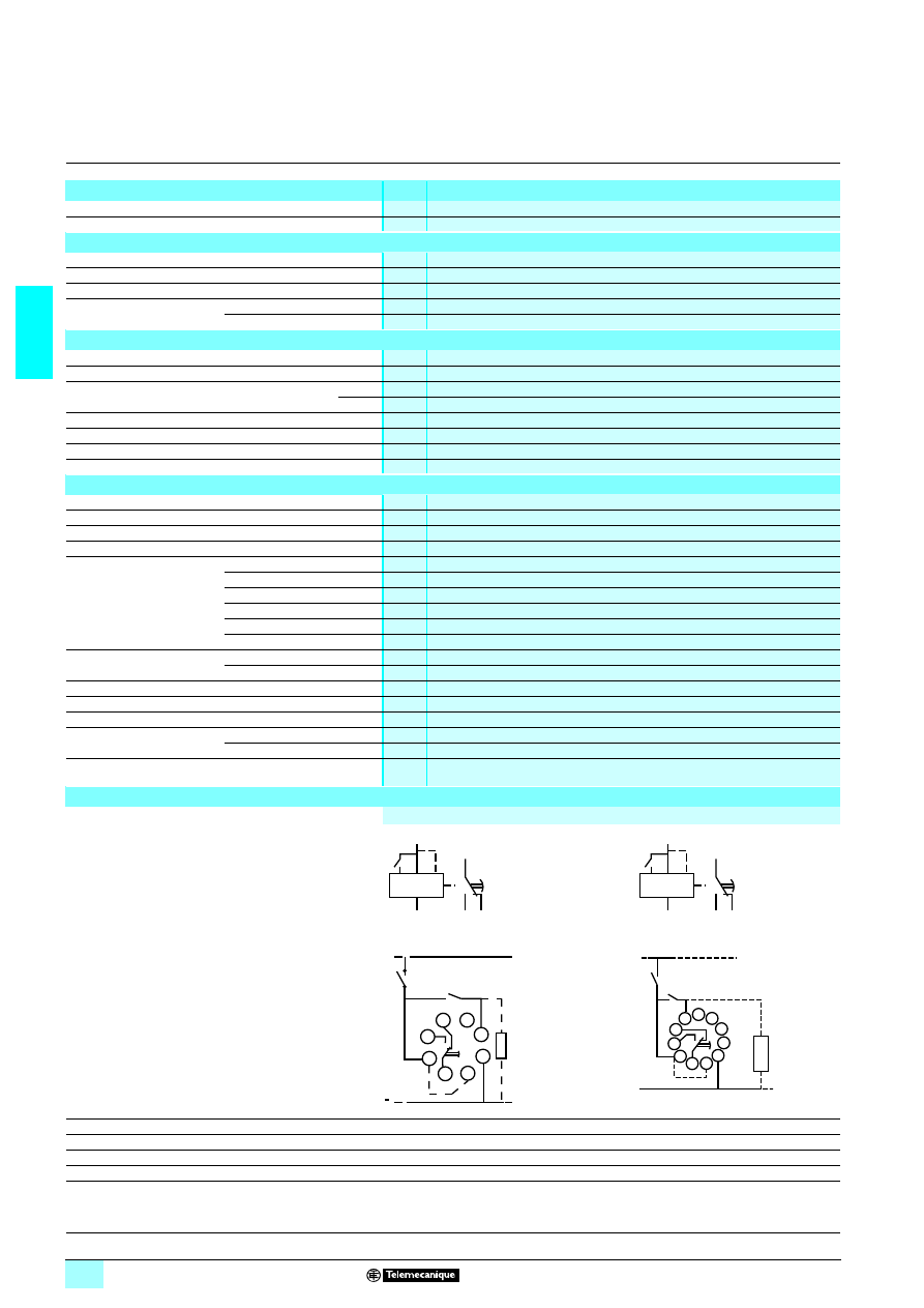
2/70
2
Characteristics,
schemes
2
Zelio Time - timing relays
2
Panel-mounted, plug-in, universal relays
Display characteristics
Number of digits
4
Digit height
mm
7
Timing characteristics
Repeat accuracy (with constant parameters)
± 0.03 % ± 20 ms
Full scale setting accuracy
± 0.03 % ± 20 ms
Minimum duration of control impulse
ms
50
Maximum reset time
by de-energisation
During time delay period
ms
50
After time delay period
ms
50
Output characteristics
Rated current
A
238, 138
Maximum switching voltage
V
23250, 1330
Maximum breaking capacity on a resistive load
2
VA
2000
1
W
190
Maximum permissible current
A
15 < 0.01 s
Minimum current
mA
100
Electrical life at I
max
4
4
4
4 250 V resistive
100 000 operating cycles
Mechanical life
5 million operating cycles
General characteristics
Product certifications
u UR cs, CSA
Conforming to standards
IEC 255, VDE 0435-2021
Permissible voltage variation
- 15 …+ 10 %
Immunity to microbreaks
s
< 0.03
Maximum power
consumption
1 24 V
W
0.5
1 48 V
W
1.5
2324 V
VA
1
2348 V
VA
1.5
23110 V
VA
4
23230 V
VA
12
Temperature limits
Operation
°C
- 10…+ 60
Storage
°C
- 30…+ 70
Front panel degree of protection
IP 65
Insulation
Conforming to standards VDE 0110 and IEC 225 Group C
Protection class
Conforming to standards UTE C 20010, IEC 529, DIN 40050
Fixing
Panel-mounting
By clip
Base-mounted
On socket
Material
Self-extinguishing UL 94 grade Vo
Internal schemes
Terminal referencing
(1) Another load may be connected.
8-pin relay
11-pin relay
2-10 or 2-7 supply
5
5
Link (2-11) or (2-8)
2/ 1 24 V supply
5
5
2-5 or 2-6 control or reset contact
5
5
1-3-4 timed output contact
5
5
1
7
3 4
6
2
8
-
+
1
10
3 4
5
2
11
-
+
6
7
8
1
2
3
4
5
~
+
U
~
Start
(1)
+
~
9
U
6
7
8
10
11
1
2
3
4
5
-
~
Start
(1)
References :
page 2/71
Dimensions :
page 2/71
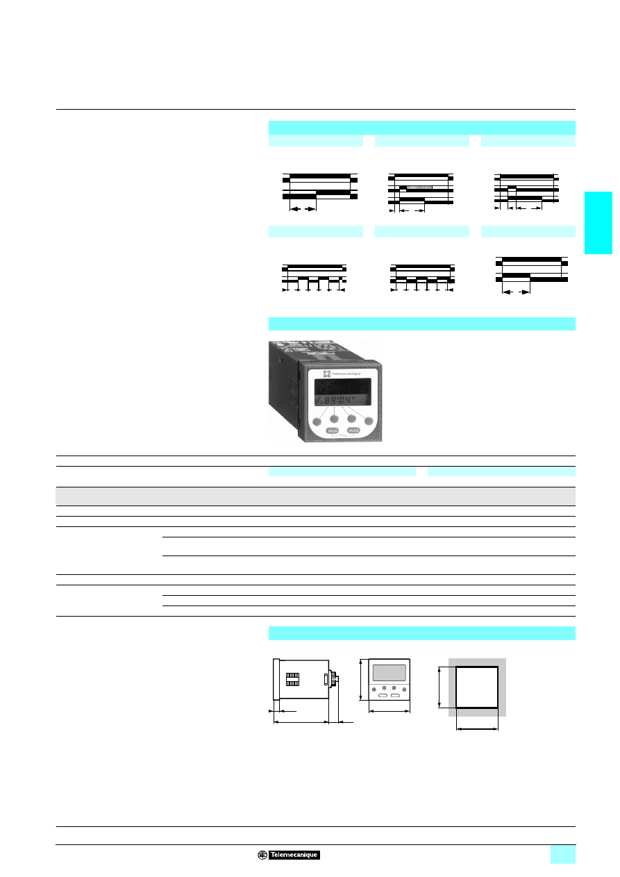
2/71
2
Functions,
references,
dimensions
2
Zelio Time - timing relays
2
Panel-mounted, plug-in, universal relays
Relay output, 1 C/O contact
1 Red illuminated display
1 Multifunction
1 Multi-range
1 Multivoltage
1 1 relay output
1 Locking of access to programming
1 Upcount or downcount mode
1 Internal supply by lithium battery (10 years at 20 °C)
Function diagrams
Function A
Function B
Function C
Delay on energisation
1 timed contact
Timing on impulse, one shot
Off-delay
Function D
Function Di
Function H
Flashing relay
Flashing relay
Timing on energisation
References
Plug-in
8-pin
11-pin
Functions
Multifunction
Multifunction
A, B, C, D, Di, H
A, B, C, D, Di, H
Timing ranges
99.99 s, 999.99 s, 9999 s, 99 min 59 s, 99.99 min, 999.9 min, 9999 min, 99 h 59 min, 99.99 h,
999.9 h, 9999 h
Relay output
1 timed C/O contact
1 timed C/O contact
Rated current
8 A
8 A
Voltages
2 or 1 24 V and 2 or 1 48 V RE 88 857 604
RE 88 857 704
2 or 1 24 V and 2 110 V,
50/60 Hz
RE 88 857 607
RE 88 857 707
2 or 1 24 V and 2 24…240 V,
50/60 Hz
RE 88 857 601
RE 88 857 701
Weight (kg)
0.100
0.100
Socket (1)
8-pin
RUZ 1D
–
11-pin
–
RUZ 1A
Weight (kg)
0.067
0.067
(1) These products are sold in packs of 10.
Dimensions
Panel cut-out
2-10
1-3-4
T
2-10
2-5/6
T
1-3-4
∞
2-10
2-5/6
1-3-4
∞
T
2-10
1-3-4
T
T
T
T
T
2-10
1-3-4
T
T
T
T
T
2-10
1-3-4
T
56
14
61
MODE
VALID
9,7
74,2
16
48
48
45
+ 0,6
0
45
+ 0,6
0
Characteristics :
page 2/70
Schemes :
page 2/70
Wyszukiwarka
Podobne podstrony:
Ch2 NonConventionalEnergygyandUtilisationResources 2 20 2 22
Ch2 NonConventionalEnergygyandUtilisationResources 2 1 2 16
ch2 53ul5zwpp635kbzi5kvppal6omvvld4g2uo6lmi 53UL5ZWPP635KBZI5KVPPAL6OMVVLD4G2UO6LMI
ch2 (2)
Ch2 E7
ROZKLAd ch2, Kwantyle c2(p,v) rzędu p rozkładu c2 o
ch2
Ch2 E3
Ch2 E6
Ch2 E5
fema453 ch2
Ch2 Q1
ch2-chromo, spektro, Chromatografia
Ch2 FuelResourcesFromTheForest
Ch2 E1
ch2 040802
ch2
CH2 (3)
więcej podobnych podstron