
FM 23-10
CHAPTER 2
EQUIPMENT
This chapter describes the equipment necessary for the sniper to
effectively peform his mission. The sniper carries only what is
essential to successfully complete his mission. He requires a
durable rifle with the capability of long-range precision fire. The
current US Army sniper weapon system is the M24. (See Appendix
B for the M21 sniper weapon system.)
Section I
M24 SNIPER WEAPON SYSTEM
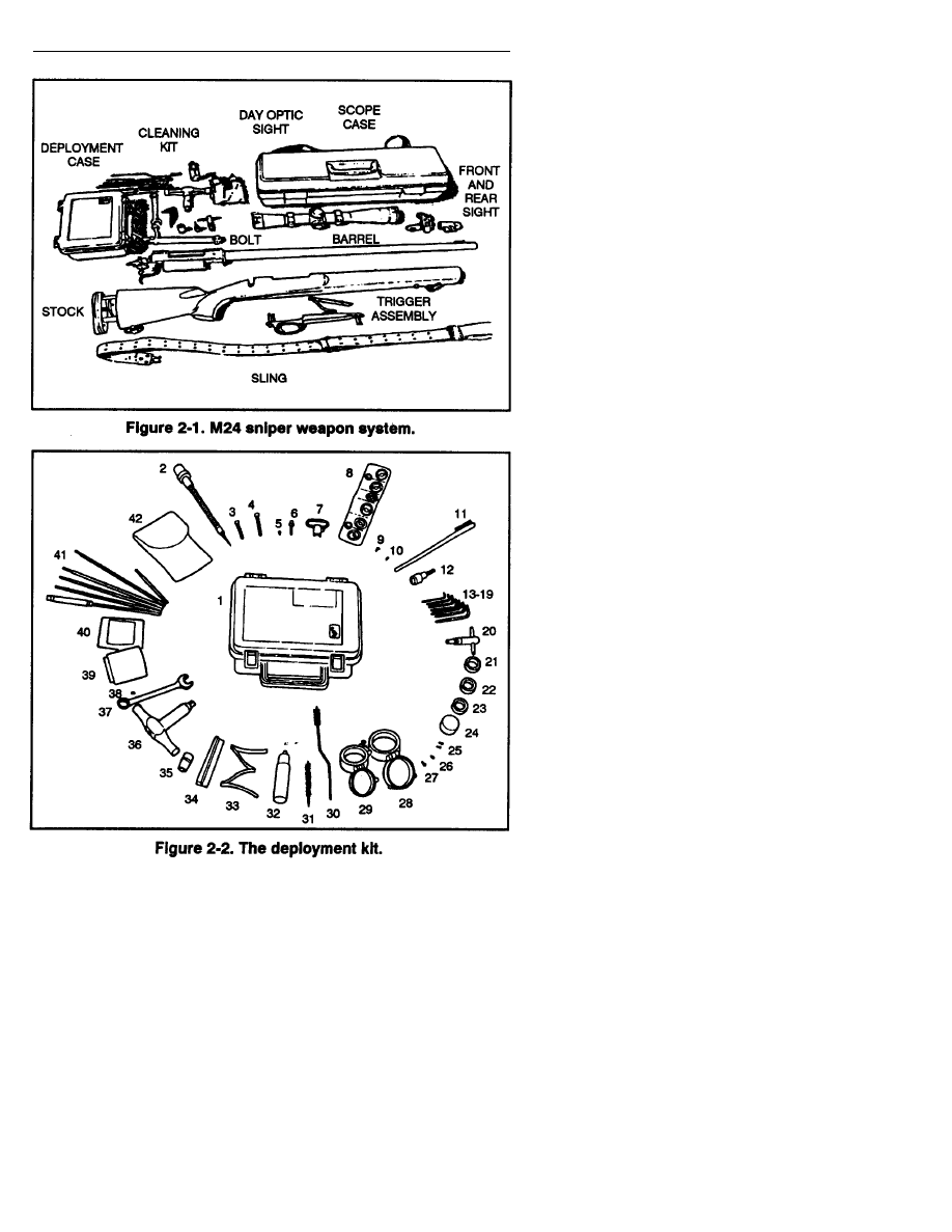
The M24 sniper weapon system is a 7.62-mm, bolt-action, six-shot repeating
rifle (one round in the chamber and five rounds in the magazine). It is
designed for use with either the M3A telescope (day optic sight) (usually
called the M3A scope) or the metallic iron sights. The sniper must know
the M24’s components, and the procedures required to operate them
(Figure 2-1, page 2-2). The deployment kit is a repair/maintenance kit
with tools and repair parts for the operator to perform operator level
maintenance (Figure 2-2, page 2-3.)
2-1
FM 23-10
2-2

FM 23-10
2-3
FM 23-10
2-1. OPERATIONS AND FUNCTIONS
To operate the M24 sniper weapon system, the sniper must know the
information and instructions pertaining to the safety, bolt assembly,
trigger assembly, and stock adjustment.
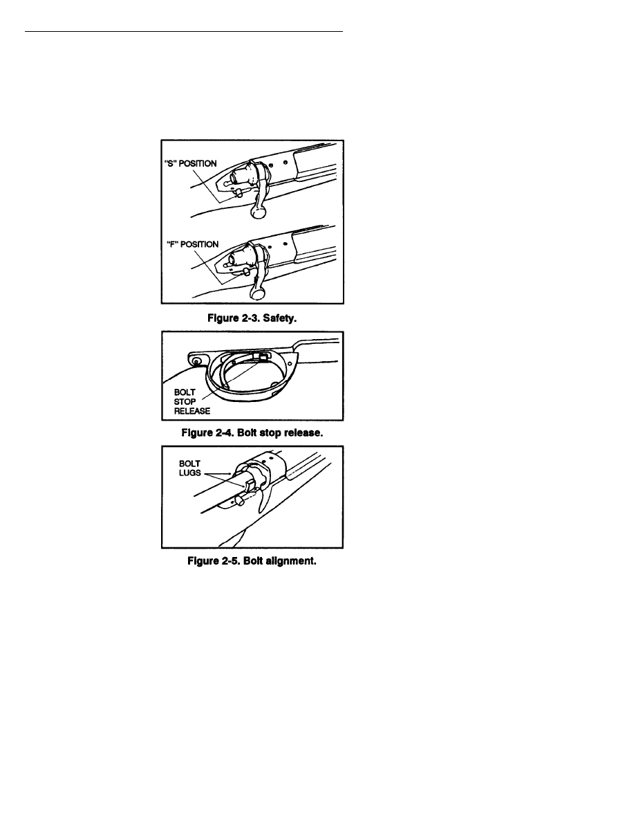
a. Safety. The safely is located on the right rear side of the receiver.
When properly engaged, the safety provides protection against accidental
discharge in normal usage.
(1) To engage the safety,
place it in the “S” position
(Figure 2-3).
(2) Always place the
safety in the “S” position
before handling, loading, or
unloading the weapon.
(3) When the weapon is
ready to be fired, place the
safety in the “F” position
(Figure 2-3).
b. Bolt Assembly. The
bolt assembly locks the
cartridge into the chamber
and extracts the cartridge
from the chamber.
(1) To remove the bolt
from the receiver, release the
internal magazine, place the
safety in the “S” position,
raise the bolt handle, and pull
it back until it stops. Then
push the bolt stop release
(Figure 2-4) and pull the bolt
from the receiver.
(2) To replace the bolt,
ensure the safety is in the “S”
position, align the lugs on the
bolt assembly with the
receiver (Figure 2-5), slide
the bolt all the way into the
receiver, and then push the
bolt handle down.
2-4
FM 23-10
WARNING
NEVER REMOVE THE TRIGGER MECHANISM, OR MAKE
ADJUSTMENTS TO THE TRIGGER ASSEMBLY, EXCEPT
FOR THE TRIGGER PULL FORCE ADJUSTMENT.
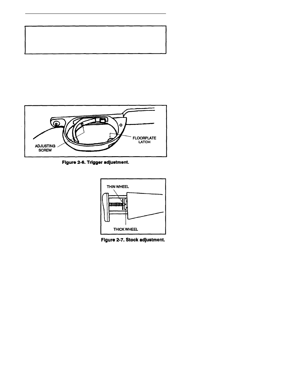
c. Trigger Assembly. Pulling the trigger fires the rifle when the safety
is in the “F” position. The operator may adjust the trigger pull force from
a minimum of 2 pounds to a maximum of 8 pounds. This is done using
the l/16-inch socket head screw key provided in the deployment kit.
Turning the trigger adjustment screw (Figure 2-6) clockwise increases the
force needed to pull the trigger. Turning it counterclockwise decreases
the force needed. This is the only trigger adjustment the sniper
should make.
d. Stock Adjustment. The M24’s
stock has an adjustable butt plate to
accommodate the length of pull.
The stock adjustment (Figure 2-7)
consists of a thin wheel and a thick
wheel. The thick wheel adjusts the
shoulder stock. The thin wheel locks
the shoulder stock.
(1) Turn the thick wheel clock-
wise to lengthen the stock.
(2) Turn the thick wheel counter-
clockwise to shorten the stock.
2-5
FM 23-10
(3) To lock the shoulder stock into position, turn the thin wheel
clockwise against the thick wheel.
(4) To unlock the shoulder stock, turn the thin wheel counter-
clockwise away from the thick wheel.
e. Sling Adjustment The sling helps hold the weapon steady
without muscular effort. The more the muscles are used the harder it is
to hold the weapon steady. The sling tends to bind the parts of the body
used in aiming into a rigid bone brace, requiring less effort than would be
necessary if no sling were used. When properly adjusted, the sling permits
part of the recoil of the rifle to reabsorbed by the nonfiring arm and hand,
removing recoil from the firing shoulder.
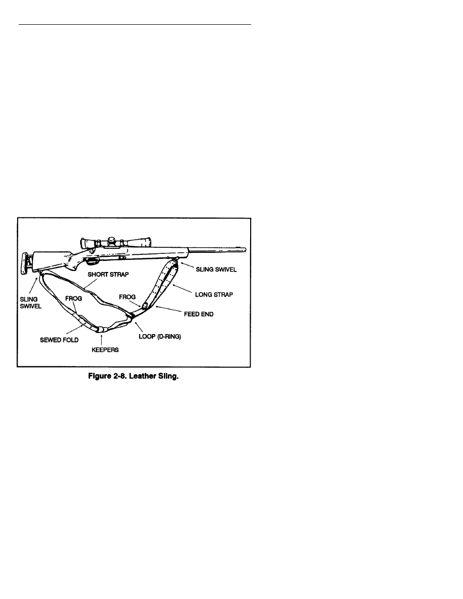
(1) The sling consists of two different lengths of leather straps joined
together by a metal D ring (Figure 2-8). The longer strap is connected to
the sling swivel on the rear stud on the forearm of the rifle. The shorter
strap is attached to the sling swivel on the buttstock of the rifle. There are
two leather loops on the long strap known as keepers. The keepers are
used to adjust the tension on the sling. The frogs are hooks that are used
to adjust the length of the sling.
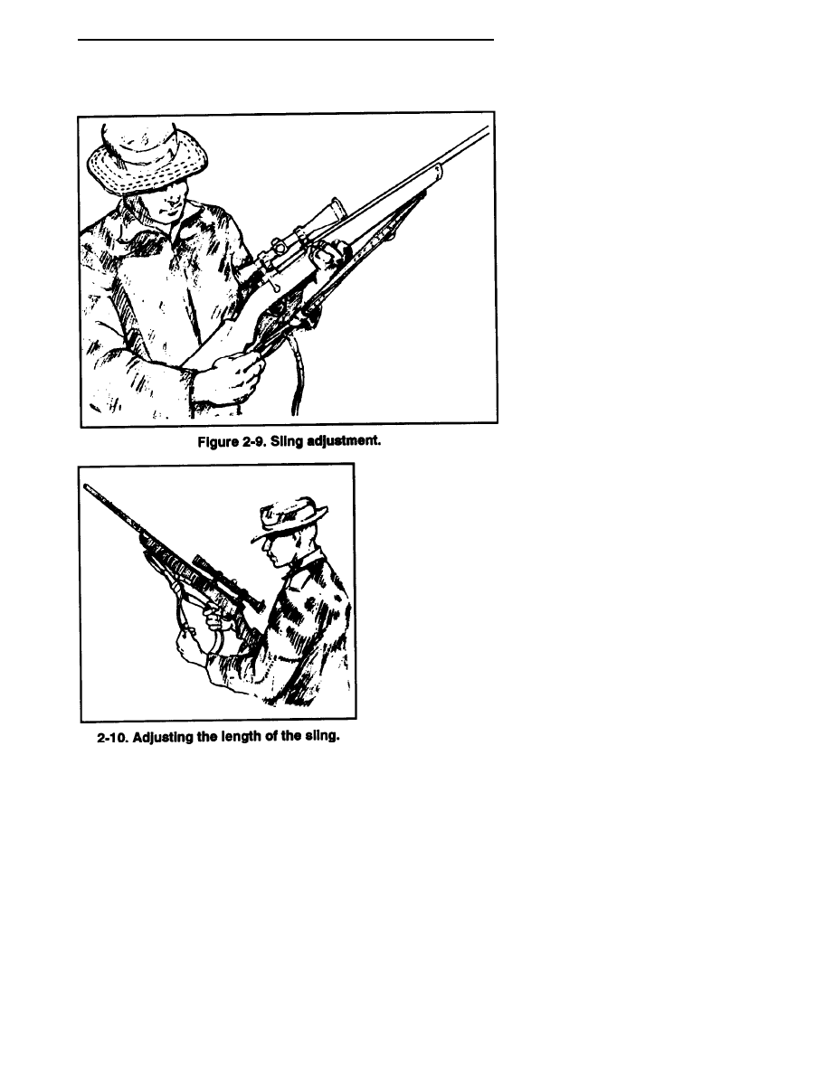
(2) To adjust the sling, the sniper disconnects the sling from the
buttstock swivel. Then, he adjusts the length of the metal D ring that joins
2-6
FM 23-10
the two halves of the sling. He then makes sure it is even with the comb
of the stock when attaching the sling to the front swivel (Figure 2-9).
(3) The sniper
adjusts the length of
the sling by placing the
frog on the long strap
of the sling in the 4th
to the 7th set of
adjustment holes on
the rounded end of the
long strap that goes
through the sling
swivel on the forearm
(Figure 2-10).
(4) After adjust-
ing the length, the
sniper places the
weapon on his firing
hip and supports the
2-7
FM 23-10
weapon with his firing arm. The sniper turns the sling away from him
90 degrees and inserts his nonfiring arm.
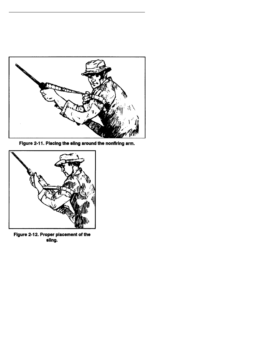
(5) The sniper slides the loop in the large section of the sling up the
nonfiring arm until it is just below the armpit (Figure 2-11). He then
slides both leather keepers down the sling until they bind the loop snugly
round the nonfiring arm.
(6) The sniper
moves his nonfiring
hand from the outside of
the sling to the inside of
the sling between the
rifle and the sling. The
sniper then grasps the
forearm of the weapon,
just behind the sling
swivel with his nonfiring
hand. He forces it
outward and away from
his body with the
nonfiring hand (Figure
2-12).
(7) The sniper
pulls the butt of the
2-8

FM 23-10
weapon into the pocket of his shoulder with the firing hand. He then
grasps the weapon at the small of the stock and begins the aiming process.
2-2. INSPECTION
The sniper performs PMCS on the M24 SWS. Deficiencies that cannot
be repaired by the sniper requires manufacturer repair. He must refer to
TM 9-1005-306-10 that is furnished with each weapon system. The sniper
must know this technical manual. He should cheek the following areas
when inspecting the M24:
a. Check the appearance and completeness of all parts.
b. Check the bolt to ensure it locks, unlocks, and moves smoothly.
c. Check the safety to ensure it can be positively placed into the “S”
and “F" positions easily without being too hard or moving too freely.
d. Check the trigger to ensure the weapon will not fire when the
safety is in the “S” position, and that it has a smooth, crisp trigger pull
when the safety is in the "F" position.
e. Check the trigger guard screws (rear of trigger guard and front of
internal magazine) for proper torque (65 inch-pounds).
f. Check the scope mounting ring nuts for proper torque
(65 inch-pounds).
g. Check the stock for any cracks, splits, or any contact it may have
with the barrel.
h. Inspect the scope for obstructions such as dirt, dust, moisture, or
loose or damaged lenses.
2-3. CARE AND MAINTENANCE
Maintenance is any measure taken to keep the M24 SWS in top
operating condition. It includes inspection, repair, cleaning and lubrication-
Inspection reveals the need for repair, cleaning, or lubrication. It also
reveals any damages or defects. When sheltered in garrison and
infrequently used, the M24 SWS must be inspected often to detect dirt,
moisture, and signs of corrosion, and it must be cleaned accordingly.
The M24 SWS that is in use and subject to the elements, however, requires
no inspection for cleanliness, since the fact of its use and exposure is
evidence that it requires repeated cleaning and lubrication.
a. M24 SWS Maintenance. The following materials are required for
cleaning and maintaining the M24 SWS:
One-piece plastic-coated .30 caliber cleaning rod with jag
(36 inches).
Bronze bristle bore brushes (.30 and .45 calibers).
Cleaning patches (small and large sizes).
2-9

FM 23-10
-“. —
Carbon cleaner.
Copper cleaner.
Rust prevention.
Cleaner, lubricant, preservative.
Rifle grease.
Bore guide (long action).
Swabs.
Pipe cleaners.
Medicine dropper.
Shaving brush.
Pistol cleaning rod.
Rags.
Camel’s-hair brush.
Lens tissue.
Lens cleaning fluid (denatured or isopropyl alcohol).
b. M24 SWS Disassembly. The M24 SWS will be disassembled only
when necessary, not for daily cleaning. For example, when removing an
obstruction from the SWS that is stuck between the stock and the barrel.
When disassembly is required, the recommended procedure is as follows:
Place the weapon so that is it pointing in a safe direction.
Ensure the safety is in the “S” position.
Remove the bolt assembly.
Loosen the mounting ring nuts on the telescope and remove the
telescope.
Remove the action screws.
Lift the stock from the barrel assembly.
For further disassembly, refer to TM 9-1005-306-10.
c. M24 SWS Cleaning Procedures. The M24 SWS must always be
cleaned before and after firing.
(1) The SWS must always be cleaned before firing. Firing a weapon
with a dirty bore or chamber will multiply and speed up any corrosive action.
Oil in the bore and chamber of a SWS will cause pressures to vary and
first-round accuracy will suffer. Clean and dry the bore and chamber
before departure on a mission and use extreme care to keep the SWS clean
and dry en route to the objective area. Firing a SWS with oil or moisture
in the bore will cause smoke that can disclose the firing position.
2-10

FM 23-10
(2) The SWS must be cleaned after firing since firing produces
deposits of primer fouling, powder ashes, carbon, and metal fouling.
Although ammunition has a noncorrosive primer that makes cleaning
easier, the primer residue can still cause rust if not removed. Firing leaves
two major types of fouling that require different solvents to remove
carbon fouling and copper jacket fouling. The SWS must be cleaned
within a reasonable time after firing. Use common sense when cleaning
between rounds of firing. Repeated firing will not injure the weapon if it
is properly cleaned before the first round is fired.
(3) Lay the SWS on a table or other flat surface with the muzzle away
from the body and the sling down. Make sure not to strike the muzzle or
telescopic sight on the table. The cleaning cradle is ideal for holding
the SWS.
(4) Always clean the bore from the chamber toward the muzzle,
attempting to keep the muzzle lower than the chamber to prevent the bore
cleaner from running into the receiver or firing mechanism. Be careful
not to get any type of fluid between the stock and receiver. If fluid does
collect between the stock and receiver, the receiver will slide on the
bedding every time the SWS recoils, thereby decreasing accuracy and
increasing wear and tear on the receiver and bedding material.
(5) Always use a bore guide to keep the cleaning rod centered in the
bore during the cleaning process.
(6) Push several patches saturated with carbon cleaner through the
barrel to loosen the powder fouling and begin the solvent action on the
copper jacket fouling.
(7) Saturate the bronze bristle brush (NEVER USE STAINLESS
STEEL BORE BRUSHES-THEY WILL SCRATCH THE BARREL)
with carbon cleaner (shake the bottle regularly to keep the ingredients mixed)
using the medicine dropper to prevent contamination of the carbon cleaner.
Run the bore brush through at least 20 times. Make sure the bore brush
passes completely through the barrel before reversing its direction;
otherwise, the bristles will break off.
(8) Use a pistol cleaning rod and a .45 caliber bronze bristle bore
brush, clean the chamber by rotating the patch-wrapped brush 8 to 10 times.
DO NOT scrub the brush in and out of the chamber.
(9) Push several patches saturated with carbon cleaner through the
bore to push out the loosened powder fouling.
(10) Continue using the bore brush and patches with carbon cleaner
until the patches have no traces of black/gray powder fouling and are
green/blue. This indicates that the powder fouling has been removed and
only copper fouling remains. Remove the carbon cleaner from the barrel
2-11

FM 23-10
with several clean patches. This is important since solvents should never
be mixed in the barrel.
(11) Push several patches saturated with copper cleaner through the
bore, using a scrubbing motion to work the solvent into the copper. Let the
solvent work for 10 to 15 minutes (NEVER LEAVE THE COPPER
CLEANER IN THE BARREL FOR MORE THAN 30 MINUTES).
(12) While waiting, scrub the bolt with the toothbrush moistened
with carbon cleaner and wipe down the remainder of the weapon with a cloth.
(13) Push several patches saturated with copper cleaner through
the barrel. The patches will appear dark blue at first, indicating the
amount of copper fouling removed. Continue this process until the
saturated patches have no traces of blue/green. If the patches continue to
come out dark blue after several treatments with copper cleaner, use the
bronze brush saturated with copper cleaner to increase the scrubbing action.
Be sure to clean the bronze brush thoroughly afterwards with hot running
water (quick scrub cleaner/degreaser is preferred) as the copper cleaner
acts upon its bristles as well.
(14) When the barrel is clean, dry it with several tight fitting patches.
Also, dry the chamber using the .45 caliber bronze bristle bore brush with
a patch wrapped around it.
(15) Run a patch saturated with rust prevention (not CLP) down the
barrel and chamber if the weapon is to be stored for any length of time.
Stainless steel barrels are not immune from corrosion. Be sure to remove
the preservative by running dry patches through the bore and chamber
before firing.
(16) Place a small amount of rifle grease on the rear surfaces of the
bolt lugs. This will prevent galling of the metal surfaces.
(17) Wipe down the exterior of the weapon (if it is not covered with
camouflage paint) with a CLP-saturated cloth to protect it during storage.
d. Barrel Break-in Procedure. To increase barrel life, accuracy, and
reduce cleaning requirement the following barrel break-in procedure must
be used. This procedure is best accomplished when the SWS is new or
newly rebarreled. The break-in period is accomplished by polishing the
barrel surface under heat and pressure. This procedure should only be done
by qualified personnel. The barrel must be cleaned of all fouling, both
powder and copper. The barrel is dried, and one round is fired. The barrel
is then cleaned again using carbon cleaner and then copper cleaner. The barrel
must be cleaned again, and another round is fired. The procedure must be
repeated for a total of 10 rounds. After the 10th round the SWS is then
tested for groups by firing three-round shot groups, with a complete barrel
cleaning between shot groups for a total of five shot groups (15 rounds total).
2-12
FM 23-10
The barrel is now broken in, and will provide superior accuracy and a
longer usable barrel life. Additionally, the barrel will be easier to clean
because the surface is smoother. Again the barrel should be cleaned at
least every 50 rounds to increase the barrel life.
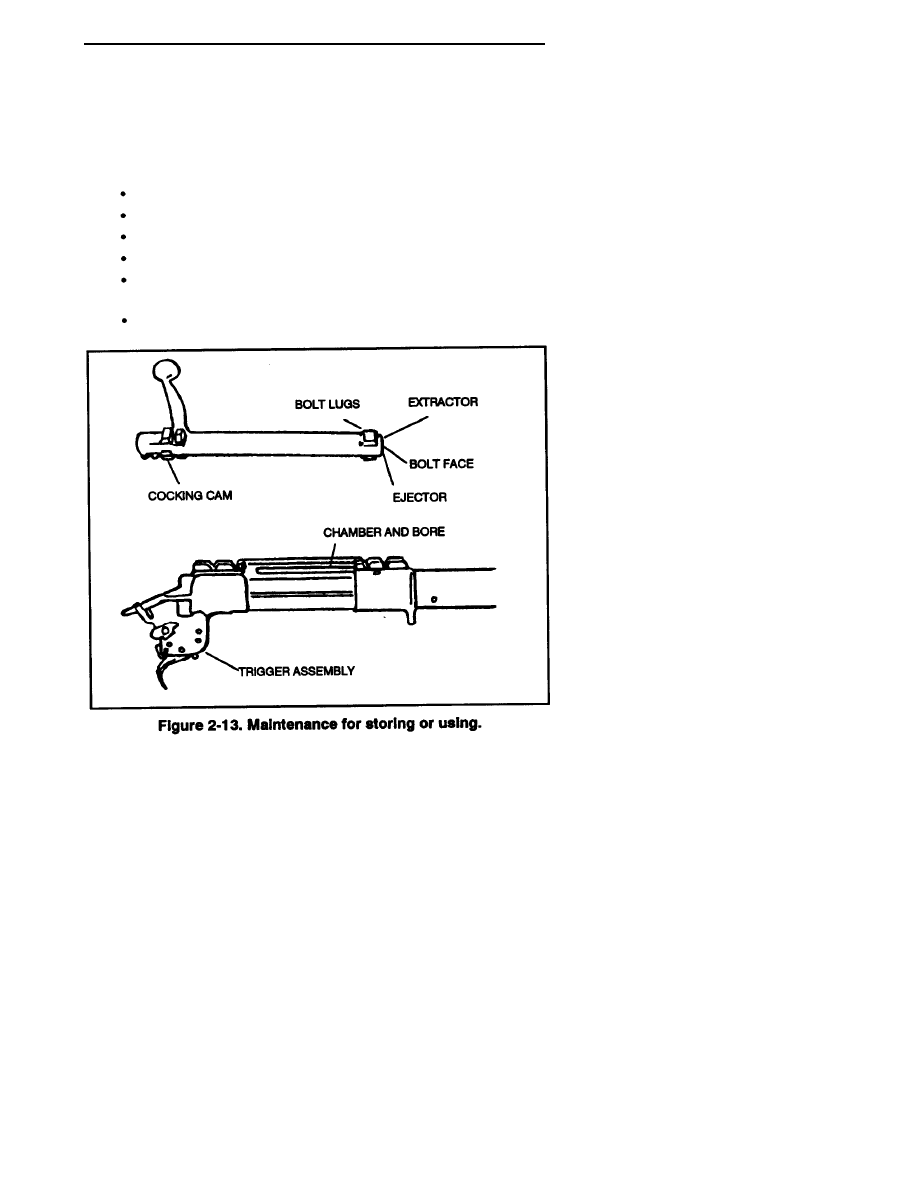
e. Storage. The M24 SWS should be stored (Figure 2-13) using the
following procedures:
Clear the SWS, close the bolt, and squeeze the trigger.
Open the lens caps to prevent gathering of moisture.
Hang the weapon upside down by the rear sling swivel.
Place all other items in the system case.
Transport the weapon in the system case during nontactical
situations.
Protect the weapon at all times during tactical movement.
NOTE: Rod clean swabs through the bore before firing.
This procedure ensures first-round accuracy and reduces
the signature.
2-13

FM 23-10
f. Cold Climates. In temperatures below freezing, the SWS must be
kept free of moisture and heavy oil, both of which will freeze, causing the
working parts to freeze or operate sluggishly. The SWS should be stored
in a room with the temperature equal to the outside temperature.
When the SWS is taken into a warm area, condensation occurs, thus
requiring a thorough cleaning and drying before taking it into the cold.
Otherwise, the condensation causes icing on exposed metal parts and optics.
The firing pin should be disassembled and cleaned thoroughly with a
decreasing agent. It should then be lubricated with CLP. Rifle grease
hardens and causes the firing pin to fall sluggishly.
g. Salt Water Exposure. Saltwater and saltwater atmosphere have
extreme and rapid corrosive effects on the metal parts of the SWS.
During periods of exposure, the SWS must be checked and cleaned as
often as possible, even if it means only lubricating the SWS. The SWS
should always be well lubricated, including the bore, except when
actually firing. Before firing, always run a dry patch through the bore,
if possible.
h. Jungle Operations (High Humidity). In hot and humid temper-
atures, keep the SWS lubricated and cased when not in use. Protect the
SWS from rain and moisture whenever possible. Keep ammunition clean
and dry. Clean the SWS, the bore, and the chamber daily. Keep the caps
on the telescope when not in use. If moisture or fungus develops on the
inside of the telescope, replace it. Clean and dry the stock daily. Dry the
carrying case and SWS in the sun whenever possible.
i. Desert Operations. Keep the SWS dry and free of CLP and grease
except on the rear of the bolt lugs. Keep the SWS free of sand by using
the carrying sleeve or carrying case when not in use. Protect the SWS by
using a wrap. Slide the wrap between the stock and barrel, then cross over
on top of the scope. Next, cross under the SWS (over the magazine) and
secure it. The SWS can still be placed into immediate operation but all
critical parts are covered. The sealed hard case is preferred in the desert
if the situation permits. Keep the telescope protected from the direct rays
of the sun. Keep ammunition clean and protected from the direct rays of
the sun. Use a toothbrush to remove sand from the bolt and receiver.
Clean the bore and chamber daily. Protect the muzzle and receiver from
blowing sand by covering with a clean cloth. To protect the free-floating
barrel of the SWS, take an 8- or 9-inch strip of cloth and tie a knot in
each end. Before going on a mission, slide the cloth between the barrel
and stock all the way to the receiver and leave it there. When in position,
slide the cloth out, taking all restrictive debris and sand with it.
2-14
FM 23-10
2-4. DISASSEMBLY
Occasionally, the weapon requires disassembly however, this should be
done only when absolutely necessary, not for daily maintenance.
An example of this would be to remove an obstruction that is stuck
between the forestock and the barrel. When disassembly is required, the
recommended procedure is as follows:
a. Point the rifle in a safe direction.
b. Put the safety in the “S” position.
c. Remove the bolt assembly.
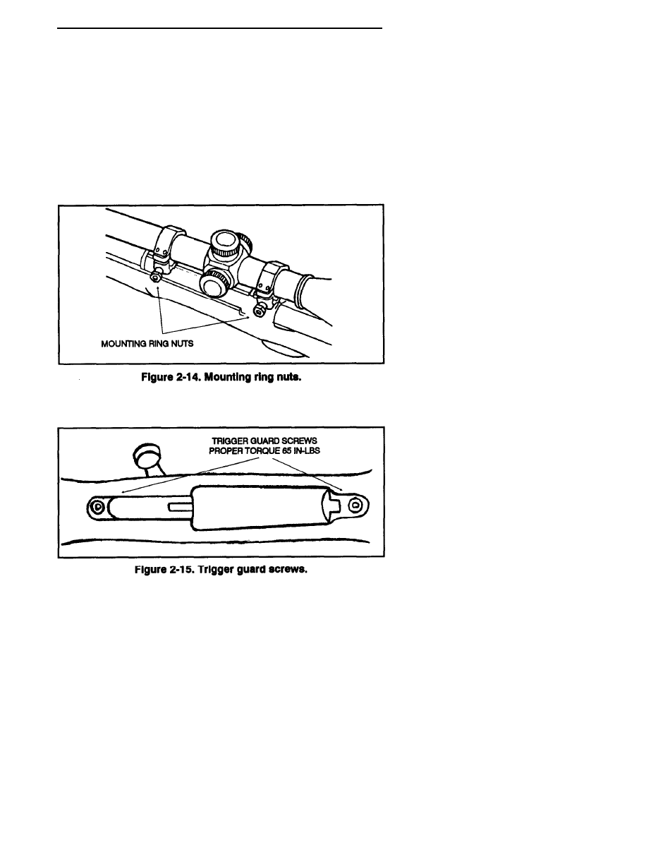
d. Use the 1/2-inch combination wrench, loosen the front and rear
mounting ring nuts (Figure 2-14) on the scope, and remove the scope.
e. Loosen the front and rear trigger guard screws (Figure 2-15).
2-15
FM 23-10
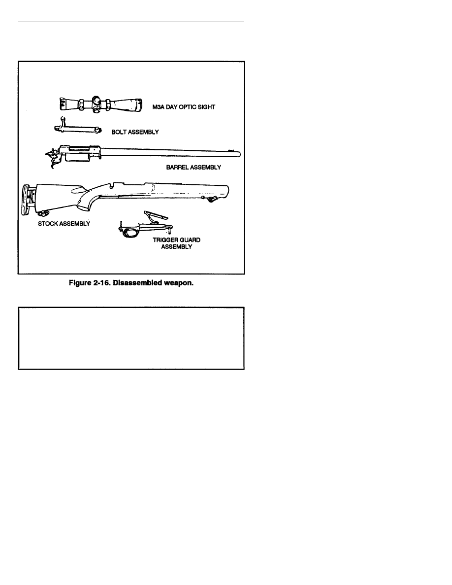
f. Lift the stock assembly from the barrel assembly (Figure 2-16).
g. Reassemble in reverse order.
WARNING
ALWAYS KEEP FINGERS AWAY FROM THE TRIGGER
UNTIL READY TO FIRE, MAKE SURE THE RIFLE IS NOT
LOADED BY INSPECTING THE MAGAZINE AND CHAMBER,
USE AUTHORIZED AMMUNITION AND CHECK THE
CONDITION BEFORE LOADING THE RIFLE.
2-16

FM 23-10
2-5. LOADING AND UNLOADING
Before loading, the sniper should ensure that the M24 SWS is on SAFE,
and the bolt is in a forward position. Before unloading, he should ensure
the M24 SWS is on SAFE, and the bolt is toward the rear.
a. Loading. The M24 has an internal, five-round capacity magazine.
To load the rifle—
(1) Point the weapon in a safe direction.
(2) Ensure the safety is in the “S” position.
(3) Raise the bolt handle. Then pull the bolt handle all the way back.
(4) Push five cartridges of 7.62-mm special ball ammunition one at
a time through the ejection port into the magazine. Ensure the bullet end
of the cartridges is aligned toward the chamber.
(5) To ensure proper functioning, cartridges should be set fully
rearward in the magazine.
(6) Use a finger to push the cartridges into the magazine and all the
way down. Slowly slide the bolt forward so that the bolt slides over the
top of the cartridges in the magazine.
(7) Push the bolt handle down. The magazine is now loaded.
(8) To chamber a cartridge, raise the bolt and pull it back until it stops.
(9) Push the bolt forward. The bolt removes a cartridge from the
magazine and pushes it into the chamber.
(10) Push the bolt handle down.
(11) To fire, place the safety in the “F” position and squeeze
the trigger.
WARNING
ENSURE THE CHAMBER AND MAGAZINE ARE CLEAR OF
CARTRIDGES.
b. Unloading. To unload the M24 SWS—
(1) Point the muzzle in a safe direction.
(2) Ensure the safety is in the “S” position.
(3) Raise the bolt handle.
(4) Put one hand over the top ejection port. Slowly pull the bolt handle
back with the other hand to remove the cartridge from the chamber.
(5) Remove the cartridge from the rifle.
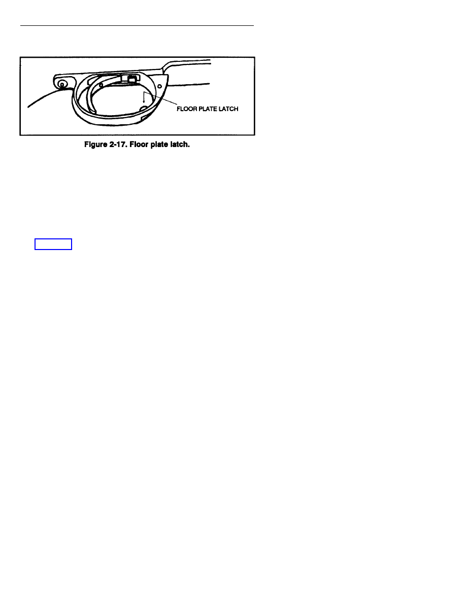
(6) Put a hand under the floor plate.
(7) Push the floor plate latch to release the floor plate (Figure 2-17,
page 2-18). The magazine spring and follower will be released from
the magazine.
(8) Remove the released cartridges.
2-17
FM 23-10
(9) Push in the magazine follower, then close the floor plate.
2-6. STORAGE
The M24 SWS should be stored as follows:
a. Hang the weapon in an upside down position by the rear
sling swivel.
b. Close the bolt and squeeze the trigger.
c. Open the lens caps to prevent gathering of moisture.
d. Place all other items in the system case.
e. Protect the weapon at all times during tactical movement.
.
Section II
AMMUNITION
The sniper uses the 7.62-mm special ball (M118) ammunition with the
sniper weapon system. The sniper must rezero the weapon each time he
fires a different type or lot of ammunition. This information should be
maintained in the sniper data book.
2-7. TYPES AND CHARACTERISTICS
The types and characteristics of sniper ammunition are described in
this paragraph.
a. M118 Special Ball Bullet. The 7.62-mm special ball (M118) bullet
consists of a gilding metal jacket and a lead antimony slug. It is a
boat-tailed bullet (rear of bullet is tapered) and weighs 173 grains. The tip
of the bullet is not colored. The base of the cartridge is stamped with the
year of manufacture and a circle that has vertical and horizontal lines,
sectioning it into quarters. Its spread (accuracy standard) for a 10-shot
group is no more than 12 inches at 550 meters (fired from an accuracy
barrel in a test cradle).
2-18

FM 23-10
b. M82 Blank Ammunition. The 7.62-mm M82 blank ammunition
is used during sniper field training. It provides the muzzle blast and flash
that can be detected by trainers during the exercises that evaluate the
sniper’s ability to conceal himself while firing his weapon.
NOTE: Regular 7.62-mm ball ammunition should be used only
in an emergency situation. No damage will occur to the barrel
when firing regular 7.62-mm ball ammunition. The M3A
scope's bullet drop compensator is designed for M118 special
ball, and there will be a significant change in zero. Therefore the
rifle will not be as accurate when firing regular 7.62-mm ball
ammunition. The 7.62-mm ball ammunition should be test fired
and the ballistic data recorded in the data book.
2-8. ROUND-COUNT BOOK
The sniper maintains a log of the number of cartridge fired through the
M24 SWS. It is imperative to accurately maintain the round-count
book as the barrel should be replaced after 5,000 rounds of firing.
The round-count book is issued and maintained in the arms room.
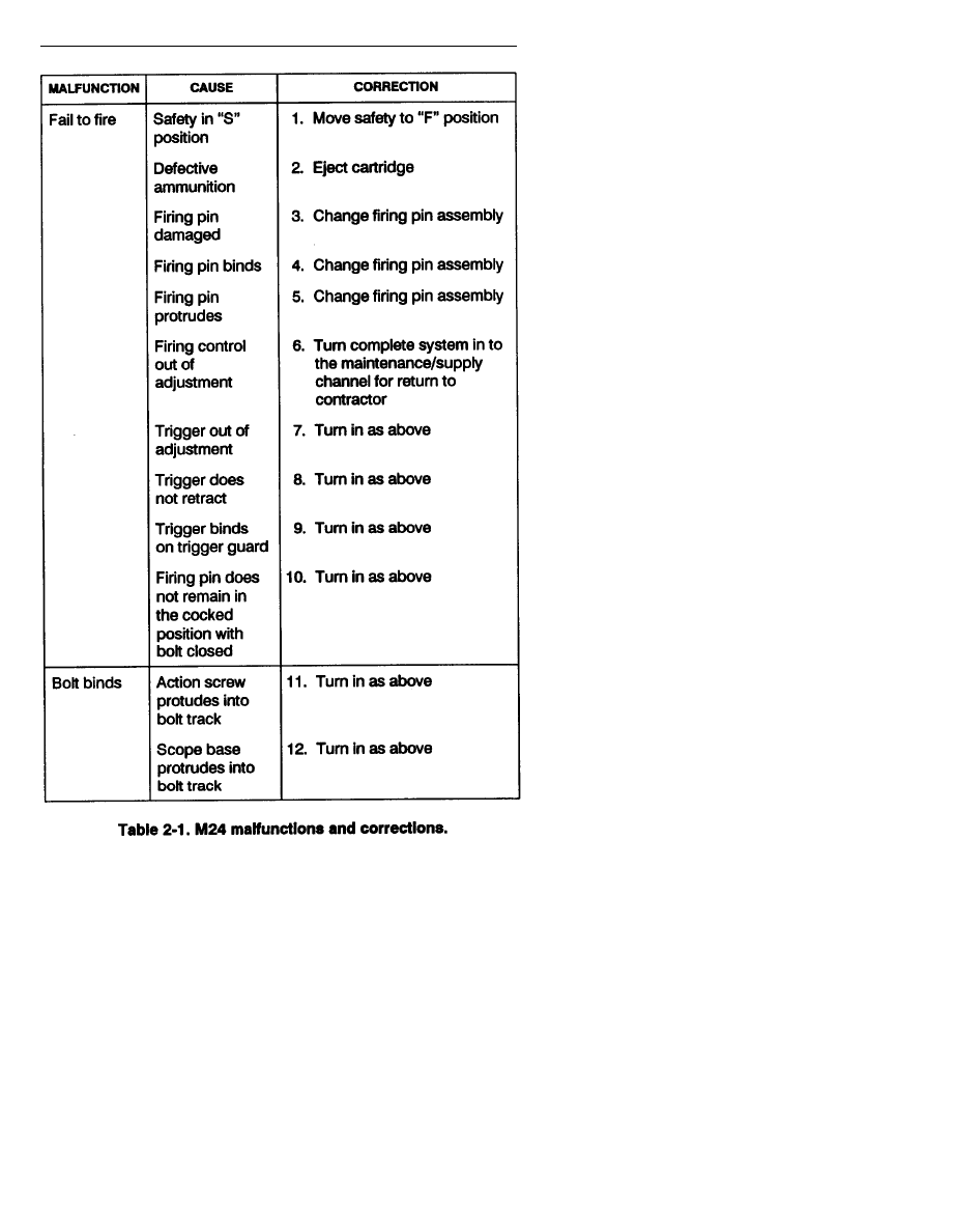
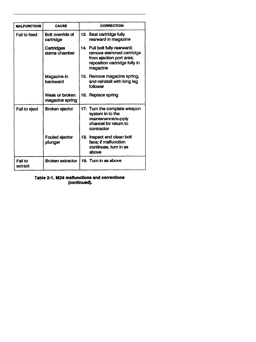
2-9. M24 MALFUNCTIONS AND CORRECTIONS
Table 2-1 does not reflect all malfunctions that can occur, or all causes and
corrective actions. If a malfunction is not correctable, the complete
weapon system must be turned in to the proper maintenance/supply
channel for return to the contractor (see shipment, TM 9-1005-306-10).
2-19
FM 23-10
2-20
FM 23-10
2-21

FM 23-10
Section III
SNIPER SIGHTING DEVICES
The sniper has two sighting devices: the M3A scope and iron sights.
The M3A scope allows the sniper to see the cross hairs and the image of
the target with identical sharpness. It can be easily removed and replaced
with less than 1/2 minute of angle change in zero. However, the M3A
scope should be left on the rifle. Iron sights are used only as a backup
sighting system and can be quickly installed.
2-10. M3A SCOPE
The M3A scope is an optical instrument that the sniper uses to improve
his ability to see his target clearly in most situations. Usually, the
M3A scope presents the target at an increased size (as governed by scope
magnification), relative to the same target at the same distance without a
scope. The M3A scope helps the sniper to identify recognize the target.
His increased sighting ability also helps him to successfully engage
the target.
NOTE: The adjustment dials are under the adjustment
dust cover.
a. M3A Scope Adjustments. The sniper must use the following
adjustment procedures on the M3A scope:
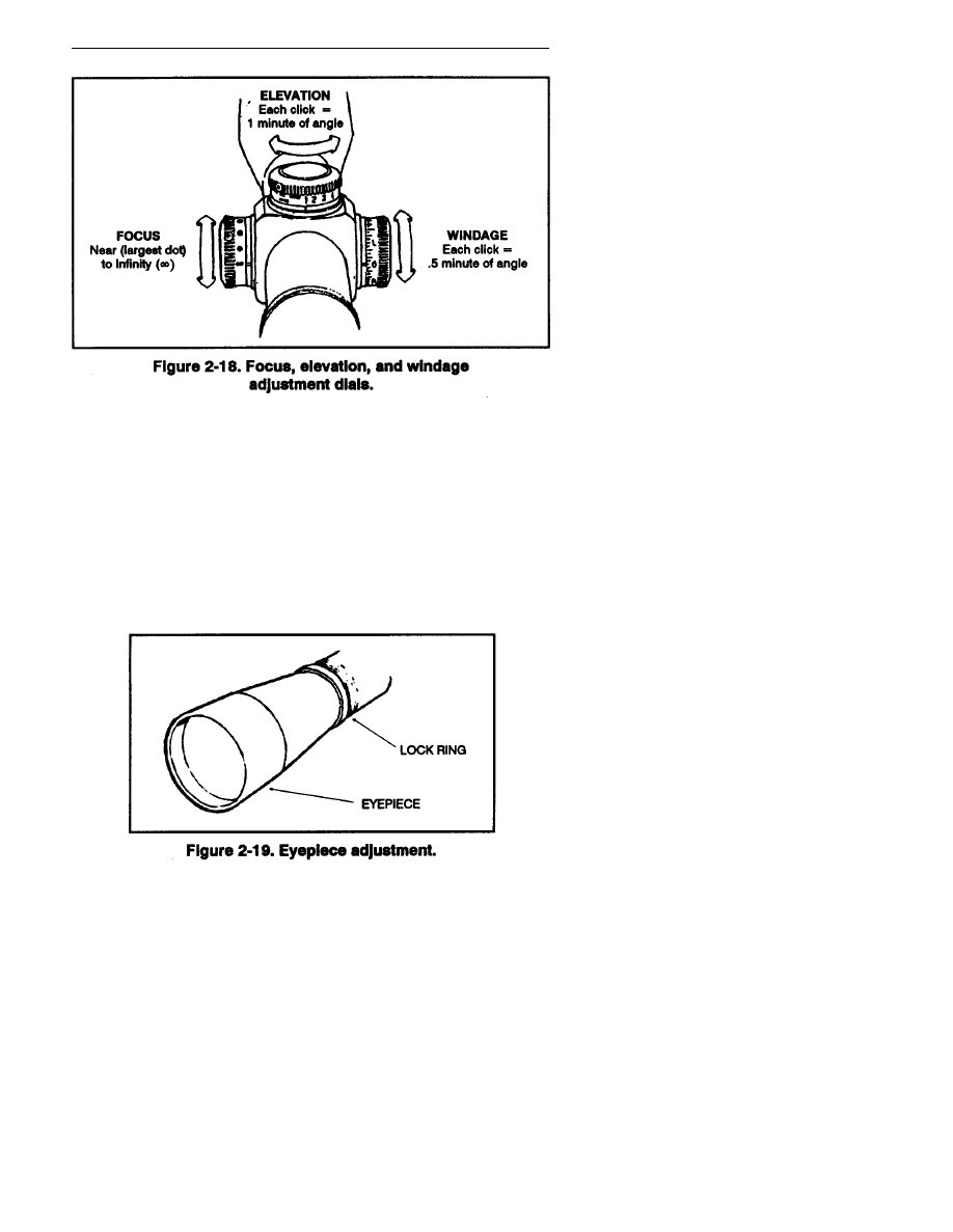
(1) Focus adjustment
dial.
The focus adjustment dial (Figure 2-18) is
on the left side of the scope barrel. This dial has limiting stops with the
two extreme positions shown by the infinity mark and the largest dot.
The focus adjustment dial keeps the target in focus. If the target is close,
the dial is set at a position near the largest dot.
NOTE: Each minute of angle is an angular unit of measure.
(2) Elevation adjustment dial. The elevation adjustment dial
(Figure 2-18) is on top of the scope barrel. This dial has calibrated index
markings from 1 to 10. These markings represent the elevation setting
adjustments needed at varying distances: 1 = 100 meters, 3 = 300
meters, 7 = 700 meters, and so on. Each click of the elevation dial equals
1 minute of angle.
(3) Windage adjustment dial. The windage adjustment dial
(Figure 2-18) is on the right side of the scope barrel. This dial is used to
make lateral adjustments to the scope. Turning the dial in the indicated
direction moves the point of impact in that direction. Each click on the
windage dial equals .5 minute of angle.
2-22
FM 23-10
(4) Eyepiece adjustment. The eyepiece (Figure 2-19) is adjusted by
turning it in or out of the barrel until the reticle appears crisp and clear.
Focusing the eyepiece should be done after mounting the scope.
The sniper grasps the eyepiece and backs it away from the lock ring.
He does not attempt to loosen the lock ring first; it loosens automatically
when he backs away from the eyepiece (no tools needed). The eyepiece
is turned several turns to move it at least 1/8 inch. It takes this much
change to achieve any measurable effect on the focus. The sniper looks
through the scope at the sky or a blank wall and checks to see if the reticle
appears sharp and crisp. He locks the lock ring after achieving
reticle clarity.
2-23
FM 23-10
WARNINGS
1. SECURELY FASTEN THE MOUNTING BASE TO THE
RIFLE. LOOSE MOUNTING MAY CAUSE THE M3A SCOPE
AND BASE MOUNT ASSEMBLY TO COME OFF THE RIFLE
WHEN FIRING, POSSIBLY INJURING THE FIRER.
2. DURING RECOIL PREVENT THE M3A SCOPE FROM
STRIKING THE FACE BY MAINTAINING AN AVERAGE
DISTANCE OF 2 TO 3 INCHES BETWEEN THE EYE AND
THE SCOPE.
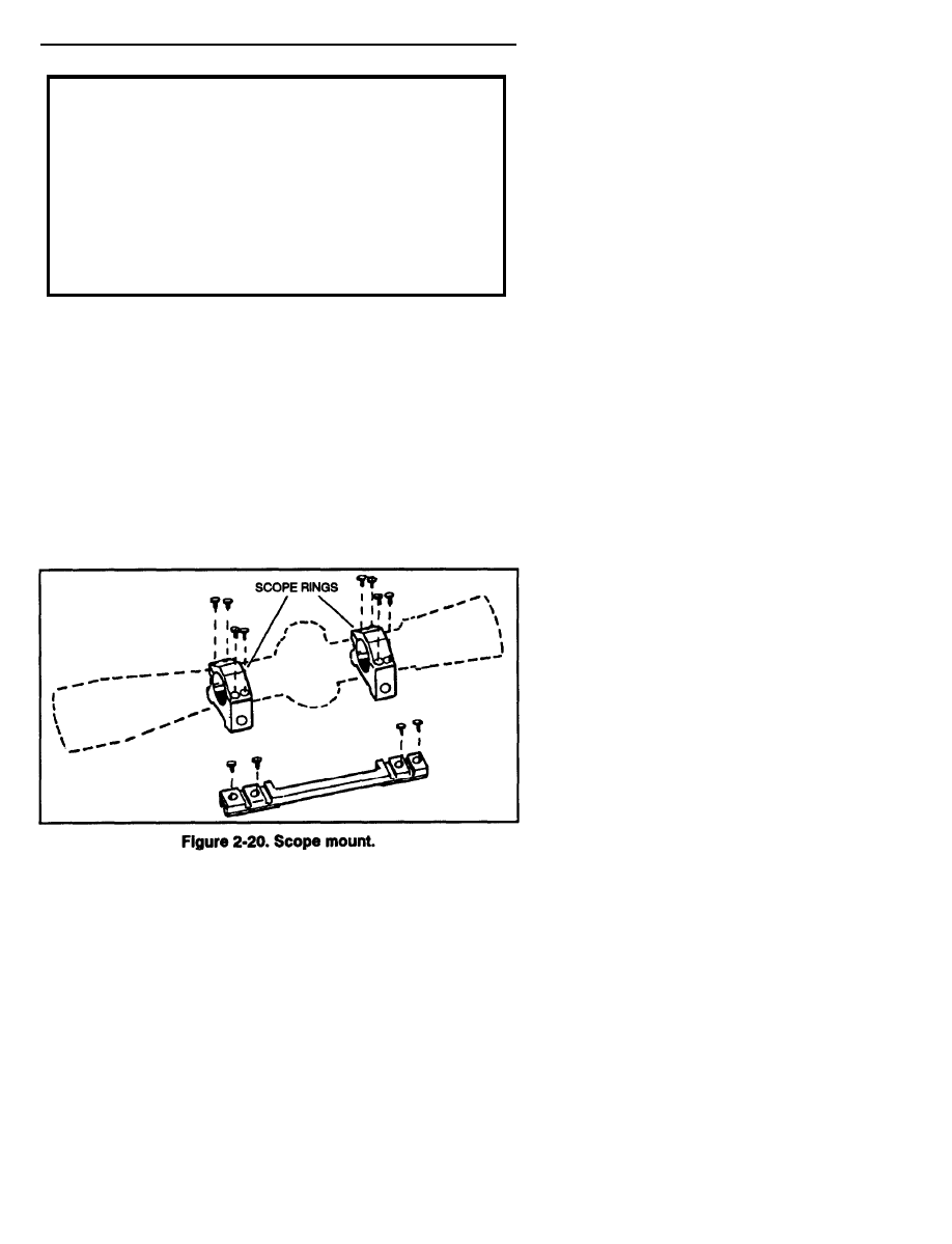
b. M3A Scope Mount. The M3A scope mount has a baseplate with
four screws; a pair of scope rings with eight ring screws, each with an upper
and lower ring half with eight ring screws and two ring mounting bolts
with nuts (Figure 2-20). The baseplate is mounted to the rifle by screwing
the four baseplate screws through the plate and into the top of
the receiver. The screws must not protrude into the receiver and
interrupt the functioning of the bolt. After the baseplate is mounted, the
scope rings are mounted.
NOTE: The M3A scope has two sets of mounting slots.
The sniper selects the set of slots that provides proper eye relief
(the distance that the eye is positioned behind the telescopic sight).
The average distance is 2 to 3 inches. The sniper adjusts eye
relief to obtain a full field of view.
2-24

FM 23-10
(1) Before mounting the M3A scope, lubricate the threads of each
mounting ring nut.
(2) Ensure smooth movement of each mounting ring nut and
mount claw.
(3) Inspect for burrs and foreign matter between each mounting ring
nut and mount claw. Remove burrs or foreign matter before mounting.
(4) Mount the sight and rings to the base.
NOTE: Once a set of slots is chosen, the same set should always
be used in order for the SWS to retain zero.
(5) Ensure the mounting surface is free of dirt, oil, or grease.
(6) Set each ring bolt spline into the selected slot.
(7) Slide the rear mount claw against the base and finger-tighten the
mounting ring nut.
(8) If the scope needs to be adjusted loosen the mounting ring nuts and
align the ring bolts with the other set of slots on the base Repeat this process.
(9) Slide the front mount claw against the base, and finger-tighten
the mounting ring nut.
(10) Use the T-handle torque wrench, which is preset to 65inch-pounds,
to tighten the rear mounting ring nut.
c. Care and Maintenance of the M3A Scope. Dirt, rough handling,
or abuse of optical equipment will result in inaccuracy and malfunction.
When not in use, the rifle and scope should be cased, and the lens should
be capped.
(1) Lens. The lens are coated with a special magnesium fluoride
reflection-reducing material. This coat is thin and great care is required
to prevent damage to it.
(a) To remove dust, lint, or other foreign matter from the lens, lightly
brush the lens with a clean camel’s-hair brush.
(b) To remove oil or grease from the optical surfaces, apply a drop
of lens cleaning fluid or robbing alcohol on a lens tissue. Carefully wipe
off the surface of the lens in circular motions (from the center to the
outside edge). Dry off the lens with a clean lens tissue. In the field, if the
proper supplies are not available, breathe heavily on the glass and wipe
with a soft, clean cloth.
(2) Scope. The scope is a delicate instrument and must be handled
with care. The following precautions will prevent damage
(a) Check and tighten all mounting screws periodically and always
before an operation. Be careful not to change the coarse windage
adjustment.
2-25

FM 23-10
(b) Keep the lens free from oil and grease and never touch them with
the fingers. Body grease and perspiration can injure them. Keep the cap
on the lens.
(c) Do not force the elevation and windage screws or knobs.
(d) Do not allow the scope to remain in direct sunlight, and avoid
letting the sun’s rays shine through the lens. The lens magnify and
concentrate sunlight into a pinpoint of intense heat, which is focused on
the mil-scale reticle. This may melt the mil dots and damage the
scope internally. Keep the lens covered and the entire scope covered
when not in use.
(e) Avoid dropping the scope or striking it with another object.
This could permanently damage the telescope as well as change the zero.
(f) To avoid damage to the scope or any other piece of sniper
equipment, snipers or armorers should be the only personnel handling
the equipment. Anyone who does not know how to use this equipment
could cause damage.
(3) Climate conditions. Climate conditions play an important part in
taking care of optical equipment.
(a) Cold climates. In extreme cold, care must be taken to avoid
condensation and congealing of oil on the glass of the optical equipment.
If the temperature is not excessive, condensation can be removed by
placing the instrument in a warm place. Concentrated heat must not be
applied because it causes expansion and damage can occur. Moisture may
also be blotted from the optics with lens tissue or a soft, dry cloth. In cold
temperatures, oil thickens and causes sluggish operation or failure.
Focusing parts are sensitive to freezing oils. Breathing forms frost, so the
optical surfaces must be cleaned with lens tissue, preferably dampened
lightly with alcohol. DO NOT apply alcohol on the glass of the optics.
(b) Jungle operations (high humidity). In hot and humid temperatures,
keep the caps on the scope when not in use. If moisture or fungus
develops on the inside of the telescope, replace it.
(c) Desert operations. Keep the scope protected from the direct rays.
of the sun.
(d) Hot climate and salt water exposure. The scope is vulnerable to
hot, humid climates and salt water atmosphere. It MUST NOT be
exposed to direct sunlight. In humid and salt air conditions, the scope
must be inspected, cleaned, and lightly oiled to avoid rust and corrosion.
Perspiration can also cause the equipment to rust; therefore, the
instruments must be thoroughly dried and lightly oiled.
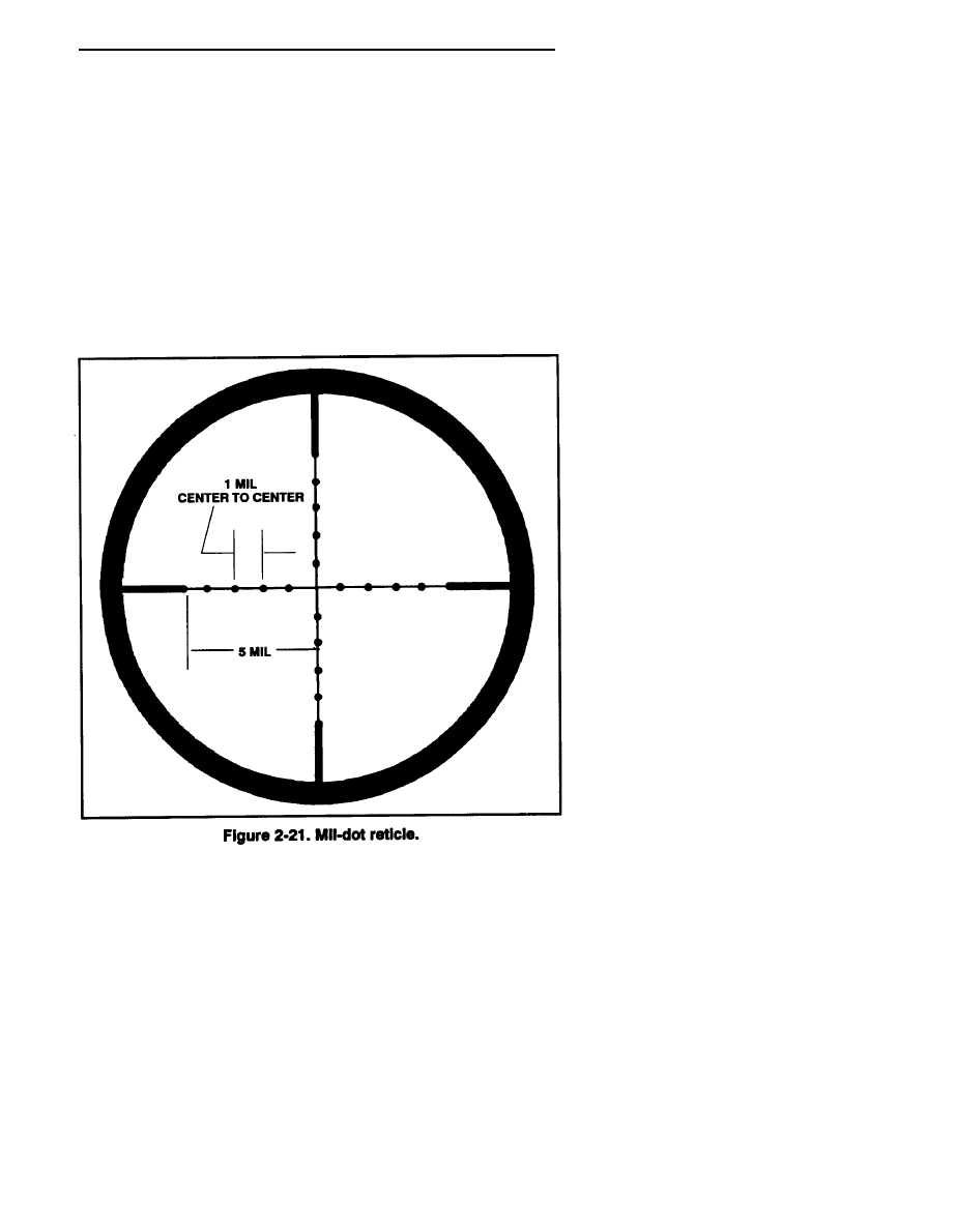
d. M3A Scope Operation. When using the M3A scope, the sniper
looks at the target and determines the distance to it by using the mil dots
2-26
FM 23-10
on the reticle. The mil-dot reticle (Figure 2-21) is a duplex-style reticle
that has thick outer sections and thin inner sections. Superimposed on
the thin center section of the reticle is a series of dots. There are 4 dots
on each side of the center and 4 dots above and below the center.
These 4 dots are spaced 1 mil apart, and 1 mil from both the center and
the start of the thick section of the reticle. This spacing allows the sniper
to make close estimates of target range, assuming there is an object of
known size (estimate) in the field of view. For example, a human target
appears to be 6 feet tall, which equals 1.83 meters tall, and at 500 meters,
3.65 dots high (nominally, about 3.5 dots high). Another example is a
l-meter target at a 1,000-meter range. This target is the height between
2 dots, or the width between 2 dots. If the sniper is given a good estimate
of the object’s size, then he may accurately determine target range using
the mil-dot system.
2-27

FM 23-10
e. Zeroing. Zeroing the M3A scope should be done on a
known-distance range (preferably 900 meters long) with bull’s-eye-type
targets (200-yard targets, NSN SR1-6920-00-900-8204). When zeroing
the scope, the sniper—
(1) Assumes a good prone-supported position 100 meters from
the target.
(2) Ensures the "l" on the elevation dial is lined up with the elevation
index line, and the “0” on the windage dial is lined up with the windage
index line.
(3) Fires three rounds at the center of the target, keeping the same
aiming point each time and triangulate.
(4) After the strike of the rounds has been noted, turns the elevation
and windage dials to make the needed adjustments to the scope.
Each click on the elevation dial equals one minute of angle.
One minute of angle at 100 meters equals 1.145 inches or about
1 inch.
Each click on the windage dial equals .5 minute of angle.
.5 minute of angle at 100 meters equals about .5 inch.
(5) Repeats steps 3 and 4 until a three-round shot group is centered
on the target.
(6) Once the shot group is centered, loosens the hex head screws on
the elevation and windage dials. He turns the elevation dial to the index
line marked “l” (if needed). He turns the windage dial to the index line
marked “0” (if needed) and tighten the hex head screws.
(7) After zeroing at 100 meters and calibrating the dial, confirms this
zero by firing and recording sight settings (see Chapter 3) at 100-meter
increments through 900 meters.
f. Field-Expedient Confirmation/Zeroing. The sniper may need to
confirm zero in a field environment. Examples are shortly after
receiving a mission, a weapon was dropped, or excessive climatic changes
as may be experienced by deploying to another part of the world.
Two techniques of achieving a crude zero are the 25-yard/900-inch method
and the observation of impact method.
(1) 25-yard/900-inch method. Dial the scope to 300 meters for
elevation and to “0” for windage. Aim and fire at a target that is at a
25-yard distance. Adjust the scope until rounds are impacting 5/8 of an
inch above the point of aim. To confirm, set the elevation to 500 meters.
The rounds should impact 2 1/4 inches above the point of aim.
(2) Observation of impact method. When a known distance range is
unavailable, locate a target so that the observer can see the impact of
2-28
FM 23-10
rounds clearly. Determine the exact range to the target, dial in the
appropriate range, and fire. Watch the impact of the rounds; the observer
gives the sight adjustments until a point of aim or point of impact
is achieved.
2-11. IRON SIGHTS
Depending on the situation, a sniper may be required to deliver an
effective shot at ranges up to 900 meters or more. This requires the sniper
to zero his rifle with the iron sights and the M3A scope at most ranges
that he can be expected to fire.
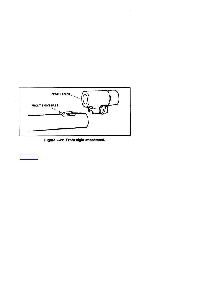
a. Mounting. To mount iron sights, the sniper must remove the
M3A scope first.
(1) Attach the front sight to the barrel, align the front sight and the
front sight base, and slide the sight over the base and tighten the screw
(Figure 2-22).
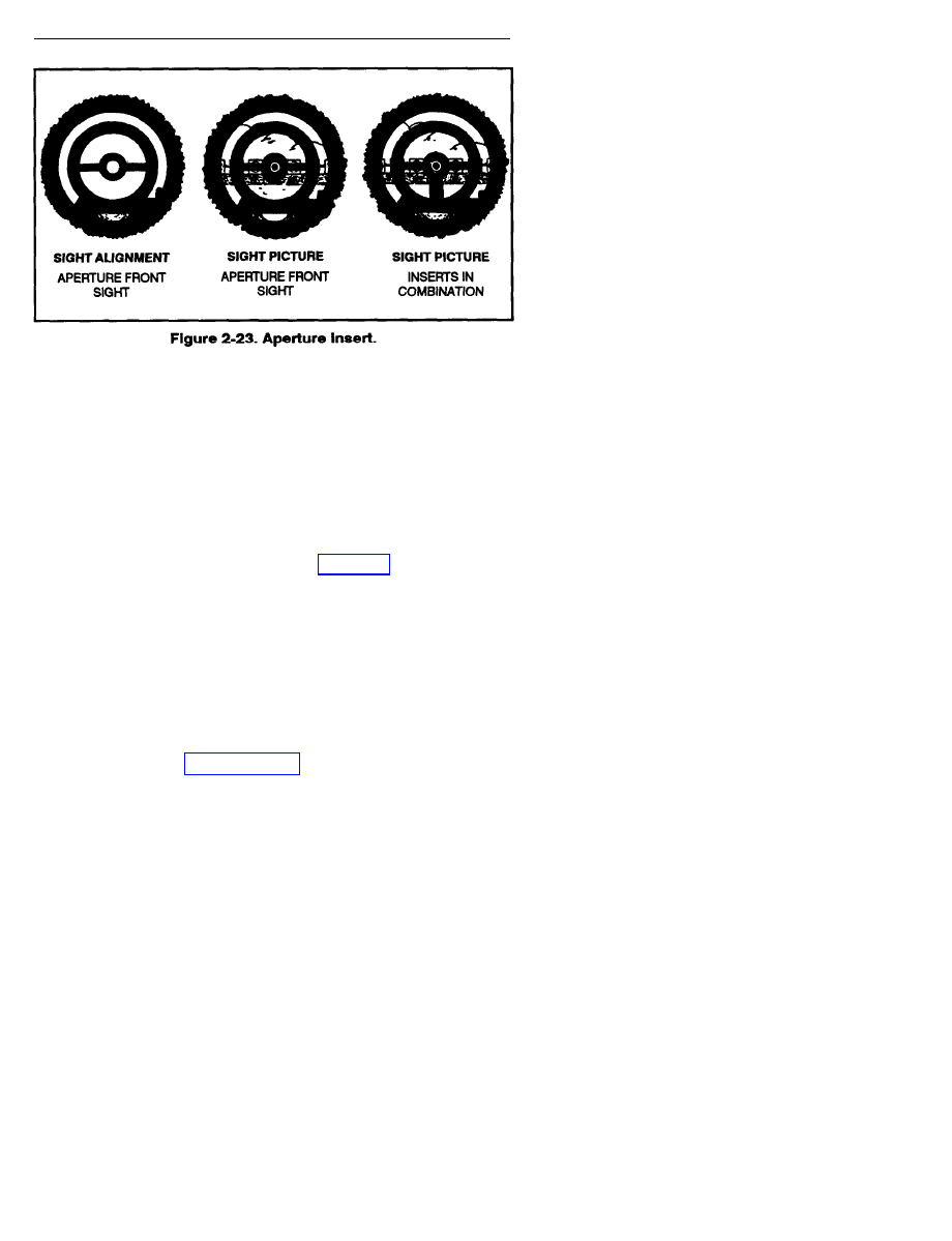
(2) The aperture insert may be either skeleton or translucent plastic
(Figure 2-23, page 2-30). The skeleton aperture is the most widely used.
The translucent plastic aperture is preferred by some shooters and is
available in clear plastic. Both apertures are available in various sizes.
A common error is selecting an aperture that is too small. Select an
aperture that appears to be at least twice the diameter of the bull’s-eye.
An aperture selected under one light condition may, under a different
light, form a halo around the bull or make the bull appear indistinct
or oblong. The aperture selected should reveal a wide line of white
around the bull and allow the bull to standout in clear definition against
this background.
2-29
FM 23-10
(3) Remove one of the three sets of screws from the rear sight base
located on the left rear of the receiver. Align the rear sight with the rear sight
base taking care to use the hole that provides the operator the desired
eye relief. Then tighten the screw to secure the rear sight to the base.
NOTE: Operator-desired eye relief determines the set screw
that must be removed.
b. Adjustment Scales. Adjustment scales are of the vernier type.
Each graduation on the scale inscribed on the sight base equals 3 minutes
of angle. (See the minutes of angle chart in Chapter 3.) Each graduation
of the adjustable scale plates equals 1 minute of angle. To use the
vernier-type adjustment scales—
(1) Note the point at which graduations on both the top and the
bottom scales are aligned.
(2) Count the numbers of full 3 minutes of angle graduations from
“0” on the fixed scale to “0” on the adjustable scale. Add this figure to the
number of 1 minute of angle graduations from “0” on the adjustable scale
to the point where the two graduations are aligned.
c. Zeroing. Zeroing iron sights should be done on the same type of
range and targets as in paragraph 2-10a. To set a mechanical zero on the
iron sights for windage, the sniper turns the windage dial all the way to
the left or right, then he counts the number of clicks it takes to get from
one side to the other. He divides this number by 2—for example,
120 divided by 2 equals 60. The sniper turns the windage dial 60 clicks
2-30
.
FM 23-10
back to the center. If the two zeros on the windage indicator plate do not
align, he loosens the screw on the windage indicator plate and aligns the
two zeros. The sniper uses the same procedure to set a mechanical zero
for elevation. Once a mechanical zero has been set, he assumes a good
prone-supported position, 100 meters from the target. He fires three
rounds at the center of the target, observing the same aiming point
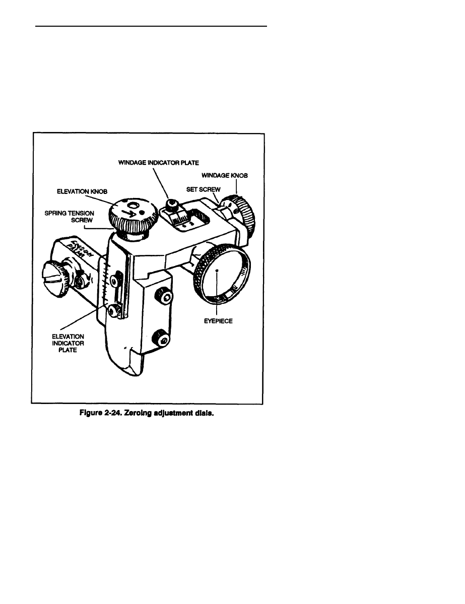
each time. After noting the strike of the rounds, the sniper turns the
elevation and windage dials to make needed adjustments to the iron sights
as follows (Figure 2-24):
2-31

FM 23-10
(1) Each click of adjustment is 1/4 minute of angle (one minute of
angle equals about 1 inch at 100 yards, 6 inches at 600 yards, and so forth).
There are twelve 1/4 minutes of angle, equaling 3 minutes of angle
adjustments in each dial revolution. The total elevation adjustment is
60 minutes of angle (600 inches at 1,000 yards) total windage adjustment
is 36 minutes of angle (360 inches at l,000 yards).
(2) Turn the elevation dial in the direction marked UP to raise the
point of impact: turn the elevation dial in the opposite direction to lower
the point of impact. Turn the windage dial in the direction marked R to
move the point of impact to the right; then turn the windage dial in the
opposite direction to move the point of impact to the left.
(3) Continue firing and adjusting shot groups until the point of aim
or point of impact is achieved.
After zeroing the rifle sight to the preferred range, the sniper loosens the
elevation and windage indicator plate screws with the socket head screw
key provided. Now, he loosens the spring tension screw, aligns the “0” on
the plate with the “0” on the sight body, and retightens the plate screws.
Then the sniper loosens the spring tension screws and set screws in each
dial, and aligns the "0" of the dial with the reference line on the sight.
He presses the dial against the sight, tightens the set screws, and equally
tightens the spring tension screws until a definite "click” can be felt when
the dial is turned. This click can be sharpened or softened to preference
by equally loosening or tightening the spring screws on each dial.
The sniper makes windage and elevation corrections, and returns quickly
to “zero” standard.
Section IV
OTHER EQUIPMENT
The sniper must use special equipment to reduce the possibility of
detection. The types and characteristics are discussed in this section.
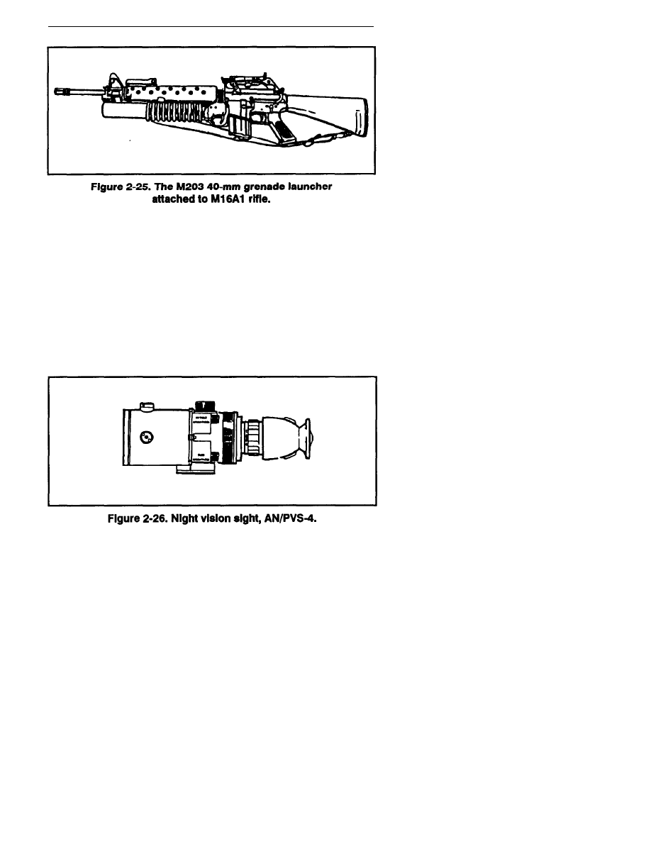
2-12. M16A1/A2 RIFLE WITH M203 GRENADE LAUNCHER
The observer carries the M16A1/A2 rifle with the M203 grenade launcher.
The sniper, carrying the M24 SWS, lacks the firepower required to break
contact with enemy forces-that is, ambush or chance contact.
The rapid-fire ability of the M16A1/A2 rifle, combined with the
destructive abilities of the M203 40-mm grenade launcher (Figure 2-25),
gives the sniper team a lightweight, easily operated way to deliver the
firepower required to break contact. (See FM 23-9 and FM 23-31,
respectively, for the technical characteristics of these weapons.)
2-32
FM 23-10
2-13. IMAGE INTENSIFICATION AND INFRARED DEVICES
The sniper team employs night and limited visibility devices to conduct
continuous operations.
a. Night Vision Sight, AN/PVS-4. The AN/PVS-4 is a portable,
battery-operated, electro-optical instrument that can be hand-held for
visual observation or weapon-mounted for precision fire at night
(Figure 2-26). The observer can detect and resolve distant targets
through the unique capability of the sight to amplify reflected ambient
light (moon, stars, or sky glow). The sight is passive thus, it is free from
enemy detection by visual or electronic means. This sight, with
appropriate weapons adapter bracket, can be mounted on the M16 rifle.
(1) Uses. The M16 rifle with the mounted AN/PVS-4 is effective in
achieving a first-round hit out to and beyond 300 meters, depending on
the light conditions. The AN/PVS-4 is mounted on the M16 since the
2-33

FM 23-10
nightsight’s limited range does not make its use practical for the sniper
weapon system. This avoids problems that may occur when removing and
replacing the sniperscope. The nightsight provides an effective
observation ability during night combat operations. The sight does not
give the width, depth, or clarity of daylight vision; however, a well-trained
operator can see enough to analyze the tactical situation, to detect enemy
targets, and to place effective fire on them. The sniper team uses the
AN/PVS-4 to accomplish the following:
(a) To enhance their night observation capability.
(b) To locate and suppress hostile fire at night.
(c) To deny enemy movement at night.
(d) To demoralize the enemy with effective first-round kills at night.
(2) Employment factors. Since the sight requires target illumination
and does not project its own light source, it will not function in
total darkness. The sight works best on a bright, moonlit night.
When there is no light or the ambient light level is low (such as in heavy
vegetation), the use of artificial or infrared light improves the
sight’s performance.
(a) Fog, smoke, dust, hail, or rain limit the range and decrease the
resolution of the instrument.
(b) The sight does not allow seeing through objects in the field
of view. For example, the operator will experience the same range
restrictions when viewing dense wood lines as he would when using other
optical sights.
(c) The observer may experience eye fatigue when viewing for
prolonged periods. Viewing should be limited to 10 minutes, followed by
a rest period of 10 minutes. After several periods of viewing, he can safely
extend this time limit. To assist in maintaining a continuous viewing.
capability and to reduce eye fatigue, the observer should use one eye then
the other while viewing through the sight.
(3) Zeroing. The operator may zero the sight during daylight or
darkness; however, he may have some difficulty in zeroing just l
before darkness. The light level at dusk is too low to permit the operator
to resolve his zero target with the lens cap cover in place, but it is still
intense enough to cause the sight to automatically turnoff unless the lens
cap cover is in position over the objective lens. The sniper normally zeros
the sight for the maximum practical range that he can be expected to
observe and fire, depending on the level of light.
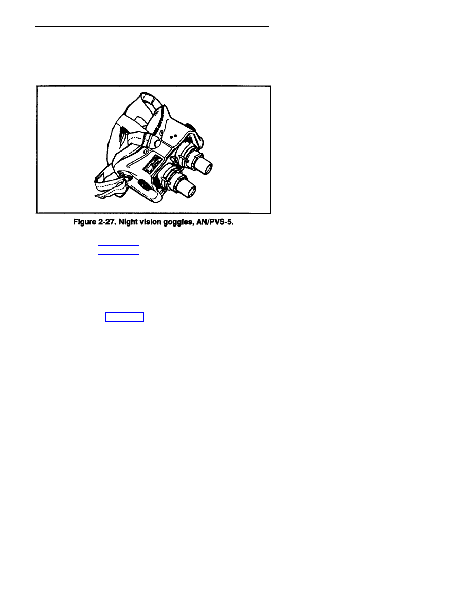
b. Night Vision Goggles,
AN/PVS-5. The
AN/PVS-5 is a lightweight,
passive night vision system that gives the sniper team another means of
2-34
FM 23-10
observing an area during darkness (Figure 2-27). The sniper normally carries
the goggles, because the observer has the M16 mounted with the nightsight.
The goggles make it easier to see due to their design. However, the same
limitations that apply to the nightsight also apply to the goggles.
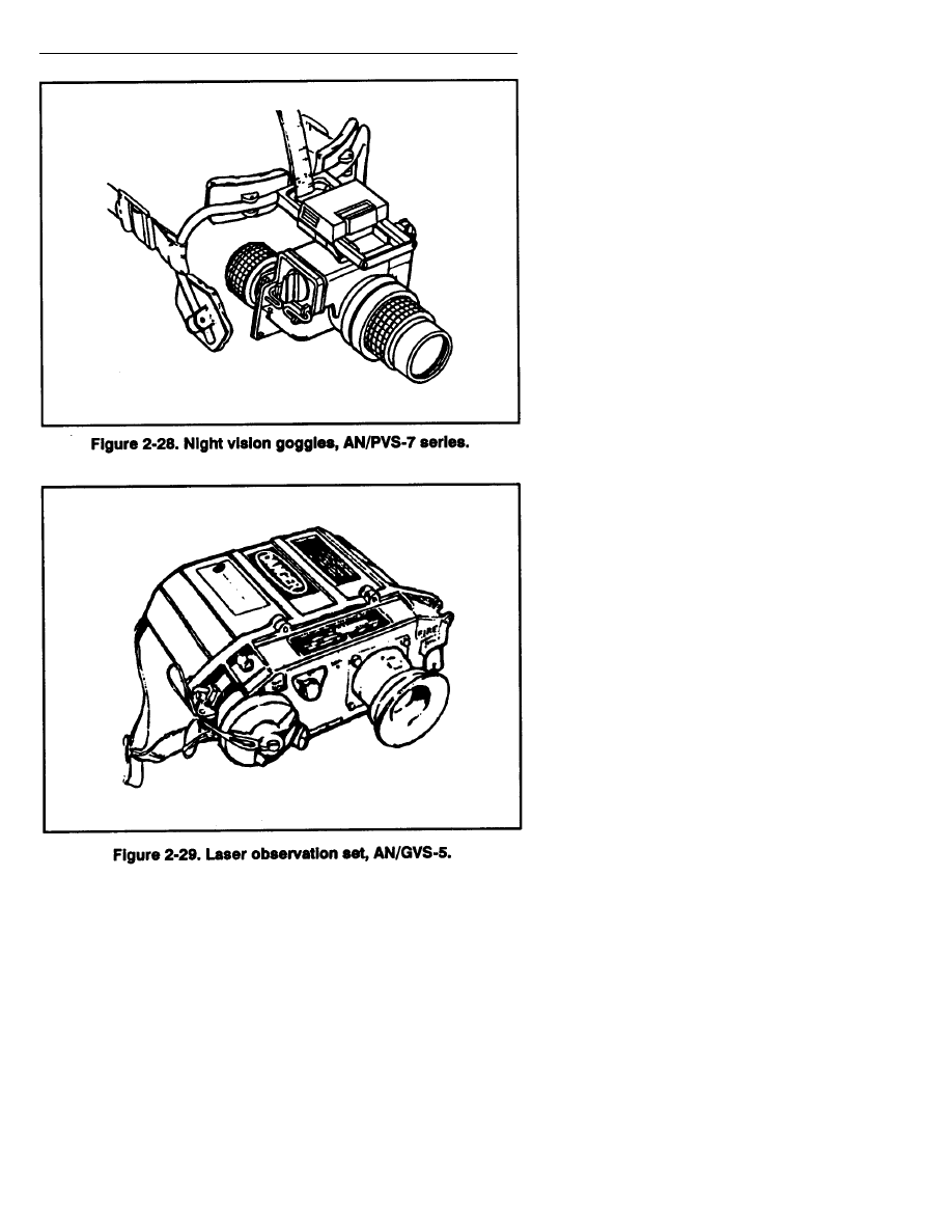
c. Night Vision Goggles, AN/PVS-7 Series. The night vision goggles,
AN/PVS-7 series (Figure 2-28, page 2-36) has a better resolution and
viewing ability than the AN/PVS-5 goggles. The AN/PVS-7 series goggles
have a head-mount assembly that allows them to be mounted in front of
the face so that both hands can be free. The goggles can be used without
the mount assembly for hand-held viewing. (See TM 11-5855-262-10-1.)
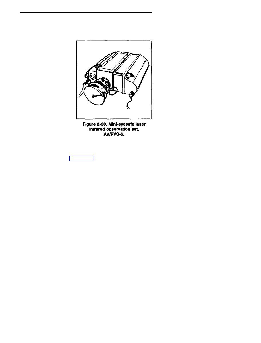
d. Laser Observation Set AN/GVS-5. Depending on the mission,
snipers can use the AN/GVS-5 to determine the range to the target.
The AN/GVS-5 (LR) (Figure 2-29, page 2-36) is an individually operated,
hand-held, distance-measuring device designed for distances from 200 to
9,990 meters (with an error of plus or minus 10 meters). It measures
distances by firing an infrared beam at a target and by measuring the time
the reflected beam takes to return to the operator. It then displays the
target distance, in meters, inside the viewer. The reticle pattern in the
viewer is graduated in 10-mil increments and has display lights to indicate
low battery and multiple target hits. If the beam hits more than one
target, the display gives a reading of the closest target hit. The beam that
is fired from the set poses a safety hazard; therefore, snipers planning to
use this equipment should be thoroughly trained in its safe operation.
(See TM 11-5860-201-10.)
2-35
FM 23-10
2-36
FM 23-10
e. Mini-Eyesafe Laser Infrared Observation Set, AN/PVS-6.
The AN/PVS-6 (Figure 2-30) contains the following components:
mini-eyesafe laser range finder; batteries, BA-6516/U, nonrechargeable,
lithium thionyl chloride;
carrying case; shipping case;
tripod; lens cleaning com-
pound and lens cleaning
tissue; and operator's manual.
The laser range finder is the
major component of the
AN/PVS-6. It is lightweight,
individually operated, and
hand-held or tripod mounted;
it can accurately determine
ranges from 50 to 9,995 meters
in 5-meter increments and
displays the range in the
eyepiece. It can also be
mounted with and bore-
sighted to the night obser-
vation device, AN/TAS-6,
long-range.
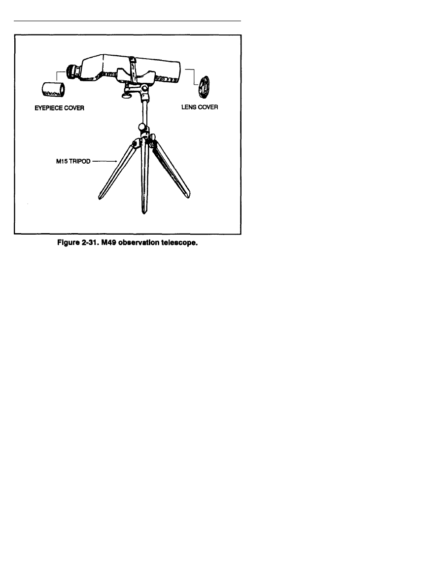
2-14. M49 OBSERVATION TELESCOPE
The M49 observation telescope is a prismatic optical instrument of
20-power magnification (Figure 2-31, page 2-38). The telescope is
focused by turning the eyepiece in or out until the image of the object
being viewed is crisp and clear to the viewer. The sniper team carries the
telescope on all missions. The observer uses the telescope to determine
wind speed and direction by reading mirage, observing the bullet trace,
and observing the bullet impact. The sniper uses this information to
make quick and accurate adjustments for wind conditions. The lens are
coated with a hard film of magnesium fluoride for maximum light
transmission. Its high magnification makes observation, target detection,
and target identification possible where conditions and range would
otherwise preclude this ability. Camouflaged targets and those in deep
shadows can be more readily distinguished. The team can observe troop
movements at greater distances and identify selective targets with ease.
2-37
FM 23-10
a. Components. Components of the telescope include a removable
eyepiece and objective lens covers, an M15 tripod with canvas carrier, and
a hard ease carrier for the telescope.
b. Storage. When storing the M49 observation telescope, the sniper
must remove it from the hard case earner and remove the lens caps to
prevent moisture from gathering on the inside of the scope. Maintenance
consists of—
(1) Wiping dirt and foreign materials from the scope tube, hard case
carrier, and M15 tripod with a damp rag.
(2) Cleaning the M49 lens with lens cleaning solution and lens
tissue only.
(3) Brushing dirt and foreign agents from the M15 carrying case with
a stiff-bristled brush; cleaning the threading of lens caps on the M49 and
the tripod elevation adjustment screw on the M15 with a toothbrush, then
applying a thin coat of grease and moving the lens caps and elevation
adjustment screw back and forth to evenly coat threading.
2-38
FM 23-10
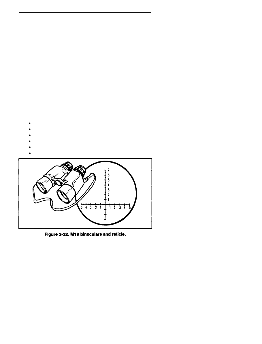
2-15. M19 BINOCULARS
The M19 is the preferred optical instrument for conducting hasty scans.
This binocular (Figure 2-32) has 7-power magnification with a 50-mm
objective lens, and an interpupillary scale located on the hinge. The sniper
should adjust the binocular until one sharp circle appears while looking
through them. After adjusting the binoculars’ interpupillary distance
(distance between a person’s pupils), the sniper should make a mental
note of the reading on this scale for future reference. The eyepieces are
also adjustable. The sniper can adjust one eyepiece at a time by turning
the eyepiece with one hand while placing the palm of the other hand over
the objective lens of the other monocular. While keeping both eyes open,
he adjusts the eyepiece until he can see a crisp, clear view. After one eyepiece
is adjusted, he repeats the procedure with the remaining eyepiece.
The sniper should also make a mental note of the diopter scale reading
on both eyepieces for future reference. One side of the binoculars has a
laminated reticle pattern (Figure 2-32) that consists of a vertical and
horizontal mil scale that is graduated in 10-mil increments. Using this
reticle pattern aids the sniper in determining range and adjusting
indirect-fires. The sniper uses the binoculars for—
Calling for and adjusting indirect fires.
Observing target areas.
Observing enemy movement and positions.
Identifying aircraft.
Improving low-light level viewing.
Estimating range.
2-39
FM 23-10
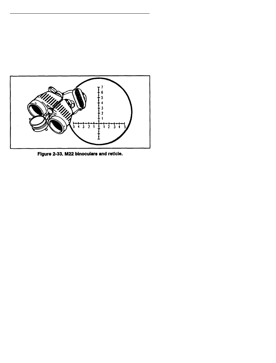
2-16. M22 BINOCULARS
The M22 binoculars (Figure 2-33) can be used instead of the M19.
These binoculars have the same features as the M19, plus fold-down
eyepiece cups for personnel who wear glasses to reduce the distance
between the eyes and the eyepiece. It also has protective covers for the
objective and eyepiece lenses. The binoculars have laser protection filters
on the inside of the objective lenses (direct sunlight can reflect off
these lenses). The reticle pattern (Figure 2-33) is different than the
M19 binocular reticle.
2-17. OTHER SNIPER EQUIPMENT
Other equipment the sniper needs to complete a successful
mission follows:
a. Sidearms. Each member of the team should have a sidearm, such
as an M9, 9-mm Beretta, or a caliber .45 pistol. A sidearm gives a sniper
the needed protection from a nearby threat while on the ground moving
or while in the confines of a sniper position.
b. Compass. Each member of the sniper team must have a lensatic
compass for land navigation.
c. Maps. The team must have military maps of their area
of operations.
d. Calculator. The sniper team needs a pocket-size calculator to
figure distances when using the mil-relation formula. Solar-powered
calculators usually work well, but under low-light conditions, battery
power may be preferred. If a battery-powered calculator is to be used in
low-light conditions, it should have a lighted display.
2-40
FM 23-10
e. Rucksack. The sniper’s rucksack should contain at least a
two-quart canteen, an entrenching tool, a first-aid kit, pruning shears, a
sewing kit with canvas needles and nylon thread, spare netting and garnish,
rations, and personal items as needed. The sniper also carries his ghillie
suit (Chapter 4, paragraph 4-4) in his rucksack until the mission requires
its use.
f. Measuring Tape. A standard 10-foot to 25-foot metal carpenter’s
tape allows the sniper to measure items in his operational area.
This information is recorded in the sniper data book. (See Chapter 4 for
range estimation.)
Section V
COMMUNICATIONS EQUIPMENT
The sniper team must have a man-portable radio that gives the team
secure communications with the units involved in their mission.
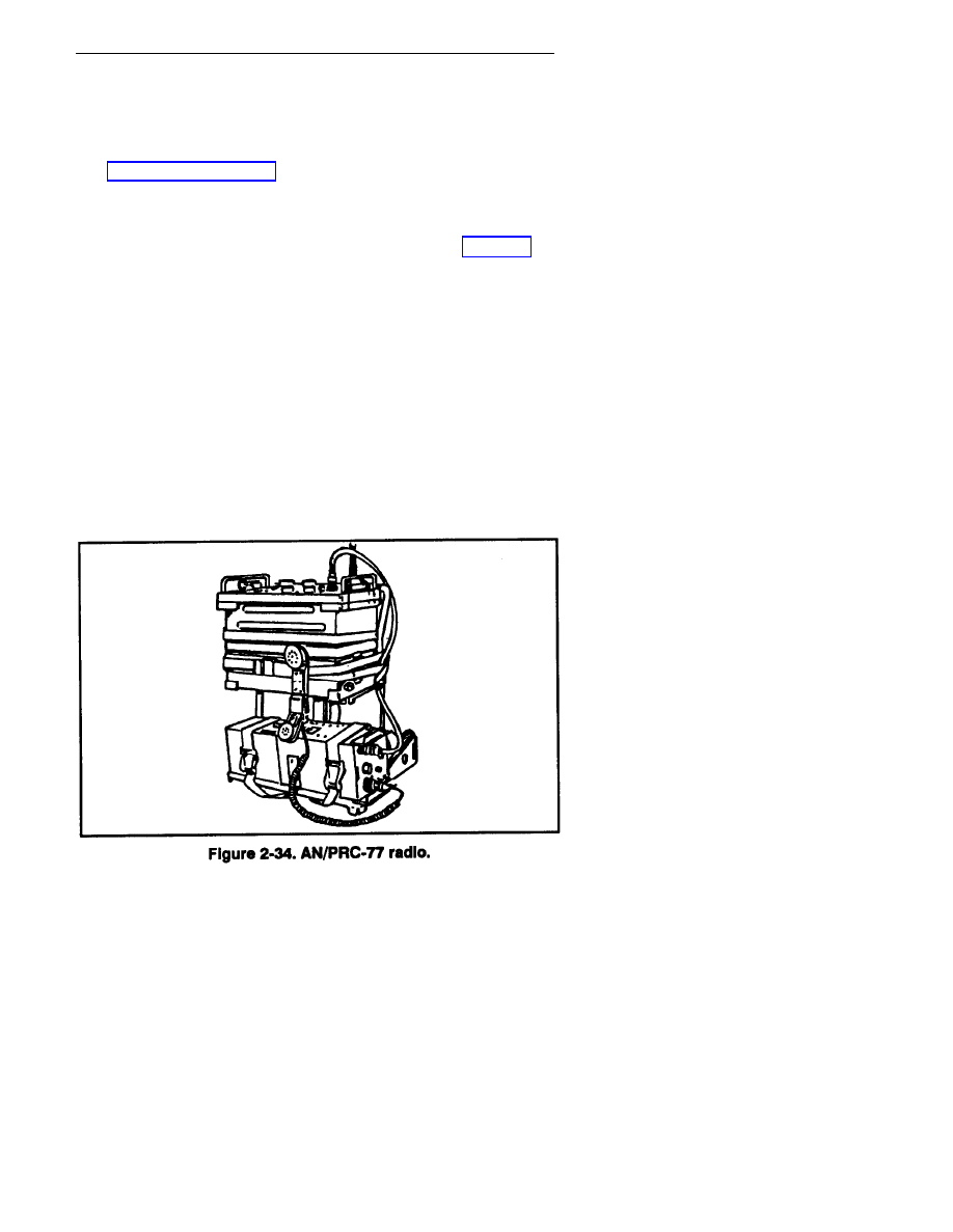
2-18. AN/PRC-77 RADIO
The basic radio for the sniper team is the AN/PRC-77 (Figure 2-34).
This radio is a short-range, man-pack portable, frequency modulated
receiver-transmitter that provides two-way voice communication.
The set can net with all other infantry and artillery FM radio sets on
common frequencies. The AN/KY-57 should be installed with
the AN/PRC-77. This allows the sniper team to communicate securely
with all units supporting or being supported by the sniper team.
2-41
FM 23-10
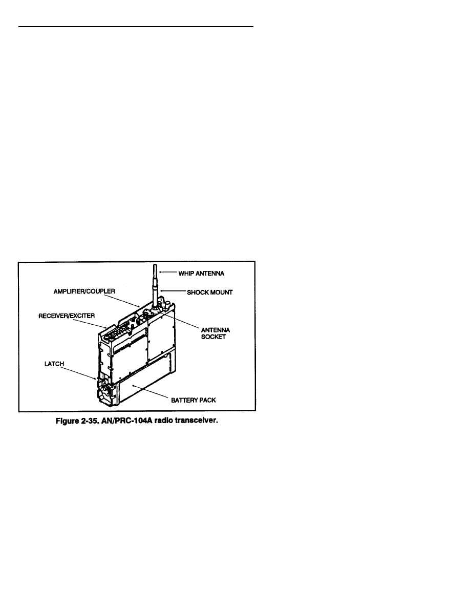
2-19. AN/PRC-104A RADIO TRANSCEIVER
The AN/PRC-104A is a state-of-the-am lightweight radio transceiver that
operates in the high frequency and in the upper part of the low frequency
portions of the radio spectrum (Figure 2-35). The receiver/transmitter
circuits can be tuned to any frequency between 2.0000 and 29.9999 MHz
in 100 Hz increments, making it possible to tune up to 280,000 separate
frequencies. The radio operates in the upper or lower side bank modes
for voice communications, CW for Morse code, or FSK (frequency-shift
keying) for transmission of teletype or other data.
a. In the man-pack configuration, the radio set is carried and operated by
one man or, with the proper accessories, it can be configured for vehicle or
fixed-station use. The radio set with antenna and handset weighs 15.7 pounds.
b. The control panel, human-engineered for ease of operation,
makes it possible to adjust all controls even while wearing heavy gloves.
Unlike older, similar radio sets, there are no front panel meters or
indicator lights on the AN/PRC-104A. All functions that formerly
required these types of indicators are monitored by the radio and
communicated to the operator as special tones in the handset.
This feature is highly useful during tactical blackout operations.
The superior design and innovative features of the AN/PRC-104A radio set
make it possible to maintain a reliable long-range communications link.
The radio uses lightweight, portable equipment that can be operated by
personnel who have minimum training.
2-42
FM 23-10
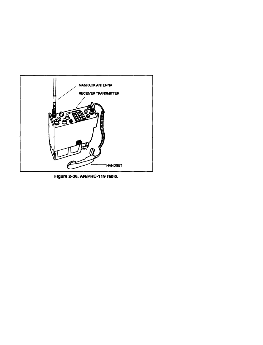
2-20. AN/PRC-119 RADIO
The AN/PRC-119 (Figure 2-36) replaces the AN/PRC-77, although the
AN/PRC-77 is still in use. The AN/PRC-l19 is a man-pack portable,
VHF/FM radio that is designed for simple, quick operation using a
16-element keypad for push-button tuning. It can also be used for
short-range and long-range operation for voice, FSK, or digital
data communications. It can also be used for single-channel operation or
in a jam-resistant, frequency-hopping mode, which can be changed as needed
This radio has a built-in self-test with visual and audio readbacks. It is
compatible with the AN/KY-57 for secure communications.
2-43
Wyszukiwarka
Podobne podstrony:
Ch2 NonConventionalEnergygyandUtilisationResources 2 20 2 22
Ch2 NonConventionalEnergygyandUtilisationResources 2 1 2 16
ch2 53ul5zwpp635kbzi5kvppal6omvvld4g2uo6lmi 53UL5ZWPP635KBZI5KVPPAL6OMVVLD4G2UO6LMI
Ch2 E7
ROZKLAd ch2, Kwantyle c2(p,v) rzędu p rozkładu c2 o
CH2
ch2
Ch2 E3
Ch2 E6
Ch2 E5
fema453 ch2
Ch2 Q1
ch2-chromo, spektro, Chromatografia
Ch2 FuelResourcesFromTheForest
Ch2 E1
ch2 040802
ch2
CH2 (3)
więcej podobnych podstron