
AVR EEPROM Memory Read/Write Cookbook
BETA version 0.00 2/23/08
This is the beta version of a tutorial that, once it has been sufficiently reviewed and
commented in the forum, will be posted in the tutorials section. I’m hoping some folks
will try this out and tell me what wasn’t clear, what didn’t work, and what typos they
found.
AVR EEPROM Memory Read/Write Cookbook
Joe Pardue 2/23/08 beta version 0.00
This ‘tutorial’ is actually a cookbook - by which I mean that I give you proven and tested
recipes for how to use the AVR EEPROM. I use the EEPROM functions from avr-libc
which has it’s own documentation of these functions. Also, I can heartily recommend
Dean Camera’s tutorial on these EEPROM functions which discusses how to use the read
functions: [TUT] [C] Using the EEPROM memory in AVR-GCC
http://www.avrfreaks.net/index.php?name=PNphpBB2&file=viewtopic&t=38417
I felt that this cookbook was needed since neither of the above documents provides
detailed recipes for using the EEPROM functions with real devices.
Introduction to AVR Memory Types
The AVR has EEPROM (Electrically Erasable Programmable Read Only Memory) to
provide users with non-volatile memory for storing data. Technically the Flash Memory
is also electrically erasable and programmable, but it is written and erased in pages [and
is much cheaper than EEPROM which is written and erased in bytes]. While Flash can be
used for non-volatile data storage, you risk trashing your program and AVR Flash is rated
for 10,000 read write cycles (a lot, but not if the data is changed at computer rates), while
the AVR EEPROM is rated at 100,000 read write cycles.
To help get our heads around the meaning of the write/erase cycles think about updating
a bit of data once per hour. You could safely do this for just over 416 days with Flash
Memory, and 4166 days (just under 11 ½ years) with EEPROM. You can see that doing
update every minute would quickly exhaust both memory types (166.6 hours for Flash
and 1666 hours or 69 days for EEPROM).
Flash Memory is intended for occasional updates of program memory or for changing
data at a rate that won’t exhaust the memory within the expected lifetime of the system
you are designing. If you are designing a system to last 10 years, then you could safely
write to a Flash Page 1000 times per year or 2.74 times per day. For the EEPROM we
saw above that hourly writes are permissible.
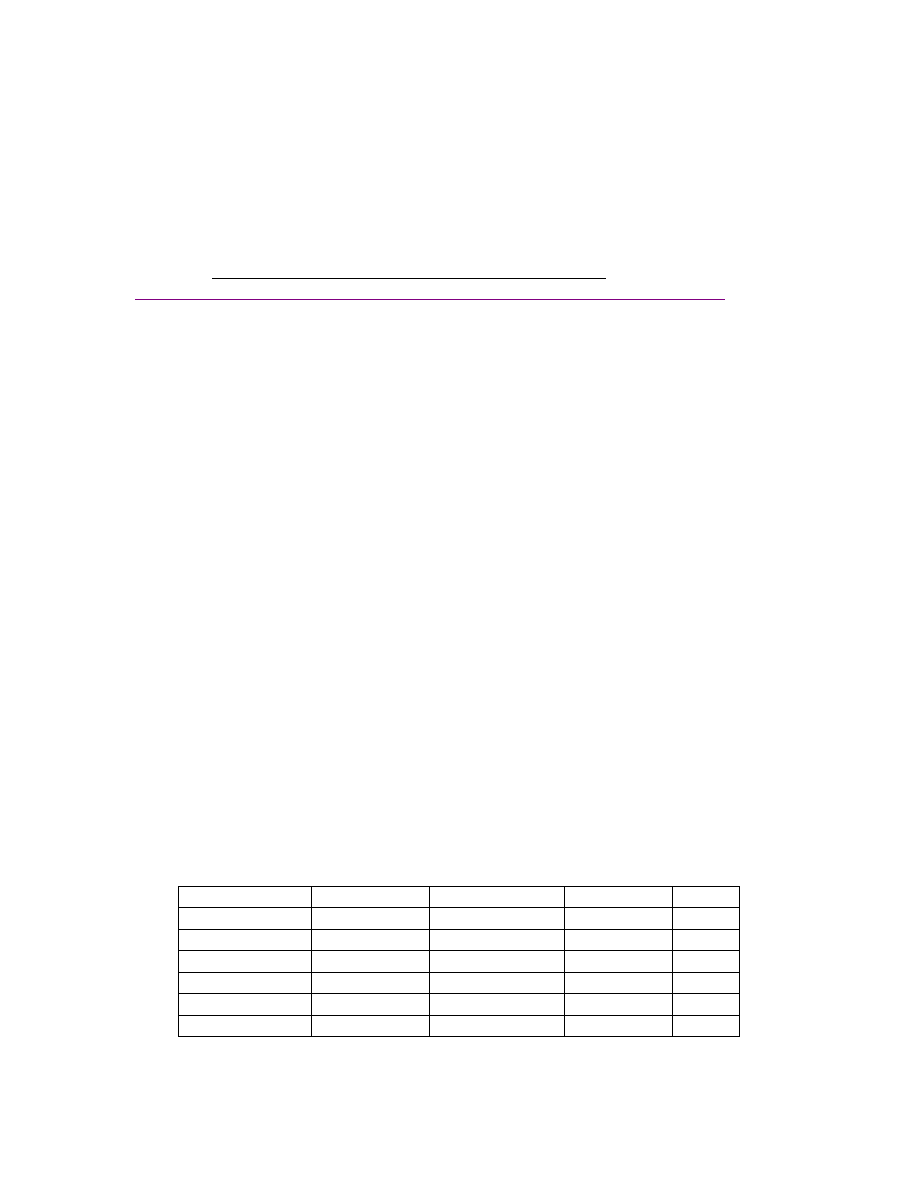
Typical Memory for AVRs:
AVR
SRAM Bytes EEPROM Bytes
Flash Bytes
Cost *
ATmega48 512
256
4096
2.58
ATmega88 1024
512
8192
3.87
ATmega168 1024
512
16384
4.11
ATmega164 1024
512
16384
4.82
ATmega324 2048
1024
32768
6.02
ATmega644 4096
2048
65536
7.87
* Price at DigiKey Jan-April 2008 Catalog – DIP package

EEPROM _Test Software:
WinAVR and AVRStudio
We will be developing the EEPROM_Test software using the WinAVR toolset for the
GCC compiler along with Atmel’s AVRStudio. You can get the latest and greatest
version of WinAVR at:
http://winavr.sourceforge.net
and AVRStudio from
EEPROM _Test is a program written for the ATmega644 and the AVR Butterfly that
allows a PC terminal program, in the case shown here: Smiley Micros Developer
Terminal, to read and write the AVR EEPROM using byte, word, and block functions
from avr-libc (which comes with WinAVR).
We will test this code using the Smiley Micros Developer Terminal and XML files
written to ease the testing process by automatically sending commands and data streams.
You can find the Developer Terminal and the source code for EEPROM_Test at
www.smileymicros.com
downloads menu link: ‘EEPROM Test’.
To simplify things we will keep all the AVR C code and header type information in a
single source code module along with the USART routines.
What we’ll send and what we’ll expect to receive:
Read Byte
Send command byte 0x62 (‘b’)
Send address byte
Receive byte
Write Byte
Send command byte 0x42 (‘B’)
Send address byte
Send byte to write
Read Word
Send command byte 0x77 (‘w’)
Send address high byte
Send address low byte
Receive word high byte
Receive word low byte
Write Word
Send command byte 0x57(‘W’)
Send address high byte
Send address low byte
Send word high byte
Send word low byte
Read Block
Send command byte 0x6b (‘k’)

Send size byte - limit to <= 80
Send EEPROM address start high byte
Send EEPROM address start low byte
Receive number of bytes specified by size
Write Block
Send command byte 0x4b (‘K’)
Send size byte - limit to <= 80
Send EEPROM address start high byte
Send EEPROM address start low byte
EEPROM_Test Source Code:
/*****************************************************
Include and declarations from UART_Test
******************************************************/
#include <avr/io.h>
#include <avr/pgmspace.h>
#include <avr/eeprom.h>
void USART_Init();
void USART_Transmit( unsigned char );
unsigned char USART_Receive( void );
void USART_Transmit_PROGMEM(const char *);
int main(void)
{
uint8_t
c;
uint16_t
Address;
uint8_t
ByteValue;
uint16_t
WordValue;
USART_Init();
while(1)
{
c
=
USART_Receive();
if( c == 'b') // Read Byte
{
Address
=
USART_Receive();
USART_Transmit(eeprom_read_byte((uint8_t*)Address));
}
else if(c == 'B') // Write Byte
{
Address
=
USART_Receive();
ByteValue
=
USART_Receive();
eeprom_busy_wait();
eeprom_write_byte((uint8_t*)Address,ByteValue);
}
else if(c == 'w') // Read Word
{
Address = (USART_Receive() << 8);
Address
|=
USART_Receive();
WordValue
=
eeprom_read_word((uint16_t*)Address);
USART_Transmit(WordValue>>8);
USART_Transmit(WordValue);
}
else if(c == 'W') // Write Word
{

Address = (USART_Receive() << 8);
Address
|=
USART_Receive();
WordValue
=
(uint16_t)(USART_Receive()<<8);
WordValue
|=
(uint16_t)USART_Receive();
eeprom_busy_wait();
eeprom_write_word((uint16_t*)Address,WordValue);
}
else if(c == 'k') // Read Block
{
//NOTE: We are limiting this to 80 bytes for this test
//
this code SHOULD work for the full EEPROM if the
//
array is set to the EEPROM size - not tested though.
uint8_t
LocalBlock[80];
uint16_t
size;
uint16_t
Address;
size = (USART_Receive() << 8);
size
|=
USART_Receive();
Address = (USART_Receive() << 8);
Address
|=
USART_Receive();
// Limit size to 80 due to LocalBlock array size
if(size
>
80)
{
USART_Transmit('?');
break;
}
eeprom_read_block((void*)LocalBlock,(const
void*)Address,size);
int
i;
for(i=0;i<size;i++)
{
USART_Transmit(LocalBlock[i]);
}
}
else if(c == 'K') // Write Block
{
// Receive number of bytes specified by size
// NOTE: We are limiting this to 80 bytes for this test
//
this code SHOULD work for the full EEPROM if the
//
array is set to the EEPROM size - not tested though.
uint8_t
LocalBlock[80];
uint16_t
size;
uint8_t
rec;
uint16_t
Address;
size = (USART_Receive() << 8);
size
|=
USART_Receive();
Address = (USART_Receive() << 8);
Address
|=
USART_Receive();
int i = 0;
for(i = 0; i < size; i++)
{
LocalBlock[i]
=
USART_Receive();
if(i >= 80) break; // Make sure we don't go over 80
}
eeprom_write_block((const
void*)LocalBlock,(void*)Address,size);
}
else
USART_Transmit('?');
}
}
/*****************************************************
Functions from UART_Test

******************************************************/
void USART_Init()
{
/* Set baud rate hard coded to 19200 for 12MHz */
UBRR0L = 38;
/* Enable receiver and transmitter */
UCSR0B = (1<<RXEN0)|(1<<TXEN0);
/* Set frame format: 8data, 2stop bit */
UCSR0C = (1<<USBS0)|(3<<UCSZ00);
}
void USART_Transmit( unsigned char data )
{
/* Wait for empty transmit buffer */
while ( !( UCSR0A & (1<<UDRE0)) )
;
/* Put data into buffer, sends the data */
UDR0 = data;
}
unsigned char USART_Receive( void )
{
/* Wait for data to be received */
while ( !(UCSR0A & (1<<RXC0)) )
;
/* Get and return received data from buffer */
return
UDR0;
}
void USART_Transmit_PROGMEM(const char *FlashString)
{
int i = 0;
// The 'for' logic terminates if the byte is '\0' or if i = 60.
// '\0' is 'null' and terminates C strings
// The 80 prevents too much overrun if we get a bad pointer
// and it limits the string size
for( i = 0 ; pgm_read_byte(&FlashString[i]) && i < 80; i++)
{
USART_Transmit(pgm_read_byte(&FlashString[i]));
}
}
Building Your Hardware Development Platform:
We will be using two different hardware setups, one each for the AVR Butterfly and the
ATmega644.
The Butterfly will be the easiest to use since the hardware is easy to construct and it has a
built-in bootloader allowing us to easily download our test software. However, on the
downside, it uses the RS232 port and if you don’t have one, you’ll need a USB to RS232
converter cable.
The breadboarded ATmega644 will use USB via the BBUSB, but it will also be much
harder to use without errors since it will be programmed on a breadboard using a DIY
ISP connector to an AVR Dragon (you can also use the STK-500 or an AVRISP). I will
frequently warn newbies not to try the breadboarding platform. So, why not now? Hey,
newbies, don’t try this with the breadboard– use the Butterfly++ MiniKit!
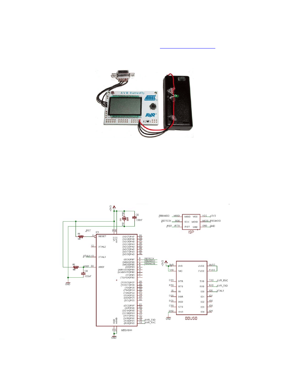
AVR Butterfly Hardware Setup:
I recommend getting the Butterfly++ MiniKit from
has the RS232 connector and a battery case. Also, you can download the Quick Start pdf
file that shows you how to build it and use it, so no need to repeat all that here.
Figure 1: AVR Butterfly++ MiniKit:
Breadboard + ATmega + BBUSB Setup:
Setting up the BBUSB:
Make sure that you have read the BBUSB documentation and that you set up CBUS0 to
output 12MHz.
Schematic using the ATmega44:
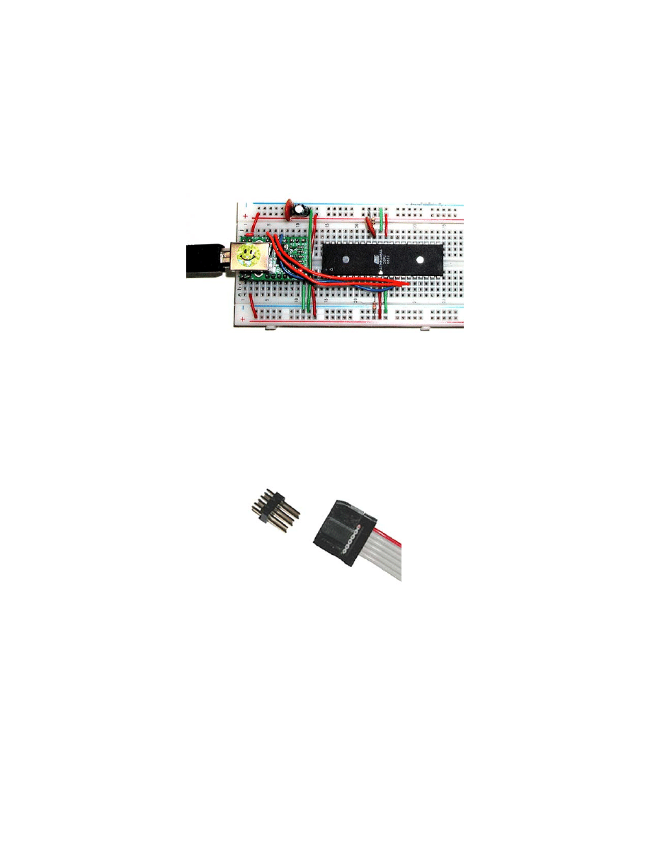
Wire the ATmega644 on the breadboard with the BBUSB:
Piece of cake, right? Well if you think so then you are a better wirer upper than I am
since this took me several tries to get it right. And I had the advantage of using a
ATmega644 preloaded with some code to ping bytes to the Developer Terminal. If you
don’t have a preprogrammed Atmega644, then be even more careful and cross your
fingers. Wiring is shown in Figure 2:
Figure 2: ATmega + BBUSB + Breadboard:
Breadboard DIY ISP Connector for the brave and/or foolhardy:
I made up an ISP connector that works with a breadboard. This was so easy that I only
screwed up maybe a dozen times. I do not recommend this for a newbie, if you aren’t
very overconfident then get another development board like the ones sold by Olimex for
these experiments.
First get either two 3-pin single row headers or one 6-pin dual row header like shown in
Figure 3:
Figure3: Dual 6-pin Header and ISP connecter
Now solder some different colored wires to the header making sure that the wires come
out wing-like so they won’t short circuit each other at the base of the header. See Figure
4:
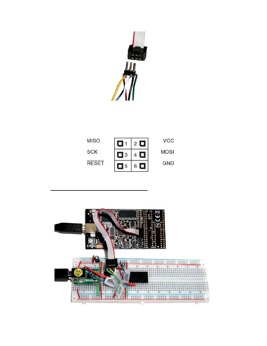
Figure 4: Dual 6-pin Header wires added.
Now you should add some tape flags to each of the wires with the name of the ISP signal
on each leg. The names should conform to the standard 6-pin ISP connector shown in
Figure 5:
Figure 5: ISP Connections
Now CAREFULLY FOLLOWING THE LABELS plug this into your breadboard
conforming to the ATmega pin out. In the case of the ATmega644 as shown in Figure 6:
Figure 6: ISP Connection to ATmega644 on a breadboard:
Shivers are going up my spine at this point imagining all the folks who will screw this up
and blame me – well, it wasn’t easy, but I got it working following exactly this
procedure. I repeat what I said above, if you aren’t overconfident, then use the Butterfly
or some other platform with everything soldered down properly.
Using EEPROM_Test with Smiley Micros Developer Terminal
If you already have the Developer Terminal beta r03 loaded on your system then you will
only need to copy the EEPROM_Test.xml file to the directory containing your Developer
Terminal Executable.
• You will load this XML file by opening the file menu and clicking on the ‘Open
XML Data’ item then select from the directory form the file: ‘EEPROM_Test.xml’.
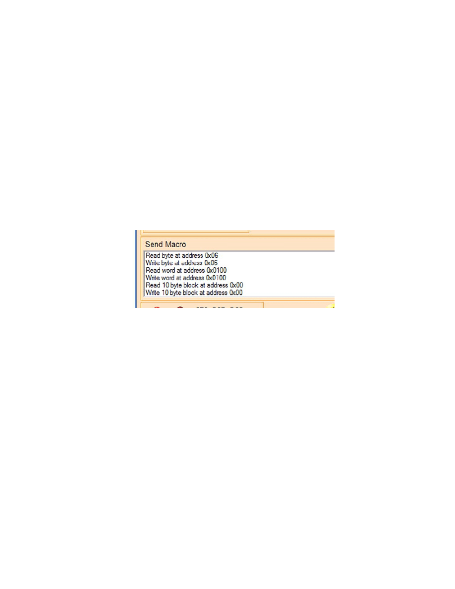
Figure 7 shows the names of the macros we will be using.
Figure 7: Send Macro text box
• Click the ‘Receive as’ HEX option in the Receive Text area.
• In the Send Macro text box, click on the ‘Read byte at address 0x06’. You should see
in the Send text box ‘0x62,0x06’ which is the command ‘b’ for read a byte and the
EEPROM byte address 6. These two bytes are sent to the AVR which, in the unlikely
event that everything goes as it should, will read whatever is at that address and show
it in the Receive text box, probably 0xFF for a virgin ATmega644.
• In the Send Macro text box, click on the ‘Write byte at address 0x06. You should see
‘0x42,0x06,0x55’ which is the byte write command: ‘B’ (0x42), the EEPROM byte
address: 6, and the byte value to write: 0x55.
• In the Send Macro text box, click on the ‘Read byte at address 0x06’. Again, you
should see ‘0x62,0x06’ in the Send Text box. Now you should see 0x55 in the
Receive text box showing that you have successfully written a byte to the EEPROM
and read it back.
• To test the word read/write: in the Send Macro text box, click on the ‘Write word at
address 0x0100. You should see ‘0x57,0x01,0x00,0x11,0x22
,
’ which is the word
write command: ‘W’ (0x57), the EEPROM byte address: 0x0100, and the word value
to write: 0x1122 sent as two bytes: 0x11 and 0x22. See the endians discussion below
to learn about the order of bytes in words.
• In the Send Macro text box, click on the ‘Read word at address 0x0100. You should
see ‘0x77,0x01,0x00,’ which is the word read command: ‘w’ (0x77), and the
EEPROM byte address: 0x0100. You should see 0x11,0x22 in the Receive text box
showing that you have successfully written a word to the EEPROM and read it back.
Note that the word is shown as two bytes, not a word, since the Developer terminal is
written to only handle bytes.
• To test the block read/write: in the Send Macro text box, click on the ‘Write byte
block at address 0x00. You should see ‘0x4B,0x00,0x0A,0x00,0x00,0x01,0x02,0x03,
0x04,0x05,0x06,0x07,0x08,0x09,0x0A,’ which is the block write command: ‘K’
(0x4B), the EEPROM byte address: 0x00, the number of bytes in the block 0x0A, and
the block of ten bytes valued 0x00 to 0x0A.
• In the Send Macro text box, click on the ‘Read byte block at address 0x00. You
should see ‘0x00,0x01,0x02,0x03,0x04,0x05,0x06,0x07,0x08,0x09,0x0A,’ which is
the word read command: ‘w’ (0x77), and the EEPROM byte address: 0x0100. You
should see 0x11,0x22 in the Receive text box showing that you have successfully
written a 10 byte block to the EEPROM and read it back.
You can change the data for these commands by
carefully
editing the
EEPROM_Text.xml file. Save a copy first and note that XML files fail with no error
messages so make you changes carefully.
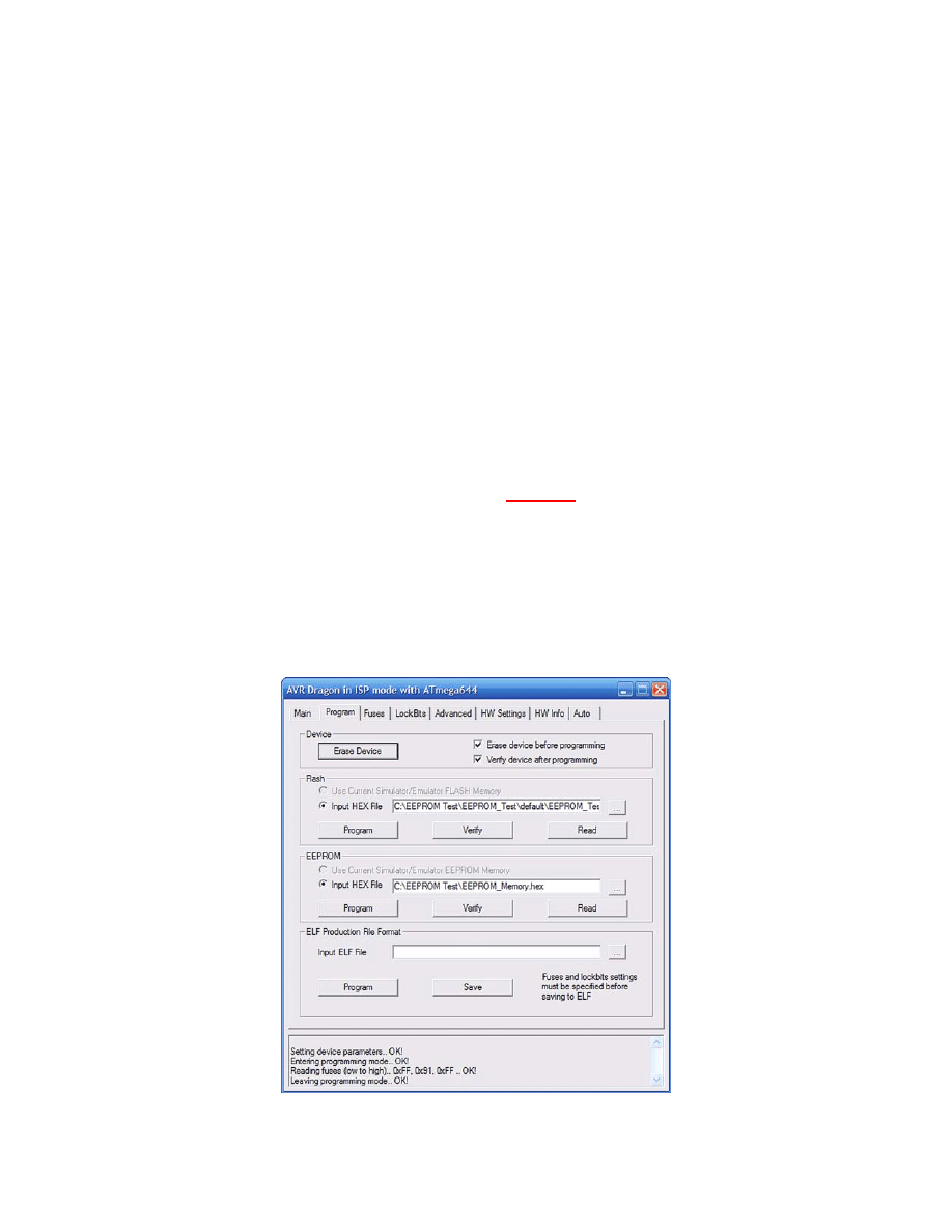
Using AVRProg to view the EEPROM memory
Now just in case you think I’ve written a special version of Developer Terminal that
fakes the demonstration above, I’ll provide some independent verification using
AVRProg for AVRStudio.
Figure 8: Reading the EEPROM memory

• In AVRStudio open the AVRProg utility.
• In the EEPROM section click the ‘Input HEX file’ radio button and browse to a
location to put the EEPROM HEX file you will read.
• Click Read.
• Open the EEPROM_Memory.hex file in NotePad.
• The memory should look like:
:100000000102030405060708090AFFFFFF00FFFFBE
:10001000FFFFFFFFFFFFFFFFFFFFFFFFFFFFFFFFF0
:10002000FFFFFFFFFFFFFFFFFFFFFFFFFFFFFFFFE0
:10003000FFFFFFFFFFFFFFFFFFFFFFFFFFFFFFFFD0
:10004000FFFFFFFFFFFFFFFFFFFFFFFFFFFFFFFFA4
:10005000FFFFFFFFFFFFFFFFFFFFFFFFFFFFFFFFAB
:10006000FFFFFFFFFFFFFFFFFFFFFFFFFFFFFFFFA0
:10007000FFFFFFFFFFFFFFFFFFFFFFFFFFFFFFFF90
:10008000FFFFFFFFFFFFFFFFFFFFFFFFFFFFFFFF80
:10009000FFFFFFFFFFFFFFFFFFFFFFFFFFFFFFFF70
:1000A000FFFFFFFFFFFFFFFFFFFFFFFFFFFFFFFF60
:1000B000FFFFFFFFFFFFFFFFFFFFFFFFFFFFFFFF50
:1000C000FFFFFFFFFFFFFFFFFFFFFFFFFFFFFFFF40
:1000D000FFFFFFFFFFFFFFFFFFFFFFFFFFFFFFFF30
:1000E000FFFFFFFFFFFFFFFFFFFFFFFFFFFFFFFF20
:1000F000FFFFFFFFFFFFFFFFFFFFFFFFFFFFFFFF10
:100100002211FFFFFFFFFFFFFFFFFFFFFFFFFFFFC9
:10011000FFFFFFFFFFFFFFFFFFFFFFFFFFFFFFFFEF
:10012000FFFFFFFFFFFFFFFFFFFFFFFFFFFFFFFFDF
:10013000FFFFFFFFFFFFFFFFFFFFFFFFFFFFFFFFCF
...
OMMITED LINES
...
:1007D000FFFFFFFFFFFFFFFFFFFFFFFFFFFFFFFF29
:1007E000FFFFFFFFFFFFFFFFFFFFFFFFFFFFFFFF19
:1007F000FFFFFFFFFFFFFFFFFFFFFFFFFFFFFFFF09
:00000001FF
You can see the block write of bytres valued 0 to 10 in the first line and you can see the
value of the word write in the first 4 characters of the 0x0100 memory location, but note
that they are shown as: 2211. But… you say, didn’t we write 0x1122? And the answer
follows.
Endians
In case you didn’t know - endian refers to the byte order in a word stored in memory. For
little endian storage, the low byte of the word is stored first, in the lower of the byte
addresses for the word. And big endian is just the opposite. For instance the word 0x1122
if stored little endian will have the 0x22 stored in memory immediately before the 0x11.
The EEPROM functions in avr-libc read and write words as little endians. So now you
know why when you write the word 0x1122 to memory location 0x0100 and then when
you use AVRProg to dump your EEPROM memory to a hex file you’ll see:
:100100002211FFFFFFFFFFFFFFFFFFFFFFFFFFFFC9
That concludes this cookbook tutorial. You can help the AVR learning community by
trying this out and commenting on what wasn’t clear, what didn’t work, and what typos
you found.
Document Outline
Wyszukiwarka
Podobne podstrony:
mb memory ga ma785gt ud3h
Memory
Memory 19 07 (rano)
chirstmas misc memory cards 02
memory pauzy
IMMOAUDI, RENAUL MEGANE HC11 NIEZABEZPIECZONA EEPROM
BMW5, RENAUL MEGANE HC11 NIEZABEZPIECZONA EEPROM
MC68HC705V8 MC68HC705V8 EEPROM Programming Tool ODESSA
06 Memory Related Perils and Pitfalls
Memory prorocy
opis memory
Teoria 1.0, Phase-change memory
Christmas memory game
0 car key memory pl www przeklej pl
E46 Car Key Memory
Bmw Car Key Memory dis
więcej podobnych podstron