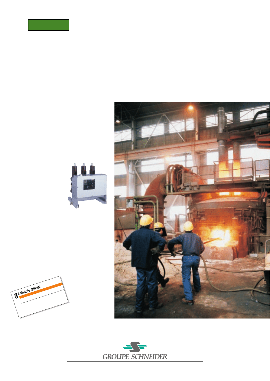
Power supply to electric furnaces
Switch/circuit-breaker
for the control of
heavy duty furnaces
ISF2 :
■
Merlin Gerin
■
Square D
■
Telemecanique
2
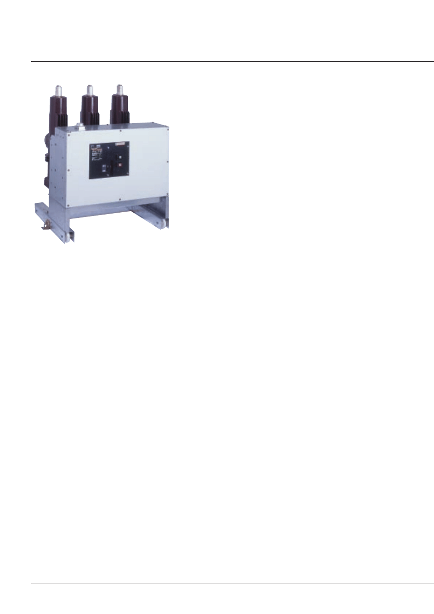
ISF2 switch/circuit-breaker
Description
Application
The ideal technology for electric furnace
control
The ISF2 is a three-phase switch/circuit-breaker for
indoor use based on SF6 technology.
It carries out control of electric furnaces up to 40.5 kV
and complies with IEC standard publications 56 and
694.
Safety
The SF6 breaking technique is especially well suited to making and breaking furnace
currents while avoiding any overvoltages likely to damage equipment on the furnace
supply line.
The ratings, rated current breaking under rated voltage, are held at 0 relative bars.
Each pole-unit, filled to a pressure of 0.15 MPa (i.e. 1.5 relative bars), is fitted with a
safety disk and diagnostic system for continuous monitoring of the SF6 pressure.
Durability suitable for heavy duty
The mechanical durability of the ISF2 is 50,000 mechanical switching operations
with maintenance every 10,000 operations.
Reliability
The mechanical operating mechanism, based on energy storing springs, is a key
feature of the device’s reliability: Schneider has 25 years of experience in these
types of mechanism.
Because Schneider fully masters the design and monitoring of sealing systems,
the device will give you lasting performances throughout its service life.
Environmentally friendly
The ISF2 furnace switch has been designed for environmental protection:
c
the materials used, insulators and conductors, are identified, easy to separate
and recyclable,
c
the SF6 can be recovered at the end of the device service life and reused after
being treated.
Quality
Each switch undergoes systematic routine tests for checking quality and conformity:
c
pole-unit sealing tested,
c
correct mechanical operation of the device tested together with associated locking
systems,
c
simultaneous contact closing tested,
c
power frequency insulation level tested,
c
main circuit resistance tested,
c
auxiliary circuit insulation tested,
c
switching operation speed tested,
c
switching cycle tested,
c
switching operation times tested.
The results obtained are recorded on each device’s test certificate.
The entire switch creation and manufacturing process is quality controlled in
compliance with the French association for quality assurance (AFAQ): ISO 9002
certification. The ISF2 switch has passed type tests in compliance with IEC 56 and
265 standards.
ISF2
ISF2 switch/circuit-breaker
3
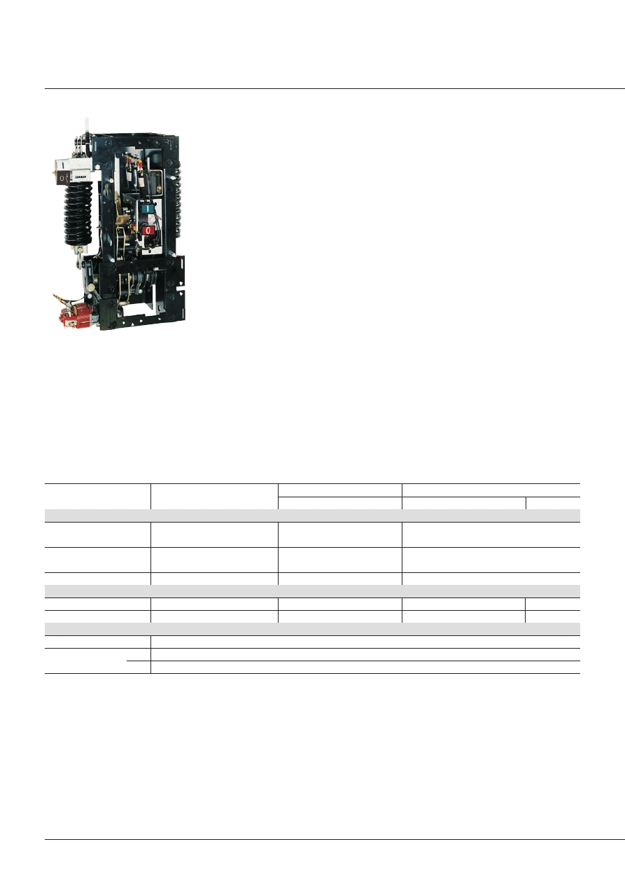
Device description
The ISF2 is a disconnectable fixed device made up of:
c
3 separate pole-units, each being built into a “sealed pressure system” type
insulating enclosure; each pole-unit is filled with SF6 at low pressure (0.15 MPa,
i.e. 1.5 bars),
c
a Gmh type spring stored energy operating mechanism,
c
a front panel with the manual operating mechanism and position indicators,
c
upstream and downstream terminals for power circuit connection,
c
a multipin socket for auxiliary circuit connection,
c
un dispositif d’auto-diagnostic, pour le contrôle permanent du gaz SF6 sur chacun
des 3 pôles, équipé de :
v
1 “low threshold” contact, for possible pressure drop indication,
v
1 “high threshold” contact, for indication of a rise in pressure due to abnormal
overheating of the pole-unit or the arcing contact wear limit being reached.
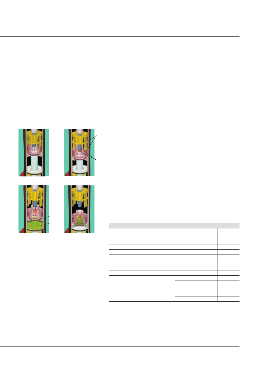
Principle of the breaking technique
auto-compression
This breaking technique has been widely tried and tested and produces high
performances.
The arc is blown and thus extinguished by forced convection.
Fig 1: The circuit-breaker is closed.
Fig 2: When the main contacts open (a), the current is sent into the breaking circuit (b).
Fig 3: When the arcing contacts separate an electric arc appears: this is controlled
by the insulating nozzle; a piston (c) attached to the moving contact moves
downwards and compresses the gas in (d); the gas then escapes via the holes in the
piston into the tubular arcing contact zone, cools down and deionizes the electric arc
zone, thus extinguishing the arc when the current reaches 0 point.
Fig 4: The circuit-breaker is open.
a
b
d
c
Fig 1
Fig 2
Fig 3
Fig 4
Ratings
(1) For voltage of 36 to 40.5 kV, suitable inter-phase barriers supplied with the device must be
installed by the contractor.
CEI 56
rated voltage
kV, 50/60 Hz
24
40.5
(1)
insulation level
r.m.s. kV, 50 Hz - 1 mn
50
85
kV, 1.2/50
µ
s impulse
125
185
(1)
rated current
A
2500
2500
Isc breaking capacity
r.m.s. kA
31.5
25
making capacity
peak kA
79
62.5
allowable short time
r.m.s. kA, 3 s
31.5
25
with stand current
peak kA
79
62.5
rated switching cycle
O - 3 mn - CO - 3 mn - CO
c
c
operating time
ms
opening
45 to 65
45 to 65
breaking
60 to 80
60 to 80
closing
70 to 90
70 to 90
electrical durability
number
time
10
10
total
see curve p.5
see curve p.5
4
ISF2 switch/circuit-breaker
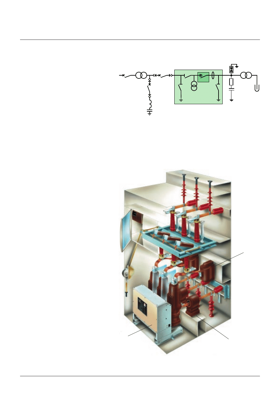
Application example
Simplified diagram
1
2
3
4
5
6
8
7
9
5
11
12
10
13
1
HV circuit-breaker
2
HV/MV step-down transformer
3
Power factor correction device
4
Protective circuit-breaker
5
Earthing switch
6
Isolation switch
7
ISF2 for furnace control
8
Voltage transformer
9
Current transformer
10
Surge arrester
11
RC circuit
12
Furnace MV/LV transformer
13
Furnace electrodes
Schneider offers complete solutions for the power supply to your furnaces:
consult us.
ISF2 mounting in a cubicle
8
9
7
HV MV
MV LV
ISF2 switch/circuit-breaker
5
Maintenance
Life expectancy of pole-units
The stress that the device has to withstand is variable depending on the type of
installation and the operating rules. The life expectancy of the poles is essentially
proportional:
c
to the number of load current making and breaking cycles,
c
to the value of the furnace supply transformer rated current.
Example: for an arc furnace fed by a 100 MVA transformer at 30 kV (or 67 MVA
at 20 kV) with a load cycle of 2000 A, the life expectancy of an ISF2 is 28,000
CO cycles (or 50,000 CO cycles when the set of pole-units is replaced).
Electrical durability
This depends on:
c
the furnace load current,
c
the circuit configuration when the device switches:
v
opening
v
closing
c
the rating of the furnace transformer and in particular of the inrush current during
no-load energization,
c
the elements inserted in the furnace supply line, saturable reactor, non-saturable
reactor, etc.
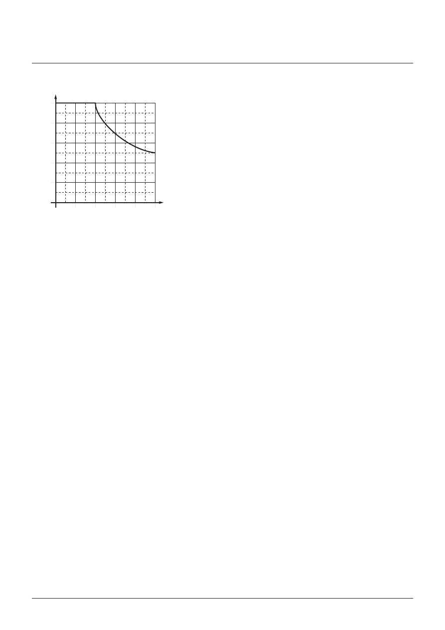
The electrical durability can be estimated using the graph in figure 1 based on the
following operating hypotheses:
1- Protection of overload currents above 2 In is carried out by the circuit-breaker
located upstream.
2 - Switching operations are carried out with the electrodes out of the bath.
3 - The no-load inrush current of the furnace transformers is below 4 In.
cycles
I (A)
0
10000
20000
30000
40000
50000
0
500
1000
1500
2000
2500
Fig 1 - Life expectancy of a set of pole-units (number of
CO cycles) depending on the furnace load current I.
Maintenance
SF6 breaking devices do not generally require special maintenance.
However, since the furnace operating mechanism undergoes heavy stress, it is
advisable to carry out basic maintenace involving the following operations:
c
depending on the ambient environment, clean the surface of the insulating
enclosures;
c
every 10,000 switching operations:
v
measure the wear on the arcing contacts without removing the pole-units during
inspection and maintenance operations (the auto-diagnostic system monitors wear
on the pole-units throughout the device service life);
v
clean the operating mechanism, grease it and check the nuts and bolts.
6
ISF2 switch/circuit-breaker
Gmh stored energy operating mechanism
Operating mechanism
The ISF2 is fitted with a Gmh type operating mechanism based on stored energy
which gives the device a closing and opening speed which is not dependent on the
operator.
The GMh operating mechanism is made up of:
c
a stored energy mechanism which stores the energy required for device closing
and then opening in springs;
c
a manual charging mechanism using a removable lever;
c
an electrical charging mechanism with a motor which automatically recharges the
operating mechanism as soon as the device is closed;
c
a mechanical “opening-closing” mechanism actuated by 2 pushbuttons located on
the front panel;
c
an electrical “closing” mechanism including:
v
1 closing release for remote control,
v
1 anti-pumping relay;
c
an electrical “opening”system, including 1 shunt opening release; an optional
undervoltage release can be added to this device;
c
a mechanical position indicator with “white-black” or “red-green” mechanical
indicators;
c
a switching operations counter.
c
A 14 strong auxiliary contact block including:
v
2 contacts for the electrical operating mechanism,
v
1 contact for the shunt release,
v
11 available contacts;
c
1 closing contact for “operating mechanism charged” indication;
c
1 “open” position key-lock support (lock supplied);
c
a multipin connector (male and female) with 36 pins and a 2 metre lead.
Gmh operating mechanism
Operating mechanism low voltage auxiliaries
charging motor
closing release
(1)
opening release
M
YF
YO1, YO2
YM
supply voltages
AC (V)
50 - 110 - 127 - 220
50 - 110 - 127 - 220
50 - 110 - 127 - 220
50 HZ
AC (V)
120 - 240
120 - 240
120 - 240
60 HZ
DC (V)
(2)
24 - 48 - 60 - 110 - 127 - 230
24 - 48 - 60 - 110 - 127 - 230
24 - 48 - 60 - 110 - 127 - 230
consumption
AC
700 VA
120 VA
120 VA
100 VA
DC
570 W
70 W
70 W
10 W
Auxiliary contacts
rated current
10 A
breaking capacity
CA
10 A at 220 V (cos
ϕ
<i 0.3)
CC
3 A at 110 ou 220 V (L/R <i 0.01 s)
(1) With anti-pumping relay.
(2) For other values, please consult us.
ISF2 switch/circuit-breaker
7
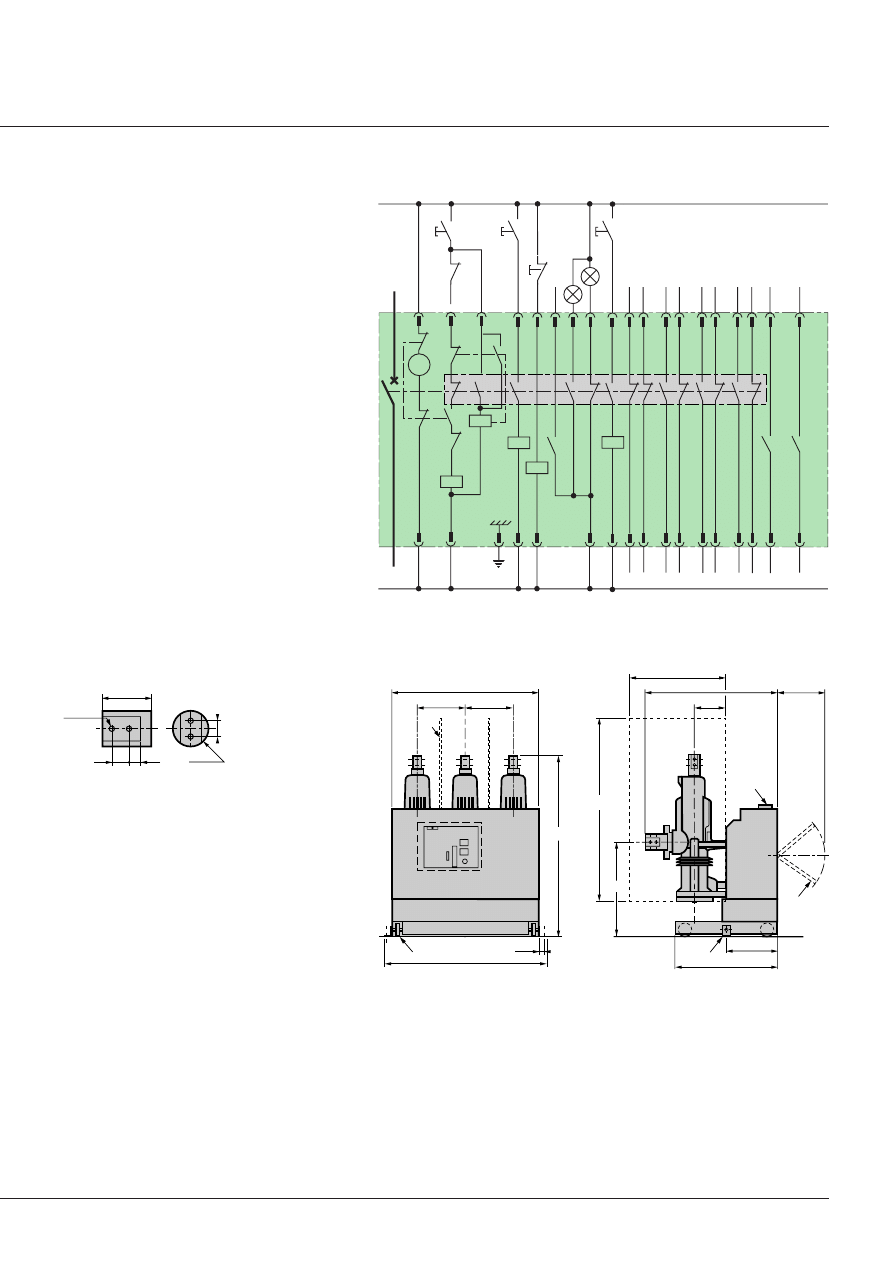
Operating mechanism wiring diagram
J
Circuit-breaker.
KN
Anti-pumping relay.
M
Charging motor.
M1-M2
End-of-charging limit switches.
M3
“Operating mechanism charged” contact.
QF
Circuit-breaker auxiliary contacts.
SE
Trip hold contact.
Sm1
Closing pushbutton (external).
Sm2-Sm4
Opening pushbuton for shunt
release(external).
Sm3
Opening pushbutton for undervoltage
release (external).
Sn
Closing disable contact (external).
SP1-SP2
Pressure switch contacts.
YF
Closing release.
Y01-Y02
Shunt opening release.
YM
Undervoltage release.
Sm2
Sm3
M3
KN
Y01
YM
SP1
SP2
Sm1
Sn
M2
SE
YF
J
M1
M1
M
QF
Y02
Sm4
Dimensions and weights
a: fixing lugs supplied on the frame are used to anchor the device to the ground;
b: the device is fitted with rollers to facilitate handling and installation;
c: multipin connector;
d: inter-phase barriers delivered with the 40.5 kV version;
e: removable charging lever.
Approximate weight: 194 kg
300
300
1108
630
736
190
300
1010
644
910
322
35
690
1060
a
e
c
d
b
Connection pad:
2 Ø 14
Ø 60
30
30
20
78
ISF2 switch/circuit-breaker
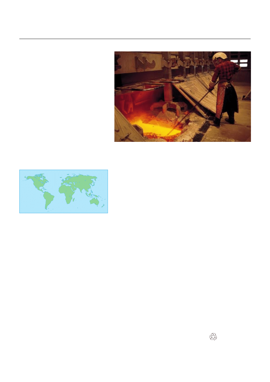
1
A few furnace switch references
c
Cockerill Sambre - 156 MVA - Belgium
c
Baotou - 150 MVA - China
c
Betasteel - 100 MVA - United States
c
Ascometal - 90 MVA - France
c
Usinor - 55 MVA - France
c
Sollac - 85 MVA - France
c
United Steel Mill - 85 MVA - Israel
c
ILSA - 120 MVA - Mexico
c
Taleras - 38 MVA - Mexico
c
Aceros DMSA de CV - 35 MVA - Mexico
c
Huta Batory - 156 MVA - Poland
c
Yamato - 96 MVA - Thailand
Schneider Electric SA
Postal address
F-38050 Grenoble cedex 9
tel : +33 (0)4 76 57 60 60
telex : merge 320842 F
As standards, specifications and designs change from time to
time, please ask for confirmation of the information given in this
publication.
Design and production: AXESS (07)
Printing:
AMTED397053EN
ART.78659
02 / 1998
This document has been
printed on ecological paper.
Document Outline
Wyszukiwarka
Podobne podstrony:
04 SF CIRCUIT BREAKERS
PKZM4XTPR…DC1 motor protective circuit breaker
Circuit Breakers
Motor protective circuit breaker PKZM0XTPR…BC1
Motor protective circuit breaker PKZM0XTPR…BC1
fuses and circuit breakers
PKZM PKZM4XTPR…DC1 motor protective circuit breaker MN03402002Z DE EN
INNE Circuit Breaker Test Device h1585dgb
Circuit Breakers
circuit cellar1996 04
circuit cellar1991 04,05
circuit cellar2001 04
circuit cellar2002 04
circuit cellar1995 04
circuit cellar1994 04
circuit cellar2004 04
circuit cellar1992 04,05
więcej podobnych podstron