
Funktionsprüfgerät
Circuit Breaker Test Device
IZM-XTEST
Bed
ie
nung
shand
buch
Moeller GmbH
Industrieautomation
Hein-Moeller-Straße 7–11
D-53115 Bonn
E-Mail: info@moeller.net
Internet: www.moeller.net
© 2002 by Moeller GmbH
Änderungen vorbehalten
AWB1230-1585D+GB xx/xx/Ki 03/06
Printed in the Federal Republic of Germany (0x/02)
Article No.: xxxxxx
4 *patpks#nycmyn*
Bedienungsanleitung
Operating Manual
03/06 AWB1230-1585D+GB
A
A
A
Think future. Switch to green.
Think future. Switch to green.
Rü
cken
brei
te
b
is 10
mm (
1
Bl
a
tt = 0,106 mm
, gilt
n
u
r für XBS)

Alle Marken- und Produktnamen sind Warenzeichen oder
eingetragene Warenzeichen der jeweiligen Titelhalter.
1. Auflage 2006, Redaktionsdatum 03/06,
© Moeller GmbH, 53105 Bonn
Autor:
Klaus Grül
Produktion: Michael Kämper
Alle Rechte, auch die der Übersetzung, vorbehalten.
Kein Teil dieses Handbuches darf in irgendeiner Form
(Druck, Fotokopie, Mikrofilm oder einem anderen Verfahren)
ohne schriftliche Zustimmung der Firma Moeller GmbH, Bonn,
reproduziert oder unter Verwendung elektronischer Systeme
verarbeitet, vervielfältigt oder verbreitet werden.
Änderungen vorbehalten.
All brand and product names are trademarks or registered
trademarks of the owner concerned.
1
st
published 2006, edition date 03/06
© Moeller GmbH, 53105 Bonn
Author:
Klaus Grül
Production: Michael Kämper
All rights reserved, including those of the translation.
No part of this manual may be reproduced in any form
(printed, photocopy, microfilm or any other process) or processed,
duplicated or distributed by means of electronic systems without
written permission of Moeller GmbH, Bonn.
Subject to alteration without notice.
Rü
cken
brei
te
f
e
stl
e
g
e
n! (
1
Bl
att = 0,
10
6 mm,
gi
lt
n
u
r für XBS)
Note
These instructions do not purport to cover all details or variations in
equipment, nor to provide for every possible contingency to be met
in connection with installation, operation or maintenance.
Should further information be desired or should particular problems
arise which are not covered sufficiently for the Purchaser’s purpo-
ses, the matter should be referred to the local
Moeller
Sales
Office.
The contents of these oerating instructions shall not become part of
or modify any prior or existing agreement, commitment or relati-
onship. The sales contract contains the entire obligations of
Moel
-
ler
. The warranty contained in the contract between the parties
is the sole warranty of
Moeller
. Any statements contained herein
do not create new warranties or modify the existing warranty.
Symbols
Hinweis
Diese Bedienungsanleitung enthält aus Gründen der Übersichtlich-
keit nicht sämtliche Detailinformationen zu allen Typen des Pro-
dukts und kann auch nicht jeden denkbaren Fall der Aufstellung,
des Betriebes oder der Instandhaltung berücksichtigen.
Sollten Sie weitere Informationen wünschen, oder sollten beson-
dere Probleme auftreten, die in der Bedienungsanleitung nicht aus-
führlich genug behandelt werden, können Sie die erforderliche
Auskunft über die örtliche
Moeller
-Niederlassung anfordern.
Außerdem weisen wir darauf hin, dass der Inhalt dieser Bedie-
nungsanleitung nicht Teil einer früheren oder bestehenden Verein-
barung, Zusage oder eines Rechtsverhältnisses ist oder dieses
abändern soll. Sämtliche Verpflichtungen von
Moeller
ergeben
sich aus dem jeweiligen Kaufvertrag, der auch die vollständige und
alleingültige Gewährleistungsregelung enthält. Diese vertraglichen
Gewährleistungsbestimmungen werden durch die Ausführung die-
ser Bedienungsanleitung weder erweitert noch beschränkt.
Symbole
Warnhinwei
s
Warning
CE-Zeiche
n
CE identification

I
Inhalt
1
Lieferumfang
1-1
2
Technische Daten
2-1
3
Verwendung
3-1
4
Beschreibung der Bedienelemente
4-1
5
Bedienung
5-1
5.1 Zeitmessung
5-1
5.2 Bedienung des Prüfgerätes
5-1
5.3 Einstellen der Prüfströme L1, L2, L3 und N
5-2
5.4 Simulation des Stromes eines externen
Erdschlusswandlers (GF CT)
5-2
6
Prüfung des einstellbaren Überlastauslösers (L)
6-1
6.1 Prüfung des Grenzstromes
6-1
Unterer Grenzwert (1.05 x
I
R
)
6-1
Oberer Grenzwert (1.3 x
I
R
)
6-1
6.2 Überprüfung der Überlast Kennlinie (L)
6-1
6.3 Prüfung des Trägheitsgrades
6-2
6.4 Prüfung des thermischen Gedächtnisses
6-2
7
Prüfung des kurzzeitverzögerten
Kurzschlussauslösers (S)
7-1
7.1 Prüfung des Ansprechstromes
7-1
Unterer Grenzwert
7-1
Oberer Grenzwert
7-1
7.2 Prüfung der Verzögerungszeit
7-2
Stromunabhängige Verzögerung, t
sd
= fix
7-2
I
²t
sd
-abhängige Verzögerung
7-2
Zeitverkürzte Selektivitätssteuerung "ZS
I
"
7-3
Auslösung ohne Sperrsignal (am ZS
I
-Modul)
7-3
Auslösung mit Sperrsignal (am ZS
I
-Modul)
7-3
8
Prüfung des unverzögerten Kurzschlussauslösers (
I
) 8-1
8.1 Prüfung des Ansprechstromes
8-1
Unterer Grenzwert
8-1
Oberer Grenzwert
8-1
8.2 Prüfung der Auslösezeit
8-1
9
Prüfung des Erdschlussauslösers (G)
9-1
9.1 Prüfung des Ansprechstromes bei der Messmethode
„Vektorielle Summenbildung“
9-1
Unterer Grenzwert
9-1
Oberer Grenzwert
9-1
Prüfung der Verzögerungszeit
9-1
Stromunabhängige Verzögerung, t
g
= fix
9-1
I
²t
g
-abhängige Verzögerung
9-2
Zeitverkürzte Selektivitätssteuerung "ZS
I
"
9-2
Auslösung ohne Sperrsignal (am ZS
I
-Modul)
9-2
Auslösung mit Sperrsignal (am ZS
I
-Modul)
9-2
9.2 Prüfung der Erdschlussauslösung bei Anschluss
eines externen Erdschlussstromwandlers,
Messmethode „Direkte Messung des Erdschlussstromes“ 9-3
Unterer Grenzwert
9-3
Oberer Grenzwert
9-3
Prüfung der Verzögerungszeit
9-3
Stromunabhängige Verzögerung, t
g
= fix
9-3
I
²t
g
-abhängige Verzögerung
9-4
Zeitverkürzte Selektivitätssteuerung "ZS
I
"
9-4
Auslösung ohne Sperrsignal (am ZS
I
-Modul)
9-4
Auslösung mit Sperrsignal (am ZS
I
-Modul)
9-4
10 Prüfung der Meldefunktionen
10-1
11 Prüfung des Auslösemagneten
11-1
Contents
1
Scope of Supply
1-1
2
Technical Data
2-1
3
Application
3-1
4
Description of the Control Elements
4-1
5
Operation
5-1
5.1 Time Measurement
5-1
5.2 Operating the Circuit Breaker Test Device
5-1
5.3 Setting the Test Currents L1, L2, L3 and N
5-2
5.4 Simulation of the Current of an External Ground-fault
Current Transformer (GF CT)
5-2
6
Testing the Adjustable Overload Release (L)
6-1
6.1 Testing the Limiting Overload Current
6-1
Lower limit value (1.05 x
I
R
)
6-1
Upper limit value (1.3 x
I
R
)
6-1
6.2 Testing the Overload Characteristic Curve (L)
6-1
6.3 Testing the Time Lag Class
6-2
6.4 Testing the Thermal Memory
6-2
7
Testing the Short-time-delay
Short-circuit Release (S)
7-1
7.1 Testing the Tripping Current
7-1
Lower limit value
7-1
Upper limit value
7-1
7.2 Testing the Delay Time
7-2
Current-independent Delay, t
sd
= fixed
7-2
I
²t
sd
dependent delay
7-2
Zone Selective Interlocking “ZSI”
7-3
Tripping without a Blocking Signal (on ZSI Module)
7-3
Tripping with a Blocking Signal (on ZSI Module)
7-3
8
Testing the Instantaneous Short-circuit Release (
I
)
8-1
8.1 Testing the Tripping Current
8-1
Lower limit value
8-1
Upper limit value
8-1
8.2 Testing the Tripping Time
8-1
9
Testing the Ground-fault Release (G)
9-1
9.1 Testing the Tripping Current when using the
“Vectorial Summation” measuring method
9-1
Lower limit value
9-1
Upper Limit Value
9-1
Testing the Delay Time
9-1
Current-independent Delay, t
g
= fixed
9-1
I
²t
g
Dependent Delay
9-2
Zone Selective Interlocking “ZSI”
9-2
Tripping without a Blocking Signal (on ZSI Module)
9-2
Tripping with a Blocking Signal (on ZSI Module)
9-2
9.2 Testing the Ground-fault Release when an
External Ground-fault Current Transformer is
Connected using the Measuring Method
“Direct Measurement of the Ground-fault Current”
9-3
Lower Limit Value
9-3
Upper Limit Value
9-3
Testing the Delay Time
9-3
Current-independent delay, t
g
= fixed
9-3
I
²t
g
Dependent Delay
9-4
Zone Selective Interlocking “ZSI”
9-4
Tripping without a Blocking Signal (on ZSI Module)
9-4
Tripping with a Blocking Signal (on ZSI Module)
9-4
10 Testing the Signaling Functions
10-1
11 Testing the Tripping Solenoid
11-1

II
12 Abkürzungen
12-1
13 Index
13-1
12 Abbreviations
12-1
13 Index
13-1
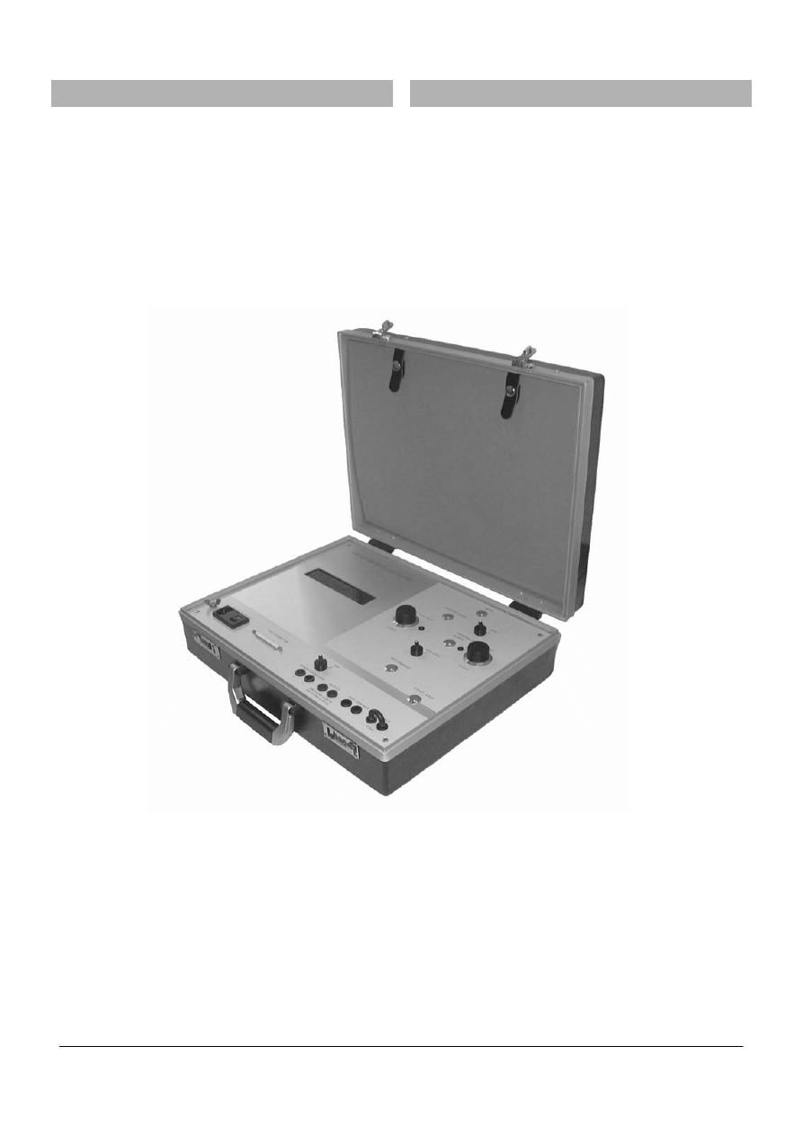
1 Lieferumfang
1 Scope of Supply
•
Funktionsprüfgerät
•
Circuit breaker test device
1 - 1
•
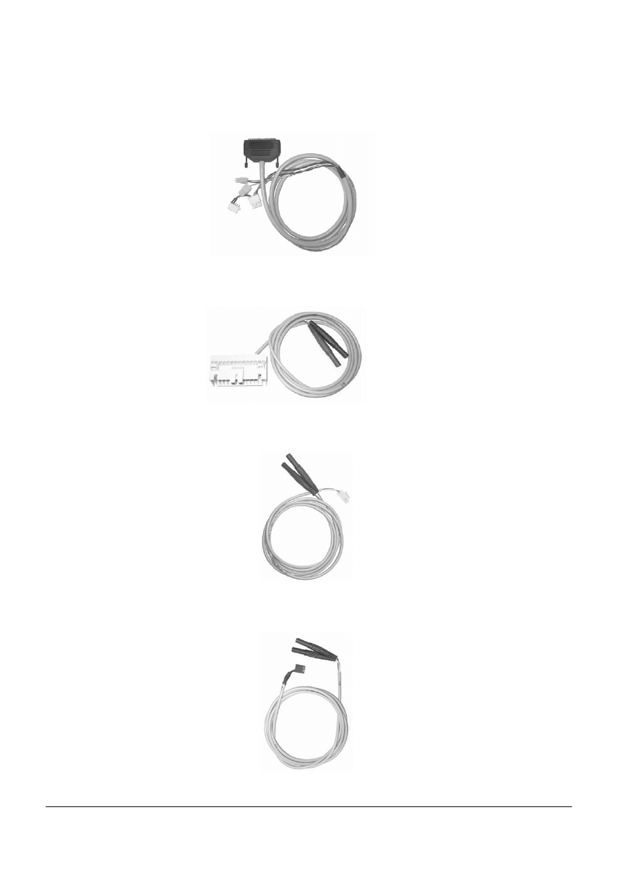
Prüfleitung für „Anschluss des XZM an Prüfgerät“ <A>
•
Test cable for „Connecting the XZM to the circuit
breaker test device“ <A>
• Prüfleitung für „Ausgelöst-Meldung durch internen
Hilfsstromschalter S2“ <B>
• Prüfleiung für „24-V-Versorgung über Hilfsstrom-
stecker –X8“ <C>
• Test cable for „Tripped signal via S2 internal auxiliary
switch“ <B>
• Test cable for „24 V supply via –X8 auxiliary plug
connector“ <C>
•
Prüfleitung für „Ausgelöst-Meldung durch XZM“ <D>
•
Test cable for „Tripped signal via XZM“ <D>
•
Prüfleitung für „24-V-Versorgung des XZM über
Steckverbinder –X27“ <E>
•
Test cable for „24V XZM supply via –X27 plug-in
connector“ <E>
1 - 2

• Netzanschlussleitung <F>
•
Power supply cord <F>
1 - 3
• Bedienungsanleitung AWB 1230-1585D+GB
• Operating instructions AWB 1230-1585D+GB

2 – 1
2
Technical Data
Operating voltage
100 ... 240 V AC 50/60 Hz
Power consumption
85 VA
Dimensions
460 x 360 x 135
Weight
7 kg
Working position
horizontal
2
Technische Daten
Betriebsspannung
100 ... 240 V AC 50/60 Hz
Leistungsaufnahme
85 VA
Abmessungen
460 x 360 x 135
Gewicht
7 kg
Gebrauchslage
waagerecht

3 – 1
3
Application
The
IZM-XPF
circuit breaker test device is used to
test the functions of the
IZM
low-voltage circuit breaker.
For the
XZMA, XZMV, XZMV+XT, XZMU, XZMR
and
XZMD
overcurrent releases of the
IZM
circuit breaker, the circuit
breaker test device can be used to:
• Measure the operating currents and tripping times.
• Check the protection functions for the three phases and
the neutral conductor.
• Verify the function of the tripping solenoid.
• Check the function of the ground-fault protection.
• Measure the opening time of the circuit breaker and to
• Check the trip causes.
The circuit breaker test device generates either a one or two-phase
test voltage that reproduces the output signal of the current sensors
(Rogowski coils). The test voltage is fed into the incoming circuit of
the current measuring device (L1, L2, L3 and N) as either one-
phase or two-phase (180° phase shift) voltage. The level of the
simulated test current is infinitely variable from zero to 150 kA in
four ranges.
Note: A two-phase test voltage infeed is required if the ground fault
release is not deactivated.
The setting range of the test current allows the characteristic curves
of all electronic overcurrent releases (
XZM
) to
be checked.
Therefore, the device does not normally require the
settings
of the electronic overcurrent releases to be altered.
This circuit breaker test device is equipped with a display for setting
the required test current.
The circuit breaker test device takes the frequency dependency of
the test voltage of 50 and 60 Hz appliances into consideration. The
tripping and opening times are also indicated on the test device
display. For carrying out the tests, the overcurrent release can either
be mounted in the circuit breaker or, in special cases, it can be
tested separately. However, the release has to be mounted in the
circuit breaker for testing the tripping solenoid and the opening
times of the circuit breaker.
3
Verwendung
Das Prüfgerät
IZM-XPF
dient zur Überprüfung der
Funktionen des Niederspannungsleistungsschalters
IZM
.
Mit dem Funktionsprüfgerät können bei den Elektronischen Über-
stromauslösern
XZMA
,
XZMV
,
XZMV+XT
,
XZMU
,
XZMR
und
XZMD
des Leistungsschalters
IZM
• Ansprechströme und Auslösezeiten gemessen werden.
• die Schutzfunktionen für die drei Phasen und den Neutral-
leiter überprüft werden.
• die Funktion des Auslösemagneten nachgewiesen wer-
den.
• die Erdschlussschutzfunktion geprüft werden.
• die Öffnungszeit des Leistungsschalters gemessen wer-
den und die
• Auslösegründe überprüft werden.
Das Prüfgerät erzeugt wahlweise eine ein- oder zweiphasige Prüf-
spannung, die das Ausgangssignal der Stromsensoren (Rogowski-
Spulen) nachbildet. Die Prüfspannung wird über die Prüfbuchse
wahlweise in die Eingangskreise der Stromerfassung (L1, L2, L3
und N) ein- oder zweiphasig (180° Phasenverschiebung) einge-
speist. Die Höhe des simulierten Prüfstromes ist von Null bis 150 kA
in vier Bereichen stufenlos einstellbar.
Hinweis: Eine zweiphasige Einspeisung der Prüfspannungen ist
erforderlich, wenn der Erdschlussauslöser nicht deaktiviert ist.
Der Einstellbereich des Prüfstromes erlaubt die Überprüfung aller
Kennlinienfelder der Elektronischen Überstromauslöser (
XZM
).
Das Gerät verlangt daher im Allgemeinen keine Veränderung
der Einstellungen der elektronischen Überstromauslöser.
Das Prüfgerät enthält ein Display zur Einstellung des erforderlichen
Prüfstromes.
Das Gerät berücksichtigt die Frequenzabhängigkeit der Prüfspan-
nung bei 50- und 60-Hz-Anwendungen. Die Auslöse- bzw. Öff-
nungszeiten werden ebenfalls auf dem Display des Prüfgerätes
angezeigt. Für die Prüfungen kann der Überstromauslöser entwe-
der im Leistungsschalter eingebaut sein oder in Sonderfällen sepa-
rat geprüft werden. Nur für die Prüfung des Auslösemagneten und
der Öffnungszeit des Leistungsschalters muss der Auslöser im Lei-
stungsschalter eingebaut sein.
ACHTUNG
NOTICE
Zur Ereichung der angegebenen Genauigkeiten ist eine Vor-
wärmzeit von 15 Minuten erforderlich.
15 preheating is necessary, in order to ensure the specified
exactitudes.
4 – 1
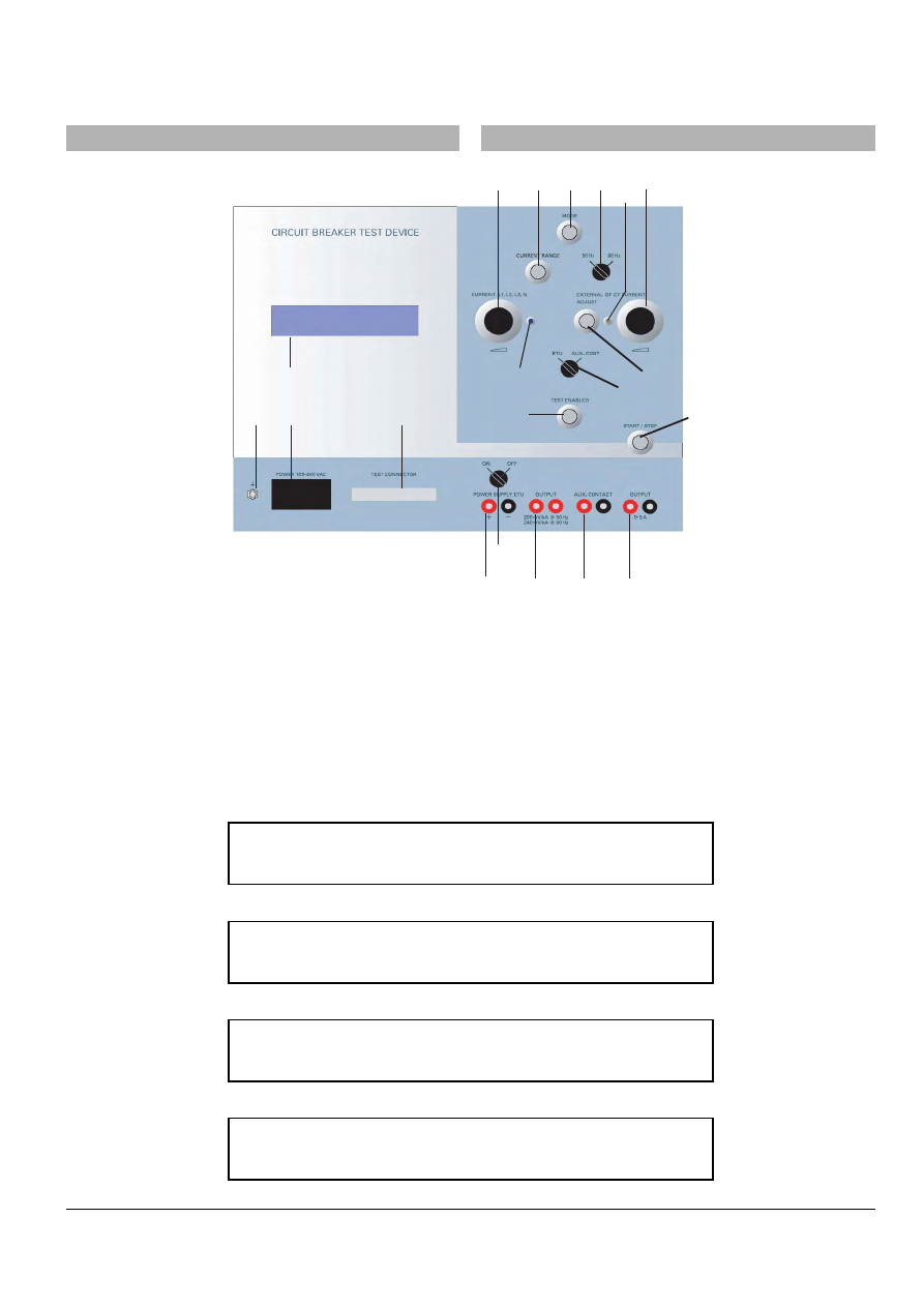
4
Description of the Control Elements
(1) MODE: Selection of phase(s) to be tested, including simulation of an
external ground-fault current transformer
(2) CURRENT RANGE pushbutton 0...150 kA: Test current range
selection from 0 to 150 kA
(3) Selector switch for 50/60 Hz
(4) External GF CT current: External ground-fault current setting
(5) CURRENT L1, L2, L3 and N: Test current setting
(6) Display for indicating the test mode (phase and status), the level of
the test current, and the measured tripping time:
Initial state:
Test enabled:
Test started:
Test finished:
4
Beschreibung der Bedienelemente
(1) MODE: Anwahl der zu prüfenden Phasen(n) einschließlich Simula-
tion eines externen Erdschluss-Strom-Wandlers
(2) CURRENT RANGE Taster 0...150 kA: Bereichswahl des Prüfstro-
mes von 0 bis 150 kA
(3) Wahlschalter für 50/60 Hz
(4) External GF CT Current: Einstellung des externen Erdschlussstro-
mes
(5) CURRENT L1, L2, L3 und N: Einstellung des Prüfstromes
(6) Display zur Anzeige des Prüfmodus (Phase und Status), der Höhe
des Prüfstromes und der gemessenen Auslösezeit:
Ausgangszustand:
Test vorbereitet:
Test gestartet:
Test beendet:
5
4
20
3
1
2
10
7
8
9
19
18
16
17
6
15
11
12
13
14
[ t e s t m o d e ]
[ s t a t u s ]
L 1
0 - 0 , 1 5 k A
T E S T S E T U P
[ c u r r e n t ]
[ t i m e ]
0 , 1 3 k A
[ t e s t m o d e ]
[ s t a t u s ]
L 1
0 - 0 , 1 5 k A
T E S T E N A B L E D
[ c u r r e n t ]
[ t i m e ]
0 , 1 3 k A
[ t e s t m o d e ]
[ s t a t u s ]
L 1
0 - 0 , 1 5 k A
T E S T S T A R T E D
[ c u r r e n t ]
[ t i m e ]
0 , 1 3 k A
0 0 : 0 0 : 1 3
[ t e s t m o d e ]
[ s t a t u s ]
L 1
0 - 0 , 1 5 k A
T E S T F I N I S H E D
[ c u r r e n t ]
[ t i m e ]
0 , 1 3 k A
0 0 : 0 1 : 5 3 , 5 6 2
4 – 2
Test abgebrochen:
(7) ADJUST Taster zur Einstellung des simulierten Erdschlussstromes
eines externen Stromwandlers
(8) ETU / AUX. CONT Schalter zur Anwahl der Betriebsart Auslöse-
impuls
(XZM)
oder Hilfsschalter
(9) TEST ENABLED Taster zur Freigabe der Prüfspannung(en) und
-ströme
(10)START/STOP Taster zur Einleitung einer Prüfung
(11)POWER SUPPLY
ETU
Laborbuchsen 4 mm für die Versorgung der
XZM
mit 24 V DC
(12)OUTPUT Laborbuchsen 4 mm zur Überprüfung der Prüfspannung
L1, L2, L3 und N mit einem Digitalmultimeter
(13)AUX. CONTACT Laborbuchsen 4 mm für die Messung der Auslöse-
zeit
(14)OUTPUT Laborbuchsen 4 mm zur Überprüfung des
Prüfstromes (G) mit einem Digitalmultimeter
(15)ON/OFF Schalter zum Zuschalter der 24 V DC Hilfsspannungsver-
sorgung de
s
XZM
(16)TEST CONNECTOR SUB D Buchse zum Anschluss der Prüfleitung
(17)POWER 100-240 V AC Kaltgerätestecker für den Netzanschluss
des Prüfgerätes
(18)[Erdungssymbol] M6 Schraube für eine zusätzliche Erdung des
Prüfgerätes
(19)LED zur Anzeige der Betriebsart Spannungseinprägung (Simulation
der Rogowski-Spannungen)
(20)LED zur Anzeige der Betriebsart Stromeinprägung (Simulation des
Sekundärstromes eines externen Erdschlussstromwandlers)
Das Prüfgerät ist mit einem Weitbereichs-Schaltnetzteil ausgerüstet
und kann von 100 V bis 240 V AC eingesetzt werden.
Nach Einschalten des Schalters "Power 100-240 V AC" wird die
Betriebsbereitschaft durch das Aufleuchten des Displays angezeigt
.
Zur Überprüfung des elektronischen Überstromauslösers ist die
Ausgangsbuchse "Test Connector" (16) mit der mitgelieferten Lei-
tung <A> mit den Buchsen auf der Rückseite des Überstromauslö-
sers zu verbinden. Dazu ist das Bedienpult des Leistungsschalters
zu entfernen, der elektronische Überstromauslöser aus dem Schal-
ter herauszunehmen und die Prüfleitung an die Buchsen X20, X21
und ggf. X24 anzuschließen. Anschließend ist der Auslöser wieder
in den Schalter einzusetzen. Dazu ist die Bedienungsanleitung des
Leistungsschalters
IZM
zu beachten (Kapitel 9.1.1
3
).
Bestell
bezeichnung
der IZM
Bedienungsanleitung
AWB1230-1407D
Im Anschluss ist eine Überprüfung der Stromwandler des
Leistungsschalters
IZM
mittels Handprüfgerät
IZM-XPH
durchzuführen.
WARNUNG
WARNING
Die Warnhinweise in der Bedienungsanleitung
des Schalters sind unbedingt zu beachten!
Leistungsschalter ausschalten!
Anlage freischalten!
Externe Hilfsspannungen abschalten!
The warnings in the circuit breaker operating
instructions must be observed!
Switch off circuit breaker!
Isolate system!
Switch off external auxiliary voltages!
[ t e s t m o d e ]
[ s t a t u s ]
L 1
0 - 0 , 1 5 k A
T E S T A B O R T E D
[ c u r r e n t ]
[ t i m e ]
0 , 1 3 k A
0 0 : 0 0 : 4 3
Test aborted:
(7) ADJUST pushbutton for setting the simulated ground-fault current of
an external current transformer
(8) ETU / AUX. CONT switch for selecting the operating mode tripping
impulse
(XZM)
or auxiliary switch
(9) TEST ENABLED pushbutton for releasing the test voltage(s) and
currents
(10)START/STOP pushbutton for initiating a test
(11)POWER SUPPLY
ETU
4 mm laboratory sockets for 24 V DC supply
to the
XZM
(12)OUTPUT 4 mm laboratory sockets for checking the test voltage L1,
L2, L3 and N with a digital multimeter
(13)AUX. CONTACT 4 mm laboratory sockets for measuring the
tripping time
(14)OUTPUT 4 mm laboratory sockets for checking the test current (G)
with a digital multimeter
(15)ON/OFF switch for 24 V DC auxiliary voltage supply to the
XZM
(16)TEST CONNECTOR SUB D socket for connecting the test cable
(17)POWER 100-240 V AC connector for non-heating appliances for
providing the circuit breaker test device with power
(18)[Grounding symbol] M6 screw for additional test device grounding
(19)LED for indicating the operating mode voltage memory (simulation
of Rogowski voltages)
(20)LED for indicating the operating mode voltage memory (simulation
of the secondary current of an external ground-fault current
transformer)
The circuit breaker test device is equipped with a wide-range
switched-mode power supply unit, and can be implemented for
voltages ranging from 100 V to 240 V AC.
After switching on the “Power 100-240 V AC” switch, the display will
indicate operation readiness.
To test the electronic overcurrent release, connect the output socket
“Test Connector” (16) to the sockets on the rear of the overcurrent
release by means of the cable provided <A>. For this purpose, the
front panel of the circuit breaker has to be removed, the electronic
overcurrent release has to be removed from the circuit breaker, and
the test cable has to be connected to the X20, X21 and, if applica-
ble, X24 sockets. The release should then be remounted in the cir-
cuit breaker. The operating instructions for the
IZM
circuit breaker
must be observed (Chapter 9.1.1
3
).
IZM operating instructions type designation AWB1230-1407GB
Subsequently, the current transformer of the
IZM
circuit
breaker is to be checked using the
IZM-XPH
hand-
held test device.

5 – 1
5
Operation
5.1
Time Measurement
The time can be measured in two different ways:
(a) By measuring the opening time of the circuit breaker (the time
span from the start of the overcurrent up to the moment the
main and auxiliary current contacts of the circuit breaker open).
To do so, connect the AUX.CONTACT (13) sockets of the circuit
breaker test device to the -X6.3 and -X6.4 auxiliary terminal
block (auxiliary switch -S2 “NO”) of the circuit breaker by means
of the cable provided <B>. A potential difference of up to 240 V
AC/DC between the auxiliary switch contacts is permissible.
(b) By measuring the tripping times of the overcurrent release (the
time span from the start of the overcurrent up until the moment
the tripping signal of the electronics is issued). To do so, remove
the connection for the tripping solenoid from the -X22 socket
and plug in the -X22 plug of the test cable <D> into the -X22
socket on the back of the release.
Connect the 4 mm laboratory plugs of the test cable <D> to the
AUX.CONTACT (13) sockets of the circuit breaker test device.
The overcurrent release of communications-capable circuit
breakers with
XZMU, XZMR
and
XZMD
can be activated by
means of 24 V DC voltage. To do so, connect the sockets of the
circuit breaker test device (15) and the -X8.3 (plus) and -X8.4
(ground) auxiliary terminal block of the circuit breaker by means of
the cable provided <C>.
5.2
Operating the Circuit Breaker Test Device
1
If required, connect the circuit breaker test device to PE
potential by means of the grounding screw.
2
Connect the circuit breaker test device to the circuit breaker
by means of the provided test cable <A>.
3
Connect the power supply cord <F> to the circuit breaker
test device and to the power supply.
4
Connect the time measurement cable <B> to the -X6
terminal on the circuit breaker and the AUX. CONTACT
sockets (13) on the circuit breaker test device.
5
If required, connect the 24 V DC external voltage supply
cable <C> to the -X8 auxiliary terminal of the circuit breaker
and to the POWERSUPPLY ETU sockets (11).
6
Switch on the circuit breaker test device by means of the
power switch (17).
7
After switching on, the circuit breaker test device will
automatically be in setup mode, phase L1.
8
Select the desired current range of the test current with the
CURRENT RANGE (2) 0...150 kA pushbutton.
9
Set the desired test current in kA by means of the
CURRENT L1, L2, L3, N potentiometer (5).
10 Enable testing by pressing the TEST ENABLED
pushbutton (9).
11 Begin testing by pressing the START/STOP
pushbutton (10).
5
Bedienung
5.1
Zeitmessung
Die Zeitmessung kann auf zwei Arten erfolgen:
(a) Messung der Öffnungszeit des Leistungsschalters (Zeit vom
Beginn des Überstromes bis zur Kontaktöffnung der Haupt- und
Hilfsstromkontakte des Leistungsschalters). Dazu sind die
Buchsen AUX.CONTACT (13) des Prüfgerätes mit Hilfe der mit-
gelieferten Leitung <B> mit dem Hilfsklemmenblock -X6.3 und
-X6.4 (Hilfsschalter -S2 "NO") des Leistungsschalters zu verbin-
den. Ein Potentialunterschied zwischen den Hilfsschalterkontak-
ten bis 240 V AC/DC ist zulässig.
(b) Messung der Auslösezeit des Überstromauslösers (Zeit vom
Beginn des Überstromes bis zum Auslösesignal der Elektronik).
Dazu ist der Anschluss des Auslösemagneten aus der Buchse
-X22 zu entfernen und der Stecker -X22 an der Prüfleitung <D>
in die Buchse -X22 auf der Rückseite des Auslösers zu stecken.
Die Laborstecker 4 mm der Prüfleitung <D> werden mit den
Buchsen AUX.CONTACT (13) des Prüfgerätes verbunden.
Der Überstromauslöser kommunikationsfähiger Leistungsschalter
mit
XZMU
,
XZMR
und
XZMD
kann mit Hilfe einer Spannung
von 24 V DC aktiviert werden. Dazu sind die Buchsen (15) des Prüf-
gerätes und der Hilfsklemmenblock -X8.3 (Plus) und -X8.4 (Masse)
des Leistungsschalters mit Hilfe der mitgelieferten Leitung <C> zu
verbinden.
5.2
Bedienung des Prüfgerätes
1
Prüfgerät ggf. über Erdungsschraube an PE-Potential
anschließen
2
Prüfgerät mit dem Leistungsschalter mit Hilfe der mitgelie-
ferten Prüfleitung <A> verbinden.
3
Netzanschlussleitung <F> mit Prüfgerät und Netz verbinden
4
Leitung <B> für die Zeitmessung an die Klemme -X6 am
Leistungsschalter und die Buchsen AUX.CONTACT (13) am
Prüfgerät anschließen.
5
Ggf. die Leitung <C> für eine Fremdspannungsversorgung
mit 24 V DC an der Hilfsklemme -X8 am Leistungsschalter
und an den Buchsen POWERSUPPLY ETU (11) anschlie-
ßen
6
Prüfgerät mit dem Netzschalter (17) einschalten
7
Nach dem Einschalten meldet sich das Prüfgerät immer im
Setup-Mode, Phase L1
8
Den gewünschten Strombereich des Prüfstromes mit dem
Taster CURRENT RANGE (2) 0...150 kA anwählen
9
Mit dem Potentiometer CURRENT L1, L2, L3, N (5) den
gewünschten Prüfstrom in kA einstellen
10 Mit dem Taster TEST ENABLED (9) die Prüfung freigeben
11 Mit dem Taster START/STOP (10) die Prüfung einleiten
ACHTUNG
NOTICE
Bei der Prüfung ist die Reihenfolge der Prüfschritte zu beach-
ten!
The sequence of the test steps is to be observed when
testing!

5 – 2
12 Nach einer Auslösung des Schalters wird die Prüfzeit im
Display angezeigt. Ggf. Prüfung durch Betätigen der Taste
START/STOP (10) vorzeitig beenden
13 Kontrolle, ob die richtige Schutzart ausgelöst hat durch
Drücken des Tasters
PROTOCOL
an dem zu prüfenden elektro-
nischen Überstromauslöser. Prüfung, ob die aufleuchtende
LED am Prüfling den richtigen Auslösegrund anzeigt.
Mit der Taste MODE (1) die nächste Prüfung durch Anwahl
der Phase(n) vorbereiten.
Ggf. mit der Taste TEST ENABLED (9) und Betätigen der
Taste START/STOP (10) die Prüfung wiederholen
Bei der Überprüfung der Erdschlussschutzfunktion durch Simula-
tion eines externen Stromwandlers wird sinngemäß verfahren. Die
Einstellung der Betriebsart (entspricht dem Sekundärstrom des
externen Stromwandlers zur Erdschlusserfassung) mit der Taste
MODE (1) vornehmen.
Bei gedrückter Taste ADJUST (7) und mit dem Potentiometer
EXTERNAL GF CT (4) den Prüfstrom in Ampere einstellen
(1 A entspricht dabei einem Erdschlussstrom von 1200 A).
5.3
Einstellen der Prüfströme L1, L2, L3 und N
Die Höhe des erforderlichen Prüfstromes kann mit dem Taster
CURRENT RANGE (2) in den Bereichen 0...150 A / 0…1.5 kA /
0…15 kA / 0…150 kA vorgewählt werden.
Im Display wird der gewählte Bereich angezeigt
Mit Hilfe des Potentiometers CURRENT L1, L2, L3, N (5) kann der
Prüfstrom eingestellt werden. Die Anzeige des gewählten Prüfstro-
mes erfolgt auf dem Display (6) des Prüfgerätes in kA.
Die Netzfrequenz kann mit dem Schalter 50/60 Hz gewählt werden.
Der Taster TEST ENABLED (9) gestattet es abwechselnd die
Betriebsarten TEST SETUP und TEST ENABLED zu wählen.
Zum Starten der Prüfung wird der Taster START/STOP (10) betä-
tigt. Entsprechend der gewählten Triggerart wird der Timer des
Prüfgerätes von einem Hilfsschalterkontakt oder dem Auslöseim-
puls des elektronischen Auslösers gestoppt.
Die gemessene Zeit wird auf dem Display angezeigt.
Der Prüfvorgang kann jederzeit mit der START/STOP-Taste (10)
unterbrochen werden.
5.4
Simulation des Stromes eines externen
Erdschlusswandlers (GF CT)
Zur Prüfung der Betriebsart Erdschlussüberwachung mit einem
externen Stromwandler wird mit dem Taster MODE (1) die Betriebs-
art Erdschluss GF gewählt.
Die Einstellung des Prüfstromes (entspricht dem Sekundärstrom
des externen Stromwandlers zur Erdschlusserfassung) mit dem
Taster ADJUST (7) und dem Potentiometer EXTERNAL GF CT (4)
vornehmen.
12 The test period is indicated on the display when the circuit
breaker trips. If desired, testing can be prematurely stopped
by pressing the START/STOP pushbutton (10).
13 Whether or not the correct degree of protection has been
tripped can be checked by pressing the
PROTOCOL
pushbutton
on the electronic overcurrent release that is being tested.
Check whether the lit LED on the device being tested is
displaying the correct trip cause.
The next test can be enabled by pressing the MODE
pushbutton (1) to select the phase(s).
If required, testing can be repeated by pressing the TEST
ENABLED (9) and START/STOP (10) pushbuttons.
The ground-fault protection function can be tested in a similar
manner by simulating an external current transformer. The
operating mode (equivalent to the secondary current of an external
current transformer for ground fault detection) is set by means of the
MODE pushbutton (1).
Set the test current in amperes by continually pressing the ADJUST
(7) pushbutton and setting the EXTERNAL GF CT potentiometer (4)
(1 A is equivalent to a ground-fault current of 1,200 A).
5.3
Setting the Test Currents L1, L2, L3 and N
The level of the required test current can be pre-selected within the
following ranges 0...150 A / 0…1.5 kA / 0…15 kA / 0…150 kA by
means of the CURRENT RANGE pushbutton (2).
The selected range is indicated in the display.
The test current can be set by means of the CURRENT L1, L2, L3,
N potentiometer (5). The circuit breaker test device display (6)
indicates the selected test current in kA.
The network frequency can be selected by means of the 50/60 Hz
switch.
The TEST ENABLED pushbutton (9) permits alternating between
the TEST SETUP and TEST ENABLED operating modes.
Testing is started by pressing the START/STOP pushbutton (10).
Depending on the selected trigger type, the timer of the circuit
breaker test device is stopped either by an auxiliary switch contact
or by the tripping impulse of the electronic release.
The measured time is shown on the display.
Testing can be interrupted at any time by pressing the START/STOP
pushbutton (10).
5.4
Simulation of the Current of an External
Ground-fault Current Transformer (GF CT)
To test the operating mode Ground-fault Monitoring with an external
current transformer, select the operating mode Ground Fault GF by
means of the MODE pushbutton (1).
To set the test current (the equivalent of the secondary current of
the external current transformer for ground fault detection), use the
ADJUST pushbutton (7) and the EXTERNAL GF CT
potentiometer (4).

6 – 1
6
Prüfung des einstellbaren
Überlastauslösers (L)
Bei diesen Prüfungen muß darauf geachtet werden, daß die einge-
stellten Prüfströme nicht größer sind als die Ansprechwerte für die
Schutzarten S,
I
und G.
6.1
Prüfung des Grenzstromes
Die Auswahl der zu prüfenden Phase erfolgt über MODE (1).
6.1.1
Unterer Grenzwert (1.05 x
I
R
)
Prüfstrom gemäß
I
p
=
I
R
*1.05 einstellen
I
p
= Prüfstrom
I
R
= Einstellstrom des Leistungsschalters
Bei diesem Strom darf der Überstromauslöser gemäß EN60947-2/
IEC 60947-2 innerhalb von 2 Stunden nicht auslösen.
Die Prüfung kann mit dem Taster START/STOP (10) abgebrochen
werden.
6.1.2
Oberer Grenzwert (1.3 x
I
R
)
Prüfstrom gemäß
I
p
=
I
R
*1.3 einstellen
I
p
= Prüfstrom
I
R
= Einstellstrom des Leistungsschalters
Bei diesem Strom muss der Überstromauslöser gemäß EN60947-2/
IEC 60947-2 innerhalb von 2 Stunden auslösen.
6.2
Überprüfung der Überlast Kennlinie (L)
Prüfstrom einstellen.
Bei dem gewählten Prüfstrom muss der Überstromauslöser nach:
t
a max
= t
R
* [6 / (
I
/
I
R
)]
2
für die
I
2
t-Kennline
t
a min
= 0.8 * t
a max
t
a max
= t
R
* [6 / (
I
/
I
R
)]
4
für die
I
4
t-Kennline
t
a min
= 0.6 * t
a max
auslösen.
Die Prüfung in den Phasen L2, L3 und ggf. N wiederholen. Dabei ist
zu beachten, dass bei der Einstellung
I
N
= 0.5 *
I
n
der Prüfstrom
0.5 *
I
/
I
n
beträgt.
Achtung: Bei den Auslösern
XZMA
,
XZMV
und
XZMV+XT
ist der
Trägheitsgrad t
R
der Überlastauslösung fest auf 10 s eingestellt.
6
Testing the Adjustable Overload
Release (L)
When carrying out this test, ensure that the set test currents are not
greater than the response thresholds for the degrees of protection
S,
I
and G.
6.1
Testing the Limiting Overload Current
The phases to be tested are selected by means of MODE (1).
6.1.1
Lower limit value (1.05 x
I
R
)
Set test current according to
I
p
=
I
R
*1.05
I
p
= test current
I
R
= circuit breaker setting current
In accordance with EN60947-2/IEC 60947-2, the overcurrent
release may not trip within 2 hours when this current is applied.
Testing can be aborted by pressing the START/STOP (10)
pushbutton.
6.1.2
Upper limit value (1.3 x
I
R
)
Set test current according to
I
p
=
I
R
*1.3
I
p
= test current
I
R
= circuit breaker setting current
In accordance with EN60947-2/IEC 60947-2, the overcurrent
release may not trip within 2 hours when this current is applied.
6.2
Testing the Overload Characteristic Curve (L)
Set the test current.
For the selected test current, the overcurrent release must trip after:
t
a max
= t
R
* [6 / (
I
/
I
R
)]
2
for the
I
2
t characteristic curve
t
a min
= 0.8 * t
a max
t
a max
= t
R
* [6 / (
I
/
I
R
)]
4
for the
I
4
t characteristic curve
t
a min
= 0.6 * t
a max
Repeat the test in phases L2, L3 and, if required, N. Ensure that in
the case of the setting
I
N
= 0.5 *
I
n
, the test current is 0.5 *
I
/
I
n
.
Warning: In the case of the
XZMA, XZMV
and
XZMV+XT
releases, the time lag class t
R
of the overload release is fixed at
10 s.

6 – 2
6.3
Testing the Time Lag Class
Select phase L1 by means of the MODE pushbutton (1).
Set the test current according to
I
p
= 6 *
I
R
.
I
p
= test current
I
R
= setting current 0.4 ...1.0 *
I
n
Start testing by pressing the START/STOP pushbutton (10).
When testing
XZMA, XZMV
or
XZMV+XT
releases, the
measured tripping time must be between 8 and 10 seconds.
For all other releases, the measured tripping time must be the same
as the time lag class t
R
+0 / -20 % that is set on the release (setting
I
2
t) or t
R
+0 / -40% (setting
I
4
t).
After testing in conducting path L1, repeat the test in conducting
paths L2, L3 and, if required, conducting path N. In the case of the
setting
I
N
= 0.5 *
I
n
, ensure that the test current is 0.5*
I
/
I
n
.
6.4
Testing the Thermal Memory
This test is used when the thermal memory (MEMORY) of the
XZM
is switched on.
Thermal memory testing can be carried out in any phase.
- Deactivate the external power supply (15).
- Select the phase by means of the MODE pushbutton (1).
- Set the test current as described in 5.3 Setting the Test
Currents L1, L2, L3 and N.
- Enable testing by pressing the TEST ENABLED
pushbutton (9).
- Start testing by pressing the START/STOP
pushbutton (10).
- After successful tripping, start the test procedure again
immediately (pushbutton (9), pushbutton (10)).
The tripping time of the second tripping event should be at least 5%
shorter than that of the first tripping event. If the memory is switched
off, all tests will result in the entire tripping time:
t
a max
= t
R
* [6 / (
I
/
I
R
)]
2
for the
I
2
t characteristic curve
t
a max
= t
R
* [6 / (
I
/
I
R
)]
4
for the
I
4
t characteristic curve
6.3
Prüfung des Trägheitsgrades
Mit Taster MODE (1) Phase L1 anwählen.
Prüfstrom gemäß
I
p
= 6 *
I
R
einstellen.
I
p
= Prüfstrom
I
R
= Einstellstrom 0,4 ...1,0 *
I
n
Prüfvorgang mit Taster START/STOP (10) einleiten
Bei Prüfung eines Auslösers
XZMA
,
XZMV
oder
XZMV+XT
muss
die gemessene Auslösezeit zwischen 8 und 10 s liegen.
Bei allen anderen Auslösern muss die gemessene Auslösezeit
gleich dem am Auslöser eingestellten Trägheitsgrad t
R
+0 / -20 %
betragen (Einstellung
I
2
t) oder t
R
+0 / -40 % betragen (Einstellung
I
4
t).
Nach der Prüfung in der Strombahn L1 ist die Prüfung in den Strom-
bahnen L2, L3 und ggf. der Strombahn N zu wiederholen. Dabei ist
zu beachten, dass bei der Einstellung
I
N
= 0.5 *
I
n
der Prüfstrom
0.5*
I
/
I
n
beträgt.
6.4
Prüfung des thermischen Gedächtnisses
Diese Prüfung wird angewendet, wenn das thermische Gedächtnis
de
s
XZM
(MEMORY) eingeschaltet ist.
Die Prüfung des thermischen Gedächtnisses kann in einer beliebi-
gen Phase durchgeführt werden.
- Fremdversorgung deaktivieren (15)
- Mit dem Taster MODE (1) die Phase anwählen
- Prüfstrom wie unter 5.3 Einstellen der Prüfströme L1, L2,
L3 und N beschrieben einstellen
- Prüfung vorbereiten mit Taster TEST ENABLED (9)
- Prüfvorgang mit Taster START/STOP (10) einleiten
- Nach erfolgter Auslösung Prüfvorgang sofort erneut star-
ten (Taster (9), Taster (10)).
Die Auslösezeit der zweiten Auslösung muss mindestens 5% klei-
ner sein als die Zeit der ersten Auslösung. Ist das Gedächtnis aus-
geschaltet, ergibt sich bei jeder Prüfung die volle Auslösezeit:
t
a max
= t
R
* [6 / (
I
/
I
R
)]
2
für die
I
2
t-Kennline
t
a max
= t
R
* [6 / (
I
/
I
R
)]
4
für die
I
4
t-Kennline

7 – 1
7
Prüfung des kurzzeitverzögerten
Kurzschlussauslösers (S)
7.1
Prüfung des Ansprechstromes
Mit Taster MODE (1) Phase L1 anwählen.
7.1.1
Unterer Grenzwert
Prüfstrom gemäß
I
p
= 0.8 *
I
sd
einstellen.
I
p
= Prüfstrom
I
sd
= Ansprechwert der kurzzeitverzögerten
Kurzschlussauslösung (S)
Prüfvorgang mit Taster TEST ENABLED (9) vorbereiten.
Prüfvorgang mit Taster START/STOP (10) einleiten.
Bei dieser Prüfung darf der kurzzeitverzögerte Kurzschlussauslöser
(S) nicht ansprechen.
Prüfvorgang mit dem Taster START/STOP (10) abbrechen. Wenn
der Prüfstrom zu lange ansteht kann es zu einer langzeitverzöger-
ten Überstromauslösung (L) kommen.
7.1.2
Oberer Grenzwert
Prüfstrom gemäß
I
p
= 1.2 *
I
sd
einstellen.
I
sd
= Ansprechwert der kurzzeitverzögerten Kurzschlussauslösung
Prüfvorgang mit Taster TEST ENABLED (9) vorbereiten.
Prüfvorgang mit Taster START/STOP (10) einleiten.
Bei dieser Prüfung muss der kurzzeitverzögerte Kurzschlussaus-
löser ansprechen.
Nach der Prüfung in der Strombahn L1 ist die Prüfung in den Strom-
bahnen L2 und L3 zu wiederholen. Dazu mit dem Taster MODE (1)
die entsprechende Strombahn anwählen.
ACHTUNG
NOTICE
Bei dieser Prüfung darf der Ansprechwert der unverzögerten
Kurzschlussauslösung (
I
) nicht niedriger als der der kurzzeit-
verzögerten Kurzschlussauslösung (S) eingestellt sein.
For this test, the response threshold of the instantaneous
short-circuit release (
I
) may not be set lower than the
response threshold of the short-time-delay short-circuit
release (S).
7
Testing the Short-time-delay
Short-circuit Release (S)
7.1
Testing the Tripping Current
Select phase L1 by means of the MODE pushbutton (1).
7.1.1
Lower limit value
Set test current according to
I
p
= 0.8 *
I
sd
.
I
p
= test current
I
sd
= response threshold of the short-time-delay short-circuit
release (S)
Enable testing by pressing the TEST ENABLED pushbutton (9).
Start testing by pressing the START/STOP pushbutton (10).
The short-time-delay short-circuit release (S) should not respond
during this test.
Testing can be interrupted by pressing the START/STOP
pushbutton (10). A long-time-delay overcurrent release (L) may
result if the test current is applied too long.
7.1.2
Upper limit value
Set test current according to
I
p
= 1.2 *
I
sd
.
I
sd
= response threshold of the short-time-delay short-circuit
release
Enable testing by pressing the TEST ENABLED pushbutton (9).
Start testing by pressing the START/STOP pushbutton (10).
The short-time-delay short-circuit release should respond during
this test.
After testing in conducting path L1, repeat the test in conducting
paths L2 and L3. For this purpose, select the appropriate
conducting path by means of the MODE (1) pushbutton.

7 – 2
7.2
Prüfung der Verzögerungszeit
In Abhängigkeit der Zeitmessmethode nach 5.1 sind bei der Ermitt-
lung der Verzögerung folgende Zeiten des Leistungsschalters zu
berücksichtigen:
- Aktivierung de
s
XZM
≤
15 ms
- Schaltereigenzeit ca. 20 ms
Diese sind ggf. von der gemessenen Auslösezeit abzuziehen.
7.2.1
Stromunabhängige Verzögerung, t
sd
= fix
Diese Prüfung wird angewendet, wenn die
I
2
t
sd
-abhängige Verzö-
gerung (
I
2
t
sd
= const) und "ZS
I
" abgeschaltet sind.
Prüfstrom
I
p
= 1.5 *
I
sd
mit Taster CURRENT RANGE (2) und
Potentiometer CURRENT L1, L2, L3, N (5) einstellen.
Prüfvorgang mit Taster TEST ENABLED (9) vorbereiten und mit
Taster START/STOP (10) einleiten.
Die Toleranz für die Verzögerungszeit t
sd
beträgt für Einstellungen
bis 500 ms t
sd
+50 ms, sonst t
sd
+ 10%.
Die Toleranz für die Verzögerungszeit t
sd
beträgt für Einstellungen
bis 500 ms t
sd
+50 ms, sonst t
sd
+ 10%.
7.2.2
I
²t
sd
-abhängige Verzögerung
Diese Prüfung wird angewendet, wenn die
I
2
t
sd
-abhängige Verzö-
gerung (
I
2
t
sd
= const) eingeschaltet und "ZS
I
" ausgeschaltet ist.
Prüfstrom
I
p
= 1.5 *
I
sd
mit Taster (2) und Potentiometer (5) einstel-
len.
Prüfvorgang mit Taster TEST ENABLED (9) vorbereiten und mit
Taster START/STOP (10) einleiten.
Die Verzögerungszeit beträgt
t
a min
= ((12*
I
n
)
2
* t
sd
)/
I
2
t
a max
= ((1,2*12*
I
n
)
2
*(t
sd
+0.05s))/
I
2
Die Toleranz für die Verzögerungszeit beträgt t
sd
+50 ms im fixen
Teil der Kennlinie (über dem Knickpunkt bei 12x
I
n
).
Verzögerungszeit, abhängig von der Zeitmessmethode
Delay time, dependent upon time measuring method used
Eingestellte Verzögerungszeit t
sd
Set delay time t
sd
5.1 (a)
Messung der Öffnungszeit des Leistungs-
schalters (Hilfsschalter -S2)
Measurement of the circuit-breaker
opening time (auxiliary switch -S2)
5.1 (b)
Messung der Auslösezeit des
Überstromauslösers (
XZM
)
Measurement of the overcurrent
release (
XZM
) delay time
ms
ms
ms
0
35
15
20
55
35
80
115
95
100
135
115
200
235
215
300
335
315
400
435
415
7.2
Testing the Delay Time
Depending on the time measuring method applied as described in
5.1, the following circuit-breaker times should be taken into
consideration when measuring the delay:
-
XZM
activation
≤
15 ms
- Switch response time approx. 20 ms
If necessary, these are to be subtracted from the measured tripping
time.
7.2.1
Current-independent Delay, t
sd
= fixed
This test is implemented when the
I
2
t
sd
dependent delay (
I
2
t
sd
=
const) and “ZSI” are switched off.
Set test current
I
p
= 1.5 *
I
sd
by means of the CURRENT RANGE
(2) pushbutton and CURRENT L1, L2, L3, N (5) potentiometer.
Enable testing by pressing the TEST ENABLED pushbutton (9), and
start testing by pressing the START/STOP pushbutton (10).
The delay time tolerance t
sd
for settings of up to 500 ms is t
sd
+50 ms, otherwise t
sd
+ 10%.
The tolerance for the delay time t
sd
for settings of up to 500 ms is t
sd
+50 ms, otherwise t
sd
+10%.
7.2.2
I
²t
sd
dependent delay
This test is implemented when the
I
2
t
sd
dependent delay (
I
2
t
sd
=
const) is switched on and "ZSI" is switched off.
Set the test current
I
p
= 1.5 *
I
sd
by means of the pushbutton (2) and
the potentiometer (5).
Enable testing by pressing the TEST ENABLED pushbutton (9), and
start testing by pressing the START/STOP pushbutton (10).
The delay time is
t
a min
= ((12*
I
n
)
2
* t
sd
)/
I
2
t
a max
= ((1.2*12*
I
n
)
2
*(t
sd
+0.05s))/
I
2
The tolerance for the delay time is t
sd
+50 ms in the fixed part of the
characteristic curve (above the inflection point at 12x
I
n
).

7 – 3
7.2.3
Zeitverkürzte Selektivitätssteuerung "ZS
I
"
Diese Prüfung wird angewendet, wenn "ZS
I
" eingeschaltet ist.
Dazu ist der Anschluss eines ZS
I
-Cubicle Bus Moduls erforderlich.
Die
I
2
t-Verzögerung muss ausgeschaltet sein. Die Verzögerungs-
zeit t
sd
muß auf 80 ms oder höher eingestellt sein.
Einstellung des Prüfstromes wie unter 7.2.1.
7.2.3.1 Auslösung ohne Sperrsignal (am ZS
I
-Modul)
Prüfung mit Taster TEST ENABLED (9) vorbereiten und mit Taster
START/STOP (10) einleiten.
Die Verzögerungszeit muss 50 bis 100 ms betragen.
7.2.3.2 Auslösung mit Sperrsignal (am ZS
I
-Modul)
Am ZSS-Modul die Klemmen -X1.3 und -X1.4 zur Simulation des
Sperrsignals des nachfolgenden Schalters kurzschließen.
Prüfung mit Taster TEST ENABLED (9) vorbereiten und mit Taster
START/STOP (10) einleiten.
Die Verzögerungszeit muss gleich der am Auslöser eingestellten
Zeit plus Toleranz betragen. Die Toleranz für die Verzögerungszeit
t
sd
beträgt für Einstellungen bis 500 ms t
sd
+50 ms, sonst t
sd
+10%.
7.2.3
Zone Selective Interlocking “ZSI”
This test is implemented when “ZSI” is switched on. A ZSI Cubicle
Bus module must be connected to carry out this test. The
I
2
t delay
must be switched off. The t
sd
delay time must be set to 80 ms or
higher.
Set the test current as described in 7.2.1.
7.2.3.1 Tripping without a Blocking Signal (on ZSI Module)
Enable testing by pressing the TEST ENABLED pushbutton (9), and
start testing by pressing the START/STOP pushbutton (10).
The delay time must be between 50 and 100 ms.
7.2.3.2 Tripping with a Blocking Signal (on ZSI Module)
To simulate the blocking signal of the downstream circuit breaker,
short circuit the terminals -X1.3 and -X1.4 on the ZSI module.
Enable testing by pressing the TEST ENABLED pushbutton (9), and
start testing by pressing the START/STOP pushbutton (10).
The delay time must be the same as the time set on the release
plus tolerance. The tolerance for the delay time t
sd
for settings of up
to 500 ms is t
sd
+50 ms, otherwise t
sd
+10%.

8 – 1
8
Testing the Instantaneous Short-circuit
Release (
I
)
8.1
Testing the Tripping Current
Select phase L1 by means of the MODE pushbutton (1).
8.1.1
Lower limit value
Set test current according to
I
p
= 0.8 *
I
i
.
I
p
= test current
I
i
= response threshold of the short-time-delay short-circuit
release (
I
)
Enable testing by pressing the TEST ENABLED pushbutton (9), and
start testing by pressing the START/STOP pushbutton (10).
The instantaneous short-circuit release (
I
) should not respond
during this test.
In the case of non-tripping, terminate testing immediately by
pressing the START/STOP pushbutton (10). A long-time-delay
overcurrent release (L) or a short-time-delay short-circuit release
may result if the test current is applied too long.
8.1.2
Upper limit value
Set test current according to
I
p
= 1.2 *
I
i
.
I
p
= test current
I
i
= response threshold of the short-time-delay short-circuit release
Enable testing by pressing the TEST ENABLED pushbutton (9), and
start testing by pressing the START/STOP pushbutton (10).
The instantaneous short-circuit release (
I
) must respond during this
test.
After testing in conducting path L1, repeat the test in conducting
paths L2 and L3. For this purpose, select the appropriate
conducting path by means of the MODE (1) pushbutton.
8.2
Testing the Tripping Time
Set test current according to
I
p
= 1.5 *
I
i
.
I
p
= test current
I
i
= response threshold of the short-time-delay short-circuit
release (
I
)
Enable testing by pressing the TEST ENABLED pushbutton (9), and
start testing by pressing the START/STOP pushbutton (10).
When using the time measuring method described in 5.1 (a), the
tripping time must be between 20 and 55 ms. When using the time
measuring method described in 5.1 (b), it must be between 0 and
35 ms.
8
Prüfung des unverzögerten
Kurzschlussauslösers (
I
)
8.1
Prüfung des Ansprechstromes
Mit Taster MODE (1) Phase L1 anwählen.
8.1.1
Unterer Grenzwert
Prüfstrom gemäß
I
p
= 0.8 *
I
i
einstellen.
I
p
= Prüfstrom
I
i
= Ansprechwert der unverzögerten Kurzschlussauslösung (
I
)
Prüfvorgang mit Taster TEST ENABLED (9) vorbereiten und mit
Taster START/STOP (10) einleiten.
Bei dieser Prüfung darf der unverzögerte Kurzschlussauslöser (
I
)
nicht ansprechen.
Prüfvorgang mit dem Taster START/STOP (10) sofort nach einer
nicht erfolgten Auslösung abbrechen. Wenn der Prüfstrom zu lange
ansteht kann es zu einer langverzögerten Überstromauslösung (L)
oder kurzzeitverzögerten Kurzschlussauslösung (S) kommen.
8.1.2
Oberer Grenzwert
Prüfstrom gemäß
I
p
= 1.2 *
I
i
einstellen.
I
p
= Prüfstrom
I
i
= Ansprechwert der unverzögerten Kurzschlussauslösung
Prüfvorgang mit Taster TEST ENABLED (9) vorbereiten und mit
Taster START/STOP (10) einleiten.
Bei dieser Prüfung muss der unverzögerte Kurzschlussauslöser (
I
)
ansprechen.
Nach der Prüfung in der Strombahn L1 ist die Prüfung in den Strom-
bahnen L2 und L3 zu wiederholen. Dazu mit dem Taster MODE (1)
die entsprechende Strombahn anwählen.
8.2
Prüfung der Auslösezeit
Prüfstrom gemäß
I
p
= 1.5 *
I
i
einstellen.
I
p
= Prüfstrom
I
i
= Ansprechwert der unverzögerten Kurzschlussauslösung (
I
)
Prüfvorgang mit Taster TEST ENABLED (9) vorbereiten und mit
Taster START/STOP (10) einleiten.
Die Auslösezeit muss bei Zeitmessmethode nach Punkt 5.1 (a)
zwischen 20 und 55 ms und bei Zeitmessmethode Punkt 5.1 (b)
zwischen 0 und 35 ms liegen.

9 – 1
9
Prüfung des Erdschlussauslösers (G)
9.1
Prüfung des Ansprechstromes bei der
Messmethode „Vektorielle Summenbildung“
Mit Taster MODE (1) Phase L1 anwählen.
9.1.1
Unterer Grenzwert
Prüfstrom gemäß
I
p
= 0.8 *
I
g
einstellen.
I
p
= Prüfstrom
I
g
= Ansprechwert des kurzzeitverzögerten Erdschlussauslösers (g)
Prüfvorgang mit Taster TEST ENABLED (9) vorbereiten und mit
Taster START/STOP (10) einleiten.
Bei dieser Prüfung darf der kurzzeitverzögerte Erdschlussauslöser
(G) nicht ansprechen.
Prüfvorgang mit dem Taster START/STOP (10) abbrechen.
9.1.2
Oberer Grenzwert
Prüfstrom gemäß
I
p
= 1.2 *
I
g
einstellen.
I
p
= Prüfstrom
I
g
= Ansprechwert des kurzzeitverzögerten Erdschlussauslösers (g)
Prüfvorgang mit Taster TEST ENABLED (9) vorbereiten und mit
Taster START/STOP (10) einleiten.
Bei dieser Prüfung muss der kurzzeitverzögerte Erdschlussauslöser
(G) ansprechen.
9.1.3
Prüfung der Verzögerungszeit
In Abhängigkeit der Zeitmessmethode nach 5.1 sind bei der Ermitt-
lung der Verzögerung folgende Zeiten des Leistungsschalters zu
berücksichtigen:
- Aktivierung de
s
XZM
≤
15 ms
- Schaltereigenzeit ca. 20 ms
Diese sind ggf. von der gemessenen Auslösezeit abzuziehen.
9.1.3.1 Stromunabhängige Verzögerung, t
g
= fix
Diese Prüfung wird angewendet, wenn die
I
2
t
g
-abhängige Verzöge-
rung (
I
2
t
g
= const) und "ZS
I
" abgeschaltet sind.
Prüfstrom
I
p
= 1.5 *
I
g
mit Taster (2) und Potentiometer (5) einstel-
len.
I
p
= Prüfstrom
I
g
= Ansprechwert des kurzzeitverzögerten Erdschlussauslösers (g)
ACHTUNG
NOTICE
Bei dieser Prüfung darf der Erdschlussauslöser nicht ausge-
schaltet sein.
The ground-fault release must not be switched off for this test.
9
Testing the Ground-fault Release (G)
9.1
Testing the Tripping Current when using the
“Vectorial Summation” measuring method
Select phase L1 by means of the MODE pushbutton (1).
9.1.1
Lower limit value
Set test current according to
I
p
= 0.8 *
I
g
.
I
p
= test current
I
g
= response threshold of the short-time-delay ground-fault
release (g)
Enable testing by pressing the TEST ENABLED pushbutton (9), and
start testing by pressing the START/STOP pushbutton (10).
The short-time-delay ground-fault release (G) should not respond
during this test.
Testing can be interrupted by pressing the START/STOP
pushbutton (10).
9.1.2
Upper Limit Value
Set test current according to
I
p
= 1.2 *
I
g
.
I
p
= test current
I
g
= response threshold of the short-time-delay ground-fault
release (g)
Enable testing by pressing the TEST ENABLED pushbutton (9), and
start testing by pressing the START/STOP pushbutton (10).
The short-time-delay ground-fault release (G) must respond during
this test.
9.1.3
Testing the Delay Time
Depending on the time measuring method applied as described in
5.1, the following circuit-breaker times should be taken into
consideration when measuring the delay:
-
XZM
activation
≤
15 ms
- Switch response time approx. 20 ms
If necessary, these are to be subtracted from the measured tripping
time.
9.1.3.1 Current-independent Delay, t
g
= fixed
This test is implemented when the
I
2
t
g
dependent delay (
I
2
t
g
=
const) and “ZSI” are switched off.
Set the test current
I
p
= 1.5 *
I
g
by means of pushbutton (2) and the
potentiometer (5).
I
p
= test current
I
g
= response threshold of the short-time-delay ground-fault
release (g)

9 – 2
Prüfvorgang mit Taster TEST ENABLED (9) vorbereiten und mit
Taster START/STOP (10) einleiten.
Die Toleranz für die Verzögerungszeit beträgt t
g
+50 ms.
9.1.3.2
I
²t
g
-abhängige Verzögerung
Diese Prüfung wird angewendet, wenn die abhängige Verzögerung
(
I
2
t
g
= const) eingeschaltet und "ZS
I
" ausgeschaltet ist.
Prüfstrom
I
p
= 1.5 *
I
g
mit Taster (2) und Potentiometer (5) einstel-
len.
I
p
= Prüfstrom
I
g
= Ansprechwert des kurzzeitverzögerten Erdschlussauslösers (g)
Prüfvorgang mit Taster TEST ENABLED (9) vorbereiten und mit
Taster START/STOP (10) einleiten.
Die Verzögerungszeit beträgt:
t
a min
= ((3*
I
g
)
2
* t
g
)/
I
2
t
a max
= ((1,2*3*
I
g
)
2
*(t
g
+0.05s))/
I
2
Im fixen Teil der Kennlinie beträgt die Toleranz t
g
+50ms.
9.1.4
Zeitverkürzte Selektivitätssteuerung "ZS
I
"
Diese Prüfung wird angewendet, wenn "ZS
I
" eingeschaltet ist.
Dazu ist der Anschluss ein ZS
I
-Cubicle-Bus Moduls erforderlich.
Die
I
2
t
g
Verzögerung muss ausgeschaltet sein. Die Verzögerungs-
zeit t
g
muß auf 80 ms oder höher eingestellt sein.
Einstellung des Prüfstromes wie unter 5.3 Einstellen der Prüfströme
L1, L2, L3 und N.
9.1.4.1 Auslösung ohne Sperrsignal (am ZS
I
-Modul)
Prüfung mit Taster TEST ENABLED (9) vorbereiten und mit Taster
START/STOP (10) einleiten.
Die Verzögerungszeit muss 50 bis 100 ms betragen.
9.1.4.2 Auslösung mit Sperrsignal (am ZS
I
-Modul)
Am ZS
I
-Modul die Klemmen -X1.3 und -X1.4 zur Simulation des
Sperrsignals des nachfolgenden Schalters kurzschließen.
Prüfung mit Taster TEST ENABLED (9) vorbereiten und mit Taster
START/STOP (10) einleiten.
Die Verzögerungszeit muss gleich der am Auslöser eingestellten
Zeit t
g
+50 ms betragen.
Enable testing by pressing the TEST ENABLED pushbutton (9), and
start testing by pressing the START/STOP pushbutton (10).
The delay time tolerance is t
g
+50 ms.
9.1.3.2
I
²t
g
Dependent Delay
This test is implemented when the dependent delay (
I
2
t
g
= const) is
switched on and “ZSI” is switched off.
Set the test current
I
p
= 1.5 *
I
g
by means of pushbutton (2) and the
potentiometer (5).
I
p
= test current
I
g
= response threshold of the short-time-delay ground-fault
release (g)
Enable testing by pressing the TEST ENABLED pushbutton (9), and
start testing by pressing the START/STOP pushbutton (10).
The delay time is:
t
a min
= ((3*
I
g
)
2
* t
g
)/
I
2
t
a max
= ((1,2*3*
I
g
)
2
*(t
g
+0.05s))/
I
2
The tolerance is t
g
+50 ms in the fixed part of the characteristic
curve.
9.1.4
Zone Selective Interlocking “ZSI”
This test is implemented when “ZSI” is switched on. A ZSI Cubicle
Bus module must be connected to carry out this test. The
I
2
t
g
delay
must be switched off. The t
g
delay time must be set to 80 ms or
higher.
Set the test current as described in 5.3 Setting the Test Currents L1,
L2, L3 and N.
9.1.4.1 Tripping without a Blocking Signal (on ZSI Module)
Enable testing by pressing the TEST ENABLED pushbutton (9), and
start testing by pressing the START/STOP pushbutton (10).
The delay time must be between 50 and 100 ms.
9.1.4.2 Tripping with a Blocking Signal (on ZSI Module)
To simulate the blocking signal of the downstream circuit breaker,
short circuit the terminals -X1.3 and -X1.4 on the ZSI module.
Enable testing by pressing the TEST ENABLED pushbutton (9), and
start testing by pressing the START/STOP pushbutton (10).
The delay time must be the same as the time t
g
+50 ms set on the
release.

9 – 3
9.2
Prüfung der Erdschlussauslösung bei
Anschluss eines externen
Erdschlussstromwandlers, Messmethode
„Direkte Messung des Erdschlussstromes“
Mit der Taste MODE (1) die Betriebsart GF wählen.
Mit dem Potentiometer EXTERNAL GF CT CURRENT (4) den erfor-
derlichen Prüfstrom einstellen (1 A entspricht dabei einem
Erdschlussstrom von 1200 A). Dazu den Taster CURRENT
ADJUST während des Einstellvorgangs betätigen.
9.2.1
Unterer Grenzwert
Prüfstrom gemäß
I
p
= 0.8 *
I
g
einstellen.
I
p
= Prüfstrom
I
g
= Ansprechwert des kurzzeitverzögerten Erdschlussauslösers (g)
bei Verwendung eines externen Summenstromwandlers (ext.g)
Prüfvorgang mit Taster TEST ENABLED (9) vorbereiten und mit
Taster START/STOP (10) einleiten.
Bei dieser Prüfung darf der kurzzeitverzögerte Erdschlussauslöser
(G) nicht ansprechen.
Prüfvorgang mit dem Taster START/STOP (10) abbrechen.
9.2.2
Oberer Grenzwert
Prüfstrom gemäß
I
p
= 1.2 *
I
g
einstellen.
I
p
= Prüfstrom
I
g
= Ansprechwert des kurzzeitverzögerten Erdschlussauslösers bei
Verwendung eines externen Summenstromwandlers
Prüfvorgang mit Taster TEST ENABLED (9) vorbereiten und mit
Taster START/STOP (10) einleiten.
Bei dieser Prüfung muss der kurzzeitverzögerte Erdschlussauslöser
(G) ansprechen.
9.2.3
Prüfung der Verzögerungszeit
In Abhängigkeit der Zeitmessmethode nach 5.1 sind bei der Ermitt-
lung der Verzögerung folgende Zeiten des Leistungsschalters zu
berücksichtigen:
- Aktivierung de
s
XZM
≤
15 ms
- Schaltereigenzeit ca. 20 ms
Diese sind ggf. von der gemessenen Auslösezeit abzuziehen.
9.2.3.1 Stromunabhängige Verzögerung, t
g
= fix
Diese Prüfung wird angewendet, wenn die
I
2
t
g
-abhängige Verzöge-
rung (
I
2
t
g
=const) und "ZS
I
" abgeschaltet sind.
Prüfstrom
I
p
= 1.5 *
I
g
mit Potentiometer EXTERNAL GF CT
CURRENT (4) und TASTER ADJUST (7) einstellen.
I
p
= Prüfstrom
I
g
= Ansprechwert des kurzzeitverzögerten Erdschlussauslösers
Prüfvorgang mit Taster TEST ENABLED (9) vorbereiten und mit
Taster START/STOP (10) einleiten.
Die Toleranz für die Verzögerungszeit beträgt t
g
+50 ms.
9.2
Testing the Ground-fault Release when an
External Ground-fault Current Transformer is
Connected using the Measuring Method “Direct
Measurement of the Ground-fault Current”
Select operating mode GF by means of the MODE pushbutton (1).
Set the required test current by means of the EXTERNAL GF CT
CURRENT potentiometer (4) (1 A is equivalent to a ground-fault
current of 1,200 A). Continuously press the CURRENT ADJUST
pushbutton when setting the test current.
9.2.1
Lower Limit Value
Set test current according to
I
p
= 0.8 *
I
g
.
I
p
= test current
I
g
= response threshold of the short-time-delay ground-fault release
(g) when using an external summation current transformer (ext.g).
Enable testing by pressing the TEST ENABLED pushbutton (9), and
start testing by pressing the START/STOP pushbutton (10).
The short-time-delay ground-fault release (G) should not respond
during this test.
Testing can be interrupted by pressing the START/STOP
pushbutton (10).
9.2.2
Upper Limit Value
Set test current according to
I
p
= 1.2 *
I
g
.
I
p
= test current
I
g
= response threshold of the short-time-delay ground-fault release
when using an external summation current transformer
Enable testing by pressing the TEST ENABLED pushbutton (9), and
start testing by pressing the START/STOP pushbutton (10).
The short-time-delay ground-fault release (G) must respond during
this test.
9.2.3
Testing the Delay Time
Depending on the time measuring method applied as described in
5.1, the following circuit-breaker times should be taken into
consideration when measuring the delay:
-
XZM
activation
≤
15 ms
- Switch response time approx. 20 ms
If necessary, these are to be subtracted from the measured tripping
time.
9.2.3.1 Current-independent delay, t
g
= fixed
This test is implemented when the
I
2
t
g
dependent delay (
I
2
t
g
=
const) and “ZSI” are switched off.
Set the test current
I
p
= 1.5 *
I
g
by means of the EXTERNAL GF CT
CURRENT potentiometer (4) and the ADJUST pushbutton (7).
I
p
= test current
I
g
= response threshold of the short-time-delay ground-fault release
Enable testing by pressing the TEST ENABLED pushbutton (9), and
start testing by pressing the START/STOP pushbutton (10).
The delay time tolerance is t
g
+50 ms.

9 – 4
9.2.3.2
I
²t
g
-abhängige Verzögerung
Diese Prüfung wird angewendet, wenn die
I
2
t
g
-abhängige Verzöge-
rung (
I
2
t
g
=const) eingeschaltet und "ZS
I
" ausgeschaltet ist.
Prüfstrom
I
p
= 1.5 *
I
g
mit Potentiometer EXTERNAL GF CT
CURRENT (4) und Taster ADJUST (7) einstellen.
I
p
= Prüfstrom
I
g
= Ansprechwert des kurzzeitverzögerten Erdschlussauslösers
Prüfvorgang mit Taster TEST ENABLED (9) vorbereiten und mit
Taster START/STOP (10) einleiten.
Die Verzögerungszeit beträgt:
t
a min
= ((3*
I
g
)
2
* t
g
)/
I
2
t
a max
= ((1,2*3*
I
g
)
2
*(t
g
+0.05s))/
I
2
Im fixen Teil der Kennlinie beträgt die Toleranz t
g
+50 ms.
9.2.4
Zeitverkürzte Selektivitätssteuerung "ZS
I
"
Diese Prüfung wird angewendet, wenn "ZS
I
-g" eingeschaltet ist.
Dazu ist der Anschluss ein
es
ZS
I
-
Systembus
Moduls erforderlich.
Die
I
2
t
g
Verzögerung muss ausgeschaltet sein. Die Verzögerungs-
zeit t
g
muss auf 100 ms oder höher eingestellt sein.
Einstellung des Prüfstromes wie unter 9.2.3.1.
9.2.4.1 Auslösung ohne Sperrsignal (am
ZSI
-Modul)
Prüfung mit Taster TEST ENABLED (9) vorbereiten und mit Taster
START/STOP (10) einleiten.
Die Verzögerungszeit muss 50 bis 100 ms betragen.
9.2.4.2 Auslösung mit Sperrsignal (am ZS
I
-Modul)
Am ZS
I
-Modul die Klemmen -X1.3 und -X1.4 zur Simulation des
Sperrsignals des nachfolgenden Schalters kurzschließen.
Prüfung mit Taster START/STOP (10) einleiten.
Die Verzögerungszeit muss gleich der am Auslöser eingestellten
Zeit t
g
+50 ms betragen.
9.2.3.2
I
²t
g
Dependent Delay
This test is implemented when the
I
2
t
g
dependent delay (
I
2
t
g
=
const) is switched on and “ZSI” is switched off.
Set the test current
I
p
= 1.5 *
I
g
by means of the EXTERNAL GF CT
CURRENT potentiometer (4) and the ADJUST pushbutton (7).
I
p
= test current
I
g
= response threshold of the short-time-delay ground-fault release
Enable testing by pressing the TEST ENABLED pushbutton (9), and
start testing by pressing the START/STOP pushbutton (10).
The delay time is:
t
a min
= ((3*
I
g
)
2
* t
g
)/
I
2
t
a max
= ((1,2*3*
I
g
)
2
*(t
g
+0.05s))/
I
2
The tolerance is t
g
+50 ms in the fixed part of the characteristic
curve.
9.2.4
Zone Selective Interlocking “ZSI”
This test is implemented when “ZSI” is switched on. A ZSI
system
b
us module must be connected to carry out this test. The
I
2
t
g
delay
must be switched off. The t
g
delay time must be set to 100 ms or
higher.
Set the test current as described in 9.2.3.1.
9.2.4.1 Tripping without a Blocking Signal (on ZSI Module)
Enable testing by pressing the TEST ENABLED pushbutton (9), and
start testing by pressing the START/STOP pushbutton (10).
The delay time must be between 50 and 100 ms.
9.2.4.2 Tripping with a Blocking Signal (on ZSI Module)
To simulate the blocking signal of the downstream circuit breaker,
short circuit the terminals -X1.3 and -X1.4 on the ZSI module.
Start testing by pressing the START/STOP pushbutton (10).
The delay time must be the same as the time t
g
+50 ms set on the
release.

10 – 1
10
Testing the Signaling Functions
For each of the previously described tripping function tests, the trip
cause can be traced after tripping by means of the
PROTOCOL
pushbutton on the overcurrent release. The LED allotted to the
respective tripping function L, N, S, I and G will then light up
accordingly.
10
Prüfung der Meldefunktionen
Bei jeder der vorstehend beschriebenen Prüfungen der Auslöse-
funktionen kann nach einer Auslösung der Auslösegrund mit der
Taste
PROTOCOL
des Überstromauslösers abgefragt werden. Die der
jeweiligen Auslösefunktion L, N, S, I oder G zugeordnete LED muss
dann aufleuchten.

11 – 1
11
Testing the Tripping Solenoid
The overcurrent release must be mounted in the circuit breaker to
carry out this test.
The circuit breaker must be switched on.
In order to test the tripping solenoid, start any one of the tests
described above and wait for the tripping command of the
overcurrent release. The circuit breaker must switch off in the
process.
If the circuit breaker does not switch off, the following causes may
apply:
- The connecting cable (X22) for the tripping solenoid has not
been plugged in correctly
- The tripping solenoid is defective
- Faulty coordination between the tripping solenoid and the
switch latching
- Overcurrent release is defective
11
Prüfung des Auslösemagneten
Für diese Prüfung muss der Überstromauslöser in den Leistungs-
schalter eingesetzt sein.
Der Leistungsschalter muss eingeschaltet sein.
Zur Prüfung des Auslösemagneten eine beliebige der beschriebe-
nen Prüfungen einleiten und das Auslösekommando des Über-
stromauslösers abwarten. Dabei muss der Leistungsschalter
abschalten.
Wird der Schalter nicht ausgeschaltet, sind folgende Ursachen
möglich:
- Anschlussleitung des Auslösemagneten (X22) nicht richtig
eingesteckt
- Defekter Auslösemagnet
- Fehler im Zusammenwirken zwischen Auslösemagnet und
Schalterverklinkung
- Fehler im Überstromauslöser

12 – 1
12
Abkürzungen
AC
W
echselstrom
DC
Gl
eichstrom
DIN
D
eutsche Industrie-Norm
EN E
uropäische Nor
m
ETU Electronic trip unit (Elektron. Überstromauslöser)
I
2
t
Stromabhängigkeit der Verzögerungszeit, nach
einer Formel bei der das Produkt aus der Zeit und
dem Quadrat des Stromes konstant ist
I
4
t
Stromabhängigkeit der Verzögerungszeit, nach
einer Formel bei der das Produkt aus der Zeit und
dem Wert des Stromes in der vierten Potenz kon-
stant ist
IEC
Internationale Elektrotechnische Kommission
I
g
Ansprechwert Erdschluss-Schutz
I
i
Einstellwert der unverzögerten Kurzschlussauslö-
sung
I
N
Einstellwert N-Leiter-Schutz
I
n
Bemessungsstrom
I
R
Einstellwert der stromabhängig verzögerten Übe
r-
lastauslösung
I
sd
Einstellwert der kurzzeitverzögerten Kurzschluss-
auslösung
L1
Phase 1
L2
Phase 2
L3
Phase 3
LED
Licht emittierende Diode
N
Neutralleiter
t
g
Verzögerungszeit der Erdschlussauslösung
t
R
Trägheitsgrad der Überlastauslösung
t
sd
Verzögerungszeit der Kurzschlussauslösung
X
Klemmenbezeichnung nach DIN
XZM Elektronischer Überstromauslöser
ZS
I
Zeitverkürzte Selektivitätssteuerung
12
Abbreviations
AC
A
lternating current
DC
D
irect current
DIN
G
erman Engineering Standard
EN
E
uropean St
andards
ETU Electronic trip unit (Overcurrent release)
I
2
t
D
elay time-current relationship based on formula
I
2
t=constant
I
4
t
D
elay time-current relationship based on formula
I
4
t=constant
IEC
I
nternational Electrotechnical Commission
I
g
S
et current for G tripping
I
i
S
et current for
I
tripping
I
N
S
et current for N tripping
I
n
R
ated current
I
R
S
et current for L trippin
g
I
sd
S
et current for S tripping
L1
P
hase 1
L2
Phase 2
L3
P
hase 3
LED
L
ight emitting diode
N
N
eutral pole
t
g
S
et time delay for G tripping
t
R
Ti
me lag class for L tripping
t
sd
S
et time delay for S tripping
X
Terminal block reference per DIN
XZM Overcurrent release
ZSI
Zone Selective Interlocking

13 – 1
13
Index
A
Abkürzungen
12-1
Ausgangszustand
4-1
Auslösemagnet
11-1
B
Bedienelemente
4-1
D
Direkte Messung des Erdschlussstromes
9-3
E
Einstellen der Prüfströme L1, L2, L3 und N
5-2
Erdschlussauslöser (G)
9-1
Erdschlussauslösung
9-3
I
I²tg-abhängige Verzögerung
9-2
,
9-4
I²tsd-abhängige Verzögerung
7-2
K
Kurzschlussauslöser (I), unverzögert
8-1
Kurzschlussauslöser (S), kurzzeitverzögert
7-1
L
Lieferumfang
1-1
M
Meldefunktionen
10-1
P
Prüfung der langverzögerten Überlastauslösung (L)
6-1
Prüfung des Grenzstromes
6-1
Prüfung des thermischen Gedächtnisses
6-2
Prüfung des Trägheitsgrades
6-2
S
Stromunabhängige Verzögerung
7-2
T
Technische Daten
2-1
U
Überprüfung der Überlast Kennlinie (L)
6-1
V
Vektorielle Summenbildung
9-1
Z
Zeitmessung
5-1
Zeitverkürzte Selektivitätssteuerung "ZS
I
"
7-3
,
9-2
13
Index
A
Abbreviations
12-1
C
Control elements
4-1
Current-independent delay
7-2
D
Direct measurement of the ground-fault current
9-3
G
Ground fault release (G)
9-1
Ground-fault tripping
9-3
I
I²tg dependent delay
9-2
,
9-4
I²tsd dependent delay
7-2
Initial state
4-1
S
Scope of supply
1-1
Setting the test currents L1, L2, L3 and N
5-2
Short-circuit release (I), instantaneous
8-1
Short-circuit release (S), short-time-delay
7-1
Signaling functions
10-1
T
Technical Data
2-1
Testing the adjustable overload release (L)
6-1
Testing the limiting overload current
6-1
Testing the overload characteristic curve (L)
6-1
Testing the thermal memory
6-2
Testing the time lag class
6-2
Time measurement
5-1
Tripping solenoid
11-1
V
Vectorial summation
9-1
Z
Zone Selective Interlocking "ZSI"
7-3
,
9-2
Wyszukiwarka
Podobne podstrony:
PKZM4XTPR…DC1 motor protective circuit breaker
04 ISF2 CIRCUIT BREAKERS
Circuit Breakers
Motor protective circuit breaker PKZM0XTPR…BC1
04 SF CIRCUIT BREAKERS
Motor protective circuit breaker PKZM0XTPR…BC1
fuses and circuit breakers
PKZM PKZM4XTPR…DC1 motor protective circuit breaker MN03402002Z DE EN
Circuit Breakers
2.test sprawdzający - j. polski kl.IV, Sz.Podst. - testy,sprawdziany i inne
Test pracy z tekstem +rozszerzona wypowiedź, szkoła, kompetencje, Testy różne, Konspekty lekcji i in
TEST.p, pytania inne luzem
więcej podobnych podstron