Manufacturing, Engineering & Technology, Fifth Edition, by Serope Kalpakjian and Steven R. Schmid.
ISBN 0-13-148965-8. © 2006 Pearson Education, Inc., Upper Saddle River, NJ. All rights reserved.
Chapter 23
Machining Processes Used to Produce
Round Shapes: Turning and Hole
Making
Manufacturing, Engineering & Technology, Fifth Edition, by Serope Kalpakjian and Steven R. Schmid.
ISBN 0-13-148965-8. © 2006 Pearson Education, Inc., Upper Saddle River, NJ. All rights reserved.
Lathe Cutting
Operations
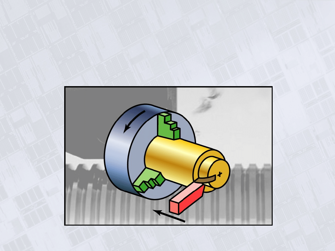
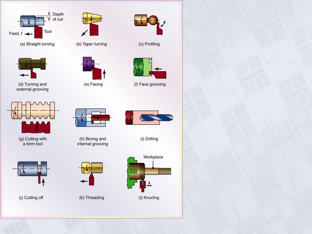
Figure 23.1 Miscellaneous
cutting operations that can be
performed on a lathe. Note
that all parts are circular – a
property known as
axisymmetry. The tools used,
their shape, and the processing
parameters are described
throughout this chapter.
Manufacturing, Engineering & Technology, Fifth Edition, by Serope Kalpakjian and Steven R. Schmid.
ISBN 0-13-148965-8. © 2006 Pearson Education, Inc., Upper Saddle River, NJ. All rights reserved.
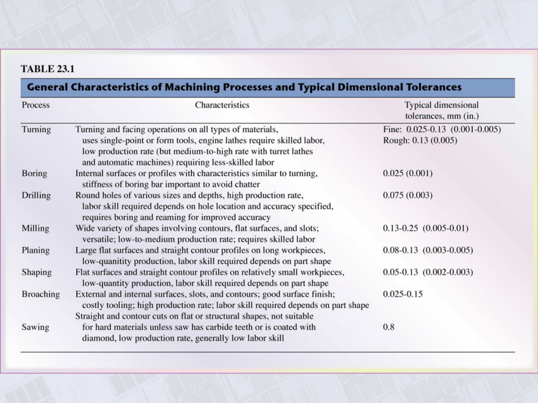
Characteristics of Machining Processes and Typical
Dimensional Tolerances
Manufacturing, Engineering & Technology, Fifth Edition, by Serope Kalpakjian and Steven R. Schmid.
ISBN 0-13-148965-8. © 2006 Pearson Education, Inc., Upper Saddle River, NJ. All rights reserved.
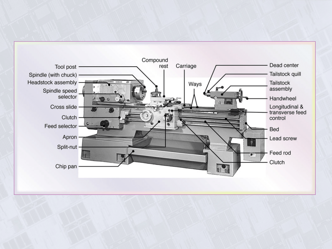
Lathe
Figure 23.2 General view of a typical lathe, showing various
components. Source: Courtesy of Heidenreich & Harbeck.
Manufacturing, Engineering & Technology, Fifth Edition, by Serope Kalpakjian and Steven R. Schmid.
ISBN 0-13-148965-8. © 2006 Pearson Education, Inc., Upper Saddle River, NJ. All rights reserved.
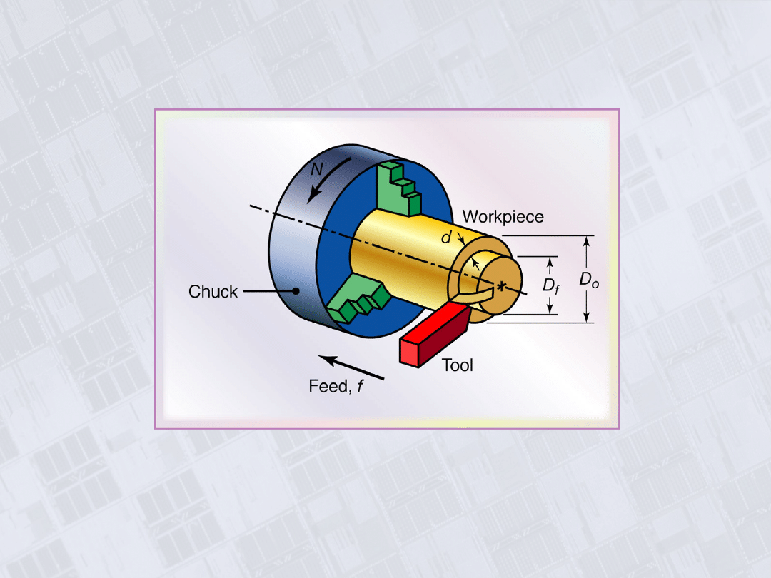
Turning Operation
Figure 23.3 Schematic illustration of the basic turning operation, showing
depth-of-cut, d; feed, f; and spindle rotational speed, N in rev/min. Cutting
speed is the surface speed of the workpiece at the tool tip.
Manufacturing, Engineering & Technology, Fifth Edition, by Serope Kalpakjian and Steven R. Schmid.
ISBN 0-13-148965-8. © 2006 Pearson Education, Inc., Upper Saddle River, NJ. All rights reserved.
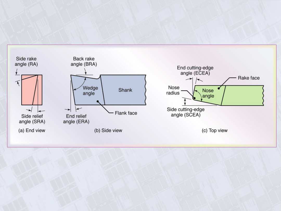
Designations for a Right-Hand Cutting Tool
Figure 23.4 Designations for a right-hand cutting tool. Right-hand means
the tool travels form right to left, as shown in Fig. 23.3.
Manufacturing, Engineering & Technology, Fifth Edition, by Serope Kalpakjian and Steven R. Schmid.
ISBN 0-13-148965-8. © 2006 Pearson Education, Inc., Upper Saddle River, NJ. All rights reserved.
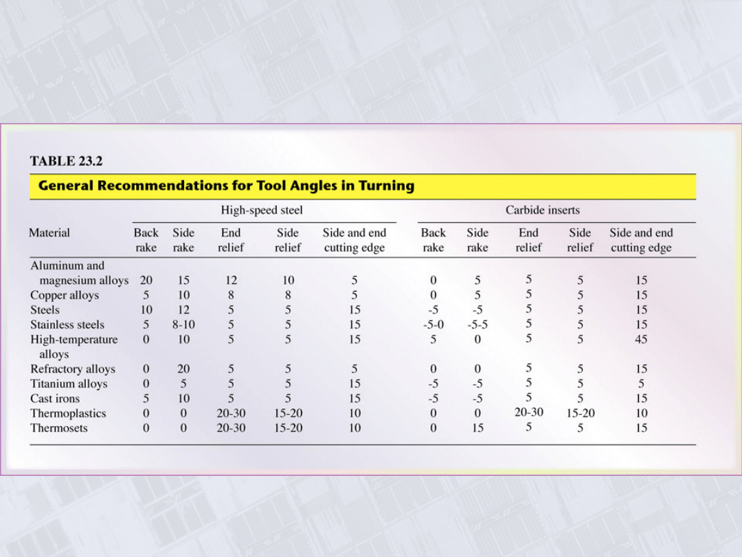
General Recommendations for Tool Angles in
Turning
Manufacturing, Engineering & Technology, Fifth Edition, by Serope Kalpakjian and Steven R. Schmid.
ISBN 0-13-148965-8. © 2006 Pearson Education, Inc., Upper Saddle River, NJ. All rights reserved.
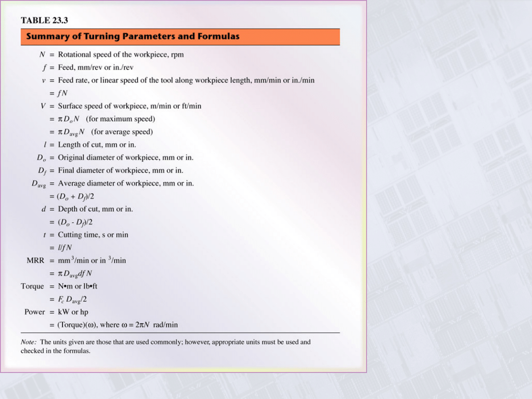
Summary of
Turning
Parameters
and
Formulas
Manufacturing, Engineering & Technology, Fifth Edition, by Serope Kalpakjian and Steven R. Schmid.
ISBN 0-13-148965-8. © 2006 Pearson Education, Inc., Upper Saddle River, NJ. All rights reserved.
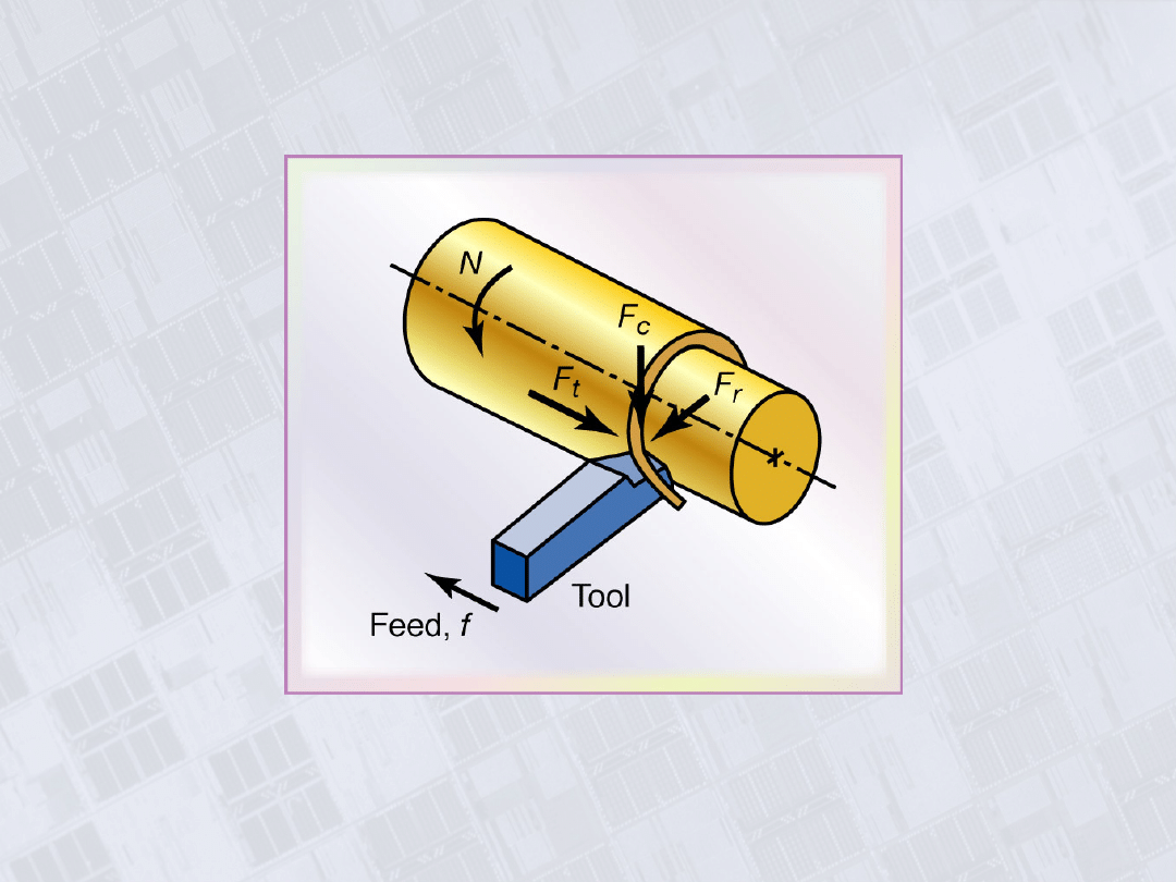
Forces Acting on a Cutting Tool in Turning
Figure 23.5 Forces acting on a cuttin tool in turning, F
c
is the
cutting force, F
t
is the thrust of feed force (in the direction of feed),
and F
r
is the radial force that tends to push the tool away from the
workpiece being machined.
Manufacturing, Engineering & Technology, Fifth Edition, by Serope Kalpakjian and Steven R. Schmid.
ISBN 0-13-148965-8. © 2006 Pearson Education, Inc., Upper Saddle River, NJ. All rights reserved.
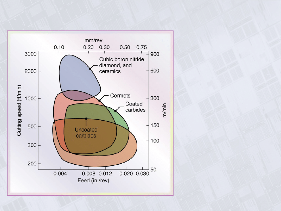
Range of Applicable Cutting Speeds and Feeds for
Tool Materials
Figure 23.6 The range of
applicable cutting speeds
and feeds for a variety of
tool materials.
Manufacturing, Engineering & Technology, Fifth Edition, by Serope Kalpakjian and Steven R. Schmid.
ISBN 0-13-148965-8. © 2006 Pearson Education, Inc., Upper Saddle River, NJ. All rights reserved.
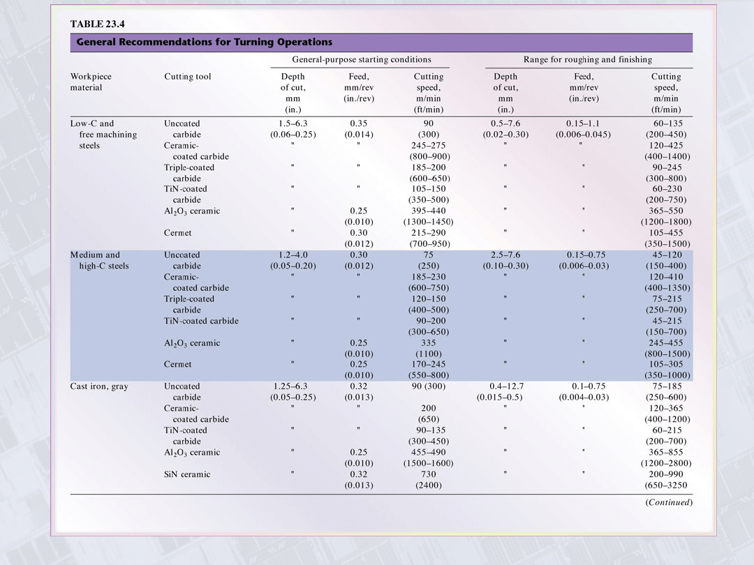
General Recommendations for Turning
Operations
Manufacturing, Engineering & Technology, Fifth Edition, by Serope Kalpakjian and Steven R. Schmid.
ISBN 0-13-148965-8. © 2006 Pearson Education, Inc., Upper Saddle River, NJ. All rights reserved.
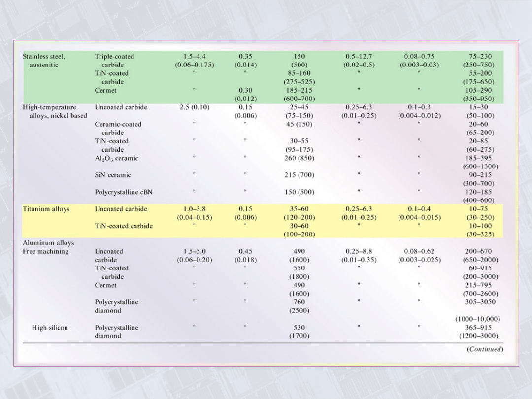
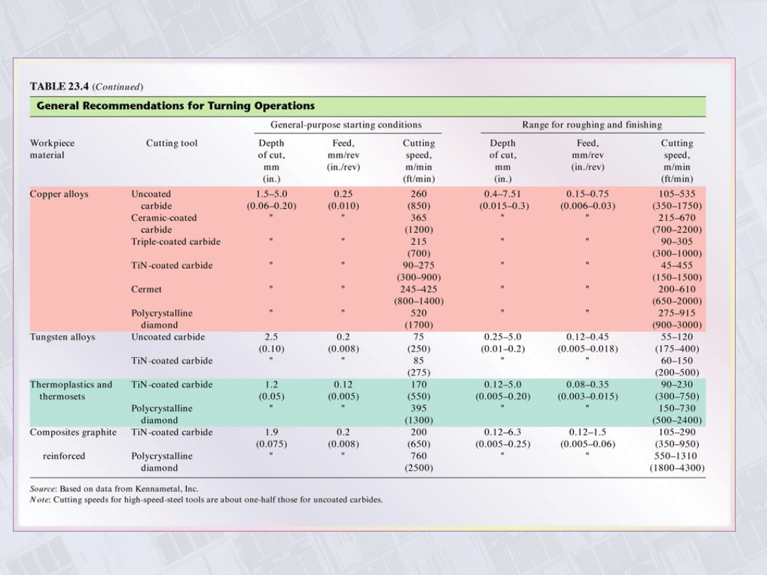
General Recommendations for Turning Operations,
con’t.
Manufacturing, Engineering & Technology, Fifth Edition, by Serope Kalpakjian and Steven R. Schmid.
ISBN 0-13-148965-8. © 2006 Pearson Education, Inc., Upper Saddle River, NJ. All rights reserved.
General Recommendations for Turning Operations,
con’t
Manufacturing, Engineering & Technology, Fifth Edition, by Serope Kalpakjian and Steven R. Schmid.
ISBN 0-13-148965-8. © 2006 Pearson Education, Inc., Upper Saddle River, NJ. All rights reserved.
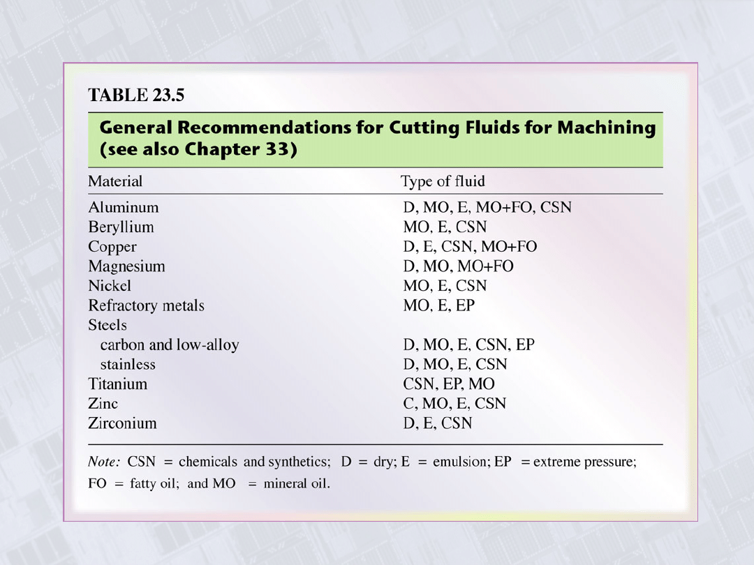
General Recommendations for Cutting Fluids for
Machining
Manufacturing, Engineering & Technology, Fifth Edition, by Serope Kalpakjian and Steven R. Schmid.
ISBN 0-13-148965-8. © 2006 Pearson Education, Inc., Upper Saddle River, NJ. All rights reserved.
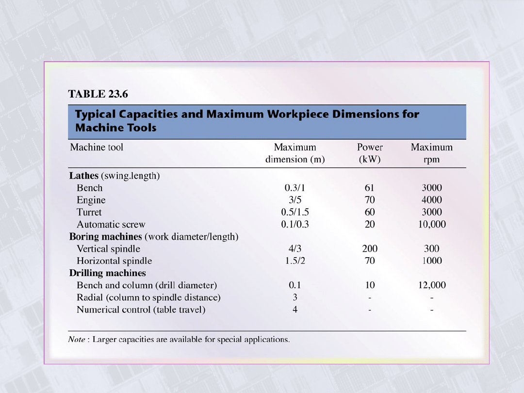
Typical Capacities and Maximum Workpiece
Dimensions for Machine Tools
Manufacturing, Engineering & Technology, Fifth Edition, by Serope Kalpakjian and Steven R. Schmid.
ISBN 0-13-148965-8. © 2006 Pearson Education, Inc., Upper Saddle River, NJ. All rights reserved.
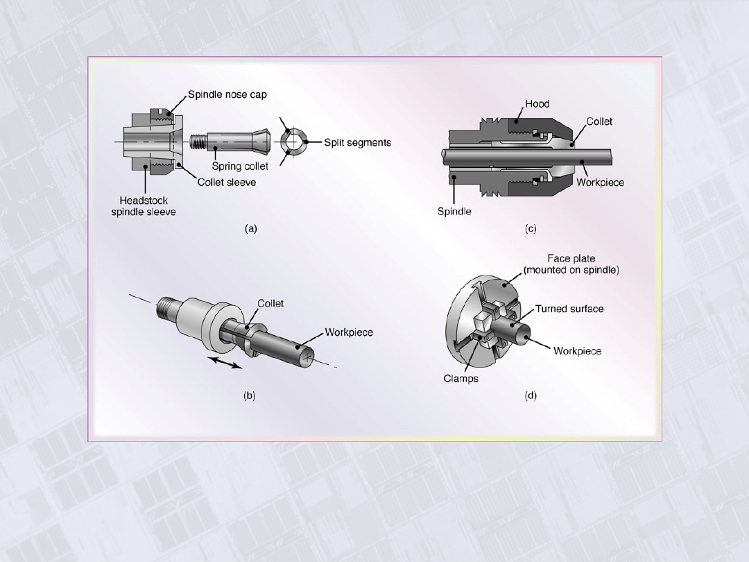
Collets
Figure 23.7 (a) and (b) Schematic illustrations of a draw-in type collet.
The workpiece is placed in the collet hole, and the conical surfaces of the
collet are forced inwards by pulling it with a draw bar into the sleeve. (c)
A push-out type collet. (d) Workholding of a workpiece on a face plate.
Manufacturing, Engineering & Technology, Fifth Edition, by Serope Kalpakjian and Steven R. Schmid.
ISBN 0-13-148965-8. © 2006 Pearson Education, Inc., Upper Saddle River, NJ. All rights reserved.
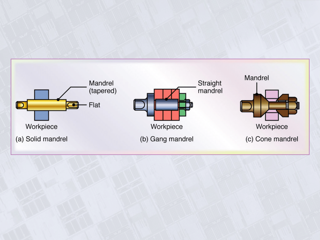
Mandrels to Hold Workpieces for Turning
Figure 23.8 Various types of mandrels to hold workpieces for turning. These
mandrels usually are mounted between centers on a lathe. Note that in (a),
both the cylindrical and the end faces of the workpiece can be machined,
whereas in (b) and (c), only the cylindrical surfaces can be machined.
Manufacturing, Engineering & Technology, Fifth Edition, by Serope Kalpakjian and Steven R. Schmid.
ISBN 0-13-148965-8. © 2006 Pearson Education, Inc., Upper Saddle River, NJ. All rights reserved.
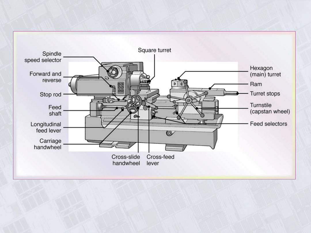
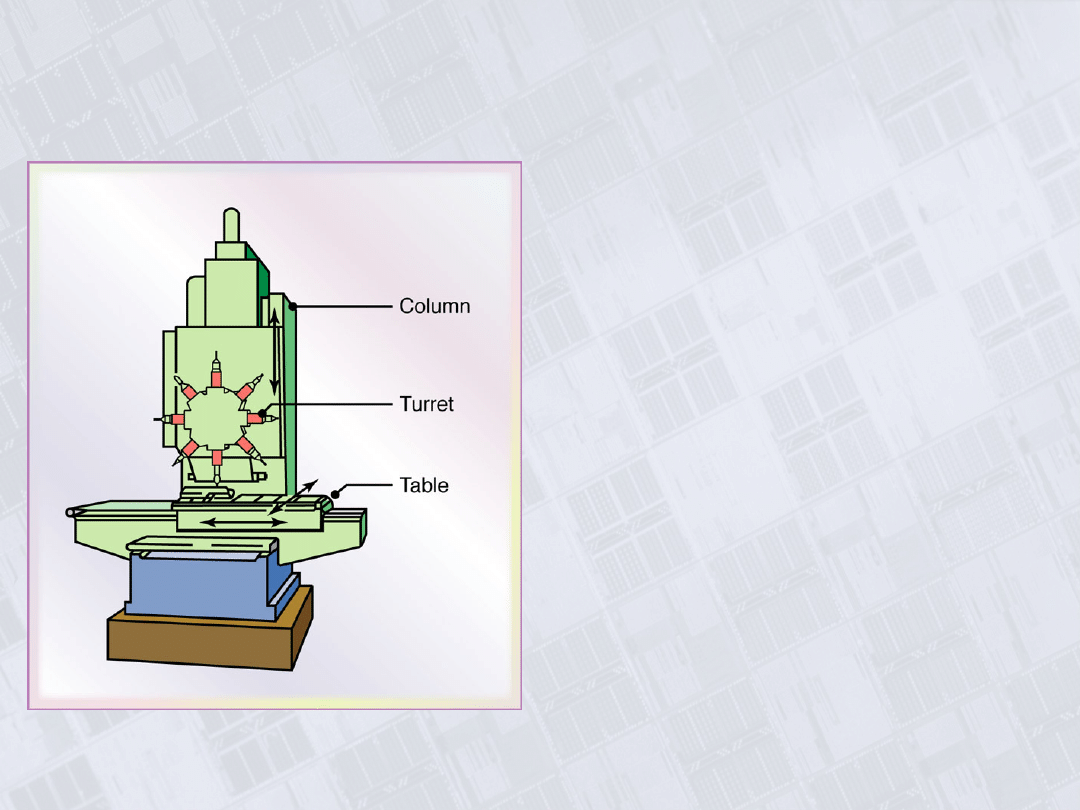
Turret Lathe
Figure 23.9 Schematic illustration of the components of a
turret lathe. Note the two turrets: square and hexagonal
(main).
Manufacturing, Engineering & Technology, Fifth Edition, by Serope Kalpakjian and Steven R. Schmid.
ISBN 0-13-148965-8. © 2006 Pearson Education, Inc., Upper Saddle River, NJ. All rights reserved.
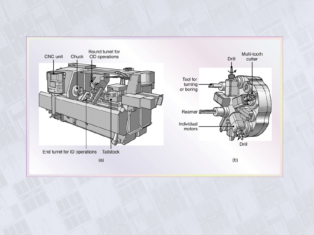
Numerical Control Lathe and Turret
Figure 23.10 (a) A computer numerical-control lathe. Note the two
turrets on this machine. These machines have higher power and
spindle speed than other lathes in order to take advantage of new
cutting tools with enhanced properties. (b) A typical turret equipped
with ten tools, some of which are powered.
Manufacturing, Engineering & Technology, Fifth Edition, by Serope Kalpakjian and Steven R. Schmid.
ISBN 0-13-148965-8. © 2006 Pearson Education, Inc., Upper Saddle River, NJ. All rights reserved.
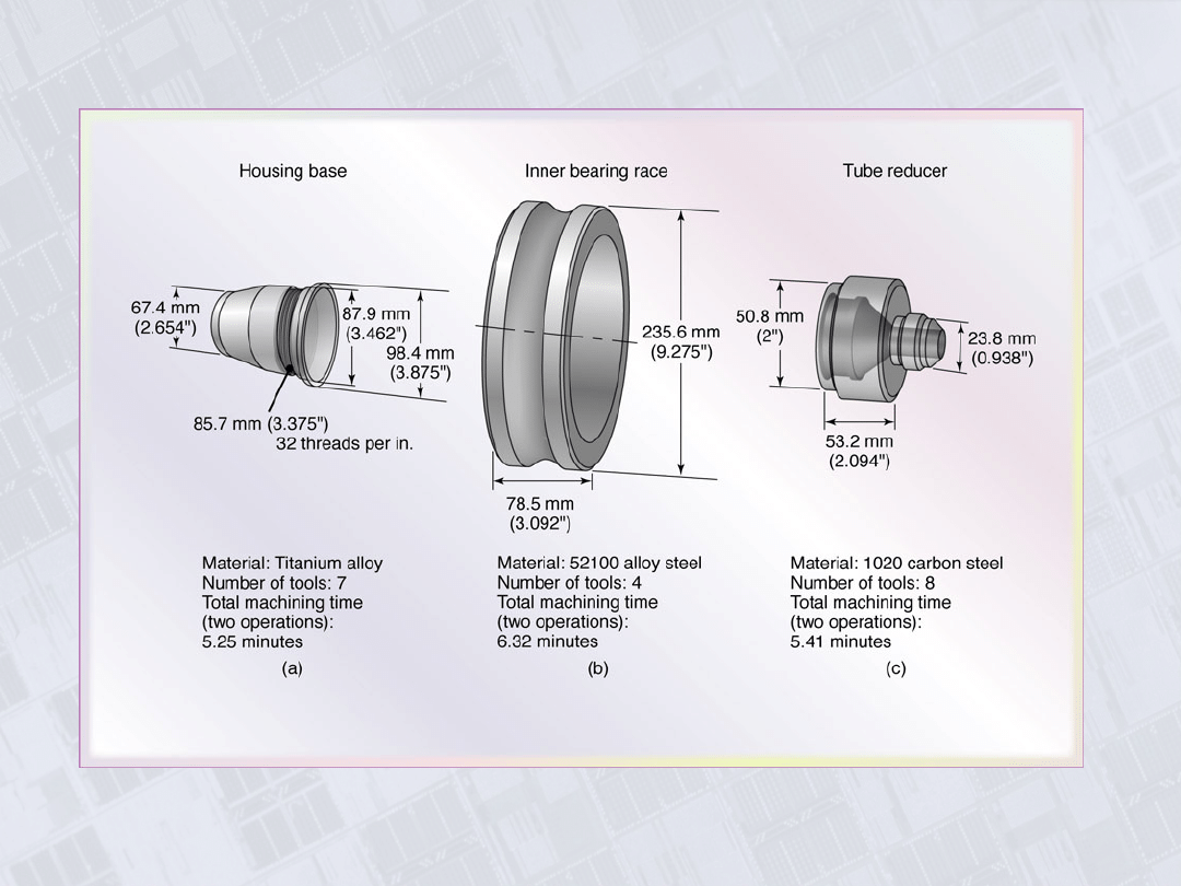
Parts Made on CNC Lathes
Figure 23.11 Typical parts made on CNC
lathes.
Manufacturing, Engineering & Technology, Fifth Edition, by Serope Kalpakjian and Steven R. Schmid.
ISBN 0-13-148965-8. © 2006 Pearson Education, Inc., Upper Saddle River, NJ. All rights reserved.
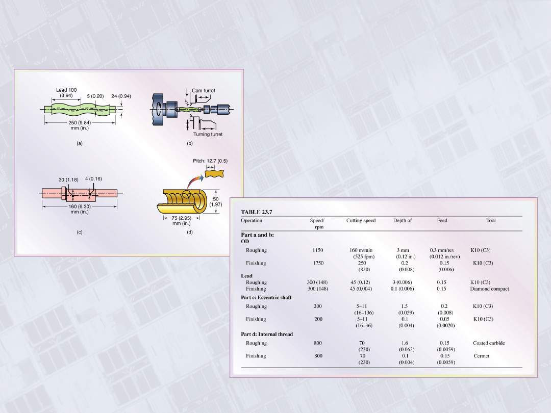
Example 23.3: Machining of Complex Shapes
Figure 23.12 Examples of more complex
shapes that can be produced on a CNC
lathe.
Manufacturing, Engineering & Technology, Fifth Edition, by Serope Kalpakjian and Steven R. Schmid.
ISBN 0-13-148965-8. © 2006 Pearson Education, Inc., Upper Saddle River, NJ. All rights reserved.
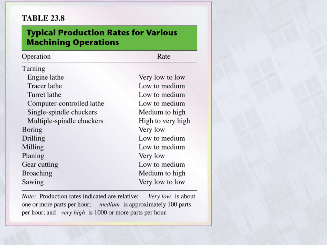
Typical
Production
Rates for
Various
Machining
Operations
Manufacturing, Engineering & Technology, Fifth Edition, by Serope Kalpakjian and Steven R. Schmid.
ISBN 0-13-148965-8. © 2006 Pearson Education, Inc., Upper Saddle River, NJ. All rights reserved.
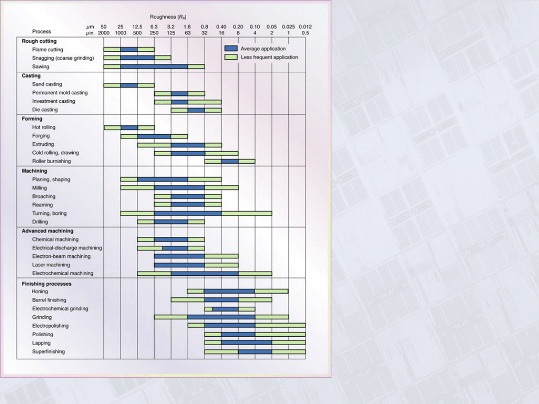
Range of Surface
Roughnesses in
Machining
Processes
Figure 23.13 The range of
surface roughnesses
obtained in various
machining processes. Note
the wide range within each
group, especially in turning
and boring.
Manufacturing, Engineering & Technology, Fifth Edition, by Serope Kalpakjian and Steven R. Schmid.
ISBN 0-13-148965-8. © 2006 Pearson Education, Inc., Upper Saddle River, NJ. All rights reserved.
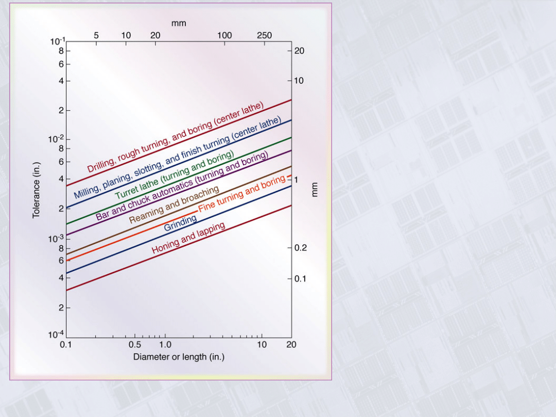
Range of
Dimensional
Tolerances in
Machining as a
Function of
Workpiece Size
Figure 23.14 Range of
dimensional tolerances
obtained in various
machining processes as a
function of workpiece size.
Note that there is an order os
magnitude difference
between small and large
workpieces.
Manufacturing, Engineering & Technology, Fifth Edition, by Serope Kalpakjian and Steven R. Schmid.
ISBN 0-13-148965-8. © 2006 Pearson Education, Inc., Upper Saddle River, NJ. All rights reserved.
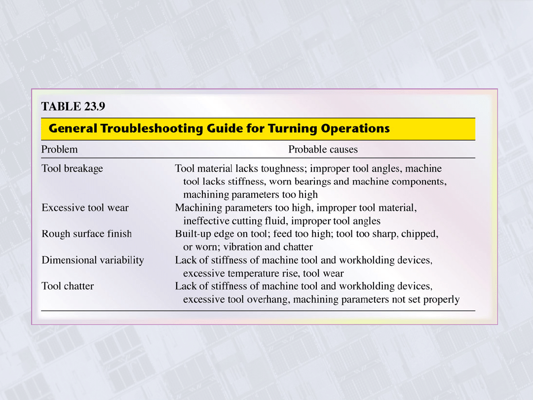
Troubleshooting Guide for Turning
Manufacturing, Engineering & Technology, Fifth Edition, by Serope Kalpakjian and Steven R. Schmid.
ISBN 0-13-148965-8. © 2006 Pearson Education, Inc., Upper Saddle River, NJ. All rights reserved.
Cutting
Screw
Threads
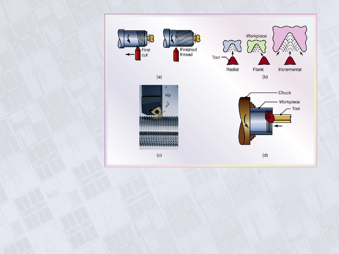
Figure 23.15 (a) Cutting screw threads on a lathe with a single-point cutting tool. (b)
Cutting screw threads with a single-point tool in several passes, normally utilized for large
threads. The small arrows in the figures show the direction of the feed, and the broken lines
show the position of the cutting tool as time progresses. Note that in radial cutting, the tool
is fed directly into the workpiece. In flank cutting, the tool is fed inot the piece along the
right face of the thread. In incremental cutting, the tool is first fed directly into the piece at
the center of the thread, then at its sides, and finally into the root. (c) A typical coated-
carbide insert in the process of cutting screw threads on a round shaft. (d) Cutting internal
screw threads with a carbide insert. Source: (c): Courtesy of Iscar Metals Inc.
Manufacturing, Engineering & Technology, Fifth Edition, by Serope Kalpakjian and Steven R. Schmid.
ISBN 0-13-148965-8. © 2006 Pearson Education, Inc., Upper Saddle River, NJ. All rights reserved.
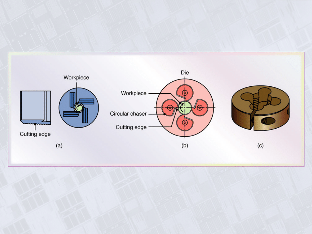
Chasers and Die for Thread Cutting
Figure 23.16 (a) Straight chasers for cutting threads
on a lathe. (b) Circular chasers. (c) A solid
threading die.
Manufacturing, Engineering & Technology, Fifth Edition, by Serope Kalpakjian and Steven R. Schmid.
ISBN 0-13-148965-8. © 2006 Pearson Education, Inc., Upper Saddle River, NJ. All rights reserved.
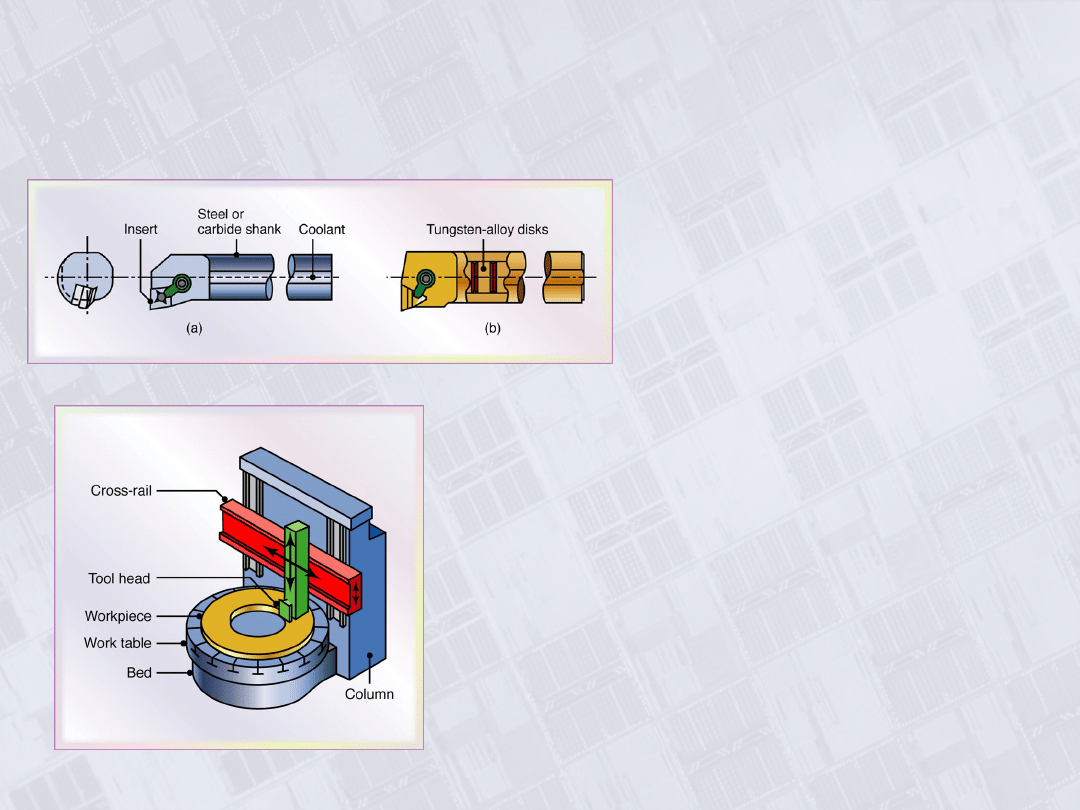
Boring and Boring Mill
Figure 23.17 (a) Schematic
illustration of a steel boring
bar with a carbide insert.
Note the passageway in the
bar for cutting fluid
application. (b) Schematic
illustration of a boring bar
with tungsten-alloy “inertia
disks” sealed in the bar to
counteract vibration and
chatter during boring. This
system is effective for boring
bar length-to-diameter ratios
of up to 6.
Figure 23.18 Schematic illustration of a
vertical boring mill. Such a machine can
accommodate workpiece sizes as large as
2.5m (98 in.) in diameter.
Manufacturing, Engineering & Technology, Fifth Edition, by Serope Kalpakjian and Steven R. Schmid.
ISBN 0-13-148965-8. © 2006 Pearson Education, Inc., Upper Saddle River, NJ. All rights reserved.
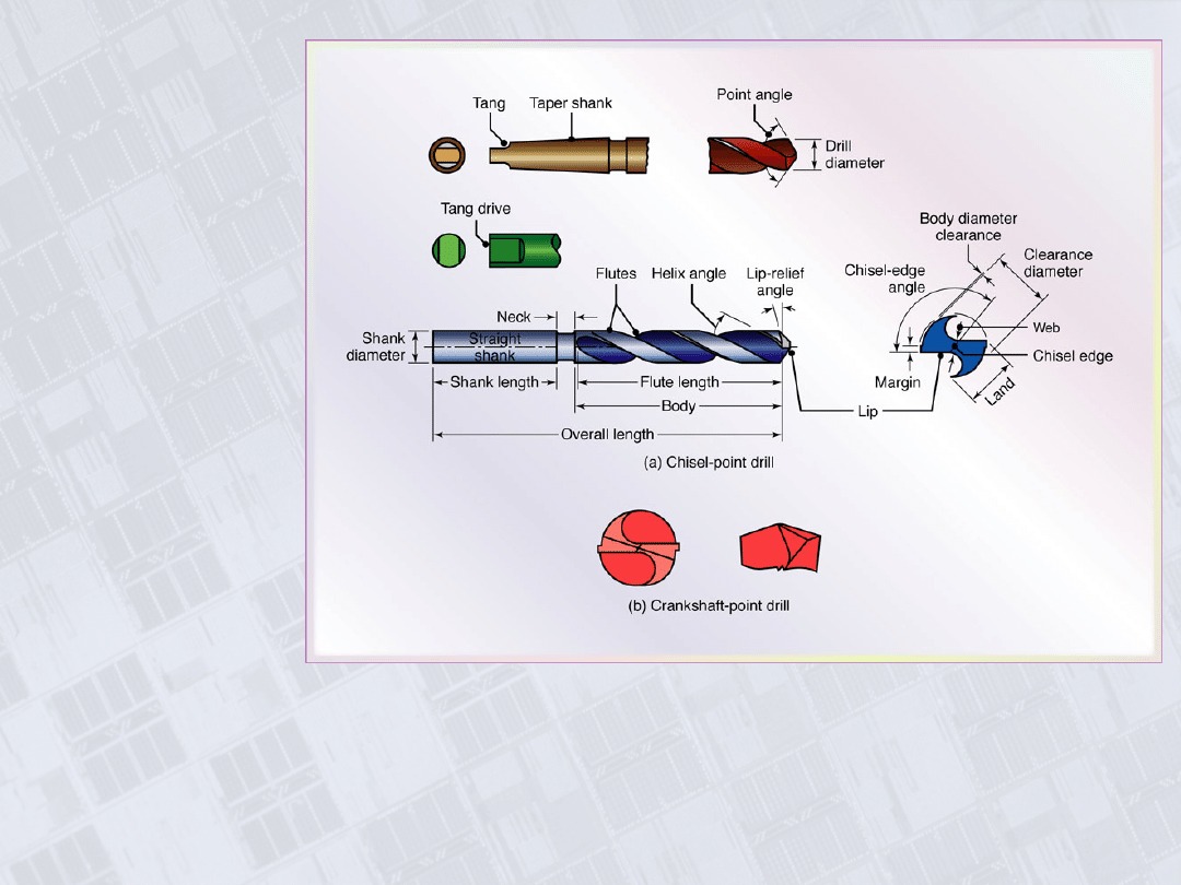
Chisel-Point
Drill and
Crankshaft
Drill
Figure 23.19 Two common types of drills: (a) Chisel-point drill. The function of the pair of
margins is to provide a bearing surface for the drill against walls of the hole as it
penetrates into the workpiece. Drills with four margins (double-margin) are available for
improved drill guidance and accuracy. Drills with chip-breaker features also are available.
(b) Crankshaft drills. These drills have good centering ability, and because chips tend to
break up easily, these drills are suitable for producing deep holes.
Manufacturing, Engineering & Technology, Fifth Edition, by Serope Kalpakjian and Steven R. Schmid.
ISBN 0-13-148965-8. © 2006 Pearson Education, Inc., Upper Saddle River, NJ. All rights reserved.
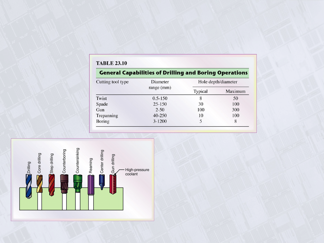
General Capabilities of Drilling
Figure 23.20 Various types of
drills and drilling and reaming
operations.
Manufacturing, Engineering & Technology, Fifth Edition, by Serope Kalpakjian and Steven R. Schmid.
ISBN 0-13-148965-8. © 2006 Pearson Education, Inc., Upper Saddle River, NJ. All rights reserved.
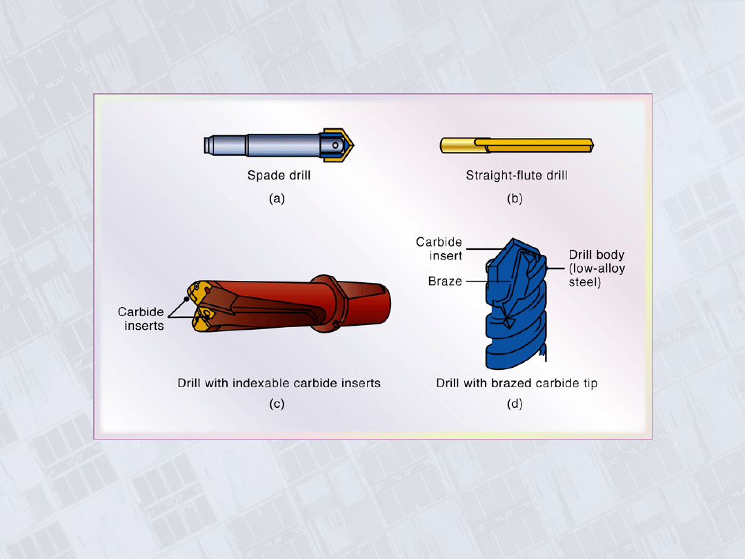
Types of Drills
Figure 23.21 Various types of
drills.
Manufacturing, Engineering & Technology, Fifth Edition, by Serope Kalpakjian and Steven R. Schmid.
ISBN 0-13-148965-8. © 2006 Pearson Education, Inc., Upper Saddle River, NJ. All rights reserved.
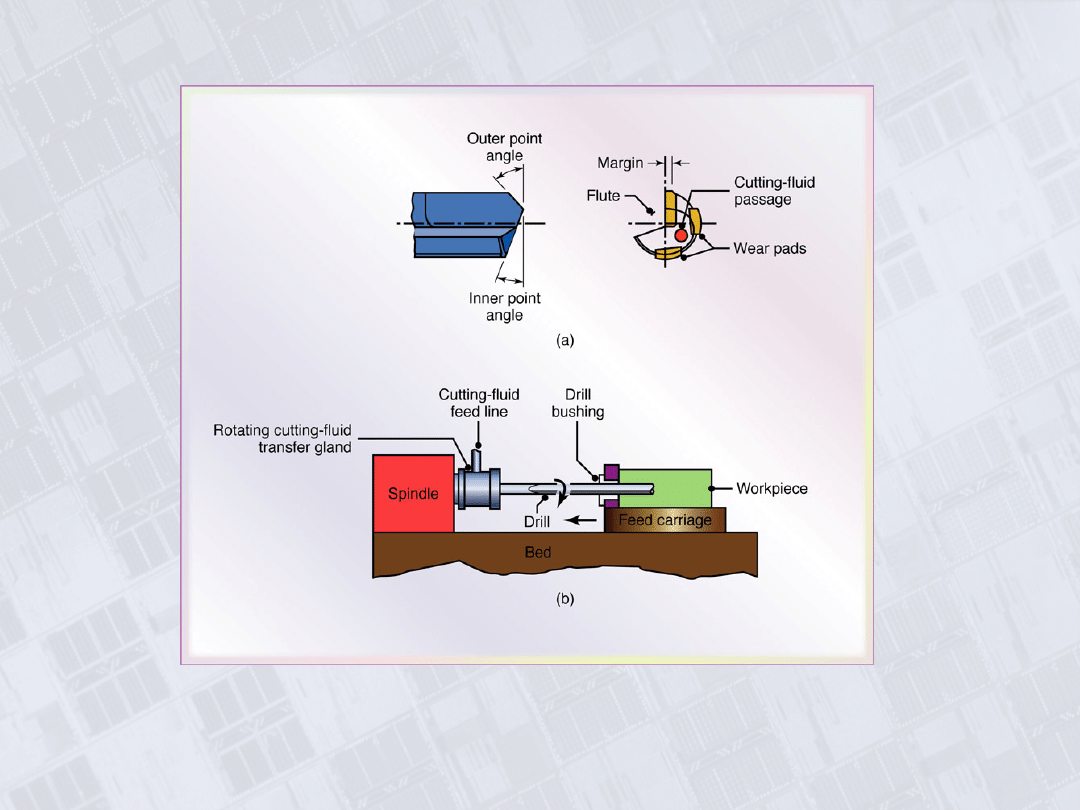
Gun Drill
Figure 23.22 (a) A gun drill showing various
features. (b) Schematic illustration of the gun-
drilling operation.
Manufacturing, Engineering & Technology, Fifth Edition, by Serope Kalpakjian and Steven R. Schmid.
ISBN 0-13-148965-8. © 2006 Pearson Education, Inc., Upper Saddle River, NJ. All rights reserved.
Trepanning
Figure 23.23 (a) Trepanning tool. (b) Trepanning with a drill-mounted
single cutter.
Manufacturing, Engineering & Technology, Fifth Edition, by Serope Kalpakjian and Steven R. Schmid.
ISBN 0-13-148965-8. © 2006 Pearson Education, Inc., Upper Saddle River, NJ. All rights reserved.
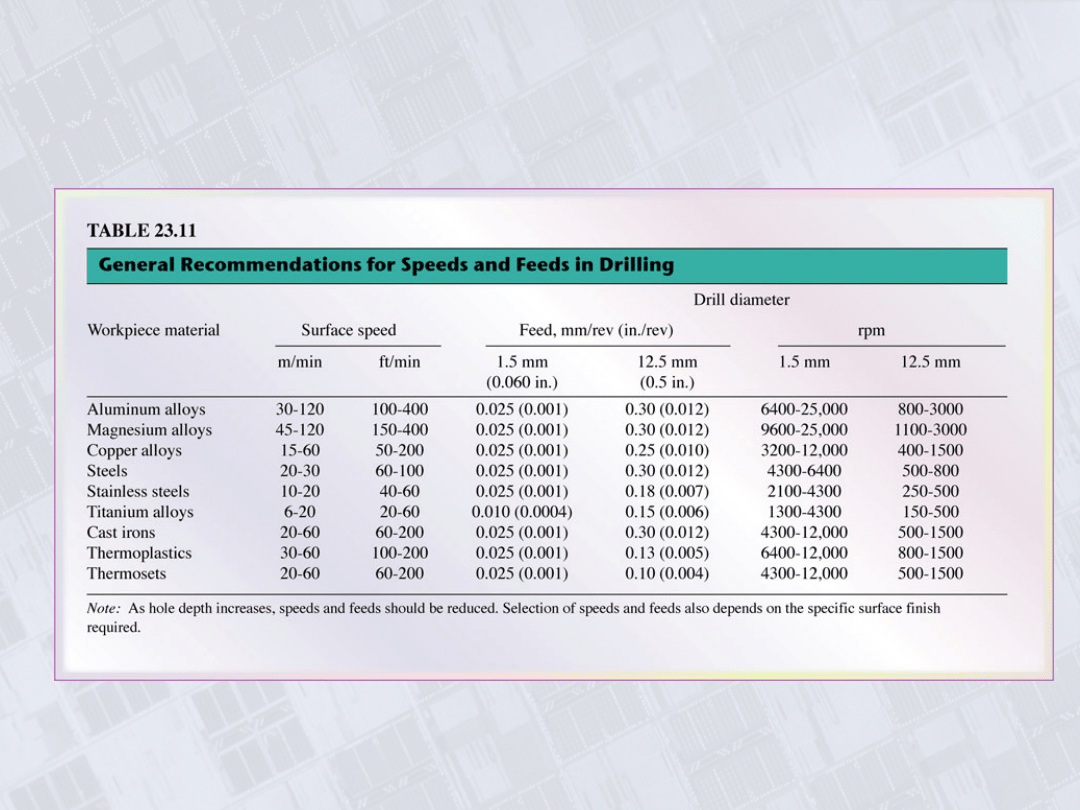
General Recommendations for Speeds and
Feeds in Drilling
Manufacturing, Engineering & Technology, Fifth Edition, by Serope Kalpakjian and Steven R. Schmid.
ISBN 0-13-148965-8. © 2006 Pearson Education, Inc., Upper Saddle River, NJ. All rights reserved.
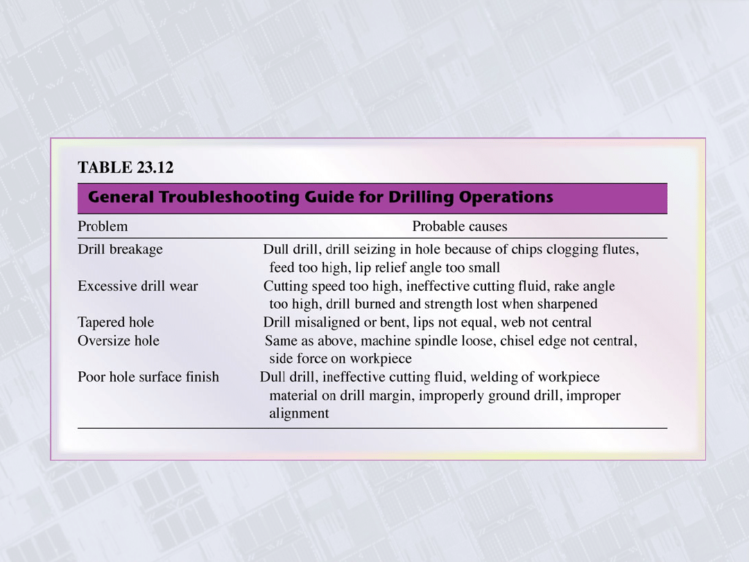
Troubleshooting Guide for Drilling
Manufacturing, Engineering & Technology, Fifth Edition, by Serope Kalpakjian and Steven R. Schmid.
ISBN 0-13-148965-8. © 2006 Pearson Education, Inc., Upper Saddle River, NJ. All rights reserved.
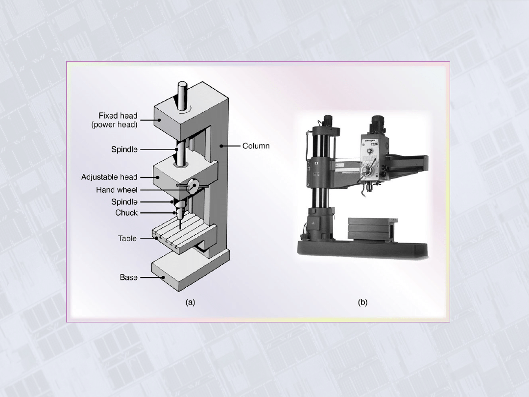
Vertical Drill Press and Radial Drilling
Machine
Figure 23.24 (a) Schematic illustration of the components of a vertical
drill press. (b) A radial drilling machine. Source: (b) Courtesy of Willis
Machinery and Tools.
Manufacturing, Engineering & Technology, Fifth Edition, by Serope Kalpakjian and Steven R. Schmid.
ISBN 0-13-148965-8. © 2006 Pearson Education, Inc., Upper Saddle River, NJ. All rights reserved.
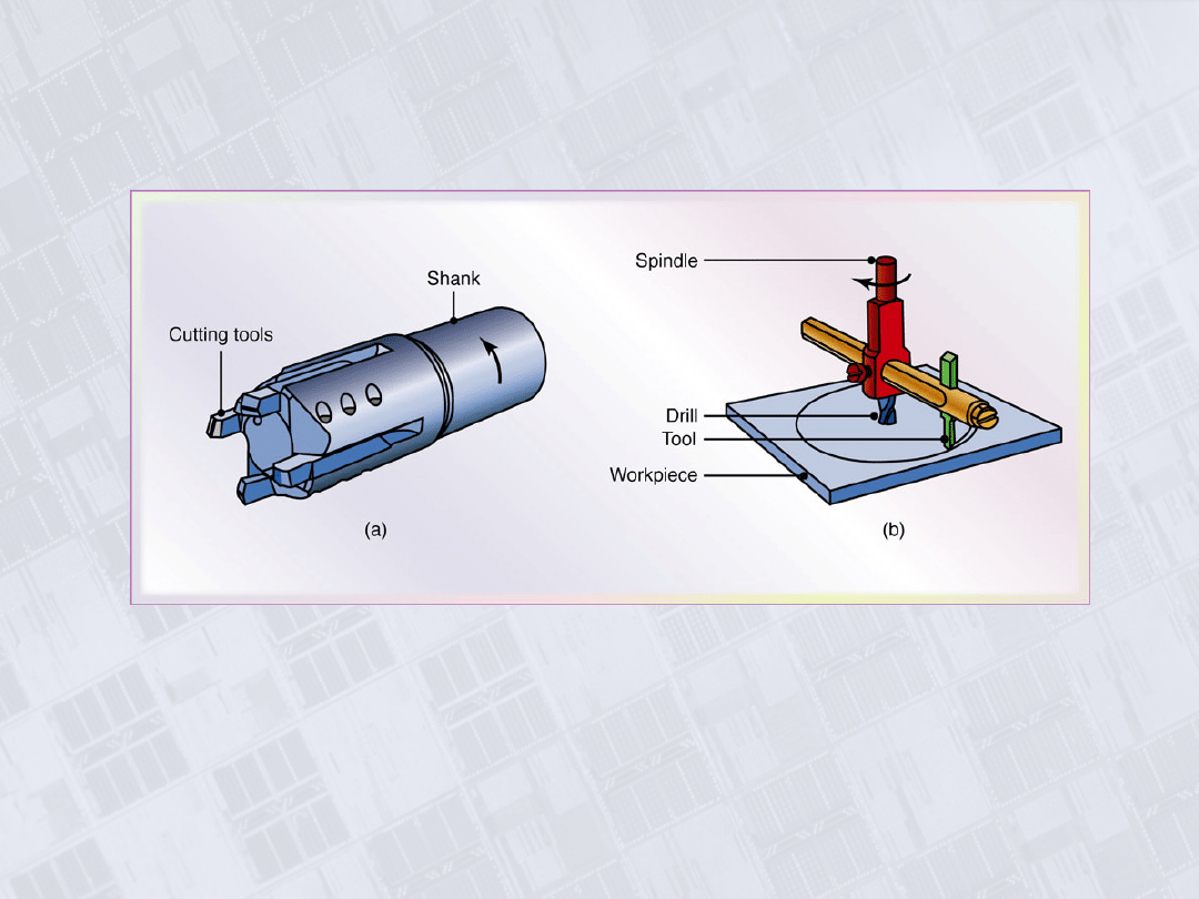
Three-Axis Computer Numerical-Control
Drilling Machine
Figure 23.25 A three-axis computer
numerical-control drilling machine.
The turret holds as many as eight
different tools, such as drills, taps,
and reamers.
Manufacturing, Engineering & Technology, Fifth Edition, by Serope Kalpakjian and Steven R. Schmid.
ISBN 0-13-148965-8. © 2006 Pearson Education, Inc., Upper Saddle River, NJ. All rights reserved.
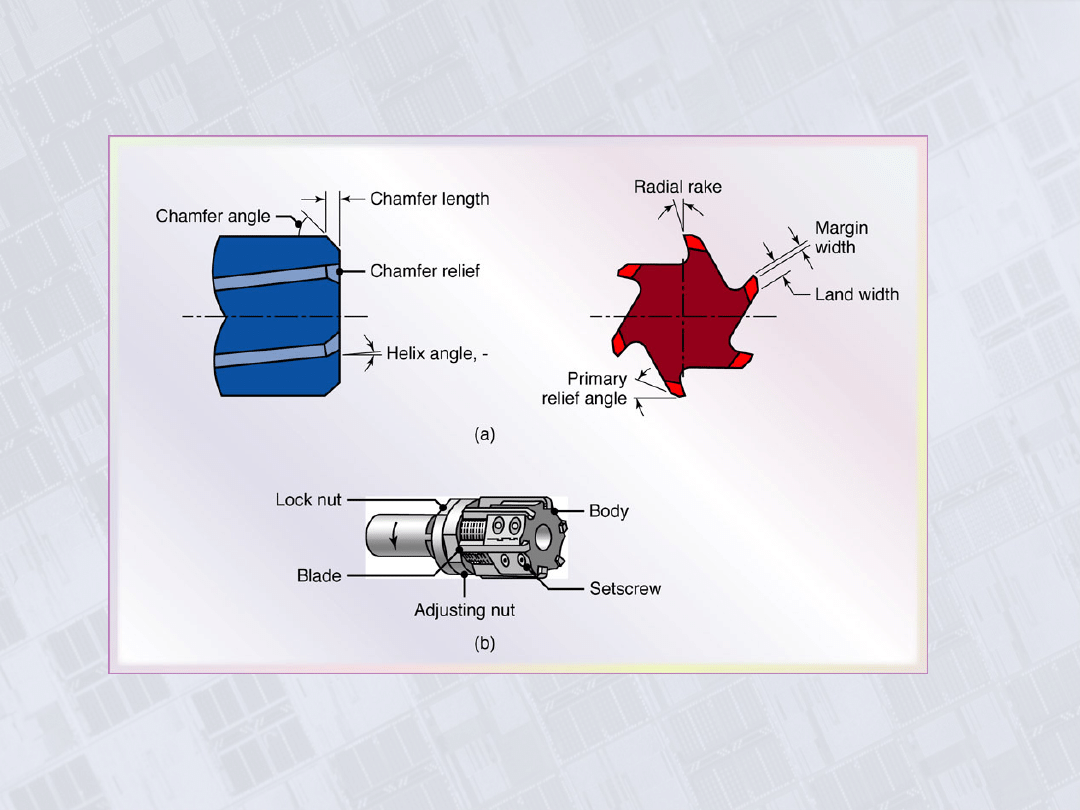
Helical Reamer and Inserted-Blade Adjustable
Reamer
Figure 23.26 (a) Terminology for a helical
reamer. (b) Inserted-blade adjustable reamer.
Manufacturing, Engineering & Technology, Fifth Edition, by Serope Kalpakjian and Steven R. Schmid.
ISBN 0-13-148965-8. © 2006 Pearson Education, Inc., Upper Saddle River, NJ. All rights reserved.
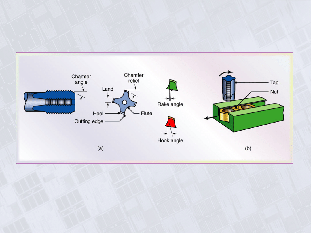
Tapping
Figure 23.27 (a) Terminology for a tap. (b) Tapping of steel nuts in
production.
Manufacturing, Engineering & Technology, Fifth Edition, by Serope Kalpakjian and Steven R. Schmid.
ISBN 0-13-148965-8. © 2006 Pearson Education, Inc., Upper Saddle River, NJ. All rights reserved.
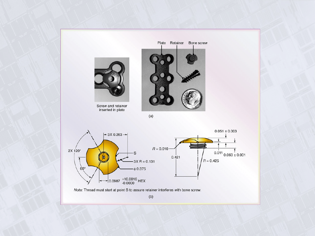
Cervical Spine Implant
Figure 23.28 A cervical spine implant.
Document Outline
- Chapter 23
- Lathe Cutting Operations
- Characteristics of Machining Processes and Typical Dimensional Tolerances
- Lathe
- Turning Operation
- Designations for a Right-Hand Cutting Tool
- General Recommendations for Tool Angles in Turning
- Summary of Turning Parameters and Formulas
- Forces Acting on a Cutting Tool in Turning
- Range of Applicable Cutting Speeds and Feeds for Tool Materials
- General Recommendations for Turning Operations
- General Recommendations for Turning Operations, con’t.
- General Recommendations for Turning Operations, con’t
- General Recommendations for Cutting Fluids for Machining
- Typical Capacities and Maximum Workpiece Dimensions for Machine Tools
- Collets
- Mandrels to Hold Workpieces for Turning
- Turret Lathe
- Numerical Control Lathe and Turret
- Parts Made on CNC Lathes
- Example 23.3: Machining of Complex Shapes
- Typical Production Rates for Various Machining Operations
- Range of Surface Roughnesses in Machining Processes
- Range of Dimensional Tolerances in Machining as a Function of Workpiece Size
- Troubleshooting Guide for Turning
- Cutting Screw Threads
- Chasers and Die for Thread Cutting
- Boring and Boring Mill
- Chisel-Point Drill and Crankshaft Drill
- General Capabilities of Drilling
- Types of Drills
- Gun Drill
- Trepanning
- General Recommendations for Speeds and Feeds in Drilling
- Troubleshooting Guide for Drilling
- Vertical Drill Press and Radial Drilling Machine
- Three-Axis Computer Numerical-Control Drilling Machine
- Helical Reamer and Inserted-Blade Adjustable Reamer
- Tapping
- Cervical Spine Implant
Wyszukiwarka
Podobne podstrony:
10 Easy Steps to Turning Dreams into Reality!
BW ch23
Ch23 pg753 774
Capability of high pressure cooling in the turning of surface hardened piston rods
Ch23 Shafts
ch23
Lathe Turning Tips
ch23
Kuzmin, Alexey Sicilian Rauzer Turning a New Page
Ball Turning Toolpost Complete
Cassels Selling Sickness How Drug Companies are Turning Us All into Patients
CH23
10 Easy Steps to Turning Dreams into Reality!
BW ch23
Erle Stanley Gardner The Case of the Turning Tide (rtf)
Turning Points
Jennifer Armintrout Blood Ties 1 Blood Ties The Turning
więcej podobnych podstron