
The sound field
and how it is measured
Jakob Christensen-Dalsgaard,
Jakob Christensen-Dalsgaard,
CSC
CSC

Contents:
1.
1.
Introduction and definition of the sound
Introduction and definition of the sound
field
field
2.
2.
Parameters of sound
Parameters of sound
3.
3.
Sound emitters – acoustic monopoles and
Sound emitters – acoustic monopoles and
dipoles
dipoles
4.
4.
Manipulations of the sound field
Manipulations of the sound field
5.
5.
Measuring the sound field
Measuring the sound field
a) by the animals
a) by the animals
b) by microphones
b) by microphones

The sound field –
introduction 1
Strict definition : the sound field is
Strict definition : the sound field is
the
the
pressure gradient
pressure gradient
, i.e. the
, i.e. the
particle acceleration radiating
particle acceleration radiating
from the sound source.
from the sound source.
- an analogue to the electrical field
- an analogue to the electrical field
(the potential gradient or force
(the potential gradient or force
acting on a unit charge)
acting on a unit charge)

’Colloquial’ uses of the term
’sound field’:
Near field (1)
Near field (1)
, the region near the sound
, the region near the sound
emitter where medium motion is
emitter where medium motion is
dominated by local hydrodynamic flow –
dominated by local hydrodynamic flow –
also called the
also called the
hydrodynamic near field
hydrodynamic near field
Near field (2)
Near field (2)
, the region near the sound
, the region near the sound
emitter where sound radiation is complex
emitter where sound radiation is complex
due to interferences between sound
due to interferences between sound
radiated from different regions – also
radiated from different regions – also
called the
called the
geometric near field
geometric near field
Far field
Far field
, the region far from the sound
, the region far from the sound
emitter where medium motion is
emitter where medium motion is
dominated by the propagating sound wave
dominated by the propagating sound wave

Colloquial uses of ’sound
field’ 2
Free sound field
Free sound field
, i.e. a sound field without
, i.e. a sound field without
reflected components far away from emitter
reflected components far away from emitter
Diffuse sound field,
Diffuse sound field,
a sound field with
a sound field with
reflected component and ultimately zero
reflected component and ultimately zero
radiated sound energy
radiated sound energy
The term
The term
’closed-field sound’
’closed-field sound’
is used for
is used for
sound in small enclosures (earphone
sound in small enclosures (earphone
couplers) that are essentially pressure
couplers) that are essentially pressure
chambers.
chambers.
Pressure and motion
parameters of sound
The sound wave propagates in an elastic
The sound wave propagates in an elastic
medium and generates alternating
medium and generates alternating
condensations and rarefactions of the
condensations and rarefactions of the
medium particles
medium particles
The particles are displaced and oscillate
The particles are displaced and oscillate
in
in
the propagation direction
the propagation direction
around their
around their
rest position (no net movements although
rest position (no net movements although
the sound wave propagates)
the sound wave propagates)
(an acoustic particle is a ’tiny bulk’ of medium,
(an acoustic particle is a ’tiny bulk’ of medium,
so small that it can be regarded as a unit and
so small that it can be regarded as a unit and
so big that it retains fluid properties)
so big that it retains fluid properties)
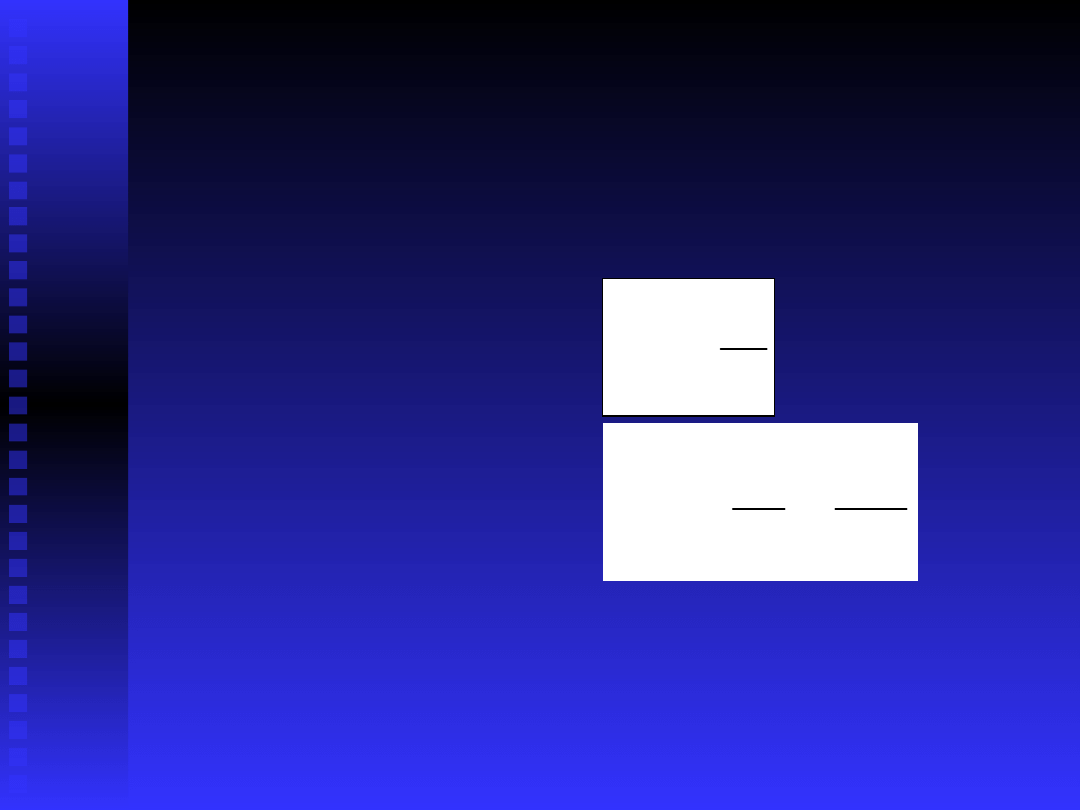
Motion parameters of sound
Three related parameters are used:
Three related parameters are used:
1.
1.
Displacement
Displacement
, x(t)
, x(t)
2.
2.
Velocity
Velocity
3.
3.
Acceleration
Acceleration
NB. Particle velocity should not be confused with
NB. Particle velocity should not be confused with
sound velocity. Particle velocity is proportional
sound velocity. Particle velocity is proportional
to source level, whereas sound velocity is a
to source level, whereas sound velocity is a
constant only depending on properties of the
constant only depending on properties of the
medium.
medium.
t
x
t
v
)
(
2
2
)
(
t
x
t
v
t
a

Motion parameters of
sound 2
The medium motion parameters are
The medium motion parameters are
vectors
vectors
parallel to the propagation direction of the
parallel to the propagation direction of the
sound wave and thus
sound wave and thus
directional
directional
Sound pressure
Sound pressure
, in contrast, is non-
, in contrast, is non-
directional
directional
However, the
However, the
pressure gradient
pressure gradient
is directional
is directional
Note that the motion parameters are
Note that the motion parameters are
ambiguous
ambiguous
- the particles oscillate both
- the particles oscillate both
parallel
parallel
and
and
antiparallel
antiparallel
to the sound
to the sound
propagation direction.
propagation direction.
1
2
3
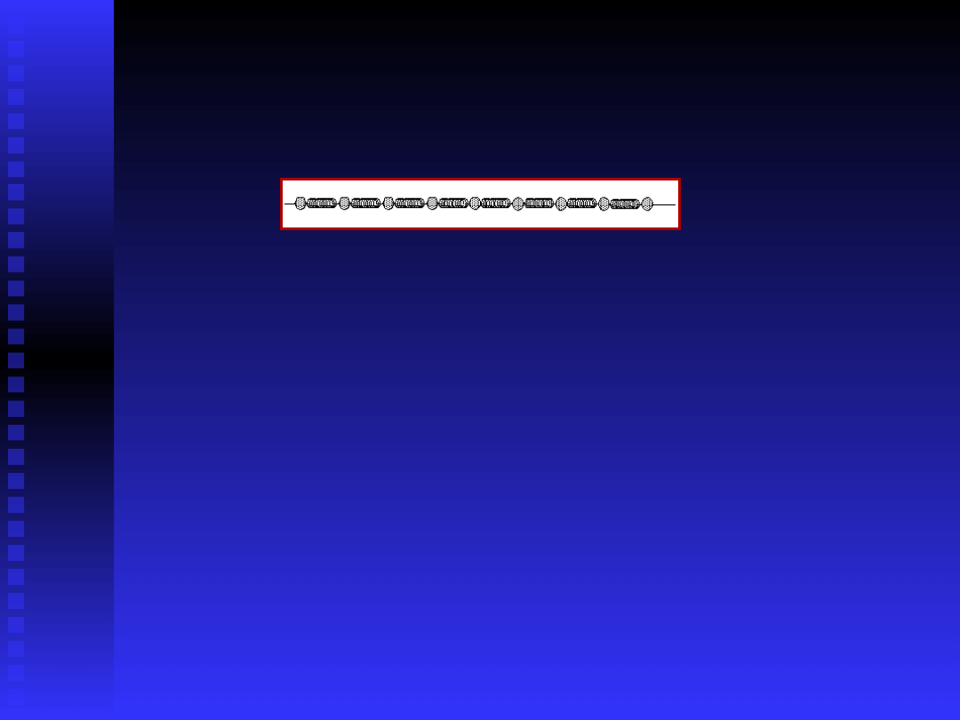
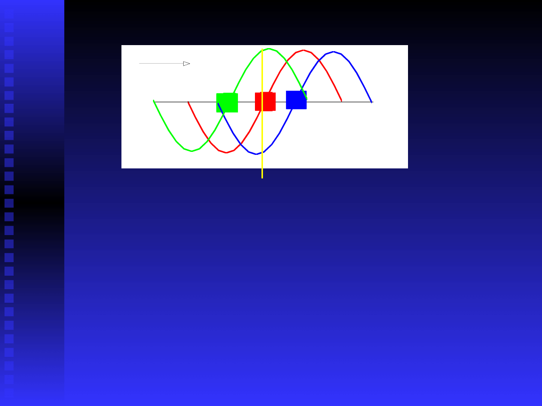
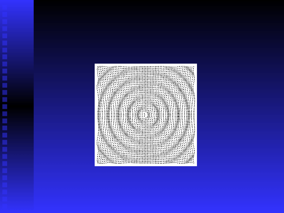
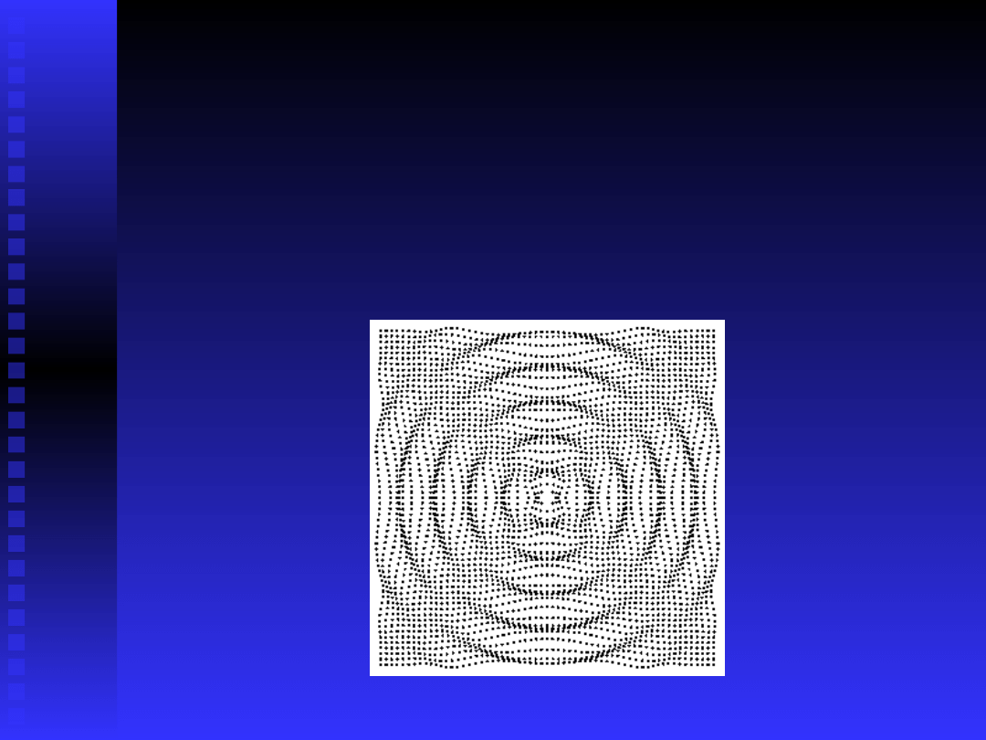
Propagation of the sound
wave.
The figure shows the time course of displacement experienced
The figure shows the time course of displacement experienced
by each of the acoustic particles as the sound propagates
by each of the acoustic particles as the sound propagates
(direction shown by left arrow) (note that the particles are
(direction shown by left arrow) (note that the particles are
displaced along the axis (black line) only).
displaced along the axis (black line) only).
Particle 1 leads and at the instant when particle 2 has its peak
Particle 1 leads and at the instant when particle 2 has its peak
velocity - at rest position – particle 1 and 3 move against it,
velocity - at rest position – particle 1 and 3 move against it,
creating a peak pressure.
creating a peak pressure.
Therefore, the particle velocity is
Therefore, the particle velocity is
in phase with the pressure in the propagating sound wave.
in phase with the pressure in the propagating sound wave.
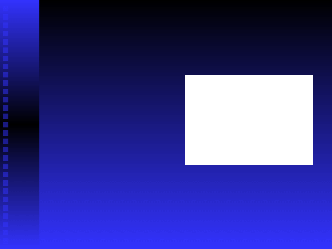
Particle velocity
Close to the sound source there is no simple relation
Close to the sound source there is no simple relation
between pressure and particle velocity. Velocity must be
between pressure and particle velocity. Velocity must be
measured independently
measured independently
From Newtons 2. Law,
From Newtons 2. Law,
Thus, velocity is proportional to the integral of the
Thus, velocity is proportional to the integral of the
pressure gradient
pressure gradient
Note that particle velocities are much smaller in water
Note that particle velocities are much smaller in water
than in air (by a factor 3570 for identical sound pressures)
than in air (by a factor 3570 for identical sound pressures)
dt
r
p
v
r
p
t
v
r
r
1

Particle velocity 2
Particle velocity can be measured by estimating the
Particle velocity can be measured by estimating the
pressure gradient.
pressure gradient.
This is done by measuring the pressure difference
This is done by measuring the pressure difference
on two closely spaced hydrophones or
on two closely spaced hydrophones or
microphones, integrating and scaling,
microphones, integrating and scaling,
i.e.
i.e.
Note that this is the velocity component on the axis
Note that this is the velocity component on the axis
of the two transducers. There are two additional
of the two transducers. There are two additional
orthogonal components of particle velocity.
orthogonal components of particle velocity.
dt
r
t
p
t
p
t
v
r
)
(
)
(
1
)
(
2
1
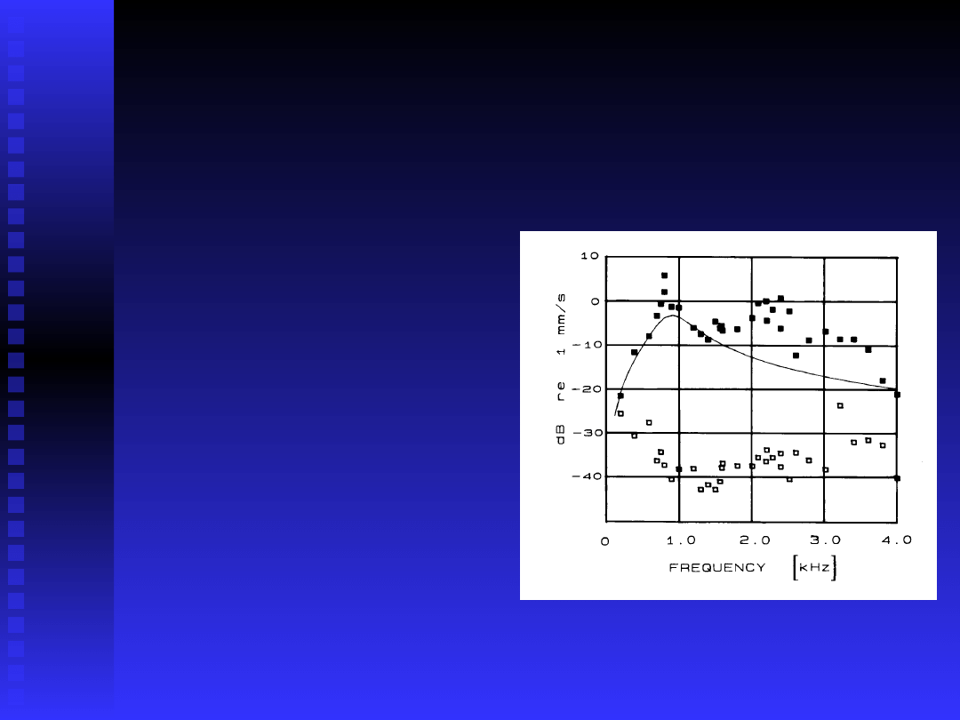
Particle velocity
measurements-
an example
The figure shows laser
The figure shows laser
measurements of
measurements of
clawed frog tympanic
clawed frog tympanic
disk vibrations (filled
disk vibrations (filled
squares) and particle
squares) and particle
velocities measured
velocities measured
using the pressure
using the pressure
gradient method (two
gradient method (two
closely spaced
closely spaced
hydrophones)
hydrophones)
(from Christensen-
(from Christensen-
Dalsgaard et al. 1990)
Dalsgaard et al. 1990)

Sound intensity 1
Far away from the sound source
Far away from the sound source
(local flow is negligible) sound
(local flow is negligible) sound
pressure and particle velocity are
pressure and particle velocity are
related by Ohms acoustical law
related by Ohms acoustical law
where Z is the characteristic
where Z is the characteristic
impedance of the medium,
impedance of the medium,
the
the
density and c the speed of sound
density and c the speed of sound
Here sound intensity (energy flow
Here sound intensity (energy flow
per unit area) can be calculated as:
per unit area) can be calculated as:
c
Z
Z
v
p
,
c
p
v
p
I
2
Sound intensity 2
Sound intensity is calculated from the particle
Sound intensity is calculated from the particle
velocity as the time average of pressure and
velocity as the time average of pressure and
particle velocity:
particle velocity:
Note that velocity components 90 deg out of
Note that velocity components 90 deg out of
phase with pressure cancel. These components
phase with pressure cancel. These components
belong to the reactive, non-propagating sound
belong to the reactive, non-propagating sound
field. Examples are standing waves, local flow
field. Examples are standing waves, local flow
near the sound source, but also in diffuse
near the sound source, but also in diffuse
sound fields the intensity vector will vanish.
sound fields the intensity vector will vanish.
r
r
v
p
I
The acoustic monopole
Two kinds of disturbances generated
Two kinds of disturbances generated
by the monopole:
by the monopole:
1.
1.
Local flow-medium displaced
Local flow-medium displaced
radially by pulsations of sphere
radially by pulsations of sphere
2.
2.
Propagating sound wave radiating
Propagating sound wave radiating
out from sphere
out from sphere
In the monopole, local flow vectors are
In the monopole, local flow vectors are
aligned with sound propagation
aligned with sound propagation
direction
direction

Acoustic monopole-
animation
http://www.kettering.edu/~drussell/demos.html

The acoustic monopole 2
The two terms mentioned above show up in the equation for
The two terms mentioned above show up in the equation for
radial particle velocity (r distance, U
radial particle velocity (r distance, U
0
0
source velocity, k
source velocity, k
wave number)
wave number)
(sound-wave term)
(sound-wave term)
(local flow term)
(local flow term)
Pressure is given by the equation:
Pressure is given by the equation:
Thus, in the sound wave
Thus, in the sound wave
term, pressure and velocity
term, pressure and velocity
are in phase. Pressure and local flow velocity are 90 deg.
are in phase. Pressure and local flow velocity are 90 deg.
out of phase.
out of phase.
kr
t
U
r
a
kr
t
U
r
ka
v
cos
)
sin
0
2
2
0
2
kr
t
U
r
cka
p
sin
0
2
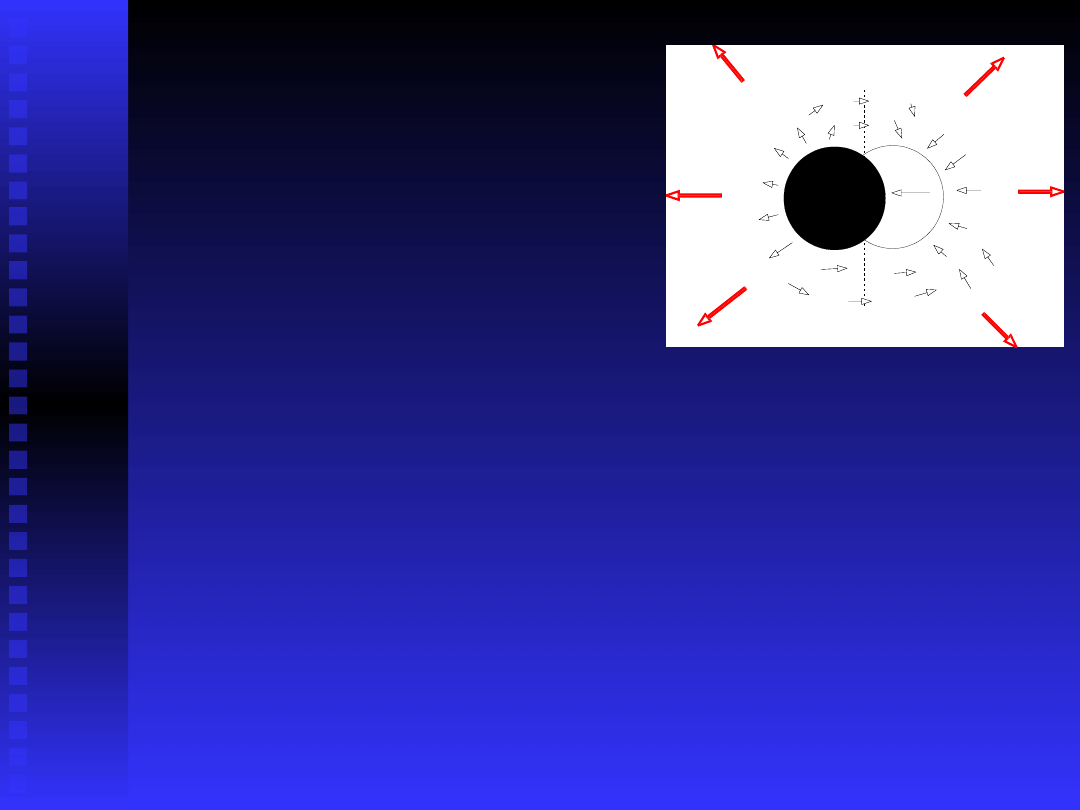
The acoustic dipole
(translating sphere)
The acoustic dipole is equi-
The acoustic dipole is equi-
valent to two monopoles 180
valent to two monopoles 180
deg out of phase.Therefore, at
deg out of phase.Therefore, at
equal distances from the centers of the monopoles,
equal distances from the centers of the monopoles,
sound pressures cancel (stippled line), i.e. sound
sound pressures cancel (stippled line), i.e. sound
radiates in a 'figure-eight'-pattern (red arrows).
radiates in a 'figure-eight'-pattern (red arrows).
Local flow field is shown by arrows. If wavelength is
Local flow field is shown by arrows. If wavelength is
large compared to sphere, sound emission is
large compared to sphere, sound emission is
'short-circuited' by local flow. Note that, unlike
'short-circuited' by local flow. Note that, unlike
the monopole the dipole local flow field is not
the monopole the dipole local flow field is not
aligned with the sound field.
aligned with the sound field.
Acoustic dipole -
animation
http://www.kettering.edu/~drussell/demos.html
The acoustic quadrupole
A quadrupole is two connected
A quadrupole is two connected
dipoles. The sound emission is
dipoles. The sound emission is
more complicated, and only an
more complicated, and only an
animation will be shown here:
animation will be shown here:
http://www.kettering.edu/~drussell/demos.html

Local flow vs. near/far
field
Traditionally, the local flow has been called a near-
Traditionally, the local flow has been called a near-
field effect. Near/far fields are not very precise
field effect. Near/far fields are not very precise
terms, however, (for one thing, ’near field’ is
terms, however, (for one thing, ’near field’ is
used for two different effects) and should be
used for two different effects) and should be
avoided for the following reasons:
avoided for the following reasons:
1) Animals have receptors for medium motion
1) Animals have receptors for medium motion
or sound pressure. Hence, any motion or sound
or sound pressure. Hence, any motion or sound
pressure whether originating from local flow or
pressure whether originating from local flow or
sound wave can stimulate the relevant
sound wave can stimulate the relevant
receptors - i.e. there are no specialized near-
receptors - i.e. there are no specialized near-
field/far field receptors.
field/far field receptors.

Local flow vs. Near/far
field 2
2) The rules of thumb for ’extension’ of the near
2) The rules of thumb for ’extension’ of the near
field (e.g. 1/6th wavelength) only hold for
field (e.g. 1/6th wavelength) only hold for
monopole sound emitters. For dipoles and
monopole sound emitters. For dipoles and
quadrupoles, the local flow continues to
quadrupoles, the local flow continues to
dominate at infinite distances at some
dominate at infinite distances at some
directions.
directions.
It is recommended to distinguish between the
It is recommended to distinguish between the
local hydrodynamic flow and the sound wave. It
local hydrodynamic flow and the sound wave. It
is also recommended to
is also recommended to
measure the medium
measure the medium
motion
motion
when working within a wavelength of
when working within a wavelength of
the sound emitter.
the sound emitter.

Manipulations of the
sound field
1. Local flow/sound considerations:
1. Local flow/sound considerations:
Most important for
Most important for
low frequencies
low frequencies
Underwater sound.
Underwater sound.
There is no way to avoid local flow generation by a
There is no way to avoid local flow generation by a
sound emitter.
sound emitter.
Move away from sound emitter (at least a wavelength)
Move away from sound emitter (at least a wavelength)
If you are interested in particle motion sensitivity
If you are interested in particle motion sensitivity
minimize sound emission of stimulator (use small
minimize sound emission of stimulator (use small
vibrating spheres or air puffs) and
vibrating spheres or air puffs) and
Calibrate the motion component directly
Calibrate the motion component directly

Standing wave tubes
In a standing wave, sound pressure
In a standing wave, sound pressure
and particle velocity are 90 deg out of
and particle velocity are 90 deg out of
phase, so distinct pressure and
phase, so distinct pressure and
velocity nodes form in a standing
velocity nodes form in a standing
wave tube. Such devices have
wave tube. Such devices have
traditionally been used to investigate
traditionally been used to investigate
whether ears responded to the
whether ears responded to the
pressure or velocity component of
pressure or velocity component of
sound
sound

Diffuse/free sound fields
For investigations of directional hearing it is
For investigations of directional hearing it is
desirable to avoid reflected components in the
desirable to avoid reflected components in the
sound field, i.e. to work in a free sound field.
sound field, i.e. to work in a free sound field.
The most obvious solution is an anechoic room
The most obvious solution is an anechoic room
with structures that absorb reflections.
with structures that absorb reflections.
Anechoic rooms are nearly always too small
Anechoic rooms are nearly always too small
(making it difficult to avoid reflections at low
(making it difficult to avoid reflections at low
frequencies)
frequencies)
Audiometric cabins (such as the IAC) are
Audiometric cabins (such as the IAC) are
sound- proof, but not really anechoic, at least
sound- proof, but not really anechoic, at least
not below 1000 Hz.
not below 1000 Hz.

Free sound fields
Reflections can be removed digitally:
Reflections can be removed digitally:
If the reflections do not overlap the
If the reflections do not overlap the
investigated structures’ impulse
investigated structures’ impulse
response, short transients can be
response, short transients can be
used to excite the structure A time
used to excite the structure A time
window is chosen that just contains
window is chosen that just contains
the impulse response and eliminates
the impulse response and eliminates
the echoes.
the echoes.

Loudspeakers:directivity,
radiation, baffles
Loudspeakers vary tremendously in
Loudspeakers vary tremendously in
the sound field they generate. It is up
the sound field they generate. It is up
to the experimenter to select/build
to the experimenter to select/build
omnidirectional speakers or very
omnidirectional speakers or very
directional ones depending on the
directional ones depending on the
question asked.
question asked.
The low-frequency radiation of
The low-frequency radiation of
speakers can be improved dramatically
speakers can be improved dramatically
by baffles.
by baffles.

Measuring the sound field
1) by animals:
1) by animals:
The two parameters of sound: Sound pressure is
The two parameters of sound: Sound pressure is
non-directional. Typical receivers are closed with
non-directional. Typical receivers are closed with
sound access from one side only (these receivers
sound access from one side only (these receivers
actually respond to the pressure difference across
actually respond to the pressure difference across
the membrane.
the membrane.
Medium motion is directional (albeit with 180 deg.
Medium motion is directional (albeit with 180 deg.
ambiguity. Simplest receivers are the diverse types
ambiguity. Simplest receivers are the diverse types
of sensory hairs with some kind of intrinsic
of sensory hairs with some kind of intrinsic
directionality. Note that combining a measure of
directionality. Note that combining a measure of
medium motion with pressure can resolve the 180
medium motion with pressure can resolve the 180
deg ambiguity, in far-field sound, at least.
deg ambiguity, in far-field sound, at least.
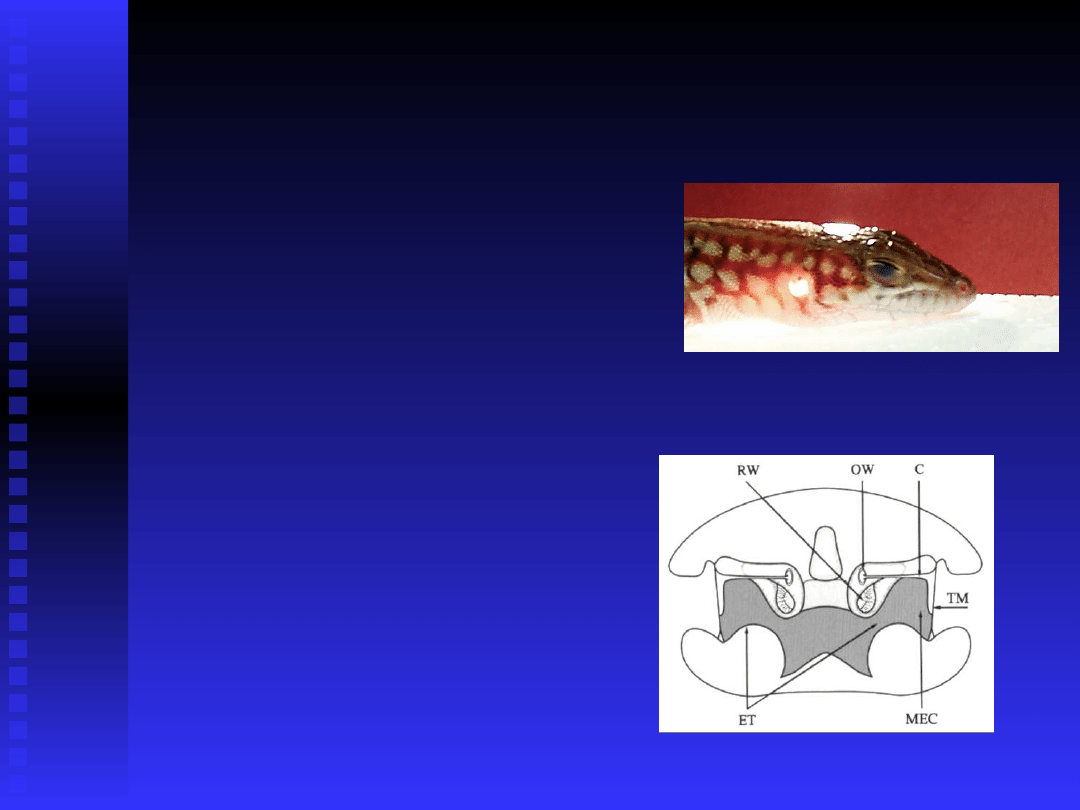
Measuring the sound field
2
Third type of receivers are
Third type of receivers are
the pressure-difference (or
the pressure-difference (or
–gradient) receivers. Here
–gradient) receivers. Here
sound can enter both sides
sound can enter both sides
of a membrane producing
of a membrane producing
cancellation when sound
cancellation when sound
pressures at the two sides
pressures at the two sides
have identical amplitudes
have identical amplitudes
and phases. These
and phases. These
receivers are only
receivers are only
directional in a narrow
directional in a narrow
frequency range.
frequency range.

Measuring the sound field
3
With instruments:
With instruments:
Sound pressure is measured with
Sound pressure is measured with
microphones that respond to the
microphones that respond to the
pressure gradient across a
pressure gradient across a
membrane. Pressure gradient
membrane. Pressure gradient
microphones can be constructed to
microphones can be constructed to
allow sound to enter both sides om
allow sound to enter both sides om
membrane.
membrane.

Measuring the sound field
4
Sound intensity measurements use two
Sound intensity measurements use two
(phase-matched) microphones or
(phase-matched) microphones or
hydrophones to estimate the pressure
hydrophones to estimate the pressure
gradient (and hence the particle velocity)
gradient (and hence the particle velocity)
and calculate the time average of p*v. This
and calculate the time average of p*v. This
measurement gives the active, radiating
measurement gives the active, radiating
sound emitted from the source.
sound emitted from the source.
Direct measurements of particle velocity is
Direct measurements of particle velocity is
difficult, since the methods at hand (hot
difficult, since the methods at hand (hot
wire anemometry, laser anemometry, PIV)
wire anemometry, laser anemometry, PIV)
only work at high sound levels.
only work at high sound levels.

Suggested reading
Beranek LL (1954) Acoustics. McGraw Hill
Beranek LL (1954) Acoustics. McGraw Hill
Fahy F (1995) Sound Intensity, 2.ed. Chapman and
Fahy F (1995) Sound Intensity, 2.ed. Chapman and
Hall
Hall
Gade S (1982) Sound Intensity, part 1: Theory.
Gade S (1982) Sound Intensity, part 1: Theory.
Brüel & Kjær Technical Review 3
Brüel & Kjær Technical Review 3
Kalmijn A (1988) Hydrodynamic and acoustic field
Kalmijn A (1988) Hydrodynamic and acoustic field
detection. In Atema J et al. (eds.) Sensory biology
detection. In Atema J et al. (eds.) Sensory biology
of aquatic animals. Springer, p. 83-130
of aquatic animals. Springer, p. 83-130
Larsen ON (1995) Acoustic equipment and sound
Larsen ON (1995) Acoustic equipment and sound
field calibration. In Klump GM et al (eds.) Methods
field calibration. In Klump GM et al (eds.) Methods
in comparative psychoacoustics. Birkhäuser
in comparative psychoacoustics. Birkhäuser
Verlag, p. 31-45
Verlag, p. 31-45
Document Outline
- Slide 1
- Slide 2
- Slide 3
- Slide 4
- Slide 5
- Slide 6
- Slide 7
- Slide 8
- Slide 9
- Slide 10
- Slide 11
- Slide 12
- Slide 13
- Slide 14
- Slide 15
- Slide 16
- Slide 17
- Slide 18
- Slide 19
- Slide 20
- Slide 21
- Slide 22
- Slide 23
- Slide 24
- Slide 25
- Slide 26
- Slide 27
- Slide 28
- Slide 29
- Slide 30
- Slide 31
- Slide 32
Wyszukiwarka
Podobne podstrony:
Lovstadt, Svensson Diffracted sound field from an orchestra pit
Ando An Evaluation Of The Effects Of Scattered Reflections In A Sound Field
Dance, Shield Modelling of sound ®elds in enclosed spaces with absorbent room surfaces
Farina Reproduction of auditorium spatial impression with binaural and stereophonic sound systems
Field of Glory Errata
Constructing the Field
Brain Sync Sound Healing Instructions
crc press cyber crime investigator 27s field guide
initial sound longAa
initial sound ch
initial sound Mm
initial sound Ww
initial sound Ll
initial sound longIi
initial sound Oo
initial sound Pp
PHILIPS SOUND
Improvements in Fan Performance Rating Methods for Air and Sound
więcej podobnych podstron