1 9 8 7
MANIFOLD AND EXHAUST SYSTEM
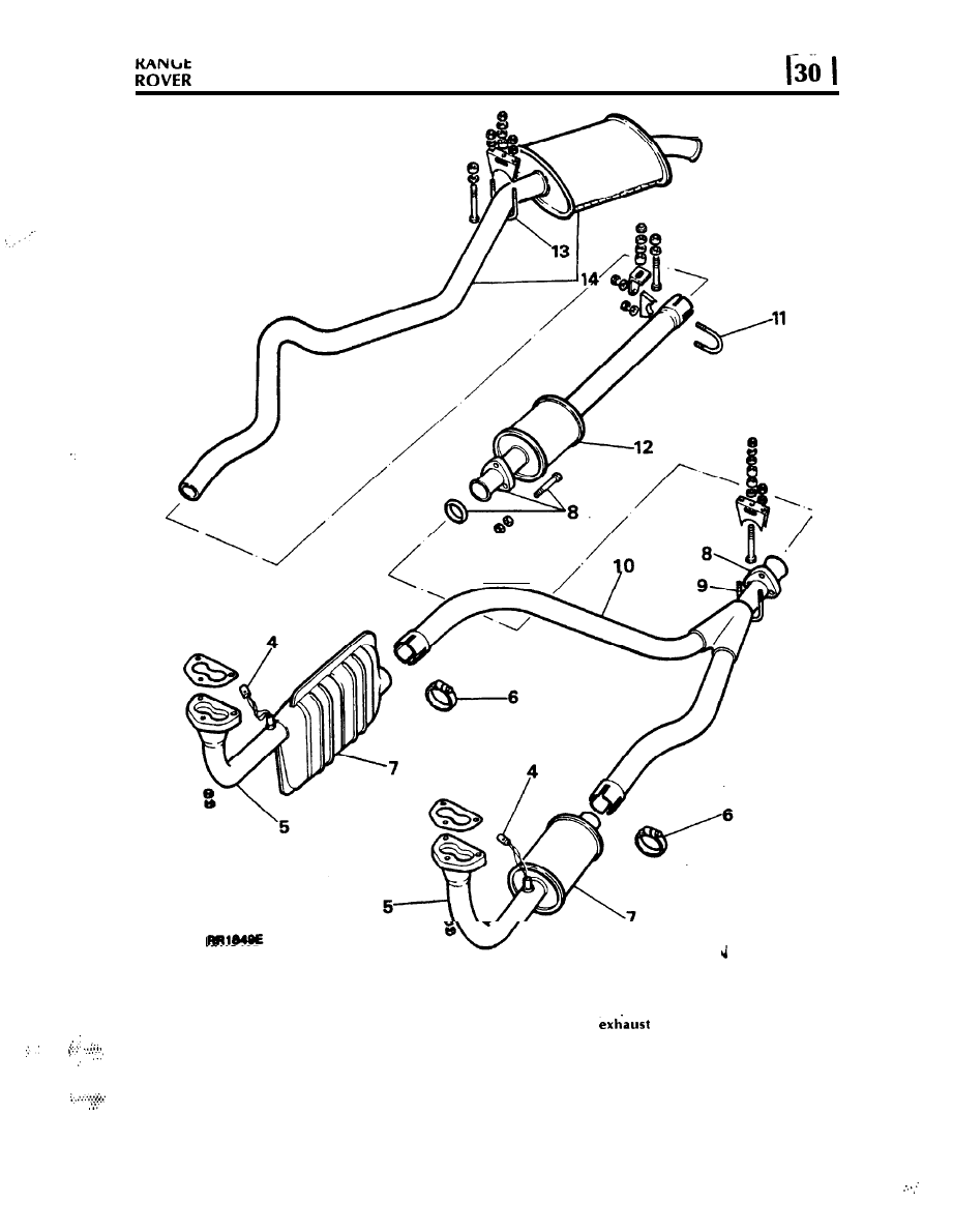
EXHAUST SYSTEM COMPLETE
EXHAUST SYSTEM COMPLETE
WARNING: To prevent personal injury occurring
f r o m a h o t
s y s t e m , D O N O T a t t e m p t t o
.
NOTE: Ensure that no exhaust leaks are evident
d i s c o n n e c t a n y o f t h e c o m p o n e n t s u n t i l a m p l e
in either a new or an old exhaust system, as this
time has elapsed to allow the exhaust system to
will affect vehicle performance, and contravene
cool.
Federal emission regulations.
C o n t i n u e d
REVISED: DEC. 87
1
MANIFOLD AND EXHAUST SYSTEM
Remove and refit
EXHAUST MANIFOLD
Removing
Remove and refit
Raise the vehicle on a suitable hoist and apply
the parking brake.
Left hand
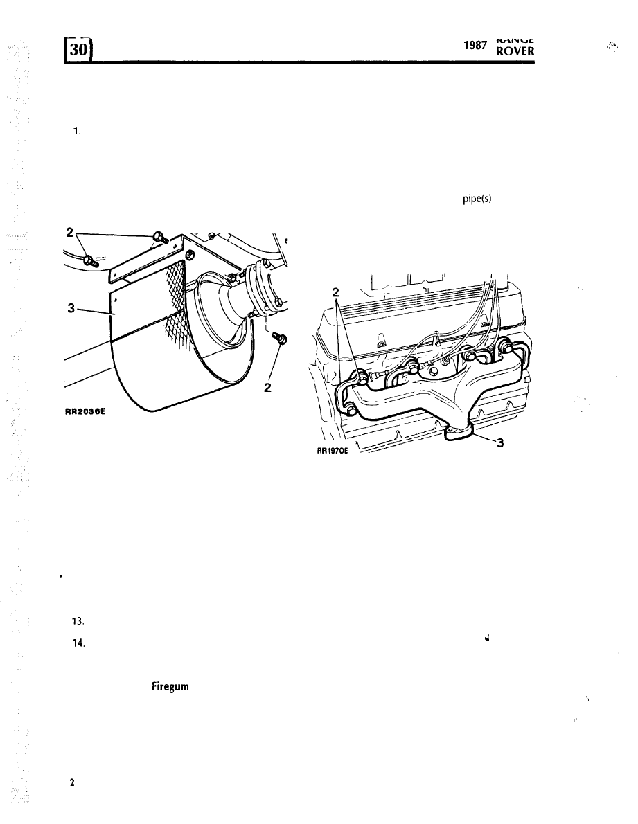
2. Remove the four fixings securing the grass
shield (if fitted) to the mounting bracket at the
centre catalyst.
Right hand
Removing
3. Withdraw the grass shield from the bracket.
1. Disconnect the front exhaust
from the
manifold(s).
2. Tap back the bolt locking tabs and remove the
eight bolts, lock tabs and washers.
3. Remove the manifold(s) and old gaskets.
4. Disconnect the electrical plugs from the
Lambda sensors.
5. Remove the nuts and disconnect the front
pipe(s) from the manifold(s) and remove the
gaskets.
6. Loosen the pinch bolt clamps securing the
front pipe to the intermediate pipe.
7. Withdraw the front pipe(s) with catalysts.
8. Remove three bolts securing the intermediate
pipe to the centre catalyst and withdraw the
doughnut.
Refitting
4. Ensure that the mating surfaces of the cylinder
head and exhaust manifold are clean and
smooth.
9. Remove the U-bolt from the pipe mounting
bracket.
5. Coat the threads of each bolt with anti-seize
compound.
10. Withdraw the intermediate pipe.
11. Remove the U-bolt securing the centre catalyst
to the main muffler.
6. Place the manifold and new gaskets in position
on the cylinder head and fit the securing bolts,
new lockplates and plain washers. The plain
washers are fitted between the manifold and
lockplates.
12. Withdraw the catalyst.
Remove the U-bolt from the tail pipe
mounting bracket.
Withdraw the tail pipe and rear muffler.
7. Evenly tighten the manifold bolts to the
correct torque, see torque values-section 06,
and bend over the lockplate tabs.
8. Reconnect the front exhaust pipe, using new
exhaust flange gaskets.
Refitting
NOTE: Apply
Putty, Part No. 15608
to all exhaust system joints with the
exception of the exhaust flange to manifold
flange where new gaskets should be fitted.
INTAKE MANIFOLD
15. Reverse the removal instructions.
The removal and refit of the intake manifold is
incorporated
in the Fuel Injection System,
Section 19.
. .
REVISED: DEC. 87
MANIFOLD AND EXHAUST SYSTEM
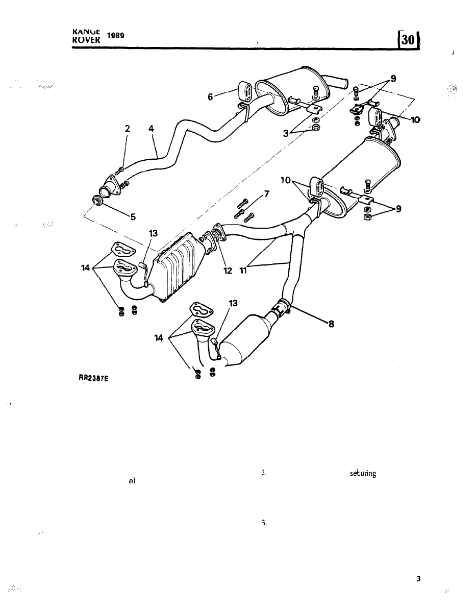
EXHAUST SYSTEM COMPLETE
NOTE: Ensure that no exhaust leaks are evident
in either a new or old exhaust system, as this
will affect vehicle performance, and contravene
Federal emission regulations.
W A R N I N G : T o p r e v e n t p e r s o n a l i n j u r y o c c u r r i n g
f r o m a h o t e x h a u s t s y s t e m , D O N O T a t t e m p t t o
d i s c o n n e c t a n y
t h e c o m p o n e n t s u n t i l a m p l e
time has elapsed to allow the exhaust system to
cool.
Remove and refit
Removing
Tail pipe and rear muffler
1 .
3 .
4 .
Raise the vehicle on a suitable hoist and apply
the parking brake.
Remove the three bolts
the tail pipe
assembly to the intermediate pipe assembly.
Remove the bolt securing the rear mounting
bracket. to the chassis.
Maneuver the tail pipe over the rear axle and
remove from the vehicle.
R e t a i n t h e d o u g h n u t f r o m t h e i n t e r m e d i a t e
pipe for reassembly.
C o n t i n u e d
ADDITION: SEPT. 88

6. Detach the rubber from the tailpipe and
hanger.
intermediate pipe and centre muffler
7. Remove the three bolts securing the right
hand branch of the intermediate pipe to the
right hand catalyst.
8. Release the pinch bolt clamp securing the left
hand branch of the intermediate pipe to the
left hand catalyst and slide the clamp along
the pipe.
9. Remove the bolts securing the front and rear
hanger brackets to the chassis.
10. Detach the rubbers from the main muffler
assembly and hangers.
11. Carefully separate the intermediate pipes from
the front downpipes.
12. Retain the doughnut from the right hand joint.
Front downpipes
13. Disconnect both Lambda sensor multiplugs.
Remove the nuts and release the front
downpipes from the manifolds, discard the
gaskets.
Refitting
lf the original system is being refitted, examine
the system for damage and general condition
renew sections as necessary.
16. Clean any previous putty from the doughnuts
and exhaust pipe joints.
17. Fit NEW gaskets to the manifold joint face.
NOTE: Apply exhaust sealer to all exhaust system
joints with the exception of the exhaust flange
to manifold flange.
18. Reverse the removal instructions.
Examine a new or original system for leaks and
ensure that the system does not foul any
underbody components. If exhaust leaks or
interference exists loosen the joints reseal and
reset as necessary.
4
ADDITION: SEPT. 88

MANIFOLD AND EXHAUST SYSTEM
EXHAUST SYSTEM COMPLETE
Remove and refit
To improve sealing and accuracy of assembly, 1990
model year vehicles have a new two piece exhaust
Removing
NOTE: Ensure that no exhaust leaks are evident
in either a new or old exhaust system, as this
will affect vehicle performance.
Raise the vehicle on a
ramp. apply the
parking brake.
C a t a l y s t v e h i c l e s o n l y :
Disconnect the two
lambda sensor wiring connectors.
Remove the two bolts securing the rear
exhaust
assembly to
the front exhaust
assembly.
Remove the nuts and release the front
downpipes fromt the manifolds. Discard the
gaskets.
W A R N I N G : T o p r e v e n t p e r s o n a l i n j u r y o c c u r r i n g
f r o m a h o t e x h a u s t s y s t e m , D O N O T a t t e m p t t o
. .
. ,
d i s c o n n e c t a n y o f t h e c o m p o n e n t s u n t i l a m p l e
time has elapsed to allow the exhaust system to
cool.
ADDITION: SEPT. 89
5

MANIFOLD AND EXHAUST SYSTEM
5. Lower the front exhaust assembly, retrieving
the doughnut from the joint.
NOTE: The assistance of a second mechanic
i s r e q u i r e d f o r r e m o v i n g a n d r e f i t t i n g t h e
rear exhaust assembly.
6. Remove the bolts securing the three hanger
brackets to the chassis. Lower the exhaust
a s s e m b l y o n t o t h e r e a r a x l e . D e t a c h t h e
rubbers from the hanging brackets.
7. Place extended axle stands underneath the
chassis, in front of the chassis mounted rear
towing brackets.
8. Lower the hoist until the vehicle weight is
supported securely on the stands.
9. Lower the hoist until the rear shock absorbers
are almost fully extended.
10. Move the rear exhaust to a diagonal position
with the centre silencer to the right of the
vehicle.
1 1 . F a c i n g t h e r e a r o f t h e v e h i c l e , t w i s t t h e
assembly counter-clockwise until it clears the
rear axle.
12. Remove the rear exhaust assembly from the
vehicle.
Refitting
13. Position the rear exhaust assembly over the
rear axle in a diagonal position, as for
removing.
14. Twist the assembly clockwise until it is in the
mounting position.
15. Reverse the removing instructions
to 9.
using
new manifold gaskets and applying
exhaust sealer to the system joint.
16. Examine the system for leaks and ensure that
t h e s y s t e m d o e s n o t f o u l a n y u n d e r b o d y
components. Rectify as necessary.
1990
6
ADDITION: SEPT. 89
Wyszukiwarka
Podobne podstrony:
Range Rover, 2006 2009
Range Rover Sport 2005 2013
Range Rover, 1994 2002
range rover 2004my owners handbook right hand drive vehicles only
Range Rover 2005 Sport
Range Rover Evoque, 2011
Range Rover 2005
Range Rover, 2002 2006
Range Rover 2006
Range Rover, 2009
Range Rover Discovery TD6 2005
range rover
OPERATOR MANUAL LONG RANGE SNIPER RIFLE CALIBER 50, M107
Rotax Rave 2 Instrukcja i Ustawienie Zaworu EXHAUST POWER VALVE INSTALLATION GUIDE Rave 2 Owner Ma
PANsound manual
als manual RZ5IUSXZX237ENPGWFIN Nieznany
hplj 5p 6p service manual vhnlwmi5rxab6ao6bivsrdhllvztpnnomgxi2ma vhnlwmi5rxab6ao6bivsrdhllvztpnnomg
BSAVA Manual of Rabbit Surgery Dentistry and Imaging
więcej podobnych podstron