
Abstraction-Based Intrusion Detection In
Distributed Environments
PENG NING
North Carolina State University
and
SUSHIL JAJODIA and XIAOYANG SEAN WANG
George Mason University
Abstraction is an important issue in intrusion detection, since it not only hides the difference
between heterogeneous systems, but also allows generic intrusion-detection models. However, ab-
straction is an error-prone process and is not well supported in current intrusion-detection systems
(IDSs). This article presents a hierarchical model to support attack specification and event abstrac-
tion in distributed intrusion detection. The model involves three concepts: system view, signature,
and view definition. A system view provides an abstract interface of a particular type of informa-
tion; defined on the instances of system views, a signature specifies certain distributed attacks or
events to be monitored; a view definition is then used to derive information from the matches of a
signature and presents it through a system view. With the three elements, the model provides a
hierarchical framework for maintaining signatures, system views, as well as event abstraction. As
a benefit, the model allows generic signatures that can accommodate unknown variants of known
attacks. Moreover, abstraction represented by a system view can be updated without changing
either its specification or the signatures specified on its basis. This article then presents a decen-
tralized method for autonomous but cooperative component systems to detect distributed attacks
specified by signatures. Specifically, a signature is decomposed into finer units, called detection
tasks, each of which represents the activity to be monitored on a component system. The compo-
nent systems (involved in a signature) then perform the detection tasks cooperatively according
to the “dependency” relationships among these tasks. An experimental system called CARDS has
been implemented to test the feasibility of the proposed approach.
Categories and Subject Descriptors: D.4.6 [Operating Systems]: Security and Protection—Inva-
sive software (e.g., viruses, worms, Trojan horses); D.4.7 [Operating Systems]: Organization and
Design—Distributed systems; K.6.5 [Management of Computing and Information Systems]:
Security and Protection
General Terms: Security
Additional Key Words and Phrases: Cooperative information systems, heterogeneous systems, in-
trusion detection, misuse detection
Authors’ addressess: P. Ning, Department of Computer Science, North Carolina State University,
Raleigh, NC 27695-7534; email: ning@csc.ncsu.edu; S. Jajodia and X. S. Wang, MSN4A4, Center
for Secure Information Systems, George Mason University, 4400 University Drive, Fairfax, VA
22030-4444; emails:
{jajodia, xywang}@gmu.edu.
Permission to make digital or hard copies of part or all of this work for personal or classroom use is
granted without fee provided that copies are not made or distributed for profit or direct commercial
advantage and that copies show this notice on the first page or initial screen of a display along
with the full citation. Copyrights for components of this work owned by others than ACM must be
honored. Abstracting with credit is permitted. To copy otherwise, to republish, to post on servers,
to redistribute to lists, or to use any component of this work in others works, requires prior specific
permission and/or a fee. Permissions may be requested from Publications Dept, ACM Inc., 1515
Broadway, New York, NY 10036 USA, fax
+1 (212) 869-0481, or permissions@acm.org.
C
°
2001 ACM 1094-9224/01/1100–0407 $5.00
ACM Transactions on Information and System Security, Vol. 4, No. 4, November 2001, Pages 407–452.

408
•
P. Ning et al.
1. INTRODUCTION
Intrusion detection has been studied for at least two decades since the An-
derson’s report [Anderson 1980]. As a second line of defense for computer and
network systems, intrusion-detection systems (IDSs) have been deployed more
and more widely along with intrusion-prevention techniques such as password
authentication and firewalls. Research on intrusion detection is still rather ac-
tive due to the quick pace of change in information technology.
Intrusion-detection techniques can be classified into two categories: misuse
detection and anomaly detection. Misuse detection looks for signatures (i.e., the
explicit patterns) of known attacks, and any matched activity is considered
an attack. Examples of misuse-detection techniques include the State Tran-
sition Analysis Toolkit (STAT) [Ilgun et al. 1995] and colored Petri automata
(CPA) [Kumar 1995]. Misuse detection can detect known attacks effectively,
though it usually cannot accommodate unknown attacks. Anomaly detection
models the subject’s (e.g., a user’s or a program’s) behaviors, and any signif-
icant deviation from the normal behaviors is considered the result of an at-
tack. Examples of anomaly-detection models include the statistical models used
in NIDES (NIDES/STAT) [Javits and Valdes 1993] and HAYSTACK [Smaha
1988]. Anomaly detection has the potential to detect unknown attacks; how-
ever, it is not as effective as misuse detection for known attacks. In practice,
both misuse detection and anomaly detection are often used as complemen-
tary components in IDSs (e.g., EMERALD [Porras and Neumann 1997], JiNao
[Chang et al. 2001; Wu et al. 2001]).
Abstraction, as explained in Webster’s New World Dictionary of American
English [Neufeldt 1988], is the “formation of an idea, as of the qualities or prop-
erties of a thing, by mental separation from particular instances or material
objects.” Abstraction in intrusion detection is considered important, mainly due
to two reasons. First, the systems being protected as well as the IDSs are usu-
ally heterogeneous. In particular, a distributed system often consists of different
types of component systems such as Windows and UNIX machines. Abstraction
thus becomes necessary to hide the differences between these component sys-
tems and allow intrusion detection in distributed systems. For example, IETF’s
intrusion detection message exchange format (IDMEF) provides an abstract
data model and common message format for different types of IDSs to under-
stand each other [Curry and Debar 2001]. Second, abstraction is often used
to hide irrelevant details, so that IDSs can avoid unnecessary complexity and
focus on essential information. As an example, JiNao uses an event abstrac-
tion module to convert low-level IP packets into abstract events (for link state
advertisement) so that it can have more concise and generic representations of
attacks [Chang et al. 2001; Jou et al. 2000; Wu et al. 2001].
However, abstraction in intrusion detection has not been well supported.
The most common way to use abstraction is as a preparation process, and
the abstraction process is performed ad hoc. Such approaches may cause some
problems as the IDSs and our knowledge of intrusions evolve. For example, in
the Mitnick attack described in Northcutt [1999], the attacker first launches
a SYN flooding attack to prevent a trusted host from accepting incoming TCP
ACM Transactions on Information and System Security, Vol. 4, No. 4, November 2001.

Abstraction-Based Intrusion Detection
•
409
connection requests (i.e., SYN packets), and then tries to connect to another
host using the IP address and TCP port being flooded as source IP and source
port. To detect such an attack in a misuse-detection system, a human user may
specify an attack signature that involves a SYN flooding event and the related
TCP connection. However, this signature has a potential problem: The attacker
may use other ways to disable one or all of the TCP ports of the trusted host
and launch a similar attack that is not covered by the signature. To cover such
attacks, the user has to write one signature for each possible way the attacker
can disable a TCP port of the trusted host. In addition, when new ways of dis-
abling a TCP port are discovered, the user needs to input additional signatures
into the system.
Certainly, an experienced user may choose a smarter way. Instead of using
the SYN flooding event in the signature, he (or she) may abstract it to an
event that can disable a TCP port on the trusted host. Such a signature is
generic enough to accommodate variants of the aforementioned Mitnick attack.
However, there is no framework to support such an attempt in existing systems.
The user may, for example, write a program (e.g., the event abstraction module
in JiNao [Chang et al. 2001; Jou et al. 2000; Wu et al. 2001]) to abstract all events
(including SYN flooding attack) that can disable a TCP port. Unfortunately,
when a new way of disabling a TCP port is discovered, the user will have to
modify the program to reflect the new information. Such a task is certainly not
a pleasant one for an administrator.
The above example suggests that (1) abstraction is an error-prone process
and (2) there is not enough support for effective and efficient abstraction
in current IDSs. To address these issues, we propose a hierarchical model
for attack specification and event abstraction. Our model is extended from
the misuse-detection model proposed in ARMD [Lin 1998; Lin et al. 1998],
which was developed to deal with the portability of misuse signatures for host-
based IDSs.
There are three essential concepts in our model: system view, (misuse) sig-
nature, and view definition. A system view provides an abstract representa-
tion of a particular type of observable information, which includes an event
schema and a set of predicates. An event schema specifies the attributes that
describe the abstract events on a system view, while the predicates tell the re-
lationship among system entities. For example, we may have a system view,
TCPDOSAttacks, that represents TCP-based denial of service (DOS) attacks,
where the event schema specifies the IP address and port number being at-
tacked and the predicates indicate the severity of the attack. Although there
may be different types of such attacks, the system view, TCPDOSAttacks, can
hide the difference between them and provide an abstract representation.
A signature is a distributed event pattern that represents a distributed at-
tack on the instances of system views. With system views providing abstract
views of the information, the signatures can represent the attacks in a generic
way. For example, we may have a signature for the Mitnick attack based on
the system view, TCPDOSAttacks (among others). As a result, the signature
will still be applicable even if the attacker uses other methods instead of SYN
flooding to disable a TCP port of the trusted host.
ACM Transactions on Information and System Security, Vol. 4, No. 4, November 2001.

410
•
P. Ning et al.
View definition is the critical concept that helps us exceed the limitation of
the previous approaches. A view definition is used to derive information from
the matches of a signature and present it through a system view. With view
definition, our model provides a hierarchical framework for event abstraction.
For example, we may have a system view IPPacket that provides information
for IP packet events. On the basis of IPPacket, we may first define signatures
for various TCP-based DOS attacks such as SYN flooding attacks and Ping of
Death (see Kendall [1999] for details of these attacks) and then abstract them as
TCP-based DOS attacks on TCPDOSAttacks using view definitions. As a result,
detection of the above attacks will generate events on TCPDOSAttacks. The
introduction of view definition provides a toolkit to unify attack specification
and event abstraction in the same framework.
Having the three elements, our model allows a flexible and dynamic way
of maintaining signatures and system views as well as event abstraction. For
example, when we initially specify the system view TCPDOSAttacks, we may
only have knowledge of some attacks such as SYN flooding and Ping of Death.
Certainly, we can specify it with whatever we know, and even describe signa-
tures (e.g., signature for the Mitnick attack) using TCPDOSAttacks, once it is
specified. However, if new types of TCP-based DOS attacks are later discovered,
we do not need to change either the specification of the system view itself or the
signatures (e.g., the Mitnick attack) that are described on its basis. Instead, we
only need to specify signatures and corresponding view definitions for the new
discovery.
One important problem that we have to solve for our model is how to de-
tect the specified attacks. The techniques proposed in ARMD [Lin 1998] can
be slightly extended to address host-based intrusion detection; however, new
techniques are needed for distributed intrusion detection, since it requires dis-
tribution and coordination mechanisms, which is beyond ARMD.
Several distributed IDSs have been proposed to address similar issues. Early
distributed IDSs for small-scale systems usually have all the information sent
to a central place (possibly after being filtered). For example, ASAX prepro-
cesses the audit data in distributed component systems and sends necessary
information to a central place for analysis [Mounji 1997, 1995]. However, such
a method does not scale well to large distributed systems, because the infor-
mation collected from a large distributed system may exceed the capacity of
any single system, and the intrusion-detection-related messages will take the
network bandwidth.
Later systems (e.g., EMERALD [Porras and Neumann 1997] and GrIDS
[Staniford-Chen et al. 1996]) adopt a hierarchical framework that organizes
IDSs into a fixed hierarchy and requires low-level IDSs send designated infor-
mation to high-level IDSs. For example, EMERALD organizes IDSs for individ-
ual hosts under the IDSs for departments, which are under an IDS for the entire
enterprise [Porras and Neumann 1997]. The hierarchical approach scales bet-
ter than the aforementioned centralized one. However, it is not always the most
efficient way to detect distributed attacks. For example, if two IDSs that are far
from each other in terms of the hierarchy are designated to detect a known dis-
tributed attack, the data sent by them may have to be forwarded several times
ACM Transactions on Information and System Security, Vol. 4, No. 4, November 2001.

Abstraction-Based Intrusion Detection
•
411
(to higher-level IDSs) before they can be finally correlated. Indeed, the two IDSs
can communicate more efficiently if they directly talk to each other. Thus, it is
worth further research to seek more efficient alternatives to the hierarchical
approach.
In this article, we present an approach to organizing autonomous but cooper-
ative component systems to detect distributed attacks. Our approach is based
on dependency among the distributed events in a signature. Unlike the hier-
archical approach, our approach organizes the cooperative IDSs according to
the intrinsic relationships between the distributed events involved in attacks,
and, as a result, an IDS needs to send a piece of information to another IDS
only when the information is essential to detect the attacks. To examine the
feasibility of our approach, we develop an architecture to support our approach
and implement an experimental system called Coordinated Attacks Response
& Detection System (CARDS).
The contribution of this article is twofold. First, we provide a framework for
distributed attack specification and event abstraction by extending the origi-
nal ARMD model. In this framework, abstraction is considered as an ongoing
process, and signatures and view definitions can be used to update the seman-
tics of a system view without changing the its specification and the signatures
specified on its basis. As a result, signatures in our model can potentially ac-
commodate unknown variants of known attacks. Although the specification
of attack signatures and the choice of right abstraction still partially depend
on the user’s skill, this framework provides guidance and alleviates the bur-
den of writing and maintaining signatures. Second, we develop a decentralized
approach to detect distributed attacks specified using the revised model. By
considering the intrinsic relationship between the distributed events in a sig-
nature, we decompose a signature into smaller units called detection tasks that
can be executed in different IDSs; moreover, we develop a distributed algorithm
to coordinate the detection tasks so that the IDSs can cooperatively detect the
attacks.
The rest of this article is organized as follows. The next section discusses
related work. Section 3 presents the basic model, which is extended from the
misuse-detection model in ARMD to accommodate new requirements in dis-
tributed environments. Section 4 further extends the basic model and presents
the hierarchical model for attack specification and event abstraction. Section 5
presents a decentralized approach to detect distributed attacks specified by our
model. Section 6 gives a heuristic approach to generating execution plans used
by decentralized detection. Section 7 briefly describes an experimental system
named CARDS for the approaches proposed in this article. Section 8 concludes
and points out some future research directions.
2. RELATED WORK
Our work falls into the research domain of detecting intrusions distributed
over multiple systems, including distributed intrusion-detection systems and
other related techniques. A survey of the early work on intrusion detection
is given in Mukherjee et al. [1994], and an excellent overview of the current
ACM Transactions on Information and System Security, Vol. 4, No. 4, November 2001.

412
•
P. Ning et al.
intrusion-detection techniques and related issues can be found in a recent book
[Bace 2000].
Early distributed intrusion-detection systems collected audit data from dis-
tributed component systems but analyzed them in a central place (e.g., DIDS
[Snapp et al. 1991], ISM [Heberlein et al. 1992], NADIR [Hochberg et al. 1993],
NSTAT [Kemmerer 1997] and ASAX [Mounji 1997, 1995]). Although audit data
are usually reduced before being sent to the central analysis unit, the scalability
of such systems is limited due to the centralized analysis.
Recent systems paid more attention to the scalability issue (e.g., EMERALD
[Porras and Neumann 1997], GrIDS [Staniford-Chen et al. 1996], AAFID
[Spafford and Zamboni 2001], and CSM [White et al. 1996]). EMERALD adopts
a recursive framework in which generic building blocks can be deployed in a
highly distributed manner [Porras and Neumann 1997]. Both misuse detec-
tion and statistical anomaly detection are used in EMERALD. GrIDS aims
at large distributed systems and performs intrusion detection by aggregat-
ing computer and network information into activity graphs which reveal the
causal structure of network activity [Staniford-Chen et al. 1996]. AAFID is a
distributed intrusion-detection platform, which consists of four types of compo-
nents: agents, filters, transceivers, and monitors [Spafford and Zamboni 2000].
These components can be organized in a tree structure, where child and parent
components communicate with each other. AAFID emphasizes the architecture
aspect of distributed intrusion detection; detailed mechanisms for performing
distributed intrusion detection are not addressed. JiNao is an IDS that detects
intrusions against network routing protocols [Chang et al. 2001; Jou et al. 2000;
Wu et al. 2001]. The current implementation of JiNao focuses on the OSPF (open
shortest path first) routing protocol. A distinguished feature of JiNao is that it
can be integrated into existing network management systems. It is mentioned
that JiNao can be used for distributed intrusion detection [Jou et al. 2000; Wu
et al. 2001]; however, no specific mechanisms have been provided for doing so.
In terms of the way distributed intrusion detection is performed, our ap-
proach differs from these systems as follows: While our approach decomposes
and coordinates distributed event collection and analysis according to the in-
trinsic relationships between the distributed events, the aforementioned sys-
tems either have no specific way to coordinate different IDSs (e.g., JiNao [Jou
et al. 2000; Wu et al. 2001]), or rely on some predefined hierarchical organiza-
tion, which is usually determined by administrative concerns (e.g., EMERALD
[Porras and Neumann 1997], GrIDS [Staniford-Chen et al. 1996]). Compared
to the hierarchical approach, our approach has the advantage that the compo-
nent IDSs can exchange necessary information without forwarding it along the
hierarchy.
NetSTAT is an application of STAT [Ilgun et al. 1995] to network-based in-
trusion detection [Vigna and Kemmerer 1999, 1998]. Based on the attack sce-
narios and the network fact modeled as a hypergraph, NetSTAT automatically
chooses places to probe network activities and applies the state transition anal-
ysis. Our approach is similar to NetSTAT, in the sense that both approaches
can decide what information needs to be collected in various places. However,
our approach also differs from NetSTAT in the following ways. NetSTAT is
ACM Transactions on Information and System Security, Vol. 4, No. 4, November 2001.

Abstraction-Based Intrusion Detection
•
413
specific to network-based intrusion detection, while our approach is generic to
any kind of distributed intrusion detection. Moreover, NetSTAT collects the
network events in a distributed way, but analyzes them in a central place. In
contrast, our approach analyzes the distributed events in a decentralized way;
that is, the events are analyzed as being collected in various places.
Event abstraction has long been recognized as an important issue in in-
trusion detection as well as in many other areas. It not only removes irrel-
evant details, but also hides the difference between heterogeneous systems.
Several systems have adopted components for event abstraction. ARMD ex-
plicitly brought up the concept of abstract systems to provide the abstract rep-
resentation of system information [Lin 1998; Lin et al. 1998]. AAFID introduces
filters as a data abstraction layer for intrusion-detection agents [Spafford and
Zamboni 2000]. JiNao adopts an event abstraction module to transform low-
level network activities into high-level events [Jou et al. 2000; Wu et al. 2001].
(There are other examples; however, we do not enumerate them here). Our ap-
proach here further extends these ideas by providing a hierarchical framework
for event abstraction. In particular, we view event abstraction as a dynamic
process (instead of a preparatory stage as in most of the previous approaches).
The advantage is that we can update the semantics of event abstraction without
changing either its specification or the signatures defined on its basis, and thus
have generic signatures that can accommodate the variants of known attacks.
Several approaches have been proposed to represent known attacks. Among
the earliest are the rule-based languages such as P-BEST [Lindqvist and Porras
1999] and RUSSEL [Mounji 1997, 1995]. Later work includes the state tran-
sition analysis toolkit (STAT) [Ilgun 1993; Ilgun et al. 1995] and its extension
POSTAT [Ho et al. 1998], the colored PetriNet automaton (CPA) [Kumar 1995;
Kumar and Spafford 1994], and JiNao finite state machine (JFSM) [Jou et al.
2000; Wu et al. 2001]. The general philosophy of these approaches is to make the
representation mechanisms easy to use but yet be able to represent most of the
known attacks (if not all). Our representation mechanism can be considered as
a variation of STAT or CPA, which removes the explicit states from the attack
patterns. A new feature of our method allows events to be extracted from sig-
natures so that attack (or event) patterns can be specified in a hierarchical way.
Moreover, our representation mechanism allows us to decompose a distributed
attack pattern into smaller units that can be executed in a distributed manner.
Common intrusion detection framework (CIDF) is an effort that aims at
enabling different intrusion detection and response (IDR) components to inter-
operate and share information and resources [Kahn et al. 1998; Porras et al.
1998]. CIDF views IDR systems as composed of four kinds of components that
communicate via message passing: event generators (E-boxes), event analyzers
(A-boxes), event databases (D-boxes), and response units (R-boxes). A communi-
cation framework and a common intrusion specification language are provided
to assist interoperation among CIDF components [Feiertag et al. 2000; Kahn
et al. 1998]. Several efforts have tried to improve the CIDF components’ ability
to interoperate with each other: The intrusion detection intercomponent adap-
tive negotiation (IDIAN) protocol helps cooperating CIDF components to reach
an agreement as to each other’s capabilities and needs [Feiertag et al. 2000];
ACM Transactions on Information and System Security, Vol. 4, No. 4, November 2001.

414
•
P. Ning et al.
MADAM ID uses CIDF to automatically get audit data, build models, and dis-
tribute signatures for novel attacks so that the gap between the discovery and
the detection of new attacks can be reduced [Lee et al. 2000; Lee and Stolfo
2000]; finally, the query facility for CIDF enables CIDF components to request
specific information from each other [Ning et al. 2000a, 2000b].
IETF’s Intrusion Detection Working Group (IDWG) has been working on
data formats and exchange procedures for sharing information among IDSs,
response systems, and management systems. XML has been chosen to provide
the common format and an Intrusion Detection Message Exchange Format (ID-
MEF) has been defined in an Internet draft [Curry and Debar 2001]. IDWG
uses the blocks extensible exchange protocol (BEEP) as the application proto-
col framework for exchanging intrusion-detection messages between different
systems [Rose 2001]; an intrusion detection exchange protocol (IDXP) is spec-
ified as a BEEP profile [Feinstein et al. 2001], and a tunnel profile is provided
for different systems to exchange messages through firewalls [New 2001].
We view CIDF, IDMEF (IDXP) and their extensions as complementary to
ours. First, in terms of representation, CIDF, IDMEF (IDXP), and their exten-
sions provide common message formats and exchange procedures for IDSs to
interoperate and understand each other, while our work provides a framework
for event abstraction as well as specification of known intrusion patterns. Sec-
ond, neither CIDF nor IDWG provides any specific way to coordinate different
IDSs (indeed, as standards, they try to avoid any specific mechanism). Though
MADAM ID enables different IDSs to collaborate with each other, the collabo-
ration is limited to collecting audit data for new attacks and distributing newly
discovered signatures [Lee et al. 2000]. In contrast, our approach decomposes
a signature for a distributed attack into smaller units, distributes these units
to different IDSs, and coordinates these IDSs to detect the attack.
The Hummer project is intended to share information among different IDSs
[Frincke et al. 1998]. In particular, the relationships between different IDSs
(e.g., peer, friend, manager/subordinate relationships) and policy issues (e.g.,
access control policy, cooperation policy) are studied, and a prototype system,
HummingBird, was developed to address these issues. However, the Hummer
project is to address the general data-sharing issue; what information needs
to be shared and how the information is used are out of its scope. In contrast,
our decentralized detection approach addresses the issue of efficiently detect-
ing specific attacks; it is able to specify what information is needed from each
site and how the information is analyzed. Indeed, our decentralized detection
approach can be combined with the Hummer system to fully take advantage of
its data collection capability.
Our work is based on the host-based misuse-detection system, ARMD [Lin
1998; Lin et al. 1998]. This article further extends the result of ARMD in sev-
eral ways. First, the attack specification model is extended to allow the rep-
resentation of attacks across multiple systems. In particular, our model as-
sumes interval-based events rather than point-based events; thus, not only
event records directly derived from audit trails but also compound events are
accommodated. Moreover, the revised model adopts the notion of negative event
and can take into account exceptional situations (see Section 3.2). Second, the
ACM Transactions on Information and System Security, Vol. 4, No. 4, November 2001.

Abstraction-Based Intrusion Detection
•
415
revised model allows hierarchical specification of event patterns, which not
only provides a way to model distributed attacks, but also a framework for
automatic event abstraction. Finally, we develop a decentralized approach to
detecting distributed attacks.
There are many other related works such as various anomaly-detection mod-
els (e.g., NIDES/STAT [Javits and Valdes 1993], HAYSTACK [Smaha 1988]),
data mining approaches (e.g., MADAM ID [Lee et al. 1999; Lee and Stolfo 2000],
ADAM [Barbara et al. 2001]), various tracing techniques (e.g., DECIDUOUS
[Chang et al. 1999; 2000], thumbprinting [Staniford-Chen 1996]), and embed-
ded sensors [Kerschbaum et al. 2000]. We consider these techniques as comple-
mentary to ours presented in this article.
3. THE BASIC MODEL
In this section we present our basic attack specification model, which is ex-
tended from the model in ARMD [Lin 1998; Lin et al. 1998]. A critical concept
of our model is system view; each system view provides an abstract interface for
one particular type of information. Attack patterns, which we call misuse sig-
natures, are then specified as distributed event patterns on the basis of system
view instances.
System views reflect the notion of abstraction in our model. We consider
abstraction as an ongoing process instead of a preparatory stage. That is, a
system view can be extended without changing the signatures defined on the
basis of its instances. A direct advantage is that the signatures defined in our
model are generic and can accommodate new attacks to a certain degree.
In the rest of this section, we describe our basic model, i.e., how we repre-
sent system views and attacks. In the next section, we present a hierarchical
framework for attack specification as well as event abstraction based on the
basic model.
3.1 System View and Event History
Intuitively, a system view provides an abstract representation of one particular
type of information provided by a system. The system underlying a system view
may be one single host, a network segment, or a distributed system consisting
of several hosts.
Both event information and relationships among system entities are pro-
vided through a system view. Events represent what has happened or is hap-
pening in the system, while relationships among system entities represent the
system state at certain times. For instance, the fact that two files are owned by
the same user can be represented by a relationship same owner between them.
The time when an event occurs is intrinsic to the event. In distributed envi-
ronments, the intrusion detection related events are usually not instantaneous
in terms of time. For example, a TCP connection could span several hours. To
accommodate such events, we consider that each event has a duration, and
associate an interval-based timestamp with it. Notationwise, each timestamp
is denoted in the form of [begin time, end time], representing, respectively, the
starting and ending points of the time interval.
ACM Transactions on Information and System Security, Vol. 4, No. 4, November 2001.

416
•
P. Ning et al.
Similar to ARMD [Lin 1998; Lin et al. 1998], we use dynamic predicates
to represent the relationships among system entities. A dynamic predicate is a
predicate with time as one of its arguments. For example, the dynamic predicate
same owner[t](file x, file y), which represents whether files file x and file y
have the same owner is True if and only if the owners of file x and file y are
the same at time t. Note that “static” or regular predicates are special cases of
dynamic predicates.
The notion of system view is formally stated as follows.
Definition 1.
A system view is a pair (EvtSch, PredSet), where EvtSch
(called event schema) is a set of event attribute names, each with an associ-
ated domain of values, and PredSet is a set of dynamic predicate names. An
event e on (EvtSch, PredSet) is a tuple on EvtSch with a timestamp [begin time,
end time].
A system view serves as an interface of the information of interest. Though
a system view itself is fixed once defined, the information provided through it
can be extended. For example, when we define a system view for TCP/IP-based
denial of service (DOS) attacks, we may abstract the system view from Teardrop
and Land attacks (Please refer to Kendall [1999] for details of the attacks).
However, we may later discover SYN flooding and Ping Of Death attacks, which
are also TCP/IP-based DOS attacks. Such newly discovered information can be
provided directly through the existing system view without changing either the
system view specification or the signatures already defined on the basis of its
instances.
Note that begin time and end time are implicit attributes of the event
schema, which collectively represent the timestamps of events on the system
view. The information provided through a system view, including both event
and state information, is formalized as an event history on the corresponding
system view.
Definition 2.
An event history on the system view (EvtSch, PredSet) con-
sists of (1) a finite set of events
{e
1
,
. . . , e
m
} on (EvtSch, PredSet) and (2) an
instantiation of the dynamic predicate names in PredSet such that for each
p in PredSet and each time point t, when an event occurs, p is instantiated
as a regular predicate, denoted p[t](x
1
,
. . . , x
k
) (i.e., for each instantiation of
x
1
,
. . . , x
k
, p[t](x
1
,
. . . , x
k
) gives True or False).
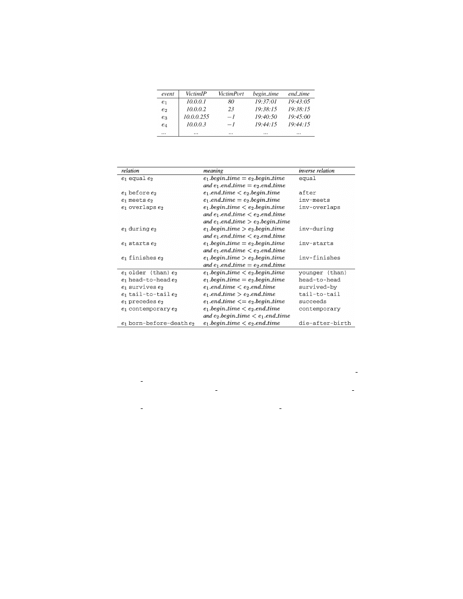
Example 1.
A network monitor that reports DOS attacks that disable one
or all the TCP ports of a host may have a system view TCPDOSAttacks
=
(EvtSch1,
∅), where EvtSch1 = {VictimIP, VictimPort}. Each DOS attack is re-
ported as an event on (EvtSch1,
∅). The domain of VictimIP is the set of IP
addresses, and the domain of VictimPort is the set of all TCP ports plus
−1.
VictimPort being
−1 means that all TCP ports (of the host) are disabled. An
event history on TCPDOSAttacks is shown in Figure 1.
As we discussed earlier, TCPDOSAttacks may be defined when we only know,
for example, Teardrop and Land attacks. When we later discover new types of
DOS attacks, for example, SYN flooding attack, we can still reuse the previously
specified TCPDOSAttacks.
ACM Transactions on Information and System Security, Vol. 4, No. 4, November 2001.
Abstraction-Based Intrusion Detection
•
417
Fig. 1. An event history on the system view TCPDOSAttacks.
Fig. 2. The qualitative temporal relationships between two events.
As another example, a host may have a system view LocalTCPConn
=
(EvtSch2, PredSet2) for the TCP connections observed on the local host, where
EvtSch2
= {SrcIP, SrcPort, DstIP, DstPort} and PredSet2 = {LocalIP[t](var IP),
Trust[t](var host)
}. The domains of the attributes are clear from the names. The
dynamic predicate LocalIP[t](var IP) evaluates to True if and only if var IP is
an IP address belonging to the local host at time t, and the dynamic predicate
Trust[t](var host) evaluates to True if and only if var host is trusted by the local
host at time t. Examples of event history on LocalTCPConn are omitted.
3.1.1 Qualitative Temporal Relationships Between Events. The represen-
tation and reasoning about the qualitative temporal relationships between
interval-based events have been studied extensively by the AI community
[Allen 1983; Freska 1992]. With these relationships, we can provide a more
concise representation of the patterns among events.
Here we quote the thirteen relationships between intervals [Allen 1983] and
the eleven relationships between semiintervals [Freksa 1992] as the qualitative
relationships between events. Figure 2 shows the relationships between two
interval-based events e
1
and e
2
. The inverse relation in the figure refers to
ACM Transactions on Information and System Security, Vol. 4, No. 4, November 2001.

418
•
P. Ning et al.
the relation derived by switching the positions of the events in the original
relation. For example, the inverse relation of e
1
before e
2
is e
1
after e
2
, which
is equivalent to e
2
before e
1
.
Complex qualitative (temporal) relationships between two events can be
represented by logical combinations of the above relations. For example, the
situation that events e
1
and e
2
do not overlap in time can be represented by
(e
1
before e
2
) or (e
1
after e
2
), or simply e
1
( before or after) e
2
. In the follow-
ing, we take advantage of these qualitative temporal relationships to describe
attack signatures.
3.2 Misuse Signatures
Misuse signatures are event patterns that represent intrusive activities across
multiple systems. With system views as abstract representations of the un-
derlying systems, a misuse signature is defined as a pattern of events on
the instances of these system views. Specifically, a signature is a labeled di-
rected graph. Each node in the graph corresponds to an observable event
on a particular system view, and each labeled arc to a qualitative tempo-
ral relationship between the two nodes (events) involved in the arc. Events
matched to the nodes must satisfy certain conditions, which are built into
the model by associating a timed condition with each node (in a way similar
to ARMD).
There are two kinds of events, positive events and negative events, due to their
different “roles” in attacks. Positive events are the events that are necessary
and critical for an attack. In other words, positive events are those necessary
steps that an attacker cannot miss in order to launch the attack. Let us look at
the Mitnick attack described in the introduction. In order to attack host B, the
attacker first initiates a SYN flooding attack to prevent a TCP port of host A,
which is trusted by B, from accepting any connection requests. (See Schuba et al.
[1997] for detailed information about SYN flooding attacks). During the SYN
flooding attack, the attacker tries to establish a TCP connection to B pretending
(by IP spoofing) to be from the port being flooded. If the attacker succeeds, he
can do whatever host B allows host A to do, since the attacking computer is
mistaken for A. In this attack, the SYN flooding attack against host A and the
TCP connection to host B from the attacking computer are positive events, since
the attack will not succeed without them.
However, the existence of positive events does not always imply an attack. For
example, even if we observe two positive events, a SYN flooding attack against
host A in the network traffic and the corresponding TCP connection on host B
during the SYN flooding attack, they do not constitute a Mitnick attack if the
TCP connection is indeed initiated from host A (rather than from the attacking
computer). In other words, if we also observe the same TCP connection on host A,
then the TCP connection is just a normal connection during the SYN flooding
attack rather than a part of the Mitnick attack. We call the TCP connection
observed on host A a negative event, which serves as counter-evidence of attacks.
Thus, negative events are such events that if they coexist with the positive
events, the positive events do not constitute an attack.
ACM Transactions on Information and System Security, Vol. 4, No. 4, November 2001.

Abstraction-Based Intrusion Detection
•
419
Negative events have appeared in different forms in other models. For ex-
ample, CPA uses (negative) invariants to specify what must not happen during
an attack: that is, the specified attack does not occur if the associated invari-
ant is violated (matched) [Kumar 1995; Kumar and Spafford 1994]. Negative
events are important to reduce false alarms; however, they should be used with
caution. The signature writer should be certain that the existence of negative
events indeed indicates the nonexistence of attacks. Otherwise, the attacker
may bypass the IDS by intentionally creating negative events.
In order to model the patterns among multiple events, we use variables to
help specify timed conditions. A variable is assigned an event attribute value
from one node and then used in a timed condition associated with another node.
We also use
ε as a variable for an event. A timed condition is formally defined
as follows:
Definition 3.
A timed condition on a system view (EvtSch, PredSet) is
a Boolean formula with atoms being either (1) comparisons among con-
stants, variables, and event attribute names in EvtSch; or (2) of the form
p[
ε.begin time](a
1
,
. . . , a
k
),
p[
ε.end time](a
1
,
. . . , a
k
), (
∃t ∈ [ε.begin time,
ε.end time]) p[t](a
1
,
. . . , a
k
), or (
∀t ∈ [ε.begin time, ε.end time]) p[t](a
1
,
. . . , a
k
),
where p is a dynamic predicate name in PredSet and a
1
,
. . . , a
k
are constants,
variables, or event attribute names in EvtSch. A timed condition evaluates to
True or False when the variables are replaced with constants and
ε with an
event.
We are now ready to formally define the concept of a misuse signature.
Definition 4.
Given a set of system view instances S
= {(EvtSch
1
, PredSet
1
),
. . . , (EvtSch
k
, PredSet
k
)
}, a misuse signature (or signature) on S is a 7-tuple (N,
E, SysView, Label, Assignment, TimedCondition, PositiveNodes), where
(1) (N, E) is a directed graph;
(2) SysView is a mapping that maps each node n in N to a system view instance
in S;
(3) Label is a mapping that maps each arc in E to a qualitative temporal rela-
tionship between two events;
(4) Assignment is a mapping that maps each node n in N to a set of assignments
of event attributes in the system view SysView(n) to variables (denoted as
variable :
= attribute name) such that each variable appears in exactly one
assignment in the signature;
(5) TimedCondition is a mapping that maps each n in N to a timed condition
on SysView(n) such that all variables in the timed condition appear in some
assignments specified by (4); and
(6) PositiveNodes
6= ∅ is a subset of N.
A misuse signature is an event pattern that represents an intrusive activity
over a set of systems represented by the system view instances. The pattern
is described by a set of events and the constraints that these events must sat-
isfy. Given a signature (N, E, SysView, Label, Assignment, TimedCondition,
PositiveNodes), the set N of nodes represents the set of events involved in the
ACM Transactions on Information and System Security, Vol. 4, No. 4, November 2001.
420
•
P. Ning et al.
Fig. 3. The signature for the Mitnick attack.
pattern; the edges and the labels associated with the edges, which are speci-
fied by the mappings E and Label, encode the qualitative temporal relation-
ships between these events; the mapping TimedCondition specifies the condi-
tions that each event must satisfy; and the mapping Assignment determines
attributes that are used in some timed conditions. The set PositiveNodes of
nodes represents the positive events necessary to constitute an attack, while
(N
− PositiveNodes) represents the negative events that contribute information
to filter out false alarms.
Note that we use the qualitative temporal relationships between events to
help specify misuse signatures. However, in order to represent quantitative
temporal relationships between events, we have to assign timestamps to vari-
ables and specify them in timed conditions. For example, if we require that
two events e
1
and e
2
start within 10 seconds, we can assign e
1
.begin time to
a variable t and then specify e
2
’s timed condition as
|t − e
2
.begin time| < 10
(assuming that the time is measured in seconds).
For a better illustration, we pictorially represent a misuse signature as a
labeled graph. Given a signature Sig
= (N, E, SysView, Label, Assignment,
TimedCondition, PositiveNodes), the components N and E are represented by a
directed graph, where the nodes in PositiveNodes have a solid boundary and the
other nodes have dotted boundaries, the components SysView, Assignment, and
TimedCondition are represented by a system view, a set of assignments, and a
timed condition associated with each node; the component Label is represented
by a label associated with each arc; and the system view instances underlying
the signature are given by a list of declarations of system view instances. An
example of misuse signatures follows.
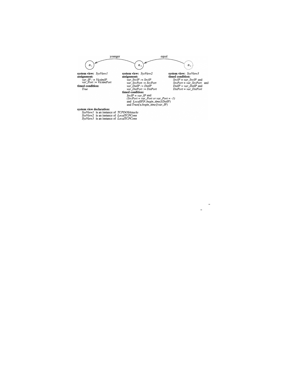
Example 2.
This example shows a signature of the aforementioned Mitnick
attack. It’s worth noting that though the original attack involves a SYN flooding
attack, an attacker can actually use other methods to disable one or all of the
TCP ports of host A and achieve the same effect. Thus, the signature for the
Mitnick attack should use something more abstract than SYN flooding attacks.
Figure 3 shows a generic version of the signature for the Mitnick attack.
The signature involves three system view instances: an instance of the system
ACM Transactions on Information and System Security, Vol. 4, No. 4, November 2001.

Abstraction-Based Intrusion Detection
•
421
view TCPDOSAttacks and two instances of LocalTCPConn. (The system views
TCPDOSAttacks and LocalTCPConn are described in Example 1.) This signa-
ture defines a generic pattern for the Mitnick attack. Nodes n
1
and n
2
represent
positive events. Node n
1
represents a DOS attack on an instance of the system
view, TCPDOSAttacks (e.g., a network monitor), and node n
2
represents a local
TCP connection event observed on one host, say host B. The timed condition
associated with n
2
says that it is from the port being attacked (or any port
if all TCP ports are disabled) and destined to host B, and the attacked host
is trusted by B. The labeled arc (n
2
, n
1
) restricts that this TCP connection
should occur after the begin time of the DOS attack. Representing a nega-
tive event, node n
3
stands for a TCP connection observed on the victim host
of the DOS attack, say host A. The timed condition of n
3
and the labeled arc
(n
3
, n
2
) indicate that this TCP connection should be the same as the one rep-
resented by n
2
. This signature says that a TCP connection from a port being
attacked by DOS (or any port of a host all TCP ports of which were disabled)
is a Mitnick attack, if the host being attacked by DOS does not have the same
connection.
The signature in Figure 3 reflects the basic idea describing the signature for
the Mitnick attack. It can also be revised to take into account that events n
1
and n
2
are often close to each other in time (in addition to the specification that
n
2
is younger than n
1
). Such a signature would be easier to execute, since we
do not have to consider a DOS attack and a TCP connection if they are far from
each other in time.
Now we clarify the semantics of a misuse signature by formally defining
what it matches.
Definition 5.
Let Sig
= (N, E, SysView, Label, Assignment, TimedCondi-
tion, PositiveNodes) be a signature on the set of system view instances S
= {(EvtSch
1
, PredSet
1
),
. . . , (EvtSch
k
, PredSet
k
)
}, and for each 1 ≤ i ≤ k, let
H
i
= {e
i,1
,
. . . , e
i,m
i
} be an event history on the system view (EvtSch
i
, PredSet
i
).
For a subset N
s
of N, a mapping
π : N
s
→ {e
1,1
,
. . . , e
1,m
1
, e
2,1
,
. . . , e
2,m
2
,
. . . ,
e
k,1
,
. . . , e
k,m
k
} is said to be a match of N
s
on
H
1
,
. . . , H
k
if the following condi-
tions are satisfied:
(1) for each node n in N
s
,
π(n) = e is an event on the system view associated
with n and event attribute values of e are assigned to variables according
to the assignments associated with n;
(2) for each arc (n
1
, n
2
) in E such that n
1
and n
2
are in N
s
, if
π(n
1
)
= e
i
and
π(n
2
)
= e
j
and (n
1
, n
2
) is mapped to a qualitative temporal relationship
·R·
by the mapping Label, then e
i
· R · e
j
; and
(3) for each node n in N
s
with a timed condition, if
π(n) = e, then the timed
condition is True with
ε replaced with e and the variables with the values
assigned in (1).
A match
π of PositiveNodes on H
1
,
. . . , H
k
is said to be a match of Sig if (1) N
=
PositiveNodes, or (2) N
6= PositiveNodes, and there does not exist a match π
0
of
N such that
π and π
0
are the same for nodes in PositiveNodes.
ACM Transactions on Information and System Security, Vol. 4, No. 4, November 2001.
422
•
P. Ning et al.
Fig. 4. Events on the system views.
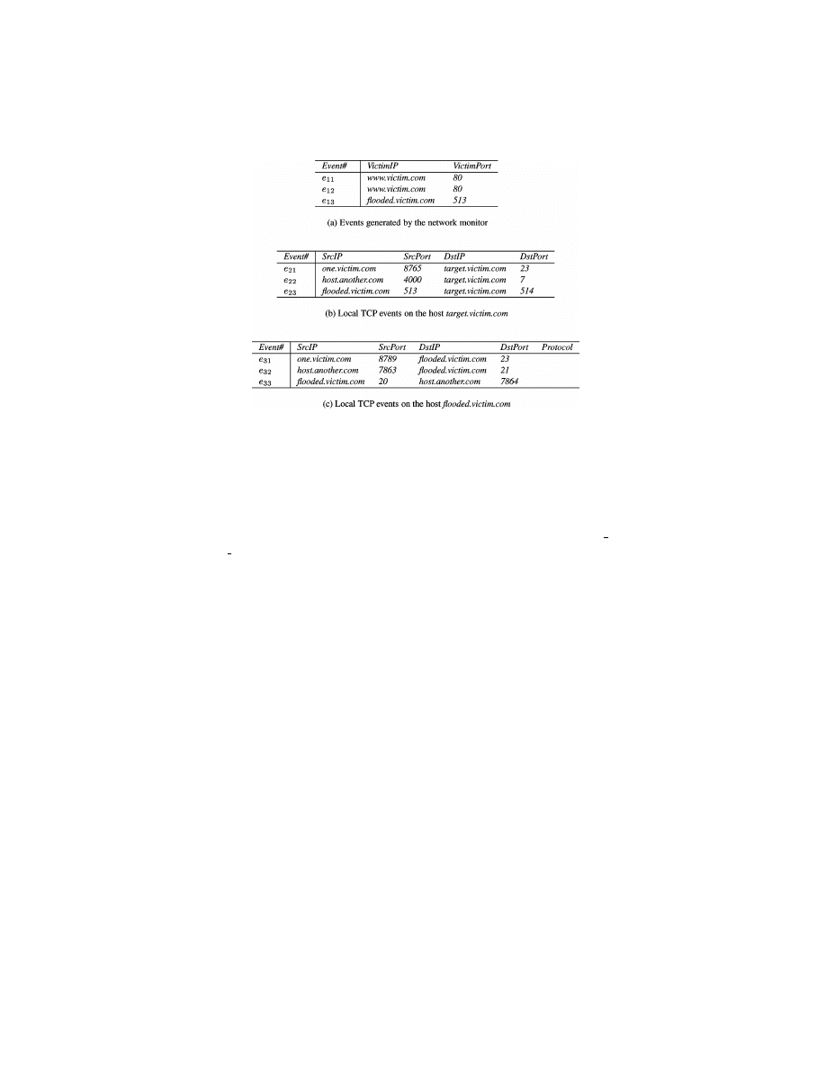
Example 3.
Suppose the network monitor in Example 2 has detected
the DOS attacks shown in Figure 4(a). (For simplicity, all timestamps are
omitted.) Also, suppose the hosts target.victim.com and flooded.victim.com have
TCP connection events shown in Figure 4(b) and 4(c), and target.victim.com
trusts flooded.victim.com (i.e., for all time point t, Trust[t](flooded.victim.com)
=
True). Suppose event e
23
is younger than event e
13
(i.e., e
13
.begin time <
e
23
.begin time). Then e
13
and e
23
satisfy all the conditions specified for nodes n
1
and n
2
. In addition, there does not exist any event on the host flooded.victim.com
that satisfies the conditions for node n
3
along with e
13
and e
23
. Thus, events e
13
and e
23
constitute a match of the signature. In other words, an instance of the
Mitnick attack is detected.
Nodes in a signature represent events on system views; therefore, in the
following discussion, we use nodes and events interchangeably.
4. DERIVING SYSTEM VIEWS FROM SIGNATURES:
A HIERARCHICAL MODEL
In this section we extend the basic model described in Section 3 to derive infor-
mation from the matches of signatures and present it through (possibly exist-
ing) system views. Such a derivation provides a way to extract (or aggregate)
information from the events that match the corresponding signatures, and thus
provides a more concise view of what has happened or is happening in the sys-
tems. As a result, our model allows signatures to be specified hierarchically,
since we can both describe signatures on the basis of system views and derive
system views from signatures.
There are several benefits of this extension. First, it reduces the complexity
of specifying signatures if the corresponding attacks can be decomposed into
logical steps (or components). Having the ability to hierarchically define signa-
tures allows a user to decompose a complex attack into logical components and
ACM Transactions on Information and System Security, Vol. 4, No. 4, November 2001.

Abstraction-Based Intrusion Detection
•
423
resolve them separately, and thus allows a divide and conquer strategy in the
signature specification process. Second, this approach provides a framework
for (event) abstraction. A hierarchy of system views and signatures provides
a way to abstract compound as well as aggregated information. Third, the
framework is dynamic and flexible. With system views as the foundation of
signatures, we can specify a signature on the basis of some system view in-
stances and later extend the system views without changing the specifica-
tions of either the system views or the signature. The derivation of an ex-
isting system view makes the abstraction represented by the system view a
dynamic process.
4.1 View Definition
Intuitively, we derive the information on a system view (called the derived
system view) from the matches of a signature in two steps.
Step (1). For each combination of events that match the signature, we take
the necessary information from them by assigning their attribute values to the
variables (indicated by the assignments). In other words, the selected attribute
values of an event are assigned to the variables if the event corresponds to a
positive node in a match. As a result, we can consider that each signature has
a relation whose attributes are the variables that appear in the assignments
associated with positive nodes, and each tuple in this relation consists of the
attribute values assigned to the variables in a match. We call the schema of
such a relation the matched view, and the information provided through the
matched view the match history of the signature. For example, the signature
of the Mitnick attack (shown in Figure 3) has a matched view whose schema
is (var IP, var Port, var SrcIP, var SrcPort, var DstIP, var DstPort), and the
tuples in this view will be the corresponding IP addresses and port numbers
involved in Mitnick attacks.
Step (2). We apply a function to process the matched history. The function
takes the tuples on the matched view as input and outputs events on the derived
system view. In particular, we identify a special class of functions that can be
executed in real time. That is, the function can be applied to a match of the
signature once it is detected. The events (on the derived system view) generated
this way correspond to the compound events represented by the detection of
signatures. For simplicity, we choose a subset of the dynamic predicates in the
underlying system views as the predicate set in the new one. An easy extension
could be to use logical combinations of the underlying dynamic predicates in
the derived system view.
In the following, we first formally define the notions of matched view and
matched history, then formalize the derivation of system views from signatures
as view definition.
Definition 6.
Let Sig
= (N, E, SysView, Label, Assignment, TimedCondi-
tion, PositiveNodes) be a signature on a set of system view instances S
=
{(EvtSch
1
, PredSet
1
),
. . . , (EvtSch
k
, PredSet
k
)
}. The matched view of Sig de-
rived from S, denoted (V), is a relation schema that consists of all the vari-
ables appearing in the assignments associated with the nodes in PositiveNodes.
ACM Transactions on Information and System Security, Vol. 4, No. 4, November 2001.

424
•
P. Ning et al.
Moreover, for each i, 1
≤ i ≤ k, let H
i
be an event history on (EvtSch
i
, PredSet
i
).
Then the matched history of Sig derived from
H
1
,
. . . , H
k
is a relation on (V) that
consists of one tuple t for each match of Sig on
H
1
,
. . . , H
k
, and the attribute
values of t are the values assigned to the variables in the match.
Definition 7.
Given a set S of system view instances, a view definition on
S is a 4-tuple (Sig, EvtSch, PredSet, f ), where
(1) Sig is a signature on S;
(2) EvtSch is a set of event attribute names, each with an associated domain
of values;
(3) PredSet is a subset of all the dynamic predicates appearing in S;
(4) f is a function that takes tuples of the matched view of Sig and outputs
tuples on EvtSch with interval-based timestamps.
The system view (EvtSch, PredSet) is called the system view derived by the
view definition, or simply derived system view.
A view definition (Sig, EvtSch, PredSet, f ) derives a system view on the basis
of the signature Sig. EvtSch specifies the event schema of the derived system
view, PredSet indicates the dynamic predicates inherited from the underlying
system views, and f describes how the matches of Sig are transformed into
events on EvtSch.
A critical component of a view definition is the function f . A special class
of function f is to postprocess the matches of the signature and generate a
compound event for each match. Typically, such a function f takes a match of
Sig, selects some attributes of interest, and presents them through the derived
system view. Information extracted this way may be used for high-level attack
correlation or intrusion response. For simplicity, we use an SQL query of the
form SELECT-FROM-WHERE, which is targeted to a single instance of the
matched view, to specify such a function. Note that using a simplified SQL
query does not imply that we have to use a SQL engine or DBMS; it can be
executed by simply taking a match once it is detected, evaluating the condition
in the WHERE clause, and renaming the variables of interest. Such queries
can be executed at the time when the matches of the signatures are detected,
and thus support real-time processing of the detection results.
However, SQL queries (even in unrestricted forms) are not expressive
enough; some event-processing semantics cannot be expressed using such
queries. For example, aggregation in terms of a sliding time window cannot be
expressed using SQL. An alternative approach is to use rule-based languages
to describe the function f
. Rule-based languages are more expressive than
SELECT-FROM-WHERE SQL statements; however, they cannot cover all pos-
sible event-processing semantics, either. For example, both P-BEST [Lindqvist
and Porras 1999] and RUSSEL [Mounji 1997; Mounji et al. 1995] depend on
external functions to extend their expressiveness. In addition, unlike SELECT-
FROM-WHERE SQL statements, which can be executed by evaluating con-
ditions and choosing/renaming attributes, rule-based languages require addi-
tional mechanisms to execute the rules.
ACM Transactions on Information and System Security, Vol. 4, No. 4, November 2001.
Abstraction-Based Intrusion Detection
•
425
Fig. 5. The view definition for deriving SYN flooding events from TCP packets.
Additional work is required to clarify what representation mechanisms are
needed to specify the function f of a view definition. However, since our focus
here is the framework of signature specification and event abstraction, we con-
sider f as a customizable blackbox and use SELECT-FROM (V)-WHERE for
some special cases.
Example 4.
Suppose we modify the signature Mitnick in Figure 3 by associ-
ating additional assignments var tm1 :
= begin time and var tm2 := end time to
nodes n
1
and n
2
, respectively. We can have a view definition MitnickAttacks
=
(Mitnick,
{Attack, VictimHost, VictimPort, TrustedHost}, {Trust[t](var host)}),
where Mitnick is the revised signature and Query is defined by the following
SQL statement.
SELECT ’Mitnick’ AS Attack, var DstIP AS VictimHost, var DstPort AS
Victim-Port, var SrcIP AS TrustedHost, var tm1 AS begin time, var tm2
AS end time FROM (V )
The system view derived by MitnickAttacks is (
{Attack, VictimHost,
VictimPort, TrustedHost
}, {Trust[t](var host)}).
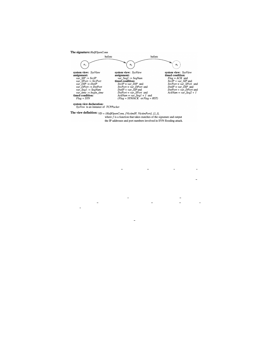
Example 5.
We consider a view definition that aggregates low-level TCP/IP
packet events into compound events representing SYN flooding attacks on the
system view TCPDOSAttacks (discussed in Example 1). Suppose the TCP/IP
packet information is provided through a system view TCPPacket
= (EvtSch,
∅), where EvtSch = {SrcIP, SrcPort, DstIP, DstPort, SeqNum, AckNum, Flag}.
These attributes represent the source address, the source port, the destination
address, the destination port, the sequence number, the acknowledge number,
and the flag associated with each packet. The domain of Flag is the set of
valid TCP flags, including SYN, SYN/ACK, ACK, RST, etc. The domains of
other attributes are clear from the names. (This system view can be directly
generated by tools such as tcpdump.)
Figure 5 shows the signature HalfOpenConn and the view definition VD
that defines the derived system view on the basis of HalfOpenConn. Node n
1
ACM Transactions on Information and System Security, Vol. 4, No. 4, November 2001.

426
•
P. Ning et al.
represents a SYN packet that initiates a TCP connection, and node n
2
repre-
sents a SYN/ACK packet or a RESET packet that responds to the SYN packet.
Both node n
1
and n
2
represent positive events. The negative node n
3
represents
an ACK packet that finalize a TCP three-way handshake. Thus, a match of Half-
OpenConn indicates either a half-open connection or a connection reset during
the TCP three-way handshake. The component f is a function (or procedure)
that takes the matches of HalfOpenConn as input and outputs the IP address,
TCP port, and the timestamp of SYN flooding attacks. One way to implement
f is to use a sliding time window and report a TCPDOSAttack (which is a SYN
flooding attack in this case) if the half-open connections against a certain TCP
port exceeds a certain threshold.
The reader may have noticed that some view definitions (e.g., the one shown
in Example 5) may introduce delays into the system. For instance, in Example 5,
to correctly generate interval-based events for SYN flooding attacks, the func-
tion f cannot output an event until the attack completes (for example, when the
number of half-open connections to a certain port drops below a certain thresh-
old). There is a dilemma in such delays. On the one hand, derived events with
correct timestamps are essential in reasoning about the attacks, which implies
that we may have to tolerate the delays. On the other hand, such delays have
negative impact on intrusion detection: The system may miss the opportunity
to respond to some attacks.
One possible way to alleviate this situation is to split each interval-based
event into a start event and a stop event. As a result, the attacks that only in-
volve the starting point of long events can be detected more promptly. However,
we only consider fully generated events here, and leave such an approach as
possible future work.
We call the information that a derived system view extracts or aggregates
from the underlying event histories a derived event history, which is formally
defined as follows:
Definition 8.
Let VD
= (Sig, EvtSch, PredSet, f ) be a view definition on a
set of system view instances S
= {(EvtSch
1
, PredSet
1
),
. . . , (EvtSch
k
, PredSet
k
)
}
and for 1
≤ i ≤ k, let H
i
be an event history on (EvtSch
i
, PredSet
i
). Then the
event history on (EvtSch, PredSet) derived from
H
1
,
. . . , H
k
consists of
(1) a set of events that f outputs by taking as input the matched history of Sig
derived from
H
1
,
. . . , H
k
; and
(2) the instantiation (in
H
1
,
. . . , H
k
) of the dynamic predicate names in PredSet.
Each event in the derived event history is called a derived event.
Example 6.
Consider the view definition shown in Example 4. Suppose the
event histories on the system view instances underlying this view definition
are the same as in Example 3 (see Figure 4). Then, based on the discussion in
Example 3, the events in the derived event history are shown in Figure 6, and
Trust[t](var host) evaluates to True if var host is trusted by the victim host at
time t.
ACM Transactions on Information and System Security, Vol. 4, No. 4, November 2001.
Abstraction-Based Intrusion Detection
•
427
Fig. 6. Events in the derived history.
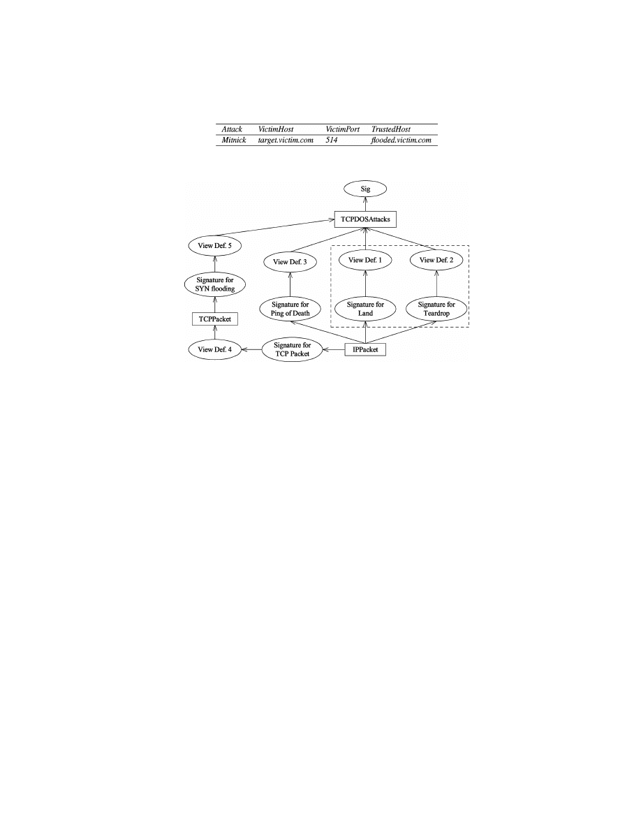
Fig. 7. A hierarchy of system views and signatures.
The introduction of view definition allows a hierarchical organization of sys-
tem views and signatures. Such a hierarchical model not only provides a frame-
work for attack specification and event abstraction, but also ensures that ab-
straction becomes a dynamic and ongoing process. Figure 7 shows a hierarchy
of system views, signatures, and view definitions. Notice that such a hierarchy
may evolve along time. For example, when we initially specify the system view,
TCPDOSAttacks, we may only be aware of two types of such attacks: Land
and Teardrop (see Kendall [1999] for details). Thus, we may derive information
on TCPDOSAttacks from IPPacket using signatures for Land and Teardrop
and the corresponding view definitions, as shown in the dashed box in Fig-
ure 7. Certainly, signatures can be specified on the basis of TCPDOSAttacks
once it is defined. However, we may later discover other TCP-based DOS at-
tacks, e.g., Ping of Death and SYN flooding attacks [Kendall 1999]. If this hap-
pens, we can use signatures and view definitions (e.g., the signatures and view
definitions outside of the dashed box in Figure 7) to derive more events on
TCPDOSAttacks without changing either the specification of TCPDOSAttacks
itself or the signatures defined on its basis. In other words, we can gradually
change the semantics of system views and signatures without changing their
specifications. As a result, the signatures specified in our model are generic and
can potentially accommodate new attacks.
As illustrated in Figure 7, an instance of system view may have multi-
ple sources to derive its event history. For example, one event history on
TCPDOSAttacks may be derived using all the four view definitions below it.
To ensure the derived information is meaningful and consistent, we require
that an event history on a derived system view must be generated from the
ACM Transactions on Information and System Security, Vol. 4, No. 4, November 2001.

428
•
P. Ning et al.
same set of event histories on the underlying system views. In our example, all
information of an event history on TCPDOSAttacks must be derived from the
same event history on IPPacket.
4.2 Discussion
4.2.1 Representable Attacks. Our model is only applicable to the attacks
that generate observable evidences. That is, the model can represent an attack
only if the attack leaves characteristic traces that can be observed. (Such traces
may be generated by scanning tools such as SAINT). In addition, the model
requires that the user understand the attack well so that the user can write a
signature according to his (or her) knowledge of the attack. In other words, our
model, which shares the common drawback of other misuse-detection models,
is a tool that helps us to reason about known attacks.
An attack can be represented as a signature as long as we can identify the
critical events and their relationships that characterize the attack. Examples of
such attacks include those that involve a sequence of events, partially ordered
events, and concurrently occurring events.
The signature itself is not suitable to model the attacks with the frequency
of events as characteristics. For example, we may consider that there is a SYN
flooding attack if and only if the number of half-open connections against a
certain TCP port within a sliding time window exceeds a threshold T . We may
specify a signature as having T half-open connections (events) that are des-
tined to the same TCP port and that are all within the sliding time window;
however, the signature will be awkward due to the large number of events re-
sulting from a possibly large T . Fortunately, view definition can help reduce the
complexity of signatures. For example, we may simply specify a signature for
the half-open connections and then use a view definition to count the half-open
connections and extract a SYN flooding event (attack) when the count exceeds
the threshold.
4.2.2 Difficulty of Writing Signatures. As noted in other models (e.g., CPA
[Kumar 1995] and RUSSEL [Mounji 1997]), writing misuse patterns is not
trivial. Our model is not an exception. In our model, writing misuse signatures
requires a clear understanding of the critical evidences (i.e., distributed events)
that indicate the existence of the attack. An incorrectly specified signature
may give the attackers the opportunity to fool the system. For example, if the
timed condition is a conjunction of several predicates, and one of them is not
essential, the attacker may try to make the predicate false so that he can bypass
the detection. However, if the signature really reflects the exact nature of the
attack, the attackers will not be able to launch an attack without triggering the
signature, provided that they do not delete the evidence. In particular, negative
events should be given special care, since incorrectly used negative events may
give the attackers a chance to bypass the system.
Choosing the right system views is critical for having a signature that can
accommodate variations of the attack. For example, to specify the signature of
the Mitnick attack (Figure 3, Example 2), we may simply use a system view that
provides SYN flooding events for event n
1
(as in the original attack). However,
ACM Transactions on Information and System Security, Vol. 4, No. 4, November 2001.

Abstraction-Based Intrusion Detection
•
429
the attacker may use another kind of denial of service attack to disable the TCP
port of host A (or even host A itself ) and avoid being matched by the signature.
In contrast, if we use the system view TCPDOSAttacks, the attacks will always
be accommodated as long as the attacker tries to disable a particular TCP port
of host A (or host A itself ). Therefore, choosing less abstract system views may
decrease the generality of the signatures.
4.2.3 Clock Discrepancy. The model assumes that all the clocks in different
systems are well synchronized, which is usually not true in the real systems.
The clock discrepancy can certainly affect the detection of attacks. For example,
consider a signature that requires that two events happen at the same time.
It would be difficult to detect such an attack if the two events are from two
different systems whose clocks do not agree.
A simple countermeasure is to set up a threshold t as the maximum difference
between distributed clocks and handle timestamps in a special way. Specifically,
two time points t
1
and t
2
in two different places are considered “equal” if
|t
1
−
t
2
| < t, and t
1
is considered “before” t
2
if t
1
− t < t
2
. A higher threshold will
certainly help in tolerating a worse clock discrepancy, but it will also result in
a higher false alarm rate.
A true solution is to have a distributed time synchronization service that
keeps the clock discrepancy between related systems at a tolerable level. This
service should be secure, so that attackers cannot create a clock discrepancy
to avoid being detected. Some solutions to secure time protocols are given in
Bishop [1990] and Smith and Tygar [1994], and an IETF working group is im-
proving the security of the current Network Time Protocol (NTP) [IETF 2001].
Though very interesting, this problem is not in the scope of this article. Never-
theless, the clock discrepancy problem is not unique to our model; if the time
relationship between distributed events is intrinsic to an attack, we cannot
avoid this problem, no matter what model we use.
5. DETECTING DISTRIBUTED ATTACKS
Detecting attacks specified by misuse signatures in a centralized way was stud-
ied in ARMD [Lin 1998; Lin et al. 1998]. Although we have extended the model,
the techniques developed in ARMD are, with slight changes, still valid. How-
ever, centralized detection of distributed attacks requires that all data be sent
to one place, which is quite inefficient due to communication overhead. Indeed,
it is not a scalable solution; when the distributed system grows large, the data
to be sent may exceed the network bandwidth and the processing capability of
any single computer.
In this section we explore the opportunities of detecting distributed at-
tacks in a decentralized manner. We assume that the component systems
trust each other and that the communication between component systems is
authenticated.
5.1 Generic and Specific Signatures
A signature in our model specifies a generic pattern of a certain type of attack,
which is usually independent of any specific system. This is because signatures
ACM Transactions on Information and System Security, Vol. 4, No. 4, November 2001.
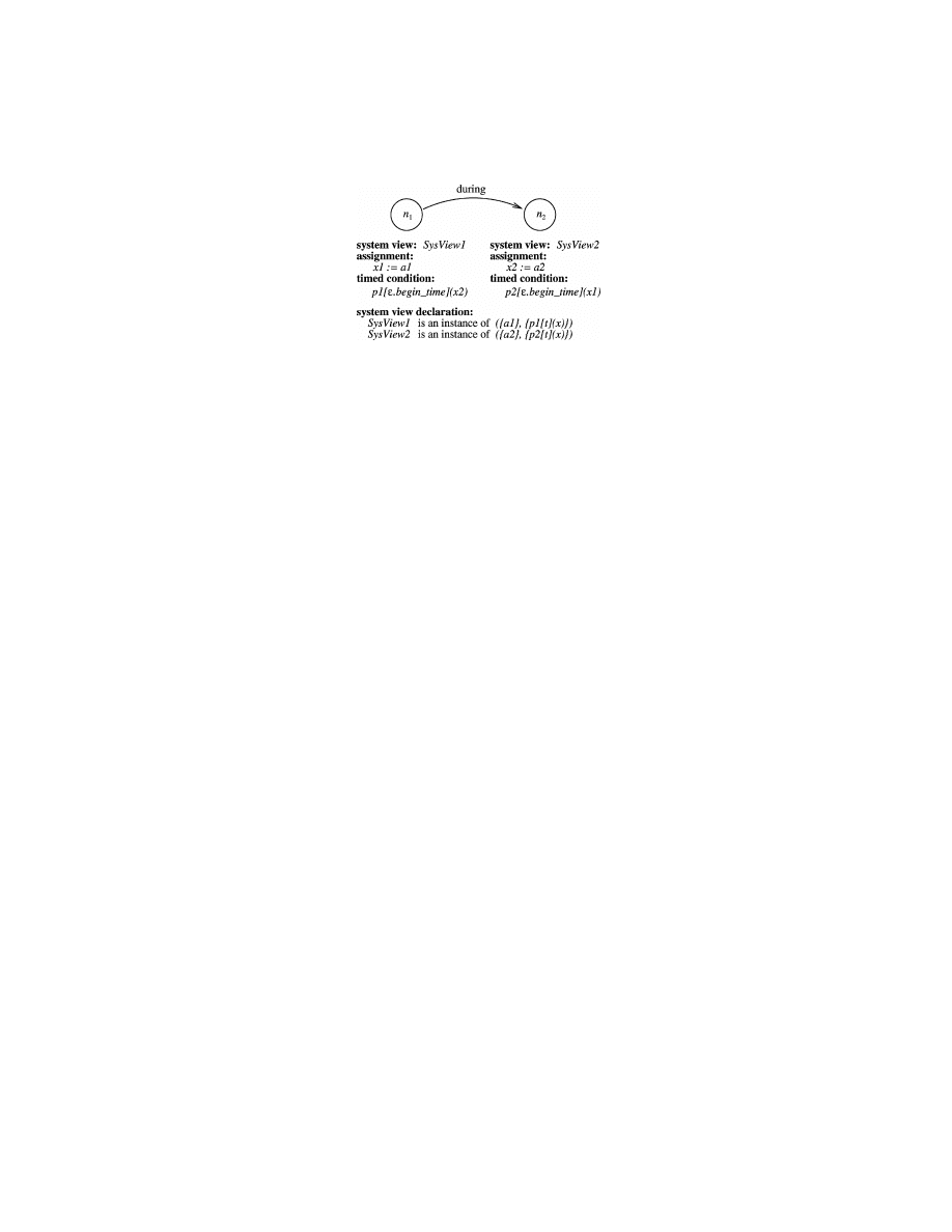
430
•
P. Ning et al.
Fig. 8. A nonserializable signature.
are defined on the abstract representations of underlying systems (i.e., system
views), and this abstraction usually leads to generic signatures that can ac-
commodate variants of the original attack. However, when the attack is to be
detected, the signature has to be mapped to specific systems, so that the IDS
can reason about the events observed on the specific system according to the
signature.
To distinguish the aforementioned two situations, we call a signature a spe-
cific signature if each system view instance used by the signature is associated
with a system that provides information (i.e., event history) for the correspond-
ing system view. In contrast, we call a signature a generic signature if there is
at least one system view instance not associated with any system. For example,
the signature shown in Figure 3 is generic, since no system view instance is
associated with any system. If we associate the three system view instances to
a network monitor M and two hosts A and B, respectively, it becomes a spe-
cific signature representing the Mitnick attack on these systems. Note that in
this article we consider whether a signature is generic or specific as a system
feature, and do not include it in the formal model.
One generic signature usually corresponds to more than one specific signa-
ture, since the attacks modeled by the generic signature may happen against
different targets. It is desirable to model attacks as generic signatures. When
the attacks are to be detected for particular target systems, the specific signa-
tures can be generated from the generic ones by associating the system view
instances with appropriate systems. However, this does not mean that we can
only write generic signatures. We can also write a specific signature for a par-
ticular system according to the configuration of the system.
5.2 Serializable Signatures
Not all signatures can be detected efficiently in a distributed way. Before pre-
senting our approach for distributed misuse detection, we first demonstrate a
“problematic” signature and then identify the signatures for which we have
efficient algorithms.
Consider the signature shown in Figure 8. Assume that the systems under-
lying the system view instances SysView 1 and SysView 2 are host 1 and host 2,
respectively. Note that the timed condition associated with n
1
needs the vari-
able x2 assigned at node n
2
, while the timed condition with n
2
requires the
variable x1 assigned at n
1
. Suppose both host 1 and host 2 want to process their
ACM Transactions on Information and System Security, Vol. 4, No. 4, November 2001.

Abstraction-Based Intrusion Detection
•
431
events locally. Whenever an event e
1
occurs, host 1 needs to send corresponding
information (at least the value of x1) to host 2, since the value of x1 is needed
to evaluate the events represented by n
2
. Similarly, all the events that occur
on host 2 need to be sent to host 1. In this example, each event requires a mes-
sage. When there are more nodes that need information from each other, more
messages will be required. For such signatures, a distributed approach entails
more message transmissions; a centralized approach that collects and analyzes
distributed events in a single place would be more appropriate.
The nature of this problem is the relationship between different nodes
(events) in a signature. We clarify this relationship as follows. We say that
a node n requires a variable x if x appears in the timed condition associated
with n. For any two nodes n and n
0
in a signature, we say n directly requires
n
0
if n requires some variables assigned at n
0
. Moreover, we say n requires n
0
if n directly requires n
0
or there exists another node n
00
such that n requires
n
00
and n
00
directly requires n
0
. For example, in Figure 8, n
1
requires n
2
and n
2
requires n
1
, since n
1
requires the variable x2 assigned at n
2
and n
2
requires
the variable x1 assigned at n
1
. As another example, in Figure 3, n
2
requires
n
1
, and n
3
requires both n
2
and n
1
. Intuitively, node n needs information from
node n
0
through variable assignments if n (directly) requires n
0
.
We now identify the signatures that can avoid the above situations by the
notion of serializable signature.
Definition 9.
A signature S is serializable if (1) the binary relation require
on the set of nodes in S is irreflexive, and (2) no positive node requires any
negative node.
The signature in Figure 3 is an example of serializable signatures: the rela-
tion require on the set of nodes
{n
1
, n
2
, n
3
} is irreflexive, and the only negative
node n
3
is not required by any node. However, the signature in Figure 8 is not
serializable, since n
1
and n
2
require each other.
Since the relation require is transitive by definition, it is implied that the
relation require on the set of nodes of a serializable signature is a strict partial
order.
Some nonserializable signatures can be transformed into equivalent seri-
alizable ones. Consider a variant of the signature in Figure 3 in which the
comparison SrcIP
= var IP is not placed in the timed condition associated with
node n
2
, but represented equivalently as var SrcIP
= VictimIP and placed in
the timed condition associated with n
1
. Then this signature is not serializable,
since node n
1
and n
2
require each other. However, we can always transform it
back into the equivalent form shown in Figure 3. Indeed, for any two nodes
that require each other in a nonserializable signature, if one of the problematic
variables appears in a conjunctive term of the timed condition that does not in-
volve a dynamic predicate, we can always place it into another timed condition,
as we did above, so that the two nodes no longer require each other.
In the rest of this article, we only consider the detection of attacks specified
by serializable signatures.
ACM Transactions on Information and System Security, Vol. 4, No. 4, November 2001.

432
•
P. Ning et al.
5.3 Detection Task and Workflow Tree
A signature for a distributed attack is composed of events distributed over mul-
tiple systems. When detecting such attacks, communication among different
systems is inevitable, since evidence from different places needs to be corre-
lated in some way in order to reason about the attacks. To avoid transmitting
all the distributed events to a centralized place for analysis, we let each system
process the events that it observes and all the systems that are involved in a
signature collaborate to perform the detection.
We consider the nodes in a signature as the basic processing units. An alter-
native is to treat all or some of the nodes in one system as one unit; however,
we will have to process the events for different nodes in one unit differently,
and thus obtain a similar result. For the sake of description, we informally call
the processing for a node n a detection task for n. (We will clarify the seman-
tics of the detection task later with a formal definition). Intuitively, a detection
task for node n determines whether an event corresponding to n satisfies the
conditions related to n.
The detection tasks in a signature are not isolated due to the relationships
between the nodes. In particular, the detection task for node n needs the infor-
mation from the detection task for node n
0
if n requires n
0
. For example, consider
the signature shown in Figure 3. Given only the events on SysView2, the de-
tection task for node n
2
will not be able to determine whether such an event
satisfies the condition for n
2
without the variable var IP assigned at node n
1
.
Therefore, we need to coordinate the detection tasks in a signature in order to
successfully perform intrusion detection.
Several issues are worth considering. First, the relation require on the set of
nodes in the signature should be reflected in the coordination. As we discussed
earlier, the relation require imposes the condition that the detection task for
node n
0
should give information to the detection task for n if n requires n
0
.
Second, positive events represent possible attacks; to ensure the security of the
system, positive events should be processed as soon as possible. Third, since the
goal is to determine whether a set of events constitutes an attack, the results
of all the detection tasks should finally be correlated together.
We use workflow trees to represent the coordination of the detection tasks in a
signature. The nodes in a workflow tree consist of all the nodes in the signature,
and an edge from one node to the other indicates that the detection task for the
latter node should send information (variable values and timestamps) to the
task for the former one. The workflow tree is formally defined as follows.
Definition 10.
A workflow tree for a serializable signature Sig is a tree
whose nodes are all the nodes in Sig and whose edges satisfy the following
conditions: (1) given two nodes n
1
and n
2
in Sig, n
2
is a descendant of n
1
if n
1
requires n
2
; and (2) there exists a subtree that contains all and only the positive
nodes in Sig.
Condition 1 says that the detection task for node n
1
(directly or indirectly)
receives information from the detection task for node n
2
if n
1
requires n
2
; condi-
tion 2 says that the detection tasks for positive events must be performed before
ACM Transactions on Information and System Security, Vol. 4, No. 4, November 2001.
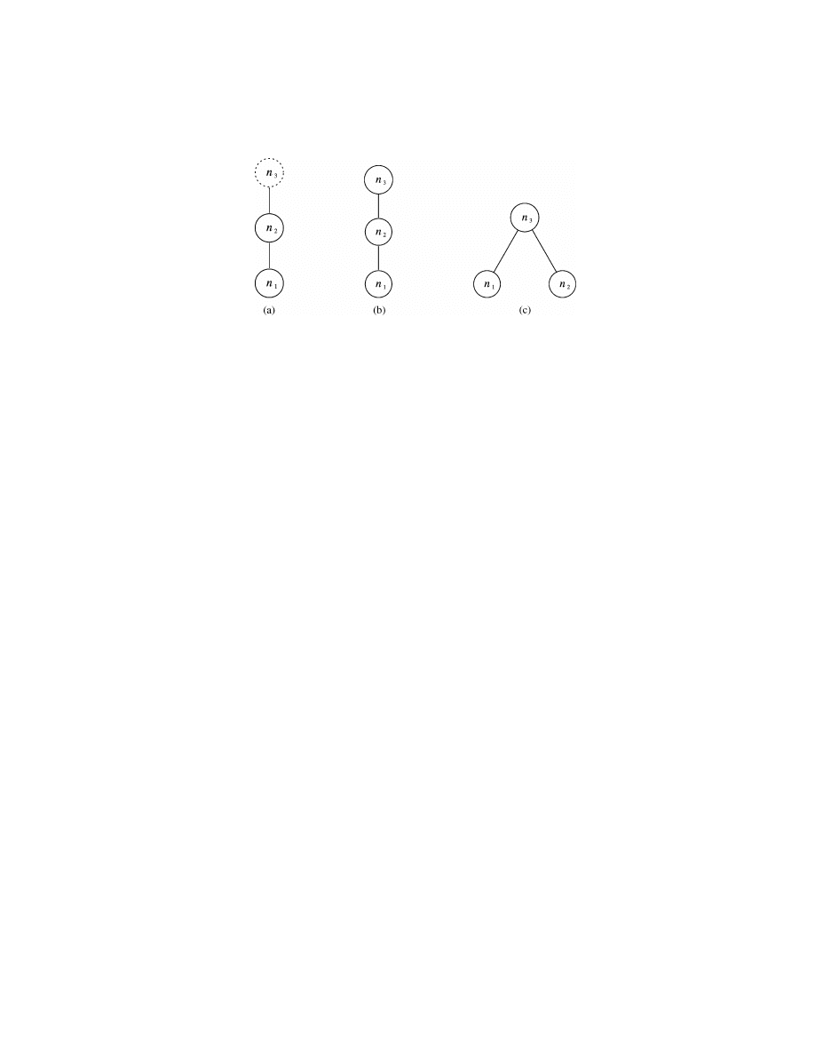
Abstraction-Based Intrusion Detection
•
433
Fig. 9. Examples of workflow trees.
the detection task for any negative event. Moreover, the tree structure ensures
that all the results of the detection tasks will finally be correlated together.
Figure 9(a) shows a workflow tree for the signature in Figure 3.
In a workflow tree, the root of the subtree that contains all and only the
detection tasks for the positive nodes is called the positive root, and the root of
the entire tree, if a negative node is called the negative root. For example, in
Figure 9(a), node n
2
is the positive root while node n
3
is the negative root.
Note that a workflow tree specifies the coordination of the detection tasks
in an attack; it does not specify the order of events. One node being a child of
another does not imply that the former node must happen before the latter one.
Another issue is the arrangement of negative nodes in workflow trees. In our
current approach, all positive nodes are arranged in a subtree, and no negative
node can appear under positive nodes. We may think that having negative
nodes between or under positive nodes can improve the performance. It is worth
pointing out that negative events are possibly observable events, not filtering
conditions. It is true that if we already observed some negative events, we may
be able to invalidate some positive events without going through all positive
nodes. However, such an arrangement also introduces difficult situations if we
do not observe the corresponding negative events. In this case, we have to send
the corresponding positive information to the rest of the positive nodes, and
two situations may result. On the one hand, if we do not later discover the
rest of the positive events, then sending positive information through negative
detection tasks already costs more. On the other hand, if we do find all positive
events involved in a possible attack, we still need to check with the previously
visited negative events, since some negative events may be observed after the
previous check. Thus, the aforementioned approach does not always result in
better performance than workflow trees. Further considering the simplicity of
workflow trees, we choose our current approach to coordinate the detection
tasks.
There are other alternative ways to represent the coordination of detection
tasks. For example, we may represent the coordination of detection tasks in
one signature as a directed acyclic graph with one sink, where the nodes are
the detection tasks, and an edge from one detection task to another represents
that the former detection task should send information to the latter one. An
ACM Transactions on Information and System Security, Vol. 4, No. 4, November 2001.

434
•
P. Ning et al.
important distinction between this alternative representation and the work-
flow tree is that, in the former representation, each detection task may send
messages to multiple detection tasks, while in the workflow tree, each detec-
tion task sends information to at most one detection task, and the information
required by more than one detection task is first sent to one task and then for-
warded to the others. Since most of the events in normal situations are normal,
most of the information sent by a detection task is expected and is not related
to an attack. Using the workflow tree will not only simplify the model, but also
reduce the number of messages when most of the messages are determined use-
less and not forwarded to other detection tasks. In some special cases, where
we would like to use signatures to, for example, assess the severity of an alert,
all information sent by a detection task may contribute to the final assessment;
however, we believe such signatures will not be the majority of the signatures
we will use.
One signature may have multiple workflow trees. Consider a signature that
has three positive nodes n
1
, n
2
, and n
3
, where n
3
requires both n
1
and n
2
.
Figures 9(b) and 9(c) show two different workflow trees for this signature. We
will discuss how to select appropriate workflow trees in the next section.
In the rest of this section, we first clarify what the detection tasks for a
signature with a given workflow tree are, and then describe how the detection
tasks are executed.
Definition 11.
Given a serializable signature Sig
= (N, E, SysView, Label,
Assignment, TimedCondition, PositiveNodes) and a workflow tree T for Sig, the
detection task for each n in N is an 11-tuple (n, sysview, assign, cond, p, PM,
C, CPM, type, isRoot, negativeRoot), where
– sysview
= SysView(n);
– assign
= Assignment(n) ∪{begin time
n
:
= begin time, end time
n
:
= end time};
– cond is the conjunction of TimedCondition(n) and the qualitative temporal
relationships (represented by E and Label) between n and n’s descendants
in T;
– p is the parent node of n in T if n is not the root, or p is the positive root if n
is the negative root;
– PM
= {begin time
n
0
, end time
n
0
| n
0
= n or n’s descendants} ∪ {the variables
assigned at n and n’s descendants and required by n’s ancestors
};
– C is the set of child nodes of n in T if n is not a leaf, and C contains the negative
root node if n is the positive root node but not the root of the whole workflow
tree;
– CPM is a mapping from C to sets of variables such that for each c
∈ C, CPM(c)
is the PM component of the detection task for c;
– type
= positive if n ∈ PositiveNodes, and type = negative otherwise;
– isRoot
= True if n is the root of T or the subtree of T that consists of all the
nodes in PositiveNodes, and isRoot
= False otherwise; and
– if n is the positive root and T has negative nodes, negativeRoot is the root of
T; otherwise, negativeRoot is NULL (invalid).
ACM Transactions on Information and System Security, Vol. 4, No. 4, November 2001.

Abstraction-Based Intrusion Detection
•
435
The formal definition of a detection task specifies the information required
for the processing of each event in a signature, as well as how this information
is derived from the signature and the corresponding workflow tree. The com-
ponent n identifies the event in the original signature; the component sysview
indicates the system view instance from which the detection task gets event and
state information about the monitored system; the component cond specifies the
condition that should be tested against each event on sysview; the component
assign includes all the assignments of event attributes to variables that should
be performed if an event on sysview satisfies cond; the component p identi-
fies the detection task (i.e., the parent detection task) to which this detection
task should send detection-related messages; the component PM specifies the
schema of the messages to be sent to the parent detection task; the component C
identifies all the detection tasks (i.e., the child detection tasks) from which this
detection task is going to receive detection-related messages; similar to PM, the
component CPM specifies the schema of the messages to be received from each
child detection task; the component type indicates whether this detection task
corresponds to a positive or a negative event; finally, the component isRoot tells
if this detection task corresponds to the root of the workflow tree or the subtree
consisting of all the positive nodes.
Note that timestamp information can be implicitly represented in signatures,
while in detection tasks, we explicitly represent the processing of timestamp
information by timestamp variables (e.g., begin time
n
and end time
n
). This is
because signatures are provided by human users; thus, using qualitative tem-
poral relationships can usually make this job easier. However, detection tasks
are developed for programs; hence, representing the timestamp information
explicitly is required.
Let us see an example before we discuss the execution of detection tasks.
Example 7.
Consider the signature for the Mitnick attack in Figure 3. The
detection task for n
1
is DT
1
= (n
1
, SysView1, assign
1
, cond
1
, n
2
, PM
1
,
∅, NULL,
positive, False, NULL), where
– assign
1
= {var IP := VictimIP, var Port := VictimPort, begin time
n
1
:
=
begin time, end time
n
1
:
= end time};
– cond
1
is True, and
– PM
1
= {begin time
n
1
, end time
n
1
, var IP, var Port
}.
This detection task says that it takes events on SysView1, which is an instance
of TCPDOSAttacks, and for each event that satisfies cond
1
, it makes the as-
signments in assign
1
and sends the assigned values to the detection task for n
2
as a tuple on PM
1
.
The detection task for n
2
is DT
2
= (n
2
, SysView2, assign
2
, cond
2
, n
3
, PM
2
,
C
2
, CPM
2
, positive, True, n
3
), where
– assign
2
= {var SrcIP := SrcIP, var SrcPort := SrcPort, var DstIP := DstIP,
var DstPort :
= DstPort, begin time
n
2
:
= begin time, end time
n
2
:
= end time};
– cond
2
is ((begin time
> begin time
n
1
) and (SrcIP
= var IP) and (SrcPort =
var Port) and LocalIP[
ε.begin time](DstIP) and Trust[ε.begin time](var IP));
ACM Transactions on Information and System Security, Vol. 4, No. 4, November 2001.

436
•
P. Ning et al.
– PM
2
= {var SrcIP, var SrcPort, var DstIP, var DstPort, begin time
n
1
,
end time
n
1
, begin time
n
2
, end time
n
2
};
– C
= {n
1
, n
3
}, and
– CPM
2
(n
1
)
= PM
1
, CPM
2
(n
3
)
= PM
3
.
This detection task says that it takes events on SysView2, which is an instance
of LocalTCPConn, and receives tuples on PM
1
and PM
3
from the detection
tasks for n
1
and n
3
, respectively. For each event and the variables that satisfy
cond
2
, it makes the assignments in assign
2
and sends the assigned values to
the detection task for n
3
as a tuple on PM
2
. Note that n
2
is the positive root in
the workflow tree. As we will see later, it processes the information from the
detection task for the negative root n
3
in a different way.
The detection task for n
3
is DT
3
= (n
3
, SysView3, assign
3
, cond
3
, n
2
, PM
3
,
C
3
, CPM
3
, negative, True, NULL), where
– assign
3
= {begin time
n
3
:
= begin time, end time
n
3
:
= end time};
– cond
3
is ((begin time
= begin time
n
2
) and (end time
= end time
n
2
) and (SrcIP
= var SrcIP) and (SrcPort = var SrcPort) and (DstIP = var DstIP) and (Dst-
Port
= var DstPort));
– PM
3
= {begin time
n
1
, end time
n
1
, begin time
n
2
, end time
n
2
, begin time
n
3
,
end time
n
3
};
– C
= {n
2
}; and
– CPM
3
(n
2
)
= PM
2
.
This detection task says that it takes events on SysView3, which is also an
instance of LocalTCPConn, and receives tuples on PM
2
from its child-detection
task identified by n
2
. For each event and the assigned variable values that
satisfy cond
3
, it makes the assignments in assign
3
and sends the assigned
values to the detection task for n
2
as a tuple on PM
3
(since n
2
is the positive
root in the workflow tree). Here we assume that each event from a particular
system is uniquely identified by its timestamp. Note that node n
3
represents
a negative event, and a satisfaction of cond
3
means that counter evidence is
found for a previously discovered match of the signature. Thus, the detection
task DT
2
can use the transmitted variable values to mark the match as a false
alarm.
5.4 Execution of Detection Tasks
The workflow tree provides a framework for coordinating detection tasks. In
this section, we further explain how each detection task is performed in this
framework. We assume that the processing of each event is atomic to ensure
correctness. Allowing concurrent processing of multiple events is interesting
and may improve the performance; however, we do not cover it in this article
but consider it as possible future work.
Figure 10 shows the algorithm for executing a detection task. In order to
have a concise description of the algorithm, we adopted some notation from
relational algebra. (Please refer to any database textbook (e.g., Ullman and
Widom [1997]) for the semantics of the notation).
ACM Transactions on Information and System Security, Vol. 4, No. 4, November 2001.
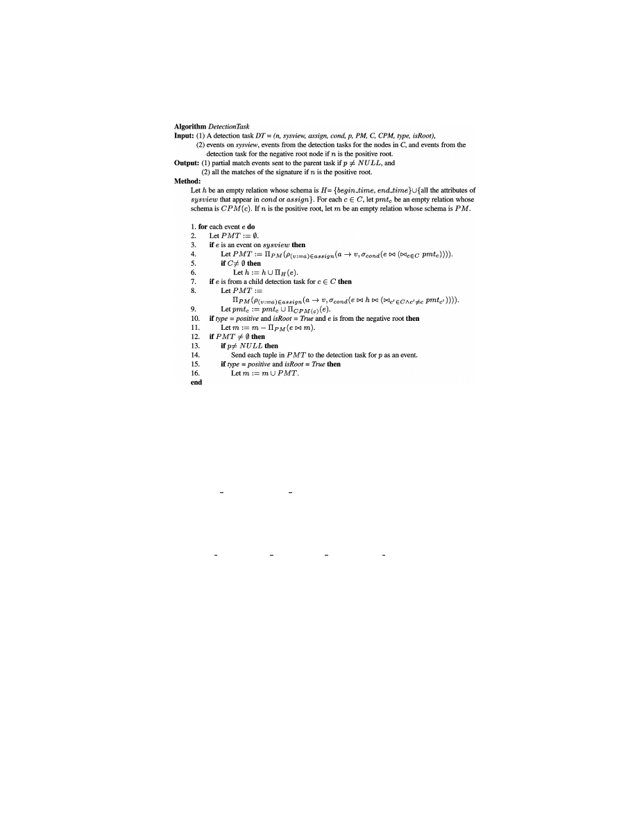
Abstraction-Based Intrusion Detection
•
437
Fig. 10. The algorithm for executing a detection task.
The algorithm uses several relations (tables) to keep events and detec-
tion results. The relation h, which we call the history table, keeps the nec-
essary information of the events on the system view instance, sysview. The at-
tributes of the history table consist of the timestamps and the event attributes
that appear in assign or the condition cond. For example, the detection task
DT
1
in Example 7 has the history table whose attributes consist of VictimIP,
VictimPort, begin time, and end time.
For each child node c
∈ C of n, the relation pmt
c
, which we call the partial
match table for c, keeps the variable values assigned by the child detection task
for c. The attributes of pmt
c
include all the variables in CPM(c). For example,
for the detection task DT
2
in Example 7, the partial match table pmt
n
1
has
attributes begin time
n
1
, end time
n
1
, var IP, and var Port.
If n is the positive root node in the corresponding workflow tree, the detection
task keeps a relation m (called the matched table) for the detection result of
the signature. In Figure 10, the attributes of the matched table include all the
variables in PM. Alternatively, we can use all the timestamp variables in PM
to identify the matches, assuming that each event is uniquely identified by its
timestamp.
Note that it is necessary for a detection task to keep both the event informa-
tion and the variable values received from its child tasks. The detection task
may be able to determine that a previously examined event is involved in an
attack after receiving additional information from its child tasks. Similarly,
the detection task needs to examine the information previously received from
the child tasks when a local event occurs. Thus, each detection task needs to
ACM Transactions on Information and System Security, Vol. 4, No. 4, November 2001.

438
•
P. Ning et al.
maintain both a history table and a partial match table for each child detection
task. As an exception, the detection tasks without child tasks do not need to
maintain any table.
The execution of the algorithm DetectionTask is presented in an event-driven
fashion. For the sake of presentation, we also consider the variable values
sent by a child detection task as an event whose attributes are the variable
names. To distinguish between different events, we call the events on system
view instances raw events and the events sent by a child detection task partial
match events.
When the detection task receives a raw event e on the system view sysview
(line 3), it first checks whether e satisfies cond along with some tuples in the
partial match tables pmt
c
. This is specified by a join of e with the partial match
tables pmt
c
for all c in C (line 4). The schema of the resulting relation is then
changed to PM by a series of renaming operations, followed by a projection
(line 4). Then selected attribute values of e are saved in the history table h if
necessary (lines 5 and 6).
When the detection task receives a partial match event e from a child task c
(line 7), it first checks whether this event satisfies cond along with the historical
events in h and partial match tables for c
0
other than c. Similarly, this is specified
by a join of e with h and all pmt
c
0
for all c
0
in C other than c (line 8). The schema of
the resulting relation is then changed to PM by a series of renaming operations
followed by a projection (line 8). Then selected attribute values of e are saved
in the partial match table pmt
c
as a tuple on CPM(c) (line 9).
If the detection task generates new partial match events (i.e., PMT
6= ∅), it
will send all the events to its parent-detection task (denoted by p) if it has one
(lines 12 to 14).
As a special case, if the detection task is for a positive root and there are
negative nodes in the corresponding workflow tree, the discovery of partial
matches (i.e., PMT
6= ∅) implies possible attacks represented by the signature.
This seems to introduce a dilemma. On the one hand, we cannot conclude that
an attack really happened if there are negative events in the signature, since
we may later discover counter evidence that invalidates these attacks. On the
other hand, if there really were attacks, not responding immediately may cause
further damage to the systems.
However, from the perspective of system security, avoiding damage to the
system is more important than avoiding false alarms (at least in our judg-
ment). Thus, we design the algorithm to work as follows. When the detection
task for a positive root node discovers a nonempty PMT, it saves the result into
the matched table m (lines 15 and 16), assuming they all correspond to attacks.
When the detection task for the positive root receives an event e from the de-
tection task for the negative root (i.e., counter evidence of previously detected
matches), it then removes all matches that share the same attribute values as
e (lines 10 and 11).
Note that the detection task for a negative event works in exactly the same
way as for positive events, unless the node is the root of the workflow tree. In
the latter case, it sends the timestamps of the events involved in each partial
match to the detection task for the positive root.
ACM Transactions on Information and System Security, Vol. 4, No. 4, November 2001.

Abstraction-Based Intrusion Detection
•
439
The execution of a detection task can be quite complex if the detection task
has many child tasks. The dominant steps are steps 4 and 8: Step 4 involves
a conditional join of the most recently discovered event and the partial match
tables; step 8 involves a conditional join of the most recently received partial
match event, the history table, and the other partial match tables. A naive
implementation of the join operation consists of testing the condition on all
combinations of the new event and the tuples in the other tables. Thus, step 4
would involve
5
c
∈C
|pmt
c
| tests of the condition, and similarly, step 8 would
involve
|h| × 5
c
0
∈C∧c
0
6=c
|pmt
c
| condition tests. Such a method corresponds to ex-
haustive search, and should be avoided in an implementation.
Two approaches can be used to reduce the execution cost. First, in-memory
database query optimization techniques such as in-memory hybrid hash join
[DeWitt et al. 1984] and T-Tree [TimesTen 2001] can greatly reduce the
cost of the join operation. Indeed, an in-memory database such as TimesTen
[2001] can be used in a component IDS to reduce the development cost. Sec-
ond, some join operations may be materialized to speed-up event process-
ing. For example, we can precompute
1
c
∈C
pmt
c
so that when a raw event
is discovered, it can be directly joined with the precomputed table. More re-
search is needed to make the execution of a single detection task efficient;
however, we do not address this problem in this article, but consider it as
future work.
Assume that the communication between detection tasks is resilient (i.e.,
a message inserted into the communication channel will be delivered to the
recipient eventually) and the clocks of different IDSs are well synchronized.
The correctness of the decomposition and algorithm DetectionTask is assured
by the following theorem.
T
HEOREM
1.
If all the detection tasks for a signature execute according to the
algorithm DetectionTask, then they will detect all and only the matches of the
signature.
Three issues are worth further clarification regarding Theorem 1. First,
Theorem 1 ensures the detection of the matches of the signatures, not the at-
tacks themselves. In other words, Theorem 1 says that under the aforemen-
tioned assumptions, we can detect the attacks as long as the evidence of the
attacks is present in the event histories. Second, this theorem does not imply
that each alarm raised by the system represents an attack, since an alarm may
later be disabled due to the discovery of negative events. Instead, it says that
each alarm represents an attack if it stays long enough. The exact threshold
to decide whether an alarm is a true positive depends on the network delays
and the processing time of the related detection tasks. More work is required
to decide the exact threshold, and its value may vary in different installations.
Third, there is a hidden assumption in the theorem: infinite memory. That is,
we never discard any information from the history tables or the partial match
tables. However, in reality, we may have to discard some data from these tables
due to limits in memory. As a result, we may miss some stealthy attacks or have
false alarms.
ACM Transactions on Information and System Security, Vol. 4, No. 4, November 2001.

440
•
P. Ning et al.
5.5 Optimization
As we pointed out earlier, one signature may have several workflow trees. De-
tecting the same signature with different workflow trees may result in different
performances, since they may have different storage requirements and differ-
ent patterns of message transmission between detection tasks. We discuss how
to select a good workflow tree in the next section.
Even with a fixed workflow tree, optimization is still available to improve
performance. A detection task can sometimes determine that an event on the
system view is not involved in an attack, even if it needs information from
other detection tasks. For example, in the workflow tree in Figure 9(a), which
is a workflow tree for the signature in Figure 3, the detection task for n
2
can decide that a TCP connection event e is not involved in any attack if
the destination IP address does not belong to the host being monitored (i.e.,
LocalIP[e
.begin time](DstIP) = False). In general, we can transform the cond
component of a detection task into the conjunction of two conditions such that
one of them involves only the event attributes and constants. We call this part
of the cond component a sieving condition. In the above example, the sieving
condition is LocalIP[e
.begin time](DstIP). The sieving conditions can be evalu-
ated without any information from other detection tasks, and only the events
that satisfy the sieving condition need further consideration. Moreover, if we
can measure the likelihood that each conjunctive term of cond is false, we can
check those that have higher likelihood of being false and thus avoid unneces-
sary evaluations.
Another observation reveals further opportunities for optimization. This
can be explained with the above example as well. In order for an event e
on the system view instance SysView2 to be a part of an attack, it must
satisfy SrcIP
= var IP, which is implied by the condition cond
2
. This means
that we can replace the variable var IP with the attribute SrcIP in the pred-
icate Trust[
ε.begin time](var IP), and still have an equivalent condition. As
a result, the sieving condition of the detection task n
2
can be expanded to
(Trust[
ε.begin time](Src IP) and LocalIP[ε.begin time](DstIP)) and filter out
more events than the original one. In general, we can perform an equality
analysis through the assignments and the timed conditions in the signature to
find out all variables and attributes that are equivalent to each other. Then, in
the condition component cond of each detection task, if a variable is equivalent
to an attribute of the system view instance, we can replace the variable with
the attribute.
The reader may have noticed that when the size of the history and the partial
match tables grow very large, the performance of the algorithm DetectionTask
may be greatly affected due to the join operations (lines 4 and 7 in Figure 10).
Moreover, the detection task may not be able to grow these tables when mem-
ory is limited. A practical solution, which has been used many times in similar
contexts (e.g., the token replacement policy in Kumar [1995]), is to periodically
remove out-of-date tuples from the history and the partial match tables (using
a replacement policy). This can certainly improve performance; however, in the-
ory, the revised algorithm may miss some stealthy attacks, since some evidence
ACM Transactions on Information and System Security, Vol. 4, No. 4, November 2001.

Abstraction-Based Intrusion Detection
•
441
could be removed before being correlated with others. More severely, an at-
tacker may intentionally create a large number of partial matches to launch
a denial of service attack against the IDS. To detect such attempts, a statistic
(e.g., the size of the table) may have to be associated with each history/partial
match table. Nevertheless, this is a problem common to all IDSs that need to
keep state about partial detection results (e.g., USTAT [Ilgun et al. 1995]).
The algorithm DetectionTask requires that each detection task maintain a
history table for the raw events that are possibly involved in attacks. However,
one event may be stored in more than one history table if several detection
tasks take raw events from the same system view instance. An alternative
way to avoid this situation is to maintain one history table for each system
view instance. However, this approach is not a silver bullet either. When a
detection task receives partial match events from its child tasks, it will have to
determine whether a candidate event stored in the history table satisfies the
condition together with the newly received information, which means that it
will have to scan the records in the history table. Maintaining one history table
for each system view instance will inevitably increase the size of the history
table, and thus increase scanning time. A trade-off between time and space may
be desirable, but is not in scope of this article.
6. GENERATING A WORKFLOW TREE
As we discussed in Section 5, different workflow trees for a given signature may
result in different performances. Three major factors that reflect performance
are CPU time, message transmission, and the storage requirement. The less
requirement for the three factors, the better performance of the workflow tree.
Theoretically, we can define the optimal workflow tree for a specific signa-
ture as the one with the least CPU usage, message transmission, and space
requirement, and use the optimal workflow tree to gain the best performance.
However, this requires a measurement of the CPU usage, the message trans-
mission, and the space requirement by the specific signatures, which involves
not only how message are transmitted but also how often each type of event in
the specific signature occurs and how conditions are evaluated.
An interesting approach to achieve this is to develop a cost model that can
estimate the aforementioned measurements and select the optimal workflow
tree according to the model. However, the development of the cost model will
inevitably involve calculating (or estimating) the frequency of various types of
events, which is usually time-consuming, and the resulting model will depend
on the systems that are used to generate the cost model and may change as
time goes on.
In the following, we present an alternative approach that considers several
heuristics that usually lead to “good” workflow trees.
6.1 A Heuristic Approach
In this section we discuss three principles for developing effective workflow
trees as well as their relationships, and then present the heuristic algorithm
that generates workflow trees on the basis of the principles.
ACM Transactions on Information and System Security, Vol. 4, No. 4, November 2001.

442
•
P. Ning et al.
The edges in a workflow tree represent the required information flows in the
detection process. An edge implies message transmission between two systems
if the detection tasks for the two nodes involved in the edge are located at
different systems. If one node requires another node, a path between them is
certainly unavoidable. However, unnecessary edges may result in unnecessary
message transmissions and additional storage.
Consider a specific signature with three nodes n
1
, n
2
, and n
3
, where n
3
re-
quires both node n
1
and n
2
, and the system views associated with the three
nodes belong to three different systems. This signature has two workflow trees
shown in Figures 9(b) and 9(c). The workflow tree in Figure 9(b) is bad, since
the variable values assigned at n
1
must be sent to n
3
through n
2
, resulting
in two message transmissions and additional storage at n
2
. On the other hand,
the workflow tree in Figure 9(c) is better than the previous one, since it allows
the variable values assigned at n
1
and n
2
to be sent to n
3
separately. This exam-
ple suggests that a workflow tree should avoid unnecessary edges. Principle 1
states this observation.
P
RINCIPLE
1.
Place an edge from node n
1
to node n
2
only when (1) n
1
requires
n
2
, or (2) n
1
requires node n
0
and there is a path from n
2
to n
0
.
If the inclusion of the edges is unavoidable, the system views associated with
the two nodes involved in an edge should at least be located at the component
system, so that the necessary information flow will be processed in the same
local system instead of being transmitted between different systems. Principle 2
states this observation.
P
RINCIPLE
2.
If there has to be a path between two nodes that belong to the
same system, place an edge directly between them whenever possible.
Different events usually occur at different rates. We call the events that
happen infrequently the rare events. For example, the event represented by
node n
1
in Figure 3, which is a DOS attack, is a rare event, since such an event
seldom happens in a normal network. Note that rare events are relative and
context-dependent. A type of event that is rare in one situation may not be rare
in another.
Rare events can help improve workflow tree generation. Note that a partial
match event is generated at node n only if n has received partial match events
from n’s child nodes. Since rare events occur infrequently, the nodes that have
rare events as descendants tend to generate fewer partial match events than
the other nodes. Indeed, the lower the placement of the rare events in the
workflow tree, the fewer partial match events will occur, and the less message
transmission and storage are required. This leads to Principle 3.
P
RINCIPLE
3.
Place the nodes for rare events as close to the leaves as possible.
There may be conflicts between the principles. For example, the workflow
tree shown in Figure 9(c) is better than the one in Figure 9(b) according to
Principle 1. However, if event n
1
is extremely rare, it may be better to choose the
latter according to Principle 3. To precisely decide which one is better requires
ACM Transactions on Information and System Security, Vol. 4, No. 4, November 2001.
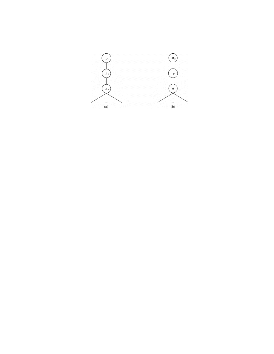
Abstraction-Based Intrusion Detection
•
443
Fig. 11. Comparison of two workflow trees.
the cost of both workflow trees, which is what we want to avoid, as discussed
earlier.
Here we compare the three principles in normal situations and order them
in terms of their priorities. First, let us compare Principles 1 and 3 using the
aforementioned example. Suppose n
1
is rare. At first glance, it seems that the
workflow tree in Figure 9(b) is much better than the one in Figure 9(c). One
reason could be that with the workflow tree in Figure 9(b), detection task n
2
does not need to send messages to n
3
if it has not received anything from n
1
.
Moreover, if the history table of n
2
is limited to a certain size, some information
may be dropped without being transmitted at all. However, this reasoning is
flawed if we look at another aspect of this workflow tree. Note that n
2
does not
require n
1
, which implies that the information sent by detection task n
1
will not
reduce the information stored in the history table of n
2
. As a result, if we use
the workflow tree in Figure 9(b), each event detected by detection task n
1
will
generate a partial match along with each tuple stored in the history table of n
2
.
The information sent to detection task n
3
is then the Cartesian product of the
history tables of n
1
and n
2
. In contrast, if the workflow tree in Figure 9(c) is used,
only the history tables need to be sent. Therefore, we assign Principle 1 higher
priority than Principle 3. (Note that in extreme cases, i.e., when n
1
is extremely
rare, the workflow tree in Figure 9(b) may have less cost). A similar reasoning
can show that we should give higher priority to Principle 1 than Principle 2.
Now let us compare Principles 2 and 3. Suppose r, n
1
, and n
2
are three
events (among others) involved in a signature. Assume that event r is rare,
and events n
2
and n
3
are in the same component system. Figure 11(a) shows
the workflow tree that we will select if Principle 2 is given higher priority, and
Figure 11(b) shows the workflow tree that we will choose if we favor Principle 3
over Principle 2. With the workflow tree in Figure 11(b), both n
1
and r need to
transmit messages through the network in order to send information to their
parent detection tasks. However, since event r is rare and it requires variables
from its descendants, r will have many fewer partial matches than n
1
, and the
messages from r to n
2
will be many fewer than those from n
1
to r. In contrast,
with the workflow tree in Figure 11(a), only the messages from n
2
to r need
to be sent in the network, since n
1
and n
2
are located in the same component
system. If we assume that sending messages from n
1
to r in the first case has
ACM Transactions on Information and System Security, Vol. 4, No. 4, November 2001.
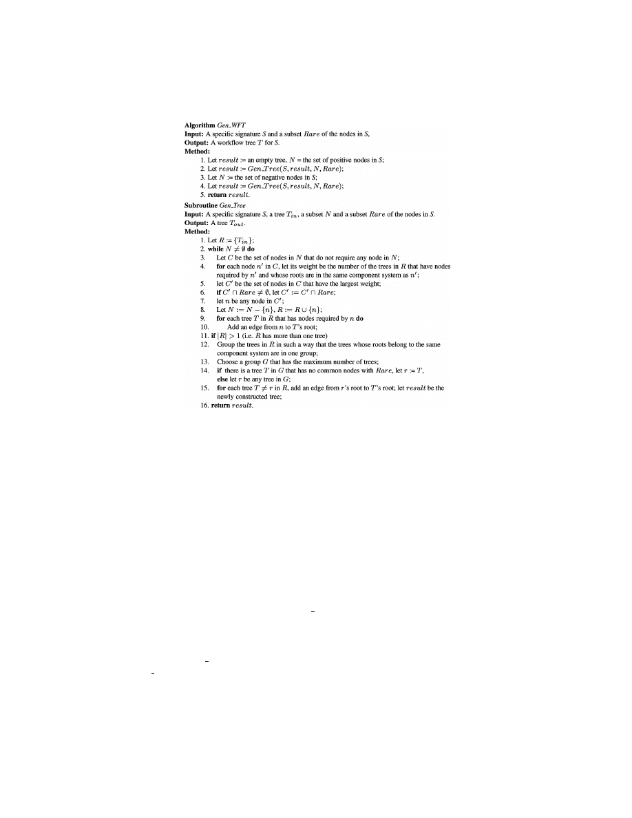
444
•
P. Ning et al.
Fig. 12. The algorithm to generate a workflow tree from a specific signature.
roughly the same cost as transmitting messages from n
2
to r in the second case,
then the workflow tree in Figure 11(b) has a little more cost than the one in
Figure 11(a) in terms of message transmission. However, when detecting an
attack, the workflow tree in Figure 11(b) involves two messages between the
component systems in which the three nodes are located, while the workflow
tree in Figure 11(a) has only one. Thus, the workflow tree in Figure 11(b) in-
troduces longer delay than the one in Figure 11(a). Nevertheless, the workflow
tree in Figure 11(b) requires less space than the one in Figure 11(a), since the
partial match table of r in Figure 11(b) will be smaller than that of n
2
in Fig-
ure 11(a) due to the rareness of r. Here we care more about detection speed
than the space requirement; thus, we decided to give Principle 2 a higher pri-
ority. Principle 3 may have higher priority than Principle 2 if space becomes a
compelling concern.
Figure 12 shows the algorithm Gen WFT developed according to these prin-
ciples. The input of the algorithm consists of a specific signature S and a set
Rare of the nodes corresponding to rare events, which is a subset of the nodes
in S. The output of the algorithm is a workflow tree for S. The algorithm uses a
subroutine Gen Tree to help construct the target workflow tree. The algorithm
Gen WFT first generates the part of the workflow tree for the positive nodes
and then the whole tree, ensuring that the processing of a positive event does
not require the processing of any negative one(s).
ACM Transactions on Information and System Security, Vol. 4, No. 4, November 2001.
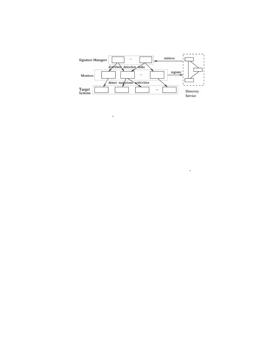
Abstraction-Based Intrusion Detection
•
445
Fig. 13. The CARDS architecture.
In the subroutine Gen Tree, the algorithm first constructs a set of trees ac-
cording to the relationship require, the location where the events are observed,
and the rare event information (steps 2–10). The algorithm always chooses a
node that does not require any node not in R as the next candidate to be pro-
cessed. Since the relation require is a strict partial order, the algorithm can
always find a candidate event.
As shown in steps 4–7, the algorithm tries to find the nodes that will arrange
the most number of nodes in one component system (Principle 2), and then tries
to find a rare event from them (Principle 3). In steps 9 and 10, the algorithm
adds edges only when necessary (Principle 1).
After processing all of the input nodes, the subroutine Gen Tree builds one
single tree if the previous steps result in more than one tree (steps 11–15).
The algorithm chooses one of them and adds edges from its root to the roots of
all the others. To minimize message transmission, the algorithm chooses the
tree whose root belongs to the component system having the most roots of the
aforementioned trees (Principle 2). Again, the algorithm places rare events as
close to the leaves as possible by trying not to choose a tree that has nodes
representing rare events (Principle 3).
7. CARDS: AN EXPERIMENTAL SYSTEM
A prototype system, named Coordinated Attack Response and Detection
Systems (CARDS), is being developed to explore the feasibility of the approaches
proposed in this article. The preliminary design and development of CARDS is
described in Yang et al. [2000]. CARDS is composed of three kinds of indepen-
dent but cooperative components: signature manager, monitor, and directory
service. Figure 13 shows the architecture of CARDS. In a typical environment,
there may be one or more signature managers and one or more monitors. The
monitors can be embedded in the monitored system or as a dedicated system
separate from the monitored system. Different monitors can cooperate with
each other through message passing when they are involved in cooperative
detection of attacks.
As shown in Figure 13, with the monitor configuration information (i.e., what
system view instances are provided by the monitors) retrieved from the direc-
tory service, a signature manager generates specific signatures from generic
signatures, decomposes specific signatures into detection tasks (according to
ACM Transactions on Information and System Security, Vol. 4, No. 4, November 2001.
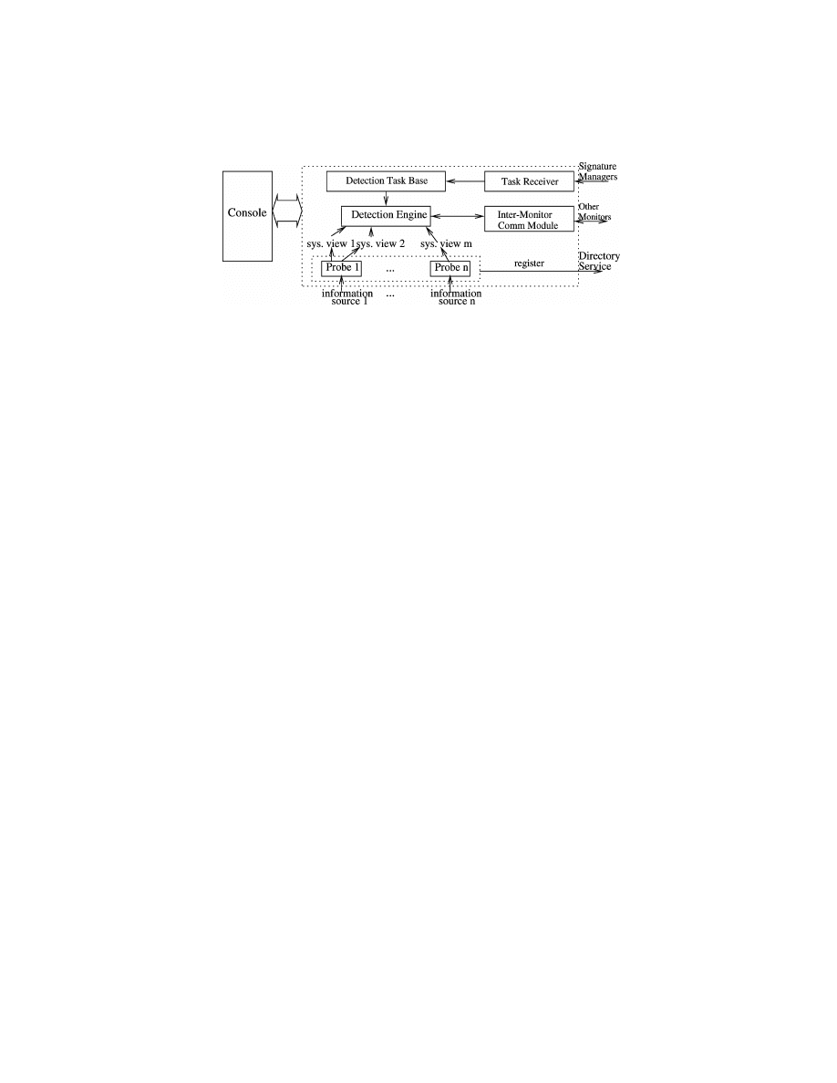
446
•
P. Ning et al.
Fig. 14. The monitor architecture.
the methods in Sections 5 and 6), and distributes these tasks to the monitors
involved.
Given a generic signature, the signature manager generates specific signa-
tures for all possible systems that can provide the system view instances re-
quired by the generic signature. This is because, in theory, the attack specified
by the generic signature may happen to all these systems; thus, all of them
should be protected against the attack. However, people may not want to detect
all specific signatures of a generic one, due to some administrative concerns.
We envisage some support for the generation of specific signatures according
to different administrative concerns. However, this is not in the scope of this
article. We do not cover it in this article nor in the current implementation of
CARDS.
Monitors are the components that carry out the detection tasks. At the begin-
ning of detection, each monitor receives detection tasks from signature man-
agers. During detection, it cooperates with other monitors if some detection
tasks are parts of some distributed attacks.
Figure 14 shows the inner structure of a monitor, which is composed of one
or more probes, a detection engine, an intermonitor communication module, a
detection task base, and a task receiver.
Probes are responsible for collecting information from the target system,
filtering and reformatting the information into structures defined by system
views, and providing the results to the detection engine. Each probe gets in-
formation from one particular source, such as a host audit trail. A probe could
also be used to derive information from a signature; however, this function-
ality has not yet been implemented in the current system. The system view
configuration of each probe (i.e., system view instances that each probe pro-
vides) should be registered in the directory service, which is later retrieved by
signature managers to generate specific signatures.
The task receiver receives commands for adding or removing detection tasks
from the signature manager, and then adds or removes detection tasks from or
to the detection task base accordingly.
The detection engine is the core module of the monitor that executes the
detection tasks. When a detection task is derived from a specific signature
involving several monitors, the detection engine cooperates with the detection
engines in the related monitors by passing messages through the intermonitor
communication module. The console is the monitor’s user interface.
ACM Transactions on Information and System Security, Vol. 4, No. 4, November 2001.

Abstraction-Based Intrusion Detection
•
447
The directory service is the information center for providing system-wide in-
formation to both signature managers and monitors. Two types of information
are provided: system view definition and system view configuration. The sys-
tems view definition specifies the structures and the semantics of the system
views. Once a system view is defined, its definition should be placed in the di-
rectory service. The system view configuration information specifies the system
view instances provided by the probes (of the monitors).
The directory service is critical for the scalability of IDS. It allows the sig-
nature managers and the monitors to work in a decentralized and scalable
manner and deal with only the components necessary for conducting the desig-
nated detection tasks. However, the unavailability of the directory service does
not affect the cooperation of detection tasks; instead, it only prevents signature
managers from generating specific signatures. Nevertheless, if possible, the di-
rectory service should be replicated and distributed (using, for example, LDAP
replication server) to provide better availability.
The current version of CARDS is mostly written in Java, with a few probes
written in C
++ and incorporated into the system via Java Native Interface
(JNI). CARDS uses XML to describe system views, signatures, and detection
tasks. However, to save processing time, events transmitted between detection
tasks are described using attribute name-value pairs. Since secure communi-
cation between the components is not the focus of this system, message trans-
mission between components is carried out over TCP.
We conducted experiments in small-scale systems. The results show the fea-
sibility of signature decomposition and the distribution and execution of de-
tection tasks. Further results in large distributed systems are needed to eval-
uate the scalability of the proposed approaches. In addition, our experience
shows that in a large distributed system, it is necessary to have some mecha-
nisms to support various policies regarding the generation of specific signatures
from generic ones. However, we do not cover the policy issue in this paper but
consider it as future work.
8. CONCLUSION AND FUTURE WORK
In this article, we explored the abstraction-based misuse detection in dis-
tributed environments. We extended the misuse-detection model in ARMD
[Lin et al. 1998], which was developed to address the portability of misuse sig-
natures for host-based IDSs, to provide a hierarchical model for distributed
attack specification and event abstraction. In addition, we developed a decen-
tralized approach to detect attacks distributed over multiple systems. We also
implemented an experimental system called CARDS Yang et al. [2000] to ex-
amine the feasibility of the proposed approach.
The support provided by our model enables event abstraction to be dynamic,
and also benefits the attack specification process. As a misuse-detection method,
our approach allows signatures to accommodate unknown variants of known
attacks. However, this does not imply that our approach can detect entirely new
attacks. The unknown attacks that can be detected must share the essential
features of some existing signature. In addition, the choice of system views and
ACM Transactions on Information and System Security, Vol. 4, No. 4, November 2001.

448
•
P. Ning et al.
specification of signatures still depend on the signature writers’ understanding
of the attacks. Thus, an experienced signature writer may have a good signature
that captures the nature of the attack, while a novice may have a narrowly
defined or even incorrect signature.
The simplicity of the revised model led to a decentralized approach for de-
tecting distributed attacks. Considering each event in a signature as a ba-
sic processing unit (i.e., detection task), this approach does not require that
all the information be sent to a central place. Instead, one component IDS
needs to send messages to another one only when necessary. This greatly
reduces the network bandwidth and processing time required to detect dis-
tributed attacks. In addition, taking rare events into consideration further
improves the detection performance. The same method may be applicable to
some anomaly-detection models if we can clearly identify the require rela-
tion in them. Nevertheless, this needs further work and is not in the scope of
this article.
In addition to the difficulty of writing good signatures, the approach in this
article has several other limitations. Our approach requires reasonably well
synchronized clocks in various component systems, continuous operation of
each participating component IDS, as well as the availability and authentic-
ity of the communication channels between them. If these requirements are
not satisfied, systems using our approach may produce false alarms and miss
certain attacks. Moreover, a trade-off has to be made about how much histori-
cal audit data to keep in each component IDS due to memory constraints and
performance reasons. On the one hand, if we decide to keep too much data, a
component IDS may not have enough memory to keep the historical data and
the performance of a component IDS may degrade. On the other hand, if we
do not keep enough historical data, we may miss some stealthy attacks. Nev-
ertheless, these problems are not unique to our approach, but common to all
distributed intrusion detection techniques.
The CARDS experimental system provides a test-bed for the abstraction-
based approach proposed in this article. In CARDS, specification of distributed
attacks is separated from the detection of the attacks. Distributed attacks are
described by generic signatures, which are common to all systems that provide
the system views underlying the signatures. To protect specific systems, generic
signatures are first mapped to specific signatures using the system configura-
tion information, and then specific signatures are decomposed into detection
tasks, which are distributed to and executed by the cooperative component
IDSs. Our experience with CARDS showed the feasibility of the abstraction-
based approach, and also pointed out more research issues that need to be
addressed.
Several issues are worth future research. In this article, we studied how to
generate and distribute detection tasks from signatures, and the whole process
was done in a predefined manner. An interesting way that could possibly im-
prove the performance is to dynamically and adaptively generate and distribute
detection tasks according to the current detection result. The second issue is
to further improve the performance of individual detection tasks. Our current
research on distributed detection focuses on the coordination of detection tasks;
ACM Transactions on Information and System Security, Vol. 4, No. 4, November 2001.

Abstraction-Based Intrusion Detection
•
449
however, it is equally important to execute detection tasks efficiently. The third
issue is the generation of specific signatures from generic ones. Here we gen-
erate all possible specific signatures from one generic one according to the
current system configuration. A policy language that can control the specific
signature generation process could provide more flexibility from the admin-
istration’s perspective. Finally, we will continue to refine the implementation
of CARDS.
APPENDIX
A. PROOF OF THEOREM 1
P
ROOF
.
Consider a set of detection tasks derived from a signature Sig
= (N,
E, SysView, Label, Assignment, TimedCondition, PositiveNodes) and a work-
flow tree T for Sig.
Suppose there is a match of Sig. This implies that for each positive node n in
Sig there is an event, denoted e
n
, on the system view associated with n such that
they together satisfy the three conditions specified in Definition 5. Consider the
detection task DT
l
for a leaf node n
l
in T. The cond component of DT
l
is the
timed condition associated with n
l
according to Definition 11. Since the event
e
n
l
satisfies the timed condition associated with n
l
(which equals cond) and
there is no child-detection task, the PMT table in step 4 of the algorithm will
contain the values of the variables required by other detection tasks. Since the
communication is resilient, the variable values in PMT are sent to the detection
task for the parent node of n
l
.
Now consider the detection task DT
i
for an interior node n
i
. Event e
n
i
is
saved in the history table h at step 6 of the algorithm DetectionTask. If DT
i
receives the variable values assigned from e
n
c
for all child nodes n
c
of n
i
, it will
compute a nonempty PMT table in either step 4 (when it receives e
n
i
after all
the variable values) or step 8 (other situations), since e
n
i
and e
n
c
’s are part of the
match. The table PMT contains the variable values assigned from e
n
i
(through
the renaming operation) or inherited from the detection tasks for n
i
’s child
nodes. Then, in step 14, DT
i
sends the variable values to its parent-detection
task. By induction, the detection task for the positive root node in T will store
the timestamps of e
n
’s. This is to say that all matches of the signature will be
detected by the algorithm DetectionTask.
For each tuple t in the matched table m, t has timestamp attributes
begin time
n
and end time
n
for each positive node n in Sig, which together
identify an event e
n
on the system associated with n. For each node n, since
begin time
n
and end time
n
are finally transmitted to the detection task for
the positive root, e
n
must satisfy the cond component of the corresponding
detection task. According to Definition 11, the cond component of each de-
tection task is the conjunction of the timed condition associated with n and
the qualitative temporal relationships between n and n’s descendants in T.
This has two implications: First, e
n
satisfies the timed condition associated
with n. Second, for each arc (n
1
, n
2
) in Sig, either n
1
(when n
1
is closer to
the root) or n
2
(when n
2
is closer to the root) satisfying the cond compo-
nent implies that e
n
1
and e
n
2
satisfy the qualitative temporal relationship
ACM Transactions on Information and System Security, Vol. 4, No. 4, November 2001.

450
•
P. Ning et al.
represented by the labeled arc. This means that there is a match for all the
positive nodes.
If N
6= PositiveNodes and there exists a match of all the nodes in Sig, the
detection task for the negative root in T will discover this match and send the
timestamp variables to the positive root. Then this match will be removed from
m in step 11. This is to say that all the tuples that remain in m long enough
(i.e., longer than the time required to process and transmit the negative events)
represent matches of the signature Sig. This concludes the proof.
ACKNOWLEDGMENTS
The authors are grateful to the anonymous reviewers for their valuable com-
ments. The authors also thank Ravi Sandhu and Eugene Spafford for their
suggestions on improving the quality of this article.
REFERENCES
A
LLEN
, J. F. 1983. Maintaining Knowledge about Temporal Intervals. Commun. ACM, 26, 11:
832–843, November 1983.
A
NDERSON
, J. P. 1980. Computer security threat monitoring and surveillance. Tech. Rep. Anderson
Co. Fort Washington, PA.
B
ACE
, R. G. 2000. Intrusion Detection. Macmillan Technology, 2000.
B
ARBAR
´
A
, D., W
U
, N.,
AND
J
AJODIA
, S. 2001. Detecting novel network intrusion using bayes estima-
tors. In Proceedings of the First SIAM Conference on Data Mining, April 2001.
B
ISHOP
, M. 1990. A security analysis of the NTP protocol version 2. In Proceedings of the 6th
Annual Computer Security Applications Conference, pp. 20–29.
C
HANG
, H., W
U
, S. F.,
AND
J
OU
, Y. F. 2001. Real-time protocol analysis for detecting link-state
routing protocol. ACM Trans. Inf. Syst. Secu, 4, 1, Feb. 2001.
C
HANG
, H. Y., N
ARAYAN
, R., S
ARGOR
, C., J
OU
, F., W
U
, S. F., V
ETTER
, B. M., G
ONG
, F., W
ANG
, X., B
ROWN
,
M.,
AND
Y
UILL
, J. J. 1999. DECIDUOUS: Decentralized source identification for network-based
intrusions. In Proceedings of the 6th IFIP/IEEE International Symposium on Integrated Network
Management. IEEE.
C
HANG
, H. Y., W
U
, S. F., S
ARGOR
, C.,
AND
W
U
, X. 2000. Towards tracing hidden attackers on un-
trusted IP networks. submitted for publication, 2000.
C
URRY
, D.
AND
D
EBAR
, H. 2001. Intrusion detection message exchange format data model and ex-
tensible markup language (xml) document type definition. Internet draft, draft-ietf-idwg-idmef-
xml-03.txt, Feb.
D
E
W
ITT
, D. J., K
ATZ
, R. H., O
LKEN
, F., S
HAPIRO
, L. D., S
TONEBRAKER
, M. R.,
AND
W
OOD
, D. 1984.
Implementation techniques for main memory database systems. SIGMOD Rec. 14, 2, 1–8.
F
EIERTAG
, R., K
AHN
, C., P
ORRAS
, P., S
CHNACKENBERG
, D., S
TANIFORD
-C
HEN
, S.,
AND
T
UNG
, B. 2000. A
common intrusion specification language. http://www.gidos.org/drafts/language.txt.
F
EIERTAG
, R., R
HO
, S., B
ENZINGER
, L., W
U
, S., R
EDMOND
, T., Z
HANG
, C., L
EVITT
, K., P
ETICOLAS
, D., H
ECKMAN
,
M., S
TANIFORD
, S.,
AND
M
C
A
LERNEY
, J. Intrusion detection inter-component adaptive negotiation.
Comput. Netw. 34, 605–621.
F
EINSTEIN
, B. S., M
ATTHEWS
, G. A.,
AND
W
HITE
, J. C. C. 2001. The intrusion detection exchange
protocol (IDXP). Internet Draft. draft-ietf-idwg-beep-idxp-02.txt. March.
F
REKSA
, C. 1992. Temporal reasoning based on semi-intervals. Artifi. Intell. 54, 199–227.
F
RINCKE
, D., T
OBIN
, D., M
C
C
ONNELL
, J., M
ARCONI
, J.,
AND
P
OLLA
, D. 1998. A framework for coop-
erative intrusion detection. In Proceedings of the 21st National Information Systems Security
Conference (Crystal City, VA, Oct).
H
EBERLEIN
, L. T., M
UKHERJEE
, B.,
AND
L
EVITT
, K. N. 1992. Internetwork security monitor: An
intrusion-detection system for large-scale networks. In Proceedings of 15th National Computer
Security Conference (Baltimore, MD, Oct.), 262–271.
ACM Transactions on Information and System Security, Vol. 4, No. 4, November 2001.

Abstraction-Based Intrusion Detection
•
451
F
RINCKE
, Y., H
O
. D.,
AND
T
OBIN
, D. J
R
. 1998. Planning, petri nets, and intrusion detection. In
Proceedings of the 21st National Information Systems Security Conference (Crystal City, VA,
Oct.).
H
OCHBERG
, J., J
ACKSON
, K., S
TALLINGS
, C., M
C
C
LARY
, J. F., D
U
B
OIS
, D.,
AND
F
ORD
, J. NADIR: An auto-
mated system for detecting network intrusion and misuse. Computers & Security, 12, 3, (May),
235–48.
IETF, 2001. Secure network time protocol (stime). http://www.ietf.org/html.charters/stime-
charter.html.
I
LGUN
, K. 1993. USTAT: A real-time intrusion detection system for UNIX. In Proceedings of the
IEEE Symposium on Security and Privacy (Oakland, CA, May), 16–28.
I
LGUN
, K., K
EMMERER
, R. A.,
AND
P
ORRAS
, P. A. 1995. State transition analysis: A rule-based intru-
sion detection approach. IEEE Trans. Soft. Eng. 21, 3, 181–199.
J
AVITS
, H. S.
AND
V
ALDES
, A. 1993. The NIDES statistical component: Description and justification.
Technical Rep. SRI International, Computer Science Laboratory.
J
OU
, Y. F., G
ONG
, F., S
ARGOR
, C., W
U
, X., W
U
, S. F., C
HANG
, H. C.,
AND
W
ANG
, F. 2000. Design and
implementation of a scalable intrusion detection system for the protection of network infrastruc-
ture. In DARPA Information Survivability Conference and Exposition.
K
AHN
, C., B
OLINGER
, D.,
AND
S
CHNACKENBERG
, D. 1998 Communication in the common intrusion
detection framework. http://www.gidos.org/drafts/communication.txt.
K
AHN
, C., P
ORRAS
, P. A., S
TANIFORD
-C
HEN
, S.,
AND
T
UNG
, B. 1998 A common intrusion detection
framework. Submitted to Journal of Computer Security.
K
EMMERER
, R. A. 1997 NSTAT: A model-based real-time network intrusion detection system.
Tech. Rep. TRCS97-18, Reliable Software Group, Dept. of Computer Science, University of
California at Santa Barbara.
K
ENDALL
, K. 1999 A database of computer attacks for the evaluation of intrusion detection sys-
tems. Master’s thesis, Dept. EECS, MIT, June.
K
ERSCHBAUM
, F., S
PAFFORD
, E. H.,
AND
Z
AMBONI
, D. 2000 Using embedded sensors for detecting
network attacks. In Proceedings of the 1st ACM Workshop on Intrusion Detection Systems (Nov.),
ACM Press, New York, NY.
K
UMAR
, S. 1995 Classification and detection of computer intrusions. Ph.D. dissertation, Purdue
University, Aug.
K
UMAR
, S.
AND
S
PAFFORD
, E. H. 1994 A pattern matching model for misuse intrusion detection. In
Proceedings of the 17th National Computer Security Conference (Oct.), 11–21.
L
EE
, W., N
IMBALKAR
, R. A., Y
EE
, K. K., P
ATIL
, S. B., D
ESAI
, P. H., T
RAN
, T. T.,
AND
S
TOLFO
, S. J. 2000.
A data mining and CIDF based approach for detecting novel and distributed intrusions. In
Proceedings of the 3rd International Workshop on the Recent Advances in Intrusion Detection
(Oct.).
L
EE
, W., S
TOLFO
, S. J.,
AND
M
OK
, K. W. 1999 A data mining framework for building intrusion
detection models. In Proceedings of the 1999 IEEE Symposium on Security and Privacy (Oakland,
CA, May). To appear.
L
EE
, W.
AND
S
TOLFO
, S. J. 2000. A framework for constructing features and models for intrusion
detection systems. ACM Trans. Info. Syst. Secu. 3, 4 (Nov.), 227–261.
L
IN
, J. 1998 Abstraction-based misuse detection: High-level specifications and adaptable strate-
gies. Ph.D. dissertation, George Mason University, Fairfax VA. Dec.
L
IN
, J., W
ANG
, X. S.,
AND
J
AJODIA
, S. 1998. Abstraction-based misuse detection: High-level spec-
ifications and adaptable strategies. In Proceedings of the 11th Computer Security Foundations
Workshop (Rockport, MA, June), 190–201.
L
INDQVIST
, U.
AND
P
ORRAS
, P. A. 1999 Detecting computer and network misuse through the
production-based expert system toolset (P-BEST). In Proceedings of the 1999 IEEE Symposium
on Security and Privacy (Oakland, CA, May), IEEE, 146–161.
M
OUNJI
, A. 1997 Languages and tools for rule-based distributed intrusion detection. Ph.D. disser-
tation, University of (Namur, Belgium, Sept.).
M
OUNJI
, A., C
HARLIER
, B. L., Z
AMPUNI
´
ERIS
, D.,
AND
H
ABRA
, N. 1995. Distributed audit trail analysis.
In Proceedings of the ISOC ’95 Symposium on Network and Distributed System Security. 102–112.
M
UKHERJEE
, B., H
EBERLEIN
, L. T.,
AND
L
EVITT
, K. N. 1994. Network intrusion detection. IEEE
Network, 8, 3 (May), 26–41.
ACM Transactions on Information and System Security, Vol. 4, No. 4, November 2001.

452
•
P. Ning et al.
N
EUFELDT
, V. Ed. 1988 Webster’s New World Dictionary of American English. Webster’s New
World, 3rd college Ed.
N
EW
, D. 2001. The TUNNEL Profile. Internet draft. draft-ietf-idwg-beep-tunnel-01.txt, Feb.
N
ING
, P., W
ANG
, X. S.,
AND
J
AJODIA
, S. 2000a. Modeling requests among cooperating intrusion
detection systems. Comput. Commun. 23, 17, 1702–1716.
N
ING
, P., W
ANG
, X. S.,
AND
J
AJODIA
, S. 2000b. A query facility for common intrusion detec-
tion framework. In Proceedings of the 23rd National Information Systems Security Conference
(Baltimore, MD), 317–328.
N
ORTHCUTT
, S. 1999. Network Intrusion Detection: An Analyst’s Handbook. New Riders.
P
ORRAS
, P., S
CHNACKENBERG
, D., S
TANIFORD
-C
HEN
, S., S
TILLMAN
, M.,
AND
W
U
, F. 1998. The common
intrusion detection framework architecture. http://www.gidos.org/drafts/architecture.txt.
P
ORRAS
, P. A.
AND
N
EUMANN
, P. G. 1997. EMERALD: Event monitoring enabling response to
anomalous live disturbances. In Proceedings of the 20th National Information Systems Security
Conference, National Institute of Standards and Technology, Galthersburg, MD.
R
OSE
, M. 2001. The blocks extensible exchange protocol core. IETF RFC 3080. March.
S
CHUBA
, C. L., K
RSUL
, I. V., K
UHN
, M. G., S
PAFFORD
, E. H., S
UNDARAM
, A.,
AND
Z
AMBONI
, D. 1997.
Analysis of a denial of service attack on TCP. In Proceeding of the 1997 IEEE Symposium on
Security and Privacy (Oakland, CA, May), 208–223.
S
MAHA
, S. E. 1988. Haystack: An intrusion detection system. In Proceedings of the Fourth
Aerospace Computer Security Applications Conference (Dec.).
S
NAPP
, S. R., B
RENTANO
, J., D
IAS
, G. V., G
OAN
, T. L., H
EBERLEIN
, L. T., H
O
, C., L
EVITT
, K. N., M
UKHERJEE
,
B., S
MAHA
, S. E., G
RANCE
, T., T
EAL
, D. M.,
AND
M
ANSUR
, D. 1991. DIDS (distributed intrusion
detection system)—motivation, architecture, and an early prototype. In Proceedings of the 14th
National Computer Security Conference (Washington, D.C., Oct.), 167–176.
T
IMES
T
EN
P
ERFORMANCE
S
OFTWARE
2001. Architecture for real-time data management: Timesten’s
core in-memory database technology. White paper.
S
PAFFORD
, E. H.
AND
Z
AMBONI
, D. 2000. Intrusion detection using autonomous agents. Comput.
Netw. 34, 547–570.
S
TANIFORD
-C
HEN
, S., C
HEUNG
, S., C
RAWFORD
, R., D
ILGER
, M., F
RANK
, J., H
OAGLAND
, J., L
EVITT
, K., W
EE
,
C., Y
IP
, R.,
AND
Z
ERKLE
, D. 1996. GrIDS—A graph based intrusion detection system for large
networks. In Proceedings of the 19th National Information Systems Security Conference, vol. 1
(Oct.), 361–370.
S
TANIFORD
-C
HEN
, S.
AND
H
EBERLEIN
, L. 1995. Holding intruders accountable on the internet. In
Proceedings of the 1995 IEEE Symposium on Security and Privacy (Oakland, May), IEEE, 39–
49.
S
MITH
, S. W.
AND
T
YGAR
, J. D. 1994. Security and privacy for partial order time. In ISCA Seventh
International Conference on Parallel and Distributed Computing Systems (Oct.).
U
LLMAN
, J.
AND
W
IDOM
, J. 1997. A First Course in Database Systems. Prentice Hall, Englewood
Cliffs, NJ.
V
IGNA
, G.
AND
K
EMMERER
, R. A. 1999. NetSTAT: A Network-based intrusion detection system.
Comput. Secur. 7, 1, 37–71.
V
IGNA
, G.
AND
K
ERMMERER
, R. A. 1998. NetSTAT: A Network-based intrusion detection approach.
In Proceedings of the 14th Annual Security Applications Conference (Dec.).
W
HITE
, G. B., F
ISCH
, E. A.,
AND
P
OOCH
, U. W. 1996. Cooperating security managers: A peer-based
intrusion detection system. IEEE Network (Jan.), 20–23.
W
U
, S. F., C
HANG
, H. C., J
OU
, F., W
ANG
, F., G
ONG
, F., S
ARGOR
, C., Q
U
, D.,
AND
C
LEAVELAND
, R. 2001.
JiNao: Design and implementation of a scalable intrusion detection system for the OSPF routing
protocol. To appear in Journal of Computer Networks and ISDN Systems.
Y
ANG
, J., N
ING
, P., W
ANG
, X. S.,
AND
J
AJODIA
, S. 2000. CARDS: A distributed system for detecting
coordinated attacks. In Proceedings of IFIP TC11 Sixteenth Annual Working Conference on Infor-
mation Security (SEC 2000), Sihan Qing and J. H. P. Elof, editors. Kluwer Academic Publishers,
August 2000.
Received February 2001; revised July 2001; accepted September 2001
ACM Transactions on Information and System Security, Vol. 4, No. 4, November 2001.
Wyszukiwarka
Podobne podstrony:
Immunity Based Intrusion Detection System A General Framework
An FPGA Based Network Intrusion Detection Architecture
Anomalous Payload based Network Intrusion Detection
A parallel String Matching Engine for use in high speed network intrusion detection systems
Cisco IOS Firewall Intrusion Detection System(1)
article expenditure patterns and timing of patent protection in a competitive R&D environment
TQM In An?counting Environment
intrusion dection in army scif
Intrusion Detection for Viruses and Worms
Anti Malware Tools Intrusion Detection Systems
Modeling Epidemic Spreading in Mobile Environments
Measuring virtual machine detection in malware using DSD tracer
Guerrilla Warfare Tactics In Urban Environments Marques, Master s Thesis
Cliffsnotes Detective in Fiction
intrusion dection in army scif
SBMDS an interpretable string based malware detection system using SVM ensemble with bagging
A Memory Symptom based Virus Detection Approach
więcej podobnych podstron