
Driver for MELSERVO MR-J2
This manual describes how to connect the MR-J2 controllers from Mitsubishi Electric to
operator terminals, using the MELSERVO MR-J2 driver.
For information about the MR-J2 controller we refer to the manual for the current system.
Sida 2 av 47
Introduction
2003-07-01
file://C:\TEMP\~hhAEEB.htm

Disclaimer
Please note that changes in the controller protocol or hardware, which may interfere
the functionality of this driver, may have occurred since this help file was created.
Therefore, always test and verify the functionality of the application. To accommodate
developments in the controller protocol and hardware, drivers are continuously updated.
Accordingly, always ensure that the latest driver is used in the application.
Sida 3 av 47
Introduction
2003-07-01
file://C:\TEMP\~hhAEEB.htm
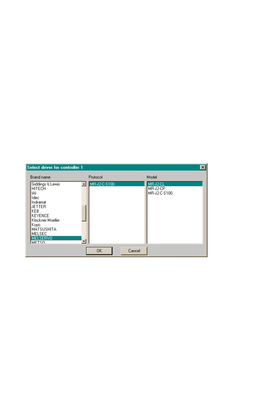
Select Model
Note:
It is very important to choose the correct servo-model for the project. The chosen model
will be transferred to the terminal and will be considered when the terminal reads and
writes the devices.
If the servoprogram is to be read or written from or to the servo, using the terminal it is
very important to choose the correct model between MR-J2-CL and MR-J2-C. The MR-J2-
holds 8 programs and maximum 60 steps while MR-J2-CL holds 16 programs and
maximum 120 steps.
If point table is to be handled by the terminal, the MR-J2-CP must be chosen.
This means that if a MR-J2-CL and a MR-J2-CP is connected to a multidrop, you cannot
both handle the point table and reading and writing servoprograms. If MR-J2-CL is
then servoprogram can be read or written and if MR-J2-CP is chosen then the point table
can be handled.
Sida 4 av 47
Introduction
2003-07-01
file://C:\TEMP\~hhAEEB.htm

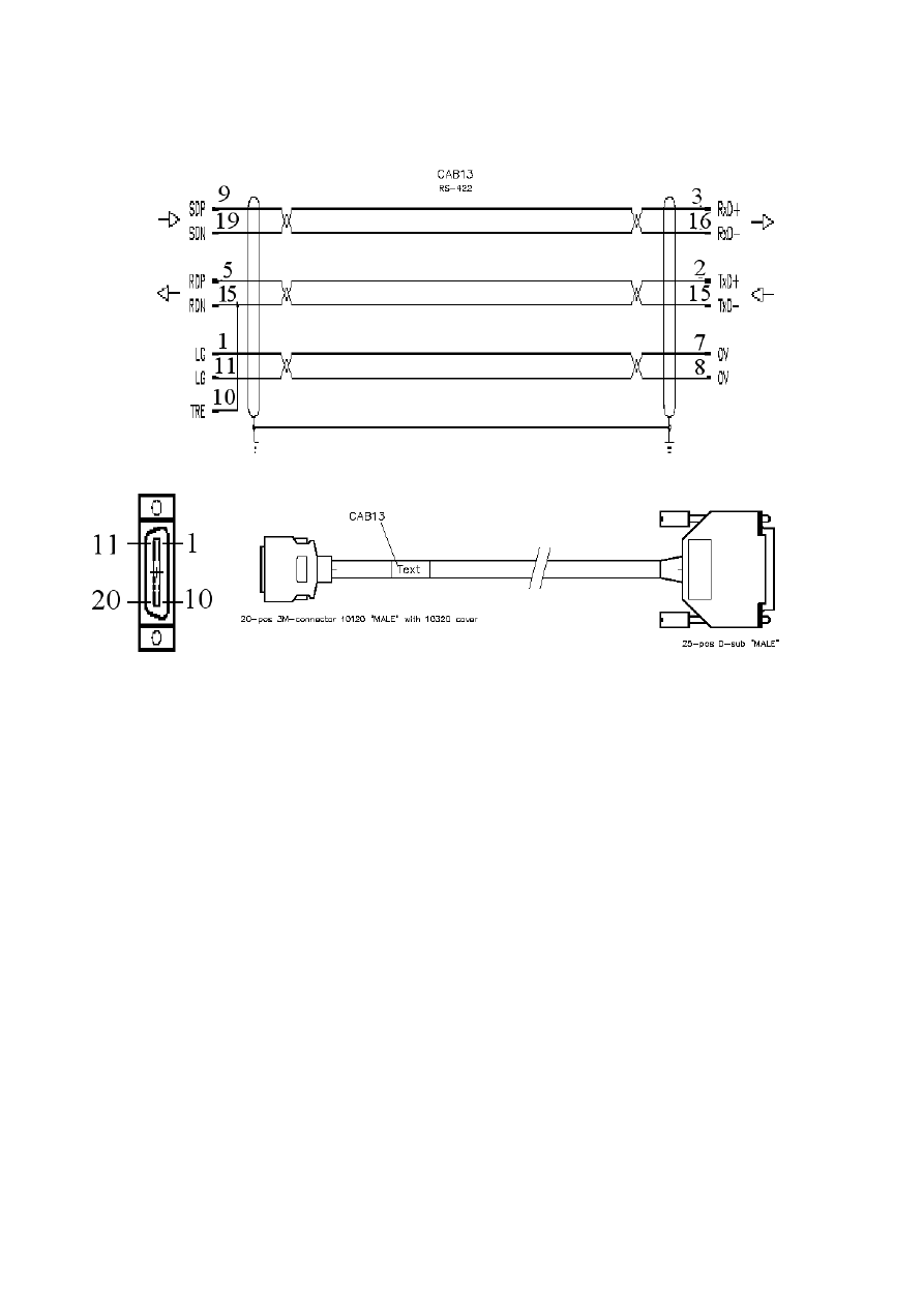
Connecting to the MELSERVO
The connection to the terminal can either be of the type "point to point" or "multidrop".
To connect the terminal RS232, the cable called cable1 is used. To connect to the
controller system RS422 the cable CAB13 are used. CAB13 is a standard cable that can
ordered from Beijer Electronics AB.
For further information about connections we refer to the manual for the MELSERVO.
Sida 5 av 47
Introduction
2003-07-01
file://C:\TEMP\~hhAEEB.htm
RS422
Sida 6 av 47
Introduction
2003-07-01
file://C:\TEMP\~hhAEEB.htm
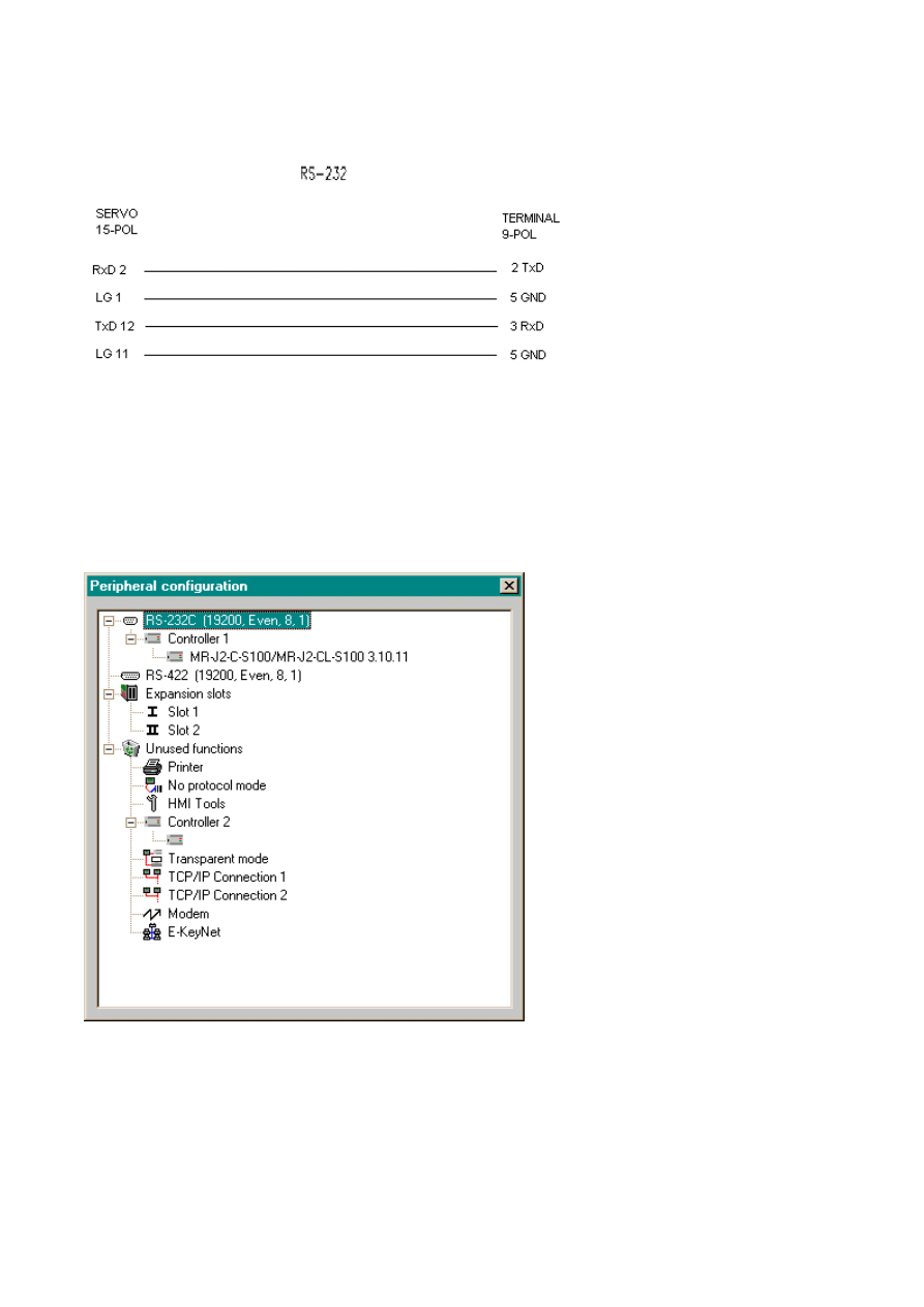
RS232
Communication setup
The settings for the communication between the terminal and the controller are made
under
Setup/Peripherals. Right-click on the controller and select
to change the settings.
Sida 7 av 47
Introduction
2003-07-01
file://C:\TEMP\~hhAEEB.htm

Default settings:
Parameter
Setting
Port
RS232C
Baud rate
*
Data bits
8
Stop bits
1
Parity
None
* For CP-model and CL-model the setting for
Parameter 16 means
RS232
0000 = 9600 Baud, RS-232
0001 = 19200 Baud, RS-232
0002 = 38400 Baud, RS-232
0003 = 57600 Baud, RS-232 ( Does not work due to small difference
between the actual baudrate in servo and terminal)
RS422
0100 = 9600 Baud, RS-422
0101 = 19200 Baud, RS-422
0102 = 38400 Baud, RS-422
0103 = 57600 Baud, RS-422 ( Does not work due to small difference
between the actual baudrate in servo and terminal)
* For C-model, the setting for
16 means
RS232
0100 = 9600 Baud, RS-232
0101 = 19200 Baud, RS-232
0102 = 4800 Baud, RS-232
RS422
0000 = 9600 Baud, RS-422
0001 = 19200 Baud, RS-422
0002 = 4800 Baud, RS-422
Sida 8 av 47
Introduction
2003-07-01
file://C:\TEMP\~hhAEEB.htm
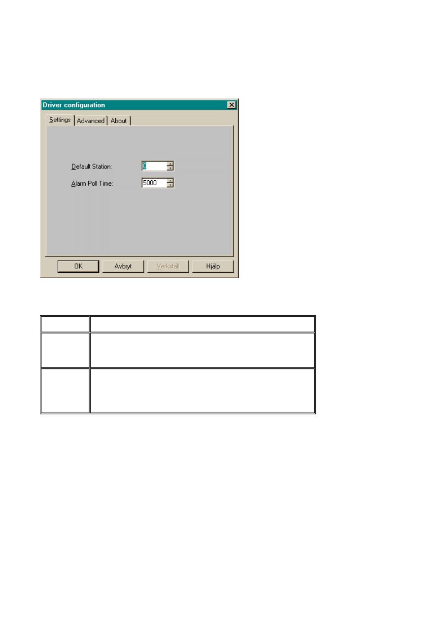
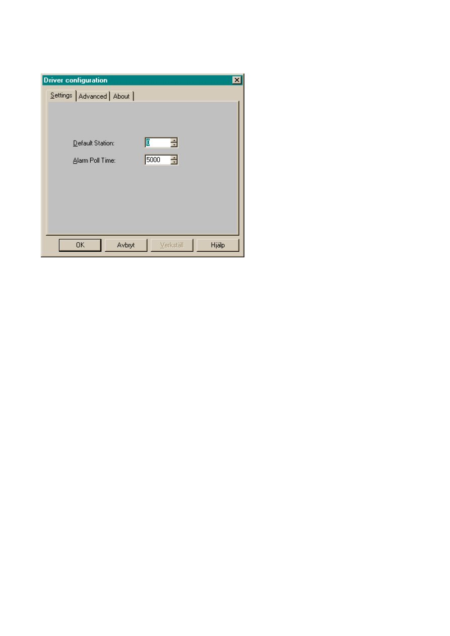
To make specific settings for the selected driver right-click on the driver name and select
Properties.
Parameter Description
Default
station
It is the station to the devices when no station number
is stated. Read more about station handling later in
document.
Alarm Poll
Time
If alarms were to be read from servo, it would be a
large disadvantage to read them all the time. The
Poll Time is the time between two readings of the
alarms.
Sida 9 av 47
Introduction
2003-07-01
file://C:\TEMP\~hhAEEB.htm
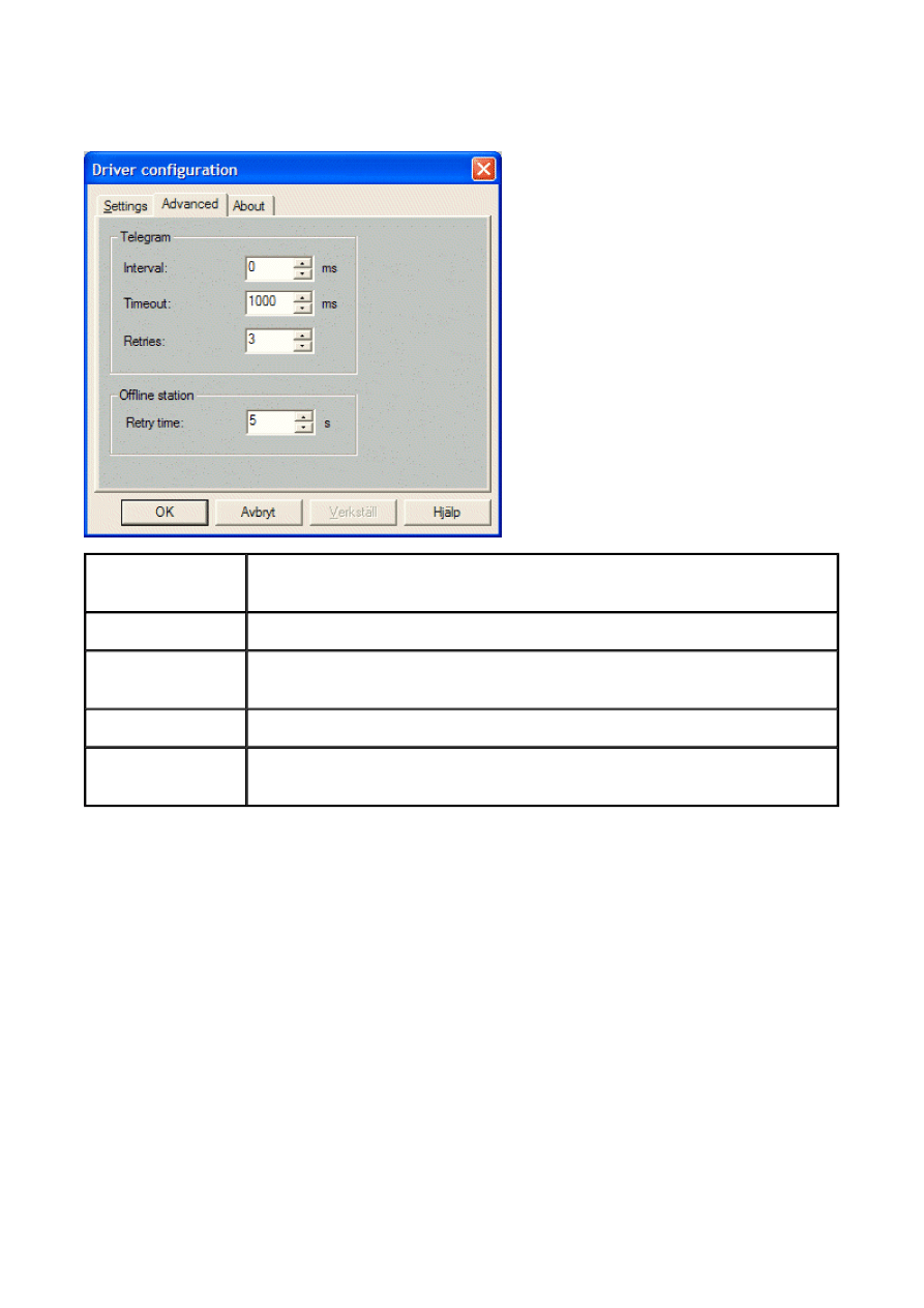
Advanced
Settings for handling communication failures.
Addressing
The driver can handle the following devices. The format in which the value is to be
is free to chose but we recommend that the manual for the MELSERVO is followed. P16
example would be chosen like
Advanced
settings
Description
Interval
The minimum time between communication packages.
Timeout
The number of milliseconds between retries when communication
fails
Retries
Number of retries before a communication error is detected
Retry time
How long to wait after a communication error before trying to
communication
Sida 10 av 47
Introduction
2003-07-01
file://C:\TEMP\~hhAEEB.htm
Digital objects
P0-19
Basic parameters (see MELSERVO manual)
P20-68
P20-90
Special parameters (see MELSERVO manual)
Special parameters for CP-S100 (see MELSERVO
manual)
Sida 11 av 47
Introduction
2003-07-01
file://C:\TEMP\~hhAEEB.htm

Diagnostics devices
Analog signal
Description
V0
Accumulated power on
V1
Power on times
V2
Tuning pos ctrl gain 1
V3
Tuning speed ctrl gain 1
V4
Tuning pos ctrl gain 2
V5
Tuning speed ctrl gain 2
V6
Tuning speed int.comp
V7
Tuning load inertia ratio
V8
Running step no
Sida 12 av 47
Introduction
2003-07-01
file://C:\TEMP\~hhAEEB.htm

Display devices
Analog signal
Description
Description
Description
MR-J2-S100
MR-J2-CP
MR-J2-CL
S0
Current position
Current position
Current position
S1
Commanded position
Commanded position
Commanded position
S2
Commands remaining
distance
Commands remaining
distance
Commands remaining
S3
Program number
Point table number
Program number
S4
Feedback pulse accumulation
Feedback pulse
accumulation
Step number
S5
Motor speed
Motor speed
Feedback pulse accumulation
S6
Droop pulse
Droop pulse
Motor speed
S7
Override
Override
Droop pulse
S8
Torque limit common voltage
Torque limit common
voltage
Override
S9
Regeneration load factor
Regeneration load factor
Torque limit common voltage
S10
Effective load factor
Effective load factor
Regeneration load factor
S11
Peak load factor
Peak load factor
Effective load factor
S12
Position within one rotation
Instant Torque
Peak load factor
S13
ABS Counter
Position within one rotation
Instant Torque
S14
Load/inertia ration
ABS counter
Position within one rotation
S15
Load/inertia ration
ABS counter
S16
Bus Voltage
Load/inertia ration
S17
Bus Voltage
Sida 13 av 47
Introduction
2003-07-01
file://C:\TEMP\~hhAEEB.htm

Digital I/O, Input device
Digital
signal
Servo
Signal
Description
Servo
Signal
Description
Servo
Signal
Description
MR-J2-S100
MR-J2-CP
MR-J2-CL
M0
SON
Servo on
SON
Servo on
SON
Servo on
M1
LSP
Forward stroke end
LSP
Forward stroke end
LSP
Forward stroke end
M2
LSN
Reverse stroke end
LSN
Reverse stroke end
LSN
Reverse stroke end
M3
TL
External torque limit
selection
TL
External torque limit
selection
TL
External torque limit
selection
M4
TL2
Internal torque limit
selection
TL2
Internal torque limit
selection
TL2
Internal torque limit
selection
M5
PC
Proportional control
PC
Proportional control
PC
Proportional control
M6
RES
Reset
RES
Reset
RES
Reset
M10
LPS
Current Position Latch
input
M11
ST1
Forward start
ST1
Forward start
ST1
Forward start
M12
ST2
Reverse start
ST2
Reverse start
ST2
Reverse start
M16
EMG
Emergency stop
EMG
Emergency stop
EMG
Emergency stop
M17
MDO
Automatic / Manual
MDO
Automatic / Manual
MDO
Automatic / Manual
M18
DOG
Proximity
DOG
Proximity
DOG
Proximity
M19
PS0
Program No. selection 1
DI0
Point Table # select 1
DI0
Program No. selection 1
M20
PS1
Program No. selection 2
DI1
Point Table # select 2
DI1
Program No. selection 2
M21
PS2
Program No. selection 3
DI2
Point Table # select 3
DI2
Program No. selection 3
M22
PS3
Program No. selection 4
DI3
Point Table # select 4
DI3
Program No. selection 4
M23
OVR
Override selection
OVR
Override selection
OVR
Override selection
M24
STP
Temporary stop / Restart
STP
Temporary stop /
Restart
STP
Temporary stop / Restart
M25
TP0
Manual pulse generator
multiplier 1
TP0
Manual pulse
generator multiplier 1
TP0
Manual pulse generator
multiplier 1
M26
TP1
Manual pulse generator
multiplier 2
TP1
Manual pulse
generator multiplier 2
TP1
Manual pulse generator
multiplier 2
M27
PI1
Program Input 1
CDP
Gain Switch
CDP
Gain Switch
M28
PI2
Program Input 2
M29
PI3
Program Input 3
DI4
Point Table select 5
PI1
Program Input 1
M30
TCH
Teach
PI2
Program Input 2
M31
PI3
Program Input 3
Sida 14 av 47
Introduction
2003-07-01
file://C:\TEMP\~hhAEEB.htm

Outputs
Digital
signal
Servo
Signal
Description
Servo
Signal
Description
Servo
Signal
Description
MR-
J2-
S100
MR-J2-
CP
MR-J2-
CL
M300
RD
Ready
RD
Ready
RD
Ready
M303
TLC
Torque limit in
effect
TLC
Torque limit in
effect
TLC
Torque limit in
effect
M305
INP
In position
M307
WNG
Warning output
WNG
Warning output
WNG
Warning output
M308
ALM
Alarm
ALM
Alarm
ALM
Alarm
M310
MBR
Electromagnetic
brake
MBR
Electromagnetic
brake
MBR
Electromagnetic
brake
M311
DRB
Dynamic brake
DRB
Dynamic brake
DRB
Dynamic brake
M315
BWNG
Battery
BWNG
Battery
BWNG
Battery
M316
CPO
Rough match
M317
ZP
Z-phase
ZP
Z-phase
ZP
Z-phase
M318
POT
Position range
POT
Position range
POT
Position range
M319
PUS
Temporary
stopping
PUS
Temporary
stopping
PUS
Temporary
stopping
M320
OUT1
Program output
1
PT0
Point No.
Output1
OUT1
Program
Output1
M321
OUT2
Program output
2
PT1
Point No.
Output2
OUT2
Program
Output1
M322
OUT3
Program output
3
PT2
Point No.
Output3
OUT3
Program
Output1
M323
SOUT
SYNC
synchronous
PT3
Point No.
Output4
SOUT
Program
Output1
M324
PED
Movement
complete
PT4
Point No.
Output5
PED
Movement
Complete
Sida 15 av 47
Introduction
2003-07-01
file://C:\TEMP\~hhAEEB.htm

Forcing the Input devices
These signals can be turned ON / OFF forcible. It will be "OR" logic with the external input
Input device
Digital
signal
Servo
Signal
Description
Servo
Signal
Description
Servo
Signal
Description
MR-J2-
S100
MR-J2-CP
MR-J2-CL
M200
SON
Servo on
SON
Servo on
SON
Servo on
M201
LSP
Forward
stroke end
LSP
Forward
stroke end
LSP
Forward
stroke end
M202
LSN
Reverse
stroke end
LSN
Reverse
stroke end
LSN
Reverse
stroke end
M203
TL
External
torque limit
selection
TL
External
torque limit
selection
TL
External
torque limit
selection
M204
TL2
Internal
torque limit
selection
TL2
Internal
torque limit
selection
TL2
Internal
torque limit
selection
M205
PC
Proportional
control
PC
Proportional
control
PC
Proportional
control
M206
RES
Reset
RES
Reset
RES
Reset
M210
LPS
Current
position latch
input
M211
ST1
Forward start
ST1
Forward start
ST1
Forward start
M212
ST2
Reverse start
ST2
Reverse start
ST2
Reverse start
M216
EMG
Emergency
stop
EMG
Emergency
stop
EMG
Emergency
stop
M217
MDO
Automatic /
Manual
MDO
Automatic /
Manual
MDO
Automatic /
Manual
M218
DOG
Proximity
DOG
Proximity
DOG
Proximity
M219
PS0
Program
No.selection 1
DI0
Point Table
No.selection 1
DI0
Program
No.selection 1
M220
PS1
Program
DI1
Point Table
DI1
Program
Sida 16 av 47
Introduction
2003-07-01
file://C:\TEMP\~hhAEEB.htm

No.selection 2
No.selection 2
No.selection 2
M221
PS2
Program
No.selection 3
DI2
Point Table
No.selection 3
DI2
Program
No.selection 3
M222
PS3
Program
No.selection 4
DI3
Point Table
No.selection 4
DI3
Program
No.selection 4
M223
OVR
Override
selection
OVR
Override
selection
OVR
Override
selection
M224
STP
Temporary
stop / Restart
STP
Temporary
stop / Restart
STP
Temporary
stop / Restart
M225
TP0
Manual pulse
generator
multiplier 1
TP0
Manual pulse
generator
multiplier 1
TP0
Manual pulse
generator
multiplier 1
M226
TP1
Manual pulse
generator
multiplier 2
TP1
Manual pulse
generator
multiplier 2
TP1
Manual pulse
generator
multiplier 2
M227
PI1
Program input
1
CDP
Gain switch
CDP
Gain switch
M228
PI2
Program input
2
M229
PI3
Program input
3
DI4
Point Table
select 5
PI1
Program input
1
M230
TCH
Teach
PI2
Program input
2
M231
PI3
Program input
3
Sida 17 av 47
Introduction
2003-07-01
file://C:\TEMP\~hhAEEB.htm

Reading the Input and Output pins
The Servo has a number of external inputs and outputs. They can be read from the following
digital devices.
Inputs
Digital signal
Group
External input
M100
Input pins
CN1B-16
M101
Input pins
CN1B-17
M102
Input pins
CN1B-15
M103
Input pins
CN1B-5
M104
Input pins
CN1B-14
M105
Input pins
CN1A-8
M106
Input pins
CN1B-7
M107
Input pins
CN1B-8
M108
Input pins
CN1B-9
M109
Input pins
CN1A-19
Sida 18 av 47
Introduction
2003-07-01
file://C:\TEMP\~hhAEEB.htm

Outputs
Digital signal
External input
External input
External input
MR-J2-S100
MR-J2-CP
MR-J2-CL
M400
CN1A-19
CN1A-19
CN1A-19
M401
CN1A-18
CN1A-18
CN1A-18
M402
CN1B-19
CN1B-19
CN1B-19
M403
CN1B-6
CN1B-6
CN1B-6
M404
CN1B-4
CN1B-4
CN1B-4
M405
CN1B-18
CN1B-18
CN1B-18
M406
CN1A-14
CN1A-14
Sida 19 av 47
Introduction
2003-07-01
file://C:\TEMP\~hhAEEB.htm

Internal registers
I1 - I8 are internal index registers for indirect addressing of all parameters. Refer to manual for
the terminals for details about index registers. They are reset each time the terminal is
Driverversion up to 3.10.8
Driverversion 3.10.9 and from there on
The I8 has been replaced by a device named STATION
Two devices more are added in this version of the driver
Analog signal
Description
I8
I8 was used to address stations in a multidrop
network. What was held in I8 was the
stationnumber from which the servoprogram
was to be read from and written to. The reading
and acknowledging of servoalarms was also
handled this way by checking the addressed
stationnumber, held in I8.
Analog signal
Description
STATION
The value held in the device STATION will
from what stationnumber servoprogram and
alarms will be read from and written to. I8 now
works as ordinary index like I1-I7.
Digital signal
Description
AREADOFF
The time between the readings of alarms from
the servo can be set in peripherals for the
(The Alarm Poll Time).
We can now also disable the reading of the
alarms by setting the device AREADOFF to 1.
COMMERR
The value held in the device STATION will
from what stationnumber servoprogram and
alarms will be read from and written to. I8 now
works as ordinary index like I1-I7.
Sida 20 av 47
Introduction
2003-07-01
file://C:\TEMP\~hhAEEB.htm

Indirect addressing
The terminals can handle the four indirect registers. These are assigned as follows:
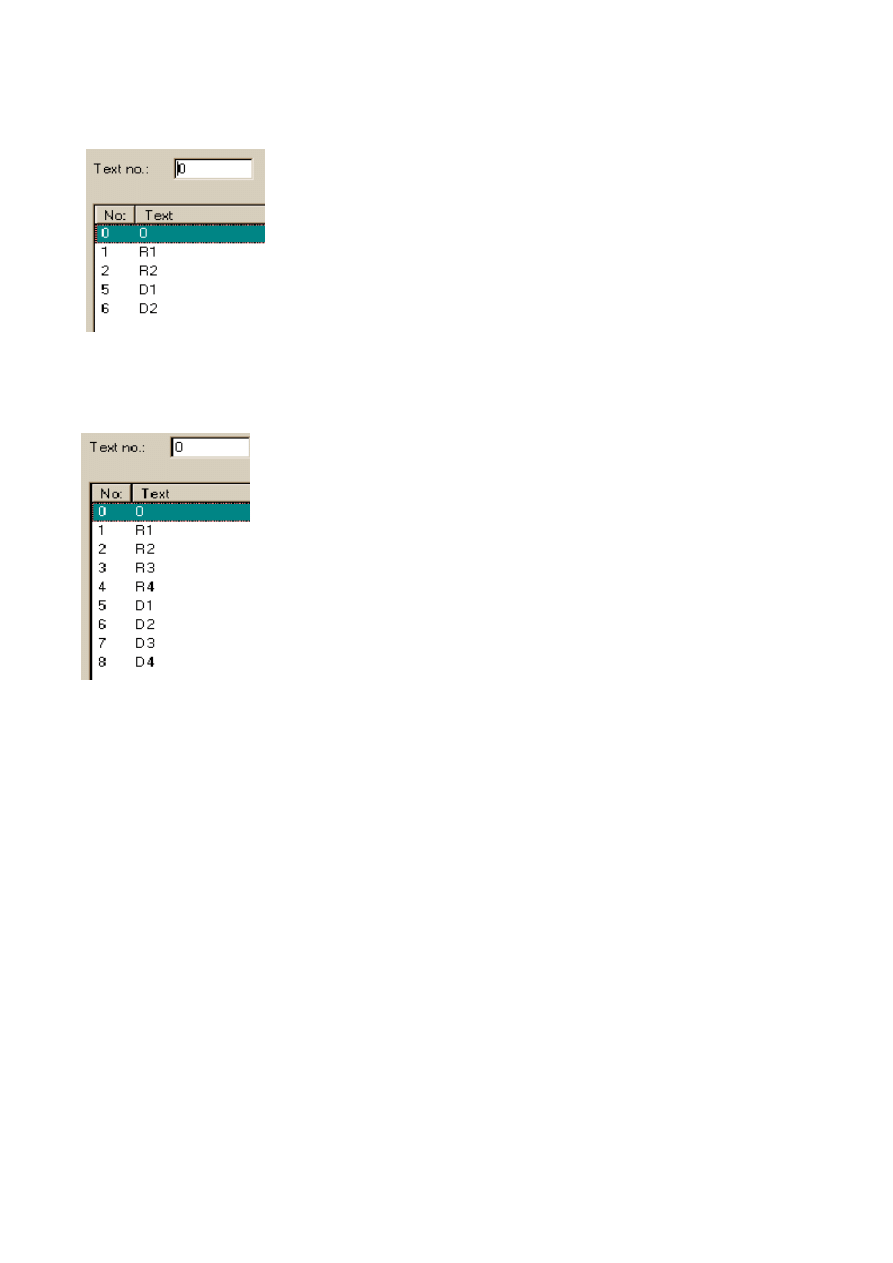
E1 - 2 is the same as R1 - 2, but the value is stored in EEPROM instead of RAM.
In a CL-servo, R1-R4, D1-D4 and E1-E4 can be handled.
Servo Program
There has been a change in how the reading and writing of servoprogram and how
alarmreading is handled. Driverversions up to 3.08 can only read and write
and handle servoalarms if
the terminals E100, E150, E200, E300 and E600 are used.
Driverversion up to 3.08
Editing the MR-J2-C-S100 servo program
Only valid in The MR-J2-C-S100 can handle up to 8 programs with 60 steps in total.
All editing is made in the special block 995.
Create a block jump to block number 995.
If several servos are connected in network, index register I8 can be used to select which
station to edit the program in.
Analog signal
Stored in
RAM
EEPROM
D1 - 2
X
R1 - 2
X
E1 - 2
X
Sida 21 av 47
Introduction
2003-07-01
file://C:\TEMP\~hhAEEB.htm

When entering block 995 nREADING PROGRAMn will be shown together with xx %
completed.
In block 995 it is possible to choose program number, insert line, delete
line and add commands.
The program number P, program step S and total steps T are shown to the left on the
display.
Use the function keys to choose program number, insert or delete a line. To add a new
command press the ENTER key.
The servo commands are shown in a list. Use the cursor keys to move up and down and
press ENTER to select command.
To exit block 995 in E100, press NUM and ENTER.
Available commands
Please refer to the MELSERVO manual for descriptions.
Press MAIN to leave the editing area.
In E100, F4 means Edit Program. NUM+ENTER means that we go to previous block and
the servoprogram is written.
Note:
It is not possible to: 1.
Create the block 995 2.
See the block 995 in E-
Designer. Add any text
or objects into block
995.
Block 995 is an internal
block in the terminals.
NOP (No operation)
OUTOF
STOP
SPN
TIM
STC
TIMES
STA
TRIP
STB
COUNT
MOV
SYNC
MOVA
OUTON
ZRT
Sida 22 av 47
Introduction
2003-07-01
file://C:\TEMP\~hhAEEB.htm

In E100, Back (5) + Arrow Left means that we go to previous block and do not write the
servoprogram.
In E150, F5 means Edit Program.
In E150, Back (Arrow) means that we go to previous block and do not write the
servoprogram.
In E150, F1 means that we go to previous block and the servoprogram is written.
The other terminals
If any changes are made to the program it will be automatically be downloaded to the
servo when exiting.
Servo alarm handler
The built in alarm handling in the MR-J2-C-S100 is used. Up to 6 alarms are stored in
servo.
When an alarm occurs the nALARMn message is shown in the upper corner.
To view the alarms press the nLISTn key.
The current alarm is displayed with C as prefix.
Use the function keys to view the alarm time or to reset an alarm.
The servo power needs to be switched OFF and ON to clear a reset alarm in the
If several servos are connected in network, index register I8 can be used to select which
station to display the alarm list from.
Driverversion 3.09 and from there on
Editing the MR-J2-C-S100 servo program
These are devices that are only valid to use when MR-J2S-C-S100, and MR-J2S-CL are
connected (not MR-J2S-CP).
Note:
If servoprograms are going to be written using the terminal then always do a SREAD
before editing the servoprogram and the do a SWRITE to write the new program to the
servo. The terminal does not hold a default-program at power-up and if not SWRITE is
before program is edited then one of the programs 1-8 (or 1-16) can be corrupt when
writing.
Analog signal
Description
STATION
The value held in the device STATION will
from what stationnumber servoprogram and
alarms will be read from and written to. I8 now
works as ordinary index like I1-I7.
Sida 23 av 47
Introduction
2003-07-01
file://C:\TEMP\~hhAEEB.htm

If the device STATION is not used, then the stationnumber set under peripherals in the
project is used.
Digital signal
Decription
SREAD
Triggs the reading of the servo
program.
SWRITE
Triggs the writing of the servo
program.
Sida 24 av 47
Introduction
2003-07-01
file://C:\TEMP\~hhAEEB.htm

Analog signal
Decription
SINSTR
Servo Program Instuction
SVALUE
Servo Program Value connected
to instruction
STYPE
Servo Program, if R1, R2, D1 or
D2 is used (see below)
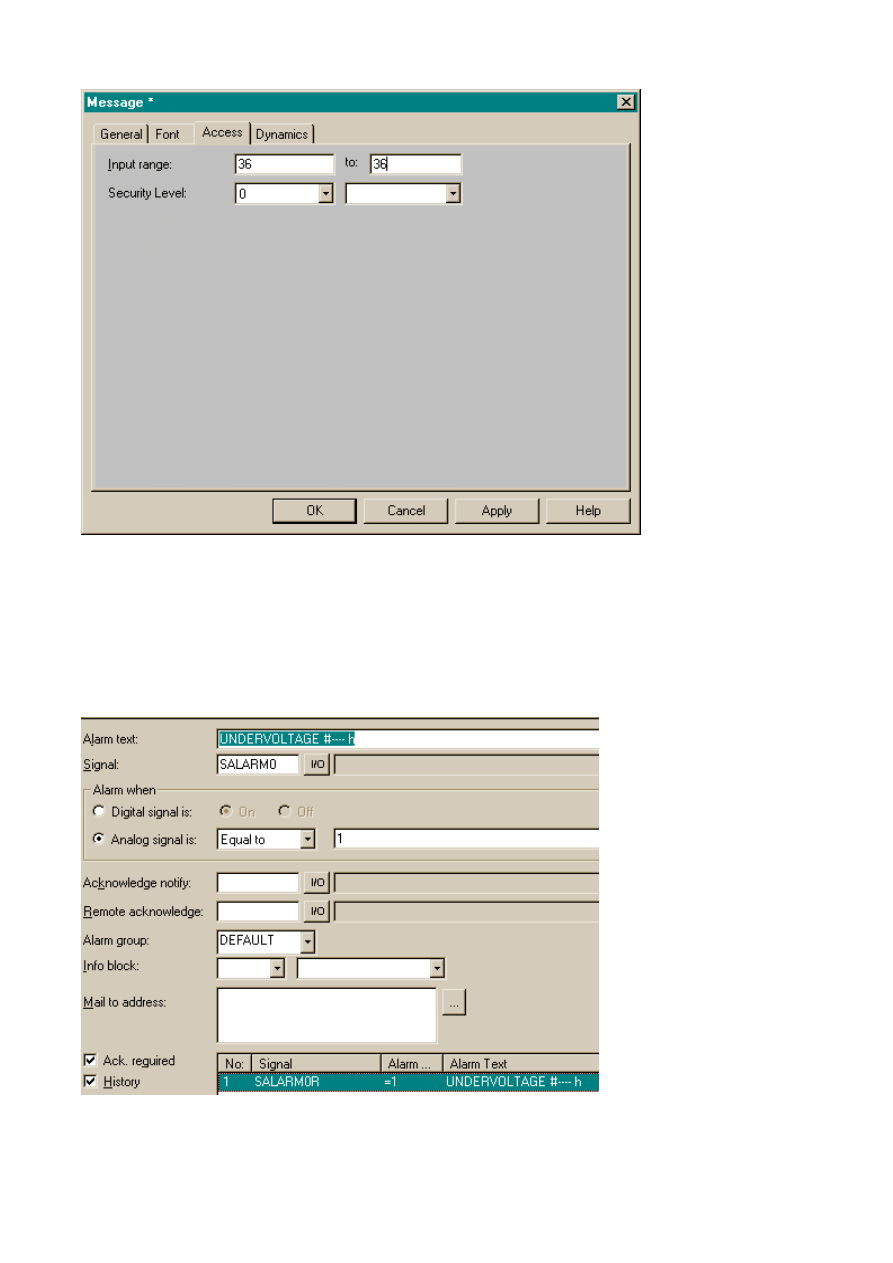
SALARM
An analog device where the
values from the
servoalarmhandler can be seen.
Every bit represents a certain
alarmevent. The device can be
handled bitwise (SALARM0.1-
SALARM0.23 hexadecimal)
are 35 different alarmtypes and
seven history alarmevents
(SALARM0-SALARM6) see below
SALARMTIME
The time of the alarmevent can
be shown by using
SALARMTIME0 - SALARMTIME6.
Sida 25 av 47
Introduction
2003-07-01
file://C:\TEMP\~hhAEEB.htm
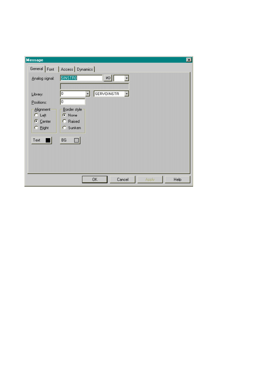
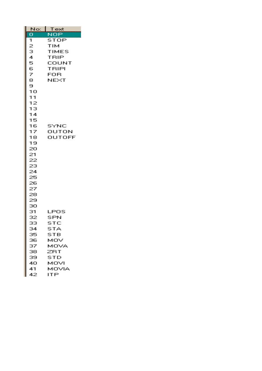
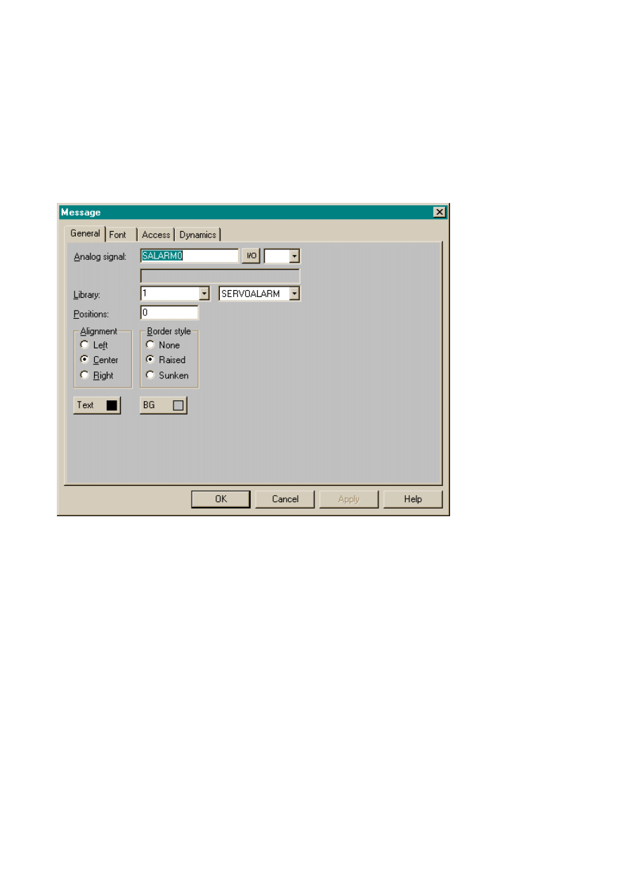
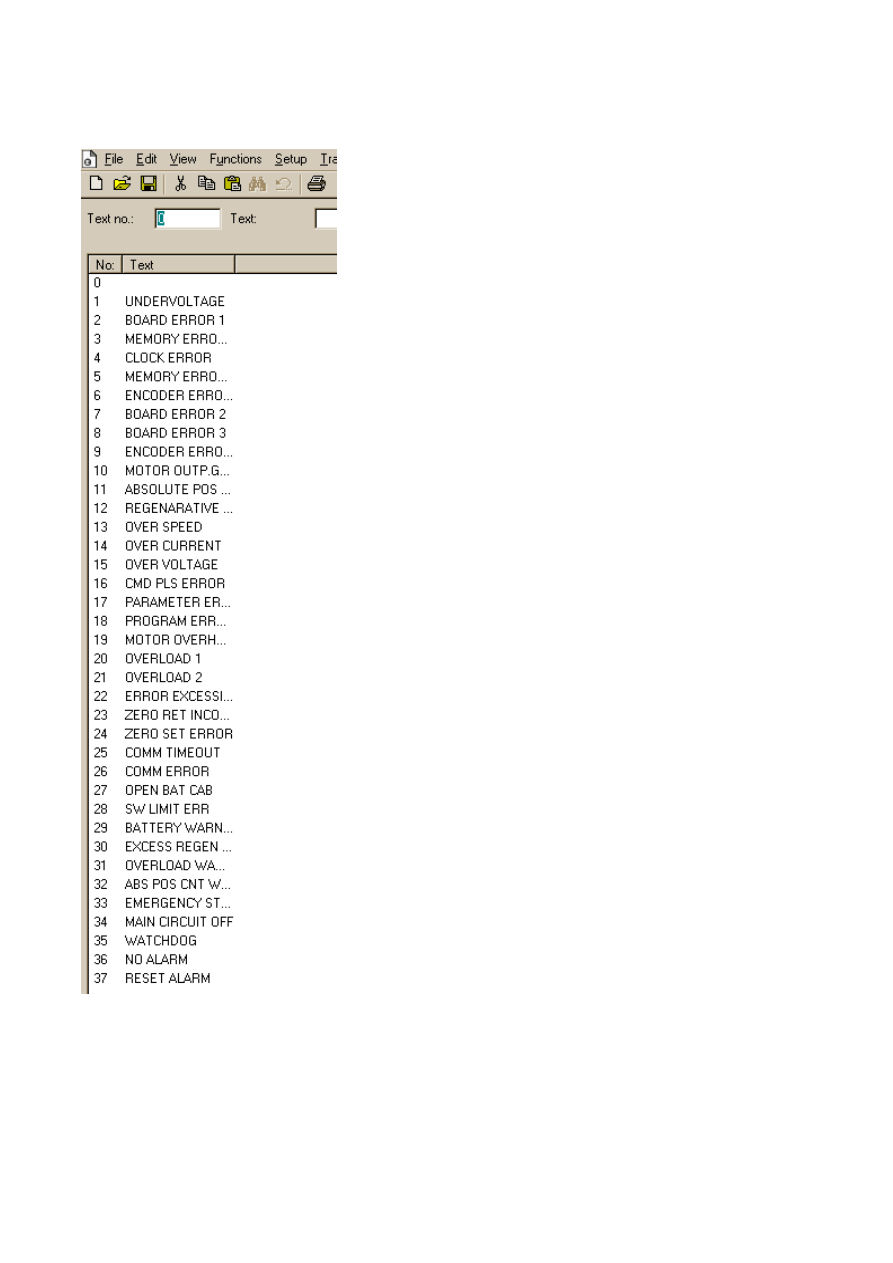
SINSTR ought to be connected to a messagelibrary like below
The messagelibrary should then look like
Sida 26 av 47
Introduction
2003-07-01
file://C:\TEMP\~hhAEEB.htm
Sida 27 av 47
Introduction
2003-07-01
file://C:\TEMP\~hhAEEB.htm

Only if MR-J2S-CL -servo the instructions below can be used if it is MR-J2-C-S100 that is
connected, then these instructions can be excluded from the messagelibrary.
The order of the instructions must be as shown above and the empty spaces left
NEXT and SYNC, for example are meant to be there.
The STYPE must be connected to a message library. If STYPE holds other than the value
0, then SVALUE is ignored when writing the servoprogram to the unit. If you know that
the servoprogram does not use R1, R2, D1 or D2, (R1-R4, D1-D4 for CL-servo) then you
do not have to have any objects connected to the STYPE in the block.
STD
FOR
NEXT
MOVI
LPOS
TRIPI
ITP
MOVIA
Sida 28 av 47
Introduction
2003-07-01
file://C:\TEMP\~hhAEEB.htm
The message library must look like this if a MR-J2-C-S100-servo is connected.
and if a MR-J2S-CL-servo is connected the messagelibrary should look like
A MR-J2-C-S100-servo can hold 8 programs with a total count of 60 steps. The first
program is held by SINSTR0-SINSTR59, SVALUE0-SVALUE59 and STYPE0-STYPE59.
The next program SINSTR60-SINSTR119, SVALUE60-SVALUE119 and STYPE60-
and so on.
These devices can be used with index, try SINSTR0I1 (Index1 has to be connected to I1
the project) then have a key add 60 to I1 when pressed and another to subtract 60 from
I1 when pressed.
A MR-J2S-CL -servo can hold 16 programs with a total count of 120 steps. The first
program is held by SINSTR0-SINSTR119, SVALUE0-SVALUE119 and STYPE0-STYPE119.
The next program SINSTR120-SINSTR239, SVALUE120-SVALUE239 and STYPE120-
STYPE239 and so on.
Sida 29 av 47
Introduction
2003-07-01
file://C:\TEMP\~hhAEEB.htm
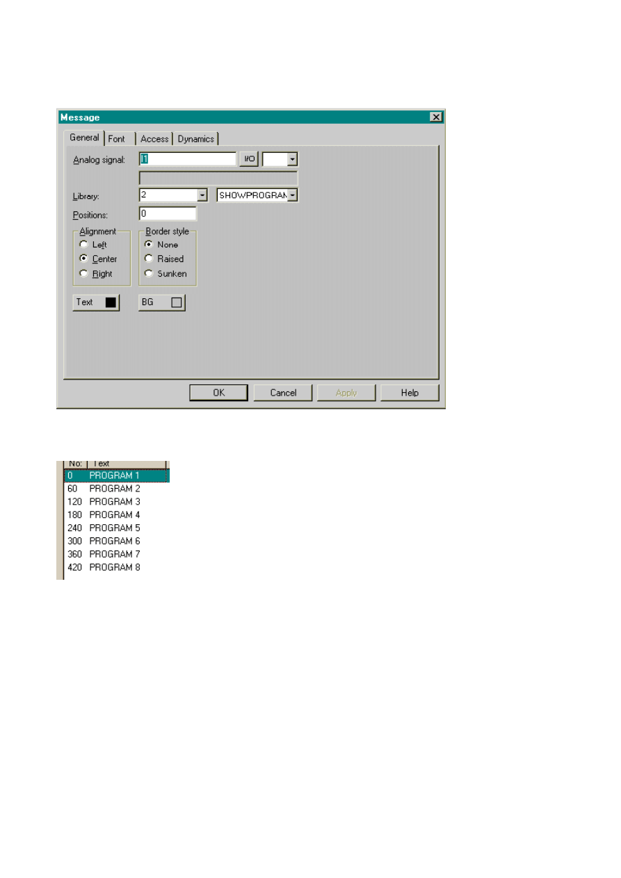
A messagelibrary could be created to show what program is shown in the indexed
The message Library for showprogram for MR-J2-C-S100 should look like
Sida 30 av 47
Introduction
2003-07-01
file://C:\TEMP\~hhAEEB.htm

and for MR-J2S-CL-servo
If you also want to be able to chose the program through the use of a message library, a
special device has to be used see PRGNBR1 below, PRGNBR1-PRGNBR8 can be used. If
Index 1 is used to address the SINSTR, SVALUE and STYPE then PRGNBR1 should be
used. If Index 2 is used to address the SINSTR, SVALUE and STYPE then PRGNBR2
be used and so on.
Sida 31 av 47
Introduction
2003-07-01
file://C:\TEMP\~hhAEEB.htm
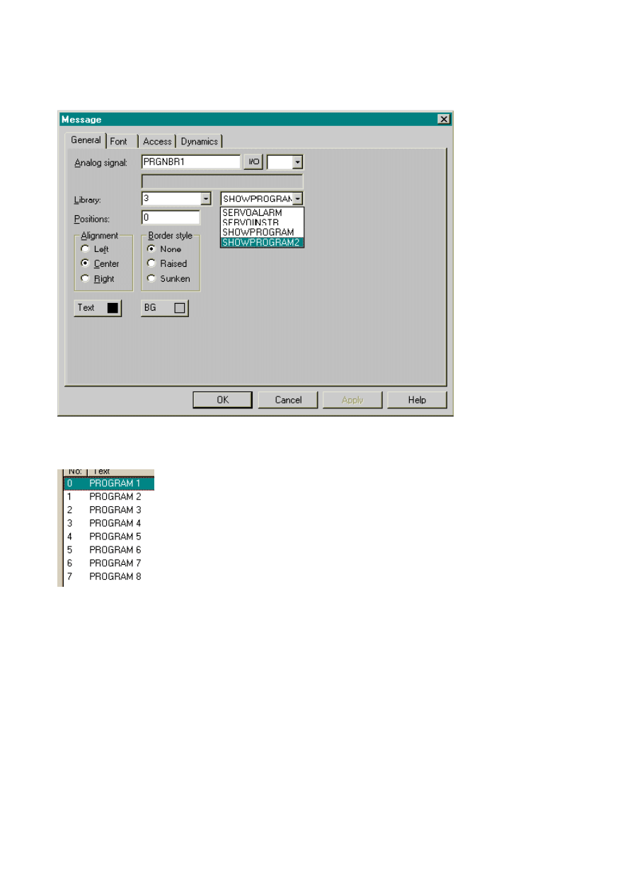
PRGNBR is then connected to a message library like below
The message library for MR-J2-C-S100-servo looks like
Sida 32 av 47
Introduction
2003-07-01
file://C:\TEMP\~hhAEEB.htm
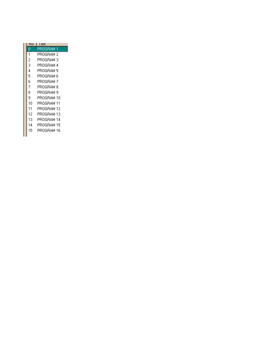
And for MR-J2S-CL-servo
This special device (PRGNBR) works like this.
If MR-J2-C-S100-servo is chosen then when PROGRAM1 is chosen, the value 0 is forced
into I1, when PROGRAM2 is chosen, the value 60 is forced into I2 and so on.
If MR-J2S-CL-servo is chosen then when PROGRAM1 is chosen, the value 0 is forced into
I1, when PROGRAM2 is chosen, the value 120 is forced into I2 and so on.
Sida 33 av 47
Introduction
2003-07-01
file://C:\TEMP\~hhAEEB.htm

Remember that when a new value is written to SINSTR, SVALUE or STYPE, the
internal values are changed, not the values in the servo. When SWRITE is set to 1 (it will
be changed back to 0 by the terminal), then the values are written to the servo. This
be remembered when dataexhange and recipes are used, the values then has to be
written to the servo by the operator after an exchange or a reading of a recipe.
If SWRITE is set by the operator, we would recommend that the operator sets SREAD
after the SWRITE to check if the servoprogram has been recieved correctly by the servo.
The terminal cannot contain any debug-help concerning the writing of the servoprogram,
like the one the pc-software can.
There is one devices that always holds the value 1, this can be used when a
has been performed and we want the terminal to write the new values to the servo. If a
marco first triggs the exchange and last triggs an exchange TRIGG->SWRITE then we
know that the values are written.
Servo Alarms
Driverversion 3.09 and from there on
Servo alarm handler
The servo has a history of seven alarmevents. These are read by adding the device
SALARM to the project. To be able to show all seven alarms and whatever code they
many devices has to be added to the alarms in the project. Only seven questions are
to the servo not 7*36 (the number of alarmdevices added in the project) so it will not
down the terminal much.
Everyone of the seven alarmevents can hold one of the codes below
This is an example of the first event SALARM0
Digital signal
Group
Decription
TRIGG
Always the value 1. Use like
written below for example.
MR-J2-C/ CL
MR-J2-CP
Sida 34 av 47
Introduction
2003-07-01
file://C:\TEMP\~hhAEEB.htm

SALARM0.1
Undervoltage
Undervoltage
SALARM0.2
Board error 1
Memory error 1
SALARM0.3
Memory error 1
Clock error
SALARM0.4
Clock error
Memory error 2
SALARM0.5
Memory error 2
Encode error 1
SALARM0.6
Encode error 1
Board error
SALARM0.7
Board error 2
Memory error 3
SALARM0.8
Board error 3
Motor combination error
SALARM0.9
Encoder error 2
Encoder error 2
SALARM0.A
Motor outp.gr.f
Main circuit error
SALARM0.B
Absolute pos erase
Absolute pos erase
SALARM0.C
Regenarative error
Regenarative error
SALARM0.D
Over speed
Over speed
SALARM0.E
Over current
Over current
SALARM0.F
Over voltage
Over voltage
SALARM0.10
Cmd pls error
Cmd pls freq error
SALARM0.11
Parameter error
Parameter error
SALARM0.12
Program error
Main circuit device overheat
SALARM0.13
Motor overheat
Servo motor overheat
SALARM0.14
Overload 1
Overload 1
SALARM0.15
Overload 2
Overload 2
SALARM0.16
Error excessive
Error excessive
SALARM0.17
Zero ret incompl
Serial communication time-out
error
SALARM0.18
Zero set error
Serial communication error
SALARM0.19
Comm timeout
Home position return complete
SALARM0.1A
Comm error
Open battery cable warning
SALARM0.1B
Open batt cab
Home position setting warning
SALARM0.1C
SW limit err
Software limit warning
SALARM0.1D
Battery warning
Battery warning
SALARM0.1E
Excess regen warn
Excess regen warn
Sida 35 av 47
Introduction
2003-07-01
file://C:\TEMP\~hhAEEB.htm

SALARM0.1F
Overload warning
Overload warning
SALARM0.20
Abs pos cnt warn
Abs pos cnt warn
SALARM0.21
Emergency stop
Emergency stop
SALARM0.22
Main circuit off
Main circuit off
SALARM0.23
Watchdog
Watchdog
SALARM0.24
No alarm
No alarm
Sida 36 av 47
Introduction
2003-07-01
file://C:\TEMP\~hhAEEB.htm
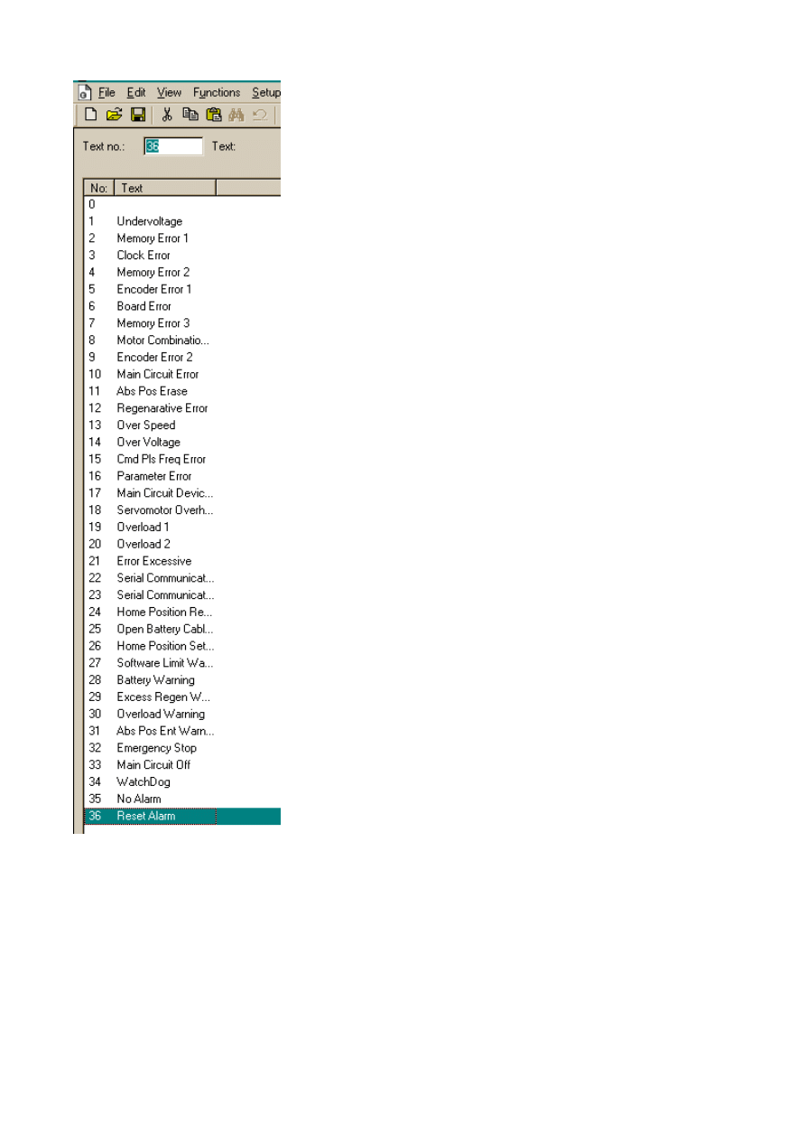
The second event would be SERVOALARM1
SALARM1.1 Undervoltage, SALARM0.2 Board error 1, … SALARM1.24 No alarm
SALARM0-SALARM6 can be connected to a message library, the example below is for MR-J2-
and MR-J2-CL
Sida 37 av 47
Introduction
2003-07-01
file://C:\TEMP\~hhAEEB.htm
Like below
If we write to the device SALARM, the terminal will send the reset alarm command so
SALARM0 connected to the messagelibrary could be set like
Sida 38 av 47
Introduction
2003-07-01
file://C:\TEMP\~hhAEEB.htm
One for MR-J2-CP-S100 would look like
Sida 39 av 47
Introduction
2003-07-01
file://C:\TEMP\~hhAEEB.htm
If we write to the device SALARM, the terminal will send the reset alarm command so
SALARM0 connected to the messagelibrary could be set like
Sida 40 av 47
Introduction
2003-07-01
file://C:\TEMP\~hhAEEB.htm
If the alarms from the servo is to be added to the ordinary alarmhandler it could be done like
below
The device added in the Alarm Text is SALARMTIME0.
Sida 41 av 47
Introduction
2003-07-01
file://C:\TEMP\~hhAEEB.htm

This could be done if the terminal has support for Analog signal alarms. In the smaller
the bit has to be used like
Sida 42 av 47
Introduction
2003-07-01
file://C:\TEMP\~hhAEEB.htm
Station handling
The default station is the station addressed when no station number is stated in front of
devicename. For communication with the other stations, the station number is given as
prefix to the device. This is a fixed number. Example: 3:P0 addresses parameter 0 in
servo with the stationnumber 3.
In the servo, parameter 15 holds the stationnumber.
Beware that servoprogram-reading and writing and servoalarm-reading and
acknowledging is handled in another way concerning the station addressed. Read more
this help-file.
Sida 43 av 47
Introduction
2003-07-01
file://C:\TEMP\~hhAEEB.htm
Point Table
Driverversion 3.09 and from there on
These are some devices that are only valid to use when a MR-J2S-CP (Super
Series) is connected.
In point table there are 6 columns, (Position, Acc-Time,Dec-Time, Dwell-Time, Aux-Func), these
are all accessed by using the device PT.
* The device for postion (PT1.1, PT2.1, PT3.1…) should match what is set in parameter 1 when
comes to the number of decimals. The values for parameter 1 is 0030 = 0 decimals, 0020 = 1
decimal, 0010 = 2 decimals, 0000 = 3 decimals. (see manual for the servo).
The pointtable is read and written to the
stationnumber set under peripherals in the project.
If the pointtable is to be read from another station, then the stationnumber is put in
of the device, like 03:PT1.1 (reads first row, position from stationnumber 3).
Analog signal
Decription
PT1.1
First row, Position *
PT1.2
First row, Speed
PT1.3
First row, Acc-Time
PT1.4
First row, Dec-Time
PT1.5
First row, Dwell-Time
PT1.6
First row, Aux-Func
Digital signal
Decription
TRIGG
Always the value 1. Can be
by the project as you like.
Sida 44 av 47
Introduction
2003-07-01
file://C:\TEMP\~hhAEEB.htm

Efficient Communication
To make the communication between the terminal and the motion controller quick and
efficient the following should be noted about how the signals are read and how the
can be optimized.
Signals affecting the communication time
Only signals to objects in the current block are read continuously. Signals to objects in
other blocks are not read, thus the number of blocks does not affect the communication
time
Besides the signals to objects in the current block, the terminal reads the following
from the motion controller continuously:
Display signals (Block Header)
Print signals (Block Header)
LED registers
Alarm signals
Remote acknowledge signals on alarms and alarm groups
Login signal (Passwords)
Logout signal (Passwords)
Registers for trend curves
Bargraph registers if using min/max indicators
New display register
Buzzer register
Backlight signal
Cursor control block
Recipe control block
Library index register
Index registers
Controller clock register if the controller clock is used in the terminal
List erase signal (Alarm Settings)
No protocol control register
No protocol on signal
Signals not affecting the communication time
The following signals do not affect the communication time:
- Signals linked to function keys
- Time channels
- Objects in alarm messages
Sida 45 av 47
Introduction
2003-07-01
file://C:\TEMP\~hhAEEB.htm
How to make the communication more efficient
Efficient block changes
Block changes are carried out most rapidly and efficiently through the block jump
on the function keys or through a jump object. "Display signals" in the block header
should only be used when the controller is to force the presentation of another block.
"New Display" register can also be used if the controller is to change the block. This does
not affect communication as much as a larger number of "Display signals".
Use the clock of the terminal
An extra load is put on communication if the clock of the controller is used since the
register must be read to the terminal. Downloading of the clock to the controller also
creates an extra load. The interval between downloads should therefore be as long as
possible.
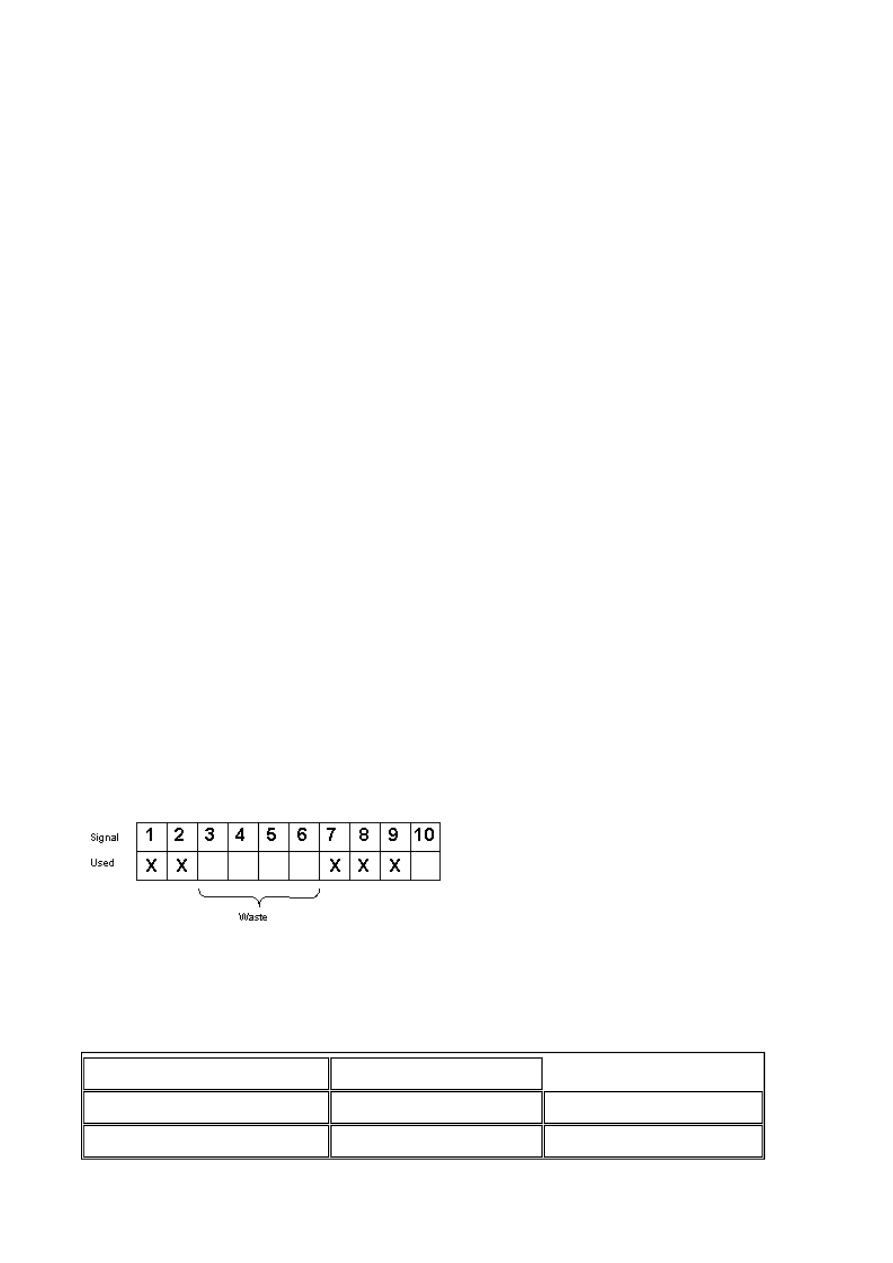
Group controller devices consecutively
The devices from the controller are read most rapidly if all devices are consecutive. If
devices are spread out (e.g. 4, 17, 45, etc.) the updating is slower.
Packaging of signals
When the devices are transferred to the controller, all devices are not transferred
simultaneously. Instead they are divided into packages with a number of devices in each
package. To decrease the number of packages that have to be transferred and make the
communication faster this number has to be considered. The number of devices in each
package depends on the used driver.
To make the communication as fast as possible the number of packages has to be
minimized. Consecutive devices require a minimum of used packages but it is not always
possible to have consecutive signals. In such cases the so-called waste between two
signals has to be considered. The waste is the maximum distance between two signals
can have and still keep them in the same package. The waste depends on the used
Efficient packaging of signals
To make the communication quick and efficient the following should be noted about how
the devices (signals) are read and what that can be done to optimize the reading.
Analog signals
Digital signals
No. of signals/package
1
1
Waste
0
0
Sida 46 av 47
Introduction
2003-07-01
file://C:\TEMP\~hhAEEB.htm

Error messages
Shown in uper left corner of display
If the terminal tries to write a servoprogram that is larger than allowed count of steps,
this will be prevented by the terminal by showing a SYSTEM ERROR message. This will
then result in a reboot of the terminal.
The message looks like
The count of steps is different for various types of servo-systems.
The reason is that to many steps are used. If the servoprogram is not read before
then this problem can occour when trying to wriite to the servo.
Connect a pc to the servo and try to do the same with pc-software from Mitsubishi
Electric.
Error message
Explanation
1:Comm Err Stn X
2:Comm Err Stn X
Communication fails, check
baudrate in terminal and
connected unit. Check cable.
Maybe a device has a non valid
stationnumber or the default
stationnumber for the driver is
set to a stationnumber that is
not connected.
1:… means that it is driver 1
2:… means driver 2
SYSTEM ERROR
Program > 120 Steps
[Enter]:restart
Sida 47 av 47
Introduction
2003-07-01
file://C:\TEMP\~hhAEEB.htm
Document Outline
- Driver for MELSERVO MR-J2
Wyszukiwarka
Podobne podstrony:
CAN Bus Drivers for Atmel C51 Products
Eleanor Cameron Mushroom Planet 04 A Mystery for Mr Bass
On The Specification Of Moving Coil Drivers For Low Frequency Horn Loaded Loudspeakers (W Marshall L
driver for epson workforce 520
apple magic mouse driver for windows 8
wifi drivers for windows 7 on macbook pro
Dynamic gadolinium enhanced subtraction MR imaging – a simple technique for the early diagnosis of L
Data Rescue II (for mac) SN
The Talented Mr Ripley Lulllaby For Cain
USB to RS232 for MAC DOC
driver printer brother dcp 195c for windows 7
Parallels Desktop for Mac Quick Start Guide
więcej podobnych podstron