
Initial Print Date: 10/06
Table of Contents
Subject
Page
Comfort Opening and Closing . . . . . . . . . . . . . . . . . . . . . . . . . . . . . . . . . .12
Anti-Trap Mechanism . . . . . . . . . . . . . . . . . . . . . . . . . . . . . . . . . . . . . . . . . .13
Panic Mode . . . . . . . . . . . . . . . . . . . . . . . . . . . . . . . . . . . . . . . . . . . . . . . . . . .13
Load Shut-Down, Terminal 50 . . . . . . . . . . . . . . . . . . . . . . . . . . . . . . . . . .14
Thermal Protection . . . . . . . . . . . . . . . . . . . . . . . . . . . . . . . . . . . . . . . . . . . .14
E70 Power Windows
Revision Date:

2
E70 Power Windows
Power Windows
Model: E70
Production: From Start of Production
After completion of this module you will be able to:
• Understand and explain the power window system used in the E70 X5

3
E70 Power Windows
The E70 has been fitted with electric power windows since the start of series produc-
tion.
All power windows are equipped with an indirect anti-trap mechanism through the use of
hall sensors mounted inside each motor assembly. The electric power windows have the
following functions:
• Opening and closing
• One-touch / Toll opening and closing
• Comfort opening and closing
Introduction
4
E70 Power Windows
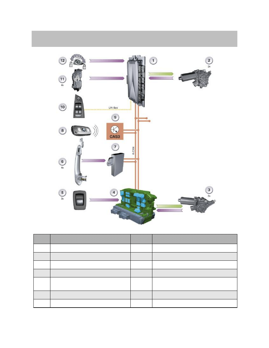
System Overview
Index
Explanation
Index
Explanation
1
Footwell module
8
ID transmitter
2
Power window motor, front doors
9
Car Access System 3 CAS 3
3
Power window motor, rear doors
10
Driver's door switch cluster
4
Junction box control unit
11
Lock with door contact
5
Power window switch, driver's side rear/pas-
senger side front and rear
12
Lock cylinder, driver's door
6
Outside door handle for Comfort Access
K-CAN
Body CAN
7
Comfort Access
Bus-LIN
Local interconnected network bus
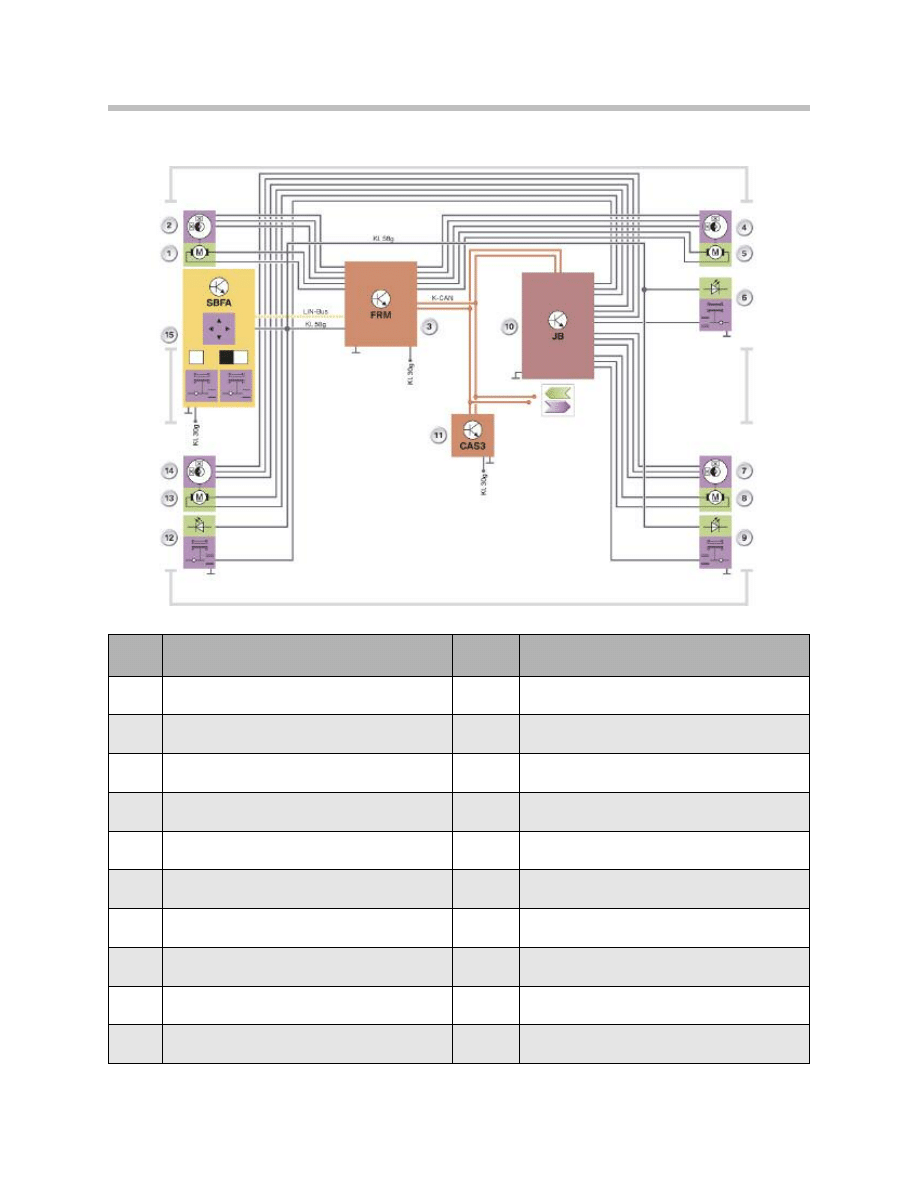
System Circuit Diagram
5
E70 Power Windows
Index
Explanation
Index
Explanation
1
Driver's door power window motor
11
Car Access System 3 CAS 3
2
Indirect anti-trap mechanism,
driver's door power window
12
Power window switch,
driver's side rear
3
FRM footwell module
13
Power window motor, driver's side rear
4
Indirect anti-trap mechanism,
passenger side front power window
14
Indirect anti-trap mechanism,
driver's side rear power window
5
Power window motor, passenger side front
15
SBFA driver's door switch cluster
6
Power window switch,
passenger side front
K-CAN
Body CAN
7
Indirect anti-trap mechanism,
passenger side rear
KL. 30g
Terminal 30 switched
8
Power window motor,
passenger side rear
KL. 58g
Terminal 58 switched
9
Power window switch,
passenger side rear
LIN-Bus
Local interconnected network bus
10
JB junction box control unit

6
E70 Power Windows
The Car Access System 3 (11) issues the enable to actuate the power window motors
(1, 5, 8 and 13).
If a power window switch is then activated, the footwell module (3) (front power window
motor) or the junction box control unit (10) (rear power window motor) executes the
desired request.
Examples of the Window Switch Signal Path
The following examples of a signal path show the path taken by the signal before the
power window motor opens or closes the window. A requirement is that the Car Access
System 3 has issued the enable for operation of the power windows.
Driver's Door
When the power window switch for the window in the driver's door or front passenger 's
door is operated, the signal is routed via the LIN bus to the footwell module. The footwell
module drives the corresponding power window motor.
The signal is routed from the driver's door switch cluster via the LIN bus to the footwell
module when the power window switches for the windows in the rear doors are operated.
The footwell module sends the signal via the K-CAN to the junction box control unit. The
junction box receives the signal and activates the corresponding power window motor.
Front Passenger's Door
The signal is routed to the junction box control unit when the power window switch in the
front passenger's door is operated.
The junction box control unit sends the signal via the K-CAN to the footwell module.
The footwell module controls the power window motor.
Rear Doors
When the power window switches in the rear doors are operated, the signal is routed to
the junction box control unit. The junction box control unit drives the power window
motor.
K-CAN Signals on Roof Function Center
In/Out
Information
Source/sink
Function
In
Status of terminal 50
Car Access System 3 >FZD
Interruption in adjustment procedure for
power window
In
Outside temperature
Outside temperature sensor
Value used to determine the thermal
protection of the power window motors
In
Comfort Closing
Outside door handle >
Comfort access
Comfort closing of the power windows
Out
Anti-trap mechanism
deactivated
Roof function center >
Instrument cluster
CC message display
Out
Anti-trap mechanism
deactivated
Junction box control unit >
Instrument cluster
CC message display
7
E70 Power Windows
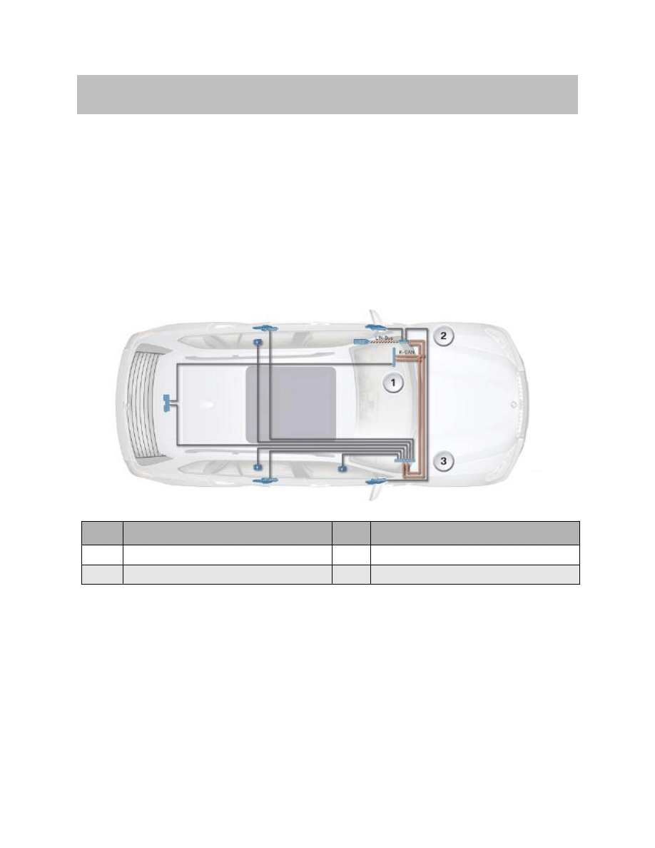
The following graphic shows all the components of the power window system together
with the respective control units and control elements.
The following components are described:
• Control elements
• Control units
– Car Access System 3
– Footwell module
– Junction box control unit
• Power window motor
System Components
Index
Explanation
Index
Explanation
1
Car Access System 3
3
Junction box control unit
2
Footwell module
8
E70 Power Windows
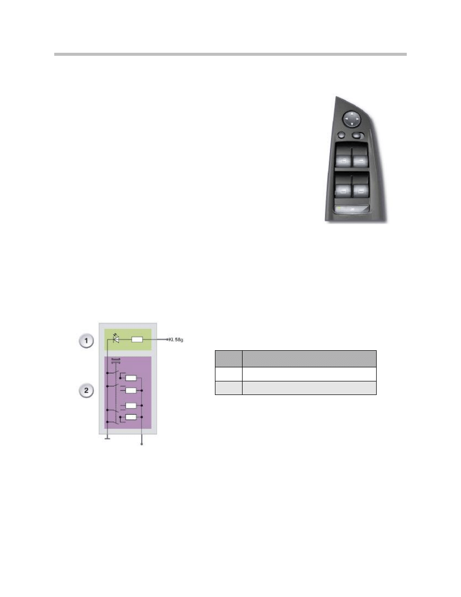
Control Elements
Driver's Door Switch Cluster
The driver's door switch cluster is connected via the LIN
bus to the footwell module.
For opening or closing, the power window switch has two
notch positions. The first notch position is used for the
manual power window function. The second notch posi-
tion (press) is used for the toll function of the power win-
dows.
The power window switches are resistance coded and
switched to earth. The following graphic shows the princi-
ple of a resistance coded switch.
Window Switch Signal Evaluation
The signals of the power window switch in the driver's door switch console are
evaluated directly by the driver's door switch cluster and transferred to the footwell
module via the LIN bus.
The signals from the power window switches in the front passenger's door as well as the
power window switches of the both rear doors are evaluated by the junction box control
unit.
Index
Explanation
1
Illumination of power window switch
2
Resistance-coded switch

9
E70 Power Windows
Control Units
Car Access System 3
The Car Access System 3 is the central control unit for opening and closing the windows.
Therefore, it issues the enable to operate the power windows During the engine start
phase, it is not possible to move the power windows. This means more energy from the
battery is available for the starter during engine start-up.
Footwell Module
The relays for the power window motors for the front doors are installed in the footwell
module.
The footwell module provides information on the status of the door contacts and the dri-
ver's door lock cylinder.
The footwell module also provides the power window switch and the driver's door switch
console with information on the "Terminal 58g ON" status.
Junction Box Control Unit
The relays for the power window motors for the rear doors are installed in the junction box
control unit.
Remote Control
The remote control can initiate the comfort opening/comfort closing procedure for the
power windows.
Note: The ID transmitter can also perform the functions of the remote control.
The comfort opening and closing function with the ID transmitter is
therefore the same as with the remote control.
Power Window Motors
The power window motors are equipped with Hall sensors that generate signals during
motor operation. These signals serve the purpose of monitoring motor operation and are
evaluated for the anti-trap mechanism.
The signals are evaluated in the footwell module and the junction box control unit.

10
E70 Power Windows
The functions of the power windows on the E70 are:
• Opening and closing
• Opening and closing with toll function
• Comfort opening and closing
• Indirect anti-trap mechanism
• Panic mode
• Load shut-down at terminal 50
• Thermal protection of power window motors
Opening and closing
The Car Access System 3 has the central control function for electric opening and
closing of the power windows.
This means that the Car Access System 3 issues the enable to open and close the
power windows. The footwell module and the junction box control unit actuate the
power window motors and monitor the motor speed of the respective power window
motor. This means the footwell module or the junction box control unit can respond to
the following operating situations:
• Trapping
• Overheating of the power window motor
• Seizing of the power window motor.
Opening and Closing
The corresponding power window motor is activated in OPEN or CLOSE direction by
pressing or pulling the power window switches to the first notch position. The power
window motor remains active until the corresponding power window switch is released.
To ensure the power window is closed securely, the power window motor is briefly dri-
ven to block status at the limit stop.
Toll Function
The toll function is implemented for all power windows. The corresponding power win-
dow motor is driven in the OPEN or CLOSE direction by pressing or pulling a power win-
dow switch beyond the limit stop.
The power window motor moves the window automatically until it is completely open or
closed. Power window operation is stopped when the power window switch is pressed
or pulled again.
Principles of Operation
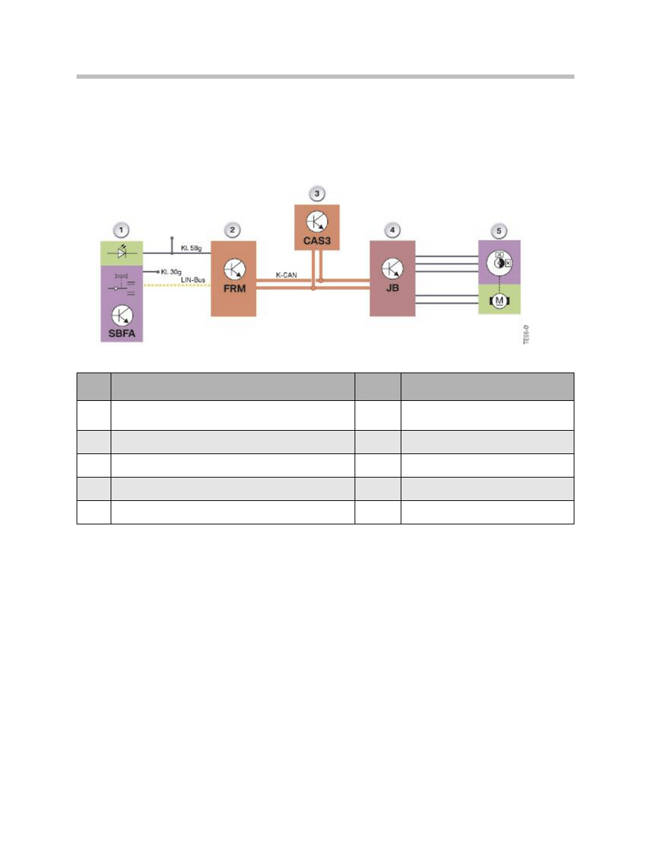
By way of example, the opening and closing procedure for one of the rear windows is
illustrated by the signal path in the following graphic. The opening or closing function is
initiated from the driver's door switch cluster.
11
E70 Power Windows
Inde
x
Explanation
Index
Explanation
1
SBFA power window switch
in driver's door switch cluster
LIN-bus
LIN bus
2
FRM footwell module
K-CAN
Body CAN
3
Car Access System 3 CAS 3
KL. 30g
Terminal 30g
4
JB junction box control unit
KL. 58g
Terminal 58g
5
Power window motor
Example: Opening or closing the rear window in the E70

12
E70 Power Windows
Comfort Opening and Closing
Comfort opening or closing can be performed with the remote control/ID transmitter via
the door lock in the driver's door or the outside driver's/passenger's door handle.
Comfort opening with remote control The comfort opening function is initiated by unlock-
ing the vehicle with the remote control and keeping the button pressed for longer than 5
seconds.
Initially, the front windows are opened, followed after a short time delay by the rear win-
dows and the panorama glass roof.
The signal from the remote control is picked up by the Car Access System 3 via the
remote control receiver.
The Car Access System 3 issues the enable to operate the power windows and initiates
the comfort opening function. The footwell module and the junction box control unit cor-
respondingly activate the power window motors.
With Remote Control
The comfort closing function is initiated after locking the vehicle with the remote control
and keeping the button pressed for longer than 5 seconds. Initially, the panorama glass
roof is closed followed after a short time delay by the rear/front windows.
If the folding exterior mirrors option is installed, the mirrors are folded in simultaneously as
the rear windows are closed.
Via the Driver's Door Lock Barrel
There are two Hall sensors installed in the door lock for the purpose of opening and clos-
ing the vehicle. The Hall sensors enable the footwell module to detect the position of the
mechanical key or of the spare key in the lock barrel.
The key must be turned to the open or close position to initiate the comfort opening and
closing function. The comfort opening or closing function is initiated when the key is held
in this position.
The footwell module sends the request via the K-CAN. On conclusion of the correspond-
ing check, the Car Access System 3 initiates the comfort opening or closing procedure.
With Comfort Access
In connection with Comfort Access, the comfort closing function is triggered via the dri-
ver's/passenger's outside door handle.
It is sufficient to touch the sensitive area of the outside door handle in order to trigger the
comfort closing function via the door handle.
Comfort closing is triggered if the sensitive area is touched for longer than 5 seconds.
The ID transmitter must be within an approximately 2 m radius of the vehicle.

13
E70 Power Windows
Anti-Trap Mechanism
Essentially, the indirect anti-trap mechanism does not prevent an object being trapped
but rather it limits the trapping force to maximum 80 N. The power window motor is
reversed on exceeding this trapping force.
The footwell module and the junction box control unit monitor the activated power win-
dow motors. The indirect anti-trap mechanism for the front windows is activated by the
footwell module. The indirect anti-trap mechanism for the rear windows is activated by
the junction box control unit.
The indirect anti-trap mechanism in the E90 is based on the evaluation of the Hall pulses
from the power window motors. The speed is derived from the Hall pulses of the power
window motors. Speed fluctuations within certain ranges trigger the indirect anti-trap
mechanism so that the windows are opened.
Operation of the power window switches is ineffective while the windows are in the
process of opening.
If no operable anti-trap mechanism is detected as the result of defective Hall sensors, the
window can only be operated in jolts. The power window is in emergency mode and
must be reinitialized. A Check Control message will be displayed.
Panic Mode
Panic mode is triggered by overpulling - releasing- overpulling (overpulling = pulling
beyond limit stop) the power window switches.
It is necessary to release and overpull the switch again as the anti-trap mechanism is still
active the first time the switch is overpulled.
Overpulling the power window switch the second time within 4 seconds closes the win-
dow with maximum force.
Note: The indirect anti-trap mechanism is no longer active in this case. The
window closes at the maximum closing force and does not reverse.

14
E70 Power Windows
Load Shut-Down, Terminal 50
To protect the battery, operation of the power windows is interrupted during the vehicle
start procedure.
The Car Access System 3 revokes the enable for power window operation in order to
interrupt current operation of the power windows. The signal is received by the footwell
module and junction box control unit via the K-CAN.
The power window switches must be pressed again following an interruption in opera-
tion. The corresponding function is not executed if the power windows are operated dur-
ing the start procedure.
The enable for operation of the power windows is not issued until the start procedure has
been completed.
Thermal Protection
The footwell module and the junction box control unit monitor the motor temperature.
The motor temperature is determined based on the outside temperature, motor running
time and the time the motor is stationary (not operative).
Each motor can be switched off individually to prevent the power window motors over-
heating during operation of the power windows). The motor is then deactivated for a
defined period of time. The thermal protection facility does not prevent the windows
being opened in the case of trapping. Once started, a power window function is not inter-
rupted by the thermal protection facility.
In panic mode the window can still be closed even when the thermal protection function
is active.

15
E70 Power Windows
Initialization
The front and rear power windows can be initialized via the power window switches or
the BMW diagnosis system.
Via Window Switches
The following procedure must be performed to initialize the system:
• Completely close window by pulling the power window switch beyond the limit
stop.
• Briefly interrupt pulling the power window switch and then pull the switch upwards
again for approximately. 1 second.
Via the BMW Diagnosis Equipment
The power windows can be initialized as part of an initialization job using the diagnosis
system. A detailed description of the initialization procedure is provided in the BMW
diagnosis system.
Note: The power windows can only be moved in jolts if not initialized.
Service Information
Document Outline
- Main Menu
- E70 Introduction
- E70 Glovebox
- E70 Powertrain
- E70 Gasoline Engines
- E70 Transmissions
- E70 Voltage Supply and Bus Systems
- E70 Car Access System 3
- E70 Energy Management
- E70 Chassis Dynamics
- E70 Lateral Dynamics Systems
- E70 Vertical Dynamics Systems
- E70 Longitudinal Dynamics Systems
- E70 Central Locking
- E70 Power Windows
- E70 Comfort Access
- E70 Wipe/Wash System
- E70 Panorama Glass Sunroof
- E70 Seats
- E70 Automatic Tailgate
- E70 Steering Column Switch Cluster
- E70 Exterior Lighting
- E70 Interior Lighting
- E70 Adaptive Headlight System
- E70 Park Distance Control
- E70 Rear-view Camera
- E70 Anti-Theft Alarm System
- E70 Outside Mirrors
- E70 Displays Indicators and Controls
- E70 Head-up Display
- E70 Information and Communication
- E70 Audio Systems
- E70 Rear Seat Entertainment
- E70 Climate Control Systems
- E70 Passive Safety Systems
Wyszukiwarka
Podobne podstrony:
Popular Mechanics Repairing Power Windows
Power Window
Power Window Circuit (1 of 2)
05 4 F01 Power Windows
power windows
96ZJ 8S POWER WINDOW SYSTEMS
Power Window Circuit (2 of 2)
power windows
POWER WINDOWS CONTROL
BMW E38 schematic Power windows
93ZJ Secc 8S Power Windows
get windows product key power shell
Software Power Off on Windows NT 4 0
6623 Getting started with the Power BI mobile app for Windows 10 WSG 2
Windows 8 1 Power User Guide
Instalacja Windows XP power point
07 Windows
więcej podobnych podstron