
POWER WINDOWS
1993 Mitsubishi Montero
1993 ACCESSORIES & EQUIPMENT
Mitsubishi Power Windows
Montero
DESCRIPTION & OPERATION
With the ignition switch in RUN position, battery voltage is
applied to the master power window switch located on the driver’s
door. The master power window switch provides power and ground for all
power window switches and motors. The master power window switch
offers one-touch operation of driver’s window. A solid state control
unit, incorporated in the master switch, fully lowers driver’s window
when switch is completely depressed. Master switch also includes lock-
out feature to prevent passengers from operating any of the other
power window door switches.
TROUBLE SHOOTING
POWER WINDOWS INOPERATIVE
Check for faulty sub fusible link No. 10, faulty power window
relay or faulty power window switches.
ONE WINDOW FAILS TO OPERATE
If one window does not operate, even if both master and
passenger side power window switches are pressed, check for faulty
master power window switch or power window motor that is inoperative.
If one window does not operate, only when either master or passenger
side power window switch is pressed, but does operate when both
switches are pressed, check power window switch that is inoperative.
ONE-TOUCH SWITCH FUNCTION INOPERATIVE
Replace master power window switch.
TESTING
CIRCUIT BREAKER TEST
Press UP switch to fully close window. Continue to press
switch for 10 seconds. Release UP switch and immediately press DOWN
switch. If window begins to open within 60 seconds, circuit breaker is
okay. Circuit breaker is part of window motor.
POWER WINDOW RELAY TEST
1) Remove power window relay from fuse/relay block, located
in engine compartment. See Fig. 1. Check continuity between power
window relay terminals No. 2 and No. 4. Continuity should be present.
2) Connect positive lead of a 12-volt battery to power window
relay terminal No. 2, and negative lead of test battery to terminal
No. 4. See Fig. 2. Continuity should be present between terminals No.
1 and No. 3 with voltage applied. Replace power window relay if
continuity is not as specified.
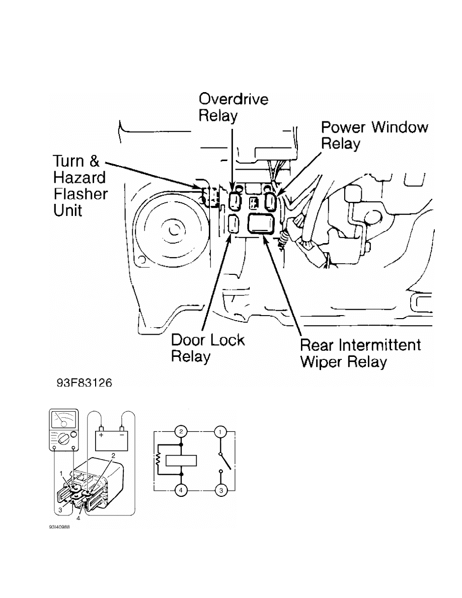
Fig. 1: Locating Power Window Relay
Courtesy of Mitsubishi Motor Sales of America.
Fig. 2: Power Window Relay Terminal ID
Courtesy of Mitsubishi Motor Sales of America.
POWER WINDOW MOTOR TEST

1) Remove appropriate door trim panel. Connect positive lead
of a 12-volt test battery to either motor terminal. Connect negative
lead of test battery to other motor terminal. Motor should operate,
unless it is already at maximum travel.
2) Reverse test battery leads. Motor should operate in
opposite direction. If motor does not operate, inspect wiring. If
wiring is okay, replace motor. Reverse test battery leads again to
complete full function test of motor.
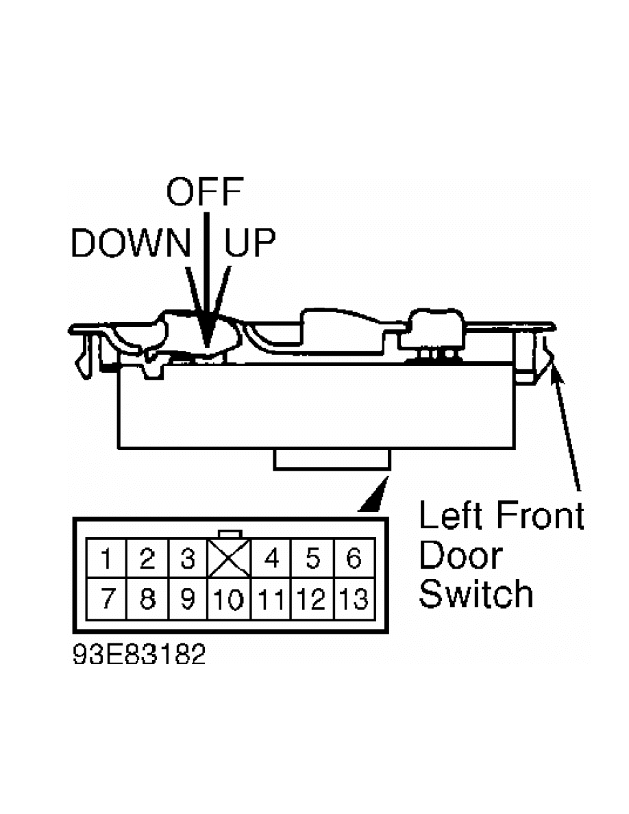
POWER WINDOW SWITCH TEST
Remove control switch from trim panel. Using ohmmeter, check
continuity of switch. See appropriate WINDOW SWITCH CONTINUITY CHART.
See Figs. 3-5. Replace appropriate switch as necessary if switch
continuity is not as specified.
MASTER WINDOW SWITCH CONTINUITY CHART
Switch Position (1) Check Continuity Between
Normal Position
Left Front OFF .......................... Pins 2, 8 & 13
Left Rear OFF .......................... Pins 4, 11 & 13
Left Front UP .................. Pins 2 & 9; Pins 8 & 13
Left Rear UP ....................... Pins 4 & 9; 11 & 13
Left Front DOWN ................ Pins 2 & 13; Pins 8 & 9
Left Rear DOWN ................ Pins 4 & 13; Pins 9 & 11
Right Front OFF ......................... Pins 1, 7 & 13
Right Rear OFF ......................... Pins 5, 12 & 13
Right Front UP ................. Pins 1 & 9; Pins 7 & 13
Right Rear UP ................. Pins 5 & 9; Pins 12 & 13
Right Front DOWN ............... Pins 1 & 13; Pins 7 & 9
Right Rear DOWN ............... Pins 5 & 13; Pins 9 & 12
Lock Position
Left Front OFF .......................... Pins 2, 8 & 13
Left Rear OFF .............................. Pins 4 & 11
Left Front UP .................. Pins 2 & 9; Pins 8 & 13
Left Rear UP ................................ Pins 4 & 9
Left Front DOWN ................ Pins 2 & 13; Pins 8 & 9
Left Rear DOWN ............................. Pins 9 & 11
Right Front OFF ............................. Pins 1 & 7
Right Rear OFF ............................. Pins 5 & 12
Right Front UP .............................. Pins 1 & 9
Right Rear UP ............................... Pins 5 & 9
Right Front DOWN ............................ Pins 7 & 9
Right Rear DOWN ............................ Pins 9 & 12
(1) - Left side of vehicle refers to driver’s side.
RIGHT FRONT SIDE WINDOW SWITCH CONTINUITY CHART
Switch Position Check Continuity Between
OFF ............................... Pins 1 & 7; Pins 2 & 5
UP ................................ Pins 2 & 5; Pins 6 & 7
DOWN .............................. Pins 1 & 7; Pins 5 & 6
REAR DOOR SIDE WINDOW SWITCH CONTINUITY CHART
Switch Position Check Continuity Between
OFF ............................... Pins 1 & 2; Pins 3 & 5
UP ................................ Pins 1 & 2; Pins 3 & 4
DOWN .............................. Pins 2 & 4; Pins 3 & 5
Fig. 3: Driver’s Power Window Switch Connector Terminal ID
Courtesy of Mitsubishi Motor Sales of America.
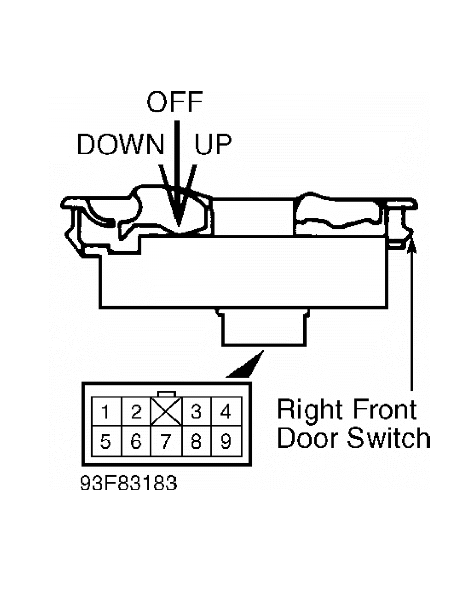
Fig. 4: Right Front Power Window Switch Connector Terminal ID
Courtesy of Mitsubishi Motor Sales of America.
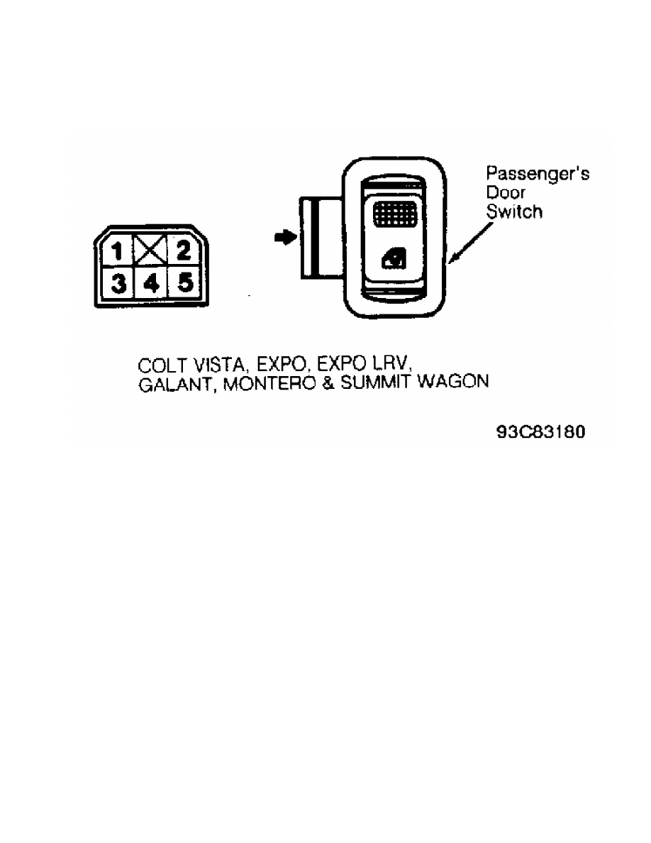
Fig. 5: Rear Door Power Window Switch Connector Terminal ID
Courtesy of Mitsubishi Motor Sales of America.
REMOVAL & INSTALLATION
POWER WINDOW MOTOR
Removal & Installation
Remove door trim panel and waterproof shield. Remove glass
retaining screws and glass. See Fig. 6. Remove motor and slider
assembly retaining bolts and remove motor and slider assembly from
door. To install, reverse removal procedure.
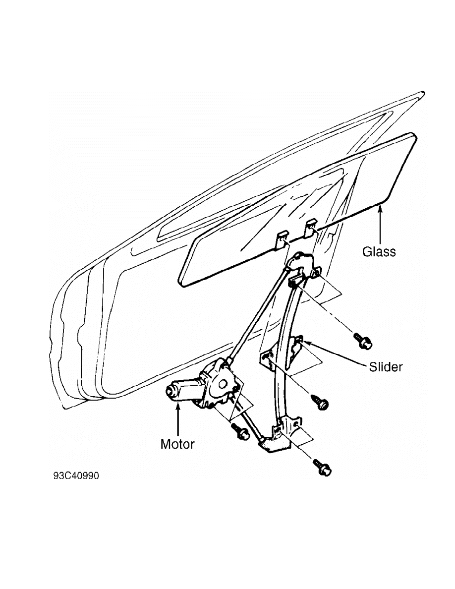
Fig. 6: Removing Power Window Motor & Slider Assembly
Courtesy of Mitsubishi Motor Sales of America.
WIRING DIAGRAMS
See appropriate chassis wiring diagram in the WIRING DIAGRAMS
section.
Wyszukiwarka
Podobne podstrony:
Popular Mechanics Repairing Power Windows
Power Window
Power Window Circuit (1 of 2)
05 4 F01 Power Windows
power windows
96ZJ 8S POWER WINDOW SYSTEMS
05a2 E70 Power Windows
Power Window Circuit (2 of 2)
POWER WINDOWS CONTROL
BMW E38 schematic Power windows
93ZJ Secc 8S Power Windows
get windows product key power shell
Software Power Off on Windows NT 4 0
6623 Getting started with the Power BI mobile app for Windows 10 WSG 2
Windows 8 1 Power User Guide
Instalacja Windows XP power point
07 Windows
więcej podobnych podstron