
CL03Y-02
-
CLUTCH
TROUBLESHOOTING
CL-1
1542
Author:
Date:
1997 SUPRA (RM502U)
TROUBLESHOOTING
PROBLEM SYMPTOMS TABLE
Use the table below to help you find the cause of the problem. The numbers indicate the priority of the likely
cause of the problem. Check each part in order. If necessary, replace these parts.
Symptom
Suspect Area
See page
Clutch grabs/chatters
1. Engine mounting (Loosen)
2. Clutch disc (Runout is excessive)
3. Clutch disc (Oily)
4. Clutch disc (Worn out)
5. Clutch disc (Damaged torsion rubber)
6. Clutch disc (Glazed)
7. Diaphragm spring (Out of tip alignment)
-
Clutch pedal spongy
1. Clutch line (Air in line)
2. Master cylinder cup (Damaged)
3. Release cylinder cup (Damaged)
-
Clutch noisy
1. Release bearing (Worn, dirty or damaged)
2. Pilot bearing (Worn or damaged)
3. Input shaft bearing (Worn, dirty or damaged)
4. Clutch disc torsion rubber (Damaged)
-

CL-2
-
CLUTCH
TROUBLESHOOTING
1543
Author:
Date:
1997 SUPRA (RM502U)
Clutch slips
1. Clutch pedal (Freeplay out of adjustment)
2. Clutch disc (Oily)
3. Clutch disc (Worn out)
4. Diaphragm spring (Damaged)
5. Pressure plate (Distortion)
6. Flywheel (Distortion)
-
Clutch does not disengage
1. Clutch pedal (Freeplay out of adjustment)
2. Clutch line (Air in line)
3. Master cylinder cup (Damaged)
4. Release cylinder cup (Damaged)
5. Input shaft bearing (Worn, dirty or damaged)
6. Pilot bearing (Worn or damaged)
7. Clutch disc (Out of true)
8. Clutch disc (Runout is excessive)
9. Clutch disc (Lining broken)
10. Clutch disc (Dirty or burred)
11. Clutch disc (Oily)
12. Clutch disc (Lack of spline grease)
13. Diaphragm spring (Damaged)
14. Diaphragm spring (Out of tip alignment)
15. Pressure plate (Distortion)
-
-
CL045-02
CL-10
-
CLUTCH
CLUTCH RELEASE CYLINDER
1551
Author:
Date:
1997 SUPRA (RM502U)
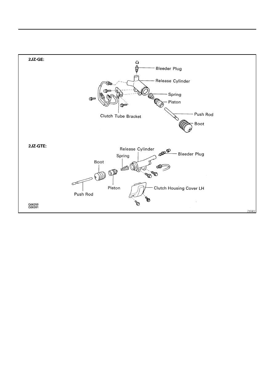
CLUTCH RELEASE CYLINDER
COMPONENTS
CL0AB-01
Q01125
Q01126
-
CLUTCH
CLUTCH RELEASE CYLINDER
CL-1 1
1552
Author:
Date:
1997 SUPRA (RM502U)
REMOVAL
1.
2JZ - GTE:
REMOVE CLUTCH HOUSING COVER LH
Remove the 2 bolts.
Torque: 12 N·m (120 kgf·cm, 9 ft·lbf)
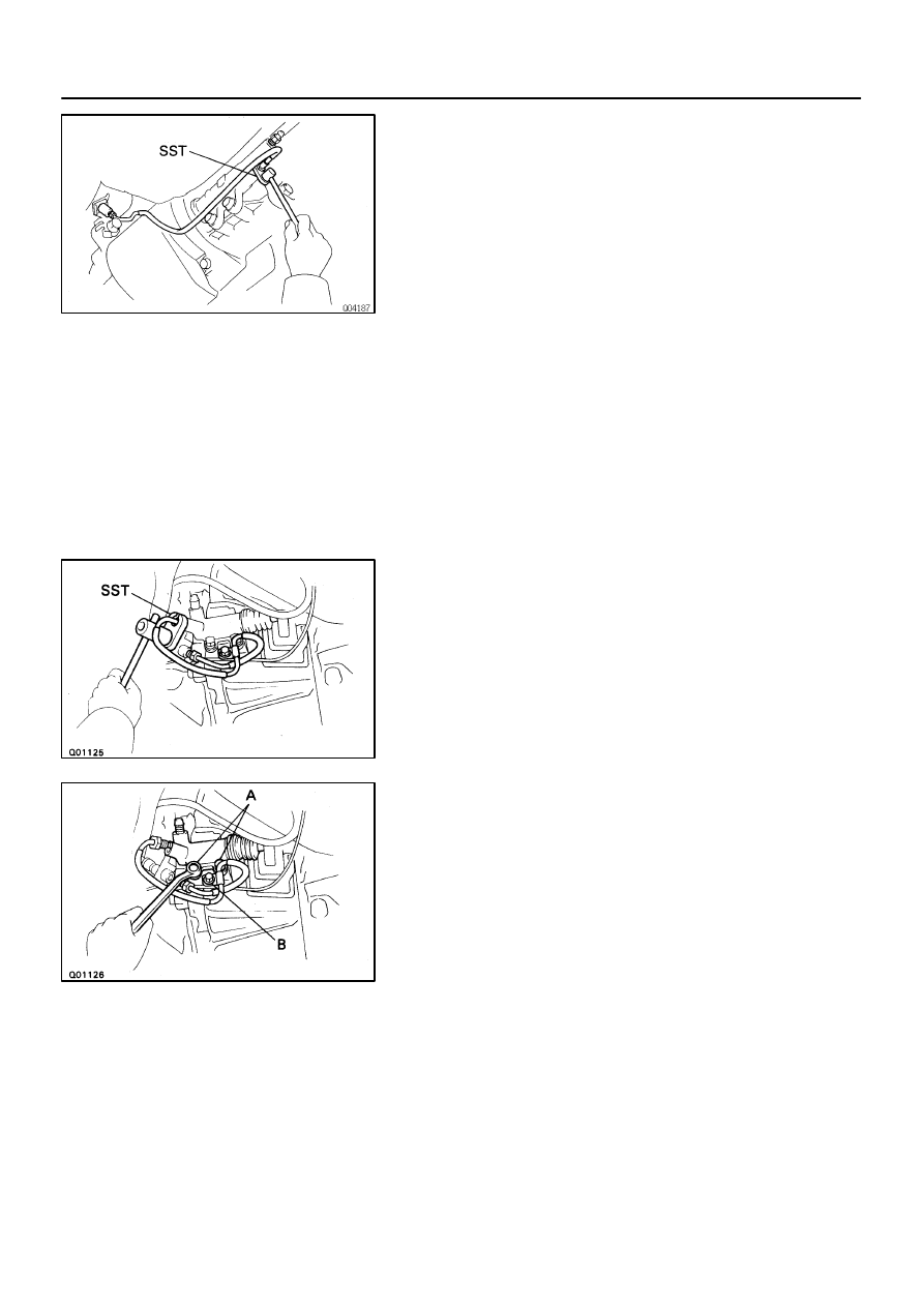
2.
2JZ - GTE:
DISCONNECT CLUTCH LINE
Using SST, disconnect the clutch line union. Use a container to
catch the fluid.
SST
09023-00100
Torque: 15 N·m (155 kgf·cm, 11 ft·lbf)
3.
2JZ - GTE:
REMOVE 2 BOLTS AND PULL OUT RELEASE CYL-
INDER
Torque: 12 N·m (120 kgf·cm, 9 ft·lbf)
4.
2JZ - GE:
DISCONNECT CLUTCH LINE
Using SST, disconnect the clutch line union. Use a container to
catch the fluid.
SST
09023-00100
Torque: 15 N·m (155 kgf·cm, 11 ft·lbf)
5.
2JZ - GE:
REMOVE RELEASE CYLINDER WITH 3 BOLTS
Torque:
Bolt A: 12 N·m (120 kgf·cm, 9 ft·lbf)
Bolt B: 4.9 N·m (50 kgf·cm, 43 in.·lbf)
CL047-01
Q04338
CL-12
-
CLUTCH
CLUTCH RELEASE CYLINDER
1553
Author:
Date:
1997 SUPRA (RM502U)
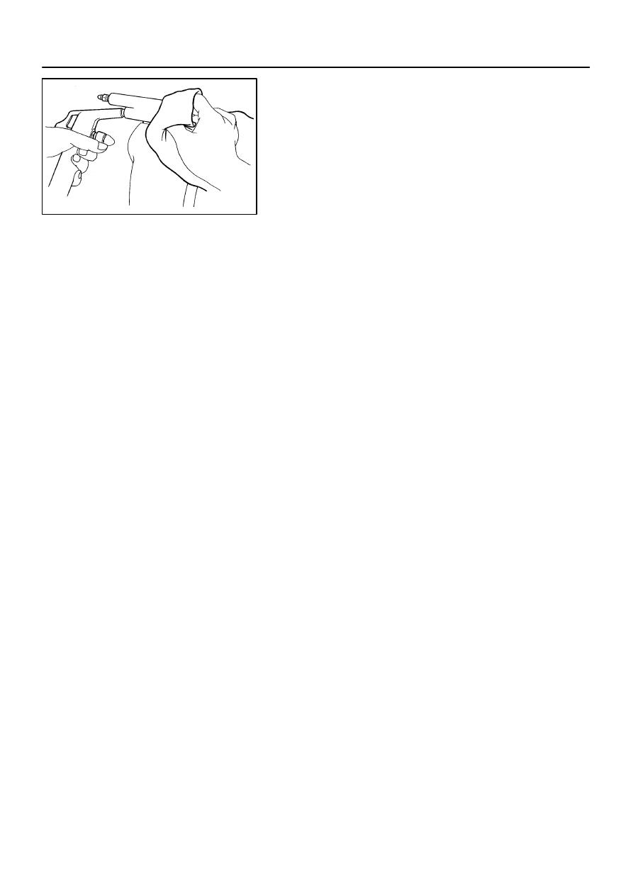
DISASSEMBLY
1.
PULL OUT PUSH ROD WITH BOOT
2.
REMOVE PISTON WITH SPRING
Using compressed air, remove the piston and spring from the
cylinder.
CL048-01
Z07291
-
CLUTCH
CLUTCH RELEASE CYLINDER
CL-13
1554
Author:
Date:
1997 SUPRA (RM502U)
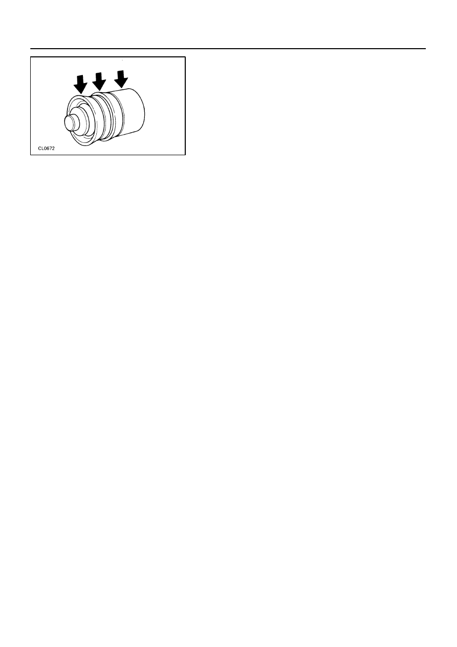
REASSEMBLY
1.
COAT PISTON WITH LITHIUM SOAP BASE GLYCOL
GREASE, AS SHOWN
2.
INSTALL PISTON WITH SPRING INTO CYLINDER
3.
INSTALL BOOT WITH PUSH ROD TO CYLINDER
CL04A-03
Q06260
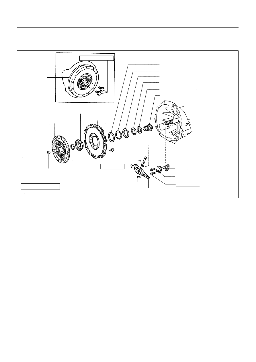
Plate Washer
Wave Washer
Snap Ring
Clutch Thrust Cone Spring
Clutch Release Hub
Release Fork Support
Clutch Disc
Clutch Release Bearing
Plate Washer
Release Fork Support Spring
E-Ring
Release Fork
x9
Pilot Bearing
Clutch Cover
Snap Ring
Wave
Washer
Flywheel
Assembly
25 (260, 18)
19 (195, 14)
N·m (kgf·cm, ft·lbf) : Specified torque
Non-reusable part
Pin
CL-20
-
CLUTCH
CLUTCH UNIT (2JZ-GTE)
1561
Author:
Date:
1997 SUPRA (RM502U)
CLUTCH UNIT (2JZ-GTE)
COMPONENTS
CL04B-02
Q04195
Q04196
Q04197
Q04198
-
CLUTCH
CLUTCH UNIT (2JZ-GTE)
CL-21
1562
Author:
Date:
1997 SUPRA (RM502U)
REMOVAL
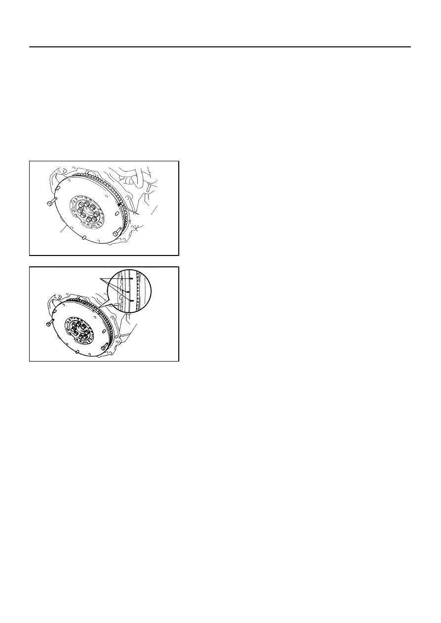
1.
REMOVE TRANSMISSION FROM ENGINE
(See page MT-2)
HINT:
Do not drain the transmission oil.
2.
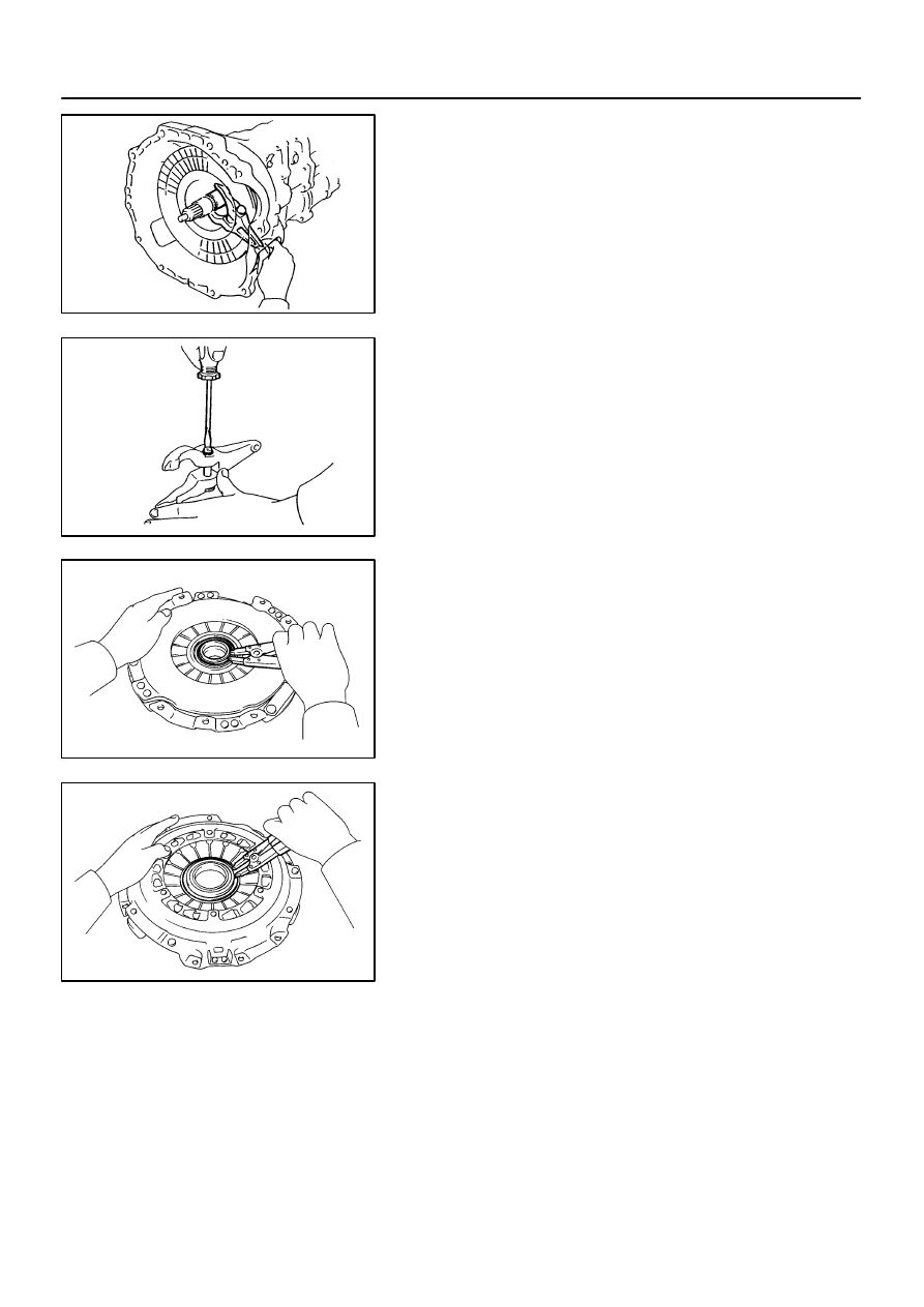
REMOVE RELEASE FORK ASSEMBLY
(a)
Remove the release fork assembly from the left side of
clutch housing service hole.
(b)
Remove the E-ring from the release fork.
(c)
Remove the pin and wave washer from the release fork.
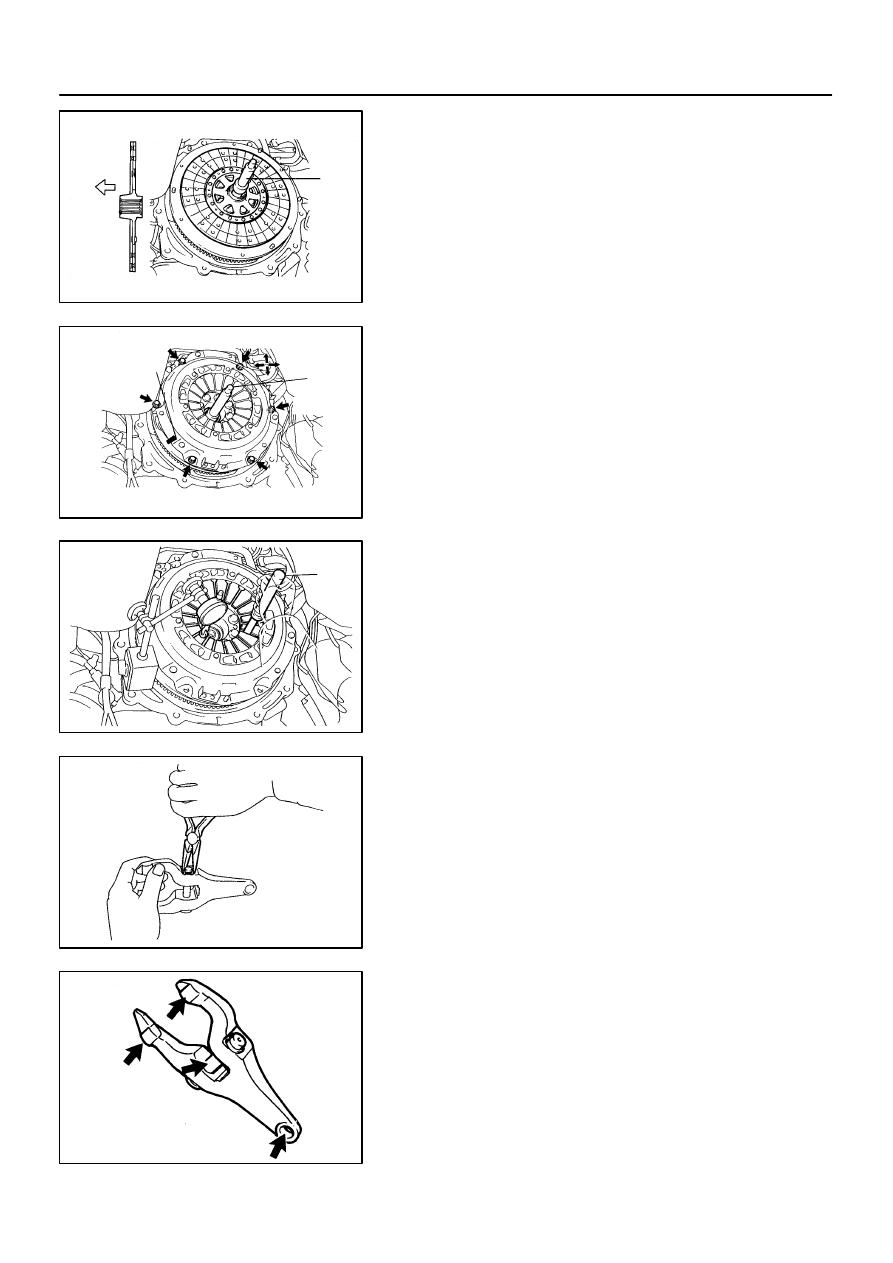
3.
REMOVE CLUTCH DISC
4.
REMOVE CLUTCH COVER ASSEMBLY
5.
REMOVE CLUTCH RELEASE BEARING HUB
(a)
Using a snap ring expander, remove the snap ring.
(b)
Remove the release bearing hub, thrust cone spring and
plate washer.
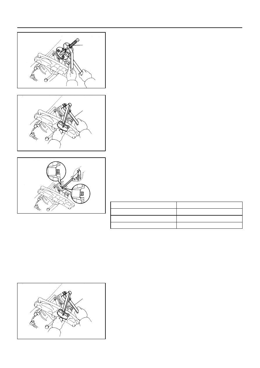
6.
REMOVE CLUTCH RELEASE BEARING
(a)
Using a snap ring expander, remove the snap ring.
(b)
Remove the release bearing, wave washer and plate
washer.
CL04C-02
Q04200
Q04201
Q04202
Q04204
Q04206
CL-22
-
CLUTCH
CLUTCH UNIT (2JZ-GTE)
1563
Author:
Date:
1997 SUPRA (RM502U)
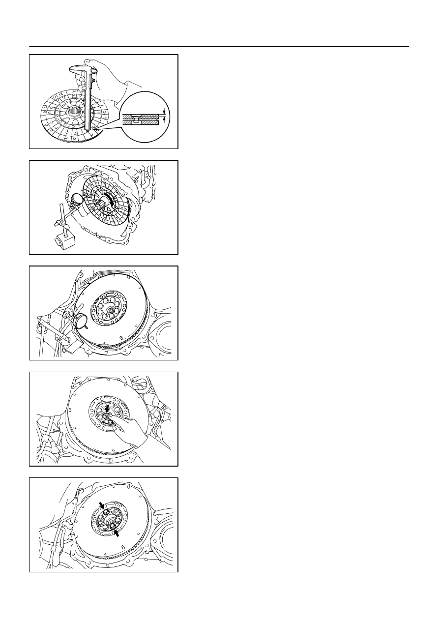
INSPECTION
1.
INSPECT CLUTCH DISC FOR WEAR OR DAMAGE
Using calipers, measure the rivet head depth.
Maximum rivet depth: 0.3 mm (0.012 in.)
If necessary, replace the clutch disc.
2.
INSPECT CLUTCH DISC RUNOUT
Using a dial indicator, check the disc runout.
Maximum runout: 0.8 mm (0.031 in.)
If the runout is excessive, replace the clutch disc.
3.
INSPECT FLYWHEEL RUNOUT
Using a dial indicator, check the flywheel runout.
Maximum runout: 0.1 mm (0.004 in.)
If the runout is excessive, replace the flywheel.
4.
INSPECT PILOT BEARING
Turn the bearing by hand while applying force in the axial direc-
tion.
If the bearing sticks or has much resistance, replace the pilot
bearing.
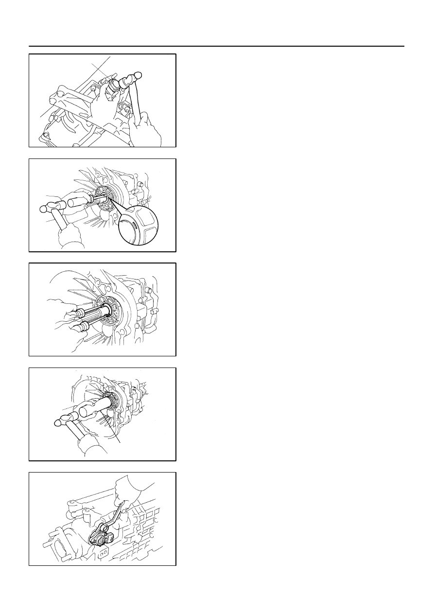
5.
IF NECESSARY, REPLACE PILOT BEARING
(a)
Remove the 2 bolts at the diametrically opposite points.
Q04207
SST
Q04208
SST
Q04206
Q04203
B
A
Q04223
-
CLUTCH
CLUTCH UNIT (2JZ-GTE)
CL-23
1564
Author:
Date:
1997 SUPRA (RM502U)
(b)
Using SST, remove the pilot bearing.
SST
09303-3501 1
(c)
Using SST and a hammer, drive in a new pilot bearing.
SST
09301-001 10
(d)
Install 2 new bolts.
(e)
First, torque the 2 bolts uniformly a little at a time.
Torque: 49 N·m (500 kgf·cm, 36 ft·lbf)
(f)
Then tighten the 2 bolts an additional 80 - 100
°
.
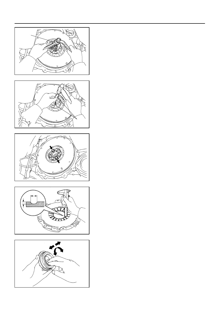
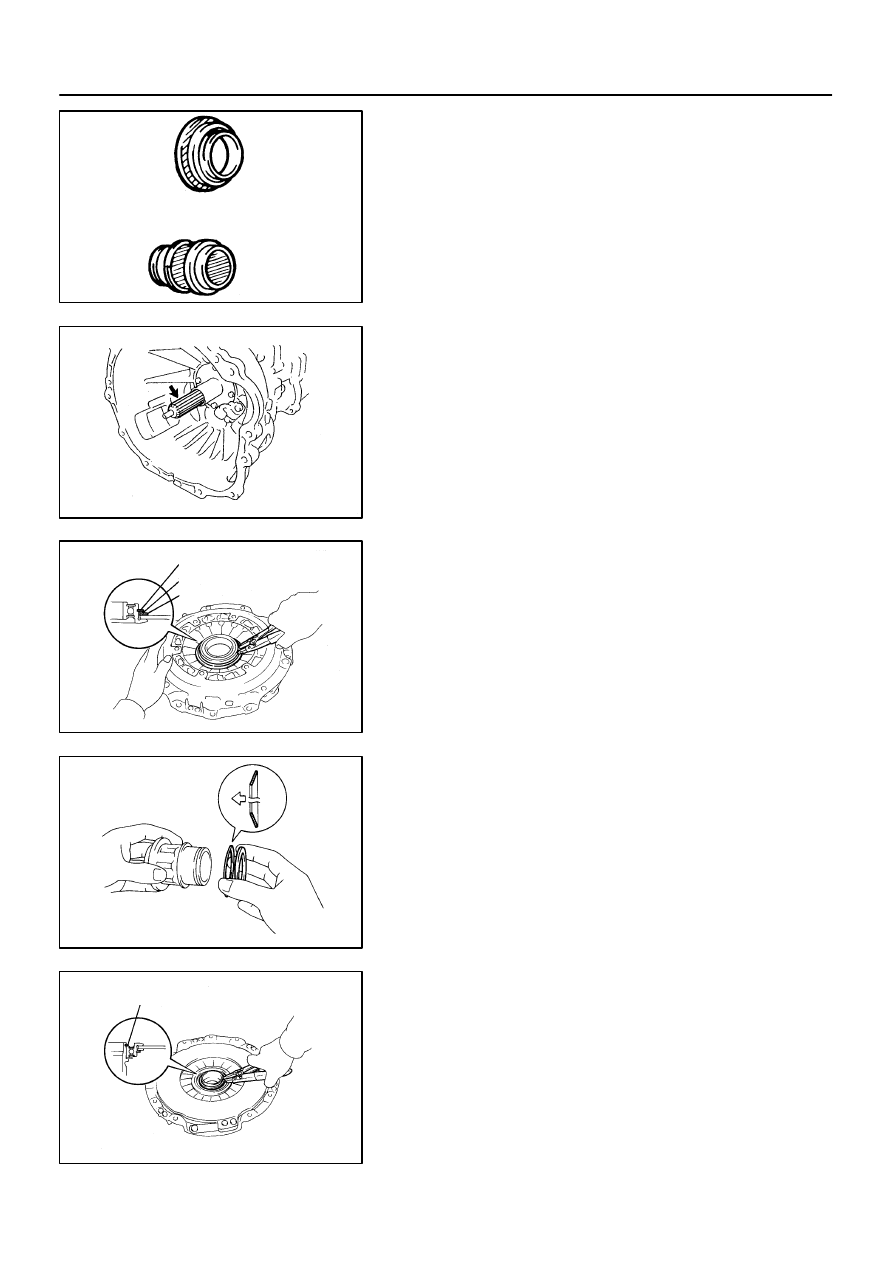
6.
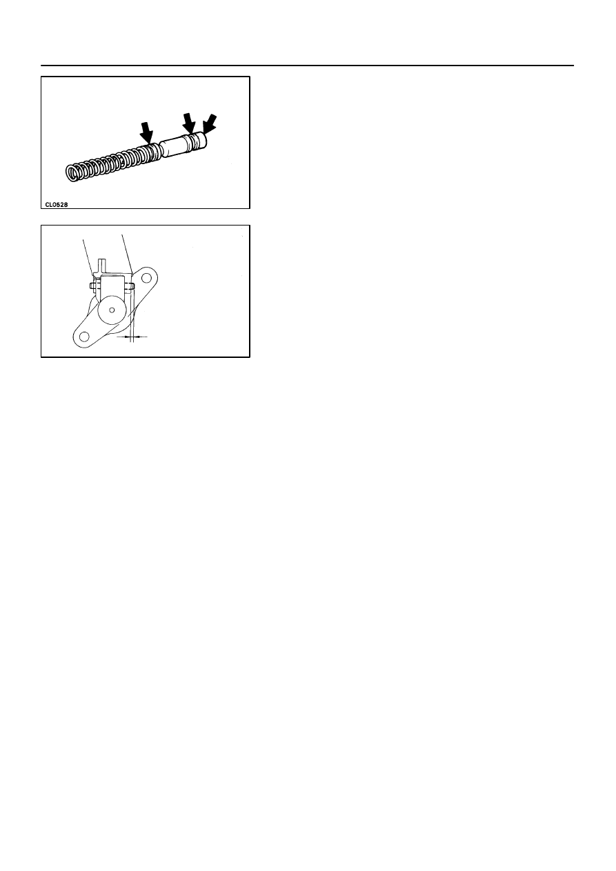
INSPECT DIAPHRAGM SPRING FOR WEAR
Using calipers, measure the diaphragm spring for depth and
width of wear.
Maximum:
Depth A: 0.6 mm (0.024 in.)
Width B: 5.0 mm (0.197 in.)
If necessary, replace the clutch cover.
7.
INSPECT RELEASE BEARING
Turn the bearing by hand while applying force in the axial direc-
tion.
HINT:
The bearing is permanently lubricated and requires no cleaning
or lubrication.
If a problem is found, replace the bearing together with the hub.
Q04326
Matchmarks
Secondary
Flywheel
Primary
Flywheel
Q04327
Matchmarks
CL-24
-
CLUTCH
CLUTCH UNIT (2JZ-GTE)
1565
Author:
Date:
1997 SUPRA (RM502U)
8.
INSPECT FLYWHEEL DAMPER FOR GREASE LEAK-
AGE
If grease has sprayed onto the clutch housing, replace the fly-
wheel assembly.
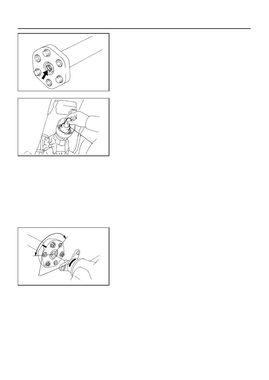
9.
INSPECT FLYWHEEL DAMPER ROTATIONAL FREE-
PLAY
(a)
Install the 2 bolts to the secondary flywheel at diametrical-
ly opposite positions.
(b)
Holding both the bolts, and turn the secondary flywheel
clockwise until it stops.
(c)
Put matchmarks on the primary and secondary flywheels
at this position.
(d)
Then rotate the primary flywheel counterclockwise by
hand until it stops.
(e)
Put matchmarks on the primary flywheel at this position.
(f)
Measure the circumferential length between the 2 match-
marks on the secondary flywheel.
Standard: 105 mm (4.134 in.)
(g)
Repeat the previous steps (d) to (f) 4 times and if the mea-
surement is greater than the maximum length replace the
flywheel assembly (See page
).
CL04D-01
Z13786
SST
Front
Q04210
SST
7
3
1, 4
2, 5
8
6
Matchmarks
Q06263
SST
Q04219
Q04403
-
CLUTCH
CLUTCH UNIT (2JZ-GTE)
CL-25
1566
Author:
Date:
1997 SUPRA (RM502U)
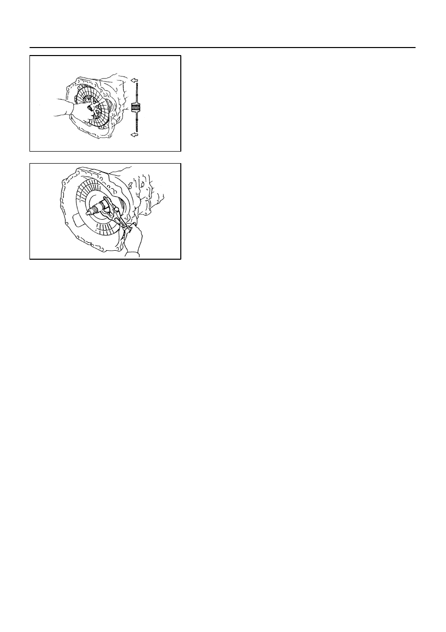
INSTALLATION
1.
INSTALL CLUTCH DISC AND COVER ON FLYWHEEL
(a)
Insert SST in the clutch disc, then set them and the cover
in position.
SST
09301-001 10
(b)
Align the matchmarks on the clutch cover and flywheel.
(c)
Tighten the bolts evenly and gradually while pushing the
SST. Make several passes around the cover until it is
snug.
(d)
Torque the bolts on the clutch cover in the order shown.
Torque: 19 N·m (195 kgf·cm, 14 ft·lbf)
HINT:
Temporarily tighten the No.1 and No.2 bolts.
2.
CHECK DIAPHRAGM SPRING TIP ALIGNMENT
Using a dial indicator with roller instrument, check the dia-
phragm spring tip alignment.
Maximum non-alignment: 0.5 mm (0.020 in.)
If the alignment is not as specified, use SST to adjust the dia-
phragm spring tip alignment.
SST
09333-00013
3.
REMOVE CLUTCH COVER AND CLUTCH DISC
4.
INSTALL CLUTCH RELEASE FORK
(a)
Install the wave washer and pin to release fork.
(b)
Install a new E-ring.
5.
APPLY MOLYBDENUM DISULPHIDE LITHIUM BASE
GREASE (NLGI NO.2)
(a)
Apply release hub grease to these parts:
Release fork and hub contact point
Release fork and push rod contact point
Release fork pivot point
Q04325
Q04218
Q04213
Snap Ring
Wave Washer
Plate Washer
Q04222
Q04215
Snap Ring
CL-26
-
CLUTCH
CLUTCH UNIT (2JZ-GTE)
1567
Author:
Date:
1997 SUPRA (RM502U)
Release bearing hub inside groove
Release bearing front surface
(b)
Apply clutch spline grease.
Clutch disc spline
HINT:
Recommended grease part number 08887-01706 (100 g).
6.
INSTALL CLUTCH RELEASE BEARING
(a)
Install the release bearing hub, wave washer and plate
washer.
(b)
Using a snap ring expander, install a new snap ring.
7.
INSTALL CLUTCH RELEASE BEARING HUB
(a)
Install the thrust cone washer and plate washer to release
bearing hub.
NOTICE:
Install the thrust cone washer in the correct direction.
(b)
Install the release bearing hub to release bearing.
(c)
Using a snap ring expander, install a new snap ring.
Q04216
Front
Q04195
-
CLUTCH
CLUTCH UNIT (2JZ-GTE)
CL-27
1568
Author:
Date:
1997 SUPRA (RM502U)
8.
INSTALL CLUTCH COVER ASSEMBLY
9.
INSTALL CLUTCH DISC
NOTICE:
Install the clutch disc in the correct direction.
10.
INSTALL RELEASE FORK ASSEMBLY
Install the release bearing assembly to the release fork assem-
bly, and install them to the transmission.
11.
INSTALL TRANSMISSION TO ENGINE
(See page MT-2)
Q04160
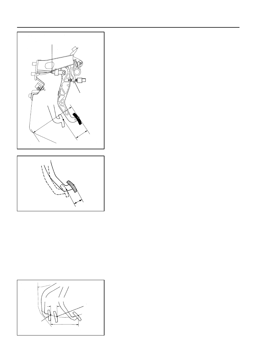
Push Rod Play and
Freeplay Adjust Point
Pedal
Height
Pedal Height
Adjust Point
Push Rod Play
CL03Z-01
CL0102
Pedal Freeplay
Z13785
25 mm (0.98 in.) or more
Full Pedal Stroke
Full Stroke
End Position
Release
Point
-
CLUTCH
CLUTCH PEDAL
CL-3
1544
Author:
Date:
1997 SUPRA (RM502U)
CLUTCH PEDAL
INSPECTION
1.
CHECK PEDAL HEIGHT
Pedal height from asphalt sheet:
146.2 - 156.2 mm (5.76 - 6.15 in.)
2.
IF NECESSARY, ADJUST PEDAL HEIGHT
Loosen the lock nut and clutch switch until the height is correct.
Tighten the lock nut.
HINT:
Before rotating the clutch switch for pedal height adjustment,
disconnect the clutch switch connector.
3.
CHECK PEDAL FREEPLAY AND PUSH ROD PLAY
Push in on the pedal until the beginning of clutch resistance is
felt.
Pedal freeplay: 5.0 - 15.0 mm (0.197 - 0.591 in.)
Gently push on the pedal until the resistance begins to increase
a little.
Push rod play at pedal top:
1.0 - 5.0 mm (0.039 - 0.197 in.)
4.
IF NECESSARY, ADJUST PEDAL FREEPLAY AND
PUSH ROD PLAY
(a)
Loosen the lock nut and turn the push rod until the free-
play and push rod play are correct.
(b)
Tighten the lock nut.
(c)
After adjusting the pedal freeplay, check the pedal height.
5.
INSPECT FULL PEDAL STROKE
Full pedal stroke: 132.0 - 138.0 mm (5.20 - 5.43 in.)
6.
INSPECT CLUTCH RELEASE POINT
(a)
Pull the parking brake lever and install wheel stopper.
(b)
Start the engine and idle the engine.
(c)
Without depressing the clutch pedal, slowly shift the shift
lever into the reverse position until the gears contact.
(d)
Gradually depress the clutch pedal and measure the
stroke distance from the point the gear noise stops (re-
lease point) up to the full stroke end position.
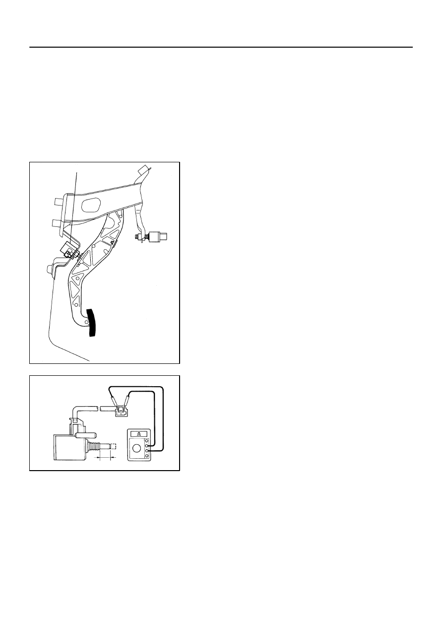
Q04185
Clutch Start Switch
Q00617
8
±
0.5 mm
(0.31
± 0.020 in.)
CL-4
-
CLUTCH
CLUTCH PEDAL
1545
Author:
Date:
1997 SUPRA (RM502U)
Standard distance: 25 mm (0.98 in.) or more
(From pedal stroke end position to release point)
If the distance is not as specified, do the following operation.
Inspect pedal height.
Inspect push rod play and pedal freeplay.
Bleed the clutch line.
Inspect the clutch cover and disc.
7.
CHECK CLUTCH START SYSTEM
(a)
Check that the engine does not start when the clutch ped-
al is released.
(b)
Check that the engine starts when the clutch pedal is fully
depressed.
If necessary, adjust or replace the clutch start switch.
8.
INSPECT CONTINUITY OF CLUTCH START SWITCH
(a)
Check that there is continuity between the terminals when
the switch is ON (pushed).
(b)
Check that there is no continuity between the terminals
when the switch is OFF (free).
If continuity is not as specified, replace the switch.
CL040-01
Z16903
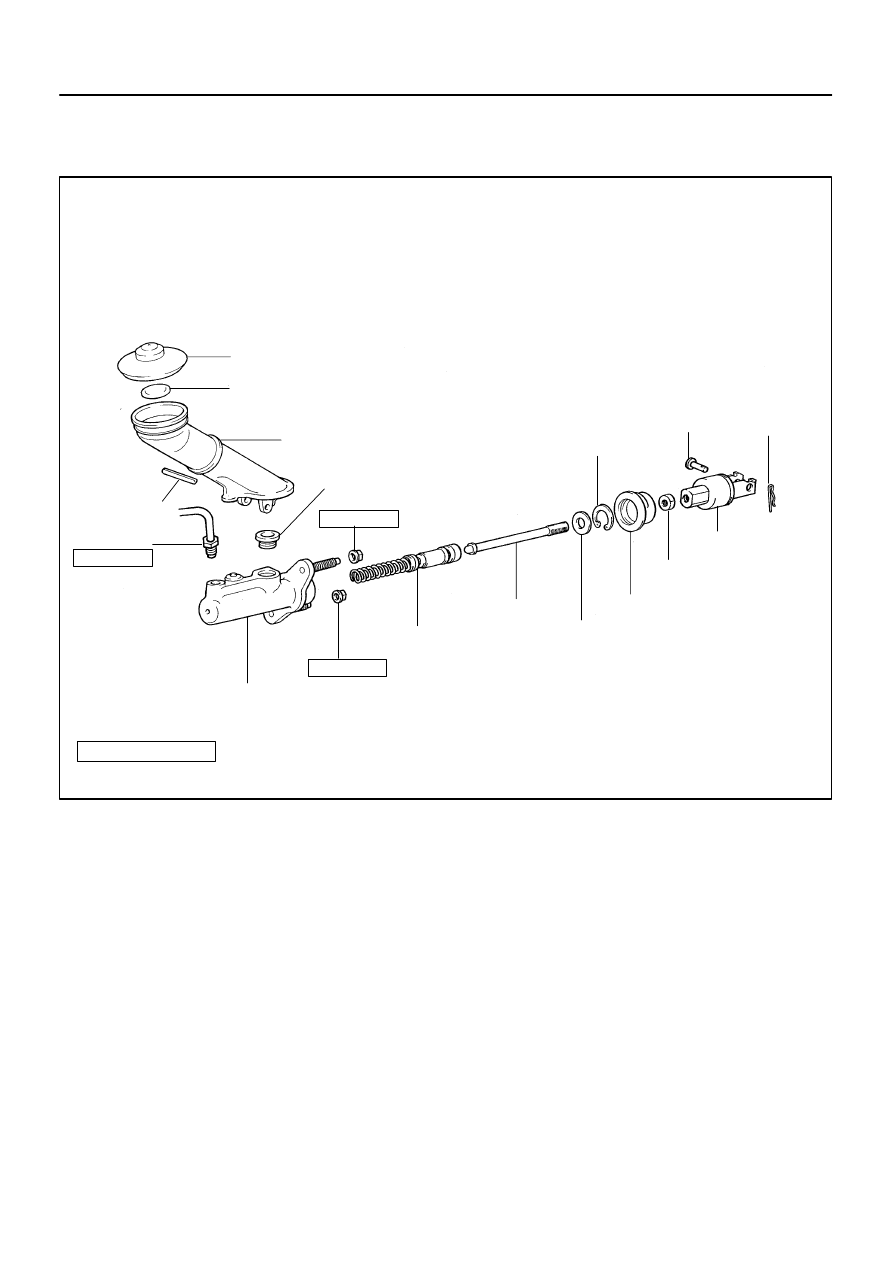
Filler Cap
Reservoir Tank
Slotted Spring
Pin
Clutch Line
Push Rod
Grommet
Float
Clip
Pin
Clevis
Boot
Washer
Snap Ring
Lock Nut
15 (155, 11)
12 (125, 9)
12 (125, 9)
N·m (kgf·cm, ft·lbf)
: Specified torque
Non-reusable part
Piston
Master Cylinder Body
-
CLUTCH
CLUTCH MASTER CYLINDER
CL-5
1546
Author:
Date:
1997 SUPRA (RM502U)
CLUTCH MASTER CYLINDER
COMPONENTS

CL041-01
Q04188
SST
CL-6
-
CLUTCH
CLUTCH MASTER CYLINDER
1547
Author:
Date:
1997 SUPRA (RM502U)
REMOVAL
1.
DRAIN OUT FLUID WITH SYRINGE
2.
DISCONNECT CLUTCH LINE UNION
Using SST, disconnect the union nut.
SST
09023-00100
Torque: 15 N·m (155 kgf·cm, 11 ft·lbf)
3.
REMOVE CLIP AND PIN
4.
REMOVE 2 MOUNTING NUTS AND PULL OUT MAS-
TER CYLINDER
Torque: 12 N·m (125 kgf·cm, 9 ft·lbf)
CL042-01
Q04189
Q04190
-
CLUTCH
CLUTCH MASTER CYLINDER
CL-7
1548
Author:
Date:
1997 SUPRA (RM502U)
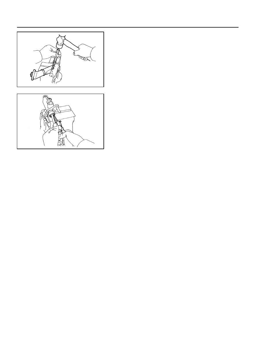
DISASSEMBLY
1.
REMOVE RESERVOIR TANK
(a)
Using a pin punch and hammer, drive out the slotted
spring pin.
(b)
Remove the reservoir tank and grommet.
2.
REMOVE PUSH ROD
(a)
Pull back the boot, and using snap ring pliers, remove the
snap ring.
(b)
Pull out the push rod.
3.
REMOVE PISTON
CL044-01
Z08053
Q04313
Protrusion
1.5 - 3.5 mm
(0.059 - 0.138 in.)
CL-8
-
CLUTCH
CLUTCH MASTER CYLINDER
1549
Author:
Date:
1997 SUPRA (RM502U)
REASSEMBLY
1.
COAT PARTS WITH LITHIUM SOAP BASE GLYCOL
GREASE, AS SHOWN
2.
INSERT PISTON INTO CYLINDER
3.
INSTALL PUSH ROD ASSEMBLY WITH NEW SNAP
RING
4.
INSTALL RESERVOIR TANK
(a)
Install the reservoir tank and a new grommet.
(b)
Using a pin punch and hammer, drive in the slotted spring
pin.
MT06M-02
-
MANUAL TRANSMISSION (V160)
TROUBLESHOOTING
MT-1
1569
Author:
Date:
1997 SUPRA (RM502U)
TROUBLESHOOTING
PROBLEM SYMPTOMS TABLE
Use the table below to help you find the cause of the problem. The numbers indicate the priority of the likely
cause of the problem. Check each part in order. If necessary, replace these parts.
Symptom
Suspect Area
See page
Noise
1. Flywheel damper
2. Oil (Level low)
3. Oil (Wrong)
4. Gear (Worn or damaged)
5. Bearing (Worn or damaged)
-
-
Oil leakage
1. Oil (Level too high)
2. Gasket (Damaged)
3. Oil seal (Worn or damaged)
4. O-Ring (Worn or damaged)
-
Hard to shift or will not shift
1. Synchronizer ring (Worn or damaged)
2. Shift key spring (Damaged)
-
-
Jumps out of gear
1. Locking ball spring (Damaged)
2. Shift fork (Worn)
3. Gear (Worn or damaged)
4. Bearing (Worn or damaged)
-
-
-
-
MT06N-01
D01920
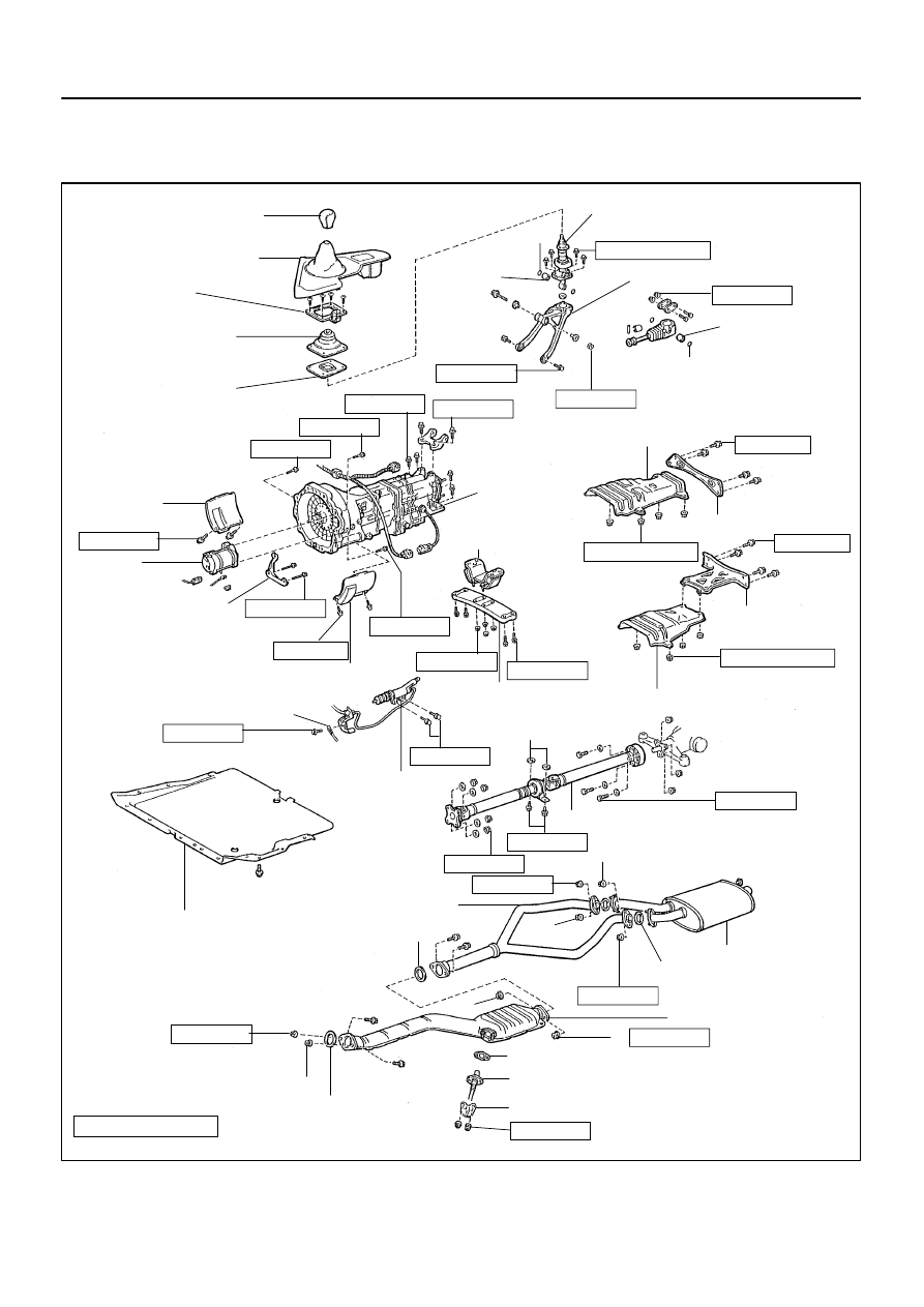
Shift Lever Knob
Upper Console Panel
Shift Lever Boot
Retainer
Shift Lever Retainer
Shift and Select Lever
Boot No.1
x5
Service Hole
Cover
Starter
Pipe Support Bracket
Service Hole Cover
Ground Cable
Engine Under Cover
Oxygen Sensor
Exhaust Front Pipe
Exhaust Tail Pipe
Exhaust Center Pipe
Propeller Shaft
Crossmember Brace
Heat Insulator
Engine Rear
Mounting
Adjusting Washer
Bushing
Transmission Shift Lever
Clutch Release Cylinder
N·m (kgf·cm, ft·lbf)
Shift and Select Lever
Boot No.2
Oxygen Sensor Cover
: Specified torque
Rear Engine Mounting
Member
Non-reusable part
Gasket
Gasket
Gasket
Gasket
19 (195, 14)
72 (730, 53)
12 (120, 9)
79 (805, 58)
49 (500, 36)
19 (195, 14)
56 (570, 41)
12 (120, 9)
37 (380, 27)
12 (120, 9)
25 (260, 19)
13 (135, 10)
39 (400, 29)
5.5 (55, 48 in.·lbf)
13 (130, 9)
13 (130, 9)
5.5 (55, 48 in.·lbf)
Heat Insulator
72 (730, 53)
39 (400, 29)
25 (250, 18)
19 (195, 14)
19 (195, 14)
7.8 (80, 69 in.·lbf)
Bushing
19 (195, 14)
Normal Roof:
Sport Roof:
58 (590, 43)
Transmission
Crossmember
Brace
20 (200, 14)
25 (250, 18)
58 (590, 43)
MT-2
-
MANUAL TRANSMISSION (V160)
MANUAL TRANSMISSION UNIT
1570
Author:
Date:
1997 SUPRA (RM502U)
MANUAL TRANSMISSION UNIT
COMPONENTS
MT06O-01
Q04417
Q06365
Q09475
Filler Plug
Drain Plug
Oil Level
0 - 5 mm
Q04419
R06858
-
MANUAL TRANSMISSION (V160)
MANUAL TRANSMISSION UNIT
MT-3
1571
Author:
Date:
1997 SUPRA (RM502U)
REMOVAL
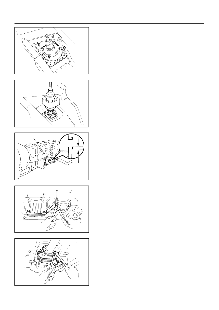
1.
REMOVE UPPER CONSOLE PANEL, SHIFT LEVER
BOOT RETAINER AND SHIFT AND SELECT LEVER
BOOTS NO.1 AND NO.2
(a)
Remove the shift lever knob.
(b)
Using a screwdriver, pry out the upper console panel.
(c)
Remove the 4 bolts and boot retainer.
(d)
Remove the shift and select lever boots No.1 and No.2.
2.
REMOVE 4 TRANSMISSION SHIFT LEVER SET
BOLTS
Torque: 7.8 N·m (80 kgf·cm, 69 in.·lbf)
3.
RAISE VEHICLE
NOTICE:
Make sure that the vehicle is securely supported.
4.
DRAIN TRANSMISSION OIL
Oil type: TOYOTA GEAR OIL V160 or ESSO ATF
DEXRON
®
D-21065
Capacity: 1.8 liters (1.9 US qts, 1.6 Imp. qts)
Torque: 39 N·m (400 kgf·cm, 29 ft·lbf)
5.
REMOVE ENGINE UNDER COVER
6.
REMOVE EXHAUST FRONT PIPE AND PIPE SUP-
PORT BRACKET
(a)
Remove the 2 nuts, cover, oxygen sensor and gasket.
Torque: 20 N·m (200 kgf·cm, 14 ft·lbf)
(b)
Remove the 2 bolts, nuts and gasket.
Torque: 58 N·m (590 kgf·cm, 43 ft·lbf)
(c)
Remove the 2 bolts and pipe support bracket from the
clutch housing.
Torque: 37 N·m (380 kgf·cm, 27 ft·lbf)
(d)
Remove the 2 bolts, nuts and gasket.
Torque: 58 N·m (590 kgf·cm, 43 ft·lbf)
(e)
Remove the exhaust front pipe.
Q04128
Q06366
Q04133
MT-4
-
MANUAL TRANSMISSION (V160)
MANUAL TRANSMISSION UNIT
1572
Author:
Date:
1997 SUPRA (RM502U)
7.
REMOVE EXHAUST CENTER PIPE
(a)
Remove the 4 nuts and 2 gaskets.
Torque: 19 N·m (195 kgf·cm, 14 ft·lbf)
(b)
Disconnect the exhaust center pipe from the 2 rings.
(c)
Remove the exhaust center pipe.
8.
REMOVE HEAT INSULATOR
Remove the 4 nuts and heat insulator.
Torque: 5.4 N·m (55 kgf·cm, 48 in.·lbf)
9.
REMOVE CROSSMEMBER BRACE
Remove the 4 bolts (Normal Roof) or 6 bolts (Sport Roof) and
crossmember brace.
Torque: 13 N·m (130 kgf·cm, 9 ft·lbf)
10.
REMOVE PROPELLER SHAFT
(See page
11.
REMOVE TRANSMISSION SHIFT LEVER
(a)
Remove the bolt and nut.
(b)
Remove the transmission shift lever, inside the vehicle.
Torque: 19 N·m (195 kgf·cm, 14 ft·lbf)
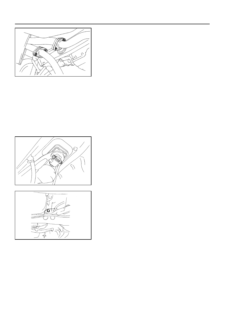
12.
REMOVE CLUTCH RELEASE CYLINDER AND
GROUND CABLE
(a)
Remove the bolt, clamp and ground cable.
Torque: 72 N·m (730 kgf·cm, 53 ft·lbf)
(b)
Remove the 2 bolts and clutch release cylinder.
Torque: 12 N·m (120 kgf·cm, 9 ft·lbf)
13.
DISCONNECT STARTER WIRE
(a)
Remove the nut and disconnect the starter wire.
(b)
Disconnect the starter wire connector.
14.
DISCONNECT VEHICLE SPEED SENSOR AND
BACK-UP LIGHT SWITCH CONNECTORS
Q04136
Matchmarks
Q04137
Q04138
Q04341
Q04141
A
B
A
-
MANUAL TRANSMISSION (V160)
MANUAL TRANSMISSION UNIT
MT-5
1573
Author:
Date:
1997 SUPRA (RM502U)
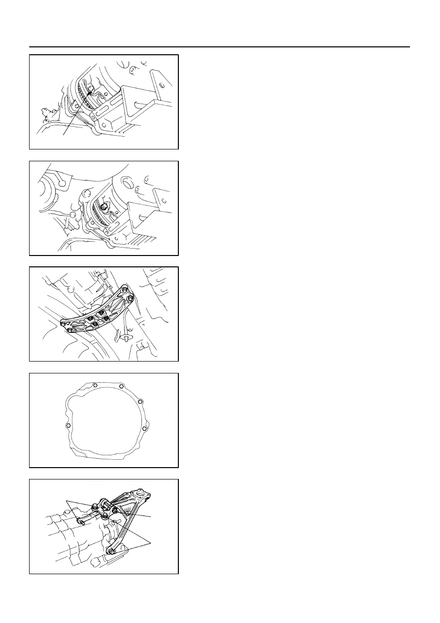
15.
REMOVE CLUTCH COVER SET BOLT
(a)
Remove the 2 bolts and service hole cover.
Torque: 12 N·m (120 kgf·cm, 9 ft·lbf)
(b)
Place matchmarks on the flywheel and clutch cover.
(c)
Remove the 6 bolts.
Torque: 19 N·m (195 kgf·cm, 14 ft·lbf)
16.
JACK UP TRANSMISSION SLIGHTLY
Using a transmission jack, support the transmission.
17.
REMOVE REAR ENGINE MOUNTING MEMBER
Remove the 4 nuts, bolts and rear engine mounting member.
Torque:
Nut: 13 N·m (135 kgf·cm, 10 ft·lbf)
Bolt: 25 N·m (260 kgf·cm, 19 ft·lbf)
18.
REMOVE STARTER
Lower the engine rear side and remove the 2 bolts and starter.
Torque: 39 N·m (400 kgf·cm, 29 ft·lbf)
19.
REMOVE TRANSMISSION
Remove the 5 transmission mounting bolts and transmission
from the engine.
Torque: 72 N·m (730 kgf·cm, 53 ft·lbf)
20.
REMOVE SHIFT LEVER RETAINER
Remove the 5 bolts, nut and shift lever retainer from the trans-
mission.
Torque:
Bolt A: 19 N·m (195 kgf·cm, 14 ft·lbf)
Nut B: 25 N·m (250 kgf·cm, 18 ft·lbf)
21.
REMOVE ENGINE REAR MOUNTING
Remove the 4 bolts and engine rear mounting from the trans-
mission.
Torque: 25 N·m (250 kgf·cm, 18 ft·lbf)
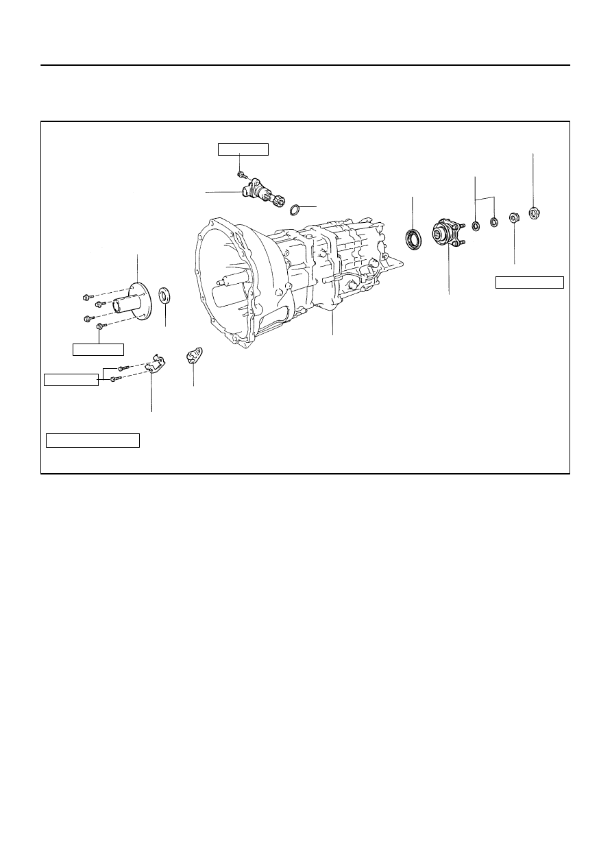
MT06Q-01
Q08612
Companion Flange
10 (100, 7)
Oil Seal
Vehicle Speed Sensor
Adjusting Washer
Transmission
Lock Plate
Lock Nut
11 (110, 8)
O-Ring
Release Fork Support
Release Fork Support Spring
Front Bearing Retainer
26 (260, 19)
Oil Seal
Non-reusable part
N·m (kgf·cm, ft·lbf)
Precoated part
: Specified torque
120 (1,220, 88)
-
MANUAL TRANSMISSION (V160)
OIL SEAL
MT-7
1575
Author:
Date:
1997 SUPRA (RM502U)
OIL SEAL
COMPONENTS
MT06R-02
Q04145
Q04146
SST
Q04147
SST
Q04148
SST
Q04149
SST
MT-8
-
MANUAL TRANSMISSION (V160)
OIL SEAL
1576
Author:
Date:
1997 SUPRA (RM502U)
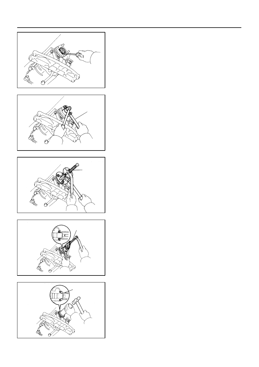
REPLACEMENT
1.
REPLACE TRANSMISSION REAR OIL SEAL
(a)
Remove the propeller shaft.
(See page
(b)
Using a screwdriver, remove the lock plate.
(c)
Using SST to hold the flange, remove the lock nut.
SST
09330-00021
(d)
Remove the 2 adjusting washers.
(e)
Using SST, remove the companion flange.
SST
09950- 30010 (09951- 03010, 09953- 03010,
09954-03010, 09955-03030, 09956-03030)
(f)
Using SST, remove the oil seal.
SST
09308-10010
(g)
Using SST and a hammer, install a new oil seal.
SST
09308-14010, 09309-14040
Q04147
SST
Q04150
SST
Q04151
”A”
”B”
Q04150
SST
-
MANUAL TRANSMISSION (V160)
OIL SEAL
MT-9
1577
Author:
Date:
1997 SUPRA (RM502U)
(h)
Heat the companion flange in an oven.
Companion flange temperature:
80 - 90
°
C (176 - 194
°
F)
(i)
Apply gear oil to the output shaft and install the compan-
ion flange.
(j)
Using SST, install the companion flange to the output
shaft.
SST
09950- 30010 (09951- 03010, 09953- 03010,
09954-03010, 09955-03030, 09956-03030)
(k)
Using SST to hold the flange, temporary install and torque
the lock nut.
SST
09330-00021
Torque: 190 N·m (1,940 kgf·cm, 140 ft·lbf)
(l)
Remove the lock nut.
(m)
Using a caliper gauge, measure dimension ”A” and di-
mension ”B”.
(n)
Calculate the required thickness of the adjusting shim.
Thickness:
(Dimension ”A” - Dimension ”B”) - (0.05
∼
0.14 mm,
0.0020
∼
0.0055 in.)
Adjusting shim thickness mm (in.)
Adjusting shim thickness mm (in.)
1.15 - 1.20 (0.0453 - 0.0472)
1.65 - 1.70 (0.0650 - 0.0669)
1.25 - 1.30 (0.0492 - 0.0512)
1.85 - 1.90 (0.0729 - 0.0748)
1.45 - 1.50 (0.0571 - 0.0591)
1.95 - 2.00 (0.0768 - 0.0787)
(o)
Install the selected shims to the output shaft.
(p)
Apply sealant to the nut threads.
Sealant:
Part No. 08833-00080, THREE BOND 1344, LOCTITE
242 or equivalent
(q)
Using SST to hold the flange, reinstall and torque the lock
nut.
SST
09330-00021
Torque: 120 N·m (1,220 kgf·cm, 88 ft·lbf)
Q04451
SST
Q04152
Q04153
Q04154
SST
Q03816
MT-10
-
MANUAL TRANSMISSION (V160)
OIL SEAL
1578
Author:
Date:
1997 SUPRA (RM502U)
(r)
Using SST and a hammer, install a new lock plate.
SST
09309-14010
HINT:
If necessary, using a pin punch and hammer, and tap the lock
plate.
(s)
Install the propeller shaft.
(See page
2.
REPLACE TRANSMISSION FRONT OIL SEAL
(a)
Remove the transmission.
(See page
)
(b)
Remove the 2 bolts and release fork support.
(c)
Remove the 4 bolts and front bearing retainer.
(d)
Using a hammer, tap in the screwdriver to the oil seal.
(e)
Pry out the oil seal.
(f)
Using SST and a hammer, install a new oil seal.
SST
09308-14010, 09309-14040
(g)
Install the transmission.
(See page
)
(h)
Install the front bearing retainer with the 4 bolts.
Torque: 10 N·m (100 kgf·cm, 7 ft·lbf)
(i)
Install the release fork support with the 2 bolts.
Torque: 26 N·m (260 kgf·cm, 19 ft·lbf)
3.
REPLACE VEHICLE SPEED SENSOR O-RING
(a)
Remove the transmission.
(See page
)
(b)
Remove the set bolt and driven gear.
(c)
Remove the O-ring from the driven gear.
(d)
Install a new O-ring to the driven gear.
(e)
Apply sealant to the bolt threads.
Sealant:
Part No. 08833-00080, THREE BOND 1344, LOCTITE
242 or equivalent

-
MANUAL TRANSMISSION (V160)
OIL SEAL
MT-1 1
1579
Author:
Date:
1997 SUPRA (RM502U)
(f)
Install the driven gear with the bolt.
Torque: 11 N·m (110 kgf·cm, 8 ft·lbf)
PR02H-01
-
PROPELLER SHAFT
TROUBLESHOOTING
PR-1
1674
Author:
Date:
1997 SUPRA (RM502U)
TROUBLESHOOTING
PROBLEM SYMPTOMS TABLE
Use the table below to help you find the cause of the problem. The numbers indicate the priority of the likely
cause of the problem. Check each part in order. If necessary, replace these parts.
Symptom
Suspect Area
See page
Noise
1. Center support bearing (Worn)
2. Sleeve yoke spline (Worn)
3. Spider bearing (Worn or stuck)
-
Vibration
1. Transmission extension housing rear bushing (Runout)
2. Sleeve yoke spline (Stuck)
3. Propeller shaft (Runout)
4. Propeller shaft (Imbalance)
-
-
-
PR06W-01
R06873
R06872
SST
R07096
120
°
Phasemarks
-
PROPELLER SHAFT
PROPELLER SHAFT ASSEMBLY
PR-1 1
1684
Author:
Date:
1997 SUPRA (RM502U)
INSTALLATION
1.
2JZ-GE:
INSTALL PROPELLER SHAFT
(a)
Apply grease to the flexible coupling centering bushings.
Grease:
Molybdenum disulfide lithium base, NLGI No.2.
(b)
Remove the SST.
(c)
Install the propeller shaft to the transmission.
(d)
Insert the propeller shaft from the vehicle’s rear and con-
nect the transmission and differential.
NOTICE:
Support the center support bearing by hand so that the
transmission and intermediate shaft, and propeller shaft
and differential, remain in a straight line.
(e)
Temporarily install the 2 center support bearing set bolts
with the adjusting washers.
HINT:
Use the adjusting washers which were removed.
(f)
Align the matchmarks and install the propeller shaft on
the differential with the 3 bolts, washers and nuts.
NOTICE:
Bolts should be inserted from the propeller shaft side.
Torque: 79 N·m (805 kgf·cm, 58 ft·lbf)
(g)
If using a new propeller shaft.
(1)
w/ Phasemarks:
Install the propeller shaft phasemarks and differen-
tial phasemarks so the their respective alignment
phasemarks match.
If the propeller shaft phasemarks and differential
phasemarks do not align, install the propeller shaft
and differential alignment phasemarks as close to-
gether as possible.
(2)
w/o Phasemarks:
Install the propeller shaft.
R07250
12.5
±
1 mm (0.492
±
0.04 in.)
R06873
Z10404
12.5
±
1 mm (0.492
±
0.04 in.)
PR-12
-
PROPELLER SHAFT
PROPELLER SHAFT ASSEMBLY
1685
Author:
Date:
1997 SUPRA (RM502U)
(h)
Torque the 2 center support bearing set bolts.
Torque: 49 N·m (500 kgf·cm, 36 ft·lbf)
HINT:
Adjust the center support bearing to keep the dimension, as
shown with the vehicle in the unladen condition.
Under the same condition, check if the center line of the center
support bearing is at right angles to the shaft axial direction.
2.
2JZ-GTE:
INSTALL PROPELLER SHAFT
(a)
Apply grease to the flexible coupling centering bushings.
Grease:
Molybdenum disulfide lithium base, NLGI No.1 or
No.2.
(b)
Align the matchmarks on the flanges and connect the
flanges with the 4 nuts and washers.
(c)
Torque the 4 nuts.
Torque: 56 N·m (570 kgf·cm, 41 ft·lbf)
(d)
Insert the propeller shaft from the vehicle’s rear and con-
nect the transmission and differential.
NOTICE:
Support the center support bearing by hand so that the
transmission and intermediate shaft, and propeller shaft
and differential, remain in a straight line.
(e)
Temporarily install the 2 center support bearing set bolts
with the adjusting washers.
HINT:
Use the adjusting washers which were removed.
(f)
Align the matchmarks and install the propeller shaft on
the differential with the 3 bolts, washers and nuts.
NOTICE:
Bolts should be inserted from the propeller shaft side.
Torque: 79 N·m (805 kgf·cm, 58 ft·lbf)
(g)
Torque the 2 center support bearing set bolts.
Torque: 49 N·m (500 kgf·cm, 36 ft·lbf)
HINT:
Adjust the center support bearing to keep the dimension, as
shown with the vehicle in the unladen condition.
Under the same condition, check if the center line of the center
support bearing is at right angles to the shaft axial direction.
R06864
SST
-
PROPELLER SHAFT
PROPELLER SHAFT ASSEMBLY
PR-13
1686
Author:
Date:
1997 SUPRA (RM502U)
(h)
Using SST, torque the adjust nut.
SST
09922-10010
Torque: 50 N·m (515 kgf·cm, 37 ft·lbf)
HINT:
Use torque wrench with a fulcrum length of 34.5 cm (13.6 in.).
3.
ADJUST PROPELLER SHAFT JOINT ANGEL (See
page
)
NOTICE:
The joint angle should be checked when the propeller shaft
is removed and installed.
4.
NORMAL ROOF:
INSTALL CENTER FLOOR CROSSMEMBER BRACE
Install the center floor crossmember brace and 4 bolts.
Torque: 13 N·m (130 kgf·cm, 9 ft·lbf)
5.
SPORT ROOF:
INSTALL CENTER FLOOR CROSSMEMBER BRACE
Install the center floor crossmember brace and 6 bolts.
Torque: 13 N·m (130 kgf·cm, 9 ft·lbf)
6.
INSTALL HEAT INSULATOR
Install the heat insulator and torque the 4 nuts.
Torque: 5.4 N·m (55 kgf·cm, 48 in.·lbf)
7.
INSTALL EXHAUST PIPE (See page EM-94)
8.
INSTALL OXYGEN SENSOR
Install the oxygen sensor with heat insulator and torque the 2
nuts.
Torque: 44 N·m (450 kgf·cm, 34 in.·lbf)
PR02N-02
R06878
R06879
R06880
SST
R01139
SST
PR-14
-
PROPELLER SHAFT
JOINT ANGLE
1687
Author:
Date:
1997 SUPRA (RM502U)
JOINT ANGLE
ADJUSTMENT
NOTICE:
When doing operations which involve the removal and
installation of the propeller shaft, always check the joint.
Make adjustments if necessary.
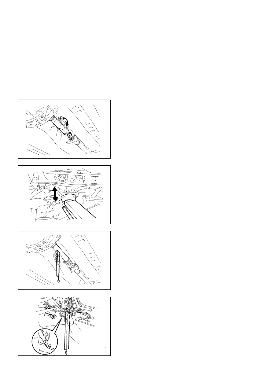
1.
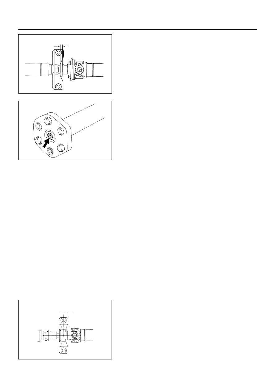
STABILIZE PROPELLER SHAFT AND DIFFERENTIAL
(a)
Turn the propeller shaft several times by hand to stabilize
the center support bearing and flexible couplings.
(b)
Using a jack, raise and lower the differential to stabilize
the differential mounting cushion.
2.
CHECK JOINT ANGLE OF NO.2 JOINT AND NO.3
JOINT
(a)
Using SST, measure the installation angle of the inter-
mediate shaft and propeller shaft.
SST
09370-50010
HINT:
The SST should be directly underneath the tube.
(b)
Using the SST, measure the installation angle of the dif-
ferential.
HINT:
Measure the installation angle by placing the SST in the posi-
tion, as shown in the illustration.
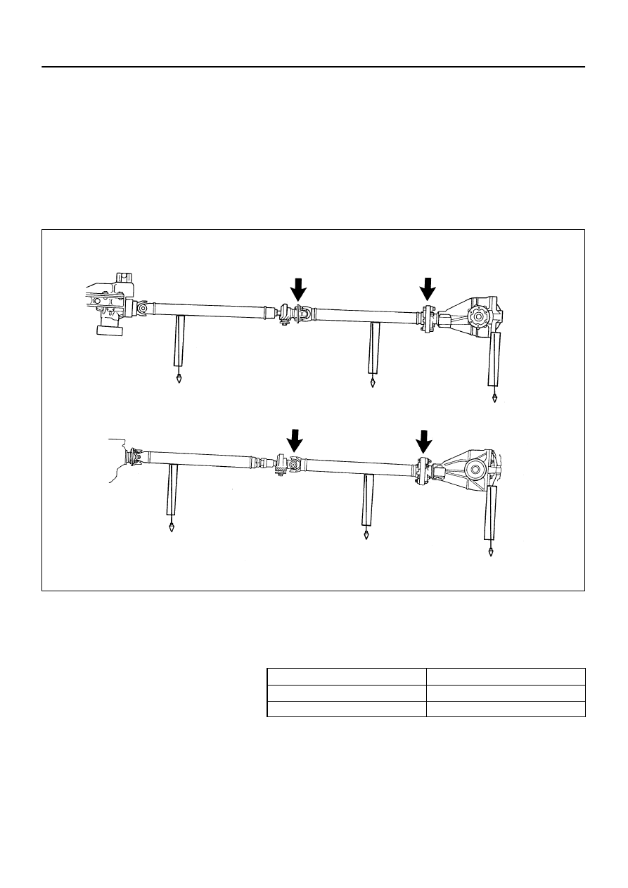
F01960
2JZ-GE
2JZ-GTE
No.2 Joint
No.3 Joint
A - B = -1
°
09’
±
36’
No.2 Joint
A - B = -1
°
09’
±
36’
B - C = 44’
±
36’
No.3 Joint
B - C = 44’
±
36’
Joint Angle - :
+ :
A
B
C
A
B
C
>
>
-
PROPELLER SHAFT
JOINT ANGLE
PR-15
1688
Author:
Date:
1997 SUPRA (RM502U)
(c)
Calculate the No.2 joint angle.
No.2 joint angle:
A - B = -1
°
09’
±
36’
A: Intermediate shaft installation angle
B: Propeller shaft installation angle
(d)
Calculate the No.3 joint angle.
No.3 joint angle:
B - C = 44’
±
36’
B: Propeller shaft installation angle
C: Differential installation angle
If the measured angle is not within the specification, adjust it
with the center support bearing adjusting washer and differen-
tial adjusting shim.
Center support bearing adjusting washer thickness
Thickness mm (in.)
Thickness mm (in.)
2.0 (0.079)
6.0 (0.236)
4.0 (0.157)
8.5 (0.335)
NOTICE:
Left and right washers should be the same thickness.
2 washers should not be assembled together.
Some vehicles are not assembled with washers.
R07370
-16’ -1’
R07371
PR-16
-
PROPELLER SHAFT
JOINT ANGLE
1689
Author:
Date:
1997 SUPRA (RM502U)
Differential adjusting shim thickness
Thickness mm (in.)
Thickness mm (in.)
1.0 (0.039)
2.0 (0.079)
1.6 (0.063)
-
NOTICE:
Left and right washers should be the same thickness.
This shim is installed on top of the upper mount stop-
per and it used for adjustment.
3.
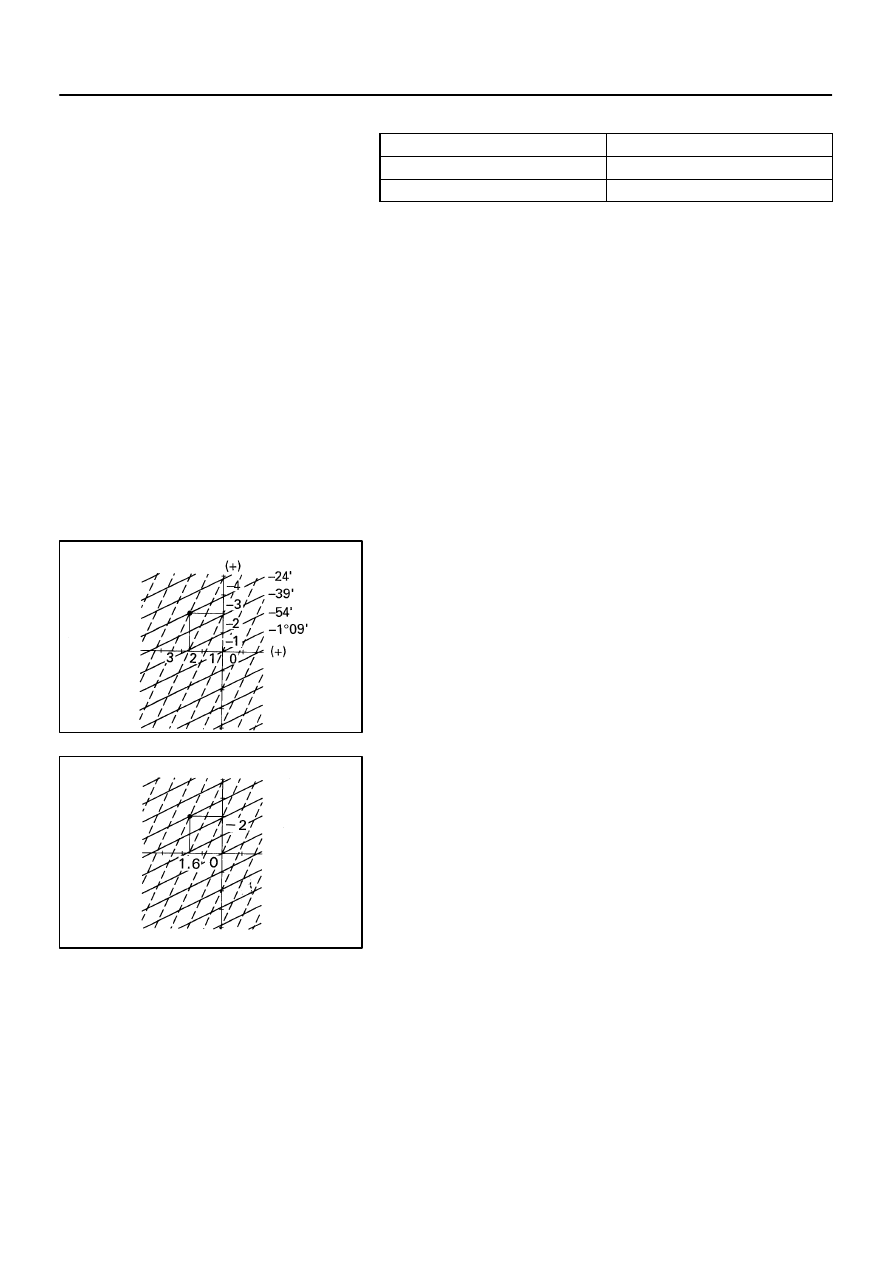
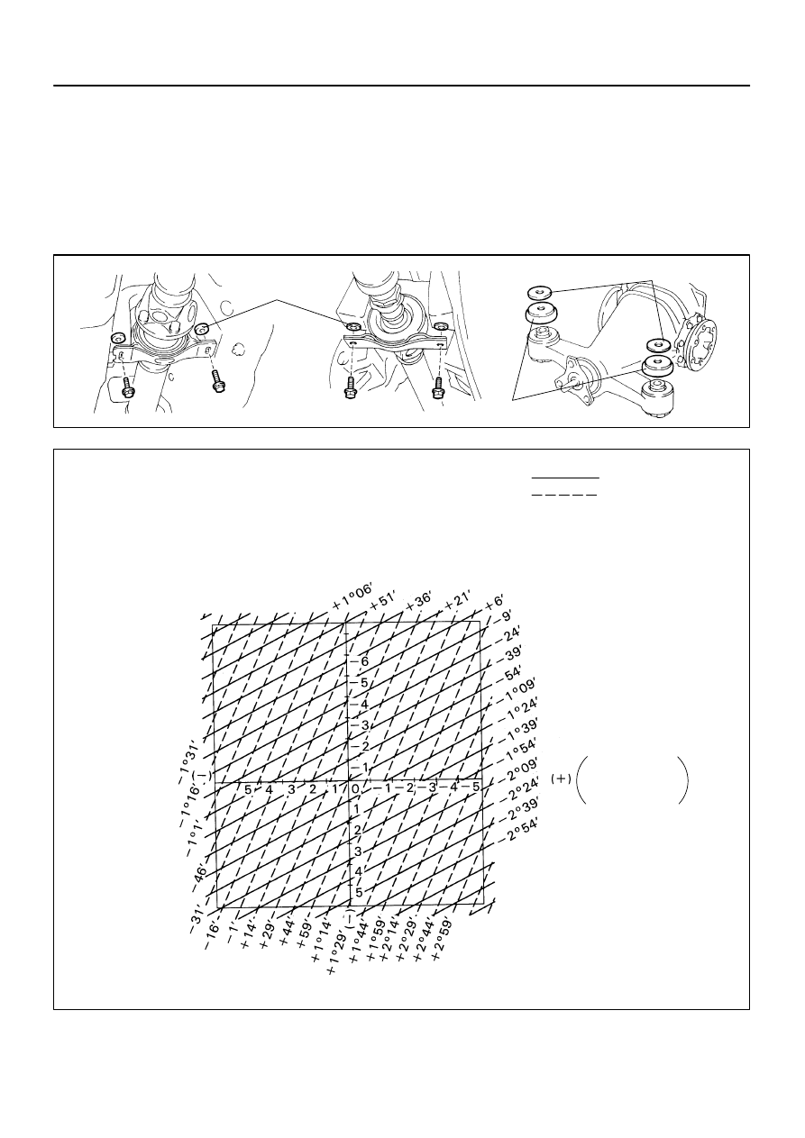
HOW TO READ THIS CHART
Take measurements, then calculate the No.2 and No.3 joint
angle.
Make the calculated values on the chart and read the coordi-
nates.
Replace the adjusting washer and shim in accordance with the
coordinates read and adjust the joint angles.
Example
Measurements (Installation angle):
Intermediate shaft: 1
°
50’
Propeller shaft: 2
°
14’
Differential: 2
°
15’
Joint angle:
No.2: 1
°
50’ - 2
°
14’ = -24’
No.3: 2
°
14’ - 2
°
15’ = -1
’
Adjustment:
Center support bearing
Standard parts: 4 mm - 2 mm = 2 mm
Use adjusting washers which are 2 mm (0.079 in.)
thicker.
Differential
Use adjusting shims which are 1.6 mm (0.063 in.)
thicker.
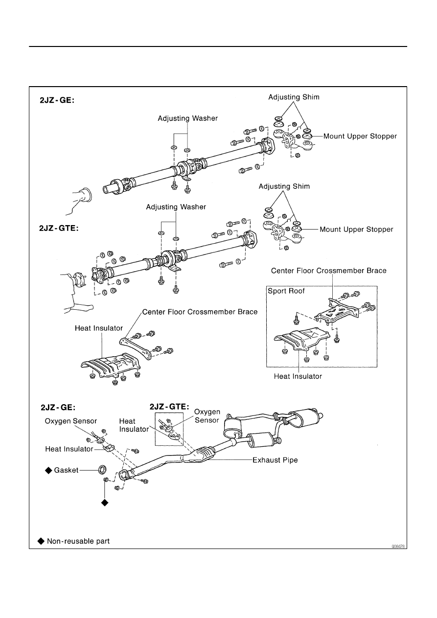
F03463
2JZ-GE
2JZ-GTE
Differential
Adjusting Washer
Adjusting Shim
Upper Mount Shim
R07372
ADJUSTMENT CHART
Center Support Bearing
(Adjusting Washer)
No.2 Joint Angle
Differential
Mount Upper
Stopper or
Adjusting Shim
(+)
No.3 Joint Angle
-
PROPELLER SHAFT
JOINT ANGLE
PR-17
1690
Author:
Date:
1997 SUPRA (RM502U)
HINT:
Maintain the same thickness for the adjusting washers
and adjusting shims on both the left and right sides.
If a washer and shim of the exact thickness are not avail-
able, use the parts which are the nearest in thickness.
NOTICE:
Check the joint angle once again after making the adjust-
ment.
PR06U-01
PR-2
-
PROPELLER SHAFT
PROPELLER SHAFT ASSEMBLY
1675
Author:
Date:
1997 SUPRA (RM502U)
PROPELLER SHAFT ASSEMBLY
COMPONENTS
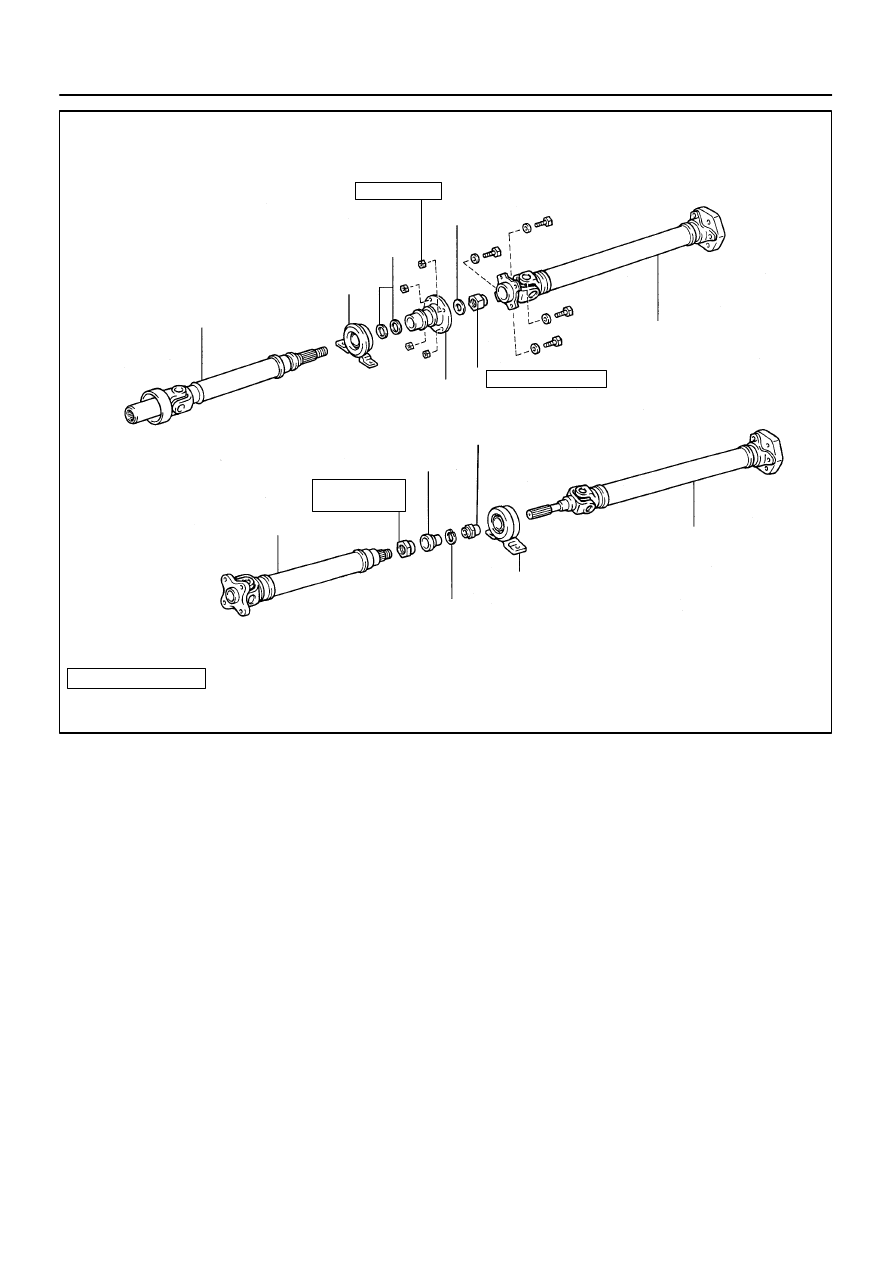
Q09642
2JZ-GE
2JZ-GTE
Intermediate Shaft Sub-assembly
Center Support Bearing
Washer
Washer Plate
Universal Joint Flange
Propeller Shaft
Intermediate Shaft Sub-assembly
Propeller Shaft
Center Support Bearing
Adjusting Nut Dust Boot
Dust Deflector
Snap Ring
Non-reusable part
: Specified torque
N·m (kgf·cm, ft·lbf)
See page
* For use with SST
69 (700, 51)
* 50 (515, 37)
74 (750, 54)
-
PROPELLER SHAFT
PROPELLER SHAFT ASSEMBLY
PR-3
1676
Author:
Date:
1997 SUPRA (RM502U)
PR06V-01
R06868
R07621
Matchmarks
PR-4
-
PROPELLER SHAFT
PROPELLER SHAFT ASSEMBLY
1677
Author:
Date:
1997 SUPRA (RM502U)
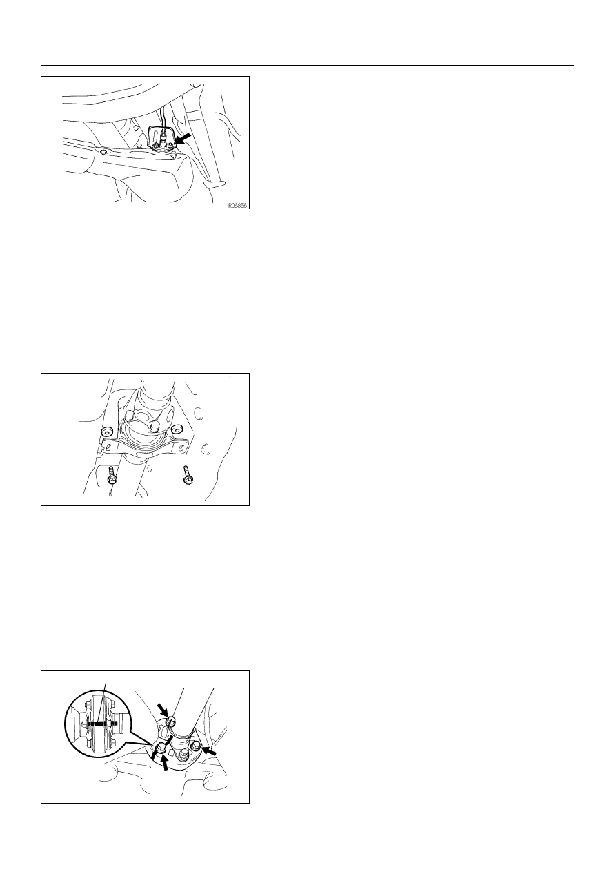
REMOVAL
1.
REMOVE OXYGEN SENSOR
(a)
Remove the 2 bolts.
(b)
Remove the oxygen sensor and heat insulator.
2.
REMOVE EXHAUST PIPE (See page EM-94)
3.
REMOVE HEAT INSULATOR
Remove the 4 nuts and heat insulator.
4.
NORMAL ROOF:
REMOVE CENTER FLOOR CROSSMEMBER BRACE
Remove the 4 bolts and crossmember brace.
5.
SPORT ROOF:
REMOVE CENTER FLOOR CROSSMEMBER BRACE
Remove the 6 bolts and crossmember brace.
6.
2JZ-GE:
REMOVE PROPELLER SHAFT
(a)
Remove the 2 center support bearing set bolts and ad-
justing washers.
HINT:
Production vehicles are not equipped with adjusting washers.
NOTICE:
When removing the set bolts, support the center support
bearing by hand so that the transmission and intermediate
shaft, and propeller shaft and differential, remain in a
straight line.
(b)
Place matchmarks on the differential companion flange
and flexible coupling.
(c)
Remove the 3 bolts inserted in the differential companion
flange.
NOTICE:
The bolts inserted in the propeller shaft companion flange
should not be removed.
R08621
R06872
SST
R06864
SST
R06865
Matchmarks
R08620
-
PROPELLER SHAFT
PROPELLER SHAFT ASSEMBLY
PR-5
1678
Author:
Date:
1997 SUPRA (RM502U)
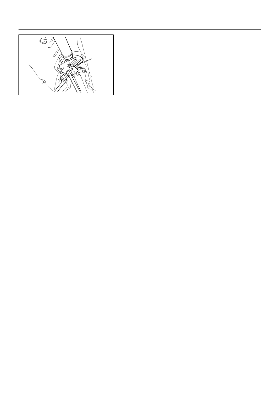
(d)
Separate the flexible coupling from the differential side.
HINT:
If the flexible coupling cannot be easily separated by hand, in-
sert a screwdriver into the bolt hole of the flexible coupling, as
shown in the illustration, then pry the coupling out.
NOTICE:
Do not bring the screwdriver blade in direct contact with
the flexible coupling’s rubber portion.
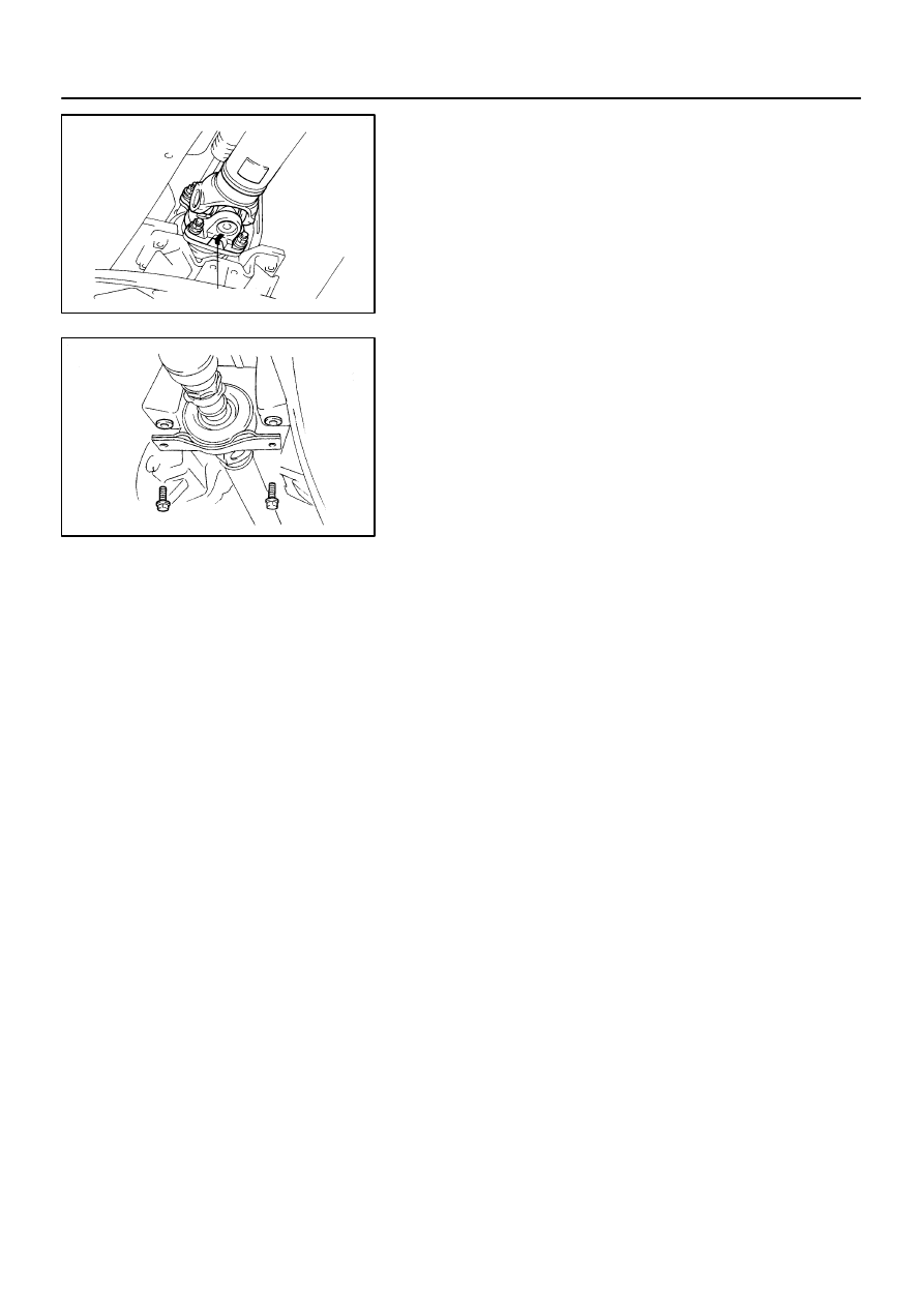
(e)
Pull the yoke from the transmission.
(f)
M/T:
Install SST in the transmission to prevent oil leakage.
SST
09325-20010
(g)
A/T:
Install SST in the transmission to prevent oil leakage.
SST
09325-40010
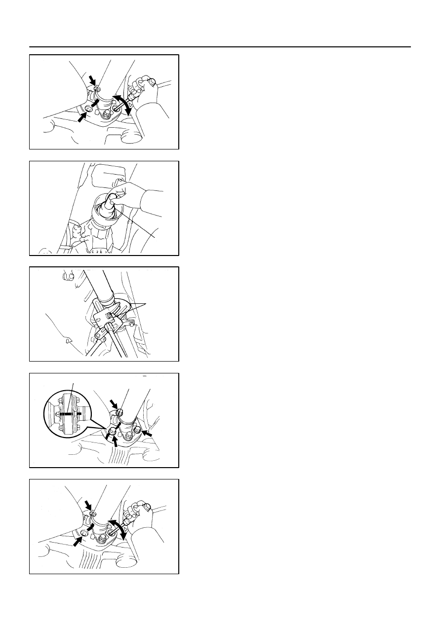
7.
2JZ-GTE:
REMOVE PROPELLER SHAFT
(a)
Using SST, loosen the adjusting nut until it can be turned
by hand.
SST
09922-10010
HINT:
Use 2 of the same type SST.
(b)
Place matchmarks on the differential companion flange
and flexible coupling.
(c)
Remove the 3 bolts inserted in the differential companion
flange.
NOTICE:
The bolts inserted in the propeller shaft companion flange
should not be removed.
(d)
Separate the flexible coupling from the differential side.
HINT:
If the flexible coupling cannot be easily separated by hand, in-
sert a screwdriver into the bolt hole of the flexible coupling, as
shown in the illustration, then pry the coupling out.
NOTICE:
Do not bring the screwdriver blade in direct contact with
the flexible coupling’s rubber portion.
R06869
Matchmarks
R06867
PR-6
-
PROPELLER SHAFT
PROPELLER SHAFT ASSEMBLY
1679
Author:
Date:
1997 SUPRA (RM502U)
(e)
Place matchmarks on the transmission companion
flange and propeller shaft flange.
(f)
Remove the 4 washers and nuts.
(g)
Remove the 2 center support bearing set bolts and ad-
justing washers.
HINT:
Some vehicles are not equipped with and adjusting washer.
NOTICE:
When removing the set bolts, support the center support
bearing by hand so that the transmission and intermediate
shaft, and propeller shaft and differential, remain in a
straight line.
(h)
Remove the propeller shaft from the transmission.
(i)
Push the rear propeller shaft straight forward to compress
the propeller shaft and pull out the propeller shaft from the
centering pin of the differential.
NOTICE:
Press the propeller shaft straight ahead to keep the trans-
mission and intermediate shaft aligned straight.
(j)
Pull the propeller shaft out toward the vehicle’s rear.
NOTICE:
The intermediate shaft and propeller shaft should not be
separated.
PR02K-01
PR0260
R07008
R06873
R01130
R01131
-
PROPELLER SHAFT
PROPELLER SHAFT ASSEMBLY
PR-7
1680
Author:
Date:
1997 SUPRA (RM502U)
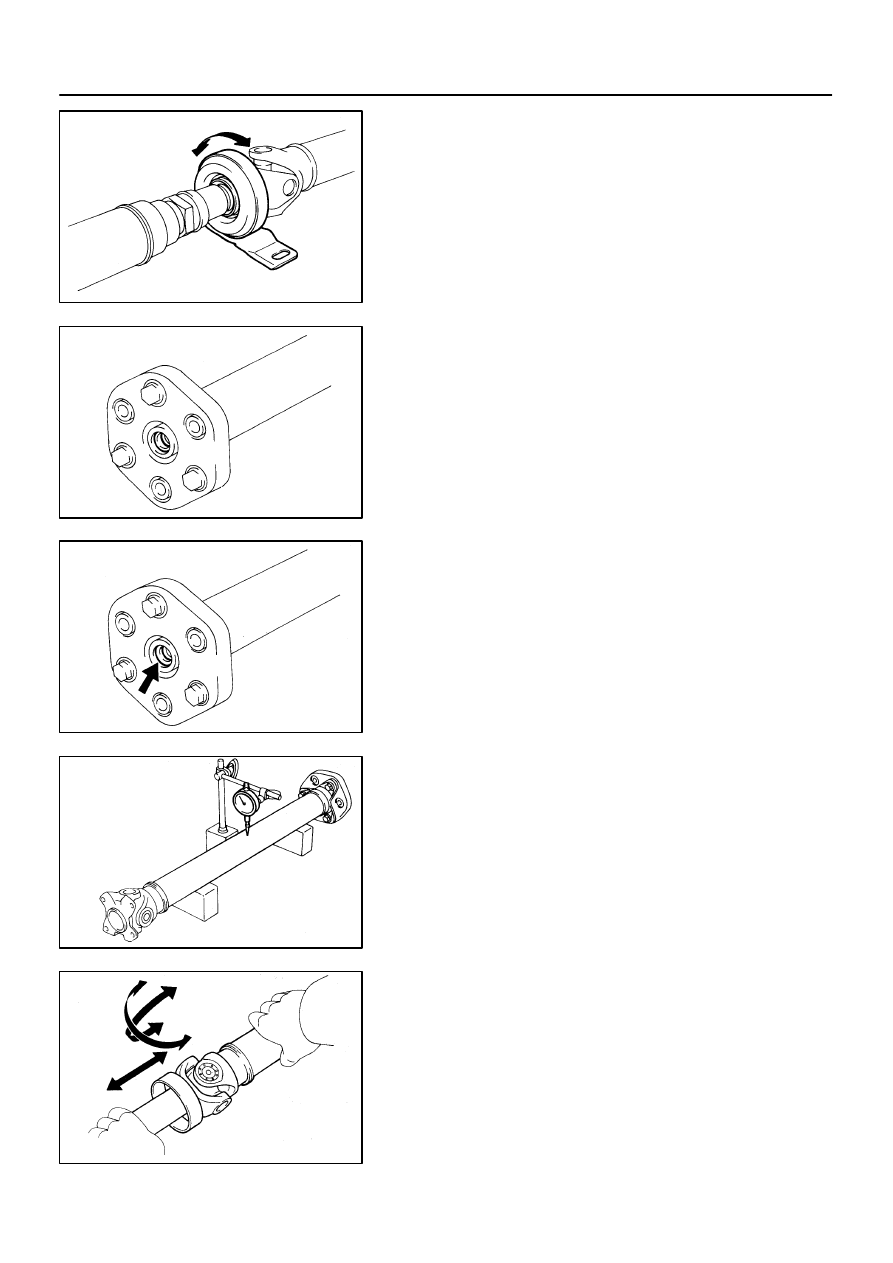
INSPECTION
1.
INSPECT CENTER SUPPORT BEARING
(a)
Check if the bearing turns smoothly.
(b)
Check for crack in or damage to the cushion.
If the center support bearing is damaged, worn or does not turn
smoothly, replace it.
2.
INSPECT FLEXIBLE COUPLINGS
Check for cracks in or damage to rear flexible couplings.
If the flexible coupling is damaged, replace the propeller shaft
assembly.
3.
INSPECT FLEXIBLE COUPLING CENTERING BEAR-
ING
Check for damage to the bushing.
If the bushing is damaged, replace the propeller shaft assem-
bly.
4.
INSPECT RUNOUT OF INTERMEDIATE SHAFT AND
PROPELLER SHAFT
Maximum runout: 0.8 mm (0.031 in.)
If the runout is greater than the maximum, replace the propeller
shaft assembly.
5.
INSPECT SPIDER BEARING
(a)
Check if the spider bearing rotates smoothly.
(b)
Check if there any play in the spider bearing.
If necessary, replace the propeller shaft assembly.
PR02L-01
R06958
Matchmarks
R01128
SST
R01129
Matchmarks
R06959
Front
PR-8
-
PROPELLER SHAFT
PROPELLER SHAFT ASSEMBLY
1681
Author:
Date:
1997 SUPRA (RM502U)
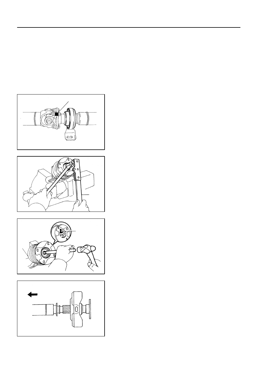
REPLACEMENT
NOTICE:
Be careful not to grip the propeller shaft tube too tightly in
the vise as this will cause deformation.
1.
2JZ-GE:
REPLACE CENTER SUPPORT BEARING
(a)
Separate the propeller shaft and intermediate shaft.
(1)
Place matchmarks on the flanges.
(2)
Remove the 4 bolts, washers and nuts.
(b)
Remove the center support bearing from intermediate
shaft.
(1)
Using a chisel and hammer, loosen the staked part
of the nut.
(2)
Using SST to hold the flange, remove the nut.
SST
09930-00021
(3)
Remove the washer.
(4)
Place matchmarks on the flange and intermediate
shaft.
(5)
Using a brass and hammer, remove the flange, 2
washers and center support bearing from the inter-
mediate shaft.
(c)
Install a new center support bearing on intermediate
shaft.
HINT:
Install the center support bearing in the direction, as shown and
install the 2 washers.
(d)
Install the flange on intermediate shaft.
(1)
Coat the spline of the intermediate shaft with MP
grease.
R01132
Matchmarks
R01133
SST
R06958
Matchmarks
PR0239
Matchmarks
Q06357
SST
-
PROPELLER SHAFT
PROPELLER SHAFT ASSEMBLY
PR-9
1682
Author:
Date:
1997 SUPRA (RM502U)
(2)
Place the flange on the shaft and align the match-
marks.
HINT:
If replacing either the center flange or intermediate shaft, reas-
semble them so that the front yoke of the intermediate shaft and
the rear yoke of the propeller shaft are facing in the same direc-
tion.
(3)
Install the washer.
(4)
Using SST to hold the flange, press the bearing into
position by tightening down a new nut.
SST
09330-00021
Torque: 181 N·m (1,850 kgf·cm, 134 ft·lbf)
(5)
Loosen the nut.
(6)
Torque the nut again.
Torque: 69 N·m (700 kgf·cm, 51 ft·lbf)
(7)
Using a punch and hammer, stake the shaft.
(e)
Install the propeller shaft.
(1)
Align the matchmarks on the flanges and connect
the flanges with 4 bolts, washers and nuts.
HINT:
If replacing either the center flange or intermediate shaft, reas-
semble them so that the front yoke of the intermediate shaft and
the rear yoke of the propeller shaft are facing in the same direc-
tion.
(2)
Torque the 4 bolts and nuts.
Torque: 74 N·m (750 kgf·cm, 54 ft·lbf)
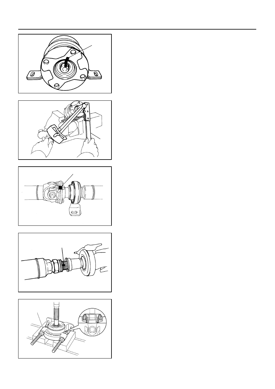
2.
2JZ-GTE:
REPLACE CENTER SUPPORT BEARING
(a)
Separate the intermediate shaft and propeller shaft.
(1)
Place matchmarks on the intermediate shaft and
propeller shaft.
(2)
Separate the intermediate shaft and propeller shaft.
(3)
Remove the dust boot from the propeller shaft.
HINT:
If the dust boot is reused, remove it after wrapping vinyl tape
around the spline, so it will not be damage.
(b)
Remove the center support bearing.
(1)
Using a snap ring expander, remove the snap ring.
(2)
Using SST, remove the center support bearing with
dust deflector.
SST
09950-00020
PR0228
SST
R07314
SST
PR0229
SST
PR0238
Vinyl Tape
PR-10
-
PROPELLER SHAFT
PROPELLER SHAFT ASSEMBLY
1683
Author:
Date:
1997 SUPRA (RM502U)
(c)
Install a new center support bearing.
(1)
Using SST and a press, install the center support
bearing.
SST
09330-50010
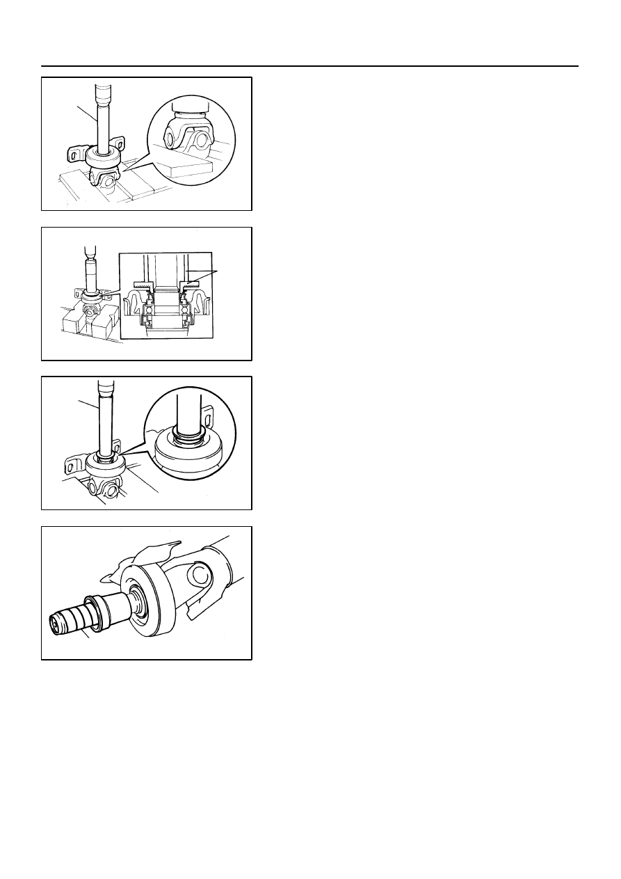
(2)
Using SST and a press, insert a new dust deflector
until it almost touches the rubber of the center sup-
port bearing.
SST
09608-00071, 09608-06041
(3)
Using SST and a press, install the dust deflector to
the end.
SST
09330-50010
(4)
Using a snap ring expander, install a new snap ring.
(d)
Assemble the intermediate shaft and propeller shaft.
(1)
Install the dust boot.
NOTICE:
Assemble after wrapping vinyl tape around the spline so it
will not damage the boot.
(2)
Apply grease to the spline.
Grease:
Molybdenum disulfide lithium base, NLGI No.2.
(3)
Align the matchmarks and assemble the intermedi-
ate shaft and propeller shaft.
(4)
Cover the adjusting nut with the dust boot.
(5)
Tighten the adjusting nut fully by hand.
Document Outline
- CL-1.pdf
- CL-10.pdf
- CL-11.pdf
- CL-12.pdf
- CL-13.pdf
- CL-20.pdf
- CL-21.pdf
- CL-22.pdf
- CL-25.pdf
- CL-3.pdf
- CL-5.pdf
- CL-6.pdf
- CL-7.pdf
- CL-8.pdf
- MT-1.pdf
- MT-2.pdf
- MT-3.pdf
- MT-7.pdf
- MT-8.pdf
- PR-1.pdf
- PR-11.pdf
- PR-14.pdf
- PR-2.pdf
- PR-4.pdf
- PR-7.pdf
- PR-8.pdf
Wyszukiwarka
Podobne podstrony:
1997 Clutch & V160
obiektywne metody oceny postawy ciała (win 1997 2003)
Konstytucja 2 kwietnia 1997
1997 (104)
Dz U 1997 109 704 R S u ba bezpiecze stwa i higi 3
1997 1 (10)
1997 Accent, 17521
KONSTYTUCJA RP z 02 kwietnia 1997
Golf4,5d, 1997 2003
1997 Accent, 17552
1997 Accent, 17543
Rozporządzenie Rady Ministrów z dnia 2 września 1997 r, rola służy BHP
1997 biofeedback relax training and cogn behav modif as treatment QJM
Kodeks karny RP 1997 id 238280 Nieznany
1997 Accent, 17549
1997 0704
1997 01 Pierwsze kroki w cyfrówce
PN B 02865 1997 Ochrona przeciwpożarowa budynków Przeciwpożarowe zaopatrzenie wodne Instalacja wodo
więcej podobnych podstron