Monster
T
TRA
VEL 175
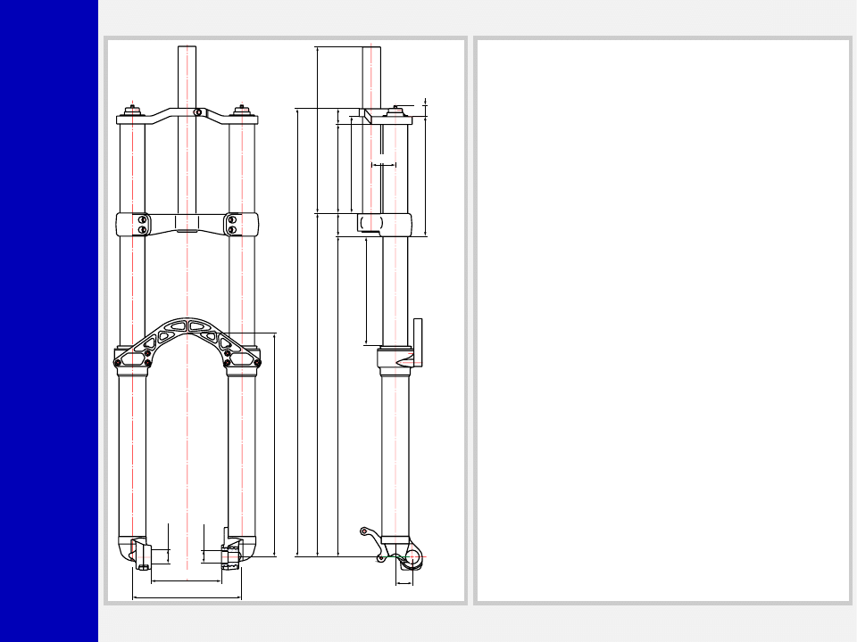
Travel 175
358
L.MAX=728
L.L.=718 L.MIN=543
550.5
513.5
192.5
155.5
267
142.5
25
17.4
38
37
±2
±2
175
Ø22
112.5
Ø20
+0.5
0
27
GENERAL
• The double plate fork is specifically designed for Downhill use.
Damped by hydraulic cartridges and sprung by a mechanical
coil spring system.
• Rebound damping cartridge inside each fork leg.
• Spring pre-load and rebound damping adjustment controlled via
external top mount adjusters.
• Stanchion tube secured to the crown and upper crown. The
system gives the fork unmatched structural strength.
• Parts subjected to friction are cooled and lubricated by specially
formulated oil.
• Left slider comes with brake caliper adapter.
• Axle support is the same drop-out design as in motorbikes, with
shaft threaded.
• Wheel shaft (20 mm diam.) available on request.
• Adapter kit for 3" wheel installation available on request.
Steer tube: EASTON aluminum steer tubes available for 1 1/8”
x267 mm, threadless.
Crown: Forged and CNC-machined “BAM” aluminum alloy.
Upper crown: CNC-machined aluminum alloy. Two versions
available for different frame sizes.
Arch: CNC-machined aluminum.
Stanchions: Anodized EASTON aluminum with variable butting,
diam. 40 mm.
Springs: with constant pitch.
Sliders: Forged and CNC-machined aluminum alloy
Slider bushing: 2 in each fork leg, composed of a copper base
and impregnated with an anti-friction coating.
Seals: Computer designed oil seals guarantee the highest quality
seals available.
Oil: Specially formulated oil which eliminates foaming and viscosity
breakdown while providing complete stiction-free performance.
Fork leg oil: 380 cc, type EBH 16- SAE 7.5.

Monster
T
GENERAL RULES
1. Where specified, assemble and disas-
semble the shock absorption system
using M
ARZOCCHI
special tools only.
2. On reassembling the suspension sys-
tem, always use new seals.
3. If two screws are close one to the other,
always tighten using a 1-2-1 sequence.
In short, screw the first screw just up to
the point it is well tightened, then tighten
the second screw and then go back to
the first one and screw it tighter.
4. Clean all metal parts with a special,
preferably biodegradable solvent, such
as trichloroethane or trichloroethylene.
5. Before reassembling, lubricate all parts
in contact with each other using sili-
cone fat spray or a specific oil for oil
seals.
6. Always grease the conic seal rings
before reassembling.
7. Use wrenches with metric size only.
Wrenches with inch size might dam-
age the fastening devices even when
their size is similar to that of the wrenches
in metric size.
INSTRUCTIONS

Monster
T
FAILURES, CAUSES AND REMEDIES
This paragraph reports some troubles that may occur when using the fork. It also indicates possible causes and suggests a remedy.
Always refer to this table before doing any repair work.
Oil leaking through the bottom of slider
O-ring seal on the cartridge nut is damaged
Replace the O-ring seal
Fork has not been used for some time and
is locked out
Oil seals and dust seals tend to stick to
stanchion tube
Raise dust seal and lubricate stanchion
tube, oil seal and dust seal
Fork rebounds too fast even though the
adjuster is set to hardest damping position
Cartridge is faulty
Replace hydraulic cartridge
Excessive play of stanchions into the sliders
Main slider bushings are worn
Replace main slider bushings
1. Oil seal is worn out
2. Stanchion tube is scored
3. Excessive dirt on slider oil seal
1. Replace oil seal
2. Replace stanchion tube, oil seal and
dust seal
3. Clean the oil seal seat and replace oil
seal
Excessive oil build up on stanchions
FAILURES
CAUSES
REMEDIES
Adjuster position does not affect fork op-
eration
Dirt inside legs
Clean carefully and change oil
Monster
T
28
29
31
29
RECOMMENDATIONS FOR
MAINTENANCE
M
ARZOCCHI
forks are based on advanced
technology, supported by year-long expe-
rience in the field of professional moun-
tain biking. In order to achieve best re-
sults, we recommend to check and clean
the area below the dust seal and the
stanchion tube after each use and lubri-
cate with silicone oil.
In general, M
ARZOCCHI
forks can offer top
performance from the start. However, in
some cases a short running-in period is
required (5-10 hours) for inner adjust-
ments. This running-in period will make
fork life longer and ensure fork top per-
formance over time.
IMPORTANT: change oil at least every
100 working hours.
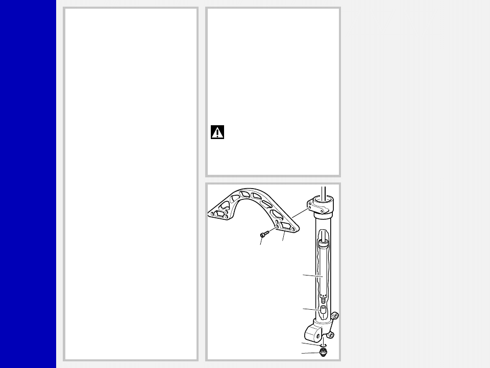
INSTALLATION
Installing the fork on a bicycle is a very
delicate operation that should be carried
out with extreme care.
A threadless steer tube is pre-installed on
the fork from the factory. It will need to be
cut to the required length for a proper fit.
Always have the installation checked at
one of our Technical Service Centers.
WARNING: “A-Head Set” head-
set/steer tube mounting and adjust-
ment must be carried out in compliance
with the headset manufacturer’s instruc-
tions. Improper installation may jeopard-
ize the safety of the rider.
After any installation always check for the
following:
– proper torque of bolts fastening stan-
chion tube onto lower crown and up-
per crown;
– proper torque of bolts fastening brake
arch onto slider
– proper torque of bolts fastening shaft to
drop out
To replace it, contact one of our Technical
Service Centers with the required tools.
WARNING: In case of improper
installation of the steer tube into the
crown, the rider might lose control of his/
her bicycle, thus jeopardizing his/her
safety.
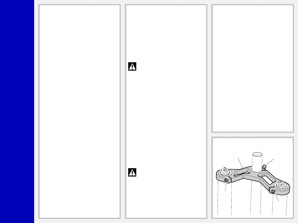
MOUNTING THE FORK
ON THE FRAME
FIG. A
Remove the upper crown (28) from steer
tube and fork legs by loosening the fasten-
ing screws (29) and (31).
Monster
T
28
28
13
C
31
29
Nm
11
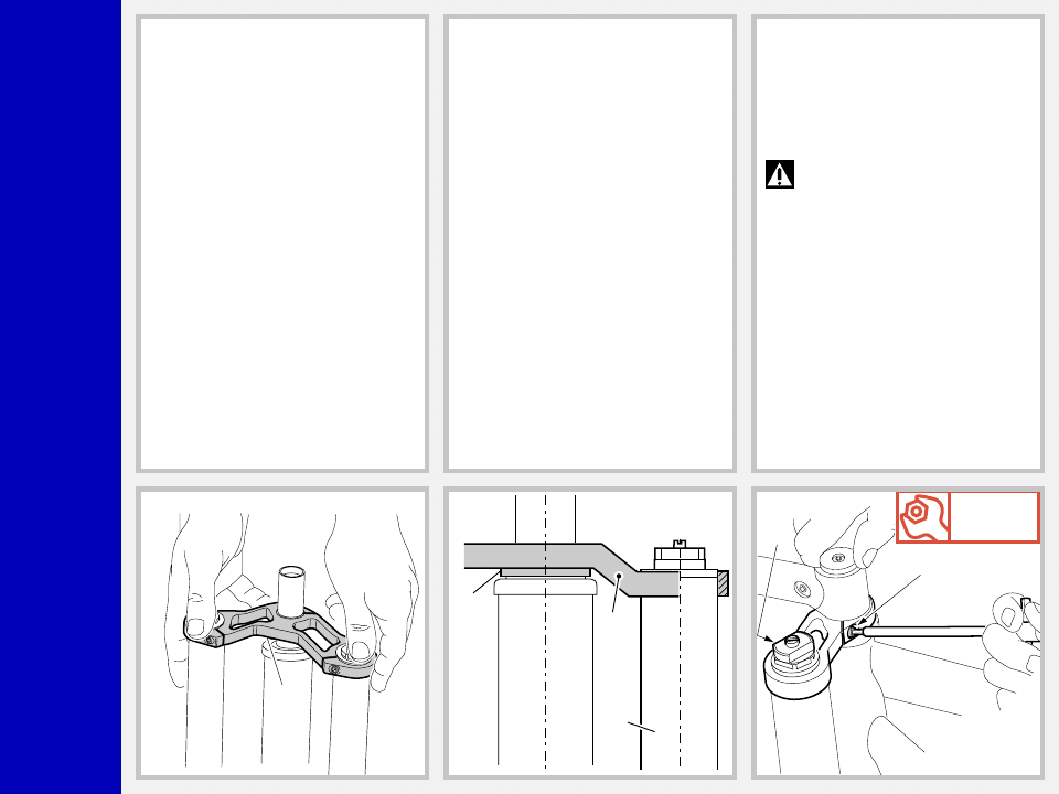
FIG. B
Assemble the fork to the frame complete
with headset. Fit the upper crown (28)
into the upper stanchions and the steer
tube.
FIG. C
The stanchions edge (13) must be aligned
with or slightly lower than the upper crown
(28). If fork legs overprotrude, fit some
spacers (C) to the plate close to the steer
tube.
In case of frame with higher steer tube, use
the optional plate supplied on request.
FIG. D
Fit the handlebar support and the “A-
Head Set” cap over the upper crown (28)
and then adjust the steering.
Now finally tighten the screws (29) and
(31) on the upper crown to 11 Nm.
WARNING: Loosen the screws
(29) and (31) on the upper crown
before adjusting the steering. Tighten the
above bolts to the required torque when
finished.
Monster
T
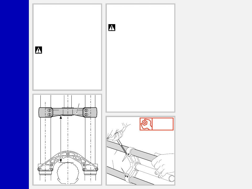
26
H
Nm
11
27
13
FIG. E
If the crown (26) position with respect to
the stanchions (13) has been changed for
any reason, adjust the original distance.
– Distance “H” between crown and tyre
edge (when inflated) should not be
lower than total travel (175 mm) + 3
mm.
WARNING: If lower Crown is
improperly matched with stan-
chions, it may touch the tyre and cause
severe injuries to the rider.
FIG. F
Tighten the 4 stanchions fastening screws
(27) onto the crown to 11 Nm.
WARNING: do not overtighten
the screws holding the stanchions
to the crown as this may distort the stan-
chions and weaken the whole structure.
Monster
T
Nm
20
23
29
Nm
6
29
23
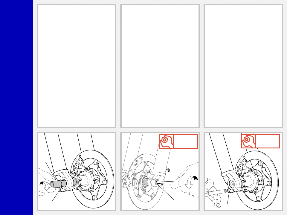
FIG. H
Tighten the wheel shaft (23) counter clock-
wise from the opposite end with a 8-mm
Allen wrench. Tighten to 20 Nm.
FIG. I
Compress the fork several times so the
sliders will become properly seated onto
the wheel shaft. Lock the pinch bolt (29)
on the r.h. lug to 6 Nm.
DISASSEMBLY
To remove the wheel proceed as follows:
– loosen the bolt (29) on the r.h. drop-
out;
– screw the wheel shaft (23) clockwise
onto the l.h. drop-out (see FIG. H);
– remove the shaft (23) from the oppo-
site side (see FIG. G).
FRONT WHEEL FIXING
IMPORTANT: for a safe and proper
performance of this fork and all related
devices, the front wheel should be abso-
lutely secured as specified in the instruc-
tions given below.
FIG. G
Insert the complete wheel assembly be-
tween the sliders and fit the wheel shaft
(23) into the slider that accommodates
the wheel shaft pinch bolt (29) from the
right hand side.
Rotate wheel shaft clockwise to start it into
the LH slider.
Monster
T
25
38
21
36
37
11-35
FORK CONFIGURATION FOR 3"
WHEEL INSTALLATION
(Fig. L)
Before you can install a 3" wheel, you will
need to:
– replace standard arch with oversized
arch (38). Reuse the fastening bolts
(25).
– Fit the spacers (36) to hydraulic car-
tridges ends (11) and (35).
– Replace the standard foot nuts with the
special nuts (37).
WARNING: Unless fork is prop-
erly configured as detailed above,
tyre will touch the arch when a 3" wheel
is installed.
DISC BRAKE SYSTEM ASSEMBLY
Assembling the brake caliper onto the
slider is a very delicate operation that
should be carried out with extreme care.
Improper assembly might overstress the
caliper supports, which might break.
This system should be assembled by spe-
cialized technicians in a position to fully
understand and properly follow the in-
structions given by the manufacturer.
Monster
T
E
2
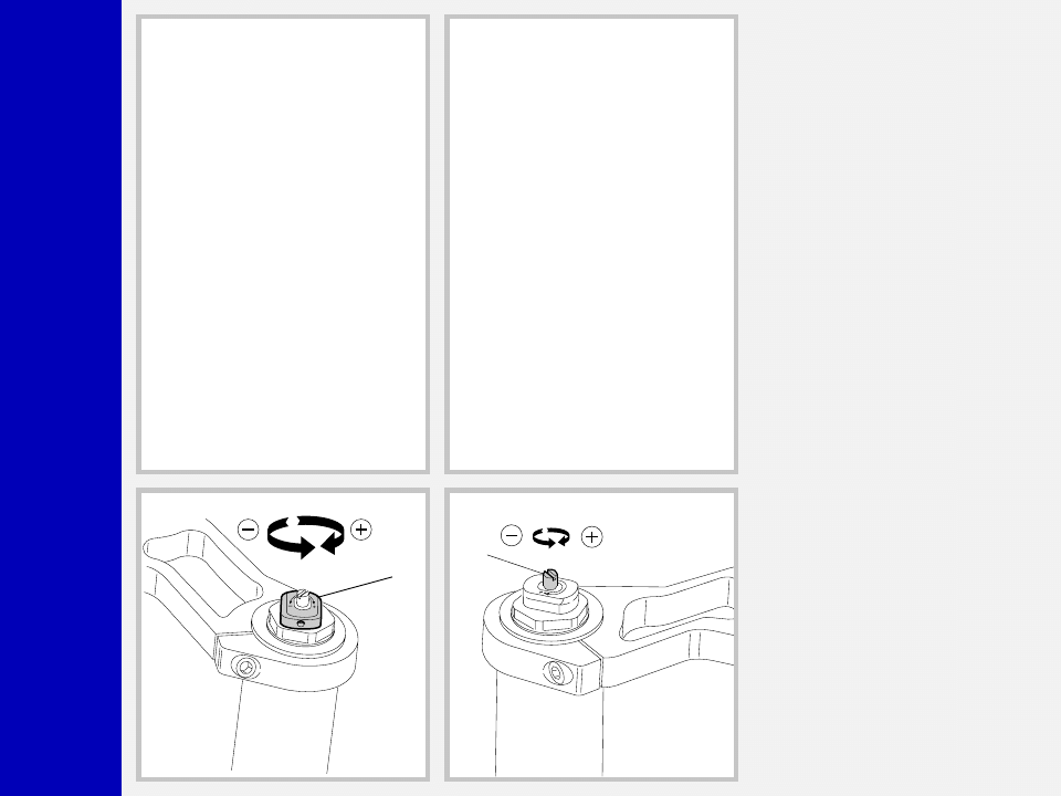
REBOUND DAMPING ADJUSTMENT
Fork legs feature an adjuster (E) for RE-
BOUND DAMPING adjustment. Turning
this adjuster clockwise into the cartridge
rod, changes the hydraulic setting of the
inner valves. In short, the amount of adjust-
ment applied on the piston in the fluid
determines the rate of compressionrebound
damping.
To adjust, always start from the minimum
damping setting, i.e. unscrew completely
counterclockwise. About 8 turns - abt. 4
mm of the adjustment - are possible.
ADJUSTMENTS
SPRING PRELOAD
The spring preload for COMPRESSION
damping can be adjusted by turning the
knob (2) on top of fork legs. From the
factory the fork is set at minimum preload,
i.e. the adjustment knob completely un-
screwed counterclockwise. However,
springs are slightly preloaded to help
counteract static loads during COMPRES-
SION. By turning the adjustment knob
clockwise, the preload is increased up to
the maximum value equal to 15 mm of
spring preload. This adjustment is essen-
tial in order to have the right fork response
for the rider’s weight and riding style.

Monster
T
▲ ▲ ▲ ▲ ▲
▲ ▲ ▲ ▲ ▲
▲ ▲ ▲ ▲ ▲
▲ ▲ ▲ ▲ ▲
▲ ▲ ▲ ▲ ▲
▲ ▲ ▲ ▲ ▲
▲ ▲ ▲ ▲ ▲
▲ ▲ ▲ ▲ ▲
▲ ▲ ▲ ▲ ▲
▲ ▲ ▲ ▲ ▲
▲ ▲ ▲ ▲ ▲
▲ ▲ ▲ ▲ ▲
▲ ▲ ▲ ▲ ▲
▲ ▲ ▲ ▲ ▲
▲ ▲ ▲ ▲ ▲
▲▲▲▲▲
▲▲▲▲▲
▲▲▲▲▲
▲ ▲ ▲ ▲ ▲
DISASSEMBLY
GENERAL
– The reference numbers given in this section relate to the components shown in the forks exploded view.
– These operations refer to the fork legs having already been removed from the crown and disassembled from the brake arch.
– Before starting any operation, please read the diagram below. It shows the quickest procedure and the exact sequence in which
it should be disassembled. Start from the part first to be disassembled and then follow the arrows to remove the remaining parts.
DISASSEMBLY DIAGRAM
GUIDE BUSHINGS AND
SEAL ASSEMBLY
CHANGE
DUST SEAL FIG. 8
SLEEVE FIG. 10
STOP RING FIG. 11
OIL SEAL FIG. 12
LOWER WASHER FIG. 13
SLIDER BUSHING FIG. 14
CIRCLIP FIG. 10
STANCHION TUBE FIG. 9
HYDRAULIC
CARTRIDGE CHANGE
FOOT NUT FIG. 6
REBOUND SPRING FIG. 7
STANCHION BUSHING
FIG. 10
HYDRAULIC CARTRIDGE
FIG. 7
SPRING CHANGE
PRELOAD KNOB FIG. 1
STANCHION TUBE CAP
FIG. 3/4
UPPER WASHER - PRELOAD
SLEEVE - SPRING - LOWER
WASHER FIG. 5
FORK OIL CHANGE
STOP RING FIG. 2
Monster
T
2
3
4
5
6
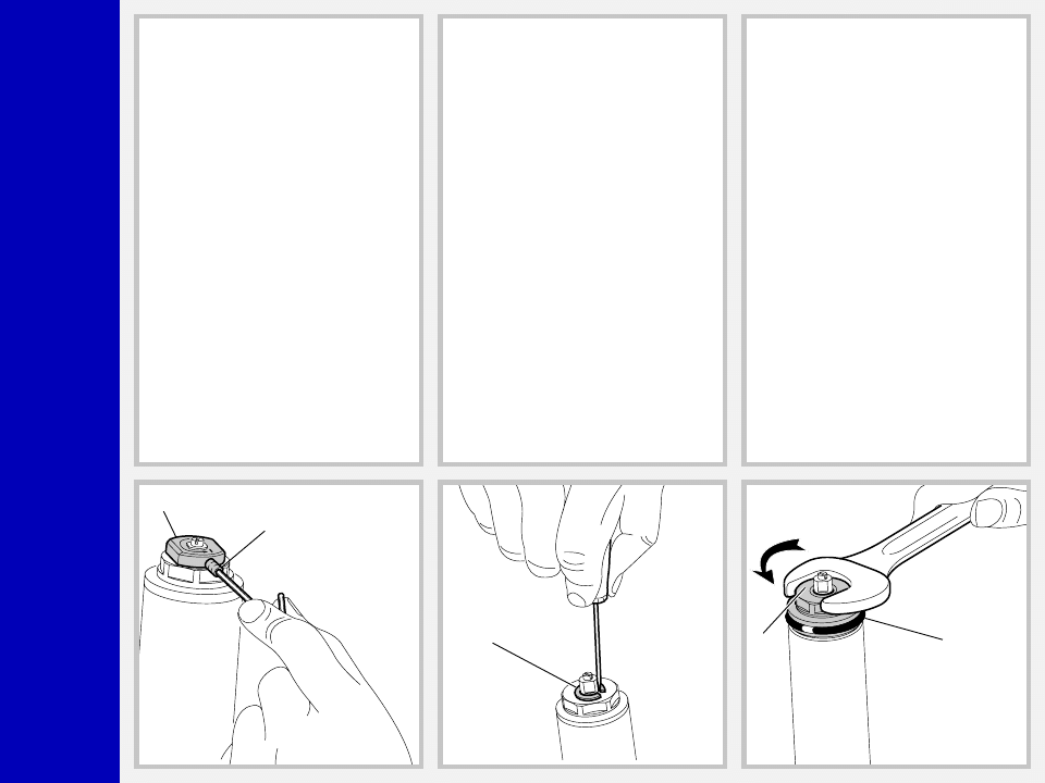
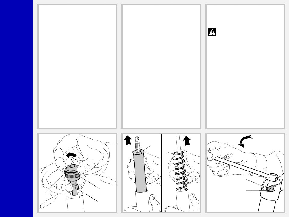
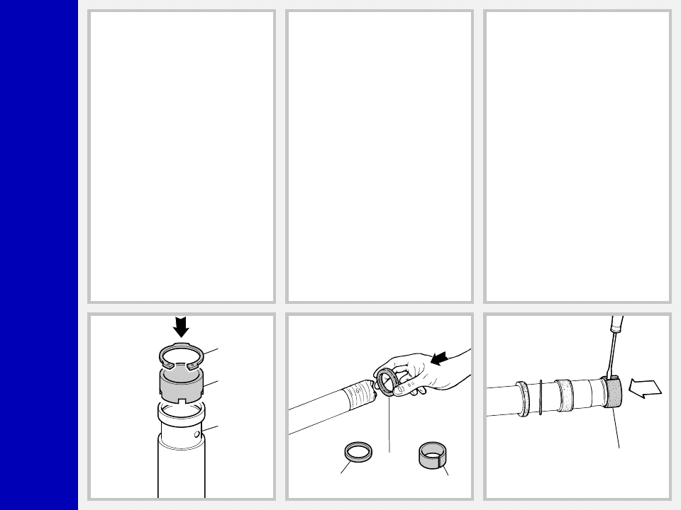
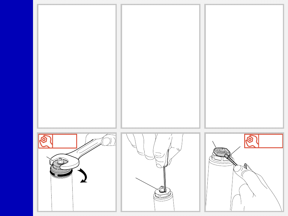
SPRING CHANGE
FIG. 1
Set knob (2) to minimum preload value.
Loosen the grub screw (3) fastening the
preload knob (2) by means of a 1.5 mm
Allen wrench. Remove grub screw from
cap assembly.
FIG. 2
Remove the stop ring (4) from the top of
the preload knob support with a small
screwdriver.
FIG. 3
Place the stanchion tube in a vice. Be sure
not to damage or dent it in the process.
Unscrew the cap (5) complete with O-ring
(6) with a 26 mm end wrench.
Monster
T
5
6
11
9
1
8
22
21
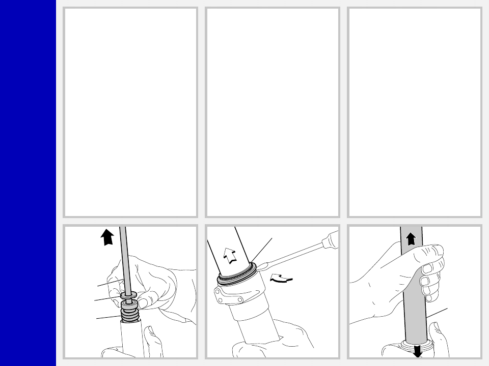
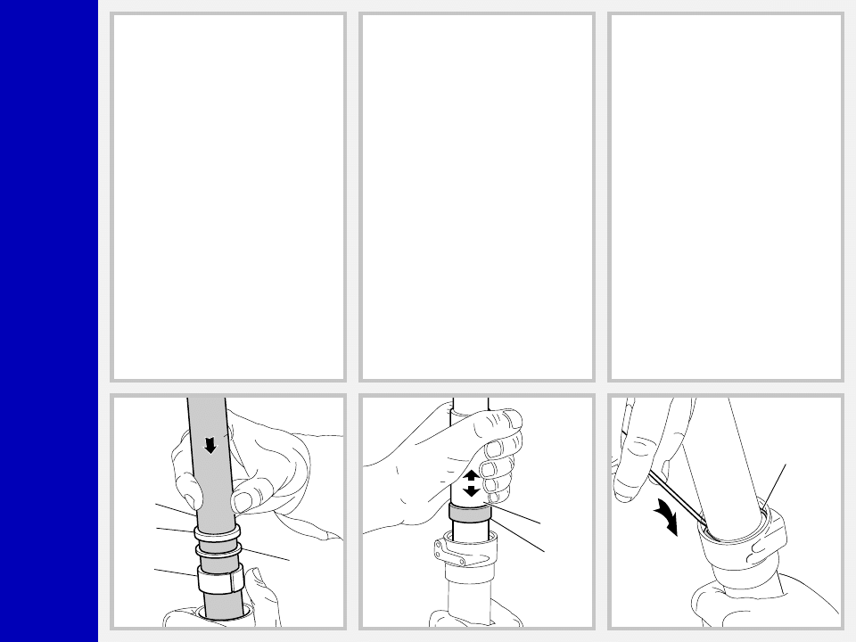
FIG. 4
Position the plunger (7, see exploded
view), into the cap, to the minimum preload
value.
Push down the stanchion tube.
Lock the check nut (11) and remove the
cap (5) from hydraulic cartridge top.
FIG. 5
Remove the upper washer (8), the preload
sleeve (1) and the spring (9).
Let all the oil drain into the fork leg. By
following this procedure, there is no need
to check the oil level. Make all necessary
changes.
HYDRAULIC CARTRIDGE CHANGE
FIG. 6
Let all the oil drain out.
WARNING: Remember to always
recycle any used oil.
To change the fork leg oil follow the
procedure as described in REASSEMBLY
from FIG. 24 to FIG. 29.
Turn the fork leg upside-down and un-
screw the foot nut (22) complete with O-
ring (21) by the use of a 15 mm socket
wrench.
Monster
T
11
12
8A
14
13
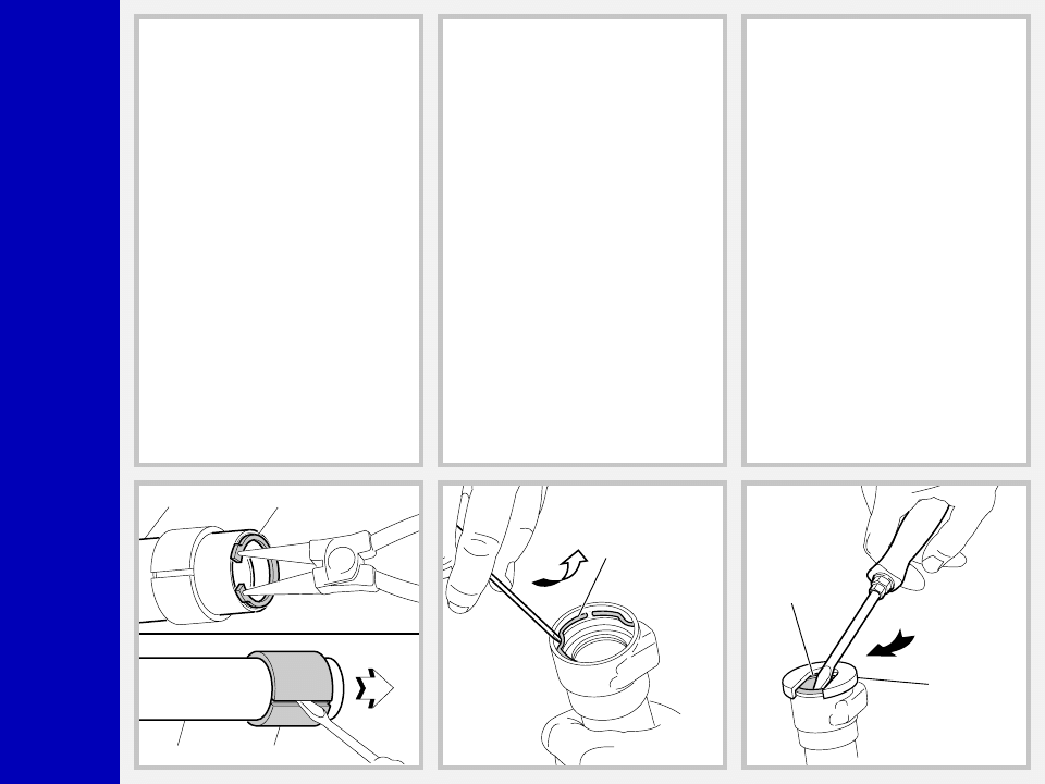
FIG. 7
Pull the hydraulic cartridge (11) complete
with lower washer (8A) and rebound
spring (12) out of the stanchion tube.
Replace the whole hydraulic cartridge.
GUIDE BUSHINGS AND SEAL
ASSEMBLY CHANGE
FIG. 8
Use a small screwdriver and remove the
dust seal (14) from the top of the slider.
Pull the dust seal out of the stanchion tube.
FIG. 9
Pull the stanchion tube (13) completely
out of the slider.
Pull strongly to overcome the resistance of
the guide bushing of the stanchion tube to
slide through the slider bushing.
IMPORTANT: the seal unit will be per-
manently damaged by the guide bushing.
Always change the oil seals after the
above procedure.
Monster
T
13
32
13
34
15
16
A
FIG. 10
A sleeve (33) is located inside the stan-
chion tube. Remove the outer snap ring
(32) to remove the sleeve (33). Should
the guide bushing (34) be damaged,
remove it from the stanchion (13) insert-
ing a small screwdriver into the bushing
slot.
FIG. 11
Remove the stop ring (15) from the slider
by placing the screwdriver bit in one of the
three openings on the stop ring and care-
fully lifting the ring out of place.
IMPORTANT: when removing the stop
ring, make sure not to damage its seat.
FIG. 12
Fit the slider protector (A) onto the slider
and remove the oil seal (16) with the help
of a large slot screwdriver.
IMPORTANT: when removing the oil
seal, make sure not to damage its seat.
Once removed, the oil seals should not be
used again.
Monster
T
17
18
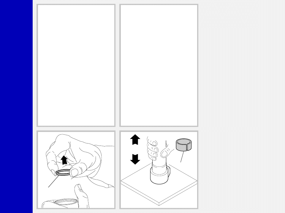
FIG. 13
Remove the upper washer (17) from the
slider.
FIG. 14
To remove the guide bushing (18), beat
powerfully the slider edge on a wooden
surface. Perform this operation with ex-
treme care and try to keep the slider
perpendicular to the wooden surface.
Monster
T
32
33
13
16
17
18
34
REASSEMBLY
CAUTION: before reassembling, all metal
components should be washed carefully
with inflammable and biodegradable sol-
vent and dried with compressed air.
FIG. 15
Fit the sleeve (33), with its completely
open side facing outwards, on the stan-
chion edge (13). Fit the outer snap ring
(32). Make sure it is fully seated in the
tube.
FIG. 16
Stick some adhesive tape onto the stan-
chion bottom (13) to protect it. Insert the
oil seal (16), duly lubricated, the bushing
washer (17) and the slider guide bushing
(18) into the stanchion. Remove the adhe-
sive tape and clean the stanchion.
FIG. 17
Insert the bit of the flat screwdriver into the
guide bushing slot (34) to fit it on the
stanchion tube. Ease it into the tube seat
by hand.
Monster
T
18
16
13
17
16
B
15
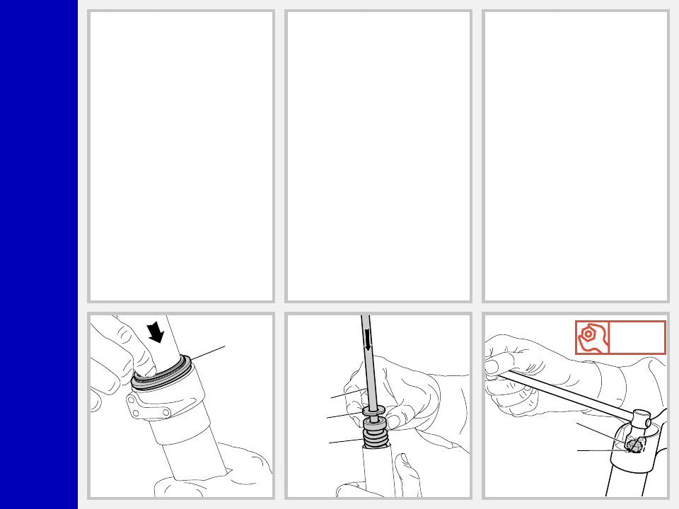
FIG. 18
Gently insert the stanchion tube (13) into
the slider from the bushing side.
Fit the guide bushing (18) and the bush-
ing washer (17) into the slider seat by
hand.
FIG. 19
Press the oil seal (16) into place until it
touches the lower washer (17) by using
the seal press (B).
FIG. 20
Insert the stop ring (15) making sure it is
properly seated into place.
Use buffer (B) to properly seat the ring
into the slider.
Monster
T
14
11
12
8A
Nm
12
22
21
FIG. 21
Lubricate the dust seal (14) and insert it
into the top of the slider.
Fit it into the slider seat.
HYDRAULIC CARTRIDGE
FIG. 22
Fit the rebound spring (12) and the lower
washer (8A) into the hydraulic cartridge.
Insert the complete hydraulic cartridge
(11) with the stanchion tube pressed fully
down.
FIG. 23
Grease the O-ring (21) on the foot nut
(22) and screw the nut onto the hydraulic
cartridge thread.
Tighten to 12 Nm.
Pump stanchion up and down several
times to make sure it slides properly through
the stroke.
Monster
T
100
9
1
8
10
5
6
11
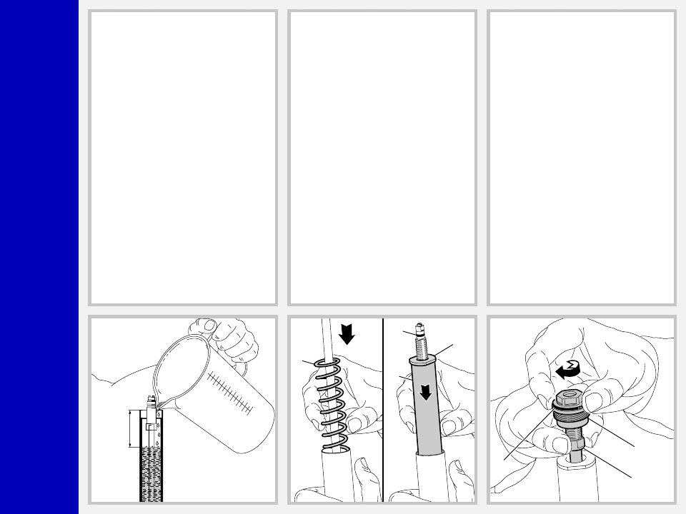
HOW TO FILL WITH OIL
FIG. 24
Pour the oil little by little when the stan-
chion tube is fully down and then pump
the cartridge rod (11) up and down so as
to have a better filling. Cartridge is full
when no air is detected when pumping, in
the fully compressed position. Check that
oil level is 100 mm from the top of the
stanchion tube in each leg.
SPRING AND CAP
FIG. 25
Fit the spring (9), the preload sleeve (1)
and the upper washer (8) into the stan-
chion tube.
Lubricate the O-ring (10) on the top of the
preload knob support and the O-ring (6)
on the cap (5).
FIG. 26
Position the plunger (7, see exploded
view), into the cap, to the minimum preload
value.
Screw the complete plug (5) fully onto the
cartridge rod (11).
Monster
T
5
Nm
12
4
Nm
1,5
2
3
FIG. 27
Lift the stanchion tube and fit the plug (5)
by hand. Place the stanchion tube in vice.
Make sure not to damage or squeeze it.
Tighten to 12 Nm.
FIG. 28
Fit the stop ring (4) of the preload knob
support and make sure it is fitted properly
into its seat.
FIG. 29
Fit the preload knob (2), secure it on the
support and tighten the Allen bolt (3) to
1.5 Nm.
Fit the brake arch to the fork leg, and then
install fork legs into crown and upper
crown as specified in section “INSTALLA-
TION”.
Monster
T
B
A
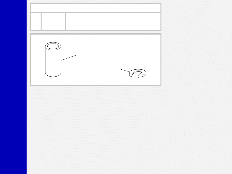
SPECIFIC MARZOCCHI TOOLS
R e f .
I t e m .
Description and use
A
536064 GG
Slider protector: to remove oil seal from the slider
B
R 5083 AC
Oil seal press: to press oil seal into the slider
Wyszukiwarka
Podobne podstrony:
2000 monster t service manual
2001 z5 coil service manual
hplj 5p 6p service manual vhnlwmi5rxab6ao6bivsrdhllvztpnnomgxi2ma vhnlwmi5rxab6ao6bivsrdhllvztpnnomg
Oberheim Prommer Service Manual
Korg SQ 10 Service Manual
MAC1500 service manual
Kyocera Universal Feeder UF 1 Service Manual
Proview RA783 LCD Service Manual
indesit witp82euy Service Manual
Glow Worm installation and service manual Hideaway 70CF UIS
Proview PZ456 LCD Service Manual
Glow Worm installation and service manual Ultimate 50CF UIS
ewm2000 service manual
Glow Worm installation and service manual Ultimate 60CF UIS
Proview SH770I LCD Service Manual
M23 Service Manual
Glow Worm installation and service manual Glow micron 60
Konica Minolta QMS 7115, 7118 Service Manual
więcej podobnych podstron