TUTORIAL SERIES FOR
VERSION 8
TUTORIAL 6
LATHE - 3D GEOMETRY; FACE, ROUGH AND FINISH;
FACE CONTOUR; CROSS
CONTOUR; C-AXIS CONTOUR; FACE
DRILL; CROSS DRILL; CUTOFF

TUTORIAL 6
Page 6-1
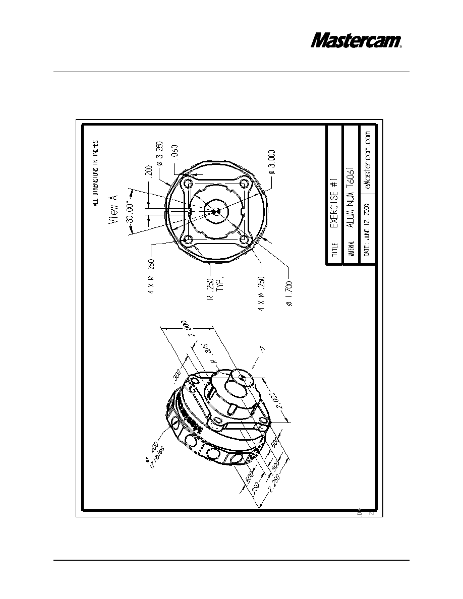
Objectives:
To design a 3 dimensional drawing by:
!"Creating the 2D geometry in different construction planes at different construction depths.
!"Using Xform, Translate to create the 3D wireframe
To establish Job setup settings:
!"Stock size.
!"Tool offsets.
!"Tool clearance.
!"Material of the part.
!"Feed calculation.
To create a 2 dimensional lathe toolpaths consisting of:
!"Face cutting the part.
!"Rough machining the part.
!"Finish machining the part.
!"Cutoff the part.
To create C-axis milling toolpaths consisting of:
!"Face contour
!"Cross contour
!"C-axis contour
!"Face drilling
!"Cross drilling
To check the toolpath using Mastercams Verify verification module by:
!"Running the Verify function to machine the part on the screen.
TUTORIAL 6
Page 6-2
TUTORIAL 6
Page 6-3
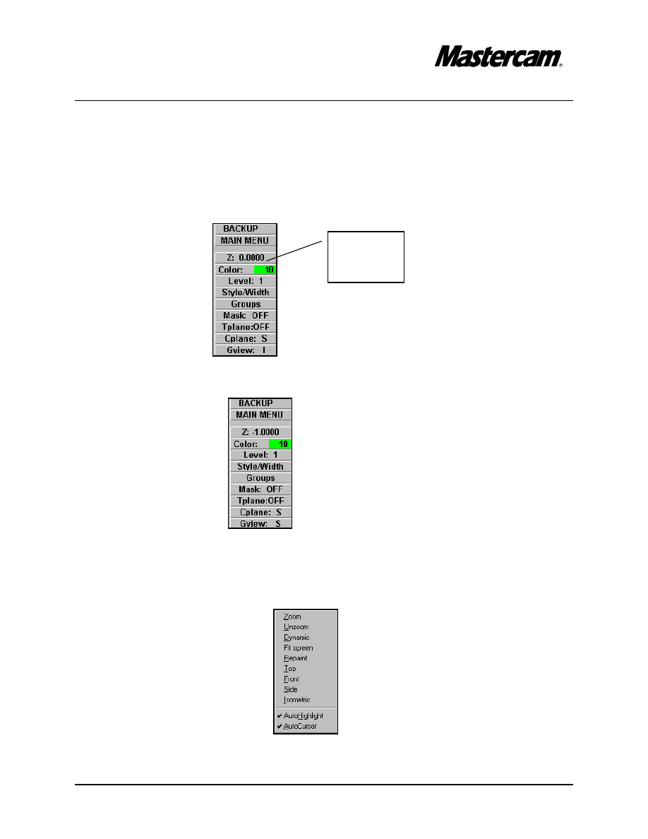
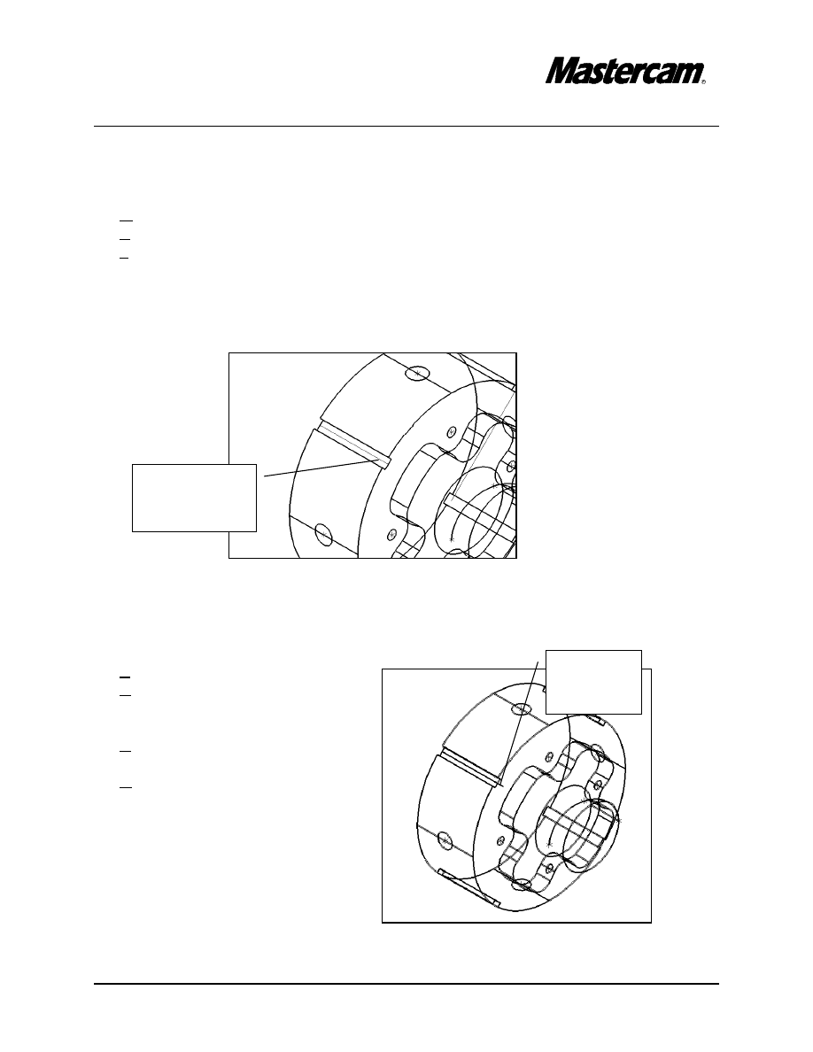
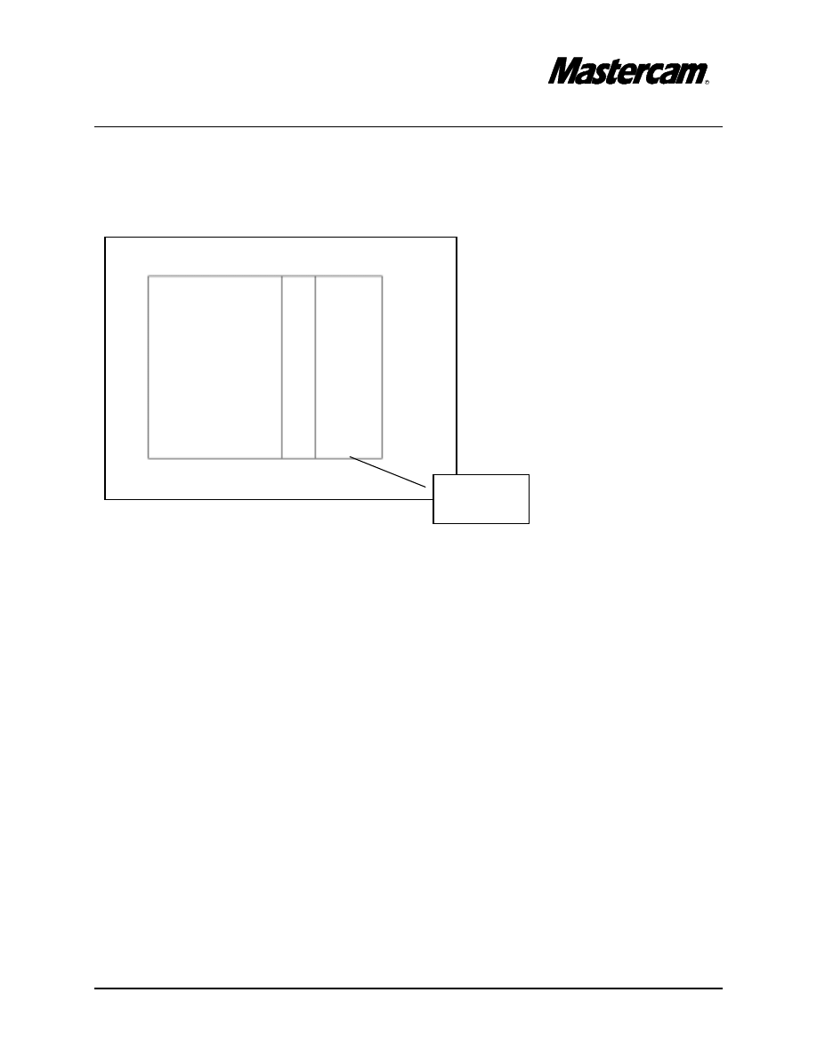
Select Cplane
here
Select Gview
here
GEOMETRY CREATION
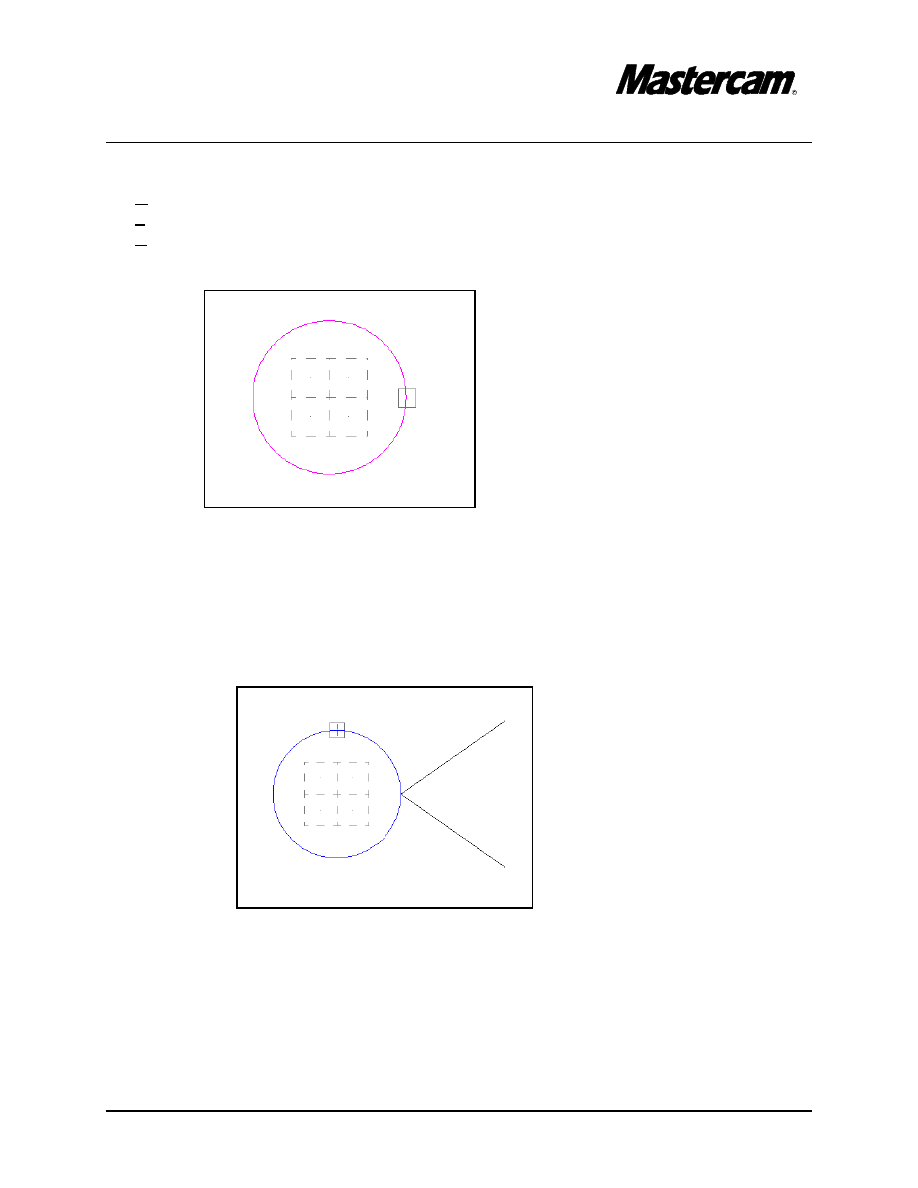
STEP 1:
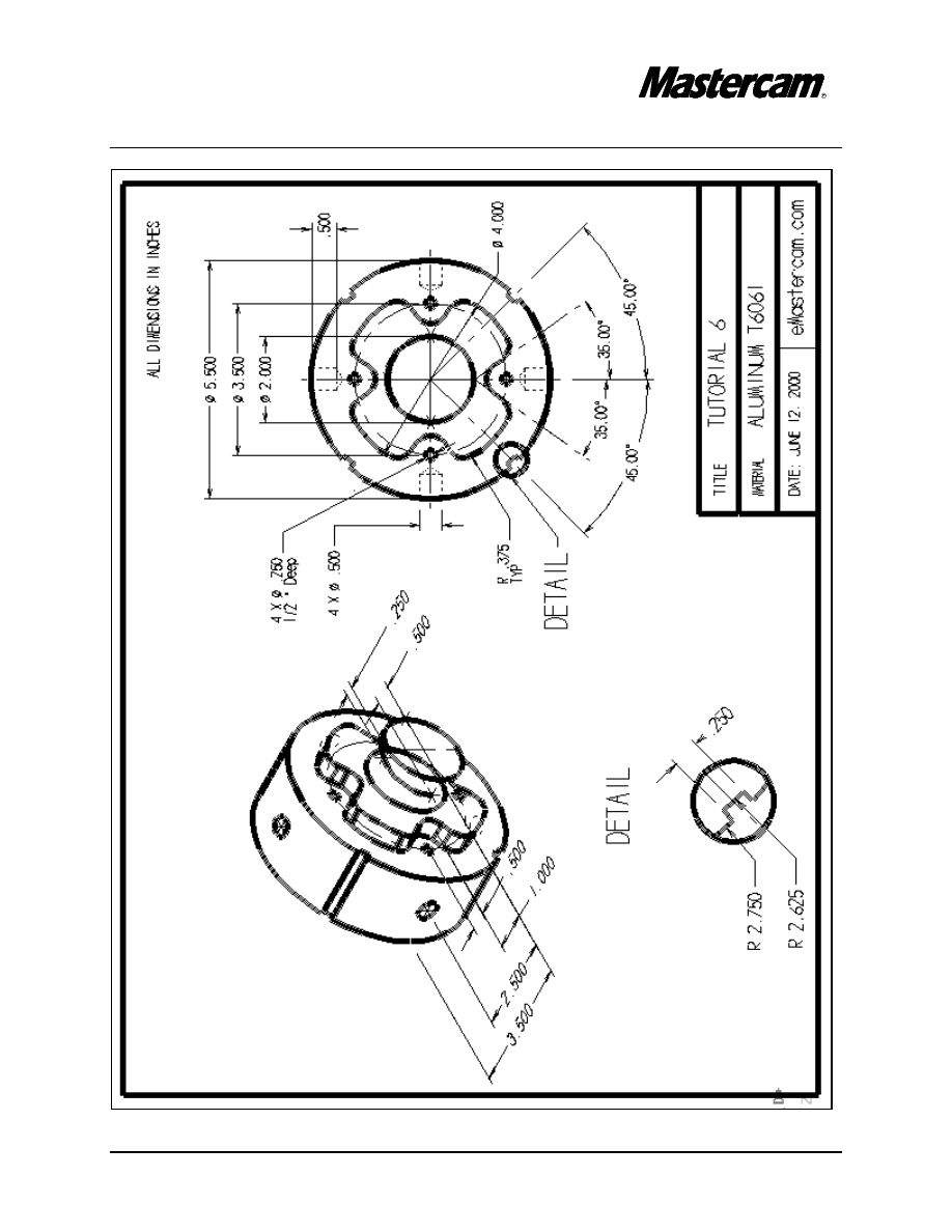
CREATE THE 1“ DIAMETER CYLINDER.
Change the Construction plane and the Graphic view to Side.
MAIN MENU
#"Cplane
#"Side
#"Gview
#"Side
MAIN MENU
#"
Create
#"
Arc
#"
Circ pt + dia
#"
[ Enter the diameter ] 2
#"
Origin
#"
Press Esc to exit the command
MAIN MENU
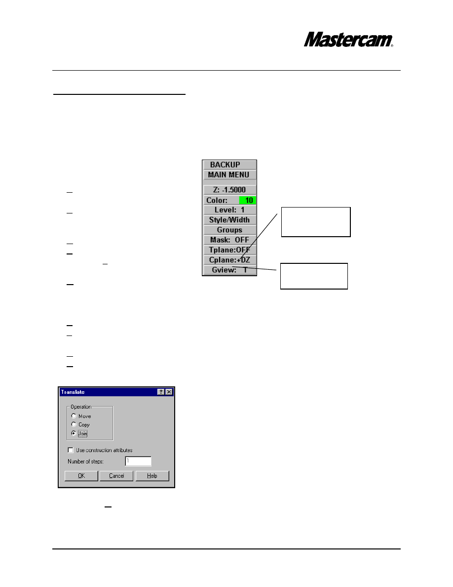
#"
Xform
#"
Translate
#"
Select the arc.
#"
Done
#"
Rectang
#"
[ Enter the translation vector ]: Z -1
#"Select OK button.
TUTORIAL 6
Page 6-4
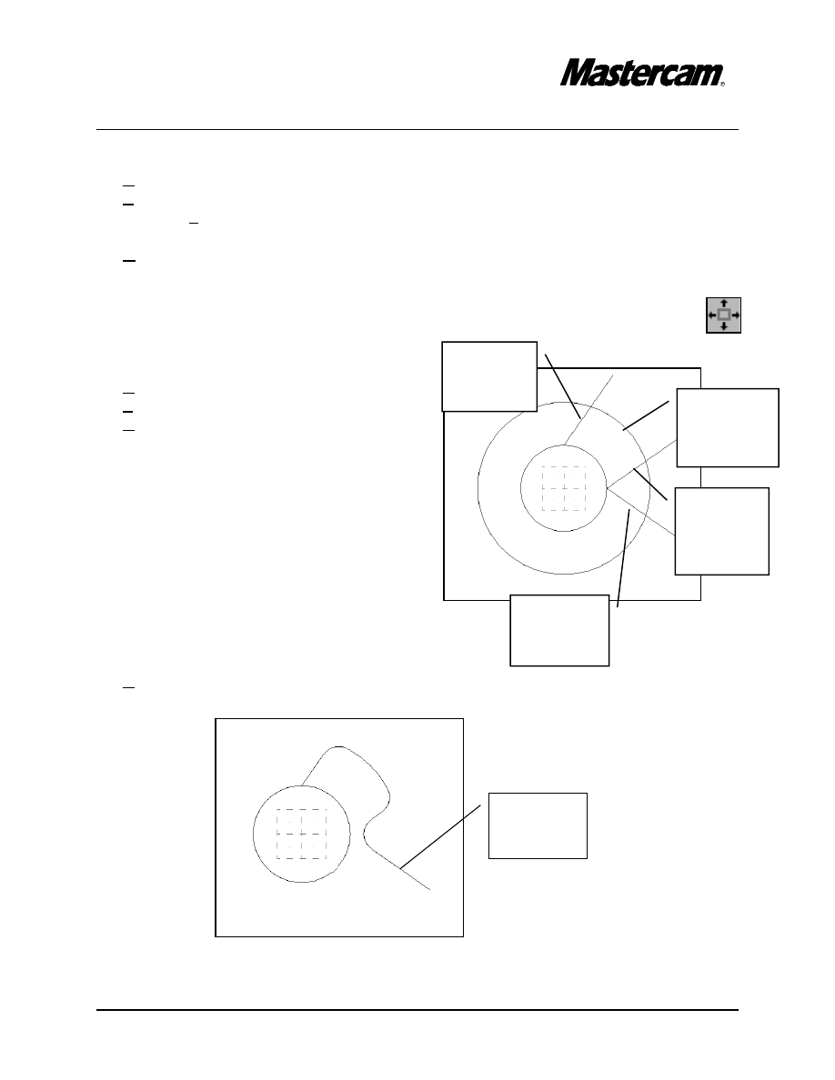
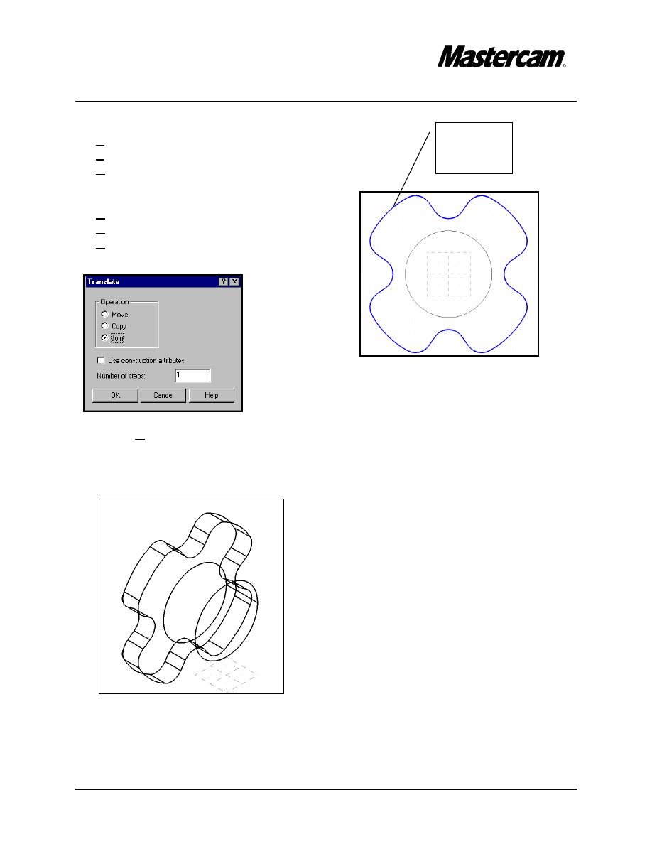
STEP 2:
CREATE THE 3D WIREFRAME OF THE CONTOUR WITH FILLET RADII
OF .375“.
Change the construction depth to Z-1
#"Select Z from the secondary menu as shown in the following picture.
#"[ Select point for new construction depth ]: -1
Make sure that Autocursor is enabled.
#"
Right-mouse click in the middle of the screen.
#"
AutoCursor should have the check mark in front as shown in the following dialog
box.
#"
Press Esc to exit the dialog box.
Select Z
here
TUTORIAL 6
Page 6-5
MAIN MENU
#"Create
#"Line
#"Polar
#"[Specify an endpoint]: Select the Endpoint of the arc as shown in the picture.
#"
[ Enter the angle in degrees ]: 35
#"
[ Enter the line length ]: 2
#"[Specify an endpoint]: Select the same Endpoint of the arc as shown in the previous
picture.
#"
[ Enter the angle in degrees ]: -35
#"
[ Enter the line length ]: 2
#"[Specify an endpoint]: Select the Quadrant of the arc as shown in the picture.
#"
[ Enter the angle in degrees ]: 90-35
#"
[ Enter the line length ]: 2
TUTORIAL 6
Page 6-6
Select
Entity A
here
Select
Entity B
here
Select
Entity C
here
Select
Entity D
here
MAIN MENU
#"
Create
#"
Arc
#"
Circ pt + dia
#"
[ Enter the diameter ] 4
#"
Origin
#"
Press Esc to exit the command
#"
Using the toolbar located at the top of the screen, fit the drawing to the
screen.
MAIN MENU
#"
Create
#"
Fillet
#"
Radius
#"
[Enter the fillet radius]: .375
#"
[ Select an entity ]: Select entity C
#"
[ Select an other entity ]: Select entity A
#"
[ Select an entity ]: Select entity A
#"
[ Select an other entity ]: Select entity B
#"
[ Select an entity ]: Select entity B
#"
[ Select an other entity ]: Select entity D
MAIN MENU
#"
Delete
#"
Select the line as shown in the following picture.
Delete this
line
TUTORIAL 6
Page 6-7
Select the
contour
here
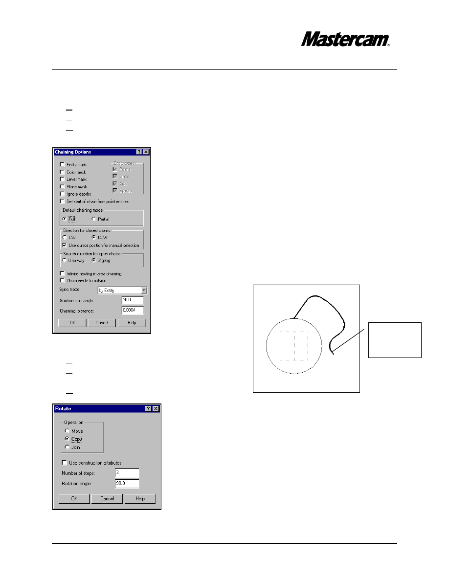
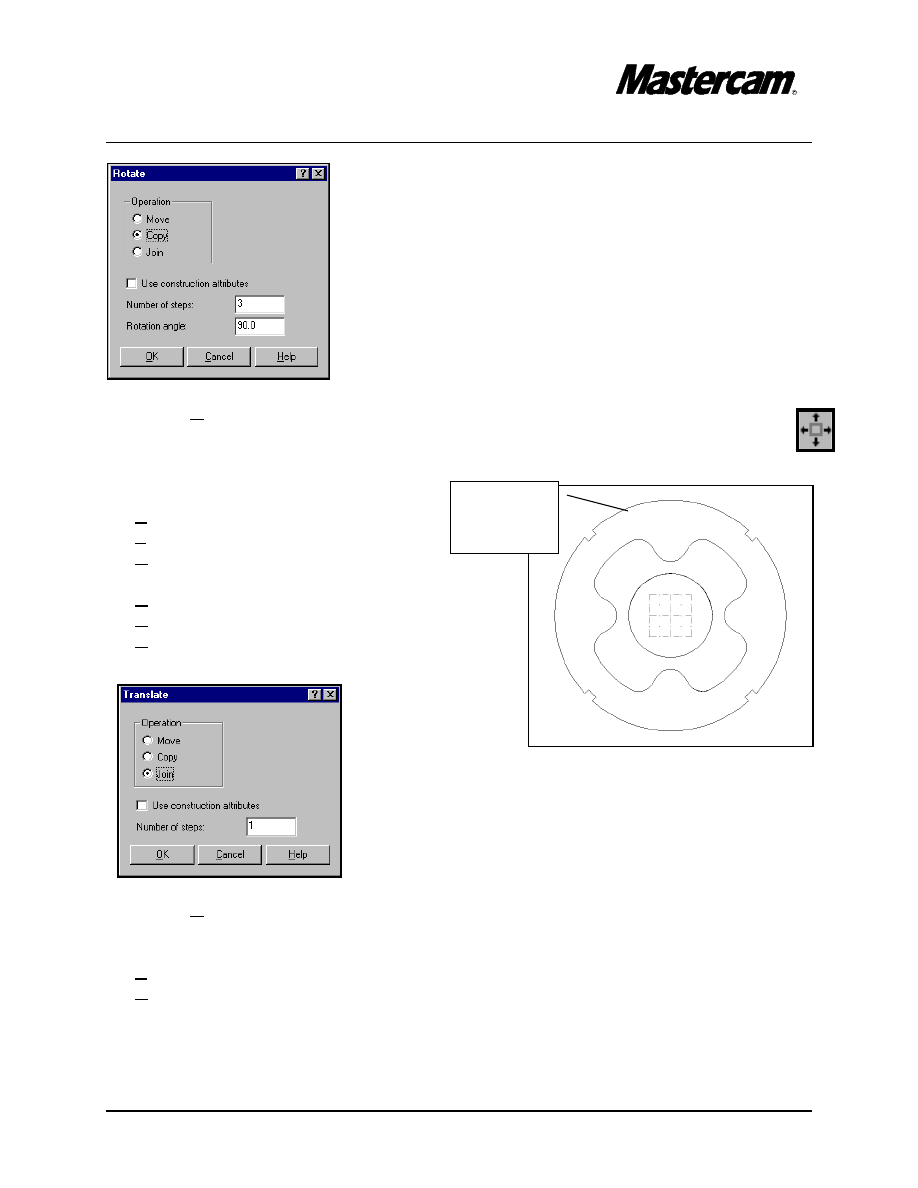
MAIN MENU
#"Xform
#"Rotate
#"Chain
#"Options
#"Set the default chaining mode to Full
#"Select the contour as shown in the picture.
#"Done
#"Done
#"[ Enter the point to rotate about]
#"Origin
TUTORIAL 6
Page 6-8
#"
Select OK button.
#"
Using the toolbar located at the top of the screen, fit the drawing to the screen.
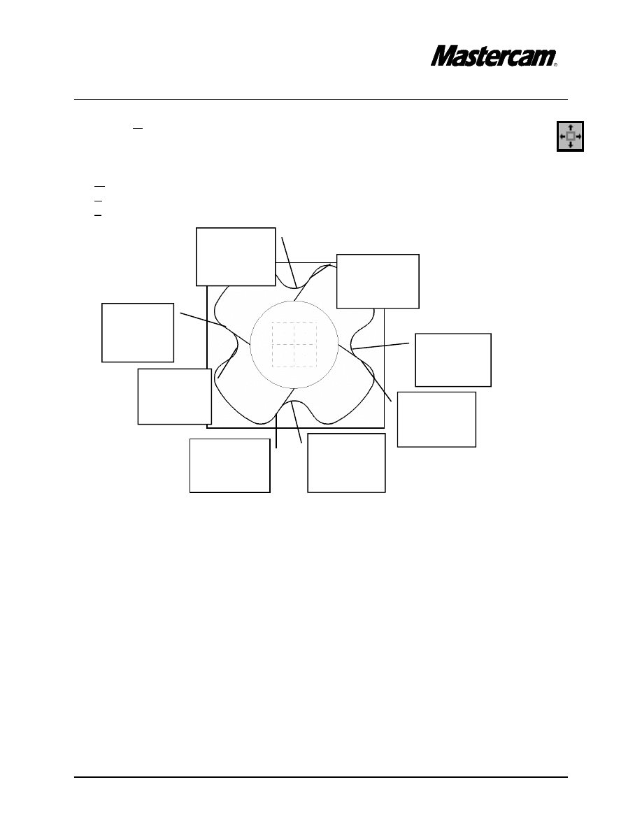
MAIN MENU
#"
Modify
#"
Trim
#"
2 entities
#"
[ Select entity to trim ]: Select Entity A
#"
[ Select the entity to trim to]:Select Entity B
#"
[ Select entity to trim ]: Select Entity C
#"
[ Select the entity to trim to]:Select Entity D
#"
[ Select entity to trim ]: Select Entity E
#"
[ Select the entity to trim to]:Select Entity F
#"
[ Select entity to trim ]: Select Entity G
#"
[ Select the entity to trim to]:Select Entity H
Select
Entity A
here
Select
Entity B
here
Select
Entity C
here
Select
Entity D
here
Select
Entity E
here
Select
Entity F
here
Select
Entity G
here
Select
Entity H
here
TUTORIAL 6
Page 6-9
Select this
contour
MAIN MENU
#"Xform
#"Translate
#"Chain
#"Select the contour as shown in the picture.
#"Done
#"Done
#"Rectang
#"[ Enter the translation vector]: Z-.5
#"
Select OK button.
Change the Graphic View to Isometric.
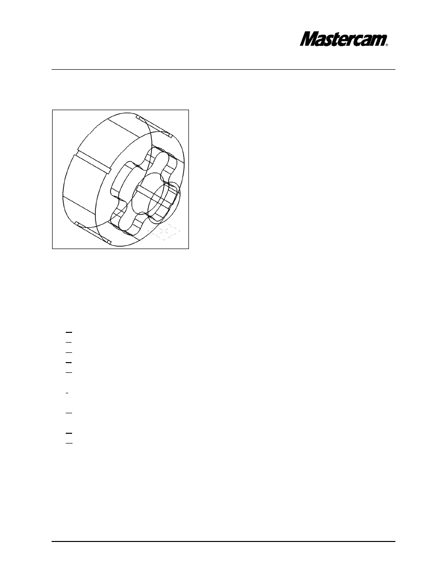
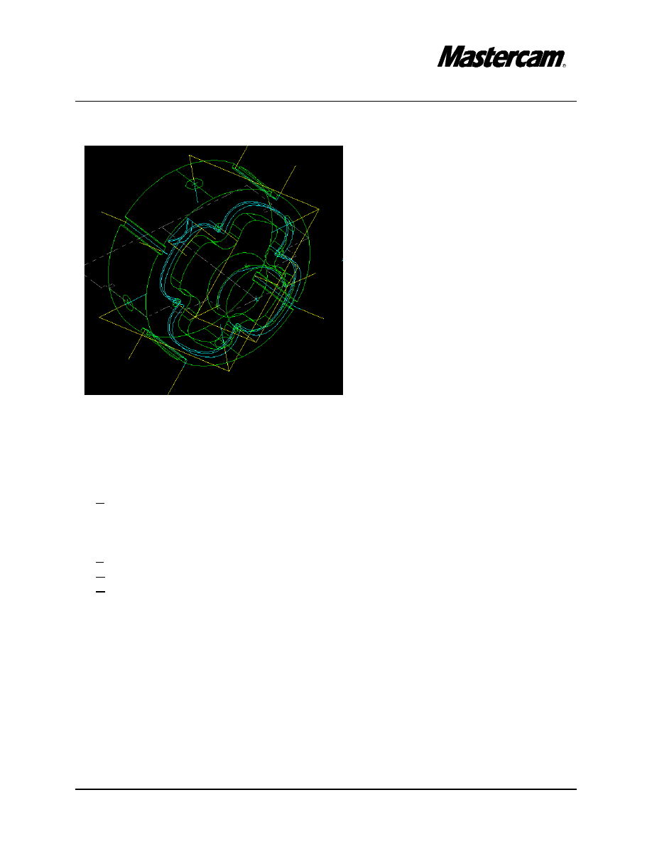
The part should look as shown in the following picture.

TUTORIAL 6
Page 6-10
STEP 3:
CREATE THE 5.5“ DIAMETER CYLINDER.
Change the Gview and the Cplane back to Side.
Change the construction depth to Z-1.5 as shown at pag 6-3
MAIN MENU
#"
Create
#"
Arc
#"
Polar
#"
Center pt
#"
[Enter the center point]:
#"
Origin
#"
[ Enter the radius]: 2.75
#"
[ Enter the initial angle]: 0
#"
[ Enter the final angle]: 90
#"
Using the toolbar located at the top of the screen, fit the drawing to the screen.
#"
[Enter the center point]:
#"
Origin
#"
[ Enter the radius]: 2.625
#"
[ Enter the initial angle]: 0
#"
[ Enter the final angle]: 90
MAIN MENU
#"Create
#"Line
#"Polar
#"[Specify an endpoint]:
#"
Origin
#"
[ Enter the angle in degrees ]: 45
#"
[ Enter the line length ]: 3
MAIN MENU
#"Create
#"Line
#"Parallel
#"Side/dist
#"[ Select line]: Select the 45 deg. line
#"[ Indicate the offset direction]: Select a point at the left side of the line
#"[ Parallel line distance]: .125
TUTORIAL 6
Page 6-11
Select
Entity A
Select
Entity B
Select
Entity C
#"[ Select line]: Select the 45 deg. line
#"[ Indicate the offset direction]: Select a point at the right side of the line
#"[ Parallel line distance]: .125
MAIN MENU
#"
Modify
#"
Trim
#"
Divide
#"
[ Select curve to divide]:Select Entity A
#"
[ Select the first dividing curve]: Select Entity B
#"
[ Select the second dividing curve]: Select Entity C
BACKUP
#"
3 entities
#"
[ Select the first entity to trim ]: Select Entity A
#"
[ Select the second entity to trim ]: Select Entity B
#"
[ Select the entity to trim to ]: Select Entity C
Select
Entity A
here
Select
Entity B
here
Select
Entity C
here
TUTORIAL 6
Page 6-12
Select this
contour
Delete this
Entity
BACKUP
#"
1 entities
#"
[ Select the first entity to trim ]: Select Entity A
#"
[ Select the entity to trim to ]: Select Entity B
#"
[ Select the first entity to trim ]: Select Entity C
#"
[ Select the entity to trim to ]: Select Entity D
MAIN MENU
#"
Delete
#"
Select the 45 deg line as shown in the
following picture.
MAIN
MENU
#"Xform
#"Rotate
#"Chain
#"Select the contour as shown in the
picture.
#"Done
#"Done
#"[ Enter the point to rotate about]
#"Origin
Select
Entity A
here
Select
Entity C
here
Select
Entity B
here
Select
Entity D
here
TUTORIAL 6
Page 6-13
Select the
contour
here
#"
Select OK button.
#"
Using the toolbar located at the top of the screen, fit the drawing to the screen.
MAIN MENU
#"Xform
#"Translate
#"Chain
#"Select the contour as shown in the picture.
#"Done
#"Done
#"Rectang
#"[ Enter the translation vector]: Z-2
#"
Select OK button.
MAIN MENU
#"Screen
#"Clr colors
TUTORIAL 6
Page 6-14
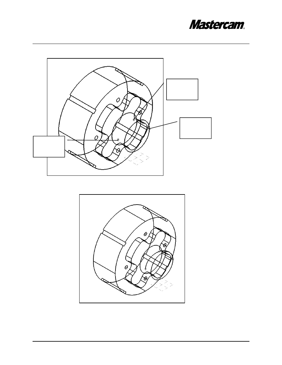
Change the Graphic View to Isometric and fit the geometry to the screen.
The part should look as shown in the following picture.
STEP 4:
CREATE THE CENTER POINTS OF THE .25“ DIAMETER HOLES.
Change The Cplane and the Gview back to Side.
MAIN MENU
#"
Create
#"
Point
#"
Next menu
#"
Bolt circle
#"
Radius
#"
[ Radius =]: 3.5/2
#"
Incr angle
#"
[ Incremental angle =]: 90
#"
Num of pts
#"
[ Number of points =]: 4
#"
Do it
#"
Origin
#"
Press Esc to exit the command.
$For machining purpose you only need the center points. You can create the arcs
following the next steps.

TUTORIAL 6
Page 6-15
MAIN MENU
#"
Create
#"
Arc
#"
Circ pt + dia
#"
[ Enter the diameter ] .25
#"
Select the points that you have just created to establish the center points of the
arcs.
#"
Press Esc to exit the command.
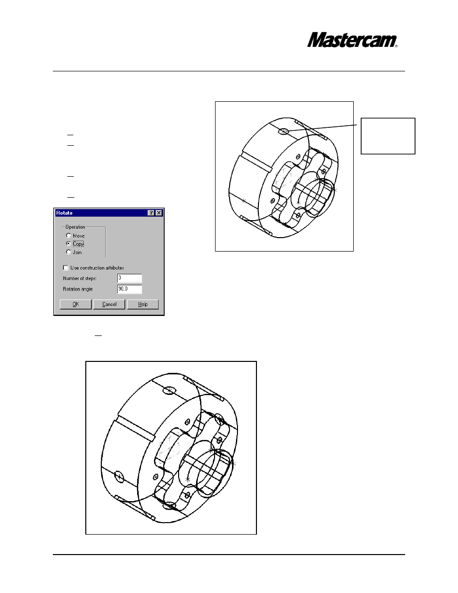
STEP 5:
CREATE THE 3 POINTS AND THE 3D ARC THAT GOES THROUGH
THE POINTS.
MAIN MENU
#"
Create
#"
Point
#"
Position
#"
[ Specify a point]: 1,0,0
#"
[ Specify a point]: 0,1,-.25
#"
[ Specify a point]: -1,0,-.5
Change the Graphic View to Isometric and Cplane to 3D.
MAIN MENU
#"
Create
#"
Arc
#"
3 points
#"
[ Enter the first point ]: Select Point 1
#"
[ Enter the second point ]: Select Point 2
#"
[ Enter the third point ]: Select Point 3
TUTORIAL 6
Page 6-16
The part should look as shown in the following picture.
Select
Point 1
Select
Point 2
Select
Point 3

TUTORIAL 6
Page 6-17
STEP 6:
CREATE THE CENTER POINTS OF THE .25“ DIAMETER HOLES.
Change the Gview and the Cplane to Side.
Change the construction depth to Z -2.5
MAIN MENU
#"
Create
#"
Point
#"
Next menu
#"
Bolt circle
#"
Radius
#"
[ Radius =]: 5.5/2
#"
Incr angle
#"
[ Incremental angle =]: 90
#"
Num of pts
#"
[ Number of points =]: 4
#"
Do it
#"
Origin
#"
Press Esc to exit the command.
For machining purpose you only need the center points. You can create the arcs
following the next steps.
Change the Cplane to Top.
Change the construction depth to Z 2.75
MAIN MENU
#"
Create
#"
Arc
#"
Circ pt + dia
#"
[ Enter the diameter ] .5
#"
Type the centerpoint coordinates: -2.5, 0
#"
Press Esc to exit the command.
TUTORIAL 6
Page 6-18
Select this
arc
Change the Cplane to Side.
MAIN
MENU
#"Xform
#"Rotate
#"Select the arc as shown in the
picture.
#"Done
#"[ Enter the point to rotate about]
#"Origin
#"
Select OK button.
The final part should look as shown in the following picture.
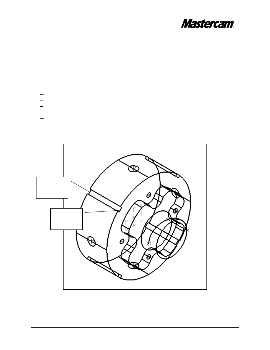
TUTORIAL 6
Page 6-19
For machining purpose we have to create extra geometry.
STEP 7:
CREATE THE CENTER LINES OF THE .25“ WIDTH CHANELS.
Change the Cplane to 3D.
MAIN MENU
#"
Create
#"
Line
#"
Endpoints
#"
[ Specify the first endpoint]:
#"
Midpoint
#"
Select Entity A
#"
[ Specify the second endpoint]:
#"
Midpoint
#"
Select Entity B
Select
Entity A
here
Select
Entity B
here
TUTORIAL 6
Page 6-20
Select this
line
MAIN MENU
#"
Modify
#"
Extend
#"
Length
#"
[ Enter the length to extend]: .2
#"
[ Select a curve near the endpoint to extend]: Select Entity A close to one endpoint
as shown in the following picture.
Change the Cplane to Side.
MAIN
MENU
#"Xform
#"Rotate
#"Select the line as shown in the
picture.
#"Done
#"[Enter the point to rotate about]
#"Origin
Select entity A
close to this
endpoint
TUTORIAL 6
Page 6-21
Select
Cplane
here
Select
Gview
here
#"
Select OK button.
MAIN MENU
#"Screen
#"Clr colors
STEP 8:
CREATE HALF OF THE 2D GEOMETRY.
#"
Change the Cplane to + dZ.
#"
Cplane
#"
Next Menu
#"
3 +dz
#"
Change the Gview to Top
TUTORIAL 6
Page 6-22
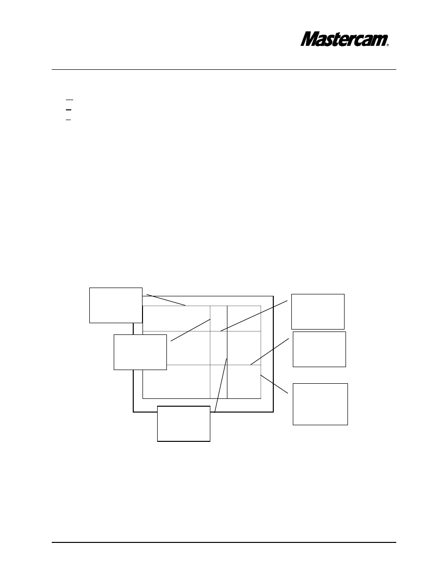
Select
Level here
#"
Change the main Level 1 to Level 2
#"
Level
#"
Change the Main Level Number to 2
#"
Make Level 1 invisible by disable the check mark next to Level 1 as shown in the
above screen shot.
#"
Select OK button to exit.
#"
Select F3 key to repaint the screen.
$Note that the 3D geometry that you just created is invisible.
Change the
Main level
number to 2
Click here to
make level1
invisible
TUTORIAL 6
Page 6-23
Select
Entity A
Select
Entity B
Change the construction plane to Z 0.
MAIN MENU
#"Create
#"Rectangle
#"1 point
#"
Select OK button
#"
Origin
#"
Press Esc to exit the command
MAIN MENU
#"Create
#"Line
#"Parallel
#"Side/dist
#"[ Select line]: Select Entity A
#"[ Indicate the offset direction]: Select a point at the left side of the line
#"[ Parallel line distance]: 1
#"[ Select line]: Select Entity B
#"[ Indicate the offset direction]: Select a point at the
rigth side of the line
#"[ Parallel line distance]: 2
Select this Point
Placement
TUTORIAL 6
Page 6-24
#"[ Select line]: Select Entity C
#"[ Indicate the offset direction]: Select a point above the line
#"[ Parallel line distance]: 1
#"[ Select line]: Select Entity C
#"[ Indicate the offset direction]: Select a point above the line
#"[ Parallel line distance]: 2
Select
Entity C
TUTORIAL 6
Page 6-25
MAIN MENU
#"Modify
#"Trim
#"2 entities
#"[ Select the entity to trim ]: Select Entity A
#"
[ Select the entity to trim to]: Select Entity B
#"
[ Select the first entity to trim ]: Select Entity B
#"
[ Select the second entity to trim ]: Select Entity C
#"
[ Select the first entity to trim ]: Select Entity C
#"
[ Select the second entity to trim ]: Select Entity D
#"
[ Select the first entity to trim ]: Select Entity D
#"
[ Select the second entity to trim ]: Select Entity E
#"
[ Select the first entity to trim ]: Select Entity E
#"
[ Select the second entity to trim ]: Select Entity F
Select
Entity A
here
Select
Entity B
here
Select
Entity C
here
Select
Entity D
here
Select
Entity E
here
Select
Entity F
here
TUTORIAL 6
Page 6-26
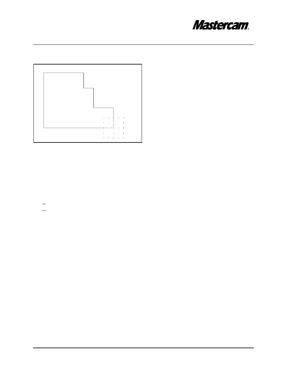
The part should look like in the following picture.
#"
Using the toolbar located at the top of the screen, fit the drawing to the screen.
STEP 9:
SAVE THE FILE.
MAIN MENU
#"File
#"Save
#"Save this file under “C-axis_1”
TUTORIAL 6
Page 6-27
TOOLPATH CREATION
STEP 10:
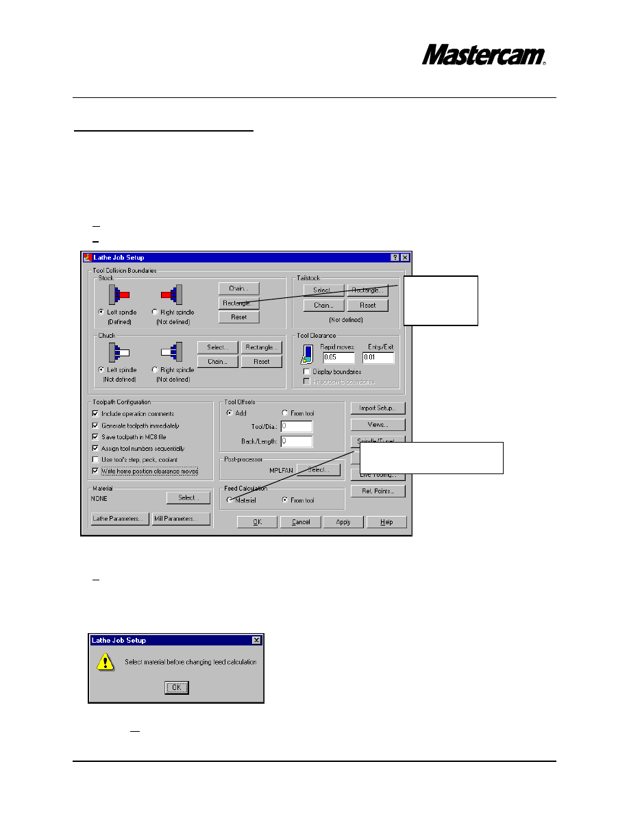
SET UP THE STOCK TO BE MACHINED
MAIN MENU
#"
Toolpaths
#"
Job Setup
#"
Under Stock select Rectangle.
#"
2 points
#"
[Enter the lower left corner:] 0,-5
#"
[Enter coordinates:] 5.8,0.15
#"
Select the radio button in front of material as shown in the picture above.
#"
Select OK button.
2. Select Material here
1. Select
Rectangle
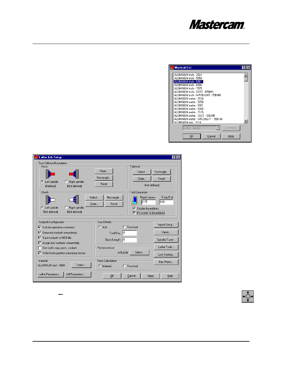
TUTORIAL 6
Page 6-28
#"
From Lathe Material List choose Aluminum 6061.
#"
Select OK.
#"The Lathe Job Setup parameters screen should
look as shown in the picture below.
#"Select OK button.
#"Using the toolbar located at the top of the screen, fit the drawing to the screen.
TUTORIAL 6
Page 6-29
Select the
endpoint
STEP 11:
FACE THE PART.
Refer to Lathe Tutorial #1 in the Mastercam Lathe Training Tutorials page 1-7 to 1-8.
The manual is available at your local Mastercam dealer or at
http://www.emastercam.com/resources/
STEP 12:
ROUGH THE PART.
Refer to Lathe Tutorial #1 in the Mastercam Lathe Training Tutorials page 1-9 to 1-10.
STEP 13:
FINISH THE PART.
Refer to Lathe Tutorial #1 in the Mastercam Lathe Training Tutorials page 1-11 to 1-13.
STEP 14:
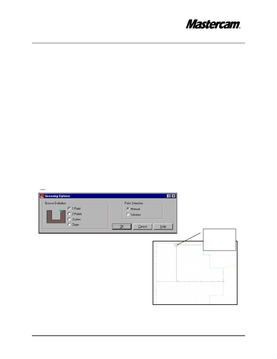
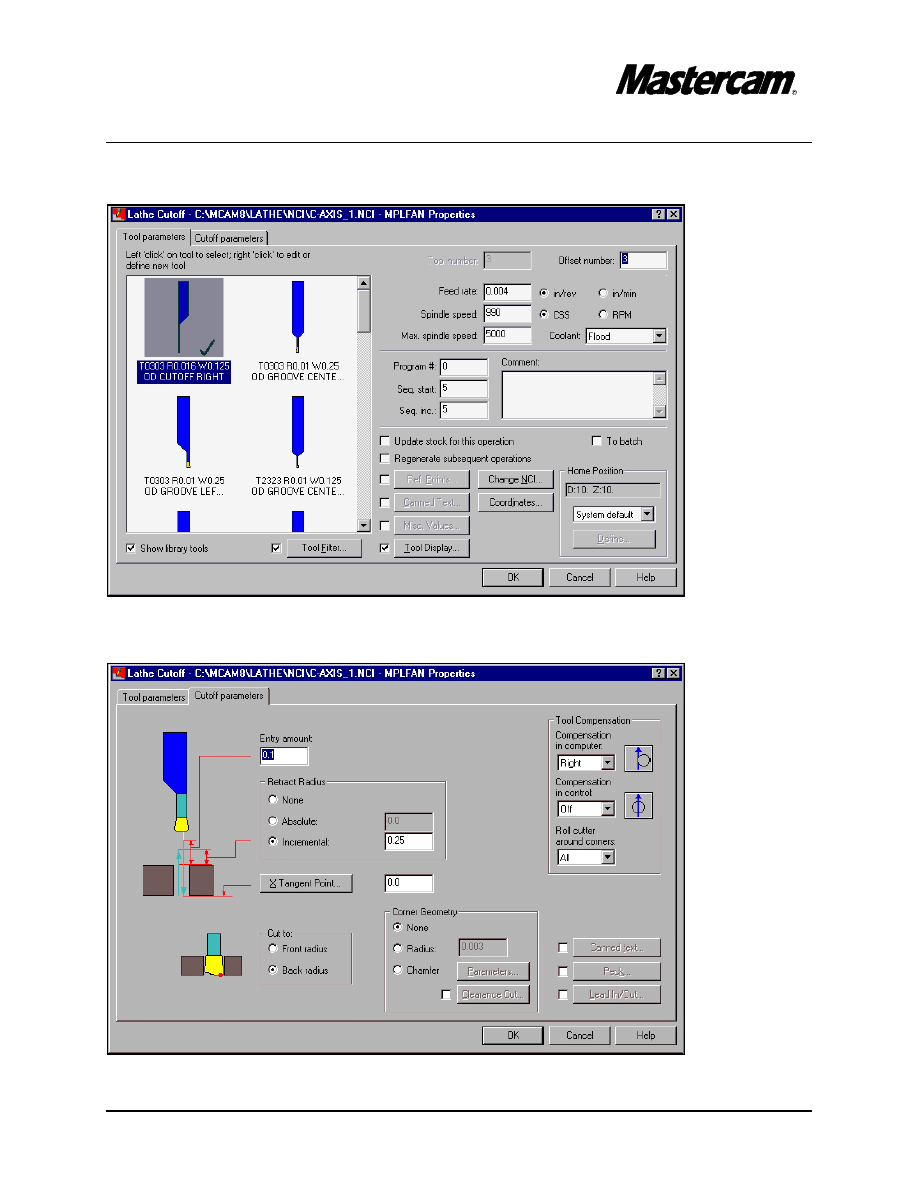
CREATE A GROOVE FOR THE RELIEF CUT OFF AREA TO AVOID
INTERRUPTED CUTS.
#"
Groove
#"
Select OK button.
#"
[Select points]:
#"
Select the point as shown in the picture.
#"
Press Esc button to exit checking.
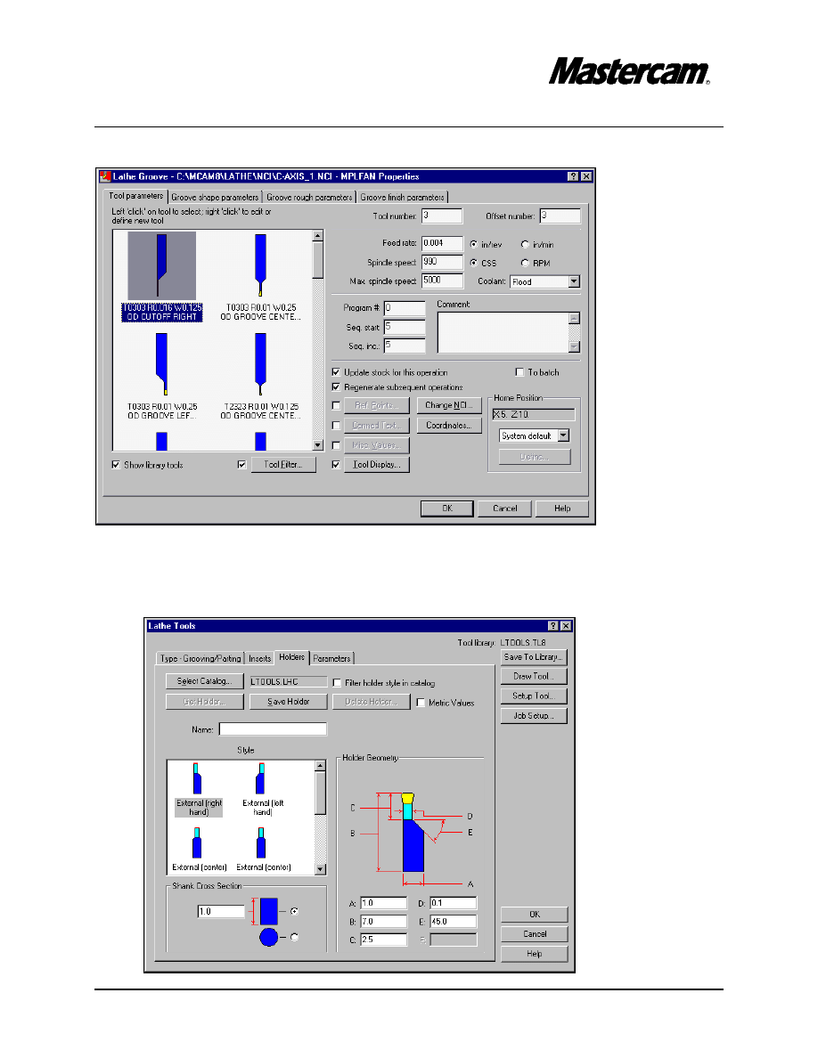
TUTORIAL 6
Page 6-30
#"
Double-mouse click on the selected tool to edit.
#"
Select Holders page and change C value to 2.5 as shown in the following screen
shot.
TUTORIAL 6
Page 6-31
#"
Select OK button to exit tool definition.
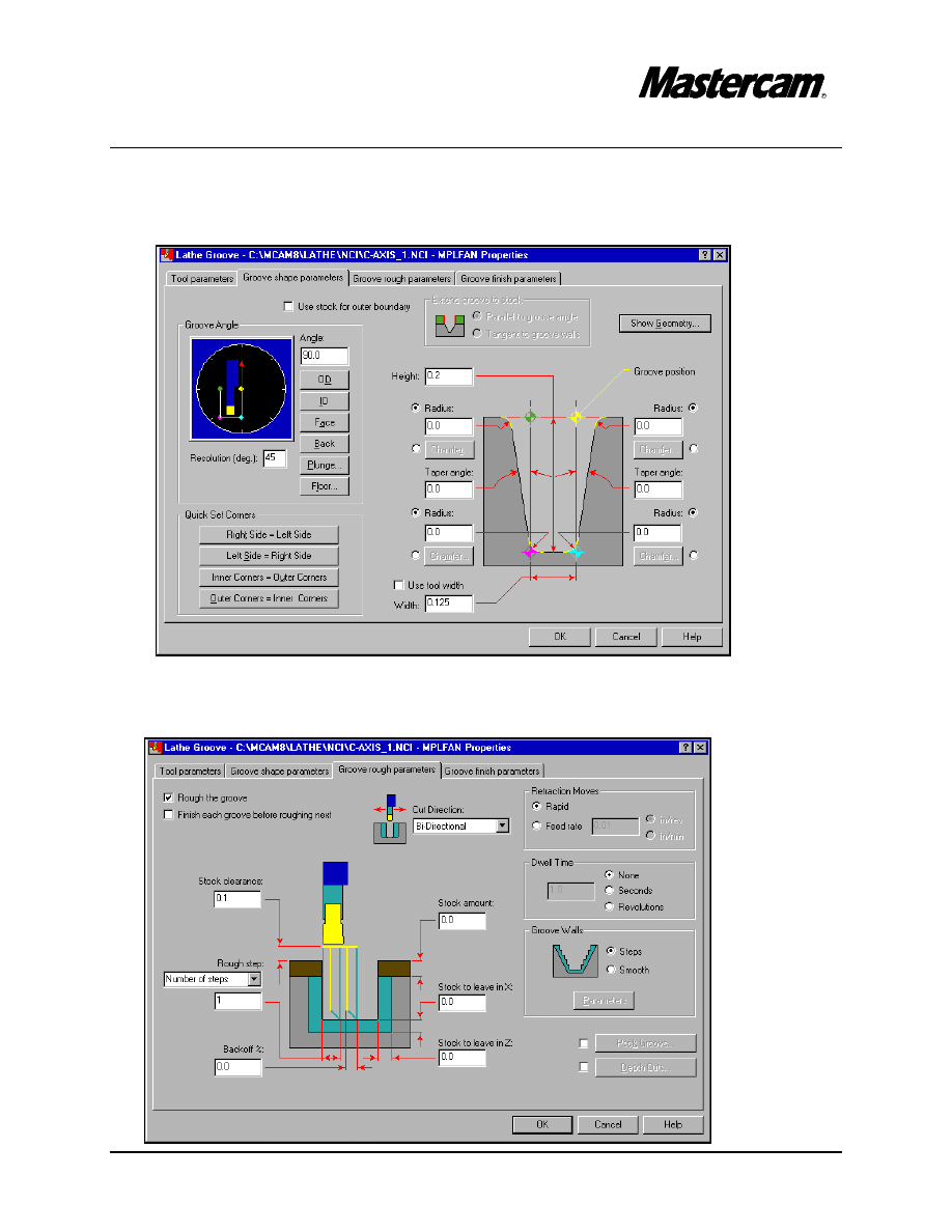
#"
Select Grove shape parameters and change the height and the width as shown
below.
#"
Select the Groove rough parameters page and make all necessary changes as
shown in the screen shot.
TUTORIAL 6
Page 6-32
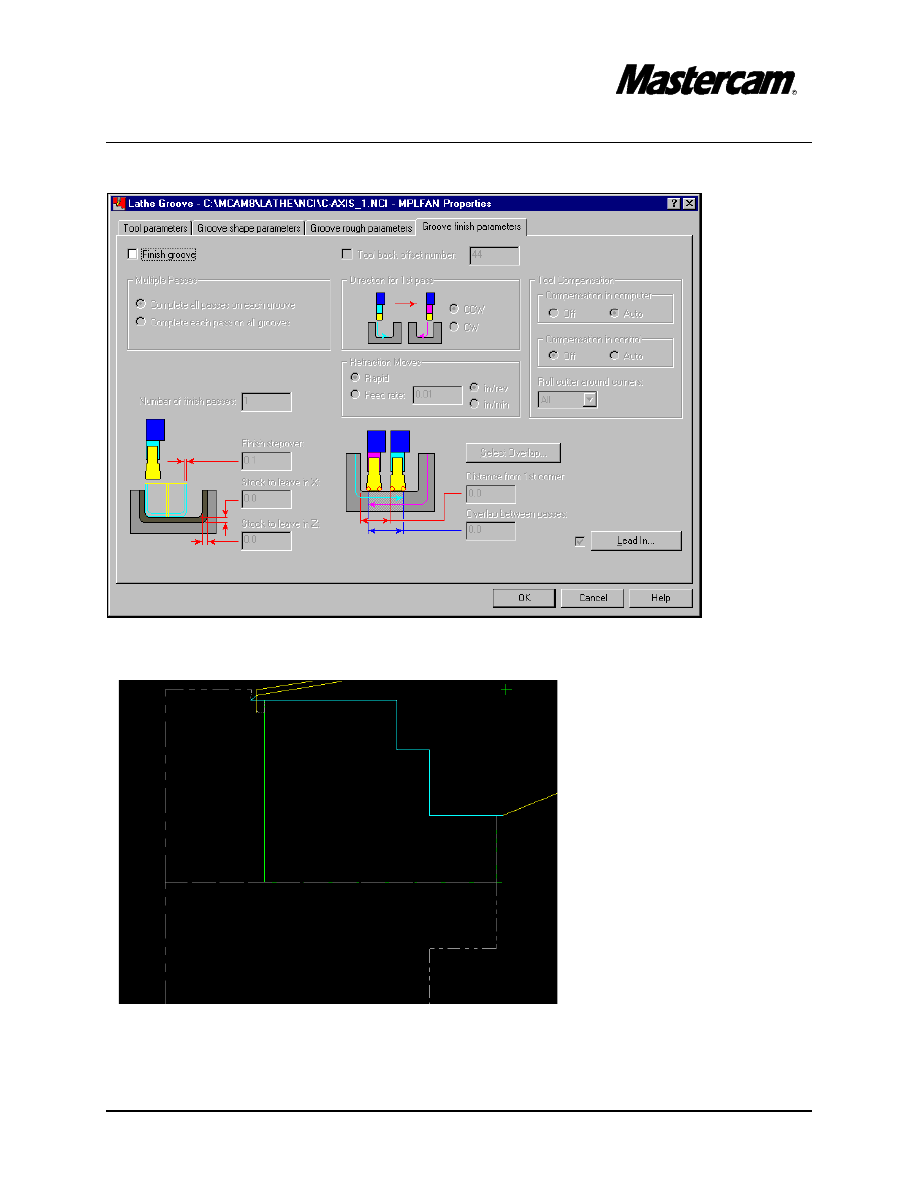
#"
Select Groove finish parameter and disable the box in front of Finish groove.
#"
Select OK button to exit.
TUTORIAL 6
Page 6-33
STEP 15:
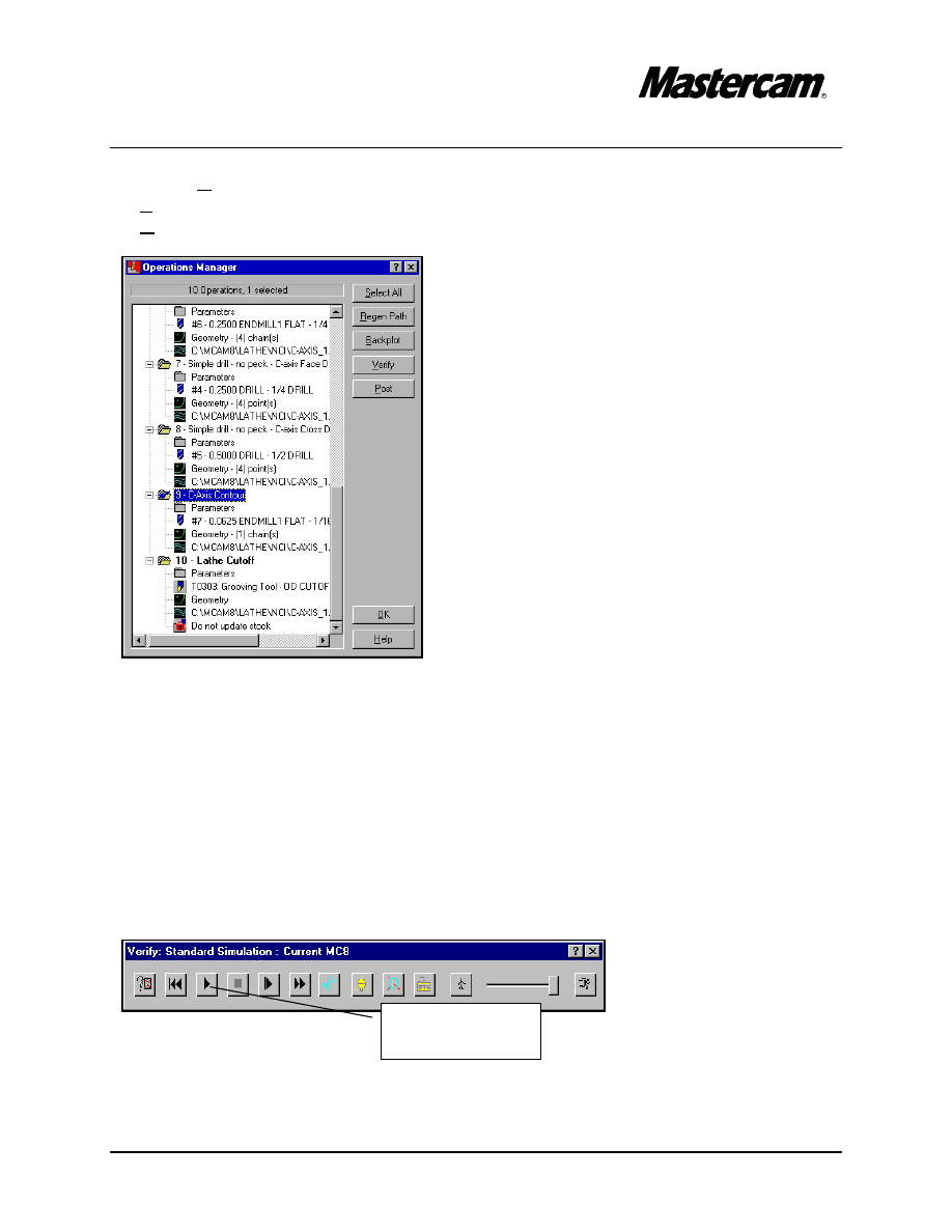
BACKPLOT THE TOOLPATH.
#"
Operations
#"
(From the Operations Manager dialog) Select All
#"
(From the Operations Manager dialog) Backplot
#"
Run
If you would like to watch the toolpath run slower, instead of Run, select Step. Hold
down the S key on your keyboard, or keep pressing the Step key and you will be able to
see the entire program at the speed that you wish, and be able to stop it at any time.
Press BACKUP to return to the Operations Manager dialog.
#"
Right click on an empty space in the white box
#"
Options
#"
Toolpath display
#"
Off
#"Select OK button to exit
Operations Manager
.
TUTORIAL 6
Page 6-34
STEP 16:
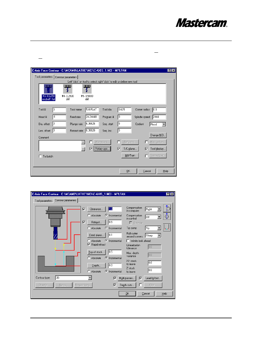
FACE CONTOURING.
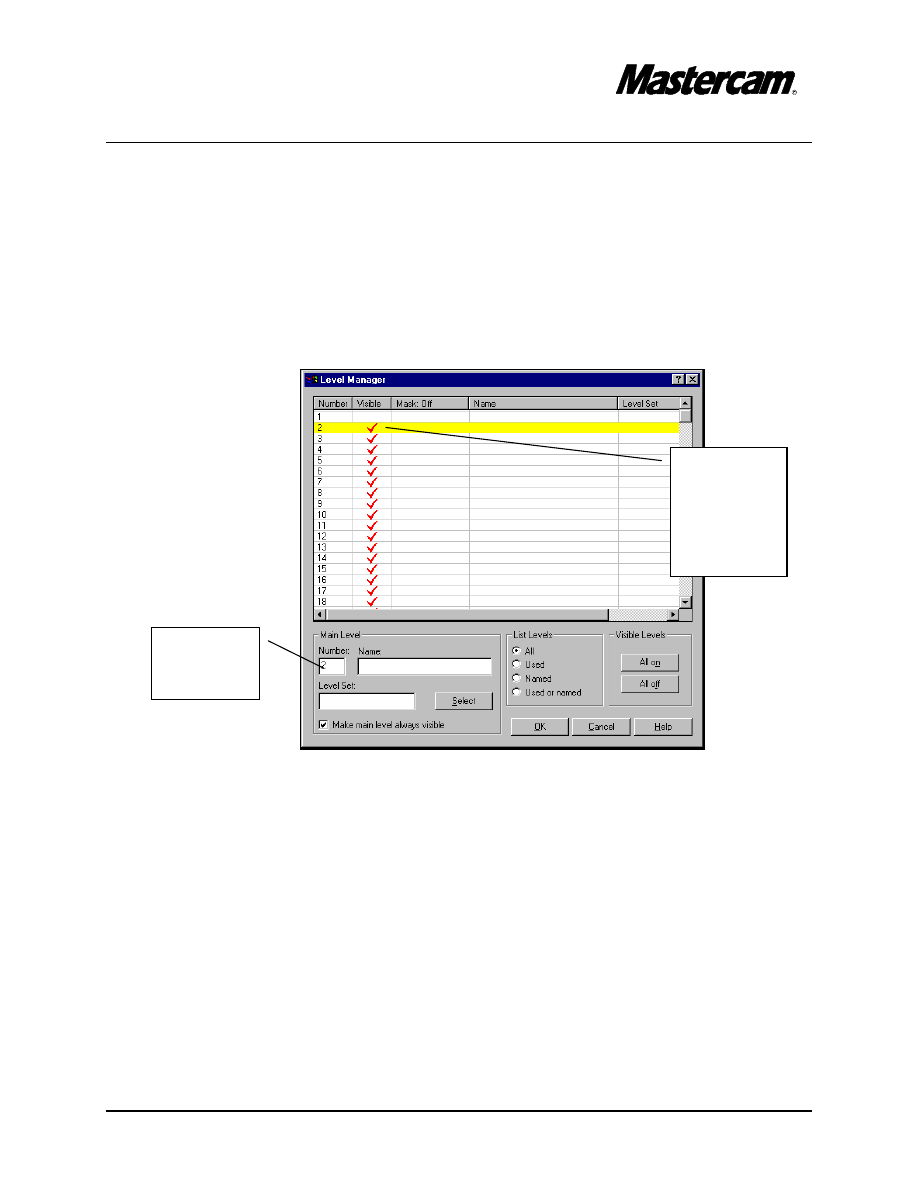
Change the Main Level to Level 1 and make invisible Level 2.
#"
Level
#"
To change the main level to 1 under Main Level Number type 1
#"
Make invisible Level 2 by disabling the check mark next to Level 2 as shown in the
following screen shot.
#"
Select OK button to exit.
$You shoul be able to see only the 3D part.
#"
Change the Gview to Isometric.
#"
Change Cplane to Side.
Change
the Main
Level to 1
Click here
to make
Level 2
invisible
TUTORIAL 6
Page 6-35
MAIN MENU
#"
Toolpaths
#"
Next Menu
#"
C-axis
#"
Face ctr
#"
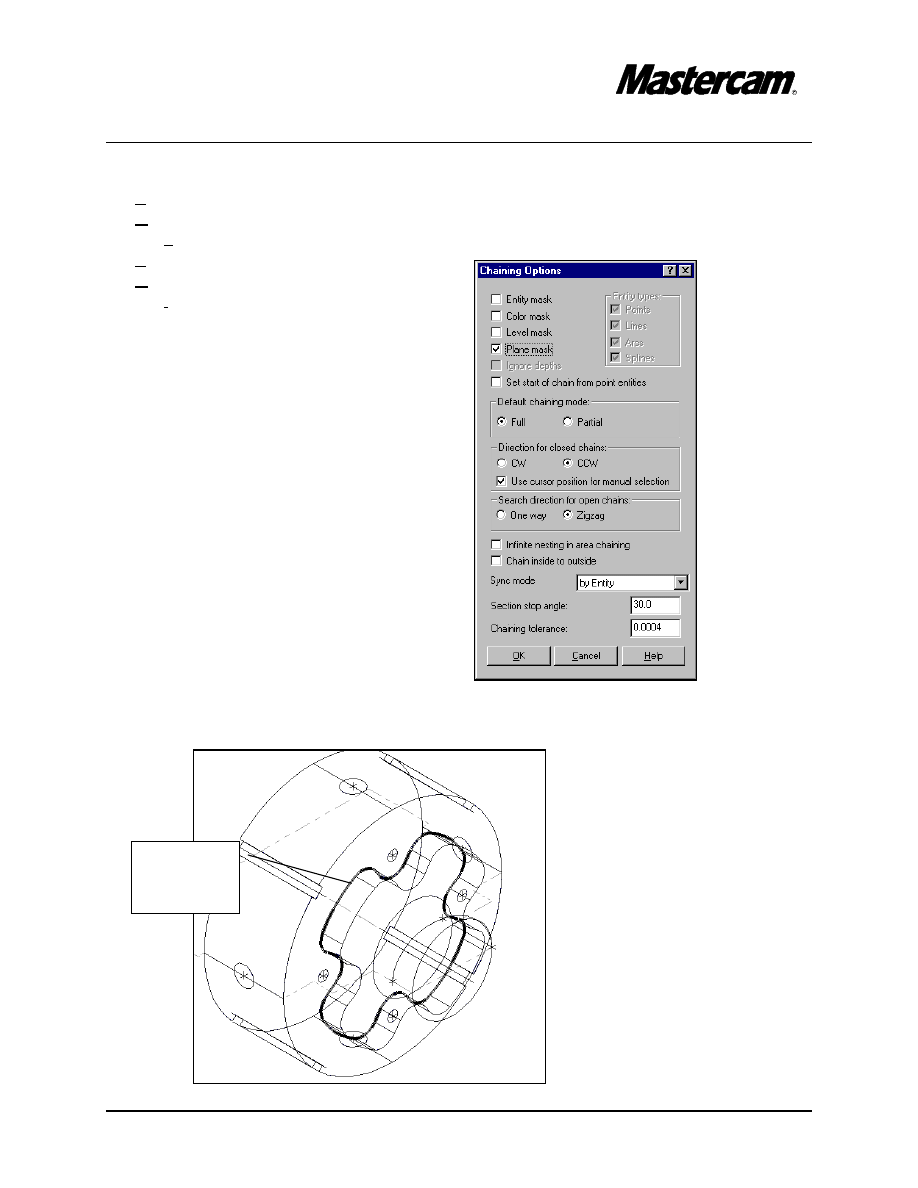
Chain
#"
Options
#"
Enable Plane mask as shown in the
following screen shot.
#"
Select OK button to exit Chaining
Options dialog box.
#"
Select the contour as shown in the following picture.
Select the
contour
here
TUTORIAL 6
Page 6-36
#"
The chaining direction has to be CCW if not select Reverse.
#"
Done
#"
Get from the library a 5/8 “ Flat End Mill.
#"
Select parameters and make the changes as shown in the following screen shots.
TUTORIAL 6
Page 6-37
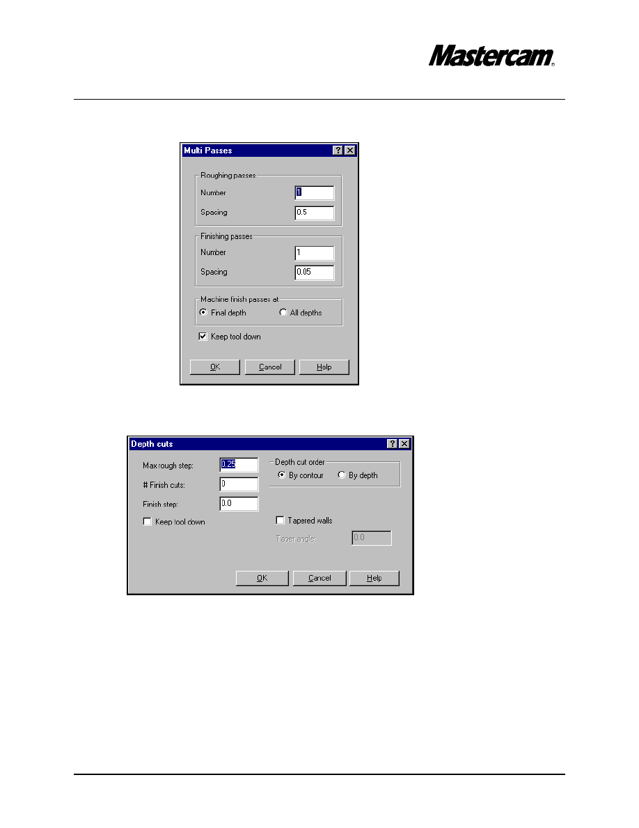
#"
Select Multi passes button and set the parameters to match the following screen
shot.
#"
Select OK button to exit Multi Passes dialog box.
#"
Select Depth cuts button and set the parameters to match the following screen shot.
#"
Select OK button to exit.
TUTORIAL 6
Page 6-38
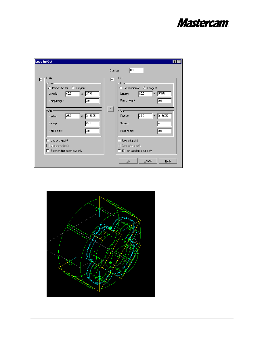
#"
Select Lead in/out button and set the parameters to match the following screen shot.
#"
Select OK button to exit.
#"
Select OK button to exit Face contour parameters.
TUTORIAL 6
Page 6-39
STEP 17:
CROSS CONTOURING.
#"
Rotate the part by simultaneously pressing the Alt key and the left cursor key (
%).
MAIN MENU
#"
Toolpaths
#"
Next Menu
#"
C-axis
#"
Cross ctr
#"
Single
#"
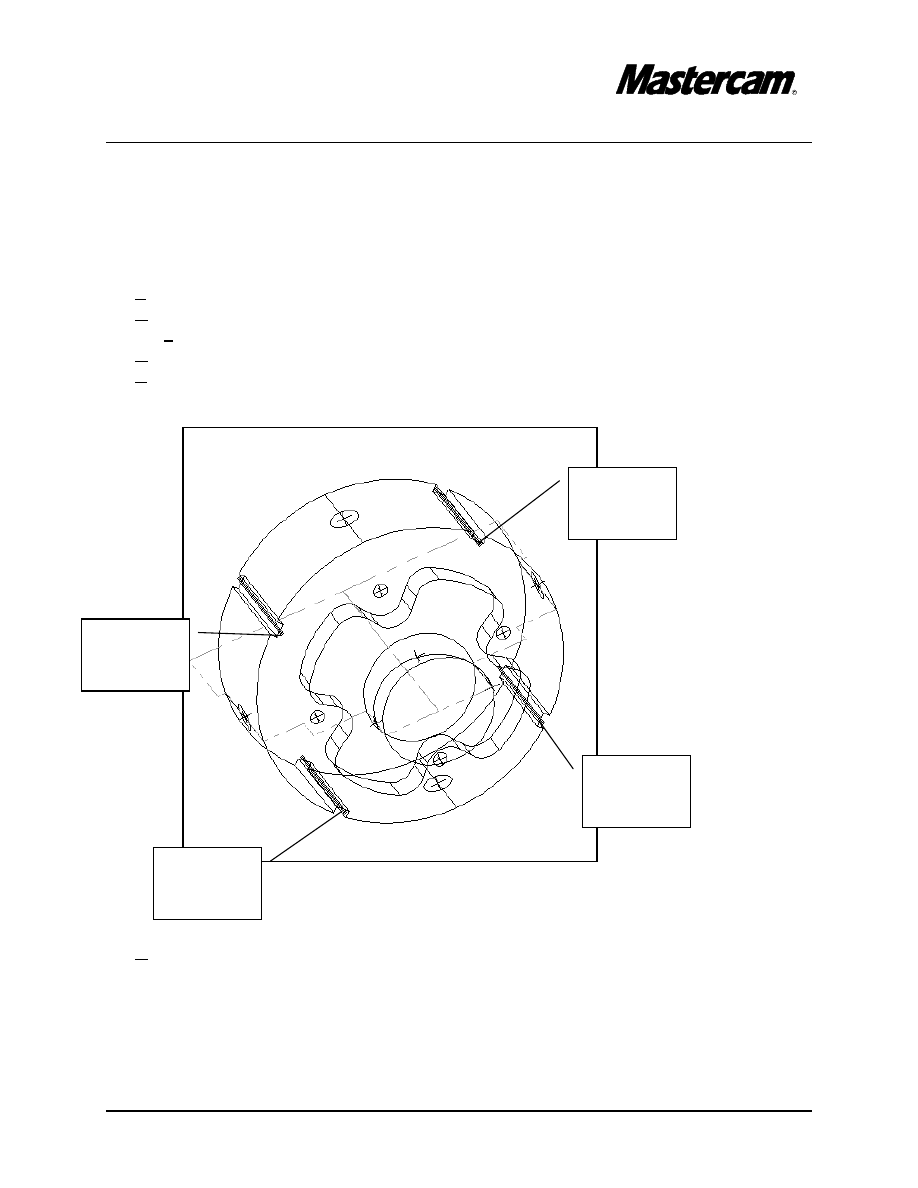
Select the contours as shown in the following picture.
#"
Done
Select the
first line
here
Select the
second
line
Select the
third line
here
Select the
last line
here
TUTORIAL 6
Page 6-40
#"
Get a ¼ “ Flat End Mill from the library.
#"
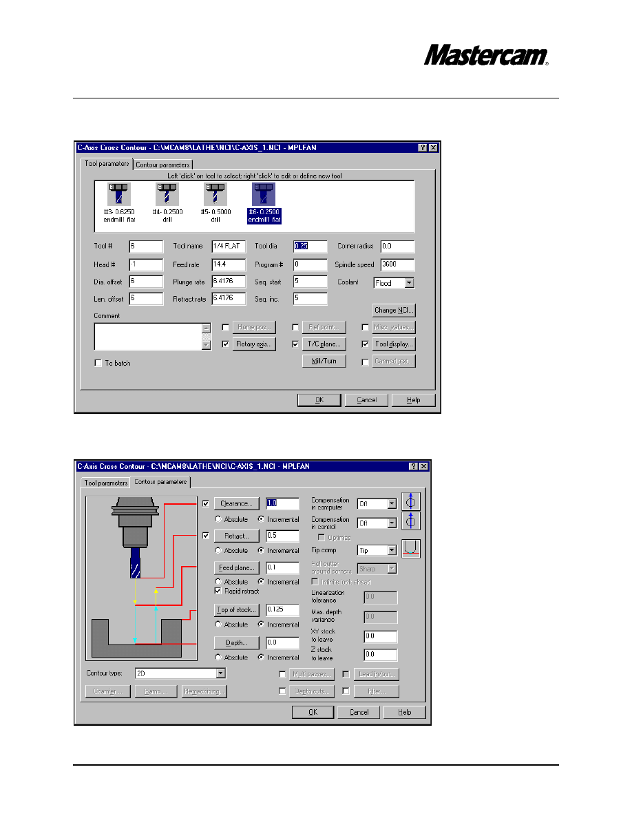
Select Contour parameters page and make the necessary changes as shown in the
following screen shot.
TUTORIAL 6
Page 6-41
#"
Select OK button to exit parameters.
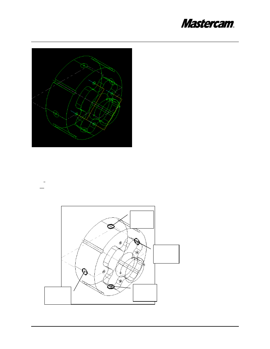
STEP 18:
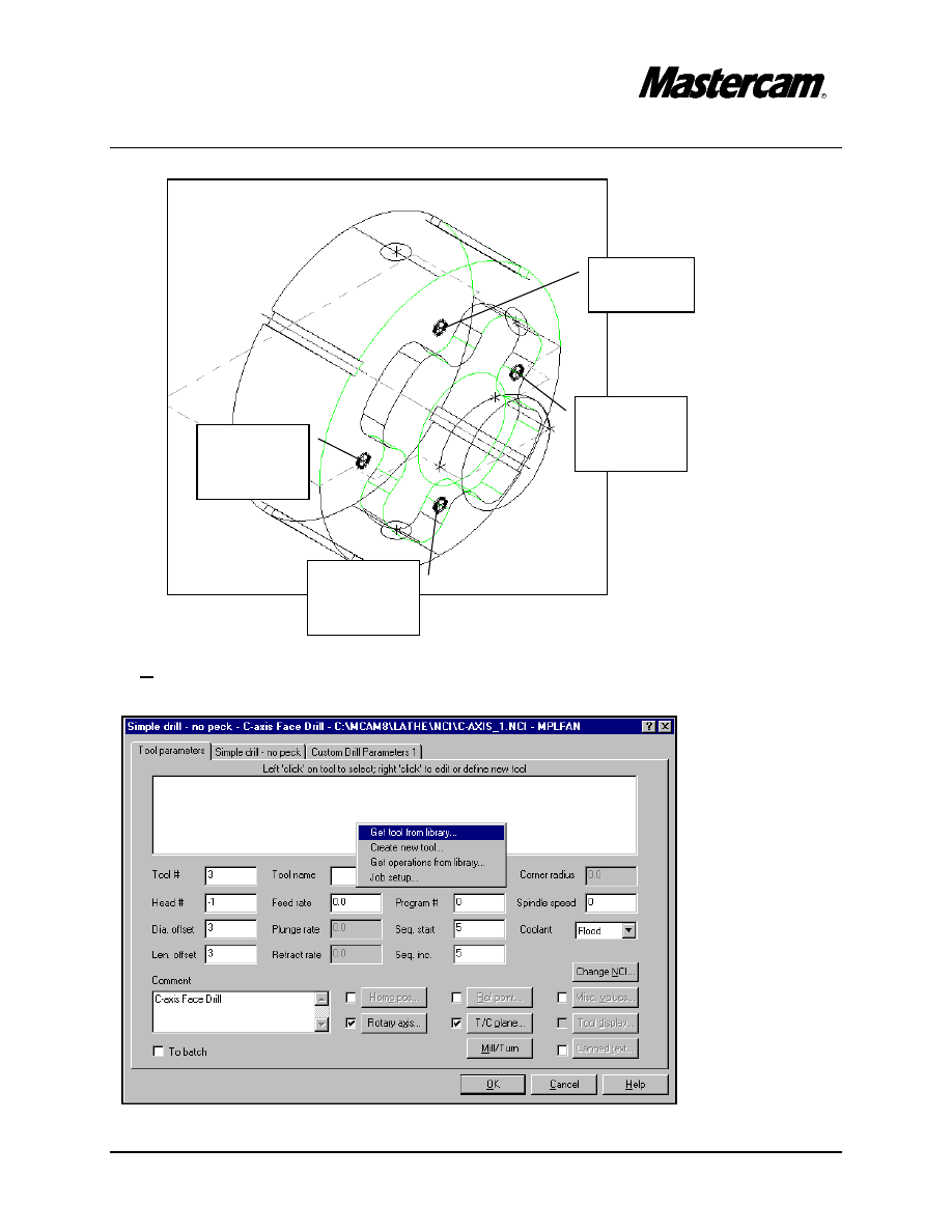
FACE DRILLING.
MAIN MENU
#"
Toolpaths
#"
Next menu
#"
C-axis
#"
Face drl
#"
Manual
#"
Select the points as shown in the following picture, starting with Point 1 to Point 4.
( this will be the order in wich they will be machined)
TUTORIAL 6
Page 6-42
#"
Press Esc to disable the checking.
#"
Done
#"
Righ-mouse click in the middle of the white window and select Get tool from library.
Select
Point 1
Select
Point 2
Select
Point 3
Select
Point 4
TUTORIAL 6
Page 6-43
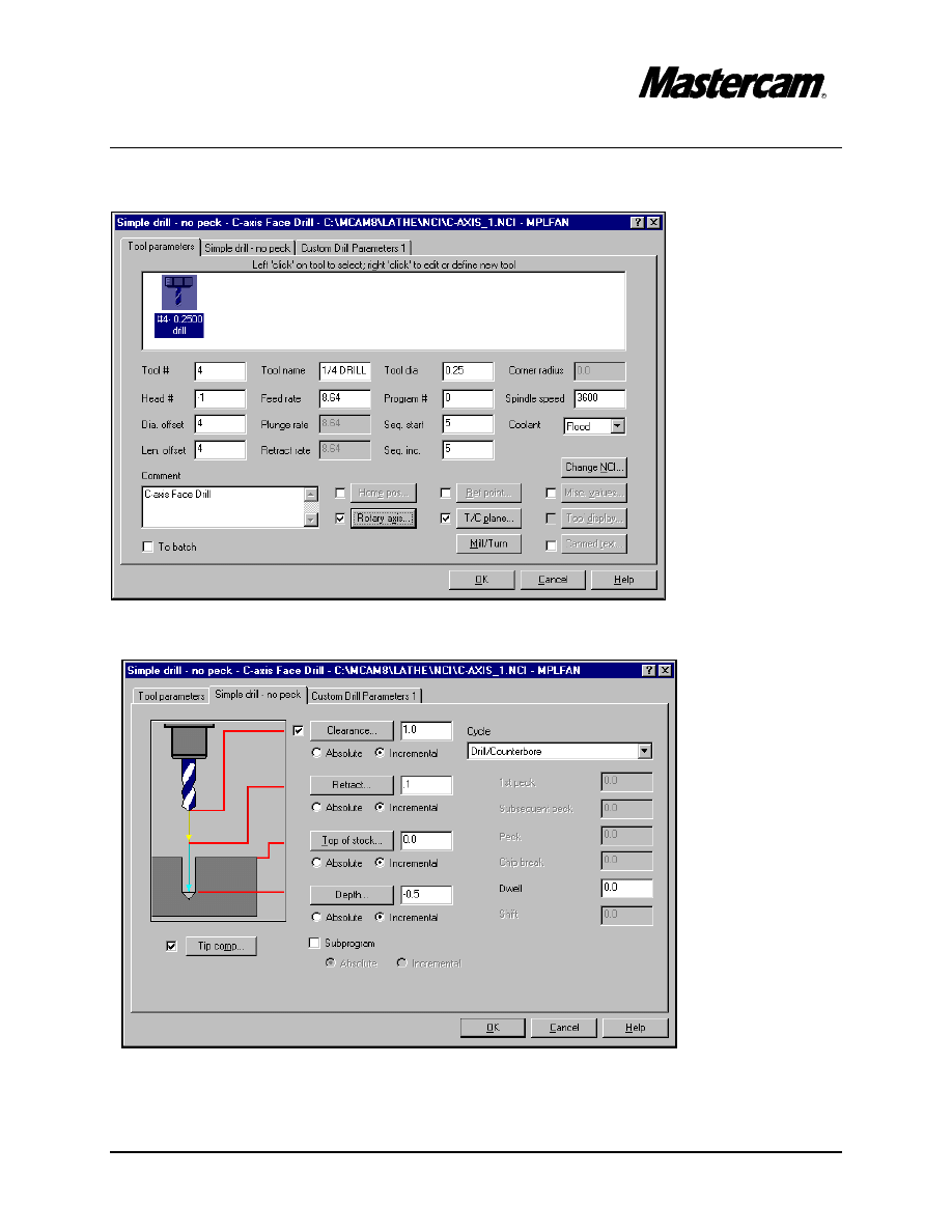
#"
Select the ¼ “diameter Drill
#"
Select Simple drill –no peck page and make the following changes.
$ Note that all parameters are incremental. This instructs the system to measure the
distances from the selected points’ z value.
TUTORIAL 6
Page 6-44
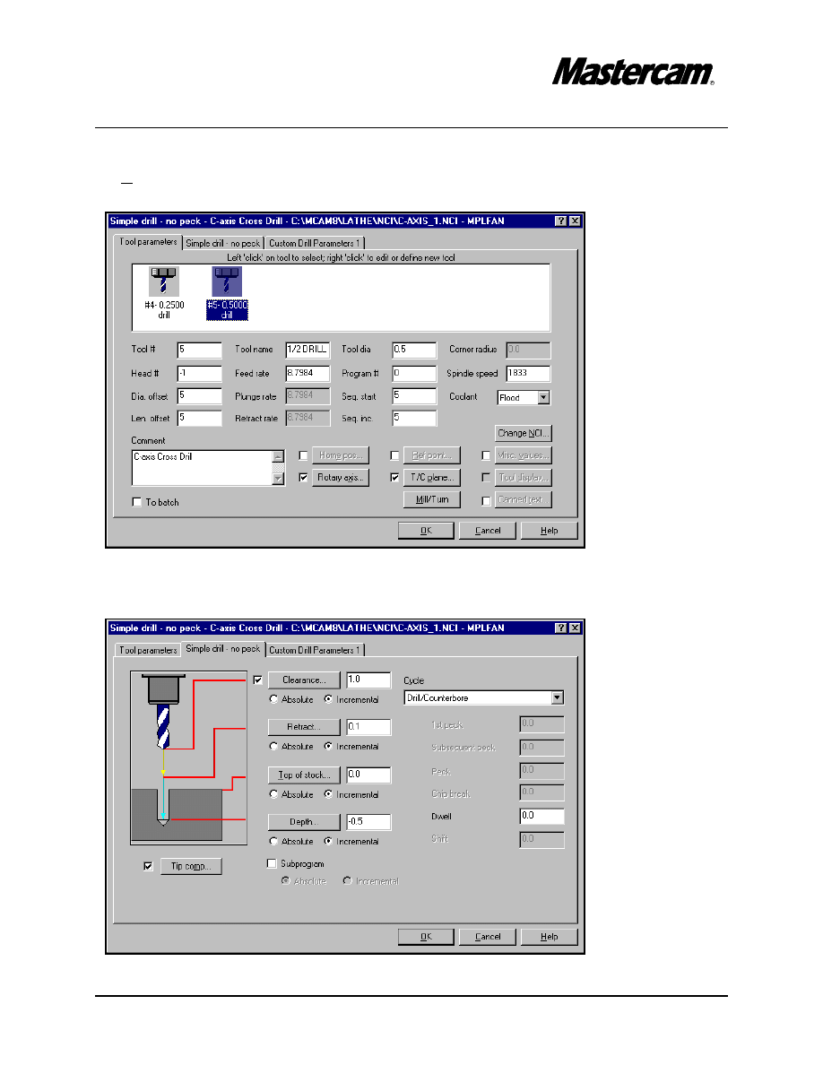
STEP 19:
CROSS DRILLING.
#"
Cross drl
#"
Manual
#"
Select the points as shown in the following picture, starting with Point 1 to Point 4.
( this will be the order in wich they will be machined)
Select
Point1
Select
Point 2
Select
Point 3
Select
Point 4
TUTORIAL 6
Page 6-45
#"
Press Esc to disable checking.
#"
Done
#"
Get ½ “ Drill from the library.
#"
Select Simple drill – no peck page and change the parameters as shown in the
following screen shot.
TUTORIAL 6
Page 6-46
#"
Select OK button to exit parameters.
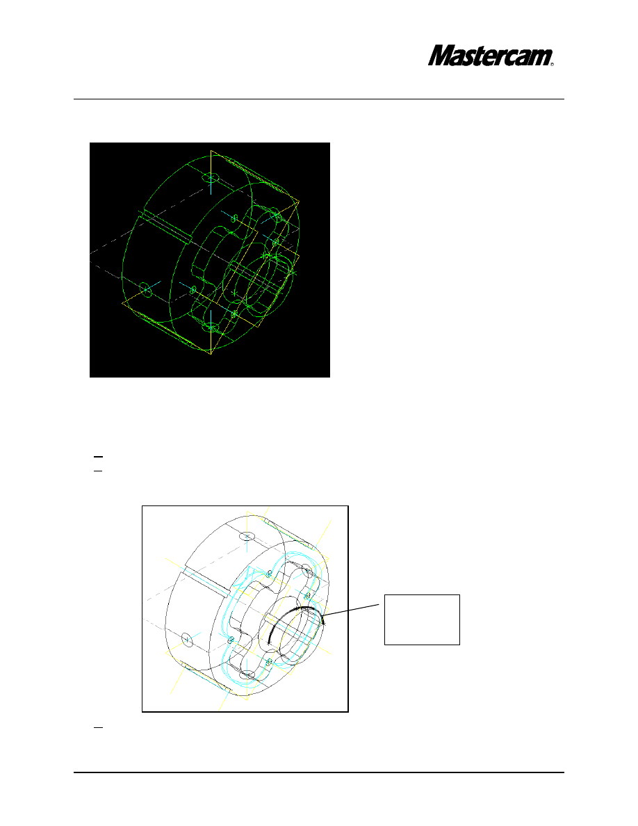
STEP 20:
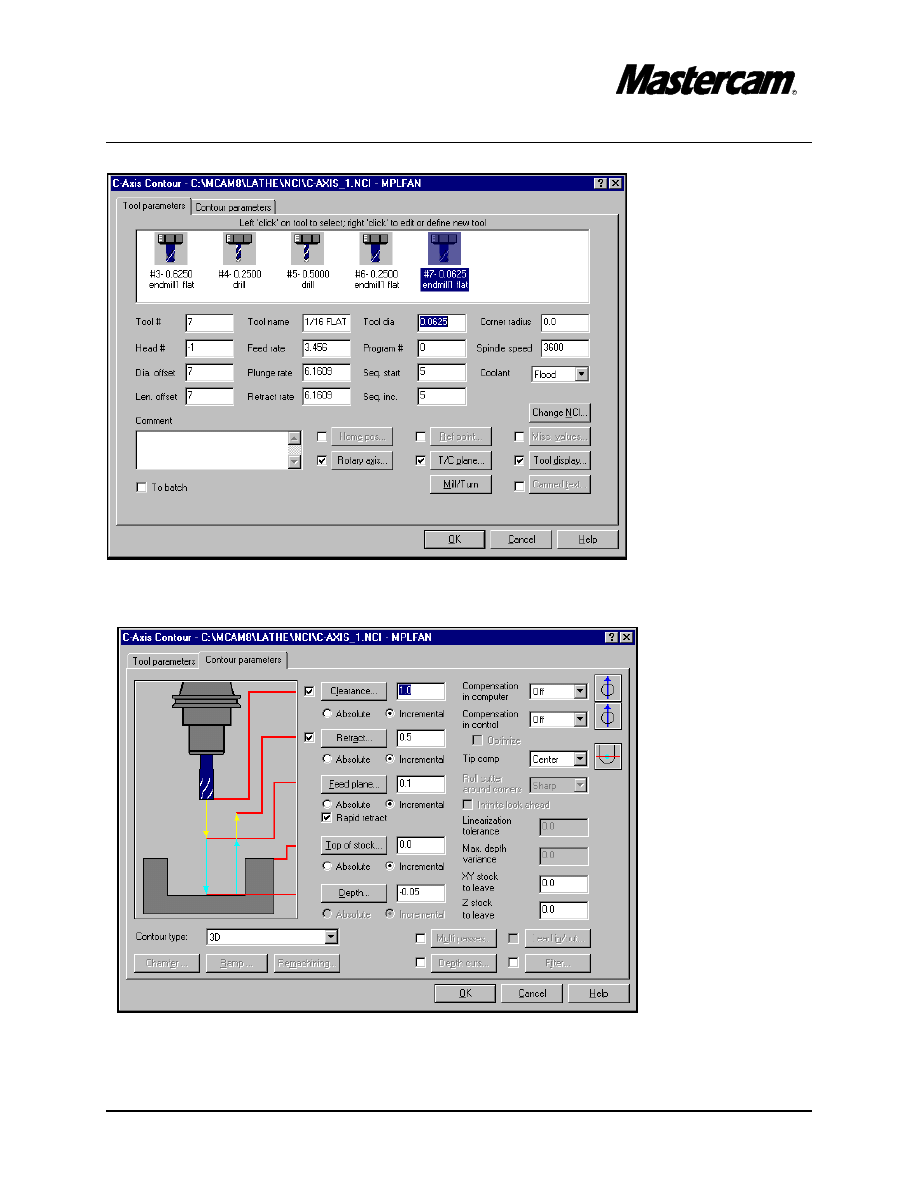
C-AXIS CONTOURING.
#"
C-axis ctr
#"
Single
#"
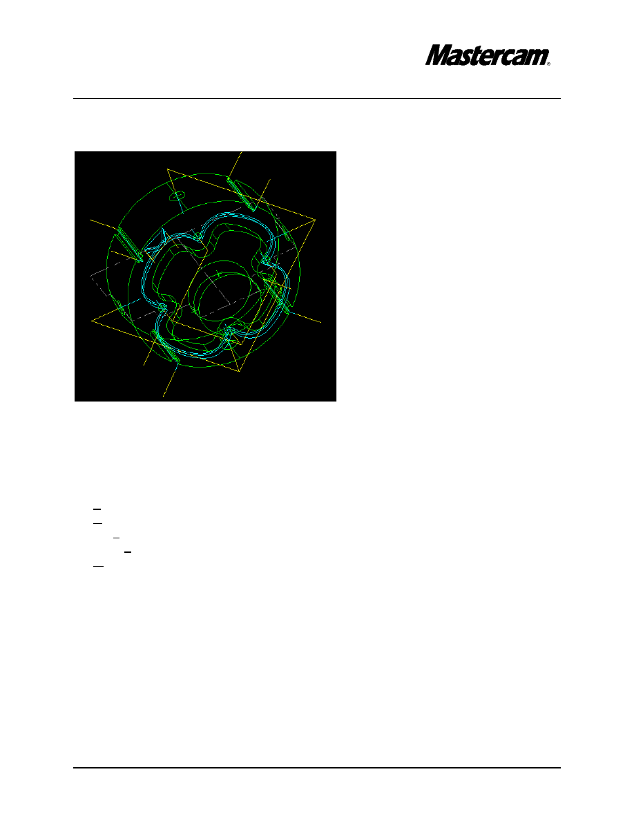
Select the contour as shown in the following picture.
#"
Done
#"
Get a 1/16 “ Flat End Mill from the library.
Select the
arc here.
TUTORIAL 6
Page 6-47
#"
Select Contour parameters page and change the parameters as shown in the
following screen shot.
#"
Select OK button to exit parameters screen.
TUTORIAL 6
Page 6-48
STEP 21:
CUTOFF THE PART.
#"
Backup
#"
Change Cplane to +DZ
#"
Make sure that construction depth Z=0
MAIN MENU
#"
Toolpaths
#"
Next Menu
#"
Cutoff
#"
[Select boundary point]: 5.5,-3.5
TUTORIAL 6
Page 6-49
#"
Select the same cutoff tool that we used for grooving.
#"
Select Cutoff parameters page and set parameters to match the following screen
shot parameters.
TUTORIAL 6
Page 6-50
#"
Select OK button to exit.
#"
Backup
#"
Operations
$Note that Lathe Cutoff operation has a locker icon and a message Do not update
stock. Click on the locker icon to disable it.
#"
Select Regen path button to update the stock.
STEP 22:
VERIFY- TOOLPATH VERIFICATION
#"
Select Verify
#"
Select Machine button.
Select Machine
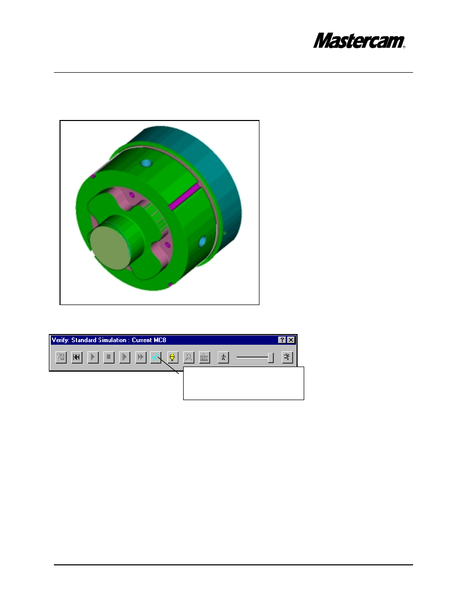
TUTORIAL 6
Page 6-51
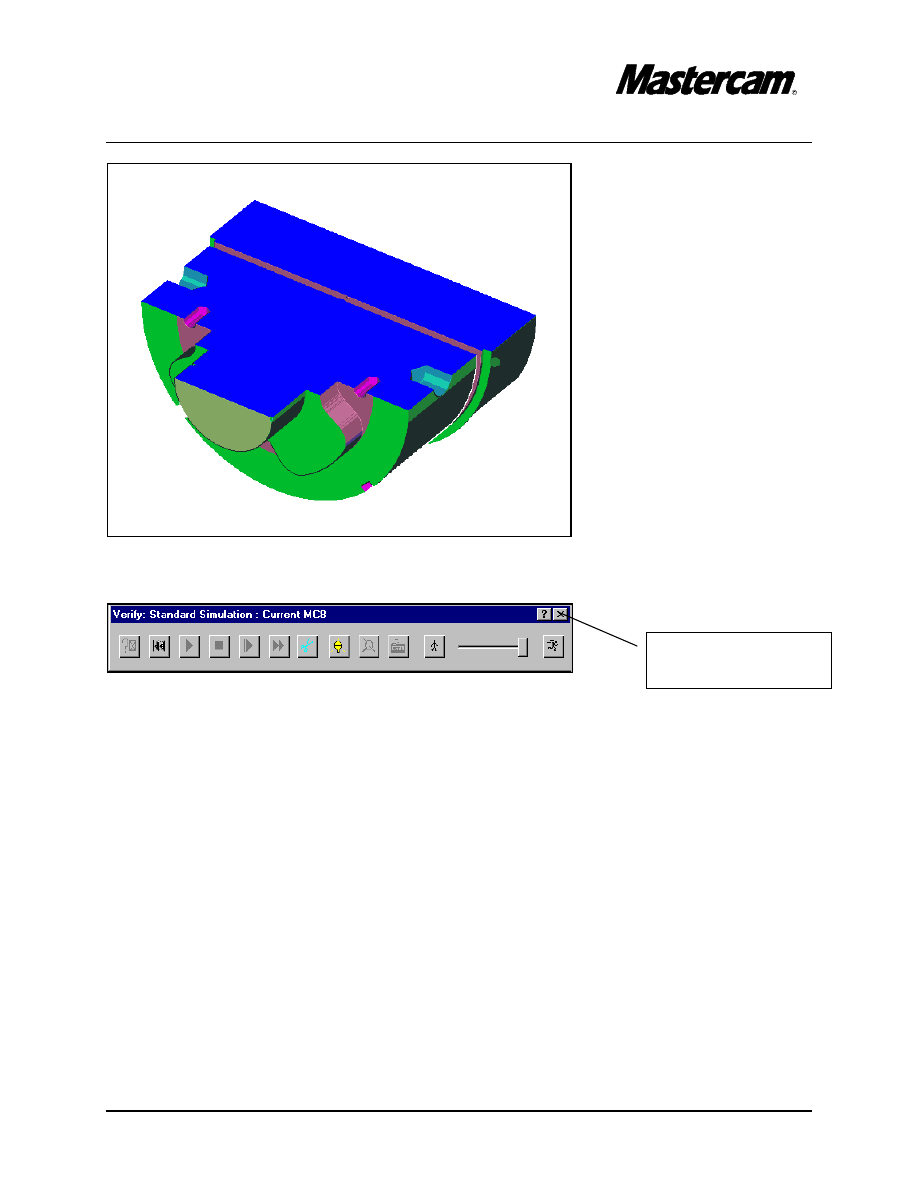
The computer will now simulate the process of the part being machined.
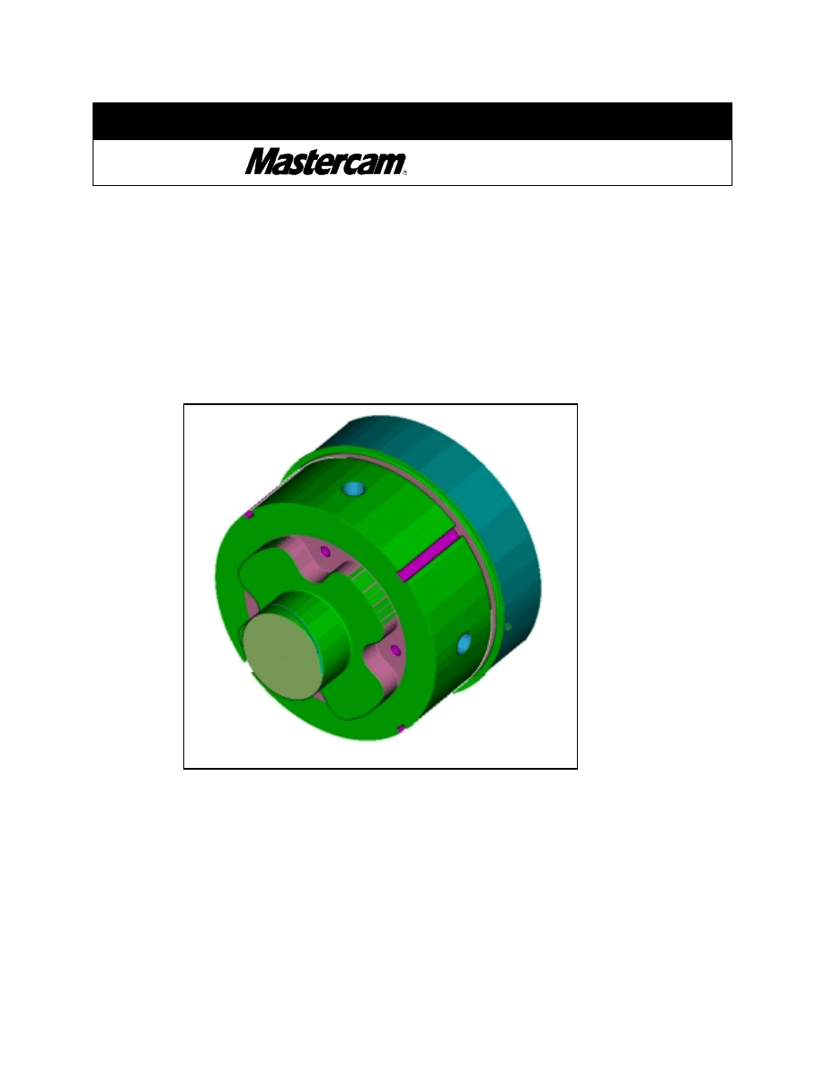
The finished part should appear as shown in the following picture.
#"
Select stock section button to make a section through the part.
Select this icon to make a
section through the part
TUTORIAL 6
Page 6-52
#"Exit Verify.
#"Select OK to close Operation Manager.
Select this button to
exit Verify

TUTORIAL 6
Page 6-53
STEP 23:
POST THE FILE TO OBTAIN THE G-CODE FILE.
$
$
$
$ This tutorial covers Mastercam’s C-axis toolpath functionality. To apply these
toolpaths to a C-axis lathe, a customized post processor for your machine may be
required.
There are default C-Axis post processors included with Mastercam, such as
MPLFAN, MPLOKUHW, MPLTL3YC, MPLTL56T, AND MPLTPLSC. Due to the
variation in C-axis machine configurations contact your Mastercam reseller to
request post processor services such as C-axis post development.
Your post processor may require certain additional programming information not
covered in this tutorial. The nature of the additional information required depends
largely on your machine’s configuration. Contact the developer of your post
processor for details.
#"
To post the file please follow Step 9 of Tutorial #1 pag. 1-17 to 1-19.
STEP 24:
SAVE THE UPDATED MC8 FILE.
MAIN MENU
#"
File
#"
Save
#"
Resave this drawing with the same name.
#"
[ Delete old … ] Yes
TUTORIAL 6
Page 6-54
Review Exercise
Document Outline
Wyszukiwarka
Podobne podstrony:
Mastercam Tutorial 3 PL
mazak tutorial mastercam
Mastercam Post Processor Tutorial 1(1)
Mastercam To Mazatrol Post Processor Tutorial r2
Mastercam Post Processor Tutorial 1
free sap tutorial on create material master
TOCZEŃ
Toczeń
dane mastertig2300mls
01 Certyfikat 650 1 2015 Mine Master RM 1 8 AKW M
bugzilla tutorial[1]
freeRadius AD tutorial
Alignmaster tutorial by PAV1007 Nieznany
free sap tutorial on goods reciept
ms excel tutorial 2013
MasterPlanRekrutacjaGrupowa2010
Joomla Template Tutorial
więcej podobnych podstron