
LEP
4.5.06
-00
Diffraction and polarization of microwaves
PHYWE series of publications • Laboratory Experiments • Physics • © PHYWE SYSTEME GMBH & Co. KG • D-37070 Göttingen
24506-00
1
Related topics
Diffraction, focal point, linearity, circularly and elliptically polar-
ized waves, transverse waves, polarizer, analyzer, constructive
and destructive interference.
Principle
The equivalence between visible light and microwaves as spe-
cial cases of the total spectrum of electromagnetic waves can
be demonstrated using diffraction and polarization of micro-
waves as an example. The focusing of microwaves through a
plane convex convergent lens is observed and the focal dis-
tance of the lens is determined. After that, polarizability of
microwaves is demonstrated by means of a metallic grating.
Equipment
Microwave transmitter w. klystron
11740.01
1
Microwave receiving dipole
11740.03
1
Microwave power supply, 220 VAC
11740.93
1
Universal measuring amplifier
13626.93
1
Polarisation grid
06866.00
1
Convergent lens, synthetic resin
06872.00
1
Protractor scale with pointer
08218.00
1
Voltmeter, 0.3-300 VDC, 10-300 VAC
07035.00
1
Screened cable, BNC, l = 1500 mm
07542.12
1
Connecting cord, l = 500 mm, red
07361.01
1
Connecting cord, l = 500 mm, blue
07361.04
1
Connecting cord, l = 2000 mm, red
07365.01
1
Connecting cord, l = 2000 mm, blue
07365.04
1
Adapter, BNC-socket/4 mm plug pair
07542.27
1
Tripod base -PASS-
02002.55
1
Barrel base -PASS-
02006.55
1
H-base -PASS-
02009.55
1
Bench clamp -PASS-
02010.00
2
Support rod -PASS-, square, l = 250 mm
02025.55
1
Support rod -PASS-, square, l = 630 mm
02027.55
4
Right angle clamp -PASS-
02040.55
4
Stand tube
02060.00
1
Meter scale, demo, l = 1000 mm
03001.00
1
Tasks
1. Measuring the irradiance of the microwave field behind a
converging lens
– along the optical axis
– transversally to the optical axis.
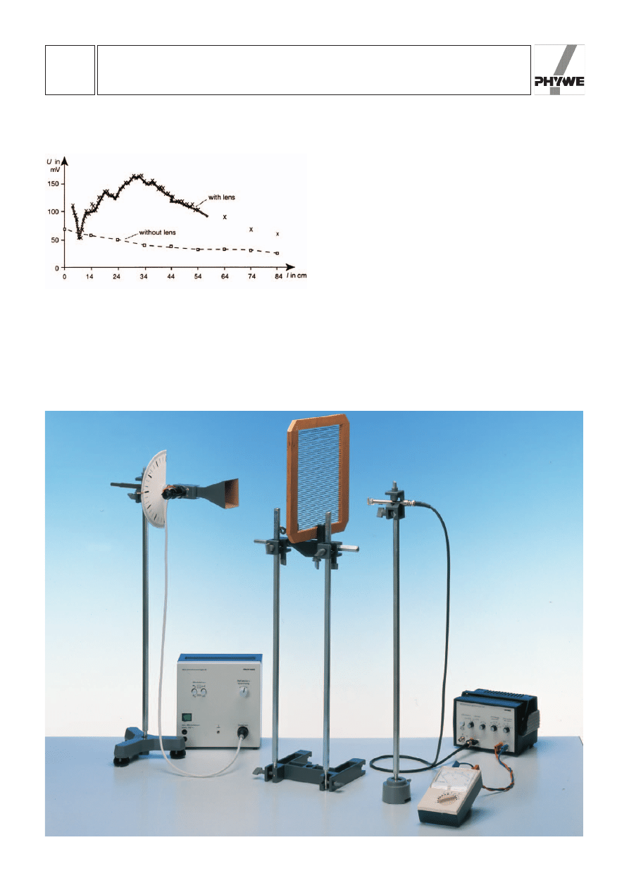
Fig.1a: Experimental set-up to determine the focal point of a synthetic resin plastic lens.
LEP
4.5.06
-00
Diffraction and polarization of microwaves
24506-00
PHYWE series of publications • Laboratory Experiments • Physics • © PHYWE SYSTEME GMBH & Co. KG • D-37070 Göttingen
2
Determination of the focal length of a synthetic resin conver-
ging lens and comparison of the results with the distribution of
irradiance when no lens is used.
2. Measurement of the irradiance transmitted through a metal
grating as a function of the angle between the direction of
polarization and the grating bars.
Set-up and procedure
1. The set-up required to determine the focal point of the syn-
thetic resin lens is shown in Fig. 1 a. The transmitting and
receiving equipment is situated approx. 65 cm above the sur-
face of the table, in order to minimize disturbing interference
due to reflection from the surface of the table. The fact that the
measuring instruments also may reflect microwaves must be
taken into account when positioning the instruments. It is rec-
ommended to place the microwave emitter (without amplitude
modulation) about 100 cm from the receiving dipole and
approx. 80 cm from the front end of the scale, which is
attached with a bench clamp. The voltage of the receiving
dipole is connected to the “low drift” input of the measure-
ment amplifier. The reflecting voltage of the clystron (
O = 9.45
GHz, corresponding to a wavelength of
M = 3.18 cm) and the
orientation of the transmitting antenna are adjusted to the
maximum DC voltage signal of the receiving dipole. The
receiving dipole must be oriented parallel to the narrow side of
the horn antenna (polarization direction) to assure the maxi-
mum reception signal. For control purposes it should be
checked that the receiving dipole remains on the optical axis
when the barrel base is shifted on the measuring scale, e. g.
by measuring the distance to the edge of the table. The cylin-
Fig. 2: Intensity of radiation as a function of the distance
between the lens and the receiving dipole.
Fig.1b: Experimental set-up

LEP
4.5.06
-00
Diffraction and polarization of microwaves
PHYWE series of publications • Laboratory Experiments • Physics • © PHYWE SYSTEME GMBH & Co. KG • D-37070 Göttingen
24506-00
3
drical lens is centered by shifting it immediately before the
measuring scale and perpendicularly to the optical axis, until
the maximum DC voltage signal of the receiving dipole (at a
distance of approx. 25 cm.) is reached. The obtained distribu-
tion of irradiance (proportional to the rectifying diode voltage
and to the square of the amplitude of field intensity
E
2
) along
the optical axis is plotted as a function of the distance
between the receiving dipole and the cylindrical lens. This
experiment is repeated without converging lens at a distance
of 10 cm for comparison.
The focusing effect of the converging lens is demonstrated by
recording the irradiance profile at a distance of 20 cm, 30 cm
and 40 cm of the lens, perpendicularly to the optical axis. The
point of reference for the distance measurements is the sur-
face of the convex side of the lens, near which the main
planes of the lens (thick lens) are situated. For this purpose,
the measuring scale is fixed to the table perpendicularly to the
optical axis at the corresponding distances.
2. To check the transmittance of a polarization screen, the
converging lens is substituted by a metal grating with its bars
oriented perpendicularly to the receiving diode Fig 1b. A sem-
icircular scale is attached to the microwave transmitter (situat-
ed approx. 20 cm from the metal grating), which is fixed to a
stand tube so that it can pivot. The corresponding pointer is
attached to the stand tube, so that it is possible to read the
angle of rotation of the microwave transmitter. As the direction
of oscillation of the electric field vector is parallel to the narrow
side of the funnel, the angle a of inclination of polarization
related to the grating bars is given. The angle a of inclination
is varied from 0° to 90° in steps of 50 and the corresponding
DC voltage signal at the receiving dipole is recorded. It should
be made sure that the voltage at the receiving dipole is maxi-
mum exactly at the same moment the receiving diode is
oriented perpendicularly to the grating bars.
Theory and evaluation
1. Diffraction of electromagnetic waves
Similarly to visible light, the speed of propagation of micro-
waves depends on the material they travel through: combina-
tion of Maxwell’s equation in dielectric media yields the follow-
ing result for the phase velocity v
PH
of an electromagnetic
wave in general (c being the speed of light, e the dielectric
constant and m permeability):
(1)
or, with permeability m
1 (this is the case for non ferromag-
netic materials), phase velocity v
PH
is inversely proportional to
the root of the dielectric constant.
(Maxwell’s Relation)
(2)
The dielectric constant
F depends both on the type of materi-
al as well as on the frequency of the propagating electromag-
netic wave.
In case of a microwave (f = 9.45 GHz) the following applies for
the absolute diffraction indexes:
with n
air
< n
synthetic resin
(3)
At the boundary surface between air and synthetic resin,
reflection and diffraction occur just as in geometrical optics:
the plane convex cylindrical lens thus acts as a converging
lens for microwaves. Therefore, a significantly larger illumi-
nance is observed along the optical axis after the lens (cf.
Fig. 2) as would be the case for the same set-up without lens.
Due to conservation of energy, illuminance outside the optical
axis must be smaller (cf. Fig. 3): the microwaves are bunched
together. If the microwaves impinging on the cylindrical lens
are approximated by plane waves (this may be done because
the distance between transmitter and lens is large as com-
pared to the dimensions of the lens) and neglecting diffraction
through the lens, the peak in Fig. 2 represents the focal point
of the lens (more correctly the focal line). The focal distance of
the lens (related to the main plane) is thus:
f = 31 cm ± 3 cm.
n:
c
v
PH
2e
v
PH
c
2e
v
PH
c
2em
Fig. 3: Profile of the intensity of radiation.
Fig. 4: Transmission through a metal grating.

LEP
4.5.06
-00
Diffraction and polarization of microwaves
24506-00
PHYWE series of publications • Laboratory Experiments • Physics • © PHYWE SYSTEME GMBH & Co. KG • D-37070 Göttingen
4
However, diffraction at the lens (wavelength l = 3.18 cm, only
a little smaller than the dimensions of the converging lens) as
well as interference with reflected waves cause significant
deviations from the laws of geometrical optics. This can be
recognized from the secondary diffraction peaks in figures 2
and 3.
2. Polarization of electromagnetic waves
Microwaves, as all electromagnetic waves, oscillate transver-
sally and thus have two degrees of freedom related to the
direction of polarization. Every linear polarization of a trans-
verse plane wave propagating along the z-axis can thus be
divided into two perpendicular components:
(4)
General solutions of Maxwell’s equations with a phase shift
between the two components are called elliptically polarized
waves:
(5)
The time relationship of the electric field vector
for a fixed
localization
becomes clear for the special case
[E
x
[ =
[E
y
[ and
X
0
= (2 n + 1)
Q; n = 0, 1, …:
The
vector of the microwave field (and thus the magnetic
field intensity vector
perpendicular to this) rotates with the
period
with constant amplitude, perpendicularly to the direction of
propagation.
The microwaves used in this case are already linearly polar-
ized when they leave the transmitting antenna. The metal grat-
ing acts as an analyzer which allows to determine the direc-
tion of polarization of the microwaves. If a microwave, whose
vector is polarized parallel to the grating bar, impinges on
the grating, the free charge carriers in the metal are excited
into oscillation by the high frequency field, which in turn pro-
duces a microwave field with opposite phase: a stationary
wave is built up before the screen, which can be detected by
the receiving dipole set up parallel to the grating. The two
waves interfere to zero behind the grating, inasmuch as the
distance between the grating bars is significantly smaller than
the wavelength. This means that the transmitted irradiance
vanishes after the grating.
If, on the other hand, the angle between the direction of pola-
rization of the incident microwave and the direction of the
grating bars is a = 90°, the free charge carriers cannot oscil-
late freely along the field lines, and in this case the incident
microwave passes through the polarizing grating without
being weakened.
In the general case (cf. Fig. 4) of a direction of polarization
which forms an angle a with the grating, the incident wave is
decomposed into a partial wave with a polarization direction
parallel to and one with a polarization direction perpendicular
to the grating bars, of which only the latter is transmitted.
Thus, of the transmitted amplitude E
0
, only the following por-
tion reaches the microwave detector:
E
trans
= E
0
sina
(6)
The received irradiance (proportional to E) of the transmitted
microwave correspondingly is:
I
trans
= I
0
sin
2
a
(7)
where I
0
is the (maximum) intensity for a = 90 ° (cf. Fig. 5).
In the case of non polarized, “natural” microwaves, the metal
grating can also be used as a polarizer, as only microwaves
polarized perpendicularly to the grating bars are found after
the grating.
Caution
Although the clystron only has low power, one must avoid
looking directly into the microwave.
E
S
T
2p
v
H
S
E
S
E
S 1 rS
0
,t
2 E
x
°
cos
1vt2
± sin
1vt2
0
¢
r
S
0
0
E
S
E
S 1 rS,t2 E
x
cos
1 k
S
r
S
vt
2 e
S
x
E
y
cos
1 k
S
r
S
vtw
0
2 e
S
y
E
S 1 rS,t2 E
x
cos
1 k
S
r
S
vt
2 e
S
x
E
y
cos
1 k
S
r
S
vt
2 e
S
y
Fig. 5: Transmitted radiation intensity as a function of sin
2
a of
the angle of incidence.
Wyszukiwarka
Podobne podstrony:
PHYWE P2450500 Diffraction of m Nieznany
American Political System Lack of Cooperation and Polariza
Characterization of microwave vacuum drying and hot air drying of mint leaves (Mentha cordifolia Opi
Drying kinetics and quality of vacuum microwave dehydrated garlic cloves and slices
PHYWE P2450400 Interference of microwaves
Drying kinetics and rehydration characteristics of microwave vacuum and convective hot air dried mus
Drying kinetics and quality of beetroots dehydrated by combination of convective and vacuum microwav
05 DFC 4 1 Sequence and Interation of Key QMS Processes Rev 3 1 03
IR and philosophy of history
Microwaves in organic synthesis Thermal and non thermal microwave
Guide to the properties and uses of detergents in biology and biochemistry
African Filmmaking North and South of the Sahara
In vivo MR spectroscopy in diagnosis and research of
Microstructures and stability of retained austenite in TRIP steels
Poland and?lsifications of Polish History
Sterne The Life and Opinions of Tristram Shandy, Gentleman
SHSBC418 The Progress and Future of Scientology
The?uses and?fects of the Chernobyl Nuclear Reactor Melt
więcej podobnych podstron