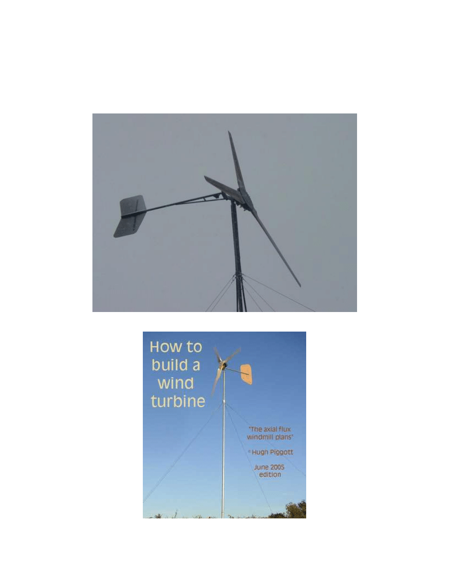
Basic Principles Of The Homemade Axial Flux Alternator
Steven Fahey
Version 1 December 18, 2006
Page 1 of 15
If you are new to the topic of building Permanent Magnet Alternators, then this is for you! My
purpose is to help people learn about the DIY wind turbines that are gaining in popularity.
Basic concepts are introduced here, but it’s still up to you to read on; this hobby is very
multidisciplinary! For every topic, you can find a wealth of additional information – I hope I can
help start you off in the right direction. Those with corrections or suggestions are welcome to
contribute.
A Successful 17’ Wind Turbine Design by Dan Bartmann (www.otherpower.com)
Hugh Piggott’s Popular Design Manual (www.scoraigwind.com)
Basic Principles Of The Homemade Axial Flux Alternator
Steven Fahey
Version 1 December 18, 2006
Page 2 of 15
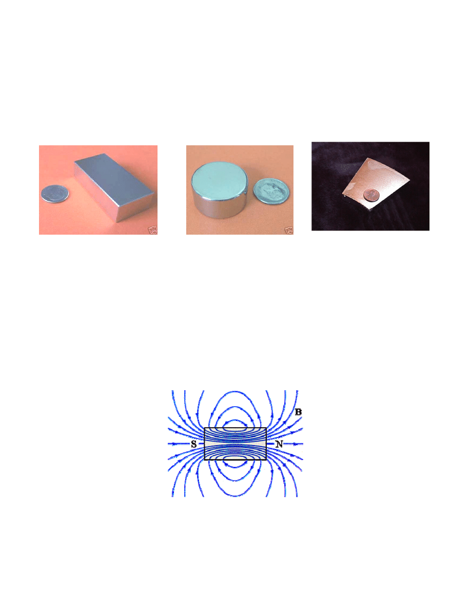
Magnets
The Neodymium magnet has been a key technological development that allows practical and
efficient alternators to be built. The high strength of Neodymium is part of what makes
computer hard drives so compact. Now the material is avaialble commercially for all sorts of
purposes. Many sizes now available are perfect for use in the DIY alternators. Below are
pictures of some common sizes that are used:
2” x 1” x 0.5”
1” Diameter x 0.5”
Circular Arc
“Magnetic field” is the technical term for the lines of force that are often drawn to symbolize the
magnetic field around the magnet. The magnetic field intensity is measured in either Teslas
(after the inventor Nikola Tesla), or Gauss (after the mathematician). The symbol “B” is used
for the field intensity (like “F” for force, “W” for weight). The intensity, B, gets stronger as you
get closer to the magnet, since the lines get closer together.
There is always a North Pole and a South Pole. The magnets we prefer to use have poles on
the faces with the most surface area. The example magnets shown above are more flat in one
direction: the poles are on the broadest faces. Some types of magnets are longer on the
polarized axis, but an axial flux alternator is efficient and lighter when the magnets are just big
enough for the job, and no bigger.
Magnetic Field Lines Around a Magnet
When magnets are made, the magnetic poles are “frozen in” with an external electromagnet as
the metal cools. If a magnet gets too hot, its strength will weaken.
Basic Principles Of The Homemade Axial Flux Alternator
Steven Fahey
Version 1 December 18, 2006
Page 3 of 15
Magnetic Fields
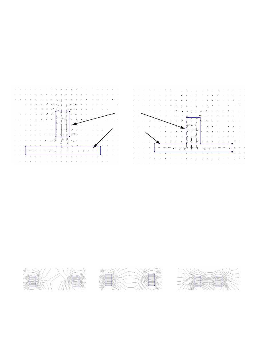
A few illustrations will improve the understanding of how magnetic fields are manipulated.
When magnets are attracted to metallic objects, the attraction can be witnessed by a distortion
of the field lines that we saw above. The lines are drawn to that object, in much the same way
that the object itself is drawn to the magnet. As the magnet gets closer to the plate, field lines
pass through the plate and get stronger. The increasing size of the arrows in the diagrams
below illustrates this.
MAGNET
IRON PLATE
Flux Lines Through an
Flux Lines Through an Object
Object Attracted to a Magnet
in Contact With a Magnet
When the plate is in contact with the magnet, the field lines can become very concentrated in
the plate. They concentrate themselves in the plate, and if the plate is thick enough, very few
lines emerge out the other side. Through the neodymium magnet itself, the magnetic strength
doesn’t change much.
In a sense, holding a magnet beside the plate of iron is like holding a ball above the ground.
The ball falls due to gravity, and it comes to rest at a lower potential energy. Same with the
piece of iron; once it is in contact with the magnet, the potential energy is lower.
The magnetic field of the magnets is manipulated in this way. The next illustrations show two
magnets that are close together. If similar poles are close together, then the lines diverge, and
the effect is felt as repulsion. If their opposite poles are close together, then the lines converge
(attraction). As they get closer, more lines get closer together, making the field more intense.
Magnetic Repulsion
Magnetic Attraction
Magnets in Proximity
(dense field lines)
Basic Principles Of The Homemade Axial Flux Alternator
Steven Fahey
Version 1 December 18, 2006
Page 4 of 15
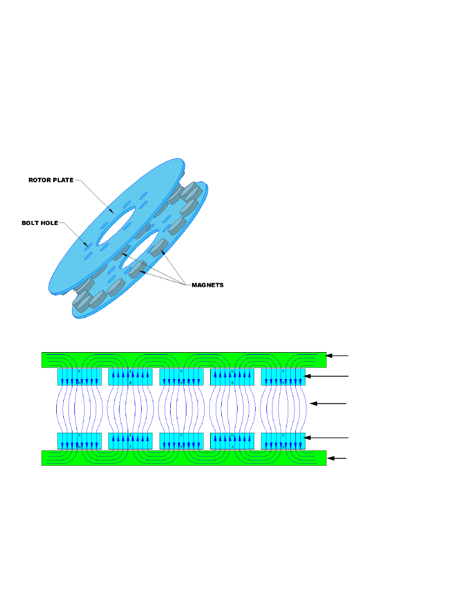
Concentrating Magnetic Energy
The magnetic field is manipulated to our advantage, when making permanent magnet
alternators. By concentrating the magnetic flux between two opposite magnet poles, and
capturing the flux in iron plates that would otherwise be wasted, we direct as much energy as
we can through the gap between the faces.
The final product usually looks like this:
This set of rotors features round magnets.
This is common on smaller axial-flux
alternators, but as they get larger, it is often
more practical to use rectangular magnets,
which are available in larger sizes, and the
wire coils are more compact. It is important
that the rotors be made of steel or iron, so
that the magnetic flux is conducted by them.
The magnets are arranged in a N-S-N-S
pattern around the circumference of the
rotors. Opposite poles face each other. If
you trace the lines of flux, they travel from
one magnet face, straight to the magnet face
opposite, then travel through the steel rotor
plate to the next magnet, and back across
the gap. Coils of wire in the gap capture the
magnetic energy in those field lines.
Rotors of a Small Permanent-Magnet Alternator
ROTOR PLATE
MAGNETS
“THE GAP”
MAGNETS
ROTOR PLATE
Flux Lines Traced Through a Dual-Rotor Permanent-Magnet Alternator
The path of magnetic flux should be more clear with the diagram above. The flux has been
concentrated by confining it between the plates. The flux also alternates between North and
South. A compass inside this gap as the rotors turn would flip back and forth frantically. A
compass outside the plates is weakly affected, because the fields have been confined.
Basic Principles Of The Homemade Axial Flux Alternator
Steven Fahey
Version 1 December 18, 2006
Page 5 of 15
Harnessing the Magnetic Energy
Now we come to the humble coil of wire. It doesn’t do much on its own, but in the presence of
magnetic fields, interesting things happen. A single loop of wire encloses a certain amount of
area. The field passing through this area is a “magnetic flux”. It is measured in Webers.
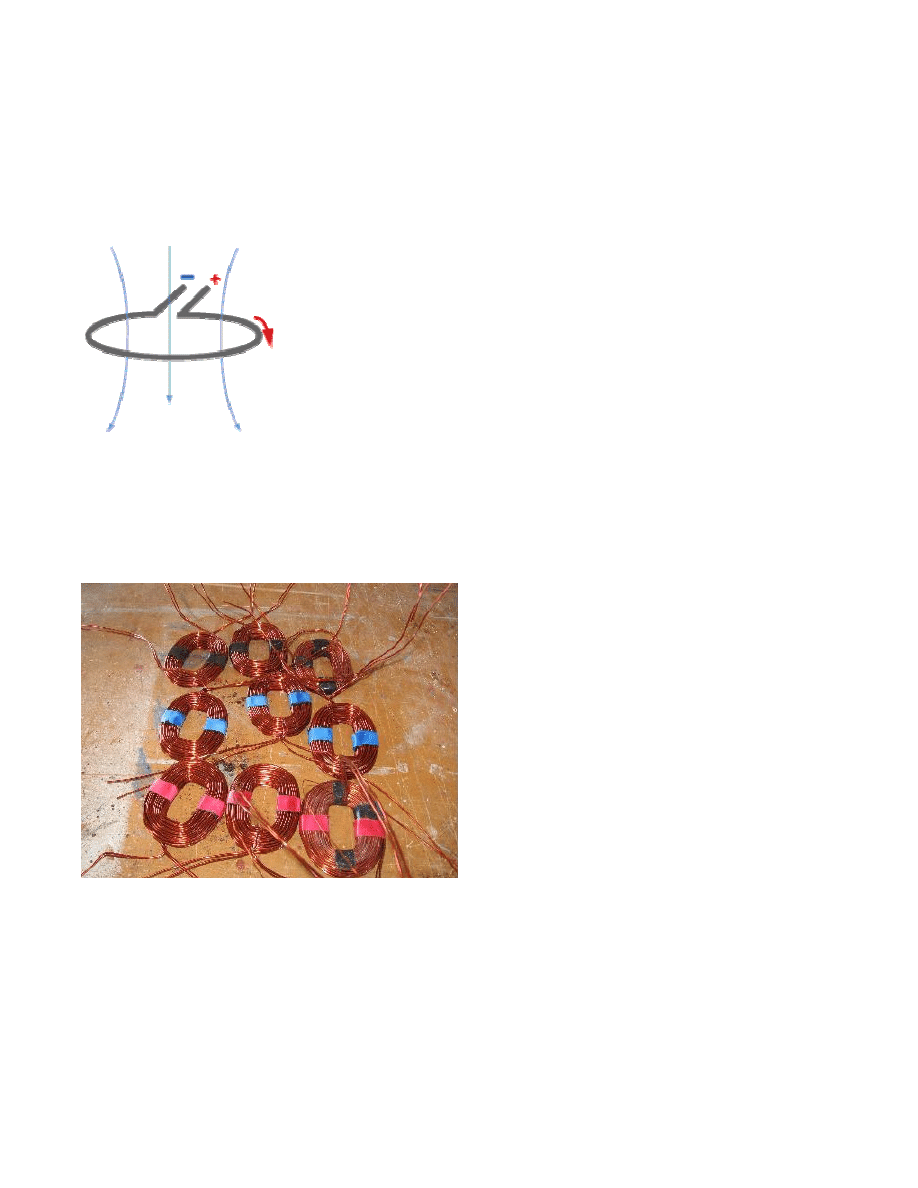
Not much happens when the surrounding magnetic field is sitting
still, but when you put the system in motion, a voltage potential is
produced. The more rapidly the magnetic field changes (either
greater or lesser), the more voltage is created.
It doesn’t actually matter how the field is changed for the
phenomenon to occur. You may have magnets that get closer
together, that oscillate back and forth, flip over and over, or
perhaps you don’t move the magnets at all, and instead flip the
coil back and forth.
In our machine, coils of wire are held steady, while the magnets spin past on the rotors.
Because the magnets were arranged N-S-N-S, the direction of the field flips each time a
magnet goes by. Each coil sees a flipped magnetic field, and pulse of electricity is produced.
When the field flips back, a pulse of opposite voltage is created. This coil is now producing
alternating voltage.
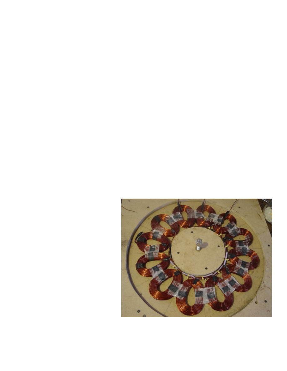
Here is a set of 9 coils that were wound
for a Permanent Magnet Alternator. They
are all the same size, and have the same
number of turns each.
Wire comes in a variety of sizes. The
diameter (or “gauge”) of the wire
determines the maximum amount of
current it can carry. Heavier wire can
carry more current than thinner wire. The
builder selects a wire size that allows the
current required for his design, but no
bigger.
If a single loop of wire captures a certain amount of voltage in a changing magnetic field, then
more of those loops will capture more voltage. The builder wants many turns of wire to
capture as much as possible. This objective conflicts with the objective of allowing more
current, because heavier wire takes more space. Less turns of heavy wire, or more turns of
thin wire. A balance is sought by the builder to meet his needs. Experienced builders know
off-hand how to strike the right balance. It is more of a mystery to the new recruit. Hopefully
the diagrams at the end of this document will help.
Basic Principles Of The Homemade Axial Flux Alternator
Steven Fahey
Version 1 December 18, 2006
Page 6 of 15
Coils of Wire in the Stator
If regular jacketed wire was used to wind coils, a lot of space would be wasted in plastic
jackets. A solution was found a long time ago, and wire can be bought that is coated in a thin
non-conductive enamel. When coils of enamelled wire are wound, each loop is isolated from
the other, and the maximum compactness occurs.
Connecting the coils of wire introduces an important question in the design of the Permanent
Magnet Alternator: Will there be 3 separate phases or just 1?
Single phase alternators are simple to hook up – all coils are wired in series with each other,
and they all work together to make one large pulse at the same time. While this is simple, the
windmill experiences quite an abrupt “bump” for each pulse. It can hinder windmill
performance and cause damaging vibration. Builders still use single phase when it’s
convenient, and adapt the design to resist the vibration. It is also more complicated to
overcome the inefficiency when rectifying that voltage to put DC into a battery, but it can be
done.
A more elegant solution is to wire up the coils for 3-phase operation. At any given point, only
one third of the alternator is at peak power, the other two are either dropping or rising to their
next peak. Vibration is reduced not only by having peak currents 1/3 as intense, but also by
having them 3 times more often. When rectifying the 3-phase power so that a DC battery can
be charged, the current is also much smoother. The cost of extra rectifiers should not be
considered an obstacle. They will last a long time if properly selected.
When the coils of wire are cast
together into one plate, they are
supported as a unit called a “stator”
(it remains “static” while the rotor
rotates). Builders usually arrange
the coils in a star-shaped pattern in
a flat mould. Into the mould they
pour a polyester or epoxy resin.
Then they close the mould, and
when it has cured, the stator comes
out as one big disk with the coils
encapsulated inside. All of the
internal electrical connections were
made in advance. Either they
selected one particular 3-phase
connection arrangement, or they
have enough wires coming out to
allow some external connection
changes. (See Appendix B for how it
can be done).
Basic Principles Of The Homemade Axial Flux Alternator
Steven Fahey
Version 1 December 18, 2006
Page 7 of 15
Magnet and Coil Matching
In an alternator producing 3-phase power, then one group of coils is at peak current while the
others are not. Therefore the magnets align with only one phase at a time. Instead of figuring
out how this is done from scratch, here’s the trick:
For every coil of wire in the 3-phase stator, there are 1.33 magnets.
No, don’t go slicing a magnet in half. The
absolute minimum number of coils in a 3-
phase alternator is 3 coils. One for each
phase. You would therefore need 4
magnets. Actually, that would be fairly
clunky. Here are some typical combinations:
Anything with more than 24 magnets is getting complicated, and the first-time builder should
beware. Similarly, varying the proportion of magnets and coils begs trouble, unless you know
how to avoid the pitfalls of making single-phase alternators (but you wouldn’t be a newbie).
Matching the Alternator and Prop
The decision on how many coils/magnets to put into the Alternator is somewhat arbitrary,
somewhat mystical. Basically, the more coils you have, the more voltage you produce (if all
other parameters stay the same). The stator will produce less current, but that may be offset
by a windmill speed range that captures more energy in the long run.
So far, we haven’t mentioned the wind mill blades that will ultimately be attached to the
alternator. When at the point of deciding how to configure the stator, the size and design of
the windmill must also be considered. Does the windmill run fast or slow? Are there often
strong winds that, if harnessed, would be of benefit? Are winds usually light, requiring a
windmill that gets the most out of a gentle breeze?
Once a size and speed range of the windmill has been chosen, the builder can proceed with
the selection of a stator configuration. Usually, the purpose of this machine is to charge
batteries. If you hook the PMA to the rectifiers, and the rectifiers to the batteries, then you
effectively clamp the voltage to a specific value, either 12V, 24, or sometimes 48V, depending
on your system. The size and gauge of wire should be selected to produce the right voltage.
The batteries are a load on the Alternator. The charging voltage will rise to a peak level (about
10% above the battery’s standard voltage), and then all your gains are in the current produced.
It takes more work for the alternator to produce more voltage. In the windmill situation, higher
winds turn the mill faster, and provide more energy to overcome the heavy load. If the blades
are too small, however, there won’t be enough energy to start the alternator in low wind. If the
blades are too big, the alternator won’t load the prop efficiently and they will spin too fast.
Coils
Magnets
# Coils Per
Phase
6
8
2
9
12
3
12
16
4
15
20
5
18
24
6
Basic Principles Of The Homemade Axial Flux Alternator
Steven Fahey
Version 1 December 18, 2006
Page 8 of 15
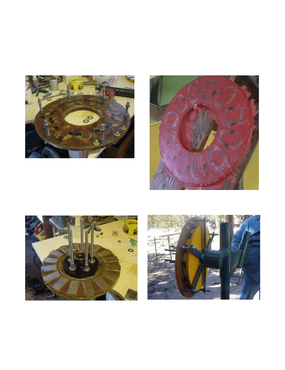
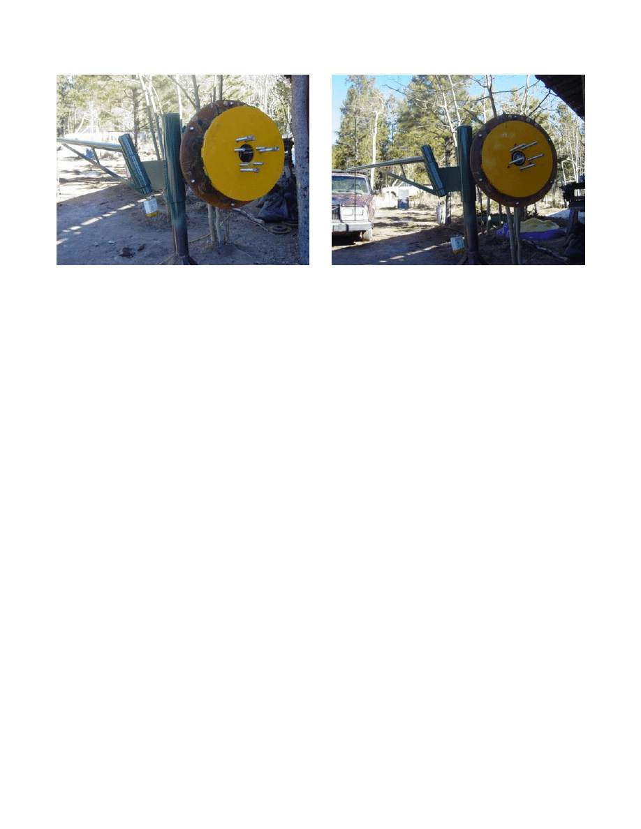
Mounting The Rotor and Stator Together
The stator is fixed while the rotor turns. How do people usually put this together? The best
way to start is to see how others have done it. There are several ways, but most resemble the
hub of an automobile; in fact, automobile hubs are usually used!
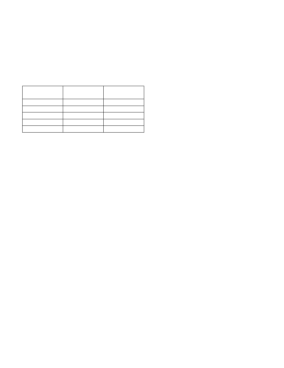
You can see 12 coils in these stators:
There are 16 magnets on the rotors below:
Below you can see the process of assembly of the rotors and stator.
One Magnet Rotor Mounted to Hub
Rotor and Hub Mounted on Tower Head
Jacking Screws Extend Up to Mount
Stator is in Position in Front of The Rotor
And Adjust The Opposite Rotor
Basic Principles Of The Homemade Axial Flux Alternator
Steven Fahey
Version 1 December 18, 2006
Page 9 of 15
Second (Opposite) Rotor Being
Second Rotor in Position
Lowered Into Position
Technical Data
What performance should the Permanent Magnet Alternator have? Dan Bartmann tests his
alternators and has collected a lot of data over the years.
The Rotors weigh 23 pounds each (13 Pounds of magnets + steel plate X 2)
The Stator weighs nearly 20 pounds (16 pounds of copper)
At 80 RPM, this alternator will produce 50 Volts, unloaded. When connected to a 48V Battery
system, Dan has recorded 600 Watts at 100 RPM. (Roughly 12 Amps). This is actually a
fairly large PMA, suitable for a windmill size of about 17 feet diameter. At higher wind speeds,
the prop turns much faster and he can capture upwards of 3 kiloWatts.
A more modest size of alternator, with a 6-8 foot prop, could also produce up to 500 Watts, but
at a significantly higher RPM. Smaller props naturally turn faster, so a good match can be
made by the beginner who works carefully to select prop and alternator operating ranges that
coincide.

Basic Principles Of The Homemade Axial Flux Alternator
Steven Fahey
Version 1 December 18, 2006
Page 10 of 15
Where to Start With Your Wind Turbine
There are a lot of questions to be asked at the beginning. One of the best ways to start is to
pick something that works, that is well documented, and to follow the instructions carefully.
Hugh Piggott, Dan Bartmann, and Ed Lenz all have well-designed wind turbine projects that
offer the beginner an excellent start. And they’re not the only ones.
1
What will I do with the power?
Often Renewable Energy systems are designed to charge a bank of batteries. An inverter
turns the battery voltage into AC that household appliances and lights can use. It doesn’t have
to be this way. You may want to put the energy to heating coils in your house’s heating
system. Maybe you want to heat water. The electricity may be useful in your house, or
instead in a remote building with no power at all. Maybe you’re ambitious and can feed it back
into the grid. (Or maybe you’re looking for the perfect lawn ornament to impress your
neighbour).
2
How much power do I need?
That jumbo windmill could light every light in your house, but how can you commit to that scale
of project on your first time out? You don’t seriously think you can run your air conditioning
system all summer on a puny wind turbine, do you? If you’re building it just for the fun of it,
then the right size is the size you can handle. If you have a purpose in mind, then figure out
what you need, apart from what you want, and how you can conserve to make the job easier.
2
Where will the wind come from?
Something we often take for granted. “Just build it – then put it in the wind…” but most of us
live near trees, buildings, neighbours, etc. The location and the wind you’ll get had better
figure into the design early. If you have light wind most of the time, then you probably want a
large windmill that’s producing power even when turning slowly – though it won’t be able to
take full advantage of strong winds. Or… you often get strong winds and want to capture all
that energy – but it may not produce anything in lighter breezes.
3
How long will this take?
This project could take a while. You’re going to draw a lot of drawings, cut a lot of wood, drill a
lot of holes in steel, weld a lot of tubing, mix lots of epoxy, wind a lot of wire, and stand around
scratching your head in puzzlement quite a lot, too. My dumb mistake: building two
simultaneously. It takes twice as long to get anything finished!
4
Do I have to do it myself?
There are a lot of companies that build these things for you. You get the whole thing, too;
tower, inverter, batteries, etc. Go the DIY route if you’re sure you’re going to enjoy the
experience and finish the job. But you don’t seriously think that DIY is a lot cheaper, do you?

Basic Principles Of The Homemade Axial Flux Alternator
Steven Fahey
Version 1 December 18, 2006
Page 11 of 15
To Learn More
Below is a brief bibliography of places to go to learn more about building windmills. You can
start here, and then venture out into the enormous volume of information
DIY Projects
Hugh Piggott
www.scoraigwind.com
Dan Bartmann
www.otherpower.com
Ed Lenz
www.windstuffnow.com
The Backshed
www.thebackshed.com/Windmill
Scientific Research
Sandia National Labs
www.sandia.gov/wind/
NREL
www.nrel.gov/wind/
UIUC Airfoil Data
www.ae.uiuc.edu/m-selig/
ECN (Dutch)
www.ecn.nl/en/
Electrical Theory
All About Circuits
www.allaboutcircuits.com/
FEMM (Magnet Models)
www.femm.foster-miller.net/index.html
Commercial Wind Turbine Manufacturers
Bergey Windpower
www.bergey.com/
Southwest WindPower
www.windenergy.com/
Jacobs
www.windturbine.net/
Windmission
www.windmission.dk/index.html
Marlec
www.marlec.co.uk/products/products.htm
Flowtrac
www.nimnet.asn.au/~kali/
African Windpower
www.scoraigwind.com/african36/
AeroMax
aeromag.com/
Wind Energy Associations and Watchdogs
AWEA (USA)
www.awea.org
CANWEA (Canada)
www.canwea.ca
Danish Wind Insustry Assoc.
www.windpower.org
AusWEA (Australia)
www.auswind.org/auswea/index.html
Wind-Works by Paul Gipe
www.wind-works.org/

Basic Principles Of The Homemade Axial Flux Alternator
Steven Fahey
Version 1 December 18, 2006
Page 12 of 15
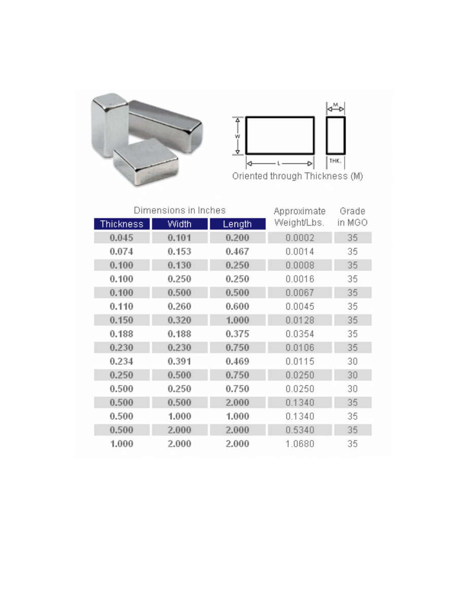
Appendix A - Wire Gauge Table
AWG
gauge
Diameter
Inches
Diameter
mm
Ohms per
1000 ft
Ohms per
km
Maximum amps for
chassis wiring
Maximum amps for
power transmission
OOOO 0.46
11.684
0.049
0.16072
380
302
OOO
0.4096
10.40384 0.0618
0.202704 328
239
OO
0.3648
9.26592
0.0779
0.255512 283
190
0
0.3249
8.25246
0.0983
0.322424 245
150
1
0.2893
7.34822
0.1239
0.406392 211
119
2
0.2576
6.54304
0.1563
0.512664 181
94
3
0.2294
5.82676
0.197
0.64616
158
75
4
0.2043
5.18922
0.2485
0.81508
135
60
5
0.1819
4.62026
0.3133
1.027624 118
47
6
0.162
4.1148
0.3951
1.295928 101
37
7
0.1443
3.66522
0.4982
1.634096 89
30
8
0.1285
3.2639
0.6282
2.060496 73
24
9
0.1144
2.90576
0.7921
2.598088 64
19
10
0.1019
2.58826
0.9989
3.276392 55
15
11
0.0907
2.30378
1.26
4.1328
47
12
12
0.0808
2.05232
1.588
5.20864
41
9.3
13
0.072
1.8288
2.003
6.56984
35
7.4
14
0.0641
1.62814
2.525
8.282
32
5.9
15
0.0571
1.45034
3.184
10.44352 28
4.7
16
0.0508
1.29032
4.016
13.17248 22
3.7
17
0.0453
1.15062
5.064
16.60992 19
2.9
18
0.0403
1.02362
6.385
20.9428
16
2.3
19
0.0359
0.91186
8.051
26.40728 14
1.8
20
0.032
0.8128
10.15
33.292
11
1.5
21
0.0285
0.7239
12.8
41.984
9
1.2
22
0.0254
0.64516
16.14
52.9392
7
0.92
23
0.0226
0.57404
20.36
66.7808
4.7
0.729
24
0.0201
0.51054
25.67
84.1976
3.5
0.577
25
0.0179
0.45466
32.37
106.1736 2.7
0.457
26
0.0159
0.40386
40.81
133.8568 2.2
0.361
27
0.0142
0.36068
51.47
168.8216 1.7
0.288

Basic Principles Of The Homemade Axial Flux Alternator
Steven Fahey
Version 1 December 18, 2006
Page 13 of 15
28
0.0126
0.32004
64.9
212.872
1.4
0.226
29
0.0113
0.28702
81.83
268.4024 1.2
0.182
30
0.01
0.254
103.2
338.496
0.86
0.142
31
0.0089
0.22606
130.1
426.728
0.7
0.113
32
0.008
0.2032
164.1
538.248
0.53
0.091
Metric
2.0
0.00787
0.200
169.39
555.61
0.51
0.088
33
0.0071
0.18034
206.9
678.632
0.43
0.072
Metric
1.8
0.00709
0.180
207.5
680.55
0.43
0.072
34
0.0063
0.16002
260.9
855.752
0.33
0.056
Metric
1.6
0.0063
0.16002
260.9
855.752
0.33
0.056
35
0.0056
0.14224
329
1079.12
0.27
0.044
Metric
1.4
.00551
.140
339
1114
0.26
0.043
36
0.005
0.127
414.8
1360
0.21
0.035
Metric
1.25
.00492
0.125
428.2
1404
0.20
0.034
37
0.0045
0.1143
523.1
1715
0.17
0.0289
Metric
1.12
.00441
0.112
533.8
1750
0.163
0.0277
38
0.004
0.1016
659.6
2163
0.13
0.0228
Metric 1 .00394
0.1000
670.2
2198
0.126
0.0225
39
0.0035
0.0889
831.8
2728
0.11
0.0175
40
0.0031
0.07874
1049
3440
0.09
0.0137
Basic Principles Of The Homemade Axial Flux Alternator
Steven Fahey
Version 1 December 18, 2006
Page 14 of 15
Appendix B - Neo Magnet Data
Basic Principles Of The Homemade Axial Flux Alternator
Steven Fahey
Version 1 December 18, 2006
Page 15 of 15
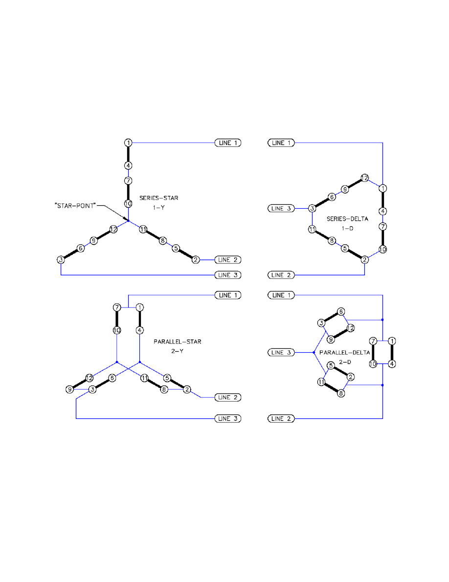
Appendix C - 3-Phase Connections
The simplest way to connect the coils of a 3-phase alternator is in “Star”. Join the ending wires
together, and the three start wires come out. Each phase comes out of the start wires.
Alternatively, a “Delta” connection can be made by joining the starts and ends of each
successive phase together.
Wyszukiwarka
Podobne podstrony:
My Homemade wind generator
Plans For Wind Generator Pt250 Blade Plan10A
[2003] Constant Voltage Permanent Magnet Wind Generator
Wind Generator Project Wood X
Home Made Recipes For Natural Beauty
Budujemy turbinę wiatrową w oparciu o projekt Hugh Piggotta z książki Wind power Workshop
An Igbt Inverter For Interfacing Small Scale Wind Generators To Single Phase Distributed Power Gener
eReport Wine Taste of Home Made Wines
Home made Toys for Girls and Bo A Neely Hall
Transient stability simulation of power system including Wind generator by PSCAD EMTDC
Home Made Cat Food Recipes Liz Wallace Mills
HOW TO BUILD A CHISPITO WIND GENERATOR
Hugh Piggott Blade Design
[2006] Analysis of a Novel Transverse Flux Generator in direct driven wind turbine
więcej podobnych podstron